


Isuzu
4HK-1 and 6HK-1
ENGINE
FUEL SYSTEM
CE APPLICATIONS
Revised 8/29/06 |
Form Number 5137 |
1
Table Of Contents
2
Isuzu 4HK-1 and 6HK-1 Engine Overview
The Tier III CX330 Excavators are equipped with an Isuzu 6HK-1 model common rail fuel system Engine. The Isuzu 4HK-1 model will be used in at least one other
Excavator model. These engines have 4 valves per cylinder, operated by a single overhead cam to optimize air flow, fuel economy and emissions. The injector is now located at the center of the piston under the valve cover. The fuel system is now totally electronically controlled. These engines use an water cooled Exhaust Gas Recirculation, (EGR) system, which allows a controlled amount of exhaust gas to return back to the intake. This EGR system is used to reduce the emissions level of the engine. These engines also use an air to air aftercooling intake air system. The air to air intake system ports pressurized air flow between the turbocharger and the intake manifold through an air to air heat exchanger in front of the radiator. The 4HK-1 model has a displacement of 317 cubic inches (in3) or 5193 cubic centimeters (cc). The 6HK-1 model has a displacement of 475 cubic inches (in3) or 7790cubic centimeters (cc).
The ECM calculates the basic injection amount based on the signals from throttle position sensor, boost pressure sensor, crank position sensor, cam position sensor, etc.
It regulates the opening/closing period of common rail pressure control valve and the electric activation of each injector according to the common rail pressure, engine coolant temperature, etc. at this time, to correct the optimum injection timing and injection amount.
At engine start (after the key switch is turned to the START position to start the engine, and until the return of the key switch to the ON position), the fuel injection quantity is controlled based on information from the start signal, engine speed, and engine coolant temperature. At low temperature, the fuel injection quantity increases. When the engine starts completely, this boosted quantity mode at starting is cancelled and normal running mode is restored.
The ECM calculates the current altitude based on the barometric pressure sensor signal. It corrects the fuel flow according to the altitude etc. at this time.
The Excavator machine controller communicates with the engine controller (ECM) via the CAN Data Bus system to control engine speed, return to idle command, activate the work modes and also to set the engine speed required for the breaker mode.
Engine Performance Needs
1.Air
2.Compression
3.Fuel
3

Isuzu 4HK-1 and 6HK-1 Engine Overview
The electronic control system for the Isuzu 4HK-1 and 6HK-1 Engines use input information from a number of sensors and from the Excavator controller to determine the quantity and timing of the fuel delivery to the engine.
The engine control module (ECM), is located on the inside rear of the cab. The ECM has two connectors, one an 81 pin and one 40 pin, for inputs and outputs. The engine control module requires downloading of control software to give it the ability to control all functions.
Inputs to 40 pin engine harness connector:
•The common rail fuel pressure sensor has 3 wires and is located on the common rail. This sensor detects the fuel pressure in the common rail, converts the pressure into a voltage signal, and sends the signal to the ECM. Higher common rail pressure provides higher fuel pressure sensor voltage while lower pressure provides lower fuel pressure sensor voltage.
•The 2 wire variable resistor fuel temperature sensor is installed on the fuel supply pump. The fuel temperature sensor measures the temperature of the drain fuel from the pump. When the fuel temperature sensor is cold, the sensor resistance is high.
When the fuel temperature increases, the sensor resistance decreases. With high sensor resistance, the ECM detects a high voltage on the signal circuit. With lower sensor resistance, the ECM detects a lower voltage on the signal circuit.
Fuel Temp. |
Fuel Temp. |
|
Ohms |
Fuel Temp. |
Fuel |
Ohms Ω |
(°C) |
(°F) |
|
Ω |
(°C) |
Temp. (°F) |
|
140 |
284 |
75 |
40 |
104 |
1,150 |
|
120 |
248 |
111 |
20 |
68 |
2,450 |
|
100 |
212 |
184 |
0 |
32 |
5,740 |
|
80 |
176 |
318 |
-20 |
-4 |
15,000 |
|
60 |
140 |
584 |
-40 |
-40 |
45,770 |
|
•The 2 wire engine coolant temperature sensor is located on the thermostat housing at the right front corner of the engine. The coolant sensor's temperature detection component uses a thermistor. A 5 volt reference voltage is applied at all times to the sensor from the ECM. The ECM detects a voltage change due to a resistance value change in the sensor caused by the coolant temperature change.
Coolant |
Coolant |
Ohms |
Coolant |
Coolant |
Ohms Ω |
Temp. (°C) |
Temp. (°F) |
Ω |
Temp. (°C) |
Temp. (°F) |
|
140 |
284 |
76 |
40 |
104 |
1,161 |
120 |
248 |
118 |
20 |
68 |
2,500 |
100 |
212 |
190 |
0 |
32 |
5,773 |
80 |
176 |
325 |
-20 |
-4 |
15,216 |
60 |
140 |
591 |
-40 |
-40 |
47,365 |
4

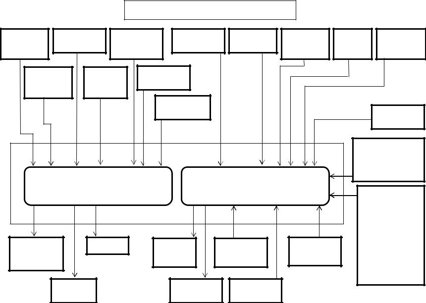
Isuzu 6HK1 Common Rail Engine Fuel System
Common |
Fuel Temp |
Coolant |
Intake Air |
Boost Temp |
Barometric |
ENG Oil |
Engine Stop |
|||
Rail Fuel PSI |
|
Sensor |
Temperature |
Temp. Sensor |
Sensor |
AMB PSI |
|
PSI |
Switch |
|
Sensor |
|
|
|
Sensor |
|
|
Sensor |
|
Sensor |
|
Crankshaft |
Camshaft |
Boost PSI |
|
|
|
|
|
|||
Position |
|
Position |
Sensor |
|
|
|
|
|
||
Sensor |
|
|
Sensor |
|
EGR Position |
|
|
|
|
|
|
|
|
|
|
|
|
|
|
|
|
|
|
|
|
|
Sensor |
|
|
|
|
Start Signal |
|
|
|
|
|
|
|
|
|
|
(Fuel Boost) |
|
|
|
|
|
|
|
|
|
Power Supply |
|
|
|
|
|
|
|
|
|
|
1 Ignition Wire |
|
|
|
|
|
|
|
|
|
|
2 Positive Wires |
|
|
Engine Harness 40 Pin |
Engine Harness 81 Pin |
|
6 Ground Wires |
||||||
|
|
|
|
|||||||
|
|
Connector A1 |
|
|
|
|||||
|
|
|
Connector A0 |
|
|
CAN Data Bus |
||||
Engine Control Module |
|
|
|
|||||||
|
|
|
|
|
Connector |
|||||
|
|
|
|
|
|
|
|
|
|
Throttle, |
|
|
|
|
|
|
|
|
|
Idle Up/Down, |
|
Pump PSI |
|
|
Injectors |
Main ECM |
Diagnostic |
Memory Clear |
|
Work Modes, |
||
|
|
Breaker Mode, |
||||||||
Control Valve |
|
|
|
|
Power |
Switch X24 |
Switch X23 |
|
||
|
|
|
|
|
|
Tach, |
||||
(SCV) |
|
|
|
|
Relay |
|
|
|
|
|
|
|
|
|
|
|
|
(Instrumentation |
|||
|
|
|
|
|
|
|
|
|
||
EGR DC |
|
|
Glow |
Data Link |
|
|
|
& Faults) |
||
|
|
|
|
|
|
|||||
|
Motor |
|
|
Relay |
Diag Conn X4 |
|
|
|
|
|
|
|
|
|
|
5 |
|
|
|
|
|
Isuzu 4HK-1 and 6HK-1 Engine Overview (continued)
Inputs to 40 pin engine harness connector(continued):
•The 2 wire crankshaft position sensor (CKP) is located on the flywheel housing at the left rear corner of the engine. The CKP sensor detects 45 projections equally spaced every 7.5° around the flywheel periphery. There is also a space (equal to 3 projections) to act as a top dead center (TDC) reference signal for the engine control module (ECM). With these 45 pulses and the TDC reference signal, the ECM calculates the engine speed and exact position of the crankshaft.
•The 2 wire camshaft position sensor (CMP) is located on the cylinder head at the rear of the camshaft gear. The camshaft position sensor detects a total of the number of the cylinders in the engine plus an extra one. The extra hole indicates the top dead center position of number 1 cylinder. Five through holes (four holes arranged equally every 90° on the gear and one reference hole) on the camshaft gear flange surface on the 4HK-1 Engine. Seven through holes (six holes arranged equally every 60° on the gear and one reference hole) on the camshaft gear flange surface on the 6HK-1 Engine. The camshaft position sensor indicates the rotational position of the camshaft to the ECM. The CMP signal input, determines the crank angle and the ECM can use it to control fuel injection and calculate the engine speed. The crankshaft position sensor (CKP) typically controls these functions, however it is done by CMP sensor if the CKP sensor is faulty.
Diagnostic aid
If there is relevant Error Code to the crankshaft (CKP) sensor and Camshaft (CMP) sensor, the engine will not start until memory clear is performed.
If an intermittent trouble is suspected, the following may be the cause:
•Improper connection of harness connector
•Defective harness routing
•Worn harness cover
•Wire disconnection inside harness cover
•The 3 wire boost pressure sensor is located in the piping to the intake manifold of the engine. The sensor converts the boost pressure into the voltage signal and sends it to engine control module (ECM). The ECM should detect a higher signal voltage at a high boost pressure.
•The 4 wire Exhaust Gas Recirculation (EGR) position sensor is installed in EGR valve and detects the valve lift amount of EGR.
Note:
Do not disassemble the EGR position sensor. If it is faulty, replace it as EGR valve assembly.
6

Isuzu 6HK1 Common Rail Engine Fuel System
Common |
Fuel Temp |
Coolant |
Intake Air |
Boost Temp |
Barometric |
ENG Oil |
Engine Stop |
|||
Rail Fuel PSI |
|
Sensor |
Temperature |
Temp. Sensor |
Sensor |
AMB PSI |
|
PSI |
Switch |
|
Sensor |
|
|
|
Sensor |
|
|
Sensor |
|
Sensor |
|
Crankshaft |
Camshaft |
Boost PSI |
|
|
|
|
|
|||
Position |
|
Position |
Sensor |
|
|
|
|
|
||
Sensor |
|
|
Sensor |
|
EGR Position |
|
|
|
|
|
|
|
|
|
|
|
|
|
|
|
|
|
|
|
|
|
Sensor |
|
|
|
|
Start Signal |
|
|
|
|
|
|
|
|
|
|
(Fuel Boost) |
|
|
|
|
|
|
|
|
|
Power Supply |
|
|
|
|
|
|
|
|
|
|
1 Ignition Wire |
|
|
|
|
|
|
|
|
|
|
2 Positive Wires |
|
|
Engine Harness 40 Pin |
Engine Harness 81 Pin |
|
6 Ground Wires |
||||||
|
|
|
|
|||||||
|
|
Connector A1 |
|
|
|
|||||
|
|
|
Connector A0 |
|
|
CAN Data Bus |
||||
Engine Control Module |
|
|
|
|||||||
|
|
|
|
|
Connector |
|||||
|
|
|
|
|
|
|
|
|
|
Throttle, |
|
|
|
|
|
|
|
|
|
Idle Up/Down, |
|
Pump PSI |
|
|
Injectors |
Main ECM |
Diagnostic |
Memory Clear |
|
Work Modes, |
||
|
|
Breaker Mode, |
||||||||
Control Valve |
|
|
|
|
Power |
Switch X24 |
Switch X23 |
|
||
|
|
|
|
|
|
Tach, |
||||
(SCV) |
|
|
|
|
Relay |
|
|
|
|
|
|
|
|
|
|
|
|
(Instrumentation |
|||
|
|
|
|
|
|
|
|
|
||
EGR DC |
|
|
Glow |
Data Link |
|
|
|
& Faults) |
||
|
|
|
|
|
|
|||||
|
Motor |
|
|
Relay |
Diag Conn X4 |
|
|
|
|
|
|
|
|
|
|
7 |
|
|
|
|
|
Isuzu 4HK-1 and 6HK-1 Engine Overview (continued)
Inputs to 81 pin engine harness connector:
•The 2 wire intake air temperature (IAT) sensor is installed on intake air tube and detects the temperature of intake air for optimum fuel injection control.
•The 2 wire boost temperature sensor is installed onto the EGR valve on the upstream side of intake manifold. The sensor is a thermistor type. The resistance in the sensor changes as the temperature changes. When the intake temperature sensor is cold, the sensor resistance is high. When the intake temperature increases, the sensor resistance decreases. With high sensor resistance, the ECM detects a high voltage on the signal circuit. With lower sensor resistance, the ECM detects a lower voltage on the signal circuit.
•The 3 wire barometric pressure sensor is installed on the machine and converts the ambient barometric pressure into a voltage signal. The ECM calculates barometric pressure by this voltage signal and corrects the fuel injection amount (high-altitude correction) as the machine works at a higher elevation.
•The 3 wire engine oil pressure sensor is located on the left side of the engine just below and forward of the high pressure injection pump.
•An engine emergency stop signal is sent from the machine controller to the engine controller. The machine controller receives an engine stop signal from the stop switch located in the instrument cluster.
•As the engine is started (after the key switch is turned to the START position to start the engine, and until the return of the key switch to the ON position), optimum fuel injection quantity is delivered based on information from the starter switch signal, engine speed, and the engine coolant temperature sensor (ECT). At low temperature, the fuel injection quantity increases. As the engine starts completely, this boosted quantity mode at starting is cancelled and normal running mode is restored.
•Power Supply – Ignition power is sent to the engine control module (ECM) any time that the key switch is in the run position. When the ignition signal is present, the ECM activates the main relay. Once the Main Relay (K33 on machine schematic) is activated, battery power is fed to the ECM through the relay normally open (NO) contact to pins number 2 and 6. When the key switch is turned to the off position, the ECM continues to hold the main relay activated for a period of time to allow the ECM to power down safely. This delay is about 10 seconds. The ECM has six ground connections in total.
8
Isuzu 6HK1 Common Rail Engine Fuel System
Common |
Fuel Temp |
Coolant |
Intake Air |
Boost Temp |
Barometric |
ENG Oil |
Engine Stop |
|||
Rail Fuel PSI |
|
Sensor |
Temperature |
Temp. Sensor |
Sensor |
AMB PSI |
|
PSI |
Switch |
|
Sensor |
|
|
|
Sensor |
|
|
Sensor |
|
Sensor |
|
Crankshaft |
Camshaft |
Boost PSI |
|
|
|
|
|
|||
Position |
|
Position |
Sensor |
|
|
|
|
|
||
Sensor |
|
|
Sensor |
|
EGR Position |
|
|
|
|
|
|
|
|
|
|
|
|
|
|
|
|
|
|
|
|
|
Sensor |
|
|
|
|
Start Signal |
|
|
|
|
|
|
|
|
|
|
(Fuel Boost) |
|
|
|
|
|
|
|
|
|
Power Supply |
|
|
|
|
|
|
|
|
|
|
1 Ignition Wire |
|
|
|
|
|
|
|
|
|
|
2 Positive Wires |
|
|
Engine Harness 40 Pin |
Engine Harness 81 Pin |
|
6 Ground Wires |
||||||
|
|
|
|
|||||||
|
|
Connector A1 |
|
|
|
|||||
|
|
|
Connector A0 |
|
|
CAN Data Bus |
||||
Engine Control Module |
|
|
|
|||||||
|
|
|
|
|
Connector |
|||||
|
|
|
|
|
|
|
|
|
|
Throttle, |
|
|
|
|
|
|
|
|
|
Idle Up/Down, |
|
Pump PSI |
|
|
Injectors |
Main ECM |
Diagnostic |
Memory Clear |
|
Work Modes, |
||
|
|
Breaker Mode, |
||||||||
Control Valve |
|
|
|
|
Power |
Switch X24 |
Switch X23 |
|
||
|
|
|
|
|
|
Tach, |
||||
(SCV) |
|
|
|
|
Relay |
|
|
|
|
|
|
|
|
|
|
|
|
(Instrumentation |
|||
|
|
|
|
|
|
|
|
|
||
EGR DC |
|
|
Glow |
Data Link |
|
|
|
& Faults) |
||
|
|
|
|
|
|
|||||
|
Motor |
|
|
Relay |
Diag Conn X4 |
|
|
|
|
|
|
|
|
|
|
9 |
|
|
|
|
|
Isuzu 4HK-1 and 6HK-1 Engine Overview (continued)
Inputs to 81 pin engine harness connector: (continued)
•The CAN (Controller Area Network) Data Bus Connector transmits communication between the engine controller and the Excavator controller. This connector transmits throttle, idle up/down, work mode, breaker mode, tachometer, instrumentation and fault code information.
•The memory clear (X23), diagnostic switch (X24) and data link (X4) connectors are not used with the Case Electronic Service Tool (EST) diagnostic system. They are required when using the Tech 2 Diagnostic Tool.
Outputs from 81 pin engine harness connector:
•When the ignition signal is present from the keyswitch, the ECM activates the main relay. Once the Main Relay (K33 on machine schematic) is activated, battery power is fed to the ECM through the relay normally open (NO) contacts to pins number 2 and 6. When the key switch is turned to the off position, the ECM continues to hold the main relay activated for a period of time to allow the ECM to power down safely. This delay is about 10 seconds.
•The glow control relay system consists of the ECM, glow relay, glow plug. When the key switch is turned ON with low engine coolant temperatures, the ECM determines the glow time and operates the glow relay (K2). After a certain time has elapsed, the ECM will turn the glow relay to “OFF”. Also, after-glow function allows to stabilize idling immediately after starting.
Outputs from 40 pin engine harness connector:
•The engine driven high pressure injection pump pressurizes fuel to feed to the common rail. The injection pump has a suction control valve (SCV), and a fuel temperature (FT) sensor. The suction control valve (SCV) is installed onto high pressure pump section and controls supply of fuel (discharge amount) to common rail. The engine control module (ECM) regulates period of electrical activation time of the SCV to regulate the fuel discharge amount.
Do not replace the SCV. If it is faulty, replace it as supply pump ASM.
•The exhaust gas recirculation (EGR) system recirculates a part of the exhaust gas to the engine intake to reduce the combustion temperature inside the cylinders to reduce NOx (nitrogen oxides) in the exhaust gas. The EGR valve opening is calculated according to the engine coolant temperature (ECT), the engine speed, and the target fuel injection quantity. The EGR motor is the brushless DC motor, and is driven by three phases. The ECM drives the EGR motor through the EGR motor drive circuits U, V, and W. The motor rotates with a combination of the threephase signals. The ECM sets the Error Code when the EGR motor drive duty is high and the difference between the target EGR position and actual EGR position is large.
10
Isuzu 6HK1 Common Rail Engine Fuel System
Common |
Fuel Temp |
Coolant |
Intake Air |
Boost Temp |
Barometric |
ENG Oil |
Engine Stop |
|||
Rail Fuel PSI |
|
Sensor |
Temperature |
Temp. Sensor |
Sensor |
AMB PSI |
|
PSI |
Switch |
|
Sensor |
|
|
|
Sensor |
|
|
Sensor |
|
Sensor |
|
Crankshaft |
Camshaft |
Boost PSI |
|
|
|
|
|
|||
Position |
|
Position |
Sensor |
|
|
|
|
|
||
Sensor |
|
|
Sensor |
|
EGR Position |
|
|
|
|
|
|
|
|
|
|
|
|
|
|
|
|
|
|
|
|
|
Sensor |
|
|
|
|
Start Signal |
|
|
|
|
|
|
|
|
|
|
(Fuel Boost) |
|
|
|
|
|
|
|
|
|
Power Supply |
|
|
|
|
|
|
|
|
|
|
1 Ignition Wire |
|
|
|
|
|
|
|
|
|
|
2 Positive Wires |
|
|
Engine Harness 40 Pin |
Engine Harness 81 Pin |
|
6 Ground Wires |
||||||
|
|
|
|
|||||||
|
|
Connector A1 |
|
|
|
|||||
|
|
|
Connector A0 |
|
|
CAN Data Bus |
||||
Engine Control Module |
|
|
|
|||||||
|
|
|
|
|
Connector |
|||||
|
|
|
|
|
|
|
|
|
|
Throttle, |
|
|
|
|
|
|
|
|
|
Idle Up/Down, |
|
Pump PSI |
|
|
Injectors |
Main ECM |
Diagnostic |
Memory Clear |
|
Work Modes, |
||
|
|
Breaker Mode, |
||||||||
Control Valve |
|
|
|
|
Power |
Switch X24 |
Switch X23 |
|
||
|
|
|
|
|
|
Tach, |
||||
(SCV) |
|
|
|
|
Relay |
|
|
|
|
|
|
|
|
|
|
|
|
(Instrumentation |
|||
|
|
|
|
|
|
|
|
|
||
EGR DC |
|
|
Glow |
Data Link |
|
|
|
& Faults) |
||
|
|
|
|
|
|
|||||
|
Motor |
|
|
Relay |
Diag Conn X4 |
|
|
|
|
|
|
|
|
|
|
11 |
|
|
|
|
|
Isuzu 4HK-1 and 6HK-1 Engine Overview (continued)
Outputs from 40 pin engine harness connector: (continued)
•The injectors are controlled by the engine control module (ECM). The ECM sends a common power supply to injectors 1, 3 and 5. The ECM also sends a common power supply to injectors 2, 4 and 6. The ECM fires the injectors by controlling the ground of the individual injectors. The ECM calculates the basic injection amount and timing based on the signals from throttle position sensor, boost pressure sensor, crankshaft (CKP) sensor, camshaft (CMP) sensor, etc. The timing of the injection is controlled by when the injector activates. The fuel quantity delivered is based upon the amount of time that the injector is open and also the pressure supplied by the common rail. To improve combustion in cylinders, the system injects a little fuel (preinjection or pilot injection) and ignites it at the beginning of the cycle. A second injection (main injection) delivers the fuel required deliver the horsepower needed.
12

Isuzu 6HK1 Common Rail Engine Fuel System
Common |
Fuel Temp |
Coolant |
Intake Air |
Boost Temp |
Barometric |
ENG Oil |
Engine Stop |
|||
Rail Fuel PSI |
|
Sensor |
Temperature |
Temp. Sensor |
Sensor |
AMB PSI |
|
PSI |
Switch |
|
Sensor |
|
|
|
Sensor |
|
|
Sensor |
|
Sensor |
|
Crankshaft |
Camshaft |
Boost PSI |
|
|
|
|
|
|||
Position |
|
Position |
Sensor |
|
|
|
|
|
||
Sensor |
|
|
Sensor |
|
EGR Position |
|
|
|
|
|
|
|
|
|
|
|
|
|
|
|
|
|
|
|
|
|
Sensor |
|
|
|
|
Start Signal |
|
|
|
|
|
|
|
|
|
|
(Fuel Boost) |
|
|
|
|
|
|
|
|
|
Power Supply |
|
|
|
|
|
|
|
|
|
|
1 Ignition Wire |
|
|
|
|
|
|
|
|
|
|
2 Positive Wires |
|
|
Engine Harness 40 Pin |
Engine Harness 81 Pin |
|
6 Ground Wires |
||||||
|
|
|
|
|||||||
|
|
Connector A1 |
|
|
|
|||||
|
|
|
Connector A0 |
|
|
CAN Data Bus |
||||
Engine Control Module |
|
|
|
|||||||
|
|
|
|
|
Connector |
|||||
|
|
|
|
|
|
|
|
|
|
Throttle, |
|
|
|
|
|
|
|
|
|
Idle Up/Down, |
|
Pump PSI |
|
|
Injectors |
Main ECM |
Diagnostic |
Memory Clear |
|
Work Modes, |
||
|
|
Breaker Mode, |
||||||||
Control Valve |
|
|
|
|
Power |
Switch X24 |
Switch X23 |
|
||
|
|
|
|
|
|
Tach, |
||||
(SCV) |
|
|
|
|
Relay |
|
|
|
|
|
|
|
|
|
|
|
|
(Instrumentation |
|||
|
|
|
|
|
|
|
|
|
||
EGR DC |
|
|
Glow |
Data Link |
|
|
|
& Faults) |
||
|
|
|
|
|
|
|||||
|
Motor |
|
|
Relay |
Diag Conn X4 |
|
|
|
|
|
|
|
|
|
|
13 |
|
|
|
|
|
Isuzu 4HK-1 and 6HK-1 Engine Fuel Schematic Overview
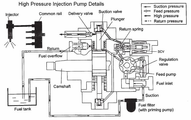
Fuel System Hydraulic Function
Fuel comes from the tank and typically will go through a prefilter assembly. From the prefilter, the fuel then flows to an electric fuel pump, located in the hydraulic pump compartment. The 24 volt electric fuel pump is powered directly by the battery relay, through the 65 amp fuse (F23) and the 10 amp electrical fuel pump fuse (F8) in the fuse box. The electric fuel pump then sends the fuel through the fuel filter also located hydraulic pump compartment to the inlet port of the high pressure injection pump.
The high pressure injection pump is mounted at the left rear of the engine. This pump needs to be timed to the engine. To install the pump, bring the engine to TDC and then align the mark on the pump drive gear to the mark on the front face of the high pressure pump. Once these conditions are met, install the injection pump. The high pressure injection pump has a shaft driven gerotor feed (charge) pump which provides fuel to the pump pressure control valve (Suction Control Valve SCV). The gerotor pump outlet pressure is controlled by the regulation valve to provide a constant pressure at the inlet of the high pressure pumping pistons. The high pressurepump PSI regulator (SCV), located in the injection pump, controls the flow output of the high pressure pump. The high pressure pump supplies the quantity of fuel to the common rail required to maintain the pressure dictated by the engine control unit (ECM). This assures that only the required amount of fuel is pressurized, improving energy efficiency and limiting heating of fuel in the system. The common rail pressure will range from 3625 to 29,000 PSI (25 to 200 MPa). Excess flow from the feed pump and internal leakage from the injection pump returns to the tank. The fuel temperature sensor (FT) monitors the temperature of this fuel.
14

15
 Loading...