


 Loading...
2008-2011MY 


WORKSHOP MANUAL
GENERAL INFORMATION

This Workshop Manual deals only with the screen toned section(s) in the table below.
|
Section |
|
Sub Section |
0 |
GENERAL INFORMATION |
0A |
General Information |
1 |
ENGINE |
1A |
Engine Control System |
|
|
1B |
Engine Mechanical |
|
|
1C |
Engine Cooling |
|
|
1D |
Engine Fuel |
|
|
1E |
Engine Electrical |
|
|
1F |
Emission Control |
|
|
1G |
Engine Exhaust |
|
|
1H |
Engine Lubrication |
|
|
1I |
Engine Speed Control System |
|
|
1J |
Induction |
|
|
1K |
Pre-Heating System |
|
|
1L |
Power Take-Off (PTO) |
2 |
SUSPENSION |
2A1 |
Air Suspension Control System |
|
|
2B |
Front Suspension |
|
|
2C |
Rear Suspension |
|
|
2D |
Wheel and Tire System |
3 |
DRIVELINE/AXLE |
3A1 |
Front Differential |
|
|
3A2 |
Rear Differential |
|
|
3C1 |
Propeller Shaft |
|
|
3C2 |
Front Axle |
|
|
3C3 |
Rear Axle |
|
|
3D |
Transfer Case |
4 |
BRAKES |
4A2 |
Brake Control System (Air Over) |
|
|
4A3 |
Brake Control System (Full Air) |
|
|
4B2 |
Brake (Air Over) |
|
|
4B3 |
Brake (Full Air) |
|
|
4C |
Anti-Lock Brake (ABS) |
|
|
4C1 |
Anti-Lock Brake (ABS)/Anti-Slip Regulator (ASR) |
|
|
4D |
Parking Brake |
|
|
4E |
Hill Start Aid (HSA) |
|
|
4F |
Speed Retarder System |
|
|
4G |
Trailer Brake |
5 |
TRANSMISSION/TRANSAXLE |
5A |
Transmission Control System |
|
|
5B |
Automatic Transmission |
|
|
5C |
Manual Transmission |
|
|
5E |
Clutch |
|
|
5G |
Power Take-Off (PTO) |
|
|
5G1 |
Side Power Take-Off |
6 |
STEERING |
6B |
Power Steering |
7 |
HVAC |
7A |
Heating and Ventilation |
|
|
7B |
Manual Air Conditioning |
|
|
7C |
Automatic Air Conditioning |
8 |
RESTRAINTS |
8A |
Seat Belt |
|
|
8B |
Supplemental Restraint System (SRS) |
|
|
8C |
SRS Control System |
9 |
BODY, CAB AND ACCESSORIES |
9A |
Lighting System |
|
|
9B |
Wiper/Washer System |
|
|
9C |
Entertainment |
|
|
9D |
Wiring System |
|
|
9E |
Instrumentation/Driver Info. |
|
|
9F |
Body Structure |
|
|
9G |
Cab |
|
|
9H |
Seats |
|
|
9I |
Security and Lock |
|
|
9K |
Exterior/Interior Trim |
|
|
9L |
Cab Mounting |
10 |
CONTROL SYSTEMS |
10B |
Vehicle Control |
11 |
FRAME AND FRAME ACCESSORIES |
11A |
Frame |


General Information 0A-1
GENERAL INFORMATION
General Information
TABLE OF CONTENTS
General Information . . . . . . . . . . . . . . . . . . . . . . . 0A-2 General Repair Instructions . . . . . . . . . . . . . . . 0A-2 Identification . . . . . . . . . . . . . . . . . . . . . . . . . . . . . 0A-3
Chassis Number/Engine Number Stamping
Position . . . . . . . . . . . . . . . . . . . . . . . . . . . . . . . 0A-3 Option Code List . . . . . . . . . . . . . . . . . . . . . . . . 0A-4 Vehicle Identification Number (VIN) . . . . . . . . 0A-11 General Precaution . . . . . . . . . . . . . . . . . . . . . . 0A-15 General Precautions . . . . . . . . . . . . . . . . . . . . 0A-15 Lifting Instruction . . . . . . . . . . . . . . . . . . . . . . . . 0A-17 Lifting Instruction . . . . . . . . . . . . . . . . . . . . . . . 0A-17 Caution for The Maintenance of Electrical Parts 0A-20 Battery Cable . . . . . . . . . . . . . . . . . . . . . . . . . 0A-20 Connector Handling Requirements . . . . . . . . . 0A-20 Handling Electronic Parts . . . . . . . . . . . . . . . . 0A-23 Cable Harness . . . . . . . . . . . . . . . . . . . . . . . . 0A-23 Regarding The Scan Tool. . . . . . . . . . . . . . . . . . 0A-25 Trouble Diagnosis Using The Scan Tool . . . . . 0A-25 Recommended Liquid Gasket . . . . . . . . . . . . . . 0A-31 Recommended Liquid Gasket. . . . . . . . . . . . . 0A-31 Recommended Thread Locking Agent. . . . . . . . 0A-33 Recommended Thread Locking Agent . . . . . . 0A-33 Maintenance Schedule. . . . . . . . . . . . . . . . . . . . 0A-34 Introduction . . . . . . . . . . . . . . . . . . . . . . . . . . . 0A-34
Maintenance Schedule
(for Euro4 specification except Europe) . . . . . 0A-35 Maintenance Schedule
(for Euro2, Euro3 specification). . . . . . . . . . . . 0A-41 Maintenance Schedule (for Europe) . . . . . . . . 0A-45 Maintenance Schedule
(CNG engine for Australia) . . . . . . . . . . . . . . . 0A-50 Maintenance Schedule
(CNG engine for Thailand) . . . . . . . . . . . . . . . 0A-54 Transmission Oil - ZF6S1000/ZF9S1110 Type 0A-58 Transmission Oil - FS8209A/FSO5206B Type 0A-65 RS23/RS40 Type Axle . . . . . . . . . . . . . . . . . . 0A-67 RS25 Type Axle . . . . . . . . . . . . . . . . . . . . . . . 0A-68
Maintenance Schedule for Severe-condition . . . 0A-69 Introduction . . . . . . . . . . . . . . . . . . . . . . . . . . . 0A-69 Maintenance Schedule for Severe-condition . 0A-69
Recommended Fluids, Lubricants and
Diesel Fuels (except Europe). . . . . . . . . . . . . . . 0A-73 Introduction . . . . . . . . . . . . . . . . . . . . . . . . . . . 0A-73 Diesel Engine Crankcase with DPD
(Low Ash Oil). . . . . . . . . . . . . . . . . . . . . . . . . . 0A-73 Diesel Engine Crankcase without DPD. . . . . . 0A-74 CNG Engine Crankcase (for Australia) . . . . . . 0A-74 CNG Engine Crankcase (for Thailand) . . . . . . 0A-74 Manual Transmission (MZX/MZW/MLD
models), Transfer Case, Differential
(without LSD) and Oil Lubricated Hub
Bearing . . . . . . . . . . . . . . . . . . . . . . . . . . . . . . 0A-75
Manual Transmission (MZZ models). . . . . . . . 0A-75 Differential (with LSD) . . . . . . . . . . . . . . . . . . . 0A-75 Smoother Clutch Oil (Smoother) . . . . . . . . . . . 0A-75 Automatic Transmission, Power Steering . . . . 0A-76 Center Bearing, Clutch Shift Block,
Grease Lubricated Hub, Water Pump,
Propeller Shaft Sliding Yoke, Universal
Joint (Multi Purpose Grease) . . . . . . . . . . . . . 0A-76 Multi-Purpose Grease Containing
Molybdenum . . . . . . . . . . . . . . . . . . . . . . . . . . 0A-76 Engine Cooling System. . . . . . . . . . . . . . . . . . 0A-76 Electric-hydraulic Cab Tilt Pump . . . . . . . . . . . 0A-77 Clutch and Brake Fluid Reservoir . . . . . . . . . . 0A-77 Diesel Fuel / Applicable Standard . . . . . . . . . . 0A-77 Diesel Fuel / Applicable Standard
(Sulfur content below 50 ppm) . . . . . . . . . . . . 0A-78 Recommended Fluids, Lubricants and
Diesel Fuels (for Europe) . . . . . . . . . . . . . . . . . . 0A-79 Introduction . . . . . . . . . . . . . . . . . . . . . . . . . . . 0A-79 Diesel Engine Crankcase with DPD
(Low Ash Oil). . . . . . . . . . . . . . . . . . . . . . . . . . 0A-79 Diesel Engine Crankcase without DPD. . . . . . 0A-79 Manual Transmission (MZX/MZW/MZZ/MLD
models), Differential (without LSD) and Oil Lubricated Hub Bearing . . . . . . . . . . . . . . . . . 0A-80
Differential (with LSD) . . . . . . . . . . . . . . . . . . . 0A-80 Smoother Clutch Oil (Smoother) . . . . . . . . . . . 0A-80 Power Steering . . . . . . . . . . . . . . . . . . . . . . . . 0A-80 Center Bearing, Clutch Shift Block,
Grease Lubricated Hub, Water Pump,
Propeller Shaft Sliding Yoke, Universal
Joint (Multi Purpose Grease) . . . . . . . . . . . . . 0A-81 Engine Cooling System. . . . . . . . . . . . . . . . . . 0A-81 Electric-hydraulic Cab Tilt Pump . . . . . . . . . . . 0A-81 Clutch and Brake Fluid Reservoir . . . . . . . . . . 0A-82 Diesel Fuel / Applicable Standard . . . . . . . . . . 0A-82 Diesel Fuel / Applicable Standard
(Sulfur content below 50 ppm) . . . . . . . . . . . . 0A-82 Oil Viscosity Chart . . . . . . . . . . . . . . . . . . . . . . . 0A-83 Oil Viscosity Chart. . . . . . . . . . . . . . . . . . . . . . 0A-83 Lubrication Chart . . . . . . . . . . . . . . . . . . . . . . . . 0A-84 Lubrication Chart. . . . . . . . . . . . . . . . . . . . . . . 0A-84 Greasing Point . . . . . . . . . . . . . . . . . . . . . . . . . . 0A-97 Greasing Point . . . . . . . . . . . . . . . . . . . . . . . . 0A-97

0A-2 General Information
General Information
General Repair Instructions
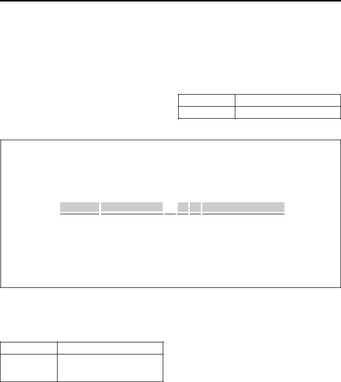
1.Park the vehicle on level ground and chock the front or rear wheels before lifting the vehicle.
2.Use covers on the vehicle body, seats, and floor to prevent damage and/or contaminations.
3.Disconnect the grounding cable from the battery before performing service operations.
This will prevent cable damage or burning due to shortcircuiting.
4.Raise the vehicle with a jack set against the axle or the frame.
5.Support the vehicle on chassis stands.
6.Handle brake fluid and antifreeze solution with great care.
Spilling these liquids on painted surfaces will damage the paint.
7.The use of the proper tool(s) and special tool(s) where specified is efficient, reliable, and safe service operations.
8.Always use genuine ISUZU replacement parts.
9.Discard used cotter pins, gasket, O-rings, oil seals, lock washers, and self-locking nuts at disassembly. Normal function of these parts cannot be guaranteed if they are reused.
10.Keep the disassembled parts neatly in groups. This will facilitate smooth and correct reassembly.
11.Keep fixing nuts and bolts separate.
Fixing nuts and bolts vary in hardness and design according to installation positions.
12.Clean all parts before inspection or reassembly.
13.Clean the oil ports and other openings with compressed air to make certain that they are free of dirt and obstructions.
14.Lubricate the rotating and sliding faces of all moving parts with oil or grease before installation.
15.Use the recommended liquid gasket to prevent leakage.
16.Be sure to tighten nuts and bolts to the specified torque, using a properly maintained torque wrench.
17.When service operation is completed, male a final check to be sure service has been done properly and problem has been corrected.
18.When removing or replacing parts that require refrigerant to the discharged from the Air conditioning system, be sure to use the ACR4 or equivalent to recover and recycle Refrigerant - 134a (HFC-134a), to promote the movement for the protection of the ozone layer covering the earth.
19.To assure safety, always slowly release air pressure from the air tanks before disconnecting pipes, hoses or other parts from any unit under pressure.
20.Prior to start the welding work, the following operations are required:
•Disconnect all connectors of electronic control unit.
•Disconnect battery ground terminal.
•Welding machine ground cable must be connected near the welding point.
•Turn off the all switches.

General Information 0A-3
Identification
Chassis Number/Engine Number Stamping Position
Chassis number
It is stamped on the front right-hand side face of the chassis side member.
MFW70ASH000101
Engine number (4HK1 Engine)
The engine number is stamped on the right side of the cylinder body.
LNWB0ASH000101
Engine number (6HF1 Engine)
The engine number (1) is stamped on the right side of the cylinder body.
1
MFW90ASH000101
Engine number (6HK1 Engine)
The engine number is stamped on the right side of the cylinder body.
MFW80ASH000401
Service Parts ID Plate
The service parts ID plate is attached to the passenger side lower dashboard.
The service parts ID plate has the following information;
•Vehicle identification number (VIN)
•Wheelbase dimensions
•Paint information
•Production options or special equipment installed on the vehicle at the factory

0A-4 General Information
Refer to the service parts ID plate when ordering replacement parts.
MFU8Z0SH043301
Option Code List
Option |
Option Description |
|
Code |
||
|
||
|
|
|
AJ3 |
Driver side air bag |
|
|
|
|
AK3 |
Front seat belt & shoulder |
|
with retractor |
||
|
||
|
|
|
AK5 |
Driver and passenger side air bag |
|
|
|
|
AU4 |
Automatic door lock |
|
|
|
|
A31 |
Power window - front & rear door |
|
|
|
|
A32 |
Power window - front door |
|
|
|
|
A56 |
Driver seat - air suspension |
|
|
|
|
A83 |
Vinyl seat with reclining |
|
|
|
|
BDM |
Power take off - transmission rear |
|
|
|
|
BFK |
Transfer TF56 |
|
|
|
|
BHW |
Power take off - engine rear, |
|
electromagnetic clutch |
||
|
||
|
|
|
BJR |
Brake adjuster - manual |
|
|
|
|
B02 |
South Africa equipment |
|
|
|
|
B03 |
Thailand equipment |
|
|
|
|
B04 |
Taiwan equipment |
|
|
|
|
B1S |
Parking brake drum - 8.5 inch |
|
|
|
|
B1T |
Parking brake drum - 10 inch |
|
|
|
|
B10 |
Malaysia equipment |
|
|
|
|
B12 |
Russia equipment |
|
|
|
|
B13 |
Australia equipment |
|
|
|
Option |
Option Description |
|
Code |
||
|
||
|
|
|
B14 |
Hong Kong equipment |
|
|
|
|
B3A |
Rear wheel parking brake - air |
|
control |
||
|
||
|
|
|
B30 |
Floor carpet - vinyl |
|
|
|
|
B84 |
Body side molding |
|
|
|
|
CB7 |
Colombia equipment |
|
|
|
|
CE4 |
Head lamp washer |
|
|
|
|
CGA |
Morocco equipment |
|
|
|
|
CJ6 |
Country - Ireland |
|
|
|
|
CK1 |
Pakistan equipment |
|
|
|
|
CL1 |
Kenya equipment |
|
|
|
|
CT6 |
Country - Italy |
|
|
|
|
CU9 |
Country - United Kingdom |
|
|
|
|
CV4 |
Country - Israel |
|
|
|
|
CX6 |
Country - New Zealand |
|
|
|
|
C13 |
Wiper with intermittent |
|
|
|
|
C2C |
Transmission oil cooler |
|
|
|
|
C2M |
Propeller shaft - P60 type |
|
|
|
|
C3N |
Final differential lock |
|
|
|
|
C3U |
Air suspension - high control |
|
|
|
|
C4M |
Air breather with flex hose |
|
|
|
|
C4Z |
Propeller shaft - P46 type |
|
|
|
|
C41 |
Heater & defroster |
|
|
|
|
C5K |
Hub lubrication - oil bath |
|
|
|
|
C5T |
Propeller shaft - P90 type |
|
|
|
|
C60 |
Manual air conditioning |
|
|
|
|
C65 |
Manual air conditioning |
|
without heater core |
||
|
||
|
|
|
C68 |
Automatic air conditioning |
|
|
|
|
DH2 |
O/S rear view mirror - long arm |
|
|
|
|
DL8 |
O/S rear view mirror - remote control |
|
with heated |
||
|
||
|
|
|
DNB |
O/S rear view mirror - pillar mounted |
|
|
|
|
D20 |
Assist side sun visor |
|
|
|
|
D31 |
Rear view mirror |
|
|
|
|
D37 |
Mirror - Outside rear view |
|
|
|
|
D6M |
User - export government |
|
|
|
|
D8T |
Iran equipment |
|
|
|
|
D94 |
Touch-up paint |
|
|
|

General Information 0A-5
Option |
Option Description |
|
Code |
||
|
||
|
|
|
EAK |
Disc wheel - 6 studs 19.5x6.75 |
|
(136-12) |
||
|
||
|
|
|
EBB |
Digital tachograph |
|
|
|
|
EBE |
Front under run protector |
|
|
|
|
ECF |
Speed limiter - 60km/h |
|
|
|
|
ECY |
Speed limiter - 70km/h |
|
|
|
|
EDG |
Header console - driver & assist |
|
|
|
|
EDH |
Round curtain rail |
|
|
|
|
EDW |
Speed limiter - 80km/h |
|
|
|
|
EDX |
Speed limiter - 85km/h |
|
|
|
|
EFE |
Regulation ECE R29 |
|
|
|
|
EFK |
Floor mat - vinyl mat Var.2 |
|
|
|
|
E09 |
Europe equipment |
|
|
|
|
E11 |
Mexico equipment |
|
|
|
|
E13 |
New Zealand equipment |
|
|
|
|
E2N |
Fuel pipe - steel |
|
|
|
|
E29 |
Auxiliary steps |
|
|
|
|
E40 |
Sleeper cab with mattress |
|
|
|
|
E46 |
Ecuador equipment |
|
|
|
|
FJC |
Disc wheel - 10 studs 20x8.50V |
|
(138-13) |
||
|
||
|
|
|
F59 |
Front stabilizer |
|
|
|
|
GH3 |
Saudi Arabia equipment |
|
|
|
|
GL6 |
Rear shock absorber |
|
|
|
|
GN1 |
Rear stabilizer |
|
|
|
|
G86 |
Limited slip differential - no spin |
|
|
|
|
JAQ |
Lighting system - Saudi Arabia |
|
|
|
|
JBF |
Tire - KD special |
|
|
|
|
JBZ |
Lighting system - Japanese standard |
|
|
|
|
JCA |
Anti-noise equipment - ECE R51.02 |
|
|
|
|
JDN |
Compartment - I/P assist side with lid |
|
|
|
|
JDP |
Compartment - I/P assist side without lid |
|
|
|
|
JE5 |
Anti-lock brake system |
|
|
|
|
J55 |
Brake system - heavy duty Var.1 |
|
|
|
|
J91 |
Trailer brake control |
|
|
|
|
KC5 |
Receptacle - accessory |
|
|
|
|
KE1 |
Chile equipment |
|
|
|
|
KF0 |
Fuel filter - low quality |
|
|
|
|
KG2 |
Generator 24V60A |
|
|
|
Option |
Option Description |
|
Code |
||
|
||
|
|
|
K30 |
Auto cruise |
|
|
|
|
K44 |
Generator 24V-90A |
|
|
|
|
K89 |
Generator 24V-50A |
|
|
|
|
M9A |
Owners manual - Not required |
|
|
|
|
NCR |
Memory system - Runnig condition |
|
|
|
|
NF7 |
Fuel tank 200L + 200L |
|
|
|
|
NJW |
Ireland KD special |
|
|
|
|
NMJ |
Speed limiter - 90km/h |
|
|
|
|
NMU |
Speed limiter - 100km/h |
|
|
|
|
NNR |
3 speaker system |
|
|
|
|
NT2 |
Emission system - Euro2 |
|
|
|
|
NT3 |
Emission system - Euro3 |
|
|
|
|
NT4 |
Emission system - Euro4 |
|
|
|
|
N02 |
Fuel tank 100L - frame side mount |
|
|
|
|
N05 |
Fuel tank cap with key lock |
|
|
|
|
N19 |
Fuel tank - 140L frame side |
|
|
|
|
N20 |
Fuel tank 200L - frame side mount |
|
|
|
|
N79 |
Spare disc wheel |
|
|
|
|
PM1 |
Rear hook - double |
|
|
|
|
PP7 |
Pintle hook |
|
|
|
|
PR2 |
Driving position - wide leg space |
|
|
|
|
PS7 |
Air dryer |
|
|
|
|
PT1 |
Disc wheel - 8 studs 22.5x6.75 |
|
(145-11) |
||
|
||
|
|
|
PT6 |
Thailand KD special |
|
|
|
|
P10 |
Spare tire carrier - frame rear mount |
|
|
|
|
P13 |
Spare tire carrier - frame side mount |
|
|
|
|
P38 |
Tire delete |
|
|
|
|
QM8 |
Disc wheel - 10 studs 22.5 x 8.25 |
|
(165-13) |
||
|
||
|
|
|
Q47 |
Disc wheel - 8 studs 20x6.50T |
|
(145-10) |
||
|
||
|
|
|
Q87 |
Disc wheel - 10 studs 22.5x7.50 |
|
(162-12) |
||
|
||
|
|
|
Q5T |
Turbo - conventional |
|
|
|
|
Q50 |
Disc wheel - 8 studs 20x6.50T |
|
(152-11) |
||
|
||
|
|
|
Q54 |
Disc wheel - 8 studs 20x7.00T |
|
(162-12) |
||
|
||
|
|
|
Q58 |
Disc wheel - 10 studs 20x7.00T |
|
|
|

0A-6 General Information
Option |
Option Description |
|
Code |
||
|
||
|
|
|
Q62 |
Disc wheel - 8 studs 20x7.50V |
|
(165-13) |
||
|
||
|
|
|
Q64 |
Disc wheel - 10 studs 20 x 7.50V |
|
|
|
|
Q87 |
Disc wheel - 10 studs 22.5x7.50 |
|
(162-12) |
||
|
||
|
|
|
RC4 |
Dump control lever |
|
|
|
|
RC5 |
Tool box with key lock |
|
|
|
|
RE3 |
Spare tire fixing |
|
|
|
|
RE9 |
Clutch - 15 inch single plate |
|
strap drive |
||
|
||
|
|
|
RDV |
4HK1-TCC engine |
|
|
|
|
RJS |
4HK1-TCS engine |
|
|
|
|
RQZ |
G.V.W. - 8.0-11.0 ton |
|
|
|
|
RRA |
G.V.W. - 11.0-14.0 ton |
|
|
|
|
RR9 |
O/S rear view mirror - under |
|
|
|
|
RSA |
Manual transmission - MZZ6W |
|
|
|
|
RSW |
Manual transmission - MZX6P |
|
|
|
|
RSZ |
Manual transmission - MZW6P |
|
|
|
|
RWE |
Chevrolet brand |
|
|
|
|
R32 |
KD frame |
|
|
|
|
R46 |
Spare tire & disc wheel |
|
|
|
|
R9A |
Service cab with electric |
|
|
|
|
R9B |
Service cab without electric |
|
|
|
|
R9C |
Deletion - service cab with electric |
|
|
|
|
R9D |
Deletion - service cab without electric |
|
|
|
|
R9E |
Service cab conversion with electric |
|
|
|
|
R9F |
Deletion - service cab conversion |
|
without electric |
||
|
||
|
|
|
R9Z |
Thailand localization spec. |
|
|
|
|
SAQ |
Front suspension - multi leaf spring |
|
|
|
|
SAR |
Front suspension - taper leaf spring |
|
|
|
|
SAS |
Rear suspension - multi leaf spring |
|
|
|
|
SAU |
Rear helper suspension - taper leaf |
|
spring |
||
|
||
|
|
|
SAY |
Standard cab |
|
|
|
|
SAZ |
Ventilator & defroster |
|
|
|
|
SBB |
Disc wheel - 8 studs 20x6.00S |
|
(135-10) |
||
|
||
|
|
|
SBG |
Disc wheel - 6 studs 17.5x6.00 |
|
(135-9) |
||
|
||
|
|
Option |
Option Description |
|
Code |
||
|
||
|
|
|
SDF |
Room lamp with all door switch |
|
|
|
|
SDH |
Fuel tank 400L |
|
|
|
|
SDK |
Cab suspension - semi floating type |
|
|
|
|
SDP |
Disc wheel - 8 studs 20x7.00T |
|
(152-12) |
||
|
||
|
|
|
SEG |
Disc wheel - 8 studs 205x7.50V |
|
(130-13) |
||
|
||
|
|
|
SFC |
Disc wheel - 6 studs 17.5x6.75 |
|
(137-10) |
||
|
||
|
|
|
SFT |
Electric outlet - one |
|
|
|
|
SGA |
Front under spoiler delete |
|
|
|
|
SGX |
Vietnam equipment |
|
|
|
|
SG4 |
Tire inflator device |
|
|
|
|
SG7 |
Disc wheel - 6 studs 16x6.00GS |
|
(135-9) |
||
|
||
|
|
|
SH5 |
Power take off - transmission side |
|
without lever |
||
|
||
|
|
|
SJA |
Driver seat - Isringhausen |
|
|
|
|
SKU |
Disc wheel - 8 studs 22.5x7.50 |
|
(162-13) |
||
|
||
|
|
|
SKV |
Disc wheel - 8 studs 22.5 x 8.25 |
|
(165-13) |
||
|
||
|
|
|
SK4 |
Engine overrun buzzer |
|
|
|
|
SLB |
Front bumper with headlamp |
|
|
|
|
SLC |
Lighting system - ECE |
|
|
|
|
SLK |
Anti-noise equipment - ECE |
|
|
|
|
SMS |
Rear bumper - steel wide |
|
|
|
|
SP9 |
Assist seat without center seat |
|
|
|
|
SR6 |
Rearward double tire |
|
|
|
|
SV6 |
Power take off control |
|
|
|
|
SY8 |
Spare tire carrier - lifting type |
|
|
|
|
TAF |
O/S rear view mirror - under & side |
|
under |
||
|
||
|
|
|
TAK |
Anti-noise equipment - Var.2 |
|
|
|
|
TAZ |
Driver seat - rigid without arm rest |
|
|
|
|
TDU |
Brake regulation - ADR |
|
|
|
|
TDV |
Brake regulation - ECE |
|
|
|
|
TEC |
Roof marker lamp |
|
|
|
|
TEE |
Disc wheel - 8 studs 19.5x6.75 |
|
(147-12) |
||
|
||
|
|
|
TFD |
Cab all painting |
|
|
|

General Information 0A-7
Option |
Option Description |
|
Code |
||
|
||
|
|
|
TFN |
Driver’s seat belt with pre-tension |
|
reducer |
||
|
||
|
|
|
TGL |
Anti corrosion package |
|
|
|
|
TM1 |
Battery - 80D26L |
|
|
|
|
TR6 |
Headlamp leveling system - manual |
|
|
|
|
TR7 |
Headlamp leveling system - automatic |
|
|
|
|
TT5 |
Halogen headlamp |
|
|
|
|
TT6 |
High intensity discharge headlamp |
|
|
|
|
T1A |
Injection pump Q set - special |
|
+5%Q |
||
|
||
|
|
|
T62 |
Battery - dry |
|
|
|
|
T64 |
Battery delete |
|
|
|
|
T79 |
Rear fog lamp |
|
|
|
|
T87 |
Cornering lamp |
|
|
|
|
T96 |
Front fog lamp |
|
|
|
|
UC1 |
Speedometer - miles per hour (MPH) |
|
|
|
|
UC9 |
TachographKienzle |
|
|
|
|
UF3 |
Map lamp |
|
|
|
|
UG3 |
Engine oil temperature gauge |
|
|
|
|
UL5 |
Radio delete |
|
|
|
|
UT3 |
AM/FM radio with CD player |
|
|
|
|
U01 |
Roof marker - 5 lamps |
|
|
|
|
U18 |
Speedometer - kilometer |
|
|
|
|
U69 |
AM/FM radio |
|
|
|
|
U95 |
2 speaker system |
|
|
|
|
VG7 |
Front bumper reinforcement |
|
- heavy duty |
||
|
||
|
|
|
VP1 |
Front under spoiler |
|
|
|
|
VR7 |
Two eye rear hook |
|
|
|
|
VTK |
Owners manual - Arabic language |
|
|
|
|
VTL |
Owners manual - French language |
|
|
|
|
VTS |
Owners manual - Spanish language |
|
|
|
|
VT7 |
Owners manual - English language |
|
|
|
|
VZA |
VIN model year - 2010 |
|
|
|
|
VZB |
VIN model year - 2011 |
|
|
|
|
V22 |
Radiator grille - chrome |
|
|
|
|
V4F |
Chassis for fire car |
|
|
|
|
V76 |
Hook - tow |
|
|
|
|
WB7 |
Electrical horn |
|
|
|
Option |
Option Description |
|
Code |
||
|
||
|
|
|
WC7 |
Tachograph - 140km/h |
|
|
|
|
WF6 |
Clutch - 14 inch single plate |
|
strap drive |
||
|
||
|
|
|
WG3 |
Brake system - heavy duty Var.2 |
|
|
|
|
WH2 |
Spare tire - front tire |
|
|
|
|
WJ7 |
Cautions - Arabian |
|
|
|
|
WJ8 |
Cautions - French |
|
|
|
|
WL5 |
Inspection lamp |
|
|
|
|
WM3 |
Interior trim - full trimming |
|
|
|
|
WV2 |
Automatic cab tilt |
|
|
|
|
WX8 |
Shift control - assister |
|
|
|
|
W02 |
Highland zone package |
|
|
|
|
W1G |
Final drive gear ratio - 6.143 (43/7) |
|
14.5 inch hypoid |
||
|
||
|
|
|
W1H |
Final drive gear ratio - 5.571 (39/7) |
|
14.5 inch hypoid |
||
|
||
|
|
|
W1J |
Final drive gear ratio - 6.500 (39/6) |
|
14.5 inch hypoid |
||
|
||
|
|
|
W1K |
Final drive gear ratio - 6.833 (41/6) |
|
14.5 inch hypoid |
||
|
||
|
|
|
W1L |
Final drive gear ratio - 6.500 (39/6) |
|
16.5 inch hypoid |
||
|
||
|
|
|
W1R |
Final drive gear ratio - 6.143 (43/7) |
|
15.5 inch hypoid |
||
|
||
|
|
|
W1T |
Final drive gear ratio - 6.500 (39/6) |
|
15.5 inch hypoid |
||
|
||
|
|
|
W1U |
Final drive gear ratio - 4.875 (39/8) |
|
14.5 inch hypoid |
||
|
||
|
|
|
W12 |
Front locking hub - manual |
|
|
|
|
W14 |
Deluxe cab |
|
|
|
|
W16 |
Cab suspension - full floating |
|
|
|
|
W18 |
Transfer TF36 |
|
|
|
|
W20 |
Disc wheel special painted (white) |
|
|
|
|
W3B |
Final drive gear ratio - 5.571 (39/7) |
|
16.5 inch hypoid |
||
|
||
|
|
|
W3D |
Final drive gear ratio - 4.875 (39/8) |
|
18.5 inch hypoid |
||
|
||
|
|
|
W3F |
Final drive gear ratio - 6.167 (37/6) |
|
18.5 inch hypoid |
||
|
||
|
|
|
W3G |
Final drive gear ratio - 6.667 (40/6) |
|
18.5 inch hypoid |
||
|
||
|
|
|
W3K |
Final drive gear ratio - 5.571 (39/7) |
|
15.5 inch hypoid |
||
|
||
|
|
0A-8 General Information
Option |
Option Description |
|
Code |
||
|
||
|
|
|
W3L |
Final drive gear ratio - 6.143 (43/7) |
|
16.5 inch hypoid |
||
|
||
|
|
|
W3M |
Final drive gear ratio - 5.125 (41/8) |
|
18.5 inch hypoid |
||
|
||
|
|
|
W3N |
Final drive gear ratio - 4.556 (41/9) |
|
18.5 inch hypoid |
||
|
||
|
|
|
W3P |
Final drive gear ratio - 5.125 (41/8) |
|
16.5 inch hypoid |
||
|
||
|
|
|
W3S |
Final drive gear ratio - 5.857 (41/7) |
|
15.5 inch hypoid |
||
|
||
|
|
|
W3U |
Final drive gear ratio - 7.167 (43/6) |
|
17.5 inch hypoid |
||
|
||
|
|
|
W3X |
Final drive gear ratio - 6.429 (45/7) |
|
17.5 inch hypoid |
||
|
||
|
|
|
W3Y |
Final drive gear ratio - 6.143 (43/7) |
|
17.5 inch hypoid |
||
|
||
|
|
|
W3Z |
Final drive gear ratio - 5.571 (39/7) |
|
17.5 inch hypoid |
||
|
||
|
|
|
W4A |
Final drive gear ratio - 5.125 (41/8) |
|
17.5 inch hypoid |
||
|
||
|
|
|
W4B |
Final drive gear ratio - 4.875 (39/8) |
|
17.5 inch hypoid |
||
|
||
|
|
|
W4C |
Final drive gear ratio - 4.556 (41/9) |
|
17.5 inch hypoid |
||
|
||
|
|
|
W4F |
Final drive gear ratio - 5.125 (41/8) |
|
14.5 inch hypoid |
||
|
||
|
|
|
W4H |
Final drive gear ratio - 5.125 (41/8) |
|
15.5 inch hypoid |
||
|
||
|
|
|
W4T |
Final drive gear ratio - 4.333 (39/9) |
|
18.5 inch hypoid |
||
|
||
|
|
|
W4W |
Final drive gear ratio - 6.833 (41/6) |
|
17.5 inch hypoid |
||
|
||
|
|
|
W4X |
Final drive gear ratio - 4.333 (39/9) |
|
14.5 inch hypoid |
||
|
||
|
|
|
W5M |
Final drive gear ratio - 4.100 (41/10) |
|
14.5 inch hypoid |
||
|
||
|
|
|
W5V |
Final drive gear ratio - 6.833 (41/6) |
|
16.5 inch hypoid Rockwell |
||
|
||
|
|
|
W5Z |
Final drive gear ratio - 4.89 (44/9) |
|
18.0 inch hypoid Rockwell |
||
|
||
|
|
|
W6A |
Final drive gear ratio - 5.38 (43/8) |
|
18.0 inch hypoid Rockwell |
||
|
||
|
|
|
W6B |
Final drive gear ratio - 5.63 (45/8) |
|
18.0 inch hypoid Rockwell |
||
|
||
|
|
|
W6C |
Final drive gear ratio - 6.14 (43/7) |
|
18.0 inch hypoid Rockwell |
||
|
||
|
|
Option |
Option Description |
|
Code |
||
|
||
|
|
|
W6M |
Final drive gear ratio - 6.43 (45/7) |
|
18.0 inch hypoid Rockwell |
||
|
||
|
|
|
W6N |
Final drive gear ratio - 6.83 (41/6) |
|
18.0 inch hypoid Rockwell |
||
|
||
|
|
|
W6R |
Final drive gear ratio - 4.30 (43/10) |
|
18.0 inch hypoid Rockwell |
||
|
||
|
|
|
W6S |
Final drive gear ratio - 6.14 (43/7) |
|
15.0 inch hypoid Rockwell |
||
|
||
|
|
|
W66 |
Disc wheel with step |
|
|
|
|
W71 |
Cab suspension - rigid type |
|
|
|
|
W8C |
Final drive gear ratio - 4.56 (41/9) |
|
18.0 inch hypoid Rockwell |
||
|
||
|
|
|
W8D |
Final drive gear ratio - 6.43 (45/7) |
|
15.0 inch hypoid Rockwell |
||
|
||
|
|
|
W8F |
Final drive gear ratio - 4.555 (41/9) |
|
14.5 inch hypoid |
||
|
||
|
|
|
W8L |
Final drive gear ratio - 6.83 (41/6) |
|
15.0 inch hypoid Rockwell |
||
|
||
|
|
|
X5J |
Manual transmission - MLD6Q |
|
|
|
|
X7W |
Manual transmission - MLD6S |
|
|
|
|
X9C |
Transmission - manual |
|
|
|
|
X9D |
Transmission - automatic |
|
|
|
|
YC4 |
Injection pump - high altitude |
|
compensator, aneroid type |
||
|
||
|
|
|
YK3 |
Rearward single tire |
|
|
|
|
YM9 |
Reversing warning buzzer |
|
|
|
|
YN1 |
Caution - Spanish |
|
|
|
|
YS1 |
O/S rear view mirror - flat type |
|
|
|
|
YT9 |
Pakistan KD special |
|
|
|
|
Y2C |
Manual transmission - MLD6W |
|
|
|
|
Y21 |
Light duty package truck |
|
|
|
|
Y3A |
Manual transmission |
|
- Fuller FS8209 |
||
|
||
|
|
|
Y3B |
Automatic transmission |
|
- Allison MD3560P |
||
|
||
|
|
|
Y4F |
Automatic transmission |
|
- Allison LCT2000 |
||
|
||
|
|
|
Y4G |
Automatic transmission |
|
- Allison MD3060P |
||
|
||
|
|
|
Y4V |
Manual transmission |
|
- Fuller FSO5206B |
||
|
||
|
|
|
Y48 |
Heavy duty package truck |
|
|
|
|
Y5D |
Manual transmission - ZF 6S1000 |
|
|
|

General Information 0A-9
Option |
Option Description |
|
Code |
||
|
||
|
|
|
Y5E |
Manual transmission - ZF 9S1110 |
|
|
|
|
Z05 |
Brake system - air over hydraulic |
|
dual circuit |
||
|
||
|
|
|
Z06 |
Brake system - full air dual circuit |
|
|
|
|
Z1V |
Equipment - additional key |
|
|
|
|
01D |
KD package - South Africa |
|
|
|
|
01R |
Tire - front & rear 8.25-20-14 lug |
|
|
|
|
02E |
KD package - Taiwan |
|
|
|
|
05R |
Tire - front & rear 8.25R20-14 rib |
|
|
|
|
09X |
Tire - front 8.25-20-14 rib, |
|
rear 8.25-20-14 lug |
||
|
||
|
|
|
1D7 |
6HF1-TCN engine |
|
|
|
|
1D9 |
6HF1-TCC engine |
|
|
|
|
10T |
Tire - front & rear 9.00-20-14 rib |
|
|
|
|
10X |
Tire - front 9.00-20-14 rib, |
|
rear 9.00-20-14 lug |
||
|
||
|
|
|
11X |
Tire - front 10.00-20-14 rib, |
|
rear 10.00-20-14 lug |
||
|
||
|
|
|
12X |
Tire - front 10.00-20-16 rib, |
|
rear 10.00-20-16 lug |
||
|
||
|
|
|
15N |
Tire - front & rear 9R22.5-14 rib |
|
|
|
|
155 |
Interior color - Charcoal gray |
|
|
|
|
2G0 |
Singapore equipment |
|
|
|
|
20D |
Thailand KD deletion parts |
|
|
|
|
21R |
Tire - front & rear 9.00-20-14 lug |
|
|
|
|
25R |
Tire - front & rear 9.00R20-14 rib |
|
|
|
|
27X |
Tire - front 11.00-20-16 rib, |
|
rear 11.00-20-16 lug |
||
|
||
|
|
|
30T |
Tire - front & rear 10.00-20-14 rib |
|
|
|
|
34W |
Wheel base 3,400mm |
|
|
|
|
35N |
Tire - front & rear 10R22.5-14 rib |
|
|
|
|
36W |
Wheel base 3,600mm |
|
|
|
|
37W |
Wheel base 3,700mm |
|
|
|
|
38W |
Wheel base 3,800mm |
|
|
|
|
39W |
Wheel base 3,900mm |
|
|
|
|
40S |
Tire - front & rear 8.25-16-14 rib |
|
|
|
|
40T |
Tire - front & rear 10.00-20-16 rib |
|
|
|
|
40W |
Wheel base 4,000mm |
|
|
|
|
41R |
Tire - front & rear 10.00-20-14 lug |
|
|
|
|
41W |
Wheel base 4,100mm |
|
|
|
Option |
Option Description |
|
|
Code |
|
||
|
|
|
|
|
|
|
|
42W |
Wheel base 4,200mm |
|
|
|
|
|
|
43P |
Tire - front & rear 9R22.5-14 |
|
|
|
|
|
|
43W |
Wheel base 4,300mm |
|
|
|
|
|
|
45N |
Tire - front & rear 11R22.5-14 rib |
|
|
|
|
|
|
45P |
Tire - front & rear 275/70R22.5 |
|
|
|
|
|
|
45R |
Tire - front & rear 10.00R20-14 rib |
|
|
|
|
|
|
46W |
Wheel base 4,600mm |
|
|
|
|
|
|
48W |
Wheel base 4,800mm |
|
|
|
|
|
|
49W |
Wheel base 4,900mm |
|
|
|
|
|
|
49P |
Tire - front & rear 8.25R20-14 |
|
|
exp block |
|
|
|
|
|
|
|
|
|
|
|
5D9 |
Tire - front & rear |
|
|
295/80R22.5-152/148K rib/lug |
|
||
|
|
||
|
|
|
|
5E0 |
Tire - front & rear |
|
|
295/80R22.5-152/148J rib |
|
||
|
|
||
|
|
|
|
5E1 |
Tire - front & rear 10R22.5-14 |
|
|
|
|
|
|
5G2 |
Tire - front 295/80R22.5, |
|
|
rear 11R22.5-16 |
|
|
|
|
|
|
|
|
|
|
|
5H1 |
Tire - front 10.00-20-16 rib, |
|
|
rear 10.00-20-16 lug |
|
|
|
|
|
|
|
|
|
|
|
5J6 |
Tire - front 9.5R17.5 129/127L rib, |
|
|
rear 9.5R17.5 129/127L traction |
|
||
|
|
||
|
|
||
5J7 |
Tire - front & rear 11R22.5 148/145L |
||
rib |
|
|
|
|
|
|
|
|
|
|
|
5J8 |
Tire - front & rear 245/70R19.5 rib |
|
|
|
|
|
|
5J9 |
Tire - front & rear 235/75R17.5 rib |
|
|
|
|
|
|
5K0 |
Tire - front & rear 265/70R19.5 rib |
|
|
|
|
||
5K4 |
Tire - front & rear 11R22.5 148/145K |
||
rib/lug |
|
|
|
|
|
|
|
|
|
||
5K5 |
Tire - front & rear 12R22.5 152/148K |
||
rib/lug |
|
|
|
|
|
|
|
|
|
|
|
5L1 |
Tire - front & rear 12.00R20-18 |
|
|
|
|
|
|
5L4 |
Tire - front & rear 275/70R22.5 |
|
|
148/145M rib |
|
|
|
|
|
|
|
|
|
|
|
5L7 |
Tire - front & rear 9.00R-20-14 |
|
|
exp lug |
|
|
|
|
|
|
|
|
|
|
|
5L8 |
Tire - front & rear 10.00R-20-16 lug |
|
|
|
|
|
|
5N5 |
Tire - front & rear |
265/70R19.5 |
140/ |
138M rib (BS brand) |
|
|
|
|
|
|
|
|
|
|
|
5N6 |
Tire - front & rear |
235/75R17.5 |
132/ |
130M rib (BS brand) |
|
|
|
|
|
|
|
|
|
|
|
5P0 |
Tire - front & rear |
235/75R17.5 |
132/ |
130M rib (BS brand) |
|
|
|
|
|
|
|
|
|
|
|

0A-10 General Information
Option |
Option Description |
|
Code |
||
|
||
|
|
|
5P1 |
Tire - front 295/80R22.5, |
|
rear 11R22.5-16 (6x2, BS brand) |
||
|
||
|
|
|
5P2 |
Tire - front 295/80R22.5, |
|
rear 11R22.5-16 (BS brand) |
||
|
||
|
|
|
5P3 |
Tire - front & rear 10R22.5-14 |
|
exp rib/lug (BS brand) |
||
|
||
|
|
|
5P6 |
Tire - front & rear 225/70R19.5 |
|
|
|
|
5P7 |
Tire - front & rear 8.25R16 128/126L |
|
exp rib/lug |
||
|
||
|
|
|
50W |
Wheel base 5,000mm |
|
|
|
|
51R |
Tire - front & rear 10.00-20-16 lug |
|
|
|
|
51W |
Wheel base 5,100mm |
|
|
|
|
517 |
Body color - AL. gray |
|
|
|
|
53W |
Wheel base 5,300mm |
|
|
|
|
538 |
Body color - Tool-IPEC yellow |
|
|
|
|
55N |
Tire - front & rear 11R22.5-16 rib |
|
|
|
|
55P |
Tire - front & rear 295/80R22.5 |
|
152/148M rib |
||
|
||
|
|
|
55R |
Tire - front & rear 10.00R20-16 rib |
|
|
|
|
55W |
Wheel base 5,500mm |
|
|
|
|
58N |
Tire - front & rear 11.00R20-16 rib |
|
|
|
|
58W |
Wheel base 5,800mm |
|
|
|
|
59W |
Wheel base 5,900mm |
|
|
|
|
6DY |
Rear under run protector |
|
|
|
|
6EP |
HSA system |
|
|
|
|
6HF |
KD preparatory package |
|
|
|
|
6KK |
Horn - heavy duty (dual) |
|
|
|
|
6ND |
OK window |
|
|
|
|
6NF |
Remote control door lock |
|
|
|
|
6PH |
LSPV - Load sensing proportioning |
|
valve |
||
|
||
|
|
|
6SZ |
Power take off - flywheel |
|
|
|
|
6UC |
Fluorescent lamp |
|
|
|
|
6UH |
O/S rear view mirror - assist side short |
|
stay |
||
|
||
|
|
|
6VE |
O/S rear view mirror - door mount |
|
|
|
|
6WX |
Floor mat - vinyl |
|
|
|
|
6XH |
ASR system |
|
|
|
|
60W |
Wheel base 6,000mm |
|
|
|
|
609 |
Body color - FT orange |
|
|
|
Option |
Option Description |
|
Code |
||
|
||
|
|
|
61P |
Tire - front & rear 225/90R17.5 |
|
|
|
|
63E |
KD package - Italy |
|
|
|
|
63W |
Wheel base 6,300mm |
|
|
|
|
64E |
KD package - Vietnam |
|
|
|
|
64N |
Tire - front & rear 8.25R20-14 rib |
|
|
|
|
65W |
Wheel base 6,500mm |
|
|
|
|
668 |
Body color - Purplish blue |
|
|
|
|
681 |
Body color - Geranium red |
|
|
|
|
695 |
Body color - Dark blue |
|
|
|
|
7BC |
Assist seat with center seat |
|
|
|
|
7DM |
Tuner band - Latin America |
|
|
|
|
7FL |
Seat material - cloth |
|
|
|
|
7HZ |
Rear bumper |
|
|
|
|
7KC |
Immobilizer system |
|
|
|
|
7NY |
Multi information display |
|
|
|
|
7SV |
O/S rear view mirror - heated |
|
|
|
|
7TV |
KD preparatory package |
|
|
|
|
70T |
Tire - front & rear 11.00-20-14 rib |
|
|
|
|
71R |
Tire - front & rear 11.00-20-14 lug |
|
|
|
|
71S |
Tire - front & rear 7.50-20-12 lug |
|
|
|
|
71W |
Wheel base 7,100mm |
|
|
|
|
729 |
Body color - Arc white |
|
|
|
|
736 |
Body color - Cardinal red |
|
|
|
|
78N |
Tire - front & rear 8.25R16 |
|
|
|
|
79R |
Tire - front & rear 11.00R20-14 |
|
|
|
|
8AA |
Good quality ethylene glycol |
|
antifreeze 50% |
||
|
||
|
|
|
8AC |
Good quality ethylene glycol |
|
antifreeze 30% |
||
|
||
|
|
|
8EJ |
Battery - 65D23L |
|
|
|
|
8GF |
Transmission with Smoother |
|
|
|
|
8GJ |
Transmission without Smoother |
|
|
|
|
8JM |
Diesel particulate diffuser |
|
|
|
|
8LF |
Rear window glass |
|
|
|
|
8LX |
Ash tray - assist side |
|
|
|
|
8MA |
Battery 115E41L |
|
|
|
|
8MH |
Fuel tank 370L |
|
|
|
|
8ML |
O/S rear view mirror - middle arm |
|
|
|

General Information 0A-11
Option |
Option Description |
|
Code |
||
|
||
|
|
|
8MV |
O/S rear view mirror - extended long |
|
arm |
||
|
||
|
|
|
8NG |
Decal - vehicle & pet name |
|
|
|
|
8NH |
Decal - pet name |
|
|
|
|
8NV |
Bio diesel fuel B10 |
|
|
|
|
80L |
6HK1-TCS engine |
|
|
|
|
80R |
Tire - front & rear 11.00-20-16 rib |
|
|
|
|
800 |
Body color - In white |
|
|
|
|
807 |
Body color - Woodland green |
|
|
|
|
81L |
6HK1-TCC engine |
|
|
|
|
81R |
Tire - front & rear 11.00-20-16 lug |
|
|
|
|
81U |
Tire - front & rear 8.25-16-14 lug |
|
|
|
|
812 |
Body color - Wheatland yellow |
|
|
|
|
82L |
6HK1-TCN engine |
|
|
|
|
829 |
Body color - Sahara beige |
|
|
|
|
83N |
Tire - front & rear 9.5R17.5 |
|
|
|
|
84D |
Colombia Var.2 |
|
|
|
|
85N |
Tire - front & rear 11R22.5-16 |
|
|
|
|
85R |
Tire - front & rear 11.00R20-16 rib |
|
|
|
|
85U |
Tire - front & rear 8.25R16-14 rib |
|
|
|
|
87N |
Tire - front & rear 10.00R20-14PR rib |
|
|
|
|
89N |
Tire - front & rear 9.00R20-14PR rib |
|
|
|
|
89R |
Tire - front & rear 11.00R20-16PR |
|
|
|
|
89T |
Tire - front & rear 11.00R20-16 |
|
|
|
|
890 |
Body color - Marine blue |
|
|
|
|
90S |
Tire - front & rear 8.25-20-14 rib |
|
|
|
|
904 |
Body color - golden yellow |
|
|
|
|
91D |
KD package - Philippine Var.2 |
|
|
|
|
915 |
Body color - fire red |
|
|
|
|
92N |
Tire - front & rear 8.25R16-14PR rib |
|
|
|
|
93N |
Tire - front 12.00R20-18, |
|
rear 12.00R20-18 lug |
||
|
||
|
|
|
94K |
Tire - front & rear 10.00R20-16 |
|
|
|
|
94N |
Tire - front & rear 12.00R20-16 |
|
|
|
|
944 |
Body color - Highway orange |
|
|
|
|
95D |
KD package - Ireland |
|
|
|
|
951 |
Body color - arc white |
|
|
|
|
97N |
Tire - front 295/80R22.5, |
|
rear 11R22.5-16 |
||
|
||
|
|
Option |
Option Description |
|
Code |
||
|
||
|
|
|
982 |
Body color - Polar white |
|
|
|
|
989 |
Body color - Sunbelt green |
|
|
|
|
99D |
KD package - United Kingdom |
|
|
|
|
99N |
Tire - front & rear 11R22.5-16 |
|
|
|
|
909 |
Body color - middle bronze green |
|
|
|
|
919 |
Body color - olive drab |
|
|
|
|
999 |
Body color - trans blue |
|
|
|
Vehicle Identification Number (VIN)
The ID plate indicates the vehicle identification number (VIN).
This single number contains multiple pieces of information including the vehicle and engine model codes as shown below.

0A-12 General Information
Type 1
J A L F R R 3 4 L 8 7 0 0 0 0 0 1
1 2 3 4 5 6
MFW80ASF000201
Legend |
|
|
|
|
|
||
1. World manufacturer identifier (WMI) |
|
|
|
|
|||
2. |
Vehicle model code |
|
|
|
|
||
3. |
Engine code |
|
|
|
|
|
|
4. Wheel base code |
|
|
|
|
|
||
5. |
Model year code |
|
|
|
|
|
|
6. |
Chassis number |
|
|
|
|
|
|
|
|
|
|
|
|
||
1. World manufacturer identifier (WMI) |
|
4. Wheel base code |
|
||||
|
|
|
|
|
|
|
|
|
Code |
|
|
|
Code |
|
|
|
|
|
|
|
|
|
|
|
|
|
ISUZU BRAND |
|
H |
|
3,201 - 3,500 mm |
|
JAL |
|
Medium & Heavy Duty |
|
|
(126.02 - 137.80 in) |
|
|
|
|
|
|
|||
|
|
|
Incomplete Vehicle |
|
|
|
|
|
|
|
|
J |
|
3,501 - 3,800 mm |
|
|
|
|
|
|
|
||
2. Vehicle model code |
|
|
|
(137.83 - 149.61 in) |
|||
|
|
|
|
||||
|
|
|
|
|
|||
|
|
K |
|
3,801 - 4,100 mm |
|||
|
|
|
|
|
|
||
|
Code |
|
|
|
|
(149.65 - 161.42 in) |
|
|
|
|
|
|
|
||
|
|
|
|
|
|
|
|
|
FRR |
|
4x2 Truck FRR model |
|
|
|
|
|
|
|
L |
|
4,101 - 4,400 mm |
||
|
|
|
|
|
|
(161.46 - 173.23 in) |
|
|
FSR |
|
4x2 Truck FSR model |
||||
|
|
|
|
|
|||
|
|
|
|
|
|
||
|
|
|
|
|
|
|
4,401 - 4,700 mm |
|
FTR |
|
4x2 Truck FTR model |
|
M |
|
|
|
|
|
|
(173.27 - 185.04 in) |
|||
|
|
|
|
|
|
|
|
|
FVR |
|
4x2 Truck FVR model |
|
|
|
|
|
|
|
|
|
|
||
|
|
|
N |
|
4,701 - 5,000 mm |
||
|
|
|
|
|
|
||
|
FVZ |
|
6x4 Truck FVZ model |
|
|
||
|
|
|
|
(185.08 - 196.85 in) |
|||
|
|
|
|
|
|||
|
|
|
|
|
|
|
|
|
FVM |
|
6x2 Truck FVM model |
|
|
|
|
|
|
|
P |
|
5,001 - 5,300 mm |
||
|
|
|
|
|
|
(196.89 - 208.66 in) |
|
|
GVR |
|
4x2 Tractor GVR model |
||||
|
|
|
|
|
|||
|
|
|
|
|
|
||
|
|
|
|
|
|
|
5,301 - 5,600 mm |
|
FSS |
|
4x4 Truck FSS model |
|
7 |
|
|
|
|
|
|
(208.70 - 220.47 in) |
|||
|
|
|
|
|
|
|
|
|
FTS |
|
4x4 Truck FTS model |
|
|
|
|
|
|
|
|
|
|
||
|
|
|
R |
|
5,601 - 5,900 mm |
||
|
|
|
|
|
|
||
|
|
|
|
|
|
||
|
|
|
|
|
|
(220.51 - 232.28 in) |
|
3. Engine code |
|
|
|
|
|||
|
|
|
|
|
|||
|
|
S |
|
5,901 - 6,200 mm |
|||
|
|
|
|
|
|
||
|
Code |
|
|
|
|
||
|
|
|
|
|
(232.32 - 244.09 in) |
||
|
|
|
|
|
|
|
|
|
34 |
|
6HK1 Engine |
|
|
|
|
|
|
|
T |
|
6,201 - 6,500 mm |
||
|
|
|
|
|
|
||
|
86 |
|
6HF1 Engine |
|
|
(244.13 - 255.91 in) |
|
|
|
|
|
|
|||
|
|
|
|
|
|
|
|
|
|
|
|
|
|
|
|
|
90 |
|
4HK1 Engine |
|
|
|
|
|
|
|
|
|
|
|
|

General Information 0A-13
|
|
|
5. Model year code |
|
||
Code |
|
|
||||
|
|
|
|
|
||
U |
6,501 - 6,800 mm |
|
Code |
|
|
|
|
|
|
|
|||
(255.94 - 267.72 in) |
|
|
|
|
||
|
8 |
|
2008MY |
|||
|
|
|
||||
|
|
|
|
|
|
|
|
6,801 - 7,100 mm |
|
|
|
|
|
V |
|
9 |
|
2009MY |
||
(267.76 - 279.53 in) |
|
|
|
|
||
|
|
A |
|
2010MY |
||
|
|
|
|
|||
W |
7,101 - 7,400 mm |
|||||
|
|
|
|
|||
|
B |
|
2011MY |
|||
(279.57 - 291.34 in) |
|
|
||||
|
|
|
|
|
||
|
|
|
|
|
|
|
Type 2 |
|
|
|
|
|
|
J A L |
|
H |
|
5 |
|
K |
|
1 |
|
6 |
|
|
|
8 |
|
7 |
|
7 0 0 0 0 1 |
|
|
|
|
|
|
|
|
|
|
|
|
|
|
|
|
|
|
|
|
|
1 |
2 |
|
3 |
|
4 |
|
5 |
|
6 |
7 |
8 |
|
9 |
10 |
|||||
MFW80ASF000301
Legend |
|
6. |
Engine code |
|
||||
1. |
World manufacturer identifier (WMI) |
|
||||||
2. |
Gross vehicle weight (GVW) and brake system |
7. |
Check digit |
|
||||
3. |
Series code |
|
8. |
Model year code |
|
|||
4. |
Line/Cab type code |
|
9. |
Plant code |
|
|||
5. |
Chassis code |
|
10. |
Production sequential number |
||||
|
|
|
|
|
|
|||
1. World manufacturer identifier (WMI) |
|
3. Series code |
|
|||||
|
|
|
|
|
|
|
|
|
|
Code |
|
|
|
|
Code |
|
|
|
|
|
|
|
|
|
|
|
|
|
|
ISUZU BRAND |
|
|
5 |
|
FRR |
|
JAL |
|
Medium & Heavy Duty |
|
|
|
|
|
|
|
|
|
6 |
|
FSR |
||
|
|
|
Incomplete Vehicle |
|
|
|
||
|
|
|
|
|
|
|
|
|
|
|
|
|
|
|
7 |
|
FTR, FTS, FVR |
2. Gross vehicle weight (GVW) and brake system |
|
|
||||||
|
|
|
|
|
||||
|
4. Line/Cab type code |
|||||||
|
|
|
|
|
||||
|
Code |
|
|
|||||
|
|
|
|
|
|
|
|
|
|
|
|
|
|
|
Code |
|
|
|
H |
|
8,846 - 10,659 kg |
|
|
|
||
|
|
|
|
|
|
|
||
|
|
(19,501 - 23,500 lb) |
|
|
|
|
Tilt cab, |
|
|
|
|
|
|
|
|
||
|
|
|
|
|
|
K |
|
BBC = 1,726 mm (67.95 in), |
|
|
|
10,660 - 11,793 kg |
|
|
|||
|
K |
|
|
|
|
|
Narrow Cab |
|
|
|
(23,501 - 26,000 lb) |
|
|
|
|
||
|
|
|
|
|
|
|
|
|
|
|
|
|
|
|
|
|
Tilt cab, |
|
|
|
11,794 - 14969 kg |
|
|
|
|
|
|
M |
|
|
|
M |
|
BBC = 2,066 mm (81.34 in), |
|
|
|
(26,001 - 33,000 lb) |
|
|
|
|||
|
|
|
|
|
|
|
Narrow Cab |
|
|
|
|
|
|
|
|
|
|
|
|
|
14,970 - 18,370 kg |
|
|
|
|
|
|
P |
|
|
|
|
|
Tilt cab, |
|
|
|
(33,001 - 40,500 lb) |
|
|
|
|
||
|
|
|
|
|
S |
|
BBC = 2,066 mm (81.34 in), |
|
|
|
|
|
|
|
|
||
|
|
|
|
|
|
|
|
Wide Cab |
|
|
|
|
|
|
|
|
|
0A-14 General Information
5. Chassis code
Code |
|
|
|
1 |
4x2, 2 Axles, 1 driving |
|
|
2 |
4x4, 2 Axles, 1 driving |
|
|
4 |
6x4, 3 Axles, 2 driving |
|
|
6. Engine code |
|
|
|
Code |
|
|
|
3 |
6HK1-TC |
|
|
6 |
4HK1-TC |
|
|
Type 3
8. Model year code |
|
|
|
|
|
Code |
|
|
|
|
|
8 |
|
2008MY |
|
|
|
9 |
|
2009MY |
|
|
|
A |
|
2010MY |
|
|
|
B |
|
2011MY |
|
|
|
9. Plant code
Code |
|
7 |
Fujisawa |
3 M G F R R 9 0  A M 6 5 4 3 2 1
1 |
2 |
3 |
4 |
5 |
6 |
MFWB0ASF000101
Legend |
|
|
|
1. |
World manufacturer identifier (WMI) |
4. |
Model year code |
2. |
General attributes |
5. |
Plant code |
3. |
Check digit |
6. |
Production sequential number |
|
|
||
1. World manufacturer identifier (WMI) |
4. Model year code |
||
Code
ISUZU BRAND
3MG Medium & Heavy Duty
Incomplete Vehicle
Code |
|
|
|
A |
2010MY |
|
|
B |
2011MY |
|
|
2. General attributes |
|
|
5. Plant code |
|
|
|
|
|
|
||
|
|
|
|
Code |
|
Code |
|
|
|
||
|
|
|
|
|
|
|
|
|
|
M |
Mexico (IMEX) |
FRR90 |
|
FRR90 |
|||
|
|
|
|
||
|
|
|
|
|
|
FTR34 |
|
FTR34 |
|
|
|
|
|
|
|
|
|
FVR34 |
|
FVR34 |
|
|
|
|
|
|
|
|
|

General Information 0A-15
General Precaution
General Precautions
2
1
3
MFW70AMF000201
Legend
1. Clean and safe costume 3. Support by stand after jack up 2. Installation of Chock blocks
Work preparations
•Prepare the tools, instruments, and special tools in advance.
•Prepare the parts that require replacement and parts that cannot be re-used in advance.
Clothing
•The service technician must wear a clean service technician uniform, hat, and safety footwear.
Protect the vehicle.
•Make sure to use a seat cover, etc.
•Disconnect the terminal of the battery (–) in advance.
Always focus on safety
•Make sure to use chock block when the vehicle is jacked up.
•After jacking up, make sure to support the specified position using a stand.
•When lifting up the vehicle using a lift, make sure to set the safety device.
•When performing a procedure with two or more people, make sure to ensure each other's safety before performing an action.
•Do not leave the engine running for an extended period of time or perform painting in a poorly ventilated working environment.
•Make sure to use only the special tools if the procedure requires them for the work. Performing the procedure using other tools may cause damage to parts or personal injury.
•Do not use tools such as a wrench that has lost its edges, a hammer with frayed edges, or a chipped chisel.
•When performing work using a device such as a grinder, crane, or welder, make sure that a qualified technician performs the procedure while paying sufficient attention to the handling precautions.

0A-16 General Information
•When performing maintenance on fuel systems, make sure that there is no fuel leakage. (may possibly catch fire)
•When handling volatile materials, take care that they do not catch fire.
Also make sure to wipe away any oil that sticks to rubber parts, as it can cause deterioration.
Work Precaution
•Arrange removed parts in the correct order and ensure they do not get mixed up with parts that cannot be re-used.
•Perform sufficient cleaning and washing when performing assembly / installation.
Also perform sufficient grease removal for areas to apply liquid gasket, etc.
After-procedure check
•After completing the procedure, perform a final check to confirm that the problem has been solved.
•Check that there is no fuel, oil, or coolant leakage.

General Information 0A-17
Lifting Instruction
Lifting Instruction
If it necessary to use a lifting device other than the original equipment jack, see illustration for acceptable lifting points.
Lifting should only be done at the positions indicated to prevent possible damage to the vehicle.
CAUTION:
Failure to observe the acceptable lift points may result in unsatisfactory vehicle performance or a durability failure which may result in loss of control of the vehicle.
Garage Jack and Safety Stand
Lifting Point and Supportable Point Location
3 |
1 |
2 |
4 |
MFW70ASH000201
Legend
1.Front axle
2.Rear axle center
3.Side member front side
4.Side member rear side
Lifting Point Positions - Front side
CAUTION:
Do not lift or support on engine oil pan.
F*R/FVM/FVZ/GVR models
MFW80ASH000101
FSS model
MFU770SH015801
0A-18 General Information
FTS model
MFU8Z0SH025501
Lifting Point Positions - Rear side
CAUTION:
Do not lift or support on rear axle tube.
FRR/FSR models (with air suspension)
MFU770SH002801
FRR/FSR/FTR/FVR/GVR models (with leaf spring suspension), FSS/FTS models (except rear singletire model)
MFW80ASH000201
FSS/FTS models (rear single-tire model)
MFU9Z0SH015301
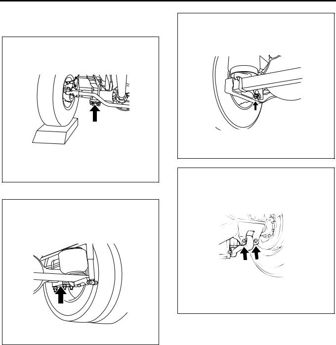
General Information 0A-19
NOTE:
Let the tire run over a piece of block, etc., and apply the jack.
FTS model(rear single-tire model)
MFU9Z0SH015401
FVR/FVM/FVZ/GVR models (with air suspension, except Europe)
MFU8Z0SH037501
FVR model (with air suspension, for Europe)
MFU8Z0SH077401
FVM/FVZ models (with leaf spring suspension)
MFW80ASH000301

0A-20 General Information
Caution for The Maintenance of Electrical Parts
Battery Cable
Disconnecting the battery cables
1.Turn all the switches "OFF".
2.Disconnect the battery ground cable (1).
3.Disconnect the battery plus cable (3).
4.Disconnect the battery cable (2).
CAUTION:
Make sure to disconnect the battery ground cable first. Disconnecting the plus cable first may cause a short circuit.
3
1
2
MFW70ASH000401
Connecting the battery cables
Connect the battery cables in the reverse order of the disconnection procedure.
CAUTION:
Clean the area surrounding the battery terminal, and apply a thin layer of grease to the terminal to prevent corrosion.
Connector Handling Requirements
Visual inspection
With the male and female connectors connected
•Gently pull the connector and check whether the connector becomes disconnected or partially disconnected, and that the lock is properly set.
If a problem is found, reconnect the connectors.
•Check that there is no damage to the connector
housing.
If a problem is found, perform replacement. With the male and female connectors disconnected
•Check that no foreign material or water has entered the inside of the connectors.
Remove any foreign material or water that has entered the connector using an air brush, etc. If the material cannot be removed, replace them.
•Check that no foreign material is stuck to the terminals, and there is no corrosion or deformation.
Remove any foreign material by cleaning with an air brush, or clean rag, etc. If the material cannot be removed by cleaning, or there is corrosion or deformation, replace them.
•Gently pull the wires to check that no terminals are missing from the connector and there is no breakage in the terminal area.
If a terminal is missing, reinsert it until it locks into place. If you find a disconnection, replace them.
•Insert the male connector into the same female connector, and check that there is no abnormality in the terminal contact pressure.
If you find an abnormality, replace them.
•For waterproof connectors, check that there is no damage or foreign material stuck to the seal parts (wire seal of wiring, O-ring or waterproofing seal of connector, etc.) or seal area of the connector housing.
Remove any foreign material by cleaning with an air brush, or clean rag, etc. If the material cannot be removed by cleaning, or there is damage, replace them.
CAUTION:
•Do not perform polishing that would remove the plating of the terminals, nor wash the inside of the connector. If there is dirt that requires washing, replace them.
•Be careful when attaching the seal areas of waterproof connectors, as some have specific positions and directions they must be attached. Also do not attach them in a twisted state.
Regarding vehicle washing
Even for electric parts that are installed outside the cab and are waterproofed, try to avoid exposing them directly to high pressure water when washing the vehicle (cover them with plastic sheets, etc.) as much as possible.
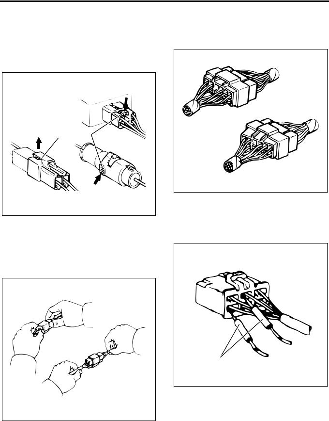
General Information 0A-21
Disconnecting the connector
Many connectors have a lock to ensure secure connections.
The two types of locks generally used are those that open by lifting the release area of the lock (1), and those that open by pressing the release area (2). Before disconnecting the connector, determine in advance which type of lock the connector is using.
12
LNW20ASH001201
When disconnecting the connector, first securely grasp the male side and female side of the connector. Release the lock, and carefully disconnect the connector.
Do not pull the harness when disconnecting the connector, as this may cause wires to come out or break.
OK
NO
LNW20ASH001301
Connecting the connector
Securely grasp the female side and male side of the connector, and align them correctly.
Firmly push them together until both sides click into place.
OK
NO
LNW20ASH001401
Connector circuit inspection requirements
Check the continuity of the connector using a circuit tester. Insert the probes (1) of the tester from the harness side of the connector, as indicated in the diagram.
OK
1
LNW20ASH001501

0A-22 General Information
Never insert the probes (1) from the connection closure area of the connector, as this will cause the connector terminals to break.
NO
1
LNW20ASH001601
Inspection requirements for waterproof connector circuit
For waterproof connectors, the probes of the tester cannot be inserted from the wiring side, due to the structure of the connectors.
Therefore, perform the continuity inspection as indicated in the diagram, by connecting a testing connector (1) prepared in advance to the connector (2) to test, and connect the probes (3) of the tester to the harness of the testing connector.
1
2
3
LNW20ASH001701
Disconnecting connector terminals —Built-in lock type
1.As indicated in the diagram, insert a thin screwdriver-shaped metal rod (1) from the connector closure area (5).
2.Push the lock (2) up in the direction of the arrow using the metal rod to release the lock. In that state, pull out the harness (3) together with the terminal (4).
1 |
2 |
|
5 |
4 |
3 |
|
|
|
|
|
LNW20ASH001801 |
—Terminal lock type
1.Insert a metal rod (1) from the connector closure area (5).
2.As indicated in the diagram, release the terminal lock (2) by pushing it to the harness side, pull out the harness (3) together with the terminal (4).
1
2
3
54
LNW20ASH001901
Connecting connector terminals
1.Check that the terminal lock (1) area is raised fully and can be locked.
2.Insert the terminal (3) from the harness (2) side of the connector, and push it in until the lock area clicks.

General Information 0A-23
3.Gently pull the harness and check whether the terminal is completely locked inside the connector.
1 |
2 |
3 |
LNW20ASH002001 |
Replacing the fuse
WARNING:
If a fuse melts down, make sure to replace it with a nondefective fuse of the same capacity, after identifying the cause of the melt down.
If you use a fuse with high capacity, the fuse will not perform its function when excess current flows. This may cause parts or wires, etc. to burn, and can result in a vehicle fire.
30A |
60A |
10 |
15 |
LNW20ASH002101
Handling Electronic Parts
Handle electronic parts with sufficient care, and do not damage the parts by dropping or throwing them.
LNW20ASH002201
Cable Harness
1.When installing electronic parts, take care to ensure the harness does not get stuck and do not forcibly push the harness in.
LNW20ASH002301
2.Make sure that all connections are clean and secure.

0A-24 General Information
3.When the harness will be contacting sharp edges or surfaces of other parts, protect the harness using a grommet or tube to prevent damage due to the contact.
NO
OK
LNW20ASH002401
4.When wiring the harness by diverting it around other parts, give the harness a sufficient amount of free length, and use a protective tube (2) and clip
(1) to ensure it does not contact surrounding parts.
|
NO |
1 |
2 |
|
|
OK |
|
|
LNW20ASH002501 |
5.For wiring between the engine and chassis, give the wiring sufficient free length to prevent wear and damage caused by vibrations.
NO
OK
LNW20ASH002601

General Information 0A-25
Regarding The Scan Tool
Trouble Diagnosis Using The Scan Tool
Regarding the scan tool (Tech2) / Tech2 24 volt adaptor 2 /CAN-di module
This tool is effective for diagnosing electrical failures in electronic control units and performing system checks. If you connect the Tech2 to the DLC installed in the vehicle, it performs communication with the control units of the vehicle, and enables various diagnoses and tests to be performed.
1 |
2 |
3 |
HCW35ALF001301 |
Legend
1. PCMCIA card (dedicated) 3. DLC cable
2. Tech2 (body)

0A-26 General Information
12
4
3
LNW7Z0SF000101
Legend |
|
|
|
1. |
Tech2 24V adaptor 2 (body) |
3. |
Tech2 connecting cable |
2. |
Signal change switch |
4. |
DLC connecting cable |
[Euro4 specification]
1
2
3
LNW7Z0SF000401
Legend
1. CAN-di module (body) 3. DLC connecting cable 2. Tech2 connecting cable
Features and cautions regarding the scan tool (Tech2) / Tech2 24 volt adaptor 2 / CAN-di module [Euro4 specification]
•The Tech2 has a 12 V power system. Do not directly use 24 V power. Do not directly supply power from the cigar lighter.
•Remove/install the PCMCIA card after turning the power off.
•The Tech2 has the capacity for two snapshots.
•As the PCMCIA card is sensitive to magnetism and static electricity, take care when handling it.
•The Tech2 is able to draw graphs of snapshots.
•To select a menu, press the selection key or choose a menu with a function key and press the ENTER key.
•You can return to the main menu at any time by pressing the EXIT key.
•To clear the diagnostic trouble codes (DTC), open the application menu and select "Clear DTC Information".
•The Tech2 adaptor 2 has a built-in DC to DC converter (that converts 24 V to 12 V).
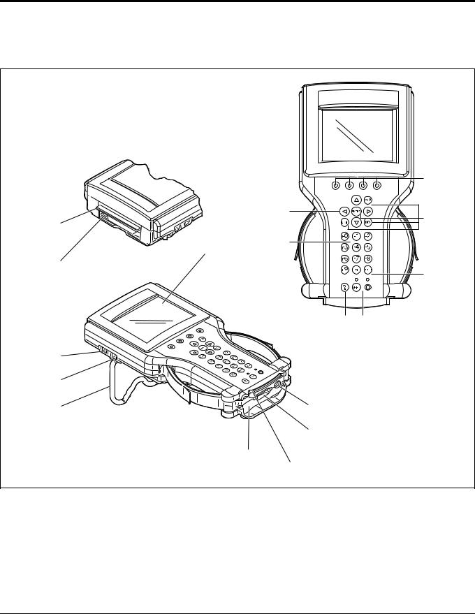
General Information 0A-27
•The Tech2 adaptor 2 has a selector for switching signals (the signals for each electronic control unit (ECU)).
•The CAN-di module has a built-in signal converter (that converts CAN serial data to keyword serial data)
Parts of the Tech2
|
|
1 |
|
2 |
|
|
|
3 |
13 |
|
|
|
4 |
|
|
8 |
|
14 |
|
|
|
|
3 |
|
5 |
6 |
15 |
|
|
16 |
|
|
7 |
12 |
|
|
11 |
|
|
9 |
|
|
10 |
|
|
|
HCW35ALF001401 |
Legend |
10. |
VCI module fastening bar |
|
1. |
Soft key |
||
2. |
Selection key (arrow key) |
11. |
DLC cable connecting connector |
3. |
Action keys (YES, NO, ENTER, EXIT) |
12. |
AC adaptor connector |
4. |
Function key (F0 – F9) |
13. |
PCMCIA card insertion opening (with cover) |
5. |
Help key (?) |
14. |
PCMCIA card release (removal) button |
6. |
Control key (PWR or SHIFT) |
15. |
Connector for external communication (RS-485 |
7. |
Wide stand |
|
port) |
8. |
Display (liquid crystal display) |
16. |
Connector for external communication (RS-232 |
9. |
Vehicle communication interface (VCI) Module |
|
port) |
1. Soft keys |
displayed on the screen. |
When operating the Tech2, the selection box is |
2. Selection key (arrow key) |
displayed on the top of the screen. The soft keys |
Selects menu items on the Tech2 screen, and |
correspond to that selection box. The soft keys |
switches the display. The highlighted area of the |
cannot be used unless the selection box is |
screen display indicates what is being selected. |
Loading...