


Diesel Injection Pump
SERVICE MANUAL
Common Rail System for ISUZU
4HK1 / 6HK1 Type Engine
OPERATION
February, 2004
00400056E
FORWARD
To meet the high pressurization requirements for the engine to deliver cleaner exhaust gas emissions, lower fuel consumption and reduced noise, advanced electronic control technology is being adopted in the fuel injection system. This manual covers the electronic control model Common Rail system with HP3/HP4 pump for the ISUZU 4HK1/6HK1 type engines which are used to ELF and GM 560 series respectively. Complex theories, special functions and components made by manufacturers other than DENSO are omitted from this manual.
This manual will help the reader develop an understanding of the basic construction, operation and system configuration of the DENSO manufactured components and brief diagnostic information.
TABLE OF CONTENTS
1. |
Product Application . . . . . . . . . . . . . . . . . . . . . . . . . . . . . . . . . . . . . . . . . . . . . . . . . . . . . . . . . . . . . . . . . . . . . . . . . . . . . . . . . . . . |
1 |
|
|
1-1. |
Application . . . . . . . . . . . . . . . . . . . . . . . . . . . . . . . . . . . . . . . . . . . . . . . . . . . . . . . . . . . . . . . . . . . . . . . . . . . . . . . . . . . . . . . |
1 |
|
1-2. System Components Parts Numbers . . . . . . . . . . . . . . . . . . . . . . . . . . . . . . . . . . . . . . . . . . . . . . . . . . . . . . . . . . . . . . . . . . |
1 |
|
2. |
Outline . . . . . . . . . . . . . . . . . . . . . . . . . . . . . . . . . . . . . . . . . . . . . . . . . . . . . . . . . . . . . . . . . . . . . . . . . . . . . . . . . . . . . . . . . . . . . . . |
2 |
|
|
2-1. |
Outline of System . . . . . . . . . . . . . . . . . . . . . . . . . . . . . . . . . . . . . . . . . . . . . . . . . . . . . . . . . . . . . . . . . . . . . . . . . . . . . . . . . . |
2 |
|
2-2. |
Outline of System . . . . . . . . . . . . . . . . . . . . . . . . . . . . . . . . . . . . . . . . . . . . . . . . . . . . . . . . . . . . . . . . . . . . . . . . . . . . . . . . . . |
4 |
|
2-3. Fuel System and Control System . . . . . . . . . . . . . . . . . . . . . . . . . . . . . . . . . . . . . . . . . . . . . . . . . . . . . . . . . . . . . . . . . . . . . |
5 |
|
3. |
Construction and Operation . . . . . . . . . . . . . . . . . . . . . . . . . . . . . . . . . . . . . . . . . . . . . . . . . . . . . . . . . . . . . . . . . . . . . . . . . . . . . |
6 |
|
|
3-1. |
Description of Main Components . . . . . . . . . . . . . . . . . . . . . . . . . . . . . . . . . . . . . . . . . . . . . . . . . . . . . . . . . . . . . . . . . . . . . |
6 |
|
3-2. Description of Control System Components . . . . . . . . . . . . . . . . . . . . . . . . . . . . . . . . . . . . . . . . . . . . . . . . . . . . . . . . . . |
22 |
|
|
3-3. Various Types of Control . . . . . . . . . . . . . . . . . . . . . . . . . . . . . . . . . . . . . . . . . . . . . . . . . . . . . . . . . . . . . . . . . . . . . . . . . . . |
24 |
|
|
3-4. |
Engine ECU . . . . . . . . . . . . . . . . . . . . . . . . . . . . . . . . . . . . . . . . . . . . . . . . . . . . . . . . . . . . . . . . . . . . . . . . . . . . . . . . . . . . . . |
31 |
1. |
|
Product Application |
|
|
|
|
|
|
|
|
|
|
|
1-1. |
Application |
|
|
|
|
|
|
|
|
|
|
||
|
|
|
|
|
|
|
|
|
|
|
|
|
|
|
|
Vehicle Name |
|
Engine Model |
|
Vehicle model |
|
Exhaust Volume |
|
Reference |
|||
|
|
|
|
|
|
|
|
|
|
|
|
|
|
|
|
|
|
|
|
|
|
|
|
|
|
|
|
|
ELF |
|
|
4HK1 |
|
N series |
|
5.2L |
|
|
Direct-Injection |
||
|
|
|
|
|
|
|
|
|
|
|
|
|
|
|
C560 Series |
|
|
6HK1 |
|
GM 560 |
|
7.8L |
|
|
Direct-Injection |
||
|
|
|
|
|
|
|
|
|
|
|
|
||
1-2. System Components Parts Numbers |
|
|
|
|
|
|
|
||||||
|
|
|
|
|
|
|
|
|
|
|
|
||
|
|
Parts Name |
|
DENSO Parts Number |
Car Manufacturer Parts |
|
|
Reference |
|||||
|
|
|
|
Number |
|
|
|||||||
|
|
|
|
|
|
|
|
|
|
|
|
||
|
|
|
|
|
|
|
|
|
|||||
|
|
|
|
|
|
|
|
|
|||||
|
Supply Pump |
|
294000-0260 |
|
|
8973288860 |
4HK1 |
|
|||||
|
|
|
|
|
|
|
|
|
|
|
|||
|
|
|
|
|
294050-0021 |
|
|
9876020491 |
6HK1 |
|
|||
|
|
|
|
|
|
|
|
|
|||||
|
Injector |
|
095000-5351 |
|
|
8976011561 |
6HK1 |
|
|||||
|
|
|
|
|
|
|
|
|
|
|
|
||
|
|
|
|
|
095000-5361 |
|
|
8976028031 |
|
|
|
||
|
|
|
|
|
|
|
|
|
|
|
|||
|
|
|
|
|
095000-5471 |
|
|
8973297031 |
4HK1 |
|
|||
|
|
|
|
|
|
|
|
|
|||||
|
Rail |
|
095440-0351 |
|
|
8973060632 |
4HK1 |
|
|||||
|
|
|
|
|
|
|
|
|
|
|
|||
|
|
|
|
|
095440-0470 |
|
|
8973230190 |
6HK1 |
|
|||
|
|
|
|
|
|
|
|
|
|||||
|
Engine ECU |
|
275800-2801 |
|
|
8151794773 |
6HK1 |
|
|||||
|
|
|
|
|
|
|
|
|
|
|
|||
|
|
|
|
|
275800-2812 |
|
|
8973750190 |
4HK1 |
|
|||
|
|
|
|
|
|
|
|
|
|
|
|
||
|
|
|
|
|
275800-2822 |
|
|
8973750200 |
|
|
|
||
|
|
|
|
|
|
|
|
|
|
|
|
|
|
-1-

2.Outline
2-1. Outline of System
The common rail system was developed primarily to cope with exhaust gas regulations for diesel engines, and aimed for
1. further improved fuel economy; 2. noise reduction; and 3. high power output.
A.System Characteristics
The common rail system uses a type of accumulation chamber called a rail to store pressurized fuel, and injectors that contain electronically controlled solenoid valves to spray the pressurized fuel into the cylinders.
Because the engine ECU controls the injection system (including the injection pressure, injection rate, and injection timing), the injection system is unaffected by the engine speed or load.
This ensures a stable injection pressure at all times, particularly in the low engine speed range, and dramatically decreases the amount of black smoke ordinarily emitted by a diesel engine during start-up and acceleration.
As a result, exhaust gas emissions are cleaner and reduced, and higher power output is achieved.
a.Injection Pressure Control
Enables high-pressure injection even at low engine speeds.
Optimizes control to minimize particulate matter and NOx emissions.
b.Injection Timing Control
Enables finely tuned optimized control in accordance with driving conditions.
c.Injection Rate Control
Pilot injection control sprays a small amount of fuel before the main injection.
|
|
|
||||||
|
|
|
|
|
||||
|
|
|
|
|
|
|
||
|
|
|
|
|
|
|
|
|
|
|
|
|
|
|
|
|
|
|
|
|
|
|
|
|
||
|
|
|
|
|
|
|||
|
|
|
|
|
|
|||
|
|
|
|
|
||||
|
|
|
|
|||||
|
|
|
|
|
||||
|
|
|
||||||
|
|
|
|
|||||
|
|
|
|
|
|
|
|
|
|
|
|
|
|
|
|
|
|
d.EGR (Exhaust Gas Recirculation) Control
By recirculating the exhaust gas into the intake side of the engine, the combustion temperature is reduced and NOx is decreased.
-2-
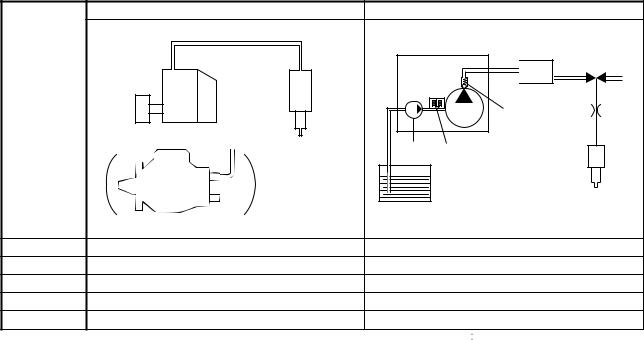
B. Comparison to the Conventional System
|
|
|
|
|
|
|
|
|
|
|
|
|
|
|
|
|
|
|
|
|
|
||
|
|
|
|
||
|
|
|
|
|
|
|
|
|
|
||
|
|
|
|
||
|
|
|
|
|
|
|
|
|
|
|
|
|
|
|
|
|
|
|
|
|
|
|
|
|
|
|
|
|
|
|
|
|
|
|
|
|
|
|
|
|
|
|
|
|
|
|
|
|
|
|
|
|
|
|
|
|
|
|
|
|
|
|
|
|
|
|
|
|
|
|
|
|
|
|
|
||
|
|
|
|
|
|
-3-
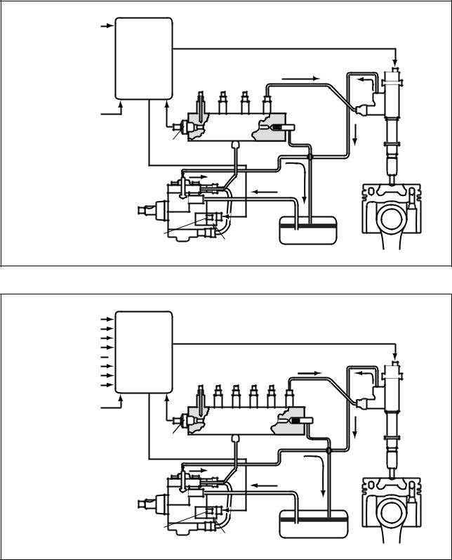
2-2. Outline of System
A. Composition
The common rail system consists primarily of a supply pump, rail, injectors, and engine ECU.
a.4HK1


|
|
|
|
|
|
|
|
|
|||
|
|
||
|
|
|
|
|
|
|
|
|
|
|
|
|
|
|
|
|||
|
|
|
|
|
|
|
b.6HK1

|
|
|
|
||
|
||
|
||
|
|
|
|
|
|
|
|
|
|
|
|
|
|
|||
|
|
|
|
|
|
|
-4-
B. Operation
a.Supply pump (HP3/HP4)
The supply pump draws fuel from the fuel tank, and pumps the high pressure fuel to the rail. The quantity of fuel discharged from the supply pump controls the pressure in the rail. The SCV (Suction Control Valve) in the supply pump effects this control in accordance with the command received from the ECU.
b.Rail
The rail is mounted between the supply pump and the injector, and stores the high pressure fuel.
c.Injector (G2 type)
This injector replaces the conventional injection nozzle, and achieves optimal injection by effecting control in accordance with signals from the ECU. Signals from the ECU determine the length of time and the timing in which current is applied to the injector.
This in turn, determines the quantity, rate and timing of the fuel that is injected from the injector.
d.Engine ECU
The engine ECU calculates data received from the sensors to comprehensively control the injection quantity, timing and pressure, as well as the EGR (exhaust gas recirculation).
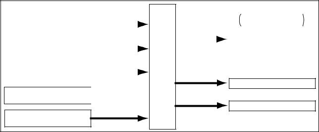
2-3. Fuel System and Control System
A. Fuel System
This system comprises the route through which diesel fuel flows from the fuel tank to the supply pump, via the rail, and is injected through the injector, as well as the route through which the fuel returns to the tank via the overflow pipe.
B. Control System
In this system, the engine ECU controls the fuel injection system in accordance with the signals received from various sensors. The components of this system can be broadly divided into the following three types: (a.) Sensors; (b.) Engine ECU; and (c.) Actuators.
a.Sensors
Detect the engine and driving conditions, and convert them into electrical signals.
b.Engine ECU
Performs calculations based on the electrical signals received from the sensors, and sends them to the actuators in order to achieve optimal conditions.
c.Actuators
Operate in accordance with electrical signals received from the ECU. Injection system control is undertaken by electronically controlling the actuators. The injection quantity and timing are determined by controlling the length of time and the timing in which the current is applied to the TWV (Two-Way Valve) in the injector. The injection pressure is determined by controlling the SCV (Suction Control Valve) in the supply pump.
|
|
|
|
|
||||
|
|
|
|
|
|
|
||
|
|
|||||||
|
|
|
|
|
|
|||
|
|
|
|
|
|
|
|
|
|
|
|
|
|||||
|
|
|
|
|
|
|
|
|
|
|
|
|
|
|
|
|
|
|
|
|
|
|
|
|
|
|
|
|
|
|
|
|
|
||
|
|
|
|
|
||||
|
|
|
|
|
|
|
|
|
|
||||||||
|
||||||||
|
|
|
|
|
|
|
|
|
|
|
|
|
|
||||
|
|
|
|
|||||
|
|
|
||||||
|
|
|
|
|
|
|||
|
|
|
|
|
||||
|
|
|
|
|
|
|
|
|

-5-

3.Construction and Operation
3-1. Description of Main Components
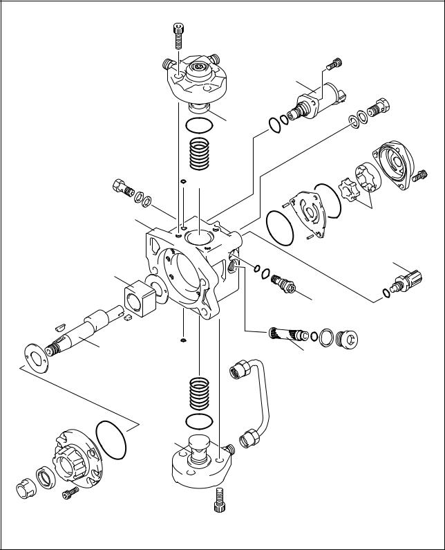
A. Supply Pump (HP3, HP4)
a.Outline
The supply pump consists primarily of the pump body (cam shaft, ring cam, and plungers), SCV (Suction Control Valve), fuel temperature sensor, and feed pump.
The two plungers for HP3 or the three plungers for HP4 are positioned vertically on the outer ring cam for compactness.
The engine drives the supply pump at a ratio of 1:1. The supply pump has a built-in feed pump (trochoid type), and draws the fuel from the fuel tank, sending it to the plunger chamber.
-6-

The internal camshaft drives the two plungers, and they pressurize the fuel sent to the plunger chamber and send it to the rail. The quantity of fuel supplied to the rail is controlled by the SCV, using signals from the engine ECU. The SCV is a normally opened type (the intake valve opens during de-energization).
|
|
|
|
|
|
|
|
|
|
||
|
|||||
|
|
|
|
||
|
|
|
|
||
|
|
|
|
||
|
|
|
|
||
|
|
|
|
|
|
|
|
|
|
|
|
|
|
|
|
||
|
|
|
|||
|
|
|
|
|
|
|
|
|
|
|
|
|
|
|
|
||
|
|
|
|
|
|
|
|
|
|
||
|
|
|
|
|
|
|
|
|
|
|
|
|
|
|
|
|
|
-7-
|
Development: HP3 |
|
|
|
|
|
|
|
|
|
|
|
|
|
|
|
|
|
|
|
|
|
|
|
|
|
|
|
|
|
|
|
|
|
|
|
|
|
|
|
|
|
|
-8- |

|
Development: HP4 |
|
|
|
|
|
|
|
|
|
|
|
|
|
|
|
|
|
|
|
|
|
|
|
|
|
|
|
|
|
|
|
|
|
|
|
|
|
|
|
|
-9-
b.Supply Pump Internal Fuel Flow
The fuel that is drawn from the fuel tank passes through the route in the supply pump as illustrated, and is fed into the rail.
|
|
|
|
|
|
|
|
|
|
|
|
|
|
|
|
|
|
|
|
|
|
|
|
|
|
|
|
|
|
|
|
|
|
|
|
|
|
|
|
|
|
||
|
|
|
|
|
|
|
|
|
|
|
|
|
|
|
|
|
|
|
|
|
|
|
|
|
|
|
|
|
|
|
|
|
|
|
|
|
|
|
|
||||
|
|
|
|
|
|
|
|
|
|
|
|
|
|
||||||||
|
|
|
|
|
|
|
|
|
|
|
|
|
|
|
|
|
|
|
|
|
|
|
|
|
|
|
|
|
|
|
|
|
|
|
|
||||||||
|
|
|
|
|
|
|
|
|
|
|
|
|
|
|
|
|
|
|
|||
|
|
|
|
|
|
|
|
|
|
|
|
|
|
|
|||||||
|
|
|
|
|
|
|
|
|
|
|
|
|
|
|
|
|
|
|
|||
|
|
|
|
|
|
|
|
|
|
|
|
|
|
|
|
|
|
|
|
|
|
|
|
|
|
|
|
|
|
|
|
|
|
|
|
|
|
|
|
|
|
|
|
|
|
|
|
|
|
|
|
|
|
|
|
|
|
|
|
|
|
||||
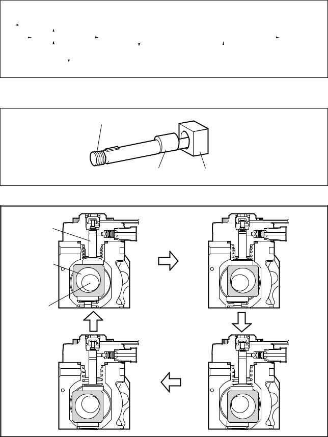
c.Construction of Supply Pump (in case of HP3 pump)
The eccentric cam is attached to the cam shaft. The eccentric cam is connected to the ring cam.
As the cam shaft rotates, the eccentric cam rotates eccentrically, and the ring cam moves up and down while rotating.

-10-

The plunger and the suction valve are attached to the ring cam. The feed pump is connected to the rear of the cam shaft.
-11-
d.Operation of the Supply Pump
As shown in the illustration below (in case of HP3 pump), the rotation of the eccentric cam causes the ring cam to push Plunger A upwards. Due to the spring force, Plunger B is pulled in the opposite direction to Plunger A.
As a result, Plunger B draws in fuel, while Plunger A pumps it to the rail. In the case of the 4-cylinder engine used with the HP3 pump, each plunger pumps fuel in a reciprocal movement during the 360 cam rotation.
Conversely, in the case of the 6-cylinder engine used with the HP4 pump, 3 plungers pump fuel in a reciprocal movement for each one rotation of the cam.
|
|
|
|
|
|
|
|
|
|
|
|
|
|
|
|
|
|
|
|
|
|
|
|
|
|
|
|
|
|
|
|
|
|
|
|
|
|
|
|
|
|
|
|
|
|
|
|
|
|
|
|
|
|
|
|
|
|
|
|
|
|
|
|
|
|
|
|
|
|
|
|
|
|
|
|
|
|
|
|
|
|
|
|
|
|
|
|
|
|
|
|
|
|
|
|
|
|
|
|
|
|
|
|
|
|
|
|
|
|
|
|
|
|
|
|
|
|
|
|
|
|
|
|
|
|
|
|
|
|
|
|
|
|
|
|
|
|
|
|
|
|
|
|
|
|
|
|
|
|
|
|
|
|
|
|
|
|
|
|
|
|
|
|
|
|
|
|
|
|
|
|
|
|
|
|
|
|
|
|
|
|
|
|
|
|
|
|
|
|
|
|
|
|
|
|
|
|
|
|
|
|
|
|
|
|
|
|
||||||||||||||||||||||||
|
|
|
|
||||||||||||||||||||||||
< NOTE >
There are 3 plungers for the HP4.
-12-

B. Description of Supply Pump Components
a.Feed Pump
The trochoid type feed pump, which is integrated in the supply pump, draws fuel from the fuel tank and feeds it to the two plungers via the fuel filter and the SCV (Suction Control Valve).
The feed pump is driven by the drive shaft. With the rotation of the inner rotor, the feed pump draws fuel from its suction port and pumps it out through the discharge port.
This is done in accordance with the space that increases and decreases with the movement of the outer and inner rotors.
|
|
|
|
|
|
||
|
|
||
|
|
|
|
|
|
|
|
|
|
|
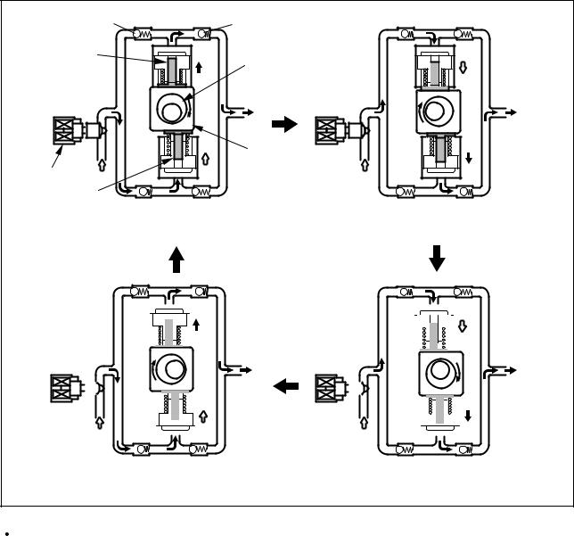
b.SCV: Suction Control Valve (Normally open type)
A linear solenoid type valve has been adopted. The ECU controls the duty ratio (the duration in which current is applied to the SCV), in order to control the quantity of fuel that is supplied to the high-pressure plunger.
Because only the quantity of fuel that is required for achieving the target rail pressure is drawn in, the actuating load of the supply pump decreases.
When current flows to the SCV, variable electromotive force is created in accordance with the duty ratio, moving the armature to the left side. The armature moves the cylinder to the left side, changing the opening of the fuel passage and thus regulating the fuel quantity.
With the SCV OFF, the return spring contracts, completely opening the fuel passage and supplying fuel to the plungers. (Full quantity intake and full quantity discharge)
When the SCV is ON, the force of the return spring moves the cylinder to the right, closing the fuel passage (normally opened).
By turning the SCV ON/OFF, fuel is supplied in an amount corresponding to the actuation duty ratio, and fuel is discharged by the plungers.
|
|
(1)In case of short time ON duty
-13-
 Loading...