


 Loading...
Body Builders Guide
I
Body Builders Guide
General Motors Isuzu Commercial Truck, LLC (GMICT) and American Isuzu Motors Inc.
Is striving to provide you with the most upto - date and accurate information possible . If you have any suggestion to improve the Body Builder's Guide, please call GMICT Application Engineering. In the West Coast call 1 - 562 - 229 - 5314 and in the East Coast call 1-404-257-3013
Notice of Rights
All rights reserved. No part of this book may be reproduced or transmitted in any form or by any means, electronic, mechanical, recording or otherwise, without the prior written permission.
Notice of Liability
All specifications contained in this Body Builders Guide are based on the latest product information available at the time of publication. The manufacturer reserves the right to discontinue or change at anytime without prior notice, any parts, material, colors, special equipment, specifications, designs and models.
Made and printed in the USA.
II
Contents
Introduction |
|
FMVSS |
|
EPA Requirements |
|
|
Weight Distribution |
Installation of Body & Special Equipment |
Glossary of Dimensions |
Clearances |
Weight Distribution Formulas |
Body Installations |
Recommended Weight Distribution |
Prohibited Attachment Areas |
Trailer Weight |
Subframe Mounting |
Performance Calculations |
Crew Cab Body/Frame Requirements |
Highway Limits |
Modification of the Frame |
Federal Bridge Formula Table |
Fluid Lines |
|
Electrical Wiring & Harnessing |
Commodity & Material Weights |
Maximum Allowable Current |
Approximate Weight of Commodites & Materials |
Exhaust System |
|
Fuel System |
Vehicle Specifications Index |
Rear Lighting |
NPR, NPR HD/W3500 W4500 Gas |
Servicability |
NPR, NPR HD/W3500 W4500 Diesel |
Wheelbase Alteration |
NQR/W5500 Diesel |
Hydraulic Brake System |
NPR, NPR HD NQR/W4500 W500 Crew Cab Diesel |
|
FRR/WT |
Body Application Summary Chart |
* FSR, FTR & FVR |
NPR, NPR HD/W3500 W4500 Gas |
NPR, NPR HD/W3500 W4500 Gas Cab Chssis Electrical |
NPR, NPR HD/W3500 W4500 Diesel |
NPR, NPR HD NQR/W3500 W4500 Diesel Cab Chssis Electrical |
NQR/W5500 Diesel |
NPR HD NQR/W4500 W500 Crew Cab Electrical |
NPR HD, NQR/W4500 W500 Crew Cab Diesel |
* FRR, FSR, FTR & FVR Cab Chassis Electrical |
FRR/WT |
|
|
*Note: 2002 FSR, FTR and FVR |
Mechanical & Cab Specifications |
|
Engine Horsepower & Torque Chart |
|
GVW/GCW Ratings |
|
Rear Frame Height Chart |
|
Clutch Engagement Torque |
|
Paint Code Chart |
|
* N/W Series Towing Procedure |
|
FRR/WT Series Towing Procedure |
|
FSR, FTR & FVR Series Towing Procedure |
|
Weight Distribution Concepts |
|
Weight Restriction |
|
Gross Axle Weight Rating |
|
Weighing the Vehicle |
|
Tire Inflation |
|
Center of Gravity |
|
III
IV
Introduction
This guide has been provided as an aid to final stage manufacturers in determining conformity to the applicable Emission Control and Federal Motor Vehicle Safety Standards. Final stage manufacturers should maintain current knowledge of all Emission Regulations and Federal Motor Vehicle Safety Standards and be aware of their specific responsibility in regards to each standard.
Any manufacturer making material alterations to this incomplete vehicle during the process of manufacturing the completed vehicle should be constantly alert to all effects, direct or indirect, on other components, assemblies or systems caused by such alterations. No alterations should be made to the incomplete vehicle that directly or indirectly results in any either component, assembly or system being in nonconformance with applicable Emission Regulations or Federal Motor Vehicle Safety Standards.
General Motors Isuzu Commercial Truck, LLC (GMICT) and American Isuzu Motors Inc. will honor its warranty commitment (for the cab-chassis only), to the ultimate consumer, provided: (1) the final stage manufacturer has not made any alterations or modifications which do not conform to any applicable laws, regulations or standards, or adversely affect the operation of the cab-chassis; and (2) the final stage manufacturer complied with the instructions contained in this guide with respect to the completion of the vehicle. Otherwise, the warranty becomes the responsibility of the final stage manufacturer.
The final stage manufacturer is solely responsible for the final certification of the vehicle and for compliance with Emission Control and Federal Motor Vehicle Safety Standards. The information contained in this guide has been provided for the final stage manufacturer’s information and guidance.
This guide contains information pertaining to the NPR/W Gas, NPR/W Diesel, NQR/W Diesel, NPR HD/NQR/W Diesel Crew Cab and FRR/WT Series Chassis Cab and Janesville assembled FSR, FTR and FVR Chassis Cab.
Following is a list of Federal Motor Vehicle Safety Standards applicable to those vehicles with a GVWR greater than 10,000 lbs. Please refer to the following chart.
V
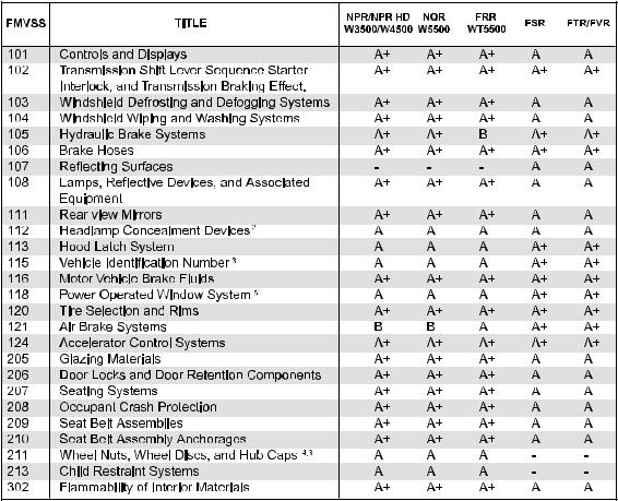
FMVSS Chart
NOTE: This chart is only a guide, for complete information please refer to "Document for Incomplete Vehicle” provided with each chassis.
Chart Legend:
AIncomplete vehicle; when completed will conform providing no alterations have been made affecting items covered by FMVSS regulations and "Document for Incomplete Vehicle.
BIncomplete vehicle; when completed by the final manufacturer will conform providing it is completed in compliance with FMVSS regulations and "Document for Incomplete Vehicle."
+Meets Canadian Motor Vehicle Safety Standards bearing same FMVSS number.
3Canadian MVSS only.
4Not applicable to truck or bus.
5Not applicable to trucks with a GVWR greater than 10,000 LBS.
VI
EPA Requirements
NPR/W Gas, NPR/W Diesel, NQR/W Diesel, NPR HD/NQR/W Diesel Crew Cab and FRR/WT Series Chassis Cab
To assure that U.S.A. and Canada Emission Requirements are met, this Incomplete Vehicle must be completed in strict accordance with all instructions contained in this document, especially the following instructions which relate to:
A.Exhaust emission related components
B.Noise emission related components
C. Labels
[A]EXHAUST EMISSION RELATED COMPONENTS
Compliance of this vehicle with EPA, California and Canada Requirements will be maintained providing no alterations are made to the components or systems identified below:
1) |
DIESEL VEHICLES |
2) |
GASOLINE VEHICLES |
|
Injection Pump |
|
Vehicle Control Module (VCM) |
|
Injector and High Pressure Lines |
|
Fuel Management System |
|
Turbocharger |
|
Air Induction System |
|
Charge Air Cooler and Charge |
|
Ignition System |
|
Air Cooler Hoses |
|
Catalytic Converter System |
|
Engine Control Module (ECM) |
|
Positive Crankcase Ventilation System |
|
Engine Speed Sensor |
|
Exhaust Gas Recirculation System |
|
Engine Coolant Temperature Sensor |
|
Evaporative Emission Control System |
|
Intake Manifold |
|
Miscellaneous Items Used in Above Systems |
|
Catalytic converter and its location |
|
|
|
Variable swirl system |
|
|
|
Exhaust Gas Recirculation System |
|
|
ADDITIONAL CANADA MOTOR VEHICLE SAFETY STANDARD
CMVSS NO. 1101-EMISSION DEVICE
CMVSS NO. 1102-CRANKCASE EMISSION (GASOLINE ENGINE ONLY)
CMVSS NO. 1103-EXHAUST EMISSIONS
CMVSS NO. 1104-OPACITY (DIESEL ENGINE ONLY)
CMVSS NO. 1105EVAPORATIVE EMISSION (GASOLINE ENGINE ONLY)
[B]NOISE
Compliance of this vehicle with EPA and Canada requirements will be maintained providing no alterations are made to the components or systems.
CMVSS NO. 1106-NOISE
This incomplete vehicle, when completed, will conform to the above standards except CMVSS-1106 providing no alterations are made which effect the function, physical or mechanical properties, environment, locations or vital spatial clearances of the components identified below:
* Engine assembly
Exhaust emission control system P.C.V. system (if equipped)
*Intake system
*Exhaust system
Fuel system (if equipped)
*Transmission assembly
*Axle
*Tires
*Fan and drive
Diesel fuel injection controls (if equipped) Turbocharger and associated controls (if equipped)
* Catalytic converter and its location Variable swirl system (if equipped)
VII
Conformity with CMVSS 1106 is not determined solely by the design of the incomplete vehicle. When completed, it should conform to CMVSS 1106 providing no alterations are made to the noise attenuation components identified thus * in the above list.
[C]LABELS
The Emission control related information labels which are permanently affixed are required by government regulation and must not be obstructed from view or defaced so as to impair its visibility or legibility.
PART 3 : Radio Noise
CANADIAN RADIO INTERFERENCE REGULATIONS
[A] The following statement is applicable to NPR/W Series Chassis-Cab (Gasoline Engine Only).
This incomplete Vehicle, when completed, will conform to the above regulations providing no alterations or substitutions are made which affect any parts or components identified below:
A.Distributor
B.Ignition Wires
C.Spark Plug Wires
FSR, FTR & FVR
U.S. ENVIRONMENTAL PROTECTION AGENCY AND STATE OF CALIFORNIA EMISSION REQUIREMENTS
To assure that EPA and California Emission Certificate Requirements are met, this incomplete vehicle must be completed in strict accordance with all instructions contained in this document, especially the following instructions which relate to:
A.Exhaust emission related components
B.Labels
[D]EXHAUST EMISSION RELATED COMPONENTS
Compliance of this vehicle with EPA and California Certification Requirements will be maintained providing no alterations are made to the components or systems identified below:
1.DIESEL VEHICLES
Injection Pump
Injector and High Pressure Lines Turbocharger
Charge Air Cooler and Charge Air Cooler Hoses Engine Control Module (ECM)
Engine Speed Sensor
Engine Coolant Temperature Sensor (6HE1-TC only) Intake Manifold
Catalytic converter and its location (6HE1-TC only) Air cylinder for variable swirl system (6HE1-TCS only)
[E]LABELS
The Emission control related information labels which are permanently affixed are required by government regulation and must not be obstructed from view or defaced so as to impair its visibility or legibility.
VIII
CANADIAN MOTOR VEHICLE SAFETY STANDARDS
CMVSS NO. 1101-EMISSION DEVICE
CMVSS NO. 1103-EXHAUST EMISSIONS
CMVSS NO. 1104-OPACITY
CMVSS NO. 1106-NOISE
This incomplete vehicle, when completed, will conform to the above standards except CMVSS 1106 providing no alterations are made which affect the function, physical or mechanical properties, environment, locations or vital spatial clearances of the components identified below:
Engine assembly*
Exhaust emission control system
P.C.V. system
Intake system*
Exhaust system*
Fuel system
Transmission assembly*
Axle*
Tires*
Fan and drive*
Diesel fuel injection controls
Turbocharger and associated controls
Catalytic converter and its location (6HE1-TC only) *
Air cylinder for variable swirl system (6HE1TCS only)
Conformity with CMVSS 1106 is not determined solely by the design of the incomplete vehicle. When completed, it should conform to CMVSS 1106 providing no alterations are made to the noise attenuation components identified thus * in the above list.
Compliance of this vehicle with EPA and California Certification Requirements will be maintained providing no alterations are made to the components or systems identified below:
Air Inlet System
Diesel Fuel Injection Controls
Engine Assembly with all Components of Exhaust Emission Control System
Exhaust System
Fuel System
Turbocharger and Associated Controls
IX
Installation of Body & Special Equipment
Installation of Body
&
Special Equipment
April 2002 |
1 |

Installation of Body & Special Equipment
Clearances
Engine
At least 1.6 inch clearance should be maintained around the engine. No obstacles should be added in front of the radiator or intercooler.
1.6 Inch |
|
Clearance |
|
1.6 Inch |
1.6 Inch |
Clearance |
|
|
Clearance |
|
Engine |
Transmission
The transmission is removed from the rear. Enough clearance must be provided to allow rearward movement of the transmission assembly. Clearance should be sufficient to allow 5 to 6 inches unrestricted movement of the transmission assembly. In addition, provide at least 2 inches clearance around the control lever on the side of the transmission to allow free movement without any binding.
|
5-6 Inch |
Engine |
Clearance |
|
|
|
Transmission |
At least 6 inches clearance should be maintained above the transmission to allow easy removal of the upper cover for manual transmissions. At least 2 inches clearance should be maintained above the automatic transmission to allow for transmission removal.
5.9
(150) Inches or More M/T
2.0
(58) Inches or More A/T
Transmission
2 |
April 2002 |
Installation of Body & Special Equipment
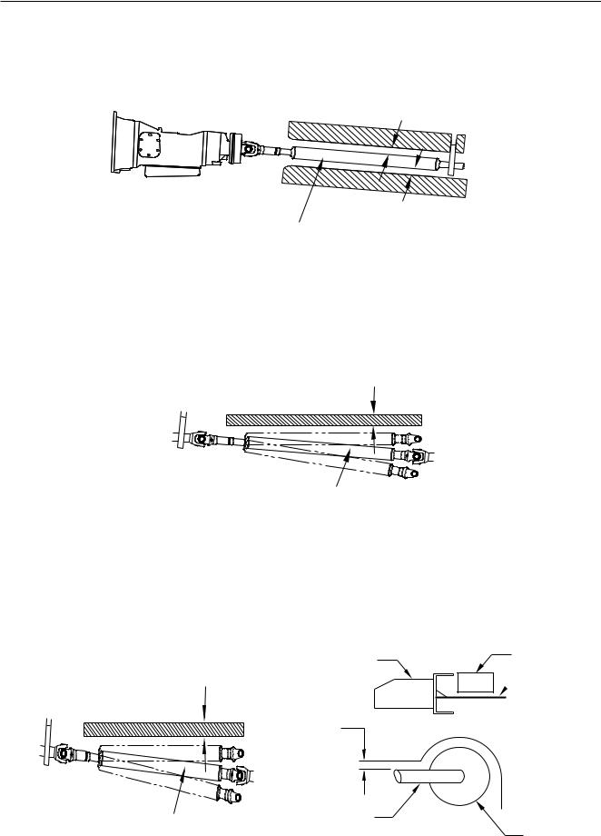
Front and Center Propeller Shafts
At least 1.25 inch clearance should be maintained around front and center propeller shafts.
1.25 Inches or more
1.25 Inches or more
Front Propellar Shaft
Rear Propeller Shaft
With the rear springs at maximum deflection, at least 1.25 inch clearance should be provided over the rear propeller shaft.
1.25 Inches or more
Front Propellar Shaft
Exhaust System
If flammable materials such as wood are used in the body, provide at least 3.9 inches clearance between the body and any parts of the exhaust pipe, muffler and catalytic converter. If it is impossible to maintain this minimum clearance, use a heat shield. Also use a heat shield if an oil pump or line is located above the exhaust pipe, muffler or catalytic converter.
1.25 Inches or more
Tool Box |
Oil Pump |
|
 Heat Shield
3.9 Inch
Clerance
Front Propellar Shaft
Exhaust Pipe
Muffler
April 2002 |
3 |
Installation of Body & Special Equipment
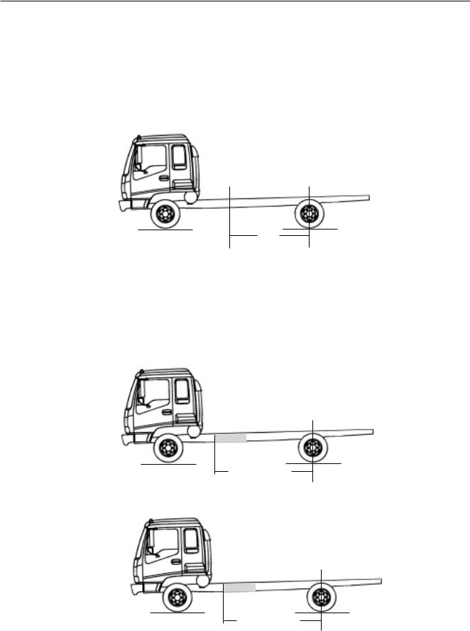
Rear Wheel and Axle
The design and installation of the body should allow sufficient clearance for full vertical movement of the rear wheels and axle when the vehicle travels over rough or unlevel surfaces.
Rear of Body
*NOTE: For recomended clearances please refer to the Rear Axle Chart in each models respective section.
Rear Wheels
Over High Spot
Normal Rear
Axle Center Line
Rear Wheels
Over Obstacle
Other Clearances
Transmission control cable may be broken if it is bent by or interferes with the body and its fixtures. To prevent this, 1 inch minimum clearance should be provided. When cable is detached for body mounting, be sure not to bend the cable.
Accessibility to the grease nipple on the rear spring bracket/shackle should be provided so that serviceability with a grease gun is not hampered.
|
MINIMUM |
|
PARTS |
CLEARANCE |
LOCATION |
|
|
|
Brake Hose |
6.7 in. |
Axle side |
|
1.6 in. |
Frame side |
|
|
|
Parking Brake Cable |
1.2 in. |
-------- |
|
|
|
Fuel Hose |
1.6 in. |
-------- |
|
|
|
Shock Absorber |
2.4 in. |
Axle Side |
|
1.2 in. |
Frame Side |
4 |
April 2002 |
Installation of Body & Special Equipment
Body Installation
Chassis
To maintain the performance of the truck chassis, either a side member or subframe should always be used for body mounting. Body mounting with low rigidity will often adversely affect riding comfort.
Special Equipment on the Chassis
When installing special equipment on the chassis, extra consideration must be given to the weight and construction of the equipment to assure proper distribution of the load. Localization of the load should be prevented. All special equipment should be properly secured into position. We recommend the use of subframe members when installing special equipment.
Subframe Design and Mounting
The subframe assembly should be mounted as close to the cab as possible. It should be contoured to match the shape and dimensions of the chassis frame as closely as possible.
Rear End of the Cab
April 2002 |
5 |
Installation of Body & Special Equipment
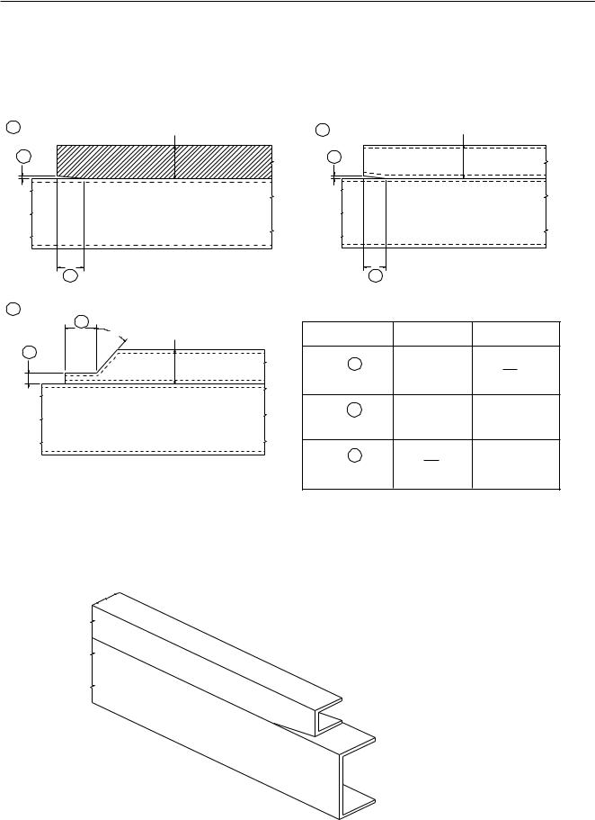
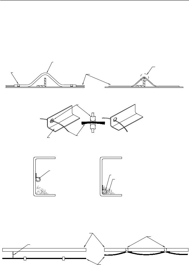
Subframe Contour
Contouring of the front end of the subframe members as shown in the three illustrations below will prevent stresses from being concentrated on certain areas of the chassis frame.
1 |
H |
2 |
H |
|
Wooden subframe |
Steel subframe |
|
|
|
A A
B |
|
B |
|
|
3 |
|
|
|
|
B |
|
Drawing |
A |
B |
45o |
H |
|||
A |
|
Steel subframe |
|
|
|
|
|
|
|
|
|
1 |
0.2 in. |
H |
|
|
|
|
2 ~ H |
|
|
2 |
0.2 in. |
H or more |
|
|
3 |
H |
H or more |
|
|
|
3 |
|
When using a steel subframe, do not close the end of the subframe.
Steel subframe
Chassis frame
6 |
April 2002 |
Installation of Body & Special Equipment
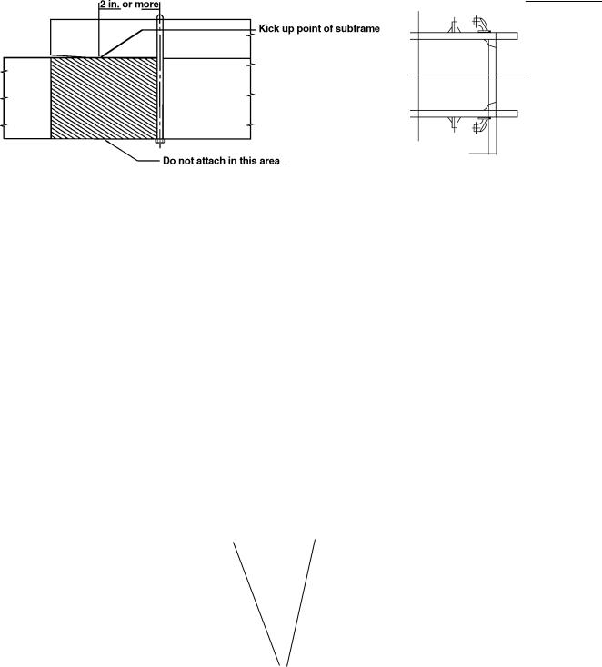
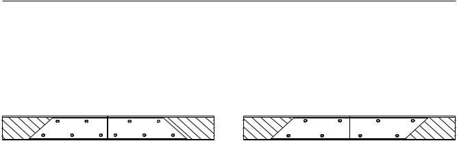
Prohibited Attachment Areas
Do not attach the subframe with a bolt on bracket to the chassis frame at the points indicated by shading in the following illustrations.
1.At the front end of the subframe. The attaching bolt or bracket must be at least 2 inches behind the kick up point of the subframe.
2. Within 8 inches of bends in the chassis frame or the attachment points of any cross members.
8 in. 8 in |
8 in. 8 in |
3.3 |
2.9 |
6.1 |
3.1 |
2.8 |
3.1 |
Do not attach in these areas.
April 2002 |
7 |

Installation of Body & Special Equipment
Subframe Mounting
Bracket Installation
Mounting brackets should be clamped to the chassis frame using bolts. For proper positions in which to install the bolts, refer to the preceding section and the section “Modifications to the Chassis Frame.”
Bolster
Subframe member |
Bracket |
Cushioning material
Cushioning material
Chassis frame
Chassis frame
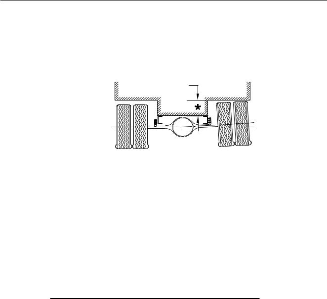
U-bolt Installation
When U-bolts are used to retain the subframe, reinforcement blocks must be installed in the frame members. This will prevent distortion of the frame flange as they are tightened. The drawing indicates the correct placement of reinforcement blocks. If you use wood blocks, be sure that there is sufficient clearance between them and any parts of the exhaust system.
If any fluid lines or electric cables are located near the reinforcement blocks, you must provide at least 0.4 inch clearance between rigid or stationary portions, and at least 1.6 inch between moveable or flexible portions of the lines.
Reinforcement block
(Reinforcement blocks should be mounted securely in installed position)
For the installation positions of the U-bolts, refer to “Prohibited Attachment Areas.”
8 |
April 2002 |
Installation of Body & Special Equipment
Crew Cab Body/Frame Requirement
The Crew Cab NPR HD/W4500 and NQR/W5500 will be available in two wheelbases, 150 and 176 inches. Effective CA will be 84.7 and 110.7 inches. On this model chassis General Motors Isuzu Commercial Truck, LLC (GMICT) and American Isuzu Motors Inc. will require that the body installed on the chassis have an understructure manufactured with any of the following structural steel "C" channels:
4"x1-5/8", 7.25 lbs/ft = ok 5"x1-3/4", 6.7 or 9.0 lbs/ft = ok 6"x2", 8.2, 10.5 or 13.0 lbs/ft = ok
Modification of the Frame
Modification of chassis frame should be kept to an absolute minimum. Modification work should be performed according the instructions in the following paragraphs.
When modification is complete, chassis frame members should be carefully inspected to eliminate the possibility of any safety-related defects.
NOTE: PLEASE REFER TO NOTES ON CHASSIS FRAME MODIFICATION WITH ANTILOCK BRAKES ON PAGES 27 AND 28
Working on Chassis Frame
The chassis frame is designed and built with consideration for proper load distribution. Sufficient physical strength is provided when the load is evenly distributed. Installation of special equipment on the chassis frame can cause variations in load distribution. If even distribution of load is not kept in mind when the equipment is installed, localization of stresses on specific areas of the frame could cause cracking of the chassis frame members or other problems, even if the total weight of the equipment is within the design limit.
The chassis frame is designed as an integral unit. Therefore, we do not recommend cutting the chassis frame under any circumstances.
IMPORTANT NOTE
Drilling and Welding
For vehicles equipped with electronic or hydra-matic transmissions electric arc welding must be done with the negative battery cable disconnected.
1.Do not drill or weld in the shaded portions of the chassis frame members. Do not weld with 0.8 inch from th edges of any existing holes.
2.Hold the length of any welding beads within 1.2-2.0 inch. Allow at least 1.6 inch between adjacent welding beads.
3.All holes must be drilled. Do not use a torch to make any holes.
4.All riveting must be done with cold rivets. Do not use hot rivets.
5.The flange of the chassis frame must not be cut under any circumstances.
6.The subframe must be attached to the chassis frame with bolts. Do not weld.
B
Dimensions: |
A - not more than 0.51 in. in diameter |
|
A |
B - |
must be more than 0.8 in. |
|
C - |
must be more than 1.0 in. |
C
April 2002 |
9 |
Installation of Body & Special Equipment
Reinforcement of Chassis Frame
Reinforcements must be installed to prevent the considerable variation in the section modulus. They must be welded so as to avoid localized stresses.
The frame of the NPR/W3500, NPR GAS/W4500 and NQR/W5500 is made of SAPH440 mild steel. The frame of the FRR is made of HT540A. See the FSR, FTR and FVR section for frame material specifications.
The drawings below illustrates correct and incorrect methods of frame reinforcement.
Welding
1.Keep reinforcement plates and chassis frame free from moisture and water.
2.Avoid cooling with water after welding.
3.Use a suitable means to protect pipes, wires, rubber parts, leaf springs, etc. against heat and affect of sputtering.
4.Remove fuel tank assembly when welding portions near the fuel tank.
5.Remove coat of paint completely when welding painted areas.
SATISFACTORY
Frame rail
45o
Reinforcement
Plug weld or rivet
Frame rail
UNSATISFACTORY
Reinforcement
Fluid Lines
Welding is prohibited
Do not disturb the layout of any brake lines or fuel lines unless absolutely necessary. When modification is needed, follow the instructions below carefully to ensure safety. Brake fluid lines must not be cut and spliced under any circumstances. We do not recommend the cutting or splicing of any fuel lines, but if it is absolutely necessary, be sure that the correct fitting and tools are used to form the joint, and then pressure test the joint. Steel lines are metric sizes.
Preparation of Additional Lines
1.Where possible, use only genuine Isuzu lines as supplied by authorized Isuzu dealers.
2.Use the correct metric flaring and bending tools to form the lines.
3.Avoid repeated bending. Do not use heat for flaring and bending the lines. Before and after forming the new lines, examine them carefully for scratches, distortion, dents and the presence of any foreign matter.
10 |
April 2002 |
Installation of Body & Special Equipment
Installation of Additional Lines
Install new lines away from adjacent parts and away from any sources of heat.
1.A minimum clearance of 0.4 inch must be maintained between lines. Where necessary, clip the lines into position in order to maintain this minimum clearance.
2.Minimize any crossing between lines. If a crossing is unavoidable, use the following procedure:
a.At least 0.4 inch clearance should be maintained between lines at the crossing point.
b.If the 0.4 inch clearance cannot be maintained, or if the lines are subject to vibration, clip them securely.
3.Plan the bends and clipping points of the lines to minimize vibration and the resulting fatigue.
4.Use rust-proofed clips and apply vinyl coating to the portions of the lines to be clipped.
5.Install new lines in positions where they are protected against water, dirt, grit, sand, rocks and other foreign matter that can come from above or below, or can be flung up by the wheels.
Lines
Clip |
Vinyl |
|
0.4 in. or more
Clip
Electrical Wiring and Harnessing
To increase the reliability of the wiring, all frame harnesses are covered with corrugated vinyl tubing. The following instructions apply to extending or modifying these harnesses. See the Electrical Section for information on commonly used circuits in the NPR, NQR, FRR and W-Series. The FSR, FTR and FVR wiring information can be found in the service manuals.
Wiring
1.Most wiring connections on Isuzu vehicles are made with terminals. We recommend the use of terminals when splicing cables and wires.
2.When splicing, use new wire of the same gauge, and do not make splices inside the corrugated tubing.
3.When making connections to the end of the harness, make sure the connections are electrically perfect. Use insulating tape as needed to prevent the entry of water, which results in short circuits and/or corrosion.
4.When making new circuits, or modifying circuits already installed, make the cables only just taut enough to remove any slack. Use clips or grommets where required to protect cables from heat or sharp edges. When cables must run near the exhaust system, see the instructions in the “Exhaust System” section.
5.Always use rustproof clips, and apply vinyl coating to that portion of the clips in direct contact with the harnesses. No scotch clips or connectors.
6.To minimize the vibration of the harness, clipping points should be set up according to the table.
Harness Diameter |
Clip Distance |
|
|
less than 0.2 in. |
less than 11.8 in. |
|
|
0.2 in. ~ 0.4 in. |
approx. 15.7 in. |
|
|
0.4 in. ~ 0.8 in. |
approx. 19.7 in. |
|
|
April 2002 |
11 |
Installation of Body & Special Equipment
7.When changing the length of the battery cable, do not cut or splice the existing cable. Make up a new cable of the correct length and wire gauge for the load and distance, without splices.
8.When using connectors, use a socket (female) connector on the electrical source side and a plug (male) connector on the electrical load side to lower the possibility of a short circuit when disconnected.
9.When connecting cables to moving or vibrating parts such as the engine or transmission, be sure to maintain sufficient slack in the wiring to absorb the vibration. Follow the example of existing cables connected by Isuzu. Keep flexible cables clear of other parts.
10.Do not use vinyl tape in the engine compartment. The heat will tend to make it peel off. Use plated steel clips coated with rubber or vinyl.
Vinyl tube
|
Direct contact* |
Clip |
Harness |
|
|
SATISFACTORY |
UNSATISFACTORY |
|
Rubber grommet |
Steel plate |
Electric wire |
|
|
|
|
SATISFACTORY |
UNSATISFACTORY |
|
* Cables should not be in contact with sharp edges or pierced holes.
Harness
Harness*
The harness receives the adverse affect of dirt, grit, or water
SATISFACTORY |
UNSATISFACTORY |
*Harnesses should not be installed on inside lower face of the chassis frame.
*Harnesses should not be taped to fuel lines or other lines. A sufficient clearance should be maintained between harness and pipe lines.
Line
Taping*
When parallel: 0.4 in. or more
When across: 0.8 in. or more
SATISFACTORY |
Harness |
UNSATISFACTORY |
|
12 |
April 2002 |

Installation of Body & Special Equipment
Wire Color Code
The electrical circuits of the N/W and FRR/WT Series Chassis Cab are connected with low-voltage stranded wire for automotive applications. The color coding standards are as follows for the N/W and FRR/WT Series Chassis Cab. Refer to FSR, FTR and FVR service manual for those vehicle wiring color codes.
(1) Black |
B |
Starter circuits and grounds |
|
(2) White |
W |
Generator (alternator) circuit |
|
(3) |
Red |
R |
Lighting circuit |
(4) |
Green |
G |
Signal circuit |
(5) Yellow |
Y |
Instrument circuit |
|
(6) Brown |
Br |
Accessory circuit |
|
(7) |
Light Green |
Lg |
Other circuit |
(8) |
Blue |
L |
Windshield wiper motor circuit |
Maximum Allowable Current
Harness Design |
AWG |
No. of wires/ |
Cross sectional |
Maximum allowable |
Diameter (mm) |
equivalent |
wire diameter (mm) |
area (mm2) |
current (Amps) |
|
|
|
|
|
100 |
00 |
217/0.80 |
109.1 |
363 |
|
|
|
|
|
85 |
0 |
169/0.80 |
84.96 |
305 |
|
|
|
|
|
60 |
1 |
127/0.80 |
63.84 |
248 |
|
|
|
|
|
50 |
1 |
108/0.80 |
54.29 |
223 |
|
|
|
|
|
40 |
1 |
85/0.80 |
42.73 |
191 |
|
|
|
|
|
30 |
2 |
70/0.80 |
35.19 |
171 |
|
|
|
|
|
20 |
4 |
41/0.80 |
20.61 |
123 |
|
|
|
|
|
15 |
6 |
84/0.45 |
13.36 |
93 |
|
|
|
|
|
8 |
8 |
50/0.45 |
7.952 |
68 |
|
|
|
|
|
5 |
8 |
65/0.32 |
5.228 |
51 |
|
|
|
|
|
3 |
12 |
41/0.32 |
3.297 |
39 |
|
|
|
|
|
2 |
14 |
26/0.32 |
2.091 |
29 |
|
|
|
|
|
1.25 |
16 |
16/0.32 |
1.287 |
21 |
|
|
|
|
|
0.85 |
18 |
11/0.32 |
0.8846 |
17 |
|
|
|
|
|
0.5 |
20 |
7/0.32 |
0.5629 |
13 |
|
|
|
|
|
Reference: The values given in the “maximum allowable current” column are based on the ambient temperature condition of 104o F with temperature increase of 104o F.
Electrical System Modifications
Modifications/add-on wiring must be carefully reviewed to ensure compatibility with the base vehicle wiring by reviewing system schematics, wire routing paths, harness connections, etc. Due to the wide range of modifications that may be required for vocational needs, it is not feasible for the O.E.M. to take into account all potential revisions. For this reason, any person modifying existing vehicle wiring must assume responsibility that the revisions have not degraded the electrical system performance. Any add-on wiring needs to be properly fused and routed to prevent cut, pinch, and chafe problems, as well as avoid exposure to excessive heat. Care must be exercised that existing vehicle interfaces do not have their current load capabilities exceeded, and that the respective control devices are not overloaded. Added wire size should be at least as large as the wire to which it is attaching in order for fuse protection to be maintained.
A Packard electric wiring repair kit is available through Kent-Moore (P/N J38125-B) (Phone # 1-800-345-2233) This kit contains instructions, tools and components for making repairs to wiring harness components. This kit would also greatly assist in accomplishing necessary add-on wiring such as body marker lamps, so that system
April 2002 |
13 |

Installation of Body & Special Equipment
reliability/durability is maintained.
Electrical wiring components can be obtained through your authorized Isuzu/GM dealers. Packard Electric components are also available through Pioneer Standard Company (1-00-PACKARD). Pioneer may also be able to assist in making necessary wiring additions by providing custom wiring stubs or jumpers to your specifications.
Exhaust System
Modification of the exhaust system should be avoided. If modifications are absolutely necessary, the following points should be maintained.
1.Maintain the clearance specified in the table on the next page between all parts of the exhaust system and any fuel lines, brake lines, brake hoses, electrical cables, etc. The exhaust outlet should not point toward any of these parts.
|
CLEARANCE |
|
|
|
|
Brake Lines |
2.4 in. or more. (If the combined section of a group of parallel brake lines is |
|
|
more than 7.8 in., a clearance of 7 in. or more should be provided.) |
|
|
|
|
Flexible brake hoses |
3.9 in. or more. (The temperature of flexible brake hoses should not exceed |
|
|
158o F. If the highest temperature is not measurable, a clearance of more |
|
|
than 15.7 in. should be maintained between the hoses and the exhaust |
|
|
system. |
|
|
|
|
Wiring harnesses and cables |
3.9 in. or more. |
|
|
|
|
Steel fuel lines |
3.1 in. or more. |
|
|
|
|
Rubber or vinyl fuel hoses |
5.9 in. or more. |
|
2.If a tool box is installed, it should preferably be made from steel. If a wooden tool box is installed, at least 7.8 inches clearance should maintained between the tool box and any parts of the exhaust system.
3.If the exhaust system is modified, it is the responsibility of those making the modification to ensure that the noise level meets appropriate standards.
Fuel System
Relocation of the fuel tank, or installation of additional fuel tanks is not recommended. If modifications to the fuel system are unavoidable, follow these recommendations:
1.Maintain adequate clearance between the fuel tank and any other device or structure.
2.Do no connect an additional fuel hose.
Rear Lighting
Brackets installed are temporary. Please do not use these brackets for body installation.
Serviceability
No matter what other modifications or changes are made, access to components requiring daily preventive maintenance or other routine service must not be obstructed. This includes:
1.Inspection, filling and draining of engine oil and cooling water.
2.Inspection, filling and draining of transmission fluid.
14 |
April 2002 |

Installation of Body & Special Equipment
3.Adjustment, removal and installation of the fan belts.
4.Inspection, filling and removal of the battery and battery cover.
5.Inspection and filling of brake fluid.
6.Inspection and bleeding of the brake system and servo unit.
7.Maintenance of clearance for tightening of check bolt on brake safety cylinder.
8.Operation of the spare tire carrier, including mounting and dismounting of the spare tire.
9.Adjustment, removal and installation of distributor and/or cover.
WHEELBASE ALTERATION
With certain applications, it may become necessary to alter the wheelbase of the chassis. The next two sections provide the suggested guidelines for accomplishing either shortening or lengthening of the wheelbase.
SHORTENING/LENGTHENING THE WHEELBASE WITHOUT ALTERING THE FRAME
Since the frame is an integral part of the chassis, it is recommended that the frame not be cut if it is possible to avoid it. When shortening/lengthening the wheelbase on some models, it is possible to do so without cutting the frame. This is possible on models which have a straight frame rail. If the chassis does not have a straight frame rail, it may still be necessary to cut the frame. For instructions on shortening/lengthening these chassis, refer to the ALTERING THE WHEELBASE BY ALTERING THE FRAME section of this book. Otherwise, the wheelbase may be shortened/ lengthened by removing the rear suspension, drilling new suspension mounting holes at the appropriate spot in the frame, and sliding the rear suspension, suspension liner, and suspension crossmembers forward or aft. The suspension and suspension crossmembers' rivet holes left in the frame rail flange must be filled with GRADE 8 bolts and hardened steel washers at both the bolt head and nut, HUC bolts or GRADE 8 flanged bolts and hardened steel washers at the nut. When shortening/lengthening the wheelbase in this manner, the following guidelines must be adhered to:
1.All frame drilling must comply with the DRILLING AND WELDING section of this book.
2.All rivet holes left in the frame rail flange from the suspension and suspension crossmembers must be either filled with GRADE 8 bolts and hardened steel washers at both the bolt head and nut, HUC bolts or GRADE 8 flanged bolts and hardened steel washers at the nut.
3.The components required to be slid forward or aft are the suspension and suspension hangers, suspension crossmembers and suspension frame liner.
ALTERING THE WHEELBASE BY ALTERING THE FRAME
Even on a straight frame rail, it may be desirable to cut the frame and lengthen or shorten the wheelbase rather than simply sliding the rear suspension back or forward. The following section offers some guidelines and suggestions for cutting and lengthening or shortening the frame.
GLOSSARY OF TERMS-CHASSIS WHEELBASE ALTERATION
CA - Length from back-of-cab to rear axle center line in inches.
AL - Added length (in case of a lengthened wheelbase). Difference between WB (new) and WB (old).
SL - Shortened length (in case of shortened wheelbase). Difference between WB (old) and WB (new).
April 2002 |
15 |
Installation of Body & Special Equipment
1.Determine the added length (AL) or shortened length (SL) required to lengthen or shorten chassis. (For added wheelbase: New CA = CA + AL; For shortened wheelbase: New CA = CA - SL)
2.Obtain the material to be used as the insert for the lengthened wheelbase in the correct length (AL). The insert must have the same cross sectional dimensions and yield strength as the original frame rail.
3.Divide the new CA by two (2). Measure (new CA)/2 from the center of the rear axle forward and mark this point on the chassis frame (see figure below).
Cut Point
1/2 New CA
4.Cut the chassis frame at this point. If the wheelbase is to be lengthened, addition of the previously obtained insert (of length AL determined in step 1) will be made at this time. If the wheelbase is to be shortened, measure the distance (SL) forward of this cut and remove a length (SL) section from the chassis frame (see figure below). Insure that an adequate area on the frame remains for the required addition of the necessary reinforcements. These are the only suggested places for cutting the frame and reinforcements but may be changed upon the advice of General Motors Isuzu Commercial Truck, LLC (GMICT) and American Isuzu Motors Inc. Application Engineering.
Section to be Added
Cut Point
AL |
|
|
New CA |
|
2 |
||
|
|
||
Lengthening the Wheelbase
Second Cut Point
Section to be Removed
First Cut Point
SL |
|
|
New CA |
|
2 |
||
|
|
||
Shortening the Wheelbase
16 |
April 2002 |

Installation of Body & Special Equipment
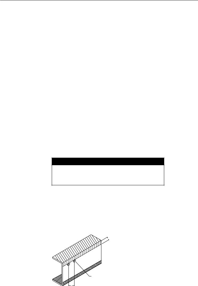
5.When welding the insert (length AL for wheelbase lengthening) to the original frame rail, a continuous butt weld must be used at the splices. When shortening the wheelbase, weld the ends of the chassis frame together with a continuous butt weld over the junction of the frame ends. Weld both the inside and outside of the frame rails using welding techniques prescribed by established welding standards (ref. SAE J1147) and in accordance with this guide. An example of this weld is shown below.
1.0 in. or more
BUTT WELD 100 % - Weld can be inside or outside of member or, as shown, a combination of both
1.0 in. or more
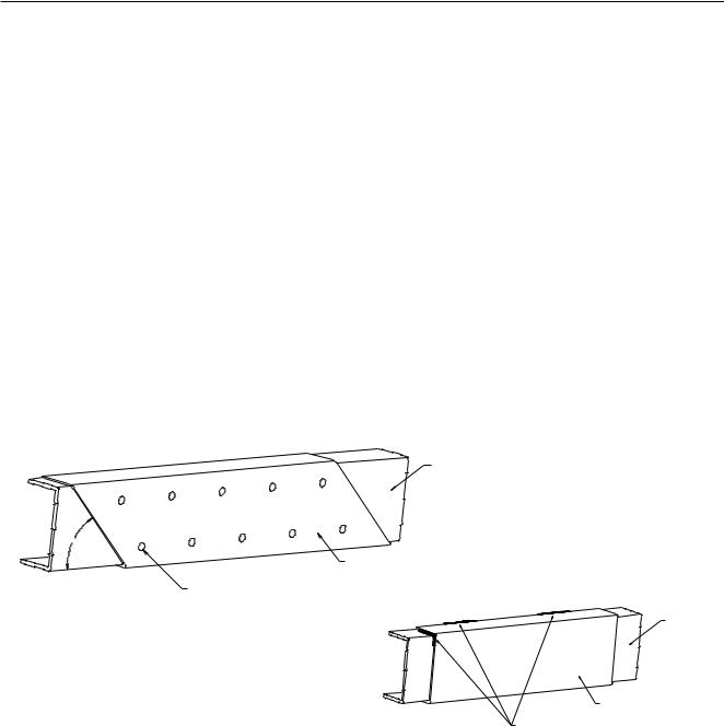
6. Determine the appropriate additional internal reinforcements which are required using this equation:
Reinforcement Length = AL + 6 x (original frame rail web depth).
The figure below shows how this reinforcement is to be placed over the extended or shortened section of the frame rail.
|
|
|
D |
|
3 x D |
AL |
3 x D |
3 x D |
3 x D |
|
|
|||
|
6 x D + AL |
|
|
6 x D |
|
|
|
|
|
|
Lengthened Wheelbase |
|
Shortened Wheelbase |
|
D = Original frame rail web depth
The suggested cross section of this reinforcement is a snug fit inner channel. If the new wheelbase exceeds the upper limit of the optional wheelbases of this model, i.e.; a “long bridge”, it may be necessary to use an “inverted L” reinforcement in addition to the snug fit channel reinforcement (see figures below). Application Engineering should be consulted for approval of such cases. It should be noted that these methods of reinforcements, and any other methods which may be used, require a 45 degree angled cut at both ends to avoid stress concentrations in the frame (note the figures under item 7).
OR
Snug fit inner channel |
Snug fit inner channel with "Inverted L" for "Long Bridge" wheelbases |
April 2002 |
17 |
Installation of Body & Special Equipment
7.The reinforcements must be fastened securely to only the web of the original chassis frame rail. The reinforcement must be held rigidly in place using either HUC bolts, GRADE 8 bolts and hardened steel washers at both the bolt head and nut, or GRADE 8 flanged bolts and hardened steel washers at the nut. Below are some suggested bolt patterns. It should be noted that these bolt patterns must not align the bolts vertically, i.e.: the bolt pattern must be staggered.
8.Lengthening the frame will also require extending the brake lines, basic chassis electrical harnesses, excluding ABS wiring harness. It is recommended that the original brake lines be removed and replaced with brake lines of the same diameter as the original lines and of the appropriate length. The electrical harness must be extended in accordance with the ELECTRICAL WIRING AND HARNESSING section of this book.
9.The propeller shafts’ overall length will also need to be lengthened or shortened. If the extension is within the limits of the optional wheelbases of the respective model, the exact propeller shaft lengths and angles are given on or about Page 12 of the respective sections of this book. If the modified wheelbase exceeds the optional wheelbases of the respective model, the following guidelines must be adhered to:
A.Propeller Shaft Length
The maximum propeller shaft lengths (pin to pin) for the respective models are shown in the table below.
|
NPR |
NPR GAS |
NQR |
FRR |
|
|
|
|
|
Propeller |
|
|
|
|
Shaft |
3.25 |
3.0 |
3.0 |
4.0 |
Diameter (in) |
|
|
|
|
|
|
|
|
|
Maximum |
|
|
|
|
Propeller Shaft |
50.8 |
50.8 |
50.8 |
62.0 |
Length (in) |
|
|
|
|
|
|
|
|
|
18 |
April 2002 |
Installation of Body & Special Equipment
B. Propeller Shaft Angles
The maximum propeller shaft angles, with respect to the previous shaft, are shown in the table below.
|
NPR/W |
NPR/W GAS |
NQR/W |
FRR/WT |
|
|
|
|
|
Maximum Propeller |
|
|
|
|
Shaft Angle |
5.7o |
5.1o |
5.7o |
5.5o |
|
|
|
|
|
C.The propeller shaft angles must be designed such that the angles will cancel to avoid propeller shaft whip.
D.The propeller shaft yokes must be assembled such that the propeller shaft yokes are “in phase.” “In phase” means that the yokes at either end of a given propeller shaft assembly are in the same plane.
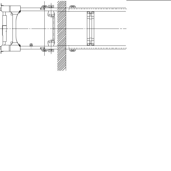
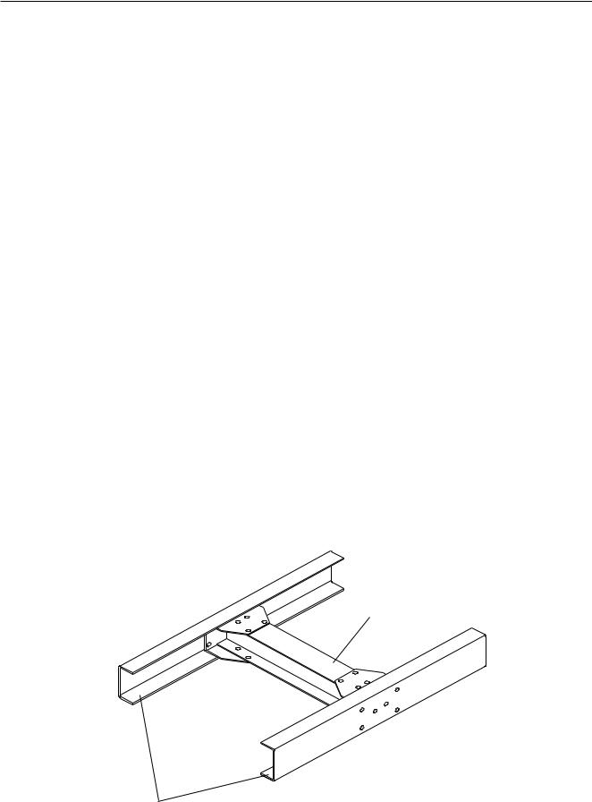
10.Extending the frame will also require relocation and/or addition of crossmembers. If the extension is within the limits of the optional wheelbases of the respective model, the exact cross member locations and dimensions are given in the respective model sections of this book. If the modified wheelbase exceeds the optional wheelbases of the respective model, the following guidelines must be adhered to:
A.The cross member location will largely be determined by the propeller shaft lengths and where the center carrier bearing locations are for the propeller shaft assembly.
B.A cross member must be located at the front and rear spring hangers of the rear suspension (refer to the appropriate section of this book to see where these suspension cross members are to be located).
C.The cross member must be constructed such that it supports both the upper and lower flange on each frame rail (see drawing below). A cross member such as the one below may be constructed, or Isuzu cross members may be obtained from your Isuzu parts dealer.
Additional crossmember
Frame rails
April 2002 |
19 |

Installation of Body & Special Equipment
D. The maximum distance between crossmembers for the respective models is given in the table below.
|
NPR/W |
NPR/W GAS |
NQR/W |
FRR/WT |
|
|
|
|
|
Maximum Distance |
35.7 |
35.7 |
35.7 |
49.8 |
Between Cross |
|
|
|
|
Members (in) |
|
|
|
|
|
|
|
|
|
E.The drilling for any additional holes in the frame rails must comply to the DRILLING AND WELDING section of this book.
11.All other aspects of lengthening or shortening the wheelbase must comply with the applicable section of this Body Builder's Guide. For special applications and longer than recommended body lengths, GMICT Application Engineering must be consulted for approval. In the West Coast call 1-562-229-5314 and in the East Coast call 1-404-257-3013
12.Please contact applications engineering for guidelines on N/W SERIES CHASSIS frame modifications when the vehicle is equipped with an Antilock Brake System.
FRR SERIES CHASSIS
Please contact applications engineering for guidelines on FRR SERIES CHASSIS frame modifications when the vehicle is equipped with an Antilock Brake System
FSR FTR FVR
WHEN MAKING WHEELBASE MODIFICATIONS TO THE 1997, MODEL YEAR AND ABOVE FSR, FTR, AND FVR HYDRAULIC BRAKE CHASSIS AND AIR BRAKE CHASSIS THE FOLLOWING SHOULD BE STRICTLY OBSERVED.
13.The Crew Cab NPR HD/W4500 and NQR/W5500 will be available in two wheelbases, 150 and 176 inches. Effective CA will be 84.7 and 110.7 inches. On this model chassis General Motors Isuzu Commercial Trucks will require that the body installed on the chassis have an understructure manufactured with any of the following structural steel "C" channels:
4"x1-5/8", 7.25 lbs/ft = ok 5"x1-3/4", 6.7 or 9.0 lbs/ft = ok 6"x2", 8.2, 10.5 or 13.0 lbs/ft = ok
HYDRAULIC BRAKE SYSTEM
1. BEFORE WORK BEGINS
As with any electrical work on the chassis the battery should be disconnected before electrical work is started.
2. ABS PROGRAM
The antilock brake system (ABS) computer will hold its codes when disconnected and reprogramming as a result of battery disconnection will not be necessary. If the wheelbase is changed the trim level of the ABS system must be readjusted per the instructions in the service manual. An Authorized Isuzu dealer should do this reprogramming using appropriate tools.
For your reference and to help you determine if the system needs to be reprogrammed the following provisions apply to all ABS systems with hydraulic brakes. The ABS module has four (4) programs: A, B, C, and D. These programs are tied to the wheelbase and axle combination of the chassis. (The axle and wheel base codes can be found on the passenger’s visor.)
A is for the FL1 axle and covers wheelbase from 140 (FQT), 158 (EG5), 170 (EH8) inches.
B is for the FL2 axle and covers wheelbase from 140 (FQT), 158 (EG5), 170 (EH8), 188 (EK8), 200 (EM2) inches.
20 |
April 2002 |
Loading...