


 Loading...
WORKSHOP MANUAL
727 (N SERIES)
ENGINE CONTROL SYSTEM
(4HK1 ENGINE)
SECTION 1A
International Service & Parts
Tokyo, Japan
N O T I C E
Before using this Workshop Manual to assist you in performing vehicle service and maintenance operations, it is recommended that you carefully read and thoroughly understand the information contained in Section - 0A under the headings “GENERAL REPAIR INSTRUCTIONS” and “HOW TO USE THIS MANUAL”.
All material contained in this Manual is based on the latest product information available at the time of publication.
All rights are reserved to make changes at any time without prior notice.

Engine Control System 1A-1
ENGINE
Engine Control System
CONTENTS
Engine Control System . . . . . . . . . . . . . . . . . . . . 1A-2 Precautions on Service . . . . . . . . . . . . . . . . . . . 1A-2 Function and Operation. . . . . . . . . . . . . . . . . . . 1A-4 Component Layout . . . . . . . . . . . . . . . . . . . . . 1A-20 Circuit diagram . . . . . . . . . . . . . . . . . . . . . . . . 1A-25 Strategy-Based Diagnostics . . . . . . . . . . . . . . 1A-31 Functional Check List . . . . . . . . . . . . . . . . . . . 1A-37 Hearing Diagnostic . . . . . . . . . . . . . . . . . . . . . 1A-37 On-Board Diagnostic (OBD) System Check . . 1A-39 Inactive CHECK ENGINE Lamp (MIL) . . . . . . 1A-41 CHECK ENGINE Lamp (MIL) Remains Active 1A-44 Engine Cranks But Will Not Run . . . . . . . . . . . 1A-46 Diagnosis with Tech 2 Scan Tool. . . . . . . . . . . 1A-48 Diagnostic Chart . . . . . . . . . . . . . . . . . . . . . . . 1A-67 DTC11 - No Signal CKP Sensor . . . . . . . . . . . 1A-73 DTC13 - TCV Fault . . . . . . . . . . . . . . . . . . . . . 1A-75 DTC14 - Pump ROM Fault . . . . . . . . . . . . . . . 1A-78 DTC15 - Pump Cam Sensor (NE Sensor)
Short Break Fault . . . . . . . . . . . . . . . . . . . . . . 1A-80 DTC16 - No Signal from Pump Cam Sensor
(NE Sensor) . . . . . . . . . . . . . . . . . . . . . . . . . . 1A-82 DTC21 - ECT Sensor Fault . . . . . . . . . . . . . . . 1A-84 DCT23 - IAT Sensor Fault. . . . . . . . . . . . . . . . 1A-88 DTC24 - AP Sensor Output Fault . . . . . . . . . . 1A-91 DTC25 - VS Sensor Circuit Fault . . . . . . . . . . 1A-95 DTC31 - Idle Up Volume Fault . . . . . . . . . . . . 1A-98 DTC32 - MAP Sensor Fault . . . . . . . . . . . . . 1A-101 DTC34 - Exhaust Brake Open Wiring Fault . 1A-104 DTC35 - Neutral Switch Signal Fault . . . . . . 1A-106 DTC36 - Clutch Switch Signal Fault
(M/T Vehicle only) . . . . . . . . . . . . . . . . . . . . . 1A-108 DTC41 - FT Sensor Circuit High Voltage . . . 1A-110 DTC51 - Atmospheric Pressure Sensor Fault 1A-113 DTC52 - ECM Internal Fault . . . . . . . . . . . . . 1A-114 DTC53 - Engine Driver Unit Fault . . . . . . . . . 1A-116 DTC55 - Pump Unmatched
(Difference from ECM Specifications) . . . . . . 1A-118 DTC65 - Idle Position Switch Fault . . . . . . . . 1A-120 Symptom Diagnosis Chart . . . . . . . . . . . . . . 1A-122 Hard Starting . . . . . . . . . . . . . . . . . . . . . . . . . 1A-123 Vehicle Speed Variation . . . . . . . . . . . . . . . . 1A-127 Lack Power or Faulty Response . . . . . . . . . . 1A-130 Unstable Idling . . . . . . . . . . . . . . . . . . . . . . . 1A-134 Engine Not Stall . . . . . . . . . . . . . . . . . . . . . . 1A-137 Starter Motor does Not Run . . . . . . . . . . . . . 1A-139 Quick On Start (QOS) System does Not
Operate . . . . . . . . . . . . . . . . . . . . . . . . . . . . . 1A-142 Excessive Black Smoke in Exhaust Gas. . . . 1A-144 Excessive White Smoke in Exhaust Gas . . . 1A-147 Noisy Engine . . . . . . . . . . . . . . . . . . . . . . . . . 1A-149 Nasty Smell. . . . . . . . . . . . . . . . . . . . . . . . . . 1A-152
Poor Fuel Economy. . . . . . . . . . . . . . . . . . . . 1A-155
Excessive Engine Oil Consumption . . . . . . . 1A-159
Large Engine Vibration . . . . . . . . . . . . . . . . . 1A-161
Special Tools . . . . . . . . . . . . . . . . . . . . . . . . . 1A-164
Wiring Harness Repair: Shielded Cable. . . . . . 1A-165
Removal Procedure . . . . . . . . . . . . . . . . . . . 1A-165
Installation Procedure . . . . . . . . . . . . . . . . . . 1A-165
Twisted Leads . . . . . . . . . . . . . . . . . . . . . . . . . 1A-166
Removal Procedure . . . . . . . . . . . . . . . . . . . 1A-166
Installation Procedure . . . . . . . . . . . . . . . . . . 1A-166
Weather-Pack Connector . . . . . . . . . . . . . . . . . 1A-168
Removal Procedure . . . . . . . . . . . . . . . . . . . 1A-168
Installation Procedure . . . . . . . . . . . . . . . . . . 1A-168
Special Tools . . . . . . . . . . . . . . . . . . . . . . . . . 1A-169
Com-Pack III. . . . . . . . . . . . . . . . . . . . . . . . . . . 1A-170
General Information . . . . . . . . . . . . . . . . . . . 1A-170
Metri-Pack . . . . . . . . . . . . . . . . . . . . . . . . . . . . 1A-171
Removal Procedure . . . . . . . . . . . . . . . . . . . 1A-171
Installation Procedure . . . . . . . . . . . . . . . . . . 1A-171
Special Tools . . . . . . . . . . . . . . . . . . . . . . . . . 1A-171

1A-2 Engine Control System
Engine Control System
Precautions on Service
Circuit Test Tools
Unless otherwise specified in diagnostic procedures, do not use Test Light to diagnose the powertrain electrical system. When diagnostic procedures need probe connector, use Connector Test Adapter Kit 5- 8840-0385-0.
On-Market Electrical Equipment and Vacuum Devices
On-market electrical equipment and vacuum devices refer to those components that will be installed to vehicles after shipment from manufacturing plants. Be careful that installation of these components is not considered during the process of vehicle design.
CAUTION:
Do not install on-market vacuum devices to vehicles.
CAUTION:
Connect on-market electrical equipment, as well as its power supplies and grounds, to the circuits isolated from the electronic control system.
The on-market electrical equipment, even when installed to vehicles in normal manner, may bring functional troubles to the electronic control system. Affected devices include those not connected to the vehicle electrical equipment system, for example, mobile phones or radios. Therefore, when you intend to diagnose the powertrain, check such the on-market electrical equipment has not been installed to the vehicle and, if installed, remove it. If faults still occur even after removal of on-market electrical equipment, diagnose the vehicle according to normal procedures.
List of Abbreviations
Damage by Electrostatic Discharge
Electronic components used in the electronic control system are designed to work at very low voltages and, for this reason, they are susceptible to damage by electrostatic discharge and some types of electronic components may be damaged even by the static electricity of less than 100 V that is usually not sensed by persons. Persons’ sensitivity level is 4,000 V. Persons are electrostatically charged in various ways and the most typical electrification sources are friction and induction. Shown below are examples.
•Electrification by friction occurs when a person slides on the seat in the vehicle.
•Electrification by induction occurs when a person with insulating shoes is standing near a highly electrifiable substance and touches a ground momentarily. Electric charges with the same polarity flow out and resultantly the person is charged at high opposite polarity. Since static electric charges cause damages, it is important when you handle or test electronic components.
CAUTION:
To prevent damages by electrostatic discharge, follow the guidelines shown below.
•Do not touch ECM connector pins as well as electronic components soldered to the ECM circuit board.
•Do not unpack each replacement component until preparations are completed for the component.
•Before taking out a component from the package, connect the package to the normal grounding line of the vehicle.
•When you intend to slide on the seat, change the posture from standing to sitting, or walk by a certain distance to handle a component, touch an appropriate grounding material.
Abbreviation |
Original form |
Meaning in this manual |
|
|
|
A/C |
Air Conditioner |
Air conditioning units (cooler, heater, etc.) |
|
|
|
AP |
Accelerate Position |
Depressing stroke of accelerator pedal |
|
|
|
CKP |
Crankshaft Position |
Rotating reference signal of crankshaft |
|
|
|
CMP |
Camshaft Position |
Rotating reference signal of pump camshaft |
|
|
|
DLC |
Data Link Connector |
DLC connector (Tech 2 communication connector) |
|
|
|
DTC |
Diagnosis Trouble Code |
DTC code |
|
|
|
DVM |
Digital Volt Meter |
Special service tool (part No. 5-8840-0366-0) |
|
|
|
ECT |
Engine Coolant Temperature |
Coolant temperature |
|
|
|
ECM |
Engine Control Modulle |
Engine control computer |
|
|
|
EDU |
Engine Driver Unit |
Fuel pump spill valve drive unit |
|
|
|

|
|
Engine Control System 1A-3 |
|
|
|
Abbreviation |
Original form |
Meaning in this manual |
|
|
|
EGR |
Exhaust Gas Recirculation |
Exhaust gas recirculation |
|
|
|
ISM |
Intake Step Motor |
Intake throttle valve drive motor |
|
|
|
ITP |
Intake Throttle Position |
Intake throttle valve opening |
|
|
|
MIL |
Malfunction Indicator Lamp |
CHECK ENGINE Lamp |
|
|
|
SPV |
Spill Control Valve |
Valve for high pressure circuit in the fuel pump |
|
|
|
SW |
Switch |
|
|
|
|
TCV |
Timing Control Valve |
Injection timing control valve in the fuel pump |
|
|
|
Key SW |
Key switch |
Starter switch |
|
|
|
Wire Color
All wiring harnesses are identified using colored jacket. The wiring harness used for the main circuit in an electrical system is identified with single color while the wiring harness used for the sub-circuit is identified with color stripe. The following rule is used in each wiring diagram to indicate size and color of a wiring harness.
eg. : 0.5 GRN / RED
1
2
3
LNW21ASH000101-X
Legend |
|
|
|
|
|
1. |
Red (stripe color) |
|
|
|
|
2. |
Green (base color) |
|
|
|
|
3. |
Harness size (0.5 mm2) |
|
|
|
|
|
|
|
|
|
|
|
Symbol |
Color |
|
Symbol |
Color |
|
|
|
|
|
|
|
B |
Black |
|
BR |
Brown |
|
|
|
|
|
|
|
W |
White |
|
LG |
Light green |
|
|
|
|
|
|
|
R |
Red |
|
GR |
Gray |
|
|
|
|
|
|
|
G |
Green |
|
P |
Pink |
|
|
|
|
|
|
|
Y |
Yellow |
|
LB |
Light blue |
|
|
|
|
|
|
|
L |
Blue |
|
V |
Violet |
|
|
|
|
|
|
|
O |
Orange |
|
|
|
|
|
|
|
|
|
1A-4 Engine Control System
Function and Operation
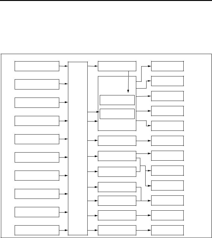
Electronic Control System
The electronic control system processes the data, which has been collected with various types of sensors, by means of the control program installed to ECM (engine control module) to totally control engine parameters such as fuel injection amount, injection timing, engine startup, altitude compensation, and EGR.
Sensor |
ECM |
Actuator |
Control |
Engine Rotating Speed |
|
Engine Driver Unit |
Fuel Injection Volume |
(Built-in Injection Pump) |
|
Control |
|
|
|
||
|
|
|
Fuel Injection Timing |
Crankshaft Position |
|
Injection Pump |
Control |
|
|
|
|
|
|
|
Idle Rotating Speed |
|
|
Spill Control Valve |
Control |
Accelerator Position |
|
|
|
|
|
|
|
|
|
Timing Control Valve |
Starting Control |
|
|
|
|
Coolant Temperature |
|
|
|
|
|
|
Altitude Control |
Fuel Temperature |
|
EGR Valve |
EGR Control |
(Built-in Injection Pump) |
|
||
|
Engine |
|
|
|
Control |
|
|
|
Module |
|
Intake Air Throttle |
Intake Air Pressure |
|
Intake Throttle Valve |
|
|
Control |
||
|
|
||
|
|
Exhaust Magnetic Valve |
Exhaust Brake Control |
|
|
|
|
Vehicle Speed |
|
|
|
|
|
Glow Plug |
Warm-Up System |
|
|
Control |
|
Idle Up Volume |
|
|
|
|
|
Glow Lamp |
Starting Aid Control |
Intake Air Temperature |
|
|
Self Diagnosis |
|
|
CHECK ENGINE Lamp |
|
Atmospheric Pressure |
|
Swirl Change-Over Valve |
Intake Air Swirl Control |
(Built-in ECU) |
|
||
|
|
LNW21ALF000301-X |
|
|
|
|
ECM
ECM Description
The ECM is mounted in the glove box. The ECM monitors various data sent from diversified sensors and controls systems in the powertrain. The ECM diagnoses these systems to detect faults with respect to system operations and inform the driver of faulty condition via the CHECK ENGINE Lamp (MIL) and stores DTCs (diagnostic trouble codes). DTC identifies the trouble generation area to aid repairs by service operators.
Function of ECM
ECM supplies 5 V and 12 V voltages to various sensors and switches. Since powers are supplied via high resistances in ECM, Test Light, even when connected to the circuit, will not be lit. In a special case, a normal voltmeter does not indicate correct values since the resistance of the instrument is too low. To get accurate readings, you need a digital voltmeter whose input impedance is at least 10 MΩ . The special tool 5-8840- 0366-0 is a proper choice for this measurement. In the ECM, the output circuit is controlled by regulating the
Engine Control System 1A-5
grounding system or power circuit via transistor or either of the devices listed below.
•Output driver module (ODM)
•Quad drive module (QDM)
ECM and Components
The ECM is designed to offer excellent drivability and fuel economy while achieving exhaust gas emission control requirements. The ECM monitors engine and vehicle functions via various electronic sensors such as CKP (crank position) and VS (vehicle speed) sensors.
Voltages from ECM
The ECM supplies reference voltages to various switches and sensors. Resistances of the ECM are very high and this allows the ECM to supply voltages to these devices, and voltages actually applied to circuits are low and even connecting Test Light to individual circuits may fail turn-on. Since the voltmeter normally used in service factories has low input impedance, correct readings may not be obtained. To get accurate readings, a digital voltmeter whose input impedance is 10 MΩ (for example, 5-8840-0366-0) should be used.
Input/output devices of the ECM include analog-to- digital converter, signal buffer, counter, and special driver. By using electronic switches, the ECM controls most system components and turning off a switch closes the ground circuit. These switches are divided into four-switch or seven-switch groups, and the former group is called quad driver module (QDM) and controls up to four output pins respectively while the latter group is called output driver module (ODM) and controls up to seven outputs respectively. Note that all the outputs are necessarily not used in the control.
Electrically Erasable Programmable ROM (EEPROM)
EEPROM is a permanent memory chip and soldered to the board in the ECM. EEPROM stores program and calibration data, both of which are necessary for the ECM to control the powertrain. Different from conventional ROMs, EEPROM cannot be replaced with new component. If EEPROM fails, the complete ECM assembly must be replaced with new one.
Precautions on ECM Service
The ECM is designed to withstand ordinary currents used in operations of a vehicle. Be careful that the circuits must not be overloaded. To test the ECM to check open wiring or short, ECM circuits must be connected to the ground or voltages must not be applied to the ECM. To test ECM circuits, the digital voltmeter 5-8840-0366-0 should always be used.
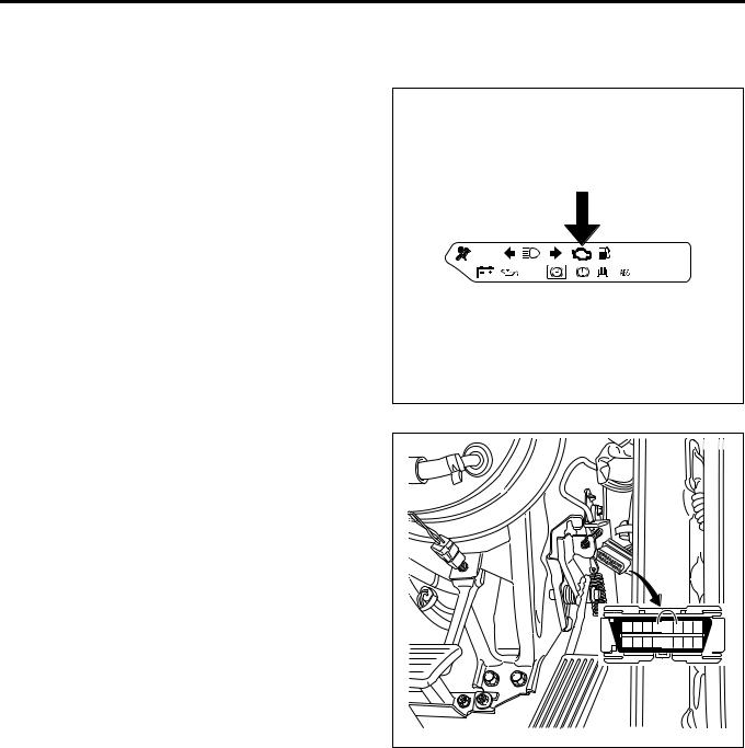
CHECK ENGINE Lamp (MIL)
Used as a means of communication between ECM and user usually in the user mode, by light on and off. If this lamp illuminates during operation, it warns some
engine fault to the user.
In a service factory, 4 pins and 6 pins of DLC (data link connector) can be short to check the DTC while the CHECK ENGINE Lamp (MIL) is flashing.
|
|
|
LNW21ASH000201 |
||||
1 |
2 |
3 |
4 |
5 |
6 |
7 |
8 |
9 |
10 11 12 13 14 15 16 |
||||||
|
|
|
LNW21ASH000301 |
||||
1A-6 Engine Control System
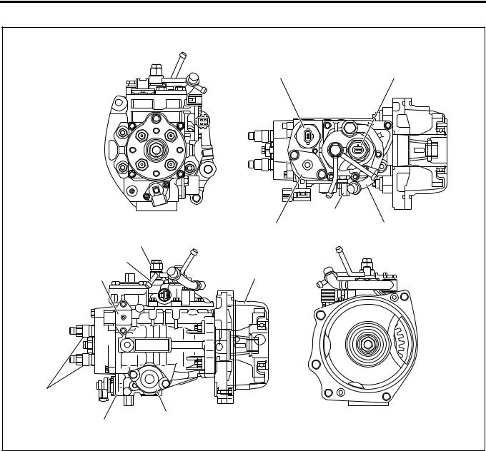
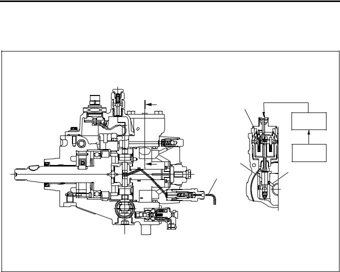
Electronically Controlled Distributor Injection Pump
|
1 |
2 |
|
|
4 |
|
5 |
3 |
|
12 |
|
|
11 |
|
10 |
6 |
|
|
|
|
9 |
|
|
|
7 |
|
8 |
|
|
|
|
LNW21ALF000101 |
Legend |
|
|
|
1. |
Spill control valve |
7. |
Timer |
2. |
Pump cam position sensor (engine speed |
8. |
Timing control valve |
|
sensor) |
9. |
Delivery valve holder |
3. |
Inlet pipe |
10. |
Compensation ROM |
4. |
Fuel temperature sensor |
11. |
Overflow pipe |
5. |
Accumulator |
12. |
Overflow valve |
6. |
Bearing cover |
|
|
|
|
|
|
An electronically controlled distributor injection pump is employed to meet the requirements of the long-term exhaust gas control without impairing the fuel efficiency and output. These features allow finer particles of injected fuel, and optimum injection timing and injection amount while the vehicle is traveling, which was impossible with the former injection pump.
Fuel Dehumidifying Agent
Sliding parts in the injection pump are lubricated by the fuel (light oil) as in the existing distributor type injection pump. If dehumidifying agent is mixed in the fuel, it may exert adverse influence on the sliding parts. Particularly, dehumidifying agent of alcohol type is characterized by introducing moisture into water, causing rust generation. It should be explained to customers not to use fuel dehumidifying agent or other fuel additives.
Engine Control System 1A-7
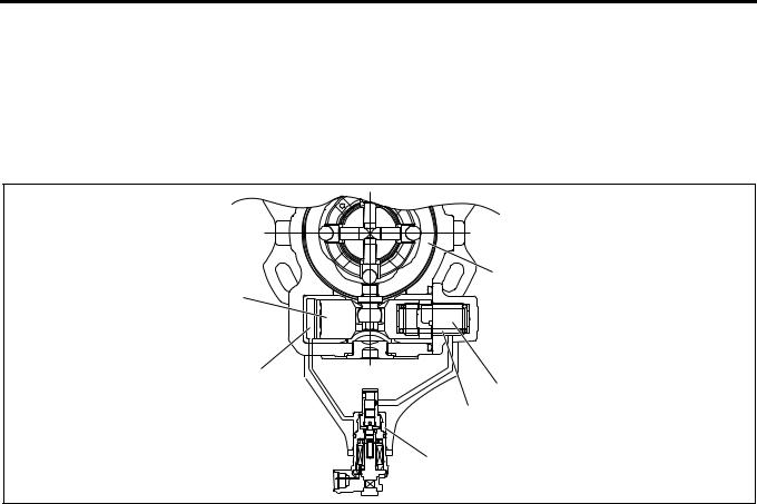
Structure and Operation
1.Higher pressure of injection fuel
An inner cam with a cam ring and radial plunger are used to increase the pressure of the injection fuel.
The cam ring is supported on the pump body side and provided with projections (cams) on the internal periphery.
Four plungers are provided at an interval of 90°, incorporated in the rotor integrated with the drive shaft, and in contact with the internal periphery of the cam ring in the radial direction through the roller.
When the drive shaft rotates, the plunger moves on the cam ring internal surface through the rolling of the roller, pushed out in the shaft center direction with the inner cam and compresses the fuel.
Four plungers operate simultaneously. This enables higher pressure (75 ~ 130 MPa) and high rigidity is obtained since the load becomes relative load in the radial direction.
Plunger diameter is ø7.5mm and the cam lift is 2.5mm.
1
5


 2 4
2 4 


3
LNW21ASH000401
Legend
1.Cam ring
2.Rotor
3.Timer piston
4.Roller
5.Plunger
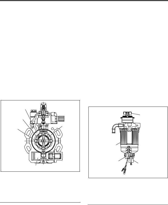
2.Injection timing control
Injection timing is adjusted by shifting the cam ring phase with the fuel pressure applied to the back of the timer piston. The fuel pressure applied to the timer piston is controlled with the ECM (engine control module) through the timing control valve.
3.Fuel injection amount control
Fuel injection amount is adjusted by opening or closing the fuel high pressure circuit with the high response SPV (spill control valve).
EDU (engine driver unit; a high voltage driver) is employed to drive the SPV at a high speed. EDU can drive the SPV of high fuel pressure at a high speed by the high voltage and high speed energizing system.
4.Pump ROM
In order to compensate the variation of correlation between the fuel pump and engine, variation of the injection amount inherent to the injection pump is corrected.
5.Air bleeding of injection pump
a.Pumping until the pump is hard to operate.
b.Start the engine. If not started, repeat pumping.
c.After the engine is started, keep the engine speed at 1000 to 1500rpm for about 10 seconds.
d.Stop the engine.
e.Check for fuel leakage.
1
4
3
2
LNW21ASH000501
Legend
1.Priming pump
2.Plug
3.Sensor
4.Cartridge
1A-8 Engine Control System
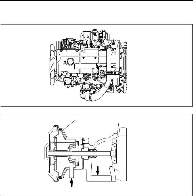
EGR (Exhaust Gas Recirculation) Valve
In order to decrease NOx (nitrogen oxide) in the exhaust gas, an EGR system is employed.
The EGR valve is vacuum control type.
LNW21ASF000101
1
2
 3
3
3
4
LNW21ASF000201
Legend |
|
|
|
1. |
Diaphragm |
3. |
Exhaust gas |
2. |
Valve |
4. |
Vacuum |
|
|
|
|
Engine Control System 1A-9
Injection Nozzle
1 |
LNW21ASF000301 |
Legend
1. Edge filter
A two-step valve opening pressure nozzle is used as the injection nozzle. Spray particle size is reduced by reducing the injection hole diameter.
To prevent clogging of the nozzle injection hole, an edge filter is provided at the nozzle holder inlet.
Reference:
If the injection nozzle hole is clogged, ECM corrects the cylinder inside condition.
The cylinder correction amount in the Tech 2 data list is helpful to know the injection nozzle condition.
|
Item |
Engine 4HK1 |
|
|
|
|
|
Valve |
1st valve opening |
18.0 {185} |
|
opening |
pressure |
(Nominal value) |
|
pressure |
|
|
|
2nd valve |
22.0 {225} |
||
MPa(kg/cm2) |
|||
opening pressure |
(Nominal value) |
||
|
|
|
|
No. of injection holes - Injection |
5 -ø0.25 |
||
hole diameter (mm) |
|
||
|
|
|
|
Fuel Filter with Sedimentor
In order to secure the lubrication efficiency in the injection pump, a fuel filter with sedimentor to remove moisture in the fuel is provided.
This filter is provided with a priming pump to bleed the air from the injection pump.
1
2
LNW21ASH000601
Legend
1.Priming pump
2.Fuel filter & sedimentor
1A-10 Engine Control System
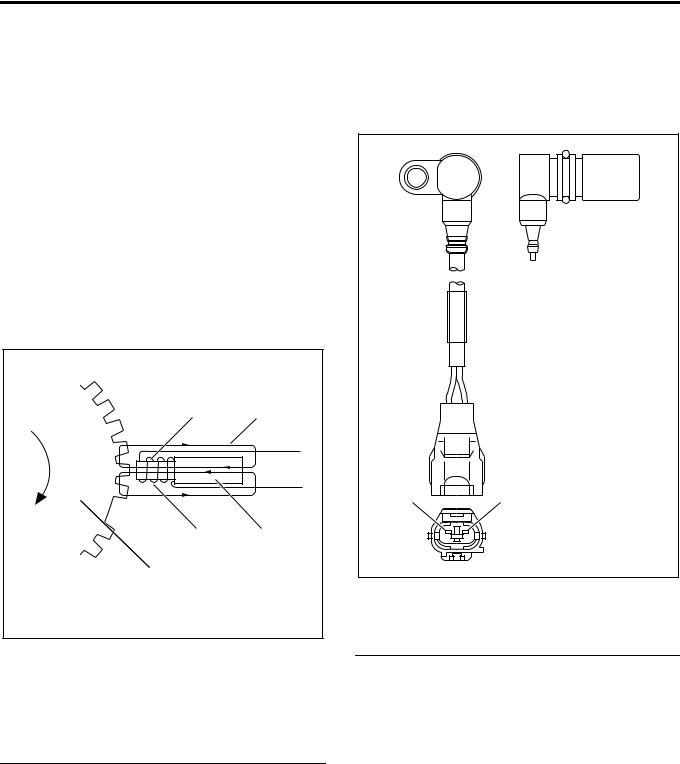
Pump CMP (Cam Position) Sensor (Engine Rotation Sensor ) = NE Sensor
The pump CMP sensor is positioned on the outer surface of the cam ring of the pump chamber. The pulser installed to the injection pump drive shaft interrupts the magnetic flux generated by the permanent magnet and iron core of the sensor according to the shaft rotation to generate AC wave signal to the coil. This is transmitted to ECM (engine control module) and converted to square wave signal. engine speed and cam position are calculated by this signal.
• Calculation of engine speed: No. of pulses per hour is counted.
• Calculation of cam position: When the cam ring slides, timing of signal read from the pulse of the sensor installed to the cam ring varies. ECM calculates the time difference between this signal and signal of the crank position sensor and calculates the cam position.
1 2
4 3
5
LNW21ASH000701
Legend
1.Iron core
2.Magnetic flux
3.Permanent magnet
4.Coil
5.Pulser
CKP (Crank Position) Sensor
CKP sensor to detect the crank position is installed to the flywheel housing. The sensor detects the rotating angle of the crankshaft in non-contact condition with the pointer installed to the flywheel and sends pulse signal to ECM. ECM calculates the injection timing at the pump cam position based on this pulse signal.
12
LNW21AMH000101
Legend
1.(–) Pin
2.(+) Pin
Engine Control System 1A-11
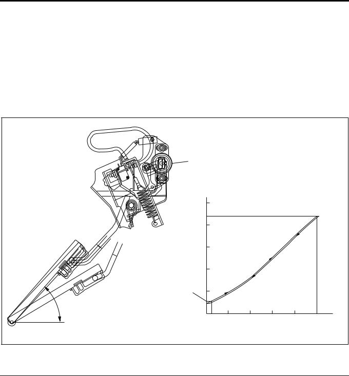
Accelerator Position Sensor
The accelerator control is accelerator position sensor type. This sensor is a potentiometer (variable resistance) installed to the accelerator pedal. Reference voltage is constantly applied to the sensor from ECM (engine control module) and the accelerator pedal stepping angle is detected from varying voltage. An accelerator switch (idle position switch) is also installed to the accelerator pedal. The accelerator switch is turned ON when the accelerator pedal is released and OFF when the accelerator pedal is stepped on.
1 |
|
|
|
|
|
|
|
(V) |
|
|
|
|
|
|
5 |
|
|
|
|
|
(WOT) |
|
|
|
|
|
|
|
4 |
|
|
|
|
|
Voltage |
3 |
|
|
|
|
|
|
|
|
|
|
|
|
Output |
2 |
|
|
|
|
|
|
|
|
|
|
|
|
2 |
1 |
|
|
|
|
|
49 |
(Idle) |
|
|
|
|
|
|
0 |
10 |
20 |
30 |
40 |
50 (mm) |
|
|
|||||
|
|
|
Stroke (on Pedal) |
|
||
|
|
|
|
|
|
LNW21AMF000701-X |
Legend |
|
1. Accelerator position sensor |
2. Accelerator switch operating point |
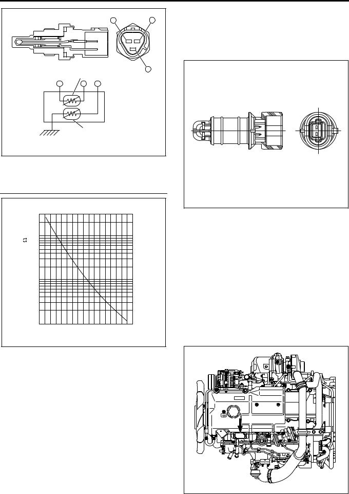
Engine Coolant Temperature Sensor (Coolant Temperature Sensor / ECT)
The engine coolant temperature sensor serves for both the ECM and thermo meter unit. The engine coolant temperature sensor is of the thermistor type that the electric resistance reduces with the increase of the temperature. It is installed on the left front of the cylinder head.
1A-12 Engine Control System
|
|
A |
C |
|
|
|
B |
|
1 |
|
|
A |
C |
B |
|
|
2 |
|
|
|
|
|
LNW21ASH000801 |
Legend
1.Thermistor for ECM
2.Thermistor for thermo meter
[Thermistor Characteristics]
|
30 |
|
|
20 |
|
) |
10 |
|
(k |
7.0 |
|
5.0 |
||
Value |
||
3.0 |
||
Resistance |
||
2.0 |
||
|
1.0
0.7
0.5
0.3
0.2
0.1
-20 0 20 40 60 80 100 120
Engine Coolant Temperature ( C)
LNW21ASH000901-X
Fuel Temperature Sensor
Fuel temperature sensor is installed in the pump chamber full of fuel. Thermistor is used for the temperature detector as in the thermo sensor and convert the changes of temperature to changes of resistance and values transmits to ECM.
Vehicle Speed Sensor
The vehicle speed sensor is used commonly with the speedometer. ECM receives signal from the speedometer.
By one turn of the speedometer driven gear, 25 pulses are generated indicating 60 km/h at 637rpm.
Intake Air Temperature Sensor
Intake air temperature sensor is installed to the intake duct. Thermistor is used for the temperature detector as in the thermo sensor to convert the changes of temperature to changes of resistance values and transmits to ECM.
LNW21ASH001001 |
Atmospheric Pressure Sensor
The atmospheric pressure sensor is incorporated in ECM.
MAP (Intake Air Pressure) Sensor
The MAP sensor is installed to the cylinder head cover. The MAP sensor is composed of piezo type semiconductor pressure element. Reference voltage is constantly applied to the MAP sensor from ECM and manifold pressure is detected by the changes of voltage. When the manifold pressure is low (at idling), low voltage signal is sent to ECM and when the pressure is high (at full throttle), high voltage signal is transmitted to ECM.
LNW21ASH001101 |
Engine Control System 1A-13
MAP (Intake Air Pressure) Sensor
|
Output Voltage (V) |
[MAP Sensor Characteristics] |
|
|
|
|
|
|
|
6 |
|
Absolute |
|
|
|
Pressure |
|
|
|
|
|
1 |
2 |
|
|
|
5 |
4 |
3 |
|
|
|
|
|
|
|
|
|
LNW21AMF000801-X |
|
|
|
|
|
|
|
|
|
Legend |
|
|
|
|
|
||
1. |
Pressure at idling (low pressure) |
4. |
Output pin |
||||
2. |
Pressure at rating point (absolute pressure (high |
5. |
Ground pin |
||||
|
|
pressure)) |
|
|
6. |
Vacuum hose connected pipe |
|
3. |
Power pin |
|
|
|
|
|
|
|
|
|
|
|
|
|
|
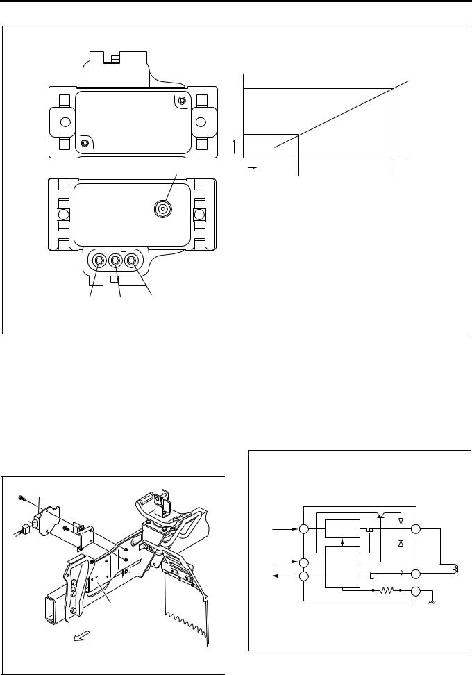
EDU (Engine Driver Unit)
EDU enables SPV high speed drive at high fuel pressure by the high voltage and high speed energizing system.
Maximum charging voltage is about 150V.
1 |
2 |
LNW21ASH001201 |
Legend
1.EDU
2.Left side cover
Connecting Diagram |
|
|
|
Battery |
High Voltage |
D SPV+ |
|
A |
Generating |
||
|
Circuit |
|
|
ECM |
Control |
|
|
B |
|
|
|
ECM |
Circuit |
E |
|
C |
|
SPV |
|
|
|
||
|
|
|
|
|
|
F |
Ground |
|
|
|
|
|
|
LNW21ASH001601-X |
|
1A-14 Engine Control System
SPV (Spill Control Valve)
Fuel injection amount is controlled with the highresponse SPV by opening and closing the fuel high pressure circuit.
SPV is incorporated in the injection pump.
B |
1 |
|
7 |
||
|
||
|
2 |
|
|
3 |
|
B |
5 |
|
4 |
||
|
||
|
6 |
|
|
8 |
|
|
LNW21AMF000901 |
Legend |
|
|
|
1. |
SPV drive signal |
5. |
Valve |
2. |
EDU |
6. |
High pressure fuel passage |
3. |
ECM |
7. |
SPV |
4. |
High pressure fuel |
8. |
B-B section |
|
|
|
|
Engine Control System 1A-15
TCV (Timing Control Valve)
TCV using a solenoid valve is installed to the oil pressure timer. Duty (energizing rate) controlled current with ECM increases or decreases the valve opening time to control the oil pressure in the high pressure chamber side. The timer piston is moved by the balance with the timer spring. By sliding the cam ring connected movably with the timer piston in the rotating direction, the injection timing is controlled.
1
6
5
2
3
4
7 
LNW21ASF000401
Legend |
|
|
|
1. |
Cam ring |
5. |
High pressure chamber |
2. |
Low pressure chamber |
6. |
Timer piston |
3. |
Timer spring |
7. |
From ECM |
4. |
TCV |
|
|
|
|
|
|
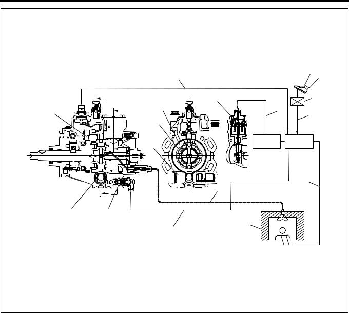
Electronic Control Distributor Pump System System Overview
The accelerator control uses an accelerator position sensor. The accelerator sensor of the potentio meter (variable resistance) type is installed to the accelerator pedal. Reference voltage is constantly applied to the sensor from the ECM (engine control module) to detect the accelerator pedal stepping angle from changes of voltage. An idle position switch (accelerator switch ) is also installed to the accelerator pedal. The idle position switch (accelerator switch ) is turned ON when the accelerator pedal is released and OFF when the accelerator is stepped on.
ECM detects the accelerator pedal stepping angle as AP (accelerator position) signal and after calculating, transmits SPV (spill controller valve) drive signal to EDU (engine driver unit).
EDU enables high speed drive of SPV which controls fuel injection amount.
The fuel injection amount is controlled by opening and closing the fuel high pressure circuit with the high response SPV.
SPV is incorporated in the injection pump.
The spill control valve and timing control valve are
electronically controlled with ECM (engine control module).
1A-16 Engine Control System
|
|
|
4 |
|
|
A |
|
5 |
10 |
|
|
|
||
|
|
|
|
|
|
|
B |
3 |
6 |
17 |
|
|
||
|
|
|
9 |
|
|
|
|
|
|
|
|
|
2 |
|
|
|
|
7 |
8 |
|
|
B |
1 |
|
|
|
|
|
|
|
|
|
19 |
|
|
|
|
|
11 |
|
A |
|
13 |
|
|
|
18 |
|
|
|
|
|
|
|
16 |
15 |
|
|
|
|
|
|
12 |
|
|
|
|
14 |
|
|
|
|
|
LNW21ALF003101 |
Legend |
|
|
|
1. |
Timer piston |
11. |
Crankshaft position signal |
2. |
Plunger |
12. |
Engine |
3. |
Cam ring |
13. |
High pressure fuel passage |
4. |
Pump cam position signal (engine speed signal) |
14. |
Injection timing control signal |
5. |
Spill control valve |
15. |
Timing control valve |
6. |
Spill control valve drive signal |
16. |
Timer piston |
7. |
Engine driver unit |
17. |
Pump cam position sensor (engine speed |
8. |
Engine control module |
|
sensor) |
9. |
Accelerator pedal opening signal |
18. |
A-A section |
10. |
Accelerator position signal |
19. |
B-B section |
|
|
|
|
Fuel Injection Amount Control
The electromagnetic spill valve is opened by the signal from ECM (engine control module), pressure in the fuel forced feed unit (rotor unit) is decreased and injection is completed. Injection amount is controlled at this timing.
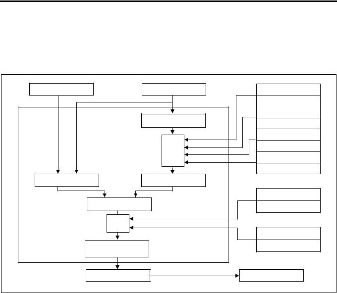
Engine Control System 1A-17
Operation
ECM calculates the basic injection amount optimum to the engine operating conditions and the maximum injection amount at that engine condition, compares and selects lower injection amount. By adding the phase compensated with the compensation ROM to that injection amount, the final injection amount is determined.
At the time of start, the optimum fuel injection amount is determined by the starter signal and coolant temperature. (Injection amount increases more when the coolant temperature is lower.)
Accelerator Position |
Engine Speed Sensor |
Intake Air Pressure |
Sensor |
|
Sensor |
|
|
Increase When Higher |
|
|
Intake Air Temperature |
|
Basic Max. Injection |
Sensor |
|
Varying Depending on |
|
|
Amount |
|
|
Conditions |
|
|
|
|
|
|
Fuel Temperature Sensor |
|
Compen- |
Increases When Lower |
|
|
|
|
sation |
Coolant Temperature |
|
|
Sensor |
|
|
Increases When Lower |
Basic Injection Amount |
Max. Injection Amount |
|
|
|
Fuel Temperature Sensor |
Select Lower Injection |
Compensates to Increasing |
|
Amount Side |
|
|
|
Side When Higher |
|
|
|
|
Compen- |
|
|
sation |
|
|
|
|
Compensation ROM |
Injection Amount |
|
Compensation Value |
|
of Each Pump |
|
Determine |
|
|
|
|
|
EDU |
|
Electromagnetic Spill Valve |
|
|
LNW21AMF001001-X |
1.Basic injection amount
Determined by accelerator opening and engine speed.
2.Max. injection amount
Maximum injection amount is determined by adding compensation by signals of sensors to the basic maximum injection amount (amount which can be theoretically injected) determined based on the engine speed.
a.Intake air pressure compensation
When the intake air pressure is high, the air amount is increased and the injection amount is increased.
b.Intake air temperature compensation
Injection amount is increased or decreased depending on the difference of density based on the intake air temperature.
c.Fuel temperature compensation
When the fuel temperature decreases, the injection amount is increased.
d.Coolant temperature compensation
When the coolant temperature is lower, the injection amount is increased to secure the operability immediately after the cold start.
3.Injection amount compensation
Since the actual injection amount decreases in comparison with the designated value of injection amount when the fuel temperature is higher, designated injection amount value is increased.
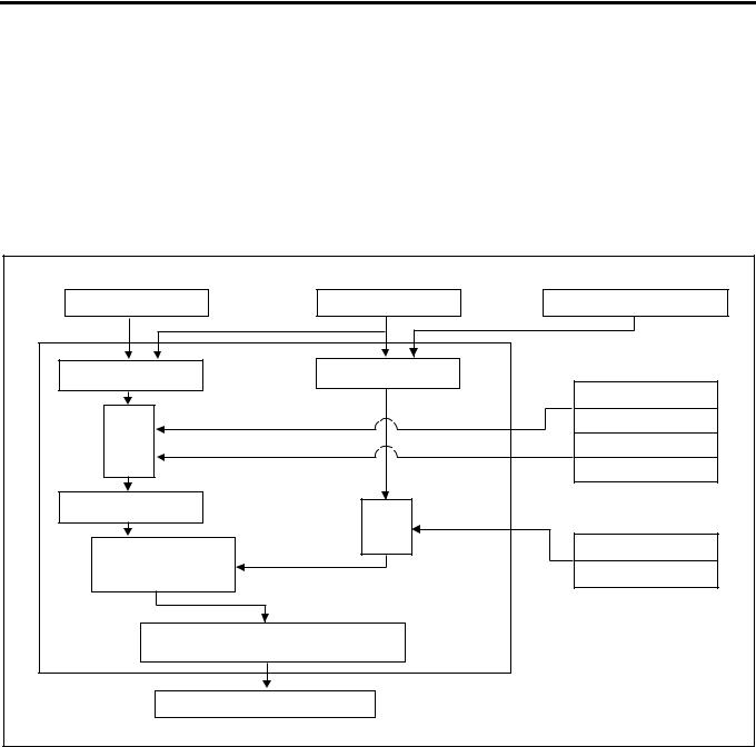
Fuel Injection Timing Control
•Timing control valve is duty-controlled according to a signal from ECM (engine control module) to control the fuel injection start timing.
•Using the crankshaft angle feed back system, highly precise control is effected.
1A-18 Engine Control System
Operation
ECM calculates the optimum target injection timing for the engine condition, adding the compensation by signals from sensors based on the basic target injection timing.
At the time of start, the injection timing is determined by the starter signal, coolant temperature and engine speed (at the higher engine speed, the injection timing angle advances.)
Crank angle feedback system is employed to calculate the actual injection timing and feed back the result at the target injection timing.
Accelerator Position |
Speed Sensor |
Crank Position Sensor |
|
Sensor |
|||
|
|
||
Basic Target Injection |
Actual Injection Timing |
|
|
Timing |
|
Intake Air Pressure |
|
|
|
||
|
|
Sensor |
|
|
|
Angle Advances |
|
Compen- |
|
When Lower |
|
|
Coolant Temperature |
||
sation |
|
||
|
Sensor |
||
|
|
Angle Advances |
|
|
|
When Lower |
|
Target Injection Timing |
Compen- |
|
|
|
|
||
|
sation |
|
|
Comparison with Target |
|
Compensation ROM |
|
|
|
||
Injection Timing and |
|
Compensation Value |
|
Actual Injection Timing |
|
of Each Pump |
|
Calculation of Duty Ratio |
|
||
Timing Control Valve |
|
||
|
|
LNW21AMF001101-X |
|
1.Basic target injection timing
Determined based on the accelerator opening and engine speed.
2.Injection timing compensation
a.Intake air pressure compensation
Basic target injection timing is compensated by the intake air pressure. When the atmospheric pressure is low on a altitude, for instance, the injection timing angle is advanced.
b.Coolant temperature compensation
Basic target injection timing is compensated based on the coolant temperature. When the coolant temperature is low, the injection timing angle is advanced.
3.Feedback control
a.Calculation of actual injection timing
When relation between the compression TDC position and crank angle reference position signal is correct on the engine side and the relation between the injection waveform and
cam angle signal is correct on the pump side, actual injection timing θ n can be calculated by calculating the phase difference θ i between the crank angle reference position signal and cam angle signal.
Engine Control System 1A-19
6
θ 
1
5
 θ
θ 
4
2
3
LNW21ASH001701
Legend
1.Engine
2.Pump
3.Injection waveform
4.Cam angle signal
5.Crank angle reference position signal
6.Actual compression TDC
b.Feedback control
Timing control valve duty ratio is calculated so that the actual injection timing coincides the target injection timing.
Idle Speed Control
•Idle speed is controlled by increasing or decreasing the specified fuel injection amount value based on the signal from ECM (engine control module).
Operation
1.Feedback control
When there is a difference between the target speed calculated by the ECM and engine speed at the idle speed, the fuel injection amount is controlled by changing the signal to the electromagnetic spill valve and controls so that the engine speed coincides the idle speed.
2.Warm-up control
Optimum fast idle engine speed is controlled at idling by the coolant temperature.
3.Estimated control
Immediately after changing over the air conditioning switch, before the engine speed changes, the injection amount is changed by a constant amount to prevent change of idle speed by the change of load given to the engine.
Idle Speed (P.N Range in A/T Vehicle) [r/min]
|
M/T |
A/T |
|
|
|
|
|
Engine speed at |
Approx. 580 |
Approx. 650 |
|
no load |
|||
|
|
||
|
|
|
|
Air conditioner |
Approx. 800 |
Approx. 870 |
|
system ON |
|||
|
|
||
|
|
|
1A-20 Engine Control System
Component Layout
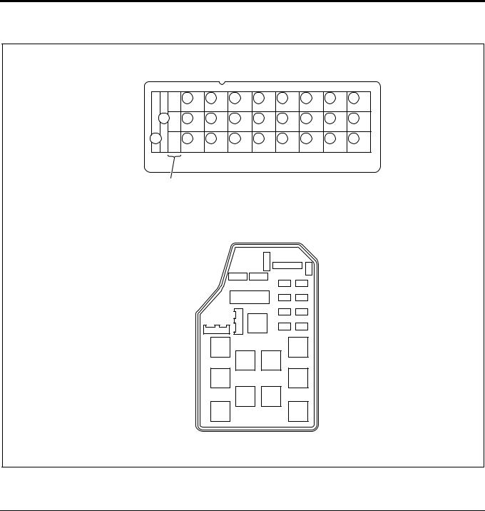
Fuse Layout
[Fuse Box Label, In Glove Box]
|
22 |
19 |
16 |
13 |
10 |
7 |
4 |
1 |
25 |
23 |
20 |
17 |
14 |
11 |
8 |
5 |
2 |
26 |
24 |
21 |
18 |
15 |
12 |
9 |
6 |
3 |
1
[Fuse Box, Front Left of Radiator]
27 28
LNW21ALF000401-X
Legend
1. Spare fuse
No. |
Indication on label |
Capacity |
Devices connected |
|
|
|
|
|
|
1 |
CONTROLLER |
10A |
Control unit |
|
|
|
|
|
|
2 |
HAZARD,HORN (12V) |
15A |
Hazard warning flashing lamp, horn |
|
|
|
|||
HAZARD,HORN (24V) |
10A |
|||
|
|
|||
|
|
|
|
|
3 |
— |
10A |
— |
|
|
|
|
|
|
4 |
AIR CON (12V) |
10A |
Air conditioner |
|
|
|
|
||
HEATER,AIR CON (24V) |
15A |
Heater, air conditioner |
||
|
||||
|
|
|
|
|
5 |
FUEL, SEAT HEATER (24V) |
10A |
Fuel, seat heater |
|
|
|
|
|
|
6 |
ABS, HAB, RETARDER (24V) |
15A |
ABS, HAB, retarder |
|
|
|
|
|
|
|
|
Engine Control System 1A-21 |
|
|
|
|
|
|
No. |
Indication on label |
Capacity |
Devices connected |
|
|
|
|
|
|
7 |
ROOM LAMP |
15A |
Room lamp |
|
|
|
|
|
|
8 |
STOP LAMP |
10A |
Stop lamp |
|
|
|
|
|
|
9 |
POWER WINDOW (24V) |
20A |
Power window |
|
|
|
|
|
|
10 |
TAIL.ILLUMI (12V) |
15A |
Tail lamp |
|
|
|
|||
TAIL.ILUMI (24V) |
10A |
|||
|
|
|||
|
|
|
|
|
11 |
FOG.CORNER |
10A |
Fog lamp, cornering lamp |
|
|
|
|
|
|
12 |
ELEC.PTO (24V) |
10A |
PTO switch (electric PTO) |
|
|
|
|
|
|
13 |
WIPER,WASHER |
15A |
Wiper, window washer |
|
|
|
|
|
|
14 |
TURN |
10A |
Turn signal lamp |
|
|
|
|
|
|
15 |
GENERATOR (12V) |
15A |
Generator |
|
|
|
|
||
ELEC.PTO (24V) |
20A |
PTO solenoid valve (electric PTO) |
||
|
||||
|
|
|
|
|
16 |
MIRROR HEAT (12V) |
10A |
Heated side mirror |
|
|
|
|
||
ENG.CONT (24V) |
15A |
ECM |
||
|
||||
|
|
|
|
|
17 |
MIRROR |
10A |
Electrically operated mirror |
|
|
|
|
|
|
18 |
CIGAR,AUDIO |
10A |
Cigarette lighter, audio |
|
|
|
|
|
|
19 |
METER (12V) |
10A |
Meter |
|
|
|
|||
METER (24V) |
15A |
|||
|
|
|||
|
|
|
|
|
20 |
ENGINE STOP (12V) |
10A |
Engine stop |
|
|
|
|
||
HSA (24V) |
10A |
HSA |
||
|
||||
|
|
|
|
|
21 |
AIR BAG |
10A |
SRS airbag |
|
|
|
|
|
|
22 |
STARTER |
10A |
Starter |
|
|
|
|
|
|
23 |
H/LAMP RH |
10A |
Headlamp, RH |
|
|
|
|
|
|
24 |
H/LAMP LH |
10A |
Headlamp, LH |
|
|
|
|
|
|
25 |
HEATER (12V) |
30A |
Heater |
|
|
|
|
||
ENG CONTROLLER (24V) |
30A |
ECM (except for turbocharged vehicles) |
||
|
||||
|
|
|
|
|
26 |
POWER WINDOW (12V) |
30A |
Power window |
|
|
|
|
|
|
External Fuse Box |
|
|
||
|
|
|
|
|
No. |
Indication on label |
Capacity |
Devices connected |
|
|
|
|
|
|
27 |
MARKER LAMP |
10A |
Marker lamp |
|
|
|
|
|
|
28 |
COND FAN |
10A |
Condenser fan |
|
|
|
|
|
|
1A-22 Engine Control System
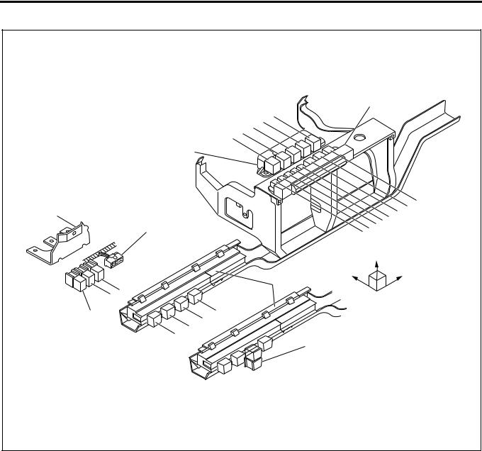
Relay Layout
|
|
Relay Box No.1 |
|||
|
13 |
|
|
|
|
|
16 15 14 |
|
|
|
|
|
18 |
|
|
|
|
Relay Box No.2 |
|
|
|
|
|
|
|
|
|
|
12 |
Bracket |
|
|
|
|
11 |
Spare Power Circuit |
|
|
6 |
7 |
8 9 10 |
|
|
5 |
|
||
|
|
|
|
|
|
|
|
Upper |
|||
|
Fuse & |
Front |
|
|
Right |
|
Relay Box |
|
|
||
|
|
|
|
|
|
19 20 |
|
|
|
|
|
Cooler Relay |
4 |
|
|
|
|
3 |
|
|
|
|
|
2 |
|
|
|
|
|
|
|
|
|
|
|
1 |
|
17 |
|
|
|
|
|
|
|
|
|
|
|
|
|
|
LNW21ALF006101-X |
No. |
|
Legend |
|
|
|
|
|
1 |
12 |
V: On relay |
|
|
|
||
24 |
V: Charge relay |
||
|
|||
|
|
||
2 |
Horn relay |
||
|
|
|
|
3 |
12 |
V: ABS, VSV, FICD, EXH brake |
|
|
|
||
24 |
V: Headlamp relay |
||
|
|||
|
|
||
4 |
Tail relay |
||
|
|
|
|
5 |
12 |
V: Headlamp relay |
|
|
|
||
24 |
V: 4WD relay |
||
|
|||
|
|
||
6 |
Dimmer relay |
||
|
|
||
7 |
Power window relay |
||
|
|
||
8 |
Fog lamp relay |
||
|
|
|
|

Engine Control System 1A-23
No. |
|
Legend |
|
|
|
||
9 |
Cornering lamp relay |
||
|
|
||
10 |
Air conditioner thermo relay |
||
|
|
|
|
11 |
12 |
V: Charge relay |
|
|
|
||
24 |
V: Key on relay |
||
|
|||
|
|
||
12 |
Heater & air conditioner relay |
||
|
|
|
|
|
24 |
V: PTO cut relay for electric PTO in fire engine (MT) |
|
|
|
|
|
|
24 |
V: PTO solenoid relay for electric PTO (AT) |
|
13 |
|
|
|
12 |
V: Exhaust brake cut relay (MT) |
||
|
|
|
|
|
24 |
V: Idle on relay for fire engine (AT) |
|
|
|
|
|
|
24 |
V: Idle stop, wiper relay (with CFS (clutch free system)) |
|
|
|
|
|
|
24 |
V: PTO solenoid relay for electric PTO (MT) |
|
|
|
|
|
|
24 |
V: PTO buzzer relay for electric PTO (AT) |
|
14 |
|
|
|
12 |
V: OD off relay (AT) |
||
|
|
|
|
|
24 |
V: Idle keep relay for fire engine (AT) |
|
|
|
|
|
|
24 |
V: Idle stop, radio relay (with CFS) |
|
|
|
|
|
|
24 |
V: PTO main relay for electric PTO (MT) |
|
|
|
|
|
15 |
24 |
V: Garbage relay for garbage collector (AT) |
|
|
|
||
24 |
V: Indicator lamp relay for fire engine (AT) |
||
|
|
|
|
|
24 |
V: Idle stop, engine control module relay (with CFS) |
|
|
|
||
16 |
4WD relay |
||
24 |
V: Idle stop, mirror relay (with CFS) |
||
|
|||
|
|
|
|
|
24 |
V: Full automatic air conditioner, high relay |
|
17 |
|
|
|
24 |
V: Automatic air conditioner, high relay |
||
|
|
|
|
|
24 |
V: Shift lock relay for fire engine (AT) |
|
|
|
|
|
18 |
24 |
V: Shift relay for fire engine (AT) |
|
|
|
||
24 |
V: PTO main relay for electric PTO (MT) |
||
|
|
|
|
19 |
24 |
V: PTO solenoid relay for electric PTO (MT) |
|
|
|
|
|
20 |
24 |
V: PTO cut relay for electric PTO (MT) |
|
|
|
|
|

1A-24 Engine Control System
Engine Component Layout
1
4
3 |
2 |
|
5
11
6
9
10
8 |
7 |
|
LNW21ALF003001
Legend |
|
|
|
1. |
EGR valve |
7. |
Fuel temperature sensor (FT sensor) |
2. |
Crank position sensor (CKP sensor) |
8. |
Oil pressure SW |
3. |
Intake throttle body |
9. |
TCV |
4. |
MAP sensor |
10. |
ROM |
5. |
NE sensor |
11. |
Coolant temperature sensor |
6. |
SPV |
|
|
|
|
|
|
Engine Control System 1A-25
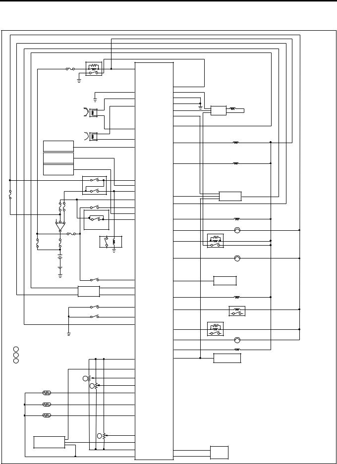
Circuit diagram
ECM wiring diagram (1)
|
|
|
D24 |
|
|
|
|
|
|
Main Relay |
|
|
|
|
|
|
|
|
D13 |
|
D9 |
|
|
|
|
|
|
D16 |
|
|
|
|
|
|
B6 |
|
D26 |
|
|
|
Pump Cam Position Sensor |
B5 |
|
A11 |
Spill Valve |
|
|
|
|
D20 |
|
||||
|
|
|
EDU |
|
|||
|
|
|
|
|
|
||
|
|
|
|
|
A15 |
|
|
|
|
|
|
|
|
|
|
|
Crankshaft Position Sensor |
B12 |
|
D6 |
|
|
|
|
|
|
|
|
|||
|
|
|
|
|
|
||
|
|
|
B11 |
|
D12 |
Timing Control Valve |
|
|
Vehicle Speed |
|
D7 |
|
|
|
|
|
|
|
|
|
|
||
|
Sensor |
|
|
|
|
|
|
|
Cooler |
|
|
|
|
EGR EVRV |
|
|
Compressor |
|
|
|
A1 |
|
|
|
|
|
|
|
|
|
|
|
Freezer |
|
|
|
|
|
|
|
Compressor |
Neutral SW |
A17 |
|
|
|
|
|
|
|
|
|
|
||
|
|
|
|
|
|
|
|
|
|
|
A20 |
|
|
|
|
|
|
|
A2 |
|
B3 |
|
|
|
|
Inhibitor SW |
A3 |
|
TCM |
|
|
|
|
|
B9 |
|
|||
|
|
Exhaust Brake SW |
A21 |
|
|
|
|
|
|
|
|
|
|
||
|
|
(A/T) |
A19 |
|
|
Swirl Control |
|
|
|
A6 |
|
A22 |
VSV |
|
|
|
|
|
|
|
|||
|
Key SW |
Clutch SW |
|
|
D21 |
Check Engine Lamp |
|
|
(M/T) |
|
|
|
|
||
|
|
|
|
|
D10 |
|
|
|
|
Starter Relay |
|
|
D22 |
Spill Valve Relay |
|
|
|
|
|
|
|
||
|
|
|
|
|
|
Glow Lamp |
|
|
|
Warm-Up SW |
B2 |
|
A13 |
|
|
|
|
|
|
TECH 2 |
|
||
|
|
|
A16 |
|
|
|
|
|
|
ABS/ASR |
|
|
|
|
|
|
|
B8 |
ECM |
|
Exhaust Brake VSV1 |
||
|
|
ECU |
D4 |
||||
|
|
|
|
|
|
||
|
|
Diagnostic SW |
A9 |
|
D23 |
Glow Relay |
|
|
|
|
|
|
|
||
|
|
Idle SW |
|
|
|
|
|
|
|
A10 |
|
|
|
|
|
|
|
|
|
|
Stop Lamp Relay |
|
|
|
|
|
A5 |
|
|
|
|
|
|
|
|
B7 |
|
|
|
|
|
|
|
|
|
|
|
|
|
|
|
|
D19 |
Exhaust Brake Lamp |
|
|
|
|
|
|
|
|
|
1 |
Accelerator Position Sensor |
|
|
|
A12 |
Intake VSV |
|
|
|
|
|
|
|
||
2 |
Idle Up Volume |
|
C3 |
|
B10 |
Tachometer |
|
5 |
PTO Position Sensor |
|
|
|
|
|
|
|
|
|
|
|
|
||
|
|
|
C4 |
|
|
|
|
|
|
|
C11 |
|
|
ECM |
: Engine Control Module |
|
|
1 |
|
|
|
|
|
|
|
C10 |
|
|
EDU |
: Engine Driver Unit |
|
|
Coolant Temperature |
2 |
|
|
|||
|
|
|
|
|
|
||
|
Sensor |
C1 |
|
|
|
|
|
|
|
|
|
EVRV: Electric Vacuum Regulating Valve |
|||
|
|
|
|
|
|||
|
Fuel Temperature |
|
|
|
|
||
|
|
|
|
|
|
|
|
|
Sensor |
|
C12 |
|
|
TCM |
: Transmission Control Module |
|
Intake Air Temperature |
|
|
|
|
VSV |
: Vacuum Switching Valve |
|
Sensor |
|
C15 |
|
|
||
|
|
|
|
|
|
||
|
|
5 |
C14 |
|
|
|
|
|
Intake Air |
C9 |
|
|
|
|
|
|
|
|
|
|
|
||
|
Pressure Sensor |
|
C6 |
|
D3 |
|
|
|
|
|
|
Pump |
|
||
|
|
|
C5 |
|
D17 |
|
|
|
|
|
|
ROM |
LNW21AXF000301-X |
||
|
|
|
|
|
|
||
1A-26 Engine Control System
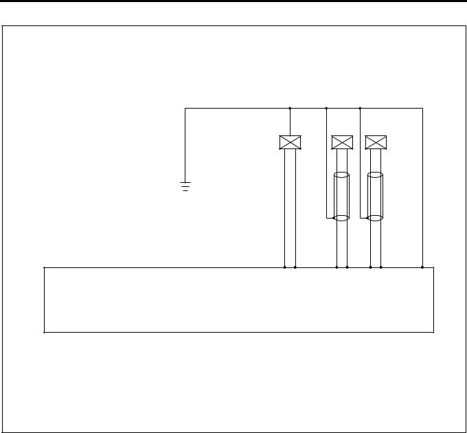
ECM Wiring Diagram (2)
1.25 B/L |
|
|
|
|
|
|
|
|
CKP |
|
NE |
|
|
|
ROM |
Sensor |
Sensor |
|
||
0.5 |
0.5 |
0.5 |
0.5 0.5 |
0.5 |
|
|
G/B |
G/R |
W |
R |
G |
L |
|
D17D3 |
B5B11 |
B6B12 |
D13 |
|||
|
|
(+) () |
(+) () |
|
||
Engine Control Module (ECM) |
|
|
|
|
|
|
Compensation ROM and NE Sensor are built in the Injection Pump |
|
|
|
|||
|
|
|
|
|
|
LNW21ALF000701-X |
Engine Control System 1A-27
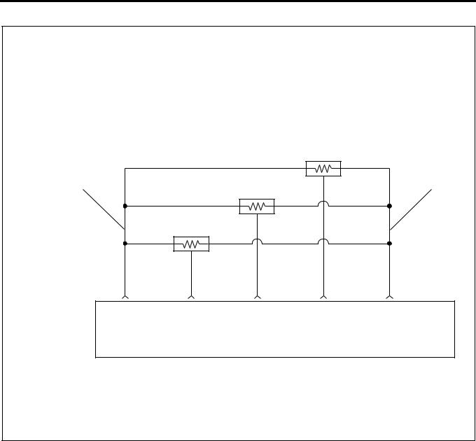
ECM Wiring Diagram (3)
|
|
|
AP (Accelerator Position) Sensor |
||
2 |
|
|
|
|
1 |
|
|
|
Idle Up Volume |
|
|
|
|
PTO Accelerator Sensor |
|
|
|
|
0.5 |
0.5 |
0.5 |
0.5 |
0.5 |
|
Y/B |
R/B |
Y/G |
G/O |
Y/R |
Engine Control Module |
C6 |
C14 |
C10 |
C11 |
C3 |
(ECM) |
(Sensor |
Signal |
Signal |
Signal |
(Sensor |
|
Ground) |
|
|
|
Power) |
|
|
|
|
|
LNW21ALF000501-X |
Characteristics of Circuit
•Multiple DTC is generated when several troubles (failures) occur. When multiple sensors or switches share a ground, or an open wiring or short occurs on the share power supply or ground, DTCs with respect to related sensors or switches are displayed.
If several DTCs are displayed, it is necessary to inspect the shared power supply or ground for open wiring or short.
The harness 1 shown above figure is the power common to the AP sensor and idle up volume, and the harness 2 is a common ground. In the event of open wiring in wire 1 or 2, DTC 24 and 31 are displayed at the same time. Like this, the case where two or more DTC’s are displayed is the multiple DTC.
•If multiple DTC24 and 31 are displayed, the power supply wire 1 or ground wire 2 must be checked.
DTC |
Sensor actuator (detection item) |
||
|
|
|
|
24 |
Accelerator position |
Connector not |
|
|
sensor |
connected, |
|
|
|
harness open wiring, |
|
31 |
idle up volume |
||
or |
|||
|
|
||
|
|
short, failure of |
|
|
|
main unit |
|
|
|
|
|
1A-28 Engine Control System
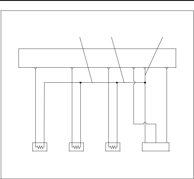
ECM wiring diagram (4)
|
|
|
3 |
2 |
|
|
1 |
ECM |
|
|
|
|
|
Sensor |
|
|
|
|
|
|
|
Ground |
|
C-1 |
|
C-12 |
C-15 |
C-9 |
C-5 |
C-4 |
|
|
|
|
|
|
0.5 |
0.5 |
0.5 |
|
|
|
|
|
Y/G |
W/ |
L/W |
|
|
|
|
|
|
GRN |
|
0.3 |
0.5 |
0.3 |
0.5 |
0.3 |
0.5 |
|
|
BLU/ |
W/ |
R/G |
W/ |
R/Y |
W/ |
|
|
RED GRN |
|
GRN |
GRN |
|
|
||
SIG |
GND |
SIG |
GND |
SIG |
GND |
|
|
Engine Coolant |
Fuel Temperature |
Intake Air |
Intake Air |
|
|||
Temperature |
Sensor |
Temperature |
Pressure Sensor |
||||
Sensor |
|
|
Sensor |
|
|
||
|
|
|
|
|
|
|
LNW21ALF000601-X |
Characteristics of Circuit
•Multiple DTC is generated when several troubles (failures) occur. When multiple sensors or switches share a ground, or an open wiring or short occurs on the share power supply or ground, DTCs with respect to related sensors or switches are displayed.
If several DTCs are displayed, it is necessary to inspect the shared power supply or ground for open wiring or short.
The harness 1 in above figure is a common ground for the engine coolant temperature sensor, fuel temperature sensor, intake air temperature sensor and intake air pressure sensor. In the event of the open wiring in the wire 1, DTC 21, 23, 41 and 32 are displayed at the same time. In the event of the open wiring in the wire 2, DTC 21, 23, and 41 are displayed at the time. Like this, the case where two or more DTC’s are displayed is the multiple DTC.
•If multiple DTC21, 23, 41, and 32 are displayed, the ground wire 1 must be checked.
•If multiple DTC21, 23, and 41 are displayed, the ground wire 2 must be checked.
•If multiple DTC21 and 23 are displayed, the ground wire 3 must be checked.
DTC |
Sensor actuator (detection item) |
||
|
|
|
|
21 |
Engine coolant |
|
|
|
temperature sensor |
Connector not |
|
|
|
connected, |
|
23 |
Intake air temperature |
||
|
sensor |
open wiring or |
|
|
|
short of harness, |
|
41 |
Fuel temperature sensor |
||
failure of |
|||
|
|
main unit |
|
32 |
Intake air pressure |
||
|
sensor |
|
|
|
|
|
|
Loading...