


4HL1
Table of contents
 Loading...
WORKSHOP MANUAL
727 (N SERIES)
ENGINE CONTROL SYSTEM
(4HL1 ENGINE)
SECTION 1A
International Service & Parts
Tokyo, Japan

N O T I C E
Before using this Workshop Manual to assist you in performing
vehicle service and maintenance operations, it is recommended
that you carefully read and thoroughly understand the information
contained in Section - 0A under the headings “GENERAL REPAIR
INSTRUCTIONS” and “HOW TO USE THIS MANUAL”.
All material contained in this Manual is based on the latest product
information available at the time of publication.
All rights are reserved to make changes at any time without prior
notice.

Engine Control System 1A-1
ENGINE
Engine Control System
CONTENTS
Engine Control System . . . . . . . . . . . . . . . . . . . . 1A-2
Precautions on Service . . . . . . . . . . . . . . . . . . 1A-2
Function and Operation . . . . . . . . . . . . . . . . . . 1A-3
Powertrain System Components . . . . . . . . . . . 1A-9
Circuit Diagram . . . . . . . . . . . . . . . . . . . . . . . 1A-20
Strategy-Based Diagnostics . . . . . . . . . . . . . . 1A-38
Functional Check List . . . . . . . . . . . . . . . . . . . 1A-44
Hearing Diagnostic . . . . . . . . . . . . . . . . . . . . . 1A-44
On-Board Diagnostic (OBD) System Check . 1A-47
Inactive CHECK ENGINE Lamp Check . . . . . 1A-50
Unblinking CHECK ENGINE Lamp Check . . . 1A-54
ECM Power Supply and Grounding System Circuit
Check . . . . . . . . . . . . . . . . . . . . . . . . . . . . . . . 1A-56
Diagnosis with Tech 2 Scan Tool . . . . . . . . . . 1A-59
Diagnostic Chart . . . . . . . . . . . . . . . . . . . . . . . 1A-88
DTC14 - CMP Sensor System Fault . . . . . . . 1A-93
DTC15 - CKP Sensor System Fault . . . . . . . . 1A-97
DTC18 - Starter Degradation (For Only Vehicles
Equipped with Idle Stop Function) . . . . . . . . 1A-101
DTC22 - IAT Sensor System Fault . . . . . . . . 1A-103
DTC23 - ECT Sensor System Fault . . . . . . . 1A-107
DTC24 - Accelerator Sensor System Fault . 1A-112
DTC25 - Vehicle Speed Sensor System
Fault . . . . . . . . . . . . . . . . . . . . . . . . . . . . . . . 1A-116
DTC28 - PTO Accelerator Sensor System
Fault . . . . . . . . . . . . . . . . . . . . . . . . . . . . . . . 1A-120
DTC31 - Idle Up Volume System Fault . . . . 1A-123
DTC33 - VIM Internal Fault (EEPROM Write
Error) . . . . . . . . . . . . . . . . . . . . . . . . . . . . . . 1A-127
DTC34 - ECM Internal Fault (Charge Circuit
Fault) . . . . . . . . . . . . . . . . . . . . . . . . . . . . . . 1A-129
DTC35 - VIM Internal Fault (A/D Conversion
Fault) . . . . . . . . . . . . . . . . . . . . . . . . . . . . . . 1A-132
DTC43 - ITP Sensor System Fault . . . . . . . . 1A-134
DTC44 - EGR Valve Position Sensor System
Fault . . . . . . . . . . . . . . . . . . . . . . . . . . . . . . . 1A-139
DTC45 - EGR Valve System Fault . . . . . . . . 1A-144
DTC46 - Exhaust Brake System Fault . . . . . 1A-147
DTC51 - ECM Internal Fault (CPU Error / CPU
History Error) . . . . . . . . . . . . . . . . . . . . . . . . 1A-150
DTC52 - ECM Internal Fault
(Sub CPU Error) . . . . . . . . . . . . . . . . . . . . . . 1A-152
DTC61 - Intake Throttle Valve System Fault 1A-154
DTC71 - Barometric Pressure Sensor Fault 1A-157
DTC81 - Clutch Switch System Fault . . . . . . 1A-159
DTC82 - Neutral Switch System Fault . . . . . 1A-163
DTC84 - CAN Communication Fault
(CAN Bus Error) . . . . . . . . . . . . . . . . . . . . . . 1A-166
DTC86 - CAN Communication Fault
(CAN Timeout Error) . . . . . . . . . . . . . . . . . . . 1A-169
DTC115 - Common Rail Pressure Sensor Fixed
Output Fault . . . . . . . . . . . . . . . . . . . . . . . . . 1A-172
DTC1 18 - Common Rail Pressure Fault
(Control System) . . . . . . . . . . . . . . . . . . . . . 1A-177
DTC158 - Injector Power Supply System Short
(Common 1) . . . . . . . . . . . . . . . . . . . . . . . . . 1A-182
DTC159 - Injector Power Supply System Short
(Common 2) . . . . . . . . . . . . . . . . . . . . . . . . . 1A-186
DTC21 1 - Fuel Temperature Sensor System
Fault . . . . . . . . . . . . . . . . . . . . . . . . . . . . . . . 1A-190
DTC217 - SCV Drive System Short . . . . . . . 1A-195
DTC227 - No Pump Pressure Feed (Fuel Leak)
. . . . . . . . . . . . . . . . . . . . . . . . . . . . . . . . . . . 1A-198
DTC241 - Idle Position Switch Circuit Open
Wiring . . . . . . . . . . . . . . . . . . . . . . . . . . . . . . 1A-203
DTC242 - Idle Position Switch Circuit Short . 1A-206
DTC245 - Common Rail Pressure Sensor
System Fault . . . . . . . . . . . . . . . . . . . . . . . . 1A-209
DTC247 - SCV Drive System Fault . . . . . . . 1A-215
DTC271 - Cylinder 1 (Injector Drive System)
Fault . . . . . . . . . . . . . . . . . . . . . . . . . . . . . . . 1A-219
DTC272 - Cylinder 2 (Injector Drive System)
Fault . . . . . . . . . . . . . . . . . . . . . . . . . . . . . . . 1A-223
DTC273 - Cylinder 3 (Injector Drive System)
Fault . . . . . . . . . . . . . . . . . . . . . . . . . . . . . . . 1A-227
DTC274 - Cylinder 4 (Injector Drive System)
Fault . . . . . . . . . . . . . . . . . . . . . . . . . . . . . . . 1A-231
DTC277 - Injector Power Supply System Open
Wiring Fault (Common 1) . . . . . . . . . . . . . . . 1A-235
DTC278 - Injector Power Supply System Open
Wiring Fault (Common 2) . . . . . . . . . . . . . . . 1A-239
DTC416 - Main Relay System Fault . . . . . . . 1A-243
DTC417 - Starter Switch System Fault . . . . 1A-246
DTC543 - High Engine Speed Error . . . . . . . 1A-249
Default Matrix Table . . . . . . . . . . . . . . . . . . . 1A-250
Special Tools . . . . . . . . . . . . . . . . . . . . . . . . 1A-256
Wiring Harness Repair: Shielded Cable . . . . . 1A-257
Removal Procedure . . . . . . . . . . . . . . . . . . . 1A-257
Installation Procedure . . . . . . . . . . . . . . . . . 1A-257
Twisted Leads . . . . . . . . . . . . . . . . . . . . . . . . . 1A-258
Removal Procedure . . . . . . . . . . . . . . . . . . . 1A-258
Installation Procedure . . . . . . . . . . . . . . . . . 1A-258
Weather-Pack Connector . . . . . . . . . . . . . . . . 1A-260
Removal Procedure . . . . . . . . . . . . . . . . . . . 1A-260
Installation Procedure . . . . . . . . . . . . . . . . . 1A-260
Special Tools . . . . . . . . . . . . . . . . . . . . . . . . 1A-261
Com-Pack III . . . . . . . . . . . . . . . . . . . . . . . . . . 1A-262
General Information . . . . . . . . . . . . . . . . . . . 1A-262
Metri-Pack . . . . . . . . . . . . . . . . . . . . . . . . . . . . 1A-263
Removal Procedure . . . . . . . . . . . . . . . . . . . 1A-263
Installation Procedure . . . . . . . . . . . . . . . . . 1A-263
Special Tools . . . . . . . . . . . . . . . . . . . . . . . . 1A-263

1A-2 Engine Control System
ngine Control System
E
Precautions on Servic e
Circuit test tools
Unless otherwise specified in diagnostic procedures,
do not use Test Light to diagnose the powertrain
electrical system. When diagnostic procedures need
probe connector, use Connector Test Adapter Kit 58840-0385-0.
On-market electrical equipment and vacuum
devices
On-market electrical equipment and vacuum devices
refer to those components that will be installed to
vehicles after shipme nt from manufacturing plants. Be
careful that installation of these components is not
considered during the process of vehicle design.
CAUTION:
Do not install on-market vacuum devices to
vehicles.
CAUTION:
Connect on-market electrical equipment, as well as
its power supplies and grounds, to the circuits
isolated from the electronic control system.
The on-market electrical equipment, even when
installed to vehicles in normal manner, may bring
functional troubles to the electronic control system.
Affected devices include those not connected to the
vehicle electrical equipment system, for example,
mobile phones or radios. Therefore, when you intend to
diagnose the powertrain, check such the on-market
electrical equipment has not been installed to the
vehicle and, if installed, remove it. If faults still occur
even after removal of on-market electric al equipment,
diagnose the vehicle according to normal procedures.
Damage by electrostatic discharge
Electronic components used in the electronic control
system are designed to w ork at very low volta ges and,
for this reason, they are susceptible to damage by
electrostatic discharge and some types of electronic
components may be damaged even by the static
electricity of less th an 100 V that is us ually not sensed
by persons. Persons’ sensitivity level is 4,000 V.
Persons are electrostatically charged in various ways
and the most typical e lectrification sources are f riction
and induction. Shown below are examples.
• Electrification by friction occurs when a person
slides on the seat in the vehicle.
• Electrification by induction occurs when a person
with insulating shoes is standing near a highly
electrifiable substance and touches a ground
momentarily. Electric charges with the same
polarity flow out and resultantly the person is
charged at high opposite polarity. Since static
electric charges cause damages, it is important
when you handle or test electronic components.
CAUTION:
To prevent damages by electrostatic discharge,
follow the guidelines shown below.
• Do not touch ECM connector pins as well as
electronic components soldered to the ECM
circuit board.
• Do not unpack each replacement component
until preparations are completed for the
component.
• Before taking out a component from the
package, connect the package to the normal
grounding line of the vehicle.
• When you intend to slide on the seat, change
the posture from standing to sitting, or wa lk by
a certain distance to handle a component,
touch an appropriate grounding material.
Wire color
All wiring harnesses are id entifi ed using colored jac ket.
The wiring harness used for the main circuit in an
electrical system is identifi ed with sing le color while t he
wiring harness used for the sub- circu it is i dentif ied with
color stripe. The following rule is used in each wiring
diagram to indicate size and color of a wiring harness.
eg. : 0.5 GRN / RED
1
2
3
LNW21ASH000101-X
Legend
1. Red (stripe color)
2. Green (base color)
3. Harness size (0.5 mm
2
)

Engine Control System 1A-3
Symbol Color Symbol Color
BBlackBRBrown
W White LG Light green
R Red GR Gray
GGreenP Pink
Y Yellow LB Light blue
L Blue V Violet
OOrange
Function and Operation
Electronic Control System
The electronic control system processes the data,
which has been collected with various types of sensors,
by means of the control program installed to ECM
(engine control module) to totally control engine
parameters such as fuel injection quantity, injection
timing, engine startup, altitude compensation, and
EGR.
ECM
ECM Description
The ECM is mounted in th e inner part of the engine lef t
side cover. The ECM monitors variou s data sent from
diversified sensors and controls systems in the
powertrain. The ECM diagnoses these systems to
detect faults with respect to system operations and
inform the driver of faulty condition via the CHECK
ENGINE lamp (MIL) and stores DTCs (diagnostic
trouble codes). DTC identifies the trouble generation
area to aid repairs by service operators.
Function of ECM
ECM supplies 5 V and 12 V voltages to various sensors
and switches. Since powers are supplied via high
resistances in EC M, Test Light, even when c onnected
to the circuit, will not be lit. In a special case, a no rmal
voltmeter does not indicate correct values since the
resistance of the ins trument i s too low. To get a ccurate
readings, you need a digital voltmeter whose input
impedance is at least 10 MΩ. The special tool 5-88400366-0 is a proper choice for this measurement. In the
ECM, the output c ircuit is controlled by regulati ng the
grounding system or power circuit via transistor or
either of the devices listed below.
• Output driver module (ODM)
• Quad drive module (QDM)
ECM and Components
The ECM is designed to offer excellent drivability and
fuel economy while achieving exhaust gas emission
control requirements. The ECM monitors engine and
vehicle functions via various electronic sensors such as
CKP (crank position) and VS (vehicle speed) sensors.
Voltages from ECM
The ECM supplies reference voltages to various
switches and sensors. Resistances of the ECM are
very high and this allows the ECM to supply voltages to
these devices, and v oltages actually app lied to circuits
are low and even connecting Test Light to individual
circuits may fail turn-on. Since the voltmeter normally
used in service factories has low input impedance,
correct readings m ay not be obtain ed. To get accurate
readings, a digital voltmet er whose input impedanc e is
10 MΩ (for example, 5-8840-0366-0) should be used.
Input/output devices of the ECM include analog-todigital converter, signal buffer, counter, and special
driver. By using electronic switch es, the ECM controls
most system components and turning off a switch
closes the ground circuit. These switches are divided
into four-switch or seve n- sw itc h gr ou ps, a nd th e former
group is called qu ad driv er mo dul e (Q DM) and controls
up to four output pins respectively while the latter group
is called output driver module (ODM) and controls up to
seven outputs respectively. Note that all the outputs are
necessarily not used in the control.
Electrically Erasable Programmable ROM
(EEPROM)
EEPROM is a permanent memory chip and soldered to
the board in the ECM. EEPROM stores program and
calibration data, both of which are necessary for the
ECM to control the powertrain. Different from
conventional ROMs, EEPROM cannot be replaced with
new component. If EEP ROM fails, the complete ECM
assembly must be replaced with new one.
Precautions on ECM Servic e
The ECM is designed to withstand ordinary currents
used in operations of a vehicle. Be careful that the
circuits must not be overloaded. To test the ECM to
check open wiring or short, ECM circuits must be
connected to the ground or voltages must not be
applied to the ECM. To test ECM circuits, the digital
voltmeter 5-8840-0366-0 should always be used.
1A-4 Engine Control System
Engine Control System
Accelerator
AP sensor
Idle position switch
Switch
A/C switch
Relay/Lamp
Starter cut relay
Glow relay
Check engine lamp
Common rail
Common rail
Injector
Exhaust
pipe
EGR cooler
pressure sensor
SCV
Supply
pump
EGR valve drive
EGR valve position sensor
CMP sensor
ITP sensor
Intake throttle drive
ECT
FT sensor
ECM
(Engine Control Module)
IAT sensor
CAN
Starter
Ignition switch
Starter switch
Battery
Outer diagnostic unit
Diagnostic switch
Main relay
Battery +
Atomospheric
pressure sensor
VIM
(Vehicle Interface Module)
Vehicle functions
Tachometer
TCM
ABS/ASR ECU
ISS ECU
Relay
ECO Relay,
Exhaust Brake
Lamp
Exhaust Brake Lamp
Glow Lamp
Brake
Stop Lamp Relay
Exhaust Brake Lamp
Transmission
Clutch Switch
Neutral Switch (MT)
Parking
/Neutral (AT)
Switch
Vehicle Speed Sensor
Power Take OFF (PTO)
PTO Switch (
ACTIVE HIGH
ACTIVE LOW
PTO Switch (
PTO Accelerator Sensor
Quick Warm Up System
QWS Switch
Idle
Idle Up Volume
Others
Freezer Switch
Clean Starting Memory
)
)
CKP
Exhaust brake
solenoid valve
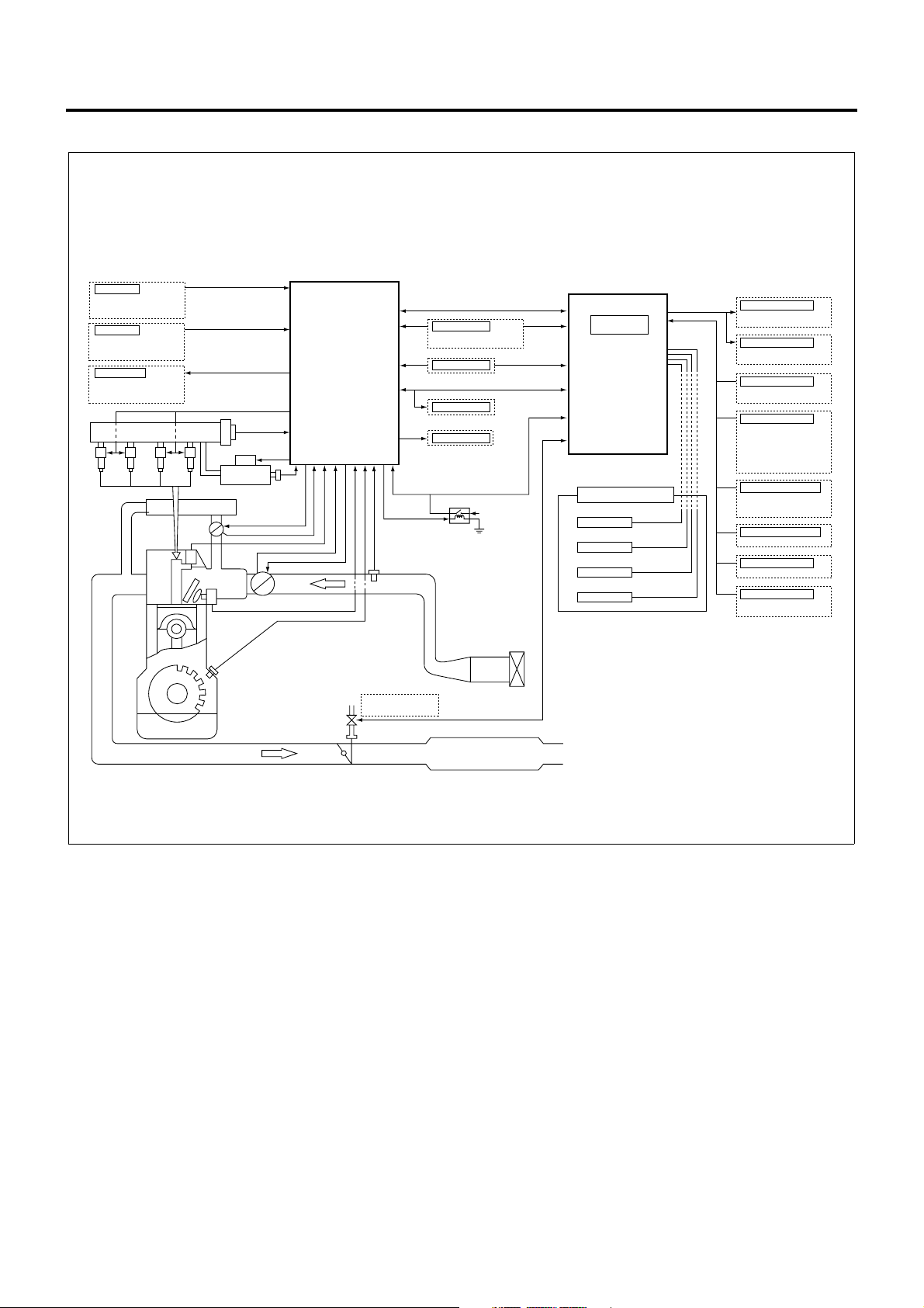
The engine control system comprehends vehicle status
and driver’s i ntention based on the data acquired from
sensors and switches to adapt the engine to chang ing
situation so that the vehicle will achieve optimal running
condition. The heart of the engine control system is
ECM and this device provides direct control tasks for
the engine system, including fuel injection control,
intake throttle control , EGR control, and QWS control.
The ECM also governs vehicle system control
strategies such as ex haust brake control and id le stop
control via VIM. In addition, the ECM communicates
with other key systems, including ABS/ASR system
and clutch free system, via VIM.
LNW21ALF004601-X
Fuel Injection Control
Engine Control System 1A-5
DTC Detection Status
Battery Voltage
Key Switch Position
Engine Speed
Vehicle Speed
Engine Coolant Temp.
Intake Air Temp.
Fuel Temp.
Common Rail Pressure
Accelerator Pedal Position
Idle Position Switch
Clutch Switch
Neutral Switch
PTO Switch
Idle Stop
Status Judge
Compensation
Desired Injection
Quantity
Determine
ECM
Compensation
Injector
Energize Time/
Timing Determine
Compensation
SCV Position
Determine
Injector
Control
SCV
Control
LNW21AMF005601-X
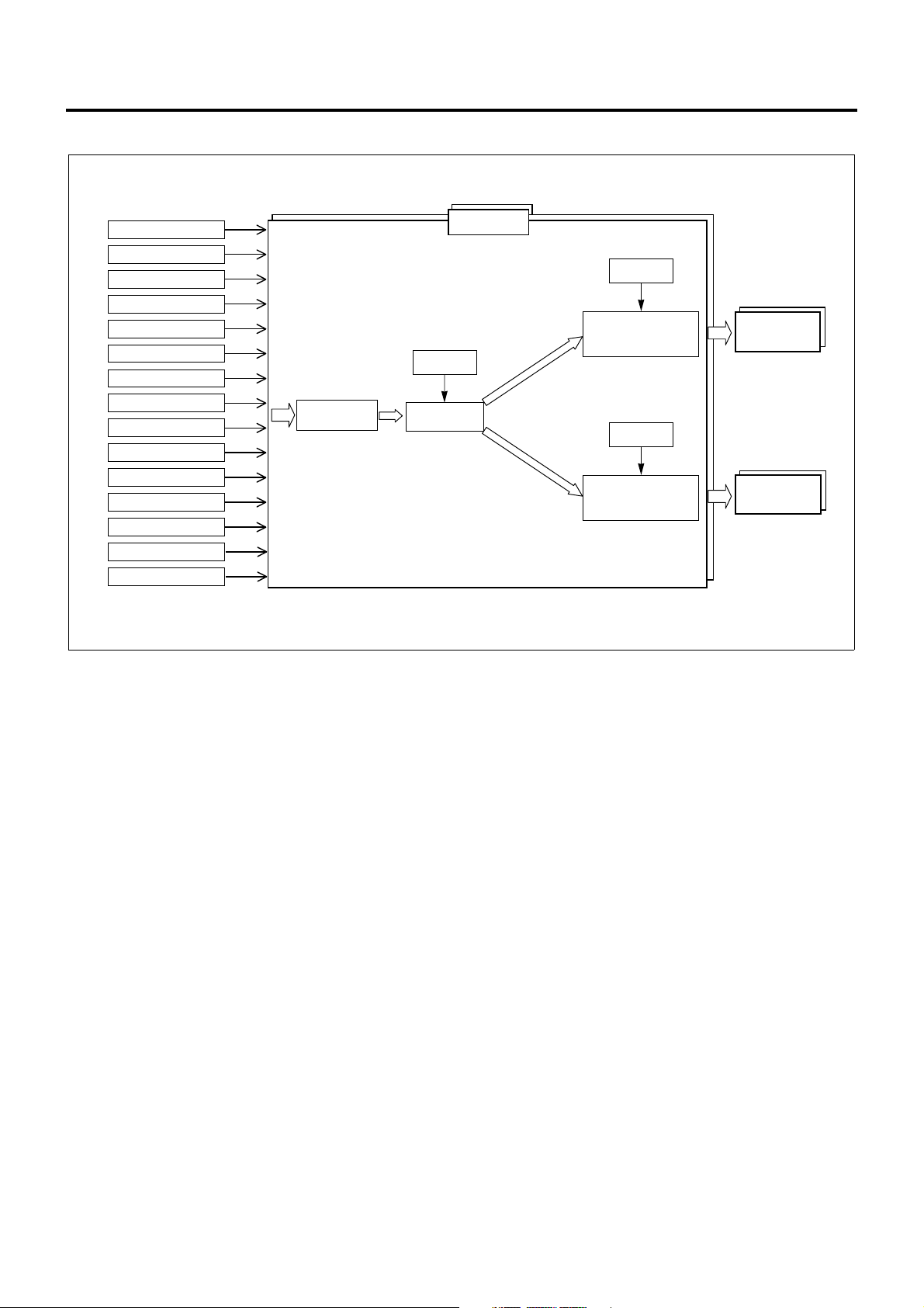
The fuel injecti on con t rol system manages the i nje ct ion
quantity, injection timing, and injection pressure
according to the status of vehicle. This system changes
the injection quantity using injector operating period,
the injection timing using injector operation timi ng, and
the injection pressure using SCV drive duty,
respectively. The fuel injection co nsists of two stages,
pilot injection and main injection, and the control
system changes the amount and timing in individual
stages according to the conditions encountered.
The ECM uses the data acquired from associated
sensors and switches to judge the current vehicle
status, i.e., startup, idling, PTO, or idle stop, and
calculate the desired injection quantity. Once the
desired injection quantity is determined, ECM
calibrates the value to determine injector energize time,
energize timing, and SCV opening and controls
injectors and the SCV accordingly.
Calculation of Desired Injection Quantity
The ECM calcu lates the basic injecti on quantity using
engine speed, accelerator pedal position, engine
coolant temperature, a nd other necessary parameters
and calibrates this value based on the atmospheric
pressure or the li ke to determine the desire d injection
quantity.
Injector Control
The injector control consists of four stages: "control
stop mode" where the fuel injection is completely
stopped, "split injection mode" where two (or more)
injection shots are mad e for one cylinder at low engine
speeds and temperatures, "fixed injection mode" where
only main injectio n is made at ve ry low engine sp eeds
during startup, and "normal in jection mode" where the
fuel injection is made within normal engine speed
range. The proper mo de is selecte d according to s uch
the parameters as engine speed, engine coolant
temperature, and DTC. The ECM uses the desired
injection quantity, intake air temperature, engine
coolant temperature, and other parameters to
determine injector energize period (desired injection
period) and injector energize timing (desired injection
timing) and control i njectors according to the injec tion
mode selected.
SCV Control (Pump Control)
Pumps are controlled in six stages: "shutoff mode",
"start mode", "wait mode", "restart mode", "feedback
mode", and "deflate mode". The proper mode is
selected according to such the parameters as key
switch position, common rail pressure, and engine
speed. The ECM calcu lates desired injecti on pressure
and pump flow rate for the selected mode based on
intake air temperature, engine coolant temperature,
engine speed, desired injection quantity, and other
necessary parameters. Then , the ECM determines the
SCV opening (SCV drive duty) us ing thes e result s and
controls the SCV.
1A-6 Engine Control System
Intake Throttle Control
3
1
2
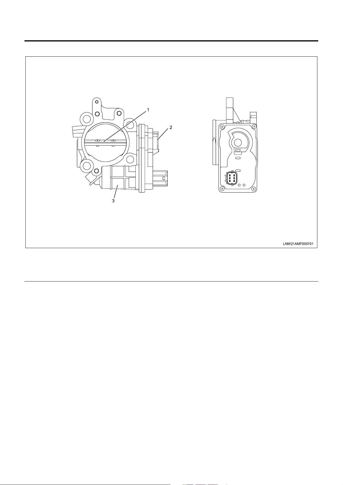
Legend
1. Intake throttle valve
2. ITP (intake throttle position) sensor
The intake throttle control system changes (throttles)
the air according to the vehicle status and reduces
suction noises generated from the working exhaust
brake and acceleration. This control is made by
opening and closing the intake throttle valve. The
intake throttle valve is ope rated by the DC motor and
changing the drive voltage (duty: see Note 1) opens
and closes the v alve. The intake throttle valve i s fully
opened in the normal state (i.e., the DC motor is
inactive) and gradually reduces the opening as the
drive voltage is increased. The ECM uses the ITP
(intake throttle position) sensor to detect the working
condition of the intake throttle valve. When the valve
opening gets smaller (the drive voltage is increased),
the output voltage of the ITP sensor becomes lower.
The valve position is norm ally calculated using engine
coolant temperature, engine speed, and desired
injection quantity, and the DC motor drive voltage is
determined from this calculated value. However, the
ECM completely opens the throttle valve when the
vehicle is in idle stop, DTC is set for the intak e throttle
system, AP sensor system, or EGR system, gear
shifting is perfo rmed (for m anual trans missi on ve hicle ),
the engine coolant temperature is low (less than 70°C),
or the vehicle is i n startup or en gine s tall sta tus wh ile i t
completely close s the valve immediately after the key
LNW21AMF005701
3. Intake throttle DC motor
switch is turned off (within 0.5 to 3.0 seconds).
There is an opposing relationship between intake
throttle control and EGR control. When the intake
throttle valve is opened, the EGR valve is closed, and
vice versa.
Note 1: Duty (%) = Energize ratio
EGR Control
Engine Control System 1A-7
1
2
3
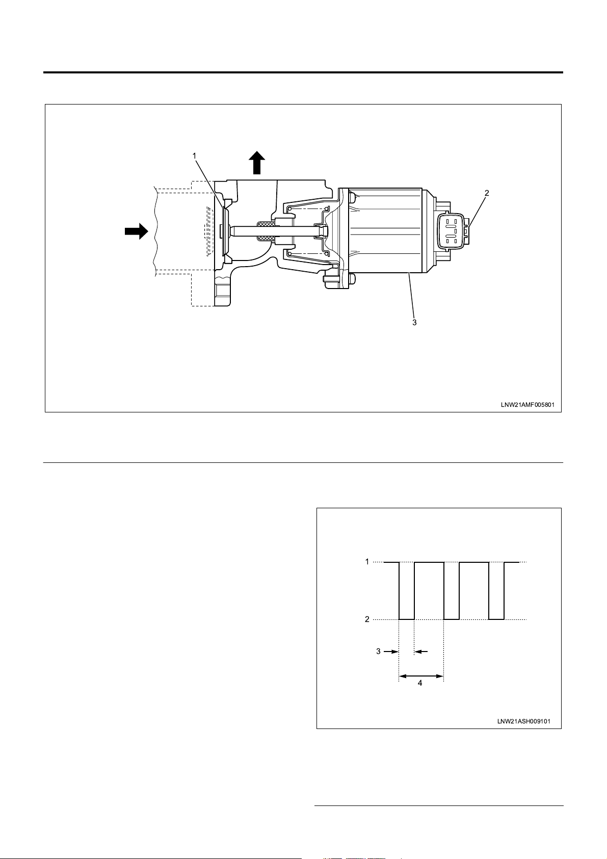
Legend
1. EGR valve
2. EGR valve position sensor
The EGR control system recirculates a portion of
exhaust gas to the intake to drop the combustion
temperature and thus reduce NOx. This control is
made by opening and closing the EGR valve. The EGR
valve is operated by the DC motor and changing the
duty (see Note 1) opens and closes the valve. This
EGR valve is f ully closed in the nor mal state (i.e., the
DC motor is inactive) and gradually enlarges the
opening as the duty is increased. The ECM uses the
EGR valve posit ion sens or to com prehend the working
condition of the EGR valve. When the valve opening
gets larger (the duty is increased), the output voltage of
the EGR valve position sensor becomes higher.
The EGR control is initiated when parameters such as
engine speed, engine coo lant temperatu re, acce lerator
position, atmospheric pressure, and system voltage
meet the required conditions, and the EGR valve
opening is calculated from engi ne c oolan t t emp eratur e ,
engine speed, and desire d inje ction quanti ty. The ECM
determines the drive duty of the DC motor based on
this valve position and drives the motor. The EGR
control is turned off when the exhaust brake is
operated, the PTO is working, the A P sensor fails, the
ECT sensor fails, the EGR system fails, or th e intake
throttle system fails.
There is an opposing relationship between EGR control
and intake throttle control. When the intake throttle
valve is opened, the EGR valve is closed, and vice
versa.
LNW21AMF005801
3. EGR DC motor
Note 1: Duty (%) = T (*) / 5 (msec) × 100
* T = Duty input time (see motor drive voltage
waveform)
1
2
3
4
LNW21ASH009101
Legend
1. 24V
2. 0V
3. T (duty input time)
4. 5 msec

1A-8 Engine Control System
QWS Control
The QWS (quick warm- up system) curtails the engine
warm-up time. The glow control covers the engine
warm-up during the period from pre-startup to
immediate completion of startup. The QWS works
when the vehicle meets the required conditions after
engine startup and the dr iv er tu rn s o n th e Q WS s wit ch ,
and lasts until the vehicle deviates from the QWS
working conditions.
QWS working conditions
• The engine coolant is less than 73°C.
• The engine is running at or above 40 0 rpm for at
least 0.5 second.
• Both EGR and PTO controls are disabled.
• The vehicle is free from AP sensor fault, ECT
sensor fault, A/D conversion fault, idle position
switch fault, clutch switch fault, neutral switch fault,
and vehicle speed sensor fault.
• The difference between actual and desired eng ine
speeds is less than 50 rpm.
• The desired engine speed is less than 1000 rpm.
• The vehicle is being off.
• The state where the starter switch is turned off and
the idle position switch is turned on lasts for at
least 0.5 seconds.
Exhaust Brake Control
A valve is instal le d ins id e t he exhaust pipe. Closing this
valve increases the resistance during the exhaust
stroke to enhance the effect of engin e brake. T he drive
source of the exhaust brake valve is vacuum. A
solenoid valve is inst alled to control the vacuum. The
exhaust brake is contr olled by o pening and clo sing this
solenoid electrically. When the engine is running at or
above 500 rpm, the e xhaust cut command is no t sent
from the automatic transmi ssion, and exhaust brake or
QWS working co nditions are completely me t, the VIM
turns on the solenoid valve.
• For a manual transmission vehicle, the clutch
pedal is not pressed. For an automatic
transmission veh icle, the exhaus t brake co mmand
is not sent from the automatic transmission.
• The system voltage stays between 20 V and 30 V .
Idle Stop Control (for Vehicles Equipped with Idle
Stop Control System)
The idle stop control system automatically cuts the
engine to prevent t he black smoke emission f rom the
vehicle that is not running for unloading or other works
(to restart the engine, manual operation is needed).
When all the idle stop conditions are met, the ECM
stops fuel injection and actuate s energy-saving relays
to turn off wipers, mirror defoggers, flashers, seat
heaters, and other electrical equipment.
Idle Stop Control Working Conditions
• The driver fails to apply the parking brak e and the
signal is input from the alarm unit. (Note 1)
• The vehicle ran at or above 5 km/h.
• The vehicle is idling.
• The vehicle speed is 0 km/h.
• The shift lever is in the neutral position.
• The QWS switch is turned off.
• The engine coolant temperature is at least 10°C.
• The battery voltage is at least 22 V.
• DTC has not been detected.
Note 1: When all the following conditions are met, the
parking brake disengagement alarm unit outputs the
idle stop permit signal to the VIM.
• The idle stop main switch is turned on.
• The shift lever is in the neutral position.
• The parking brake is applied.
• The headlamps are turned off.
• Any of doors is opened.
Exhaust Brake Working Conditions
• The vehicle is running at or abo ve 5 km/h or faults
are not detected on the vehicle speed sensor.
• The exhaust brake switch is turned on.
• The engine is running at or above 50 0 rpm for at
least 1 second.
• The idle position switch is turned on and the gear
is engaged.
• The vehicle is not eq uipped with ABS/ASR or the
exhaust brake cut command is not sent from the
ASR.
• The vehicle is free from AP sensor fault, exhaust
brake circuit fault, clutch switch fault, neutral
switch fault, idle position switch fault, A/D
conversion fault (VIM), and CAN timeout (VIM).
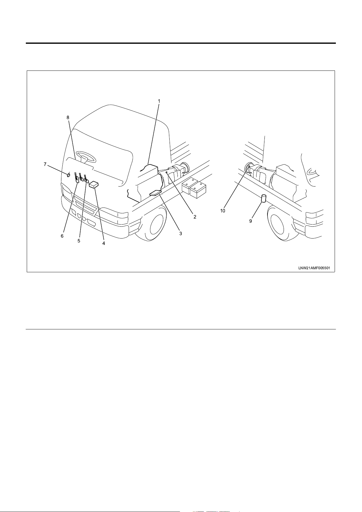
Powertrain System Components
Component Layout - Vehicle Side
8
7
Engine Control System 1A-9
1
6
5
4
Legend
1. Engine
2. Neutral switch
3. ECM (engine control module)
4. VIM (vehicle interface module)
5. Clutch pedal
2
10
3
6. Accelerator pedal
7. DLC (data link connector)
8. CHECK ENGINE lamp (MIL)
9. Exhaust brake solenoid valve
10. VS (vehicle speed) sensor
9
LNW21AMF005501
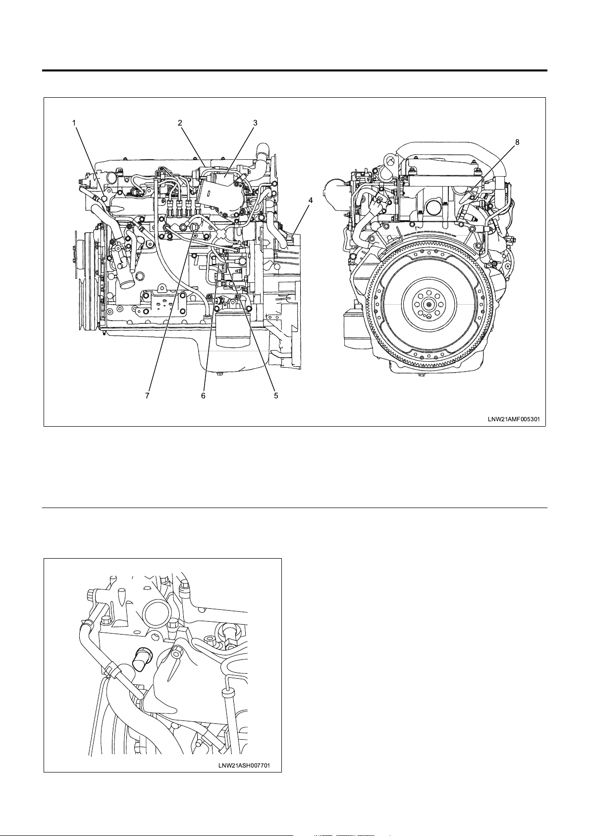
1A-10 Engine Control System
Component Layout - Engine Side
123
8
4
67
Legend
1. ECT (engine coolant temperature) sensor
2. EGR valve
3. Intake throttle valve
4. CKP (crank position) sensor
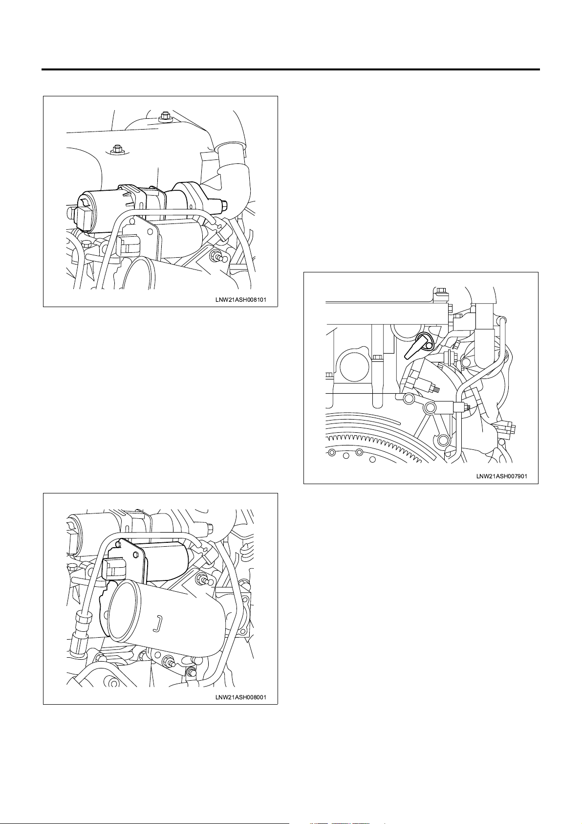
Function and Operation
ECT Sensor
5
LNW21AMF005301
5. FT (fuel temperature) sensor
6. SCV (suction control valve)
7. Common rail pressure sensor
8. CMP (cam position) sensor
The ECT (engine coolant temperature) sensor is
installed to the thermosta t housing and the thermistor
in the sensor alte rs the resistance in response to the
temperature change. The resistance is decreased
when the coolant temperat ure is high while increased
when the temperature is l ow. The ECM supplies 5 V to
the ECT sensor via pull-up resistance and calculates
the engine coolant temperature from the change in
voltage and uses it in fuel injection control, EGR
control, and other control tasks. This voltage is
decreased when the resistance is large (the
temperature is high) while increased when the
resistance is large (the temperature is low).
LNW21ASH007701
Engine Control System 1A-11
EGR Valve and EGR Valve Position Sensor
LNW21ASH008101
The EGR valve is installe d at the top of the inlet cov er
and operated by a DC motor. The DC motor operates
the EGR valve by changing the duty. The valve is
opened when the duty is inc reased while closed when
the duty is decreased. T he ECM c alculate s the desir ed
EGR valve opening based on the vehicle running
condition and controls the DC motor accordingly.
The EGR valve po sition senso r is installed to the EGR
valve and sends the voltage signal that w ill change in
response to the EGR va lve opening to the ECM. The
ECM calculates the desired EGR valve opening from
the voltage signal and uses the result in EGR control.
The intake throttle valve is installed to the intake throttle
and operated by a DC motor. The DC motor operates
the intake throttle valv e by changing the drive voltage.
The valve is closed when the drive voltage is increased
while opened when the voltage is decreased. The ECM
calculates the intake throttle valve opening based on
the vehicle running condition and controls the DC
motor accordingly.
The ITP (intake throttle pos ition) sensor is installed to
the intake throttle valve and sends the voltage signal
that will change in response to the throttle valve
opening to the ECM. The E CM calculates the throttle
valve opening from the voltage signal and uses the
result in intake throttle control.
CMP Sensor
Intake Throttle Valve and ITP Sensor
LNW21ASH007901
The CMP (cam position) sensor is installed to each
cylinder head and, when the hol e on the camsha ft gear
passes the sensor, a CMP signal is generated. The
ECM identifies the cylinder from the CMP signal as well
as CKP signal sent from the CKP sensor and
determines the cran k angl e, and u ses t his a ngle in fue l
injection control and engine speed calculation. These
tasks are usually perform ed based on the CKP signal
but if the CKP sensor fails, the CMP signal will
substitute for the CKP signal.
LNW21ASH008001
1A-12 Engine Control System
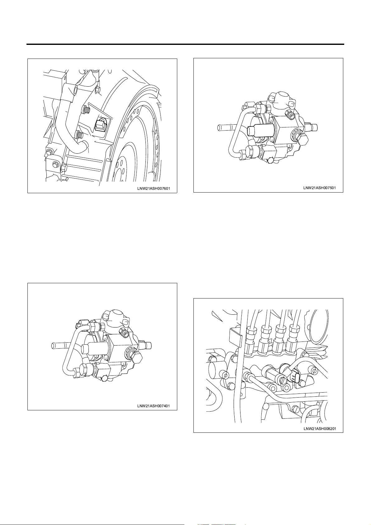
CKP Sensor
LNW21ASH007601
The CKP (crank position) sensor is installed to the
flywheel housing and, when flywheel teeth pass the
sensor, a CKP signal is generated. The ECM ident ifies
the cylinder from the CKP s ignal as well as the CMP
signal sent from the CMP sensor and determines the
crank angle, and uses this angle in fuel injection control
and engine spe ed calculati on. These t asks are usually
performed based on the CKP signal but if the CKP
sensor fails, the CMP signal will substitut e for the C KP
signal.
FT Sensor
SCV
LNW21ASH007501
The SCV (suction control valve) is installed to the
supply pump and controls the suction fuel quantity. The
SCV is fully opened in normal state and larger drive
voltage (duty) results in smaller opening. The ECM,
based on the data acquired from sensors, calculates
the desired common rai l pressure and pump flow rate
and compares the calculated desired common rail
pressure to the actual value to determine the SCV
opening. When the actual pressure is lower than the
desired value, the SCV is opened to increase the pump
flow rate. When the actual pr essure is higher than the
desired value, the SCV is closed to decre ase the flow
rate.
LNW21ASH007401
The FT (fuel temperature) sensor is installed to the
supply pump and the thermistor in the sensor alters the
resistance in res pon se to the te mpe ra tur e cha nge. The
resistance is decreased when the fuel temperature is
high while incr eased when the temper ature is low. The
ECM supplies 5 V to the FT sensor via pull-up
resistance and calculates the fuel temperature from the
change in voltage a nd uses it in supply pump control
and other control tasks. This voltage is decreased
when the resistance is smal l (the temperature is high)
while increased when the resistance is large (the
temperature is low).
Common Rail Pressure Sensor
LNW21ASH008201
The common rail pressure sensor is installed to the
supply pump, and detects the fuel pressure in the
common rail, converts the pressure into a voltage
signal, and sends the signal to the ECM. Higher
common rail pressure provides higher voltage while
lower pressure provides lower voltage. The ECM
calculates actual common rai l pressure (f uel pressure)
from the voltage signal and uses the result in fuel
injection control and other control tasks.
Engine Control System 1A-13
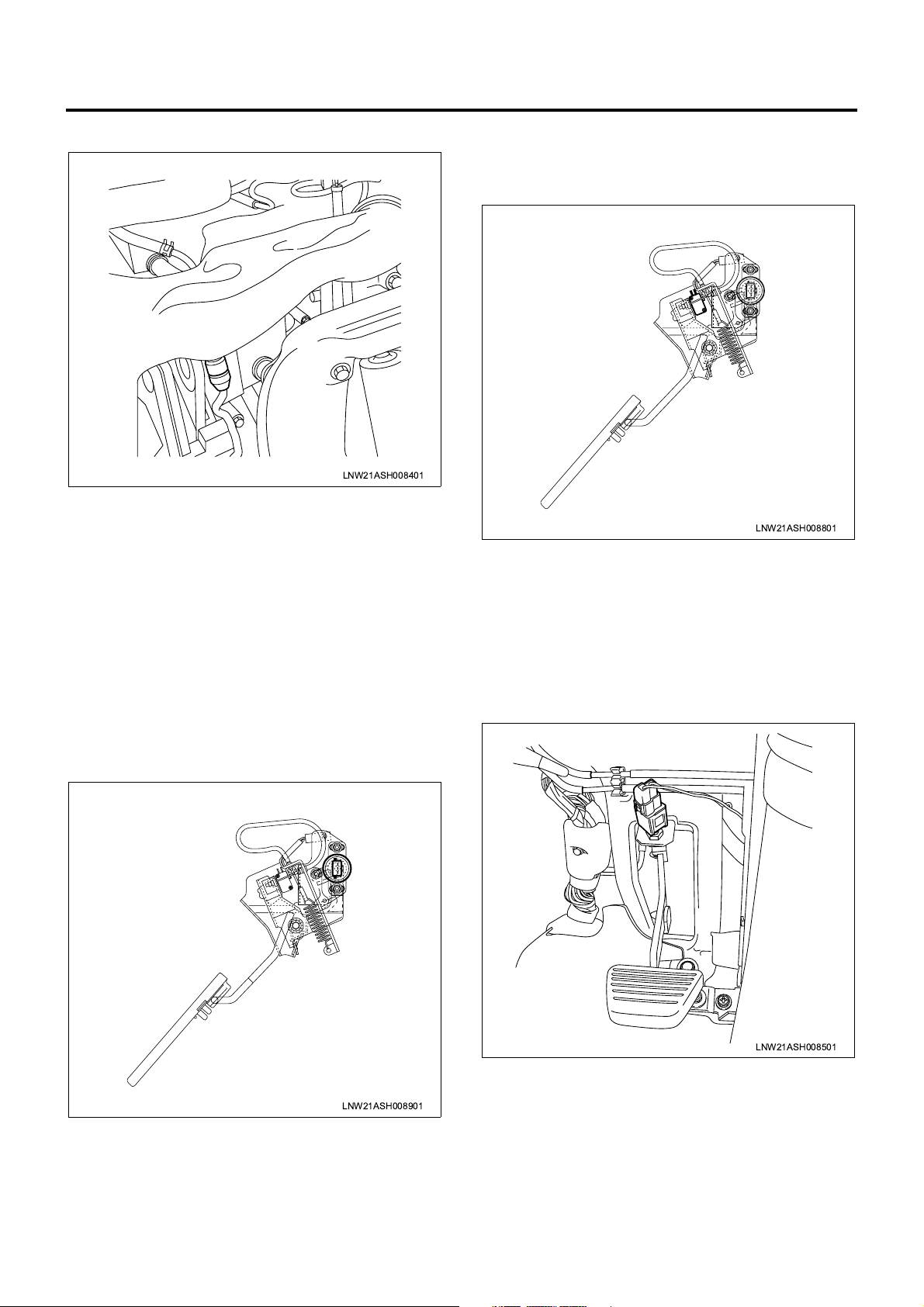
IAT Sensor
LNW21ASH008401
The IAT (intake air temperature) sens or is installed to
the intake air duct and the thermistor in the sensor
alters the resistance in response to the temperature
change. Higher intake air tem per at ure pr ov id es sm a ller
resistance while lo wer intake air temperature prov ides
larger resistance. The ECM supplies 5 V to the IAT
sensor via pull- up resistance a nd calculates the intake
air temperature from the change i n voltage and us es it
in fuel injection control and other control tasks. The
voltage is decrease d when the resistan ce is small (the
temperature is high) while increased when the
resistance is large (the temperature is low).
voltage signal for us e in fuel inje ction con trol and o ther
diversified control tasks.
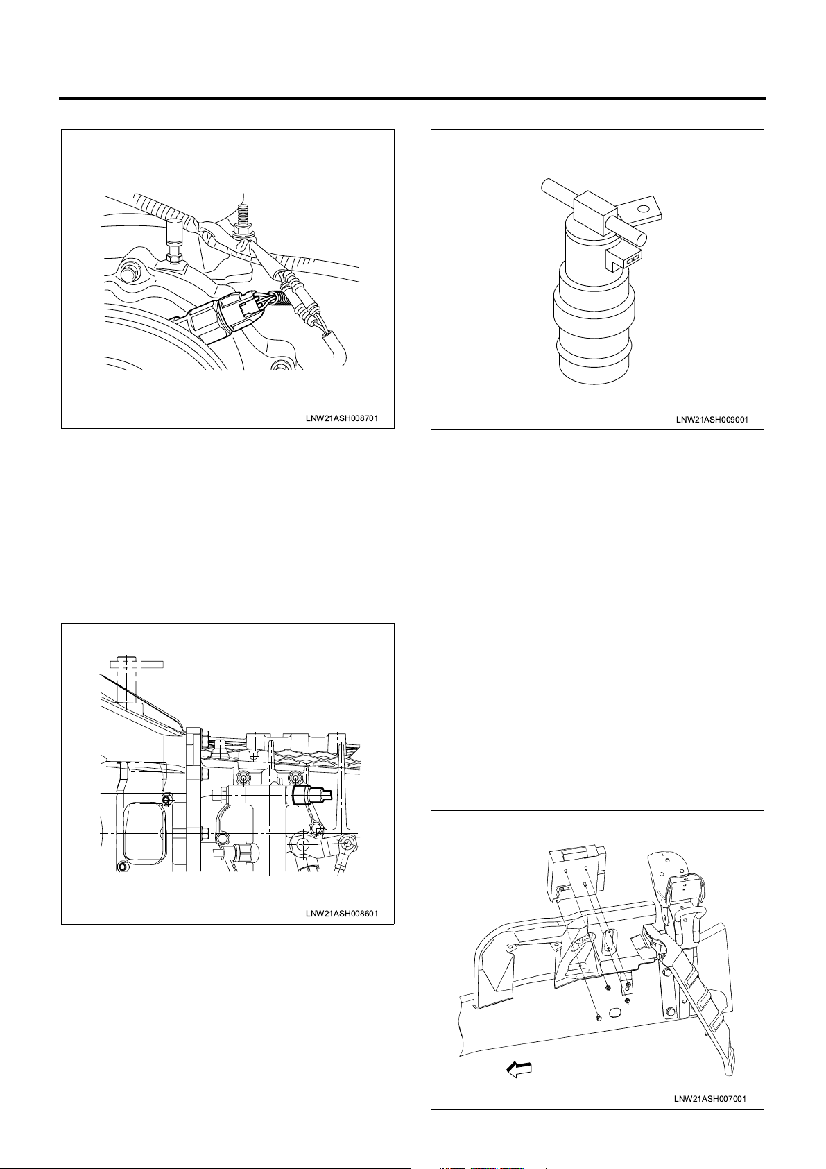
Idle Position Switch
LNW21ASH008801
The idle position switch is installed to the accelerator
pedal, and is turne d off when the pedal is presse d and
turned on when the pedal is released. The ECM
receives the on/off signal fro m this idle position switch
for use in exhaust brake control, warm-up control, and
other control tasks.
Clutch Switch
AP Sensor
LNW21ASH008901
The AP (accelerato r pedal position) s ensor is installed
to the top of the accelerator pedal and supplies the
voltage signal that will change in response to
accelerator pedal angle to the ECM. The ECM
calculates the accelerator pedal position from the
LNW21ASH008501
The clutch switc h is i ns tal led to th e c lu tc h p eda l, and i s
turned on when the pedal is pressed and turned off
when the pedal is release d. The VIM receives the on/
off signal from this clutch switch for use in exhaust
brake control and other control tasks.
1A-14 Engine Control System
VS Sensor
LNW21ASH008701
The VS (vehicle speed) sensor is installed to the
transmission. T he sensor is also equipped with a Hall
effect circuit. The magne t mounted to th e transmis sion
output shaft is rotated together with the shaft to
generate a magnetic field. This Hall effect sensor
interacts with the magnetic field and generates and
sends a signal to the VIM . The VS sens or is ener gized
via meter fu se . T he VI M us es VS s i gn al pu ls es t o j ud g e
the vehicle speed.
Neutral Switch
Exhaust Brake Solenoid Valve
LNW21ASH009001
The exhaust brake solenoid valve is installed to the
rear of the right front wheel frame (s ome vehicle types
have different positions), and opens and closes the
vacuum path connected to the exhaust brake valve.
When this solenoid valve is turned on, the path is
opened and the vacuum is applied to the exhaust brake
valve. When the solenoid valve is turned off, the path is
closed and the atmospheric pressure is applied and
resultantly the exhaust brake valve is released. After
the exhaust brake s witch is turned on and the vehicle
meets all the nece ssary conditions, the E CM turns on
the exhaust brake solenoid valve.
LNW21ASH008601
The neutral switch (P/N switch in case of automatic
transmission) is installed to the transmission (shift lever
in case of automatic transmission), and is turned on
when the shift lever is moved to the neutral position.
The ECM receives the on/off signal from this neutral (or
P/N) switch to control the powertrain so that the dri ver
cannot start the engine as long as the shif t lever is not
in the neutral (or parking) position.
Atmospheric Pressure Sensor
The atmospheric pressure sensor is installed inside the
VIM and converts the atmospheric pressure into a
voltage signal. The VIM calculates the atmospheric
pressure from the voltage signal and sends the result to
the ECM. The ECM u ses this atmosp heric pressure to
calibrate the fuel injection quantity (altitude
compensation).
ECM
LNW21ASH007001
Engine Control System 1A-15
The ECM is installed in the inner par t of the engine lef t
side cover. The ECM uses sign als s en t fr om di ve rsified
sensors to control tho se sys tems direc tly rela ted to the
engine, for example, fuel injection control, intake
throttle control, EGR control, and QWS control.
VIM
LNW21ASH008301
The VIM is installed inside the center console in the
cab, and transmits signals sent from diversified
switches and sensors and drives powertrain actuators
such as exhaust brake, relays, and warning lamps
according to the commands from the ECM.
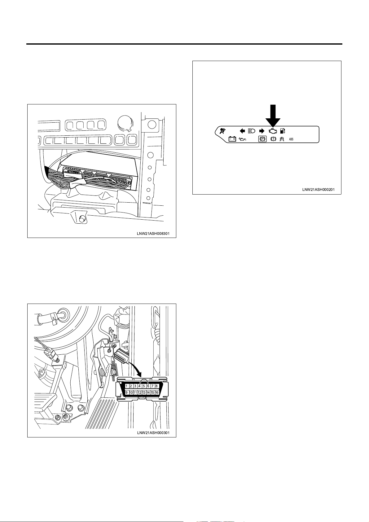
CHECK ENGINE Lamp (MIL)
LNW21ASH000201
The CHECK ENGINE lamp (MIL) is built in the meter
panel and informs th e driver of faulty status of e ngine
or associated syst ems. When the ECM detec ts a fault
by means of its diagnostic function, this CHECK
ENGINE lamp is turned on. A fter the diagnostic sw itch
is turned on (DLC pins are shorted), the CHECK
ENGINE lamp blinks to inform the mechanic of
detection of DTC.
DLC
87654321
161514131211109
LNW21ASH000301
DLC (data link connec tor) is installed to the da sh side
pane of the driver ’s seat and acts as a communicat ion
interface between external diagnostic tool and onboard controllers. The DLC can also function as a
diagnostic switch and when DLC pins are shorted , this
diagnostic switch is turned on.
1A-16 Engine Control System
Fuse Layout
[Fuse Box Label, In Glove Box]
22
19
16
13
10
1
4
7
25
23
26
[Fuse Box, Front Left of Radiator]
24
1
20
21
17
18
27 28
14
15
11
12
2
5
8
6
9
3
LNW21ALF000401-X
Legend
1. Spare fuse
No. Indication on label Capacity Devices connected
1 CONTROLLER 10A Control unit
HAZARD,HORN (12V) 15A
2
Hazard warning flashing lamp, horn
HAZARD,HORN (24V) 10A
3—10A—
AIR CON (12V) 10A Air conditioner
4
HEATER,AIR CON (24V) 15A Heater, air conditioner
5 FUEL, SEAT HEATER (24V) 10A Fuel, seat heater
6 ABS, HAB, RETARDER (24V) 15A ABS, HAB, retarder
7 ROOM LAMP 15A Room lamp
8 STOP LAMP 10A Stop lamp

Engine Control System 1A-17
No. Indication on label Capacity Devices connected
9 POWER WINDOW (24V) 20A Power window
10
11 FOG.CORNER 10A Fog lamp, cornering lamp
12 ELEC.PTO (24V) 10A PTO switch (electric PTO)
13 WIPER,WASHER 15A Wiper, window washer
14 TURN 10A Turn signal lamp
15
16
17 MIRROR 10A Electrically operated mirror
18 CIGAR,AUDIO 10A Cigarette lighter, audio
19
20
21 AIR BAG 10A SRS airbag
TAIL.ILLUMI (12V) 15A
Tail lamp
TAIL.ILUMI (24V) 10A
GENERATOR (12V) 15A Generator
ELEC.PTO (24V) 20A PTO solenoid valve (electric PTO)
MIRROR HEAT (12V) 10A Heated side mirror
ENG.CONT (24V) 15A ECM
METER (12V) 10A
Meter
METER (24V) 15A
ENGINE STOP (12V) 10A Engine stop
HSA (24V) 10A HSA
22 STARTER 10A Starter
23 H/LAMP RH 10A Headlamp, RH
24 H/LAMP LH 10A Headlamp, LH
25
26 POWER WINDOW (12V) 30A Power window
External Fuse Box
No. Indication on label Capacity Devices connec te d
27 MARKER LAMP 10A Marker lamp
28 COND FAN 10A Condenser fan
HEATER (12V) 30A Heater
ENG CONTROLLER (24V) 30A ECM (except for turbocharged vehicles)

1A-18 Engine Control System
Relay Layout
Relay Box No.2
Bracket
Spare Power Circuit
18
16
15
14
13
Relay Box No.1
8
7
6
5
Upper
12
11
10
9
20
19
Cooler Relay
1
4
3
2
No. Legend
12 V: On relay
1
24 V: C harge relay
2 Horn relay
Fuse &
Relay Box
RightFront
17
LNW21ALF006101-X
12 V: ABS, VSV, FICD, EXH brake, valve (12 V)
3
24 V: Headlamp relay
4Tail relay
12 V: Headlamp relay
5
24 V: 4WD relay
6 Dimmer relay
7 Power window relay
8 Fog lamp relay

No. Legend
9 Cornering lamp relay
10 Air conditioner thermo relay
12 V: C harge relay
11
24 V: Key on relay
12 Heater & air conditioner relay
24 V: PTO cut relay for electric PTO in fire engine (MT)
24 V: PTO solenoid relay for electric PTO (AT)
12 V: Exhaust brake cut relay (MT)
13
24 V: Idle on relay for fire engine (AT)
24 V: Idle stop, wiper relay (with CFS (clutch free system))
24 V: PTO solenoid relay for electric PTO (MT)
24 V: PTO buzzer relay for electric PTO (AT)
12 V: OD off relay (AT)
14
24 V: Idle keep relay for fire engine (AT)
Engine Control System 1A-19
24 V: Idle stop, radio relay (with CFS)
24 V: PTO main relay for electric PTO (MT)
24 V: Garbage relay for garbage collector (AT)
15
24 V: Indicator lamp relay for fire engine (AT)
24 V: Idle stop, engine control module relay (with CFS)
4WD relay
16
24 V: Idle stop, mirror relay (with CFS)
24 V: Full automatic air conditioner, high relay
17
24 V: Automatic air conditioner, high relay
24 V: Shift lock relay for fire engine (AT)
24 V: Shift relay for fire engine (AT)
18
24 V: PTO main relay for electric PTO (MT)
19 24 V: PTO solenoid relay for electric PTO (MT)
20 24 V: PTO cut relay for electric PTO (MT)
1A-20 Engine Control System
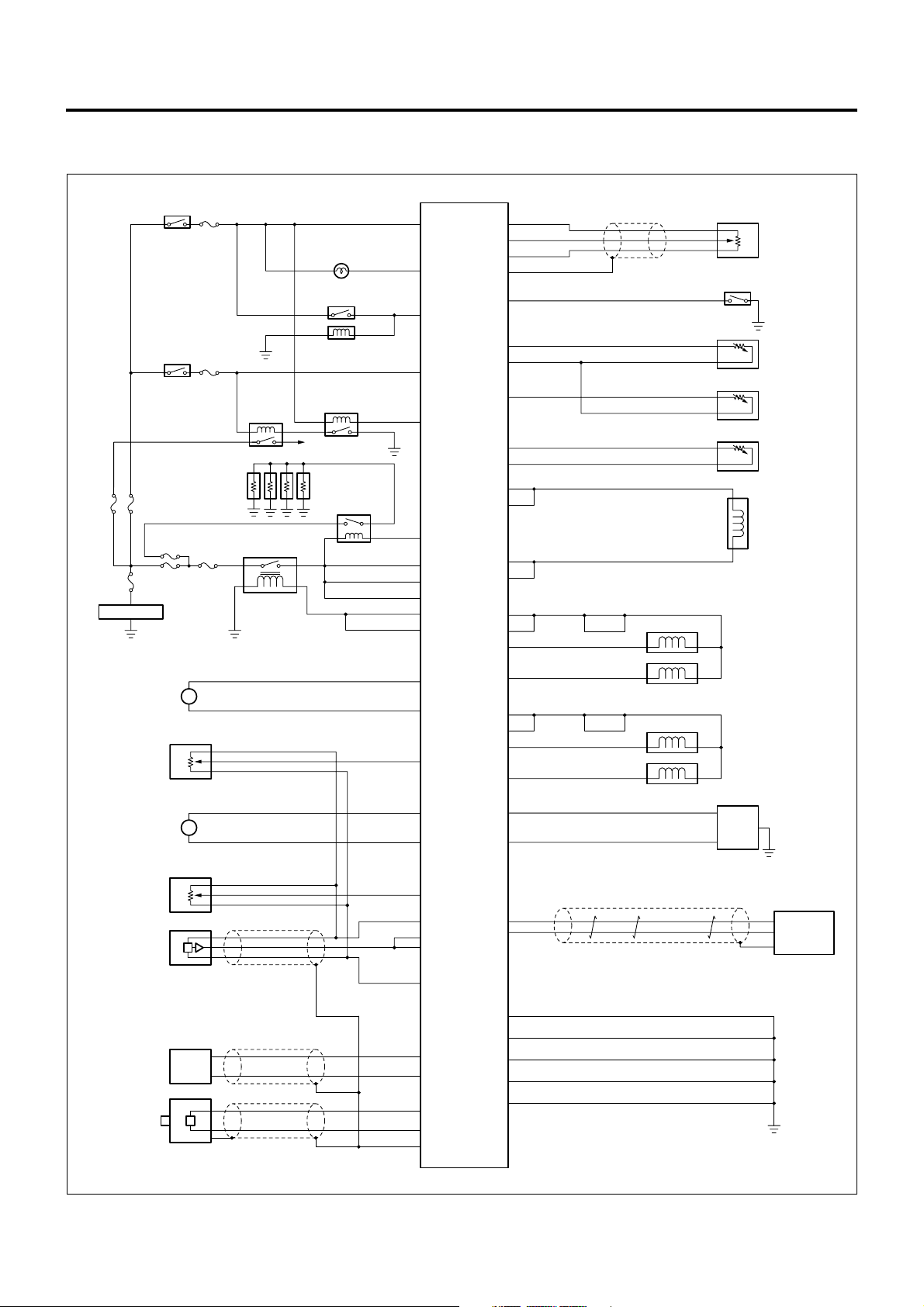
Circuit Diagram
ECM Circuit Diagram
Starter
Switch (ON)
SBF
60A
100A
SBF
Battery
Intake
Throttle
DC Motor
ITP
Sensor
EGR
DC Motor
Starter
Switch (ST)
SBF
50A
SBF
60A
SBF
50A
M+
M-
M+
M-
#19
15A
#22
10A
SBF
30A
M
M
Starter
Relay
Glow
Plug
Main Relay
CHECK ENGINE
A/C Condenser
A/C Magnetic
Cut Relay
To Starter
Lamp
Clutch
Starter
Glow
Relay
0.75B/O 0.5L
0.5Y/B
0.75W/R
0.5B/W
0.5B/R
0.5W/G
1.25W/R
1.25W/R
1.25W/R
0.5L/Y
0.5L/Y
0.75W/G
0.75R
0.5G/Y
0.75W/B
0.75L/Y
109 90
99
13
113
102
98
114
115
116
117
118
16
ECM
35
69
59
58
84
94
108
110
49
46
48
91
83
80
81
74
75
43
42
24
23
88
112
0.5L/W
0.5L/R
0.5B/Y
0.5W/L
0.5R/B
0.5G/W
0.5R/G
0.85L/B
0.85O
0.75W/R
0.75W/R
0.75L
0.75L
1.25W
1
2
1.25L/W
0.75G/W
0.75B
1.25R
4
5
1.25L/R
0.75W/Y
0.75L
0.5SB
0.5GR/W
Idle Position Switch
Scan Tool Communication
Diagnostic Switch
AP
Sensor
ECT
Sensor
FT
Sensor
IAT
Sensor
SCV
Cylinder 1 Injector
Cylinder 4 Injector
Cylinder 3 Injector
Cylinder 2 Injector
DLC
EGR Valve
Position
Sensor
Common Rail
Pressure
Sensor
CKP
Sensor
CMP
Sensor
0.5Y
0.5W
0.5G
0.5G
0.5R
0.5W/R
0.5W/L
0.5L/R
0.5L/W
0.5B
68
0.5R
63
67
66
64
25
6
8
27
26
89
97
87
95
119
120
121
0.5W
0.5B
0.85B
1.25B
1.25B
1.25B
VIM
0.5B
LNW21AXF002601-X

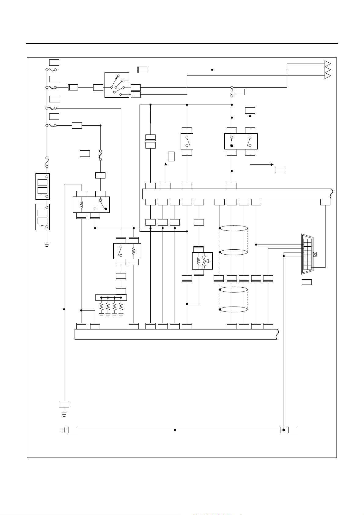
VIM Circuit Diagram
Engine Control System 1A-21
SBF
50A
SBF
100A
Battery
Starter SW (ON)
Starter SW (ST)
SBF
SBF
30A
50A
#19
15A
Exhaust
Brake Lamp
Exhaust
Brake Solenoid
PTO Lamp
PTO SW
#22
Main Relay
10A
Glow Lamp
ECO Relay
Clutch SW
Exhaust Brake SW
Warm Up SW
M/T : N A/T : P or N
Freezer SW
CFS Non Vehicle
PTO ECU
CFS Vehicle
CFS
0.85B/O
0.3BR/W
0.5LG/B
0.5V/W
0.5B/W
1.25W/R
1.25W/R
1.25W/R
0.3O/L
0.5G/Y
0.5W/L
0.5LG/R
0.5BR/R
0.5B/G
0.5L/B
36
0.5B/R
4
2
7
46
38
75
76
16
0.3B/G
53
0.3LG/B
56
18
59
17
15
19
57
54
0.5BR
0.5B/R
0.3B/L
0.5G/Y
0.5G
0.5L/R
0.5LG
A/T ECU
Tachometer
ABS/ASR
ECU
Sound Alarm
(Simplified ISS)
CFS ECU
42
3
49
50
12
44
47
V I M
27
26
48
0.5W
0.5R
0.5B
0.5G/W
Lamp
Fail Relay
ECM
Brake SW
+B
Stop
Lamp Relay
Other ECU
PTO
Accelerator
Sensor
Idle Up
Volume
VS Sensor
0.5Y/BR
0.5Y/G
0.5R/B
0.5Y
0.5Y/G
9
0.5SB
24
34
31
71
30
14
0.5B
73
0.85B
60
0.85B
39
0.85B
52
0.85B
66
Diagnostic SW
DLC
Scan Tool Communication
LNW21AXF002301-X
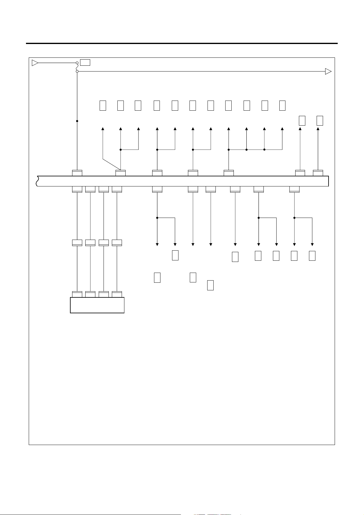
1A-22 Engine Control System
ECM/VIM Circuit Diagram (1/5)
MAIN
KEY
GLOW
ECM
2L
+
P-1
P-2
+
P-3
P-4
Frame
SBF-1 80A/100A
SBF-2 50A
3 W/L
SBF-3 60A
SBF-5
50A
3 W/G 3 W/G
0.5
B
B-67
B-67
1
H-6
3
4
3B/Y
3B/W
5 W/B 5 W/B 3 W/B
OFF
ACC
H-7
B-67
21
3 W/L
ON
B
ST
Starter Switch
2
H-7
F-25 30A
ENG.CONT
X-18
Main Relay
X-182X-18
0.5
L/Y
0.5
L/Y
117
J-191
3
5
W/R
Glow Plug
0.5
L/Y
3
J-191
W/G
W/G
W/G
3
2
2
118
H-4
X-18
0.3
B/O
1
B-355
B-354
1
Air Bleed Connector
0.3
J-191
0.85
B/O
98
P
10 49
B-352
B-349
38
1.25
W/R
H-4
Glow Relay
1.25
W/R
114
J-191
0.5
LG/L
B-352
B-34975B-349
1.25
W/R
8
H-4 H-4
1.25
W/R
J-191
9
3
B/L
1
3
0.5
B/L
W/R
2
X-224X-22
X-225X-22
3
3
B/G
2
H-105
3
0.5
B/G
W/G
E-3
B/O
B-258 (2)
CFS Control Unit
W/L
76
1.25
0.85
W/R
B/O
67
0.85
B/O
1.25
0.75
W/R
B/O
0.75
B/O
115
116
J-191
0.5
0.5
B-352
B-349
J-191
B-89
B-89
H-5
109
1
2
49
36
0.5
LG/B
0.5
LG/B
8
0.5
B/O
Clutch Switch
B-352
2
19
H-4
2
J-31
J-31
1
B-350
0.5
B
Exhaust Brake
Solenoid Valve
ECM
F-16 15A
ENG. CONT
PTO Cut Relay
B/O
B/O
0.5
0.5
B-216 (4)
0.5
R/Y
21
B-89 B-89
Clutch PTO Switch
B-894B-89
3
0.5
0.5
G/O
B/O
0.5
B/O
49
B-352
VIM
B-350
B-350
B-350
26
65
0.5R0.5
W
4
H-413H-412H-48H-81H-8
0.5R0.5
W
97
J-19189J-19188J-191
24
27
0.5
LB
0.5
GR/W
J-191
PTO Solenoid M/T Relay
B-64 (3)
0.5 LB
0.5 GR/W
0.5 B
0.5 B
Diagnostic Connector
0.85
B
112
12345678
B-79
A
C
B
B-352
9
10111213141516
0.5 L
9
Left Side Frame
Right Frame (Front)
3
B
J-9
(Center)
B-274
3 B 1.25 B
6
8
B-274
Joint Connector
LNW21AXF002701-X

Engine Control System 1A-23
ECM/VIM Circuit Diagram (2/5)
Charge Relay
0.3
B
0.5
LG/R
B-35166B-349
B-352
39
3B/Y
X-1
Idling Stop &
Warm Up Switch
(10A)Fuse
F-10
52
(4)
B-172
Joint
Connector
0.3
B/R
0.5
B
35
B-31 B-31
B-312B-31
6
0.5
LG/R
12
TAIL,ILLUMI
B-352
B-35073B-349
60
3B/W
67
1.25B
8
F-10
GND
B-274
Warm Up Switch
(10A)Fuse
VIM
B-349
71
F-19
Meter
1
2
Joint
Connector
31
H-5
0.85
B/Y
0.5
B/Y
1
J-50
J-50
2
0.5
B/G
14
H-4
0.5
B/G
44
B-352
SIG SIG5VGND
B-34934B-349
31
15A
B-172
Neutral
Switch
(M/T)
TCM
B-47
(JATCO)
0.3
W/L
0.3
W/L
44
B-352
12
Inhibitor Switch
(AISIN)
NP
J-69
J-69
5
W/L
W/L
0.5
0.5
0.5
W/R
20
H-4622H-46
0.5
W/R
7
X-33
X-33
6
8
Diode
X-33
9
0.5
B/G
44
B-352
B-349
30
A
3W/B
C
B D
12
X-12 X-12
X-12
3
5
B/R
FUEL, SEAT HEATER
0.5
B/R
0.5
5
B/R
B-69
B-69
2
0.5
LG/R
50
B-352
X-12
10A
F-5
Switch
Exhaust Brake
0.5W/R
Heater & A/C
Relay
4
0.5B 0.5B
0.5
BR
62
B-319 B-319
B-3195B-319
3
12
TAIL,ILLUMI
B-352
B-352
47
0.85
0.5
L/B
0.5
0.85
B
B
B
B
B
0.5
0.85
0.85
0.5
0.5Y0.5
Y/BR
B-2821B-3253B-282
R/B
1
PTO Accelerator Sensor
0.5
0.5
Y/BR
Y/G
1
B-2812B-2813B-281
Idle Control Switch
0.5
R/B
Y/BR
55
0.5
Y/BR
1
J-1662J-166
0.5Y0.5
H-4H-8
0.5Y0.5
R/B
73
H-8 H-8
0.85
R/B
J-166
L/B
3
J-7
1
PTO Accelerator Sensor
Compressor
Left Frame (Front)
B-346
LNW21AXF002801-X
1A-24 Engine Control System
ECM/VIM Circuit Diagram (3/5)
D
3B/W
0.5
B/W
F-22
STARTER
10A
0.5B/W
E
B-259 6
CFS C/U
0.5
B/W
B-352
B-351
0.3
B/L
H-8
0.3
B/L
J-1778J-17719J-17720J-177
0.5
L/R
46
B-351
B-35117B-351
15
19
12
7
B/R
0.5
LG/W
0.5
H-8
G/Y
11
G/Y
57
0.5
18
H-817H-8
0.5
EHCU
G/B
0.3
B-351
B-229 5 (AISIN)
TCM
18
B-47 20 (JATCO)
TCM
B/G
0.3
B-351
B-229 23 (AISIN)
TCM
53
B-47 13 (JATCO)
TCM
0.3
LG/B
B-351
B-230 7 (AISIN)
TCM
56
B-47 8 (JATCO)
TCM
B-52 8 (Tachometer)
Meter
0.5
LG
59
B-351
0.3
LG
B-229 1 (AISIN)
TCM
0.5
LG
B-48 4 (JATCO)
TCM
B-259 1
CFS
X-15 3
B-147 3 (Idling Stop)
Parking Warning Unit
Idling Stop ECM Relay
0.5
LG
0.5
0.5
G
G/Y
54
B-3513B-352
VIM
B-351
14
0.5
BR
0.5
BR
Y/G
0.5
B-52 17 Speed Meter
Meter
B-35242B-352
0.3
BR/W
J-32 3
Speed Sensor
4
0.3
O/L
B-51 6 EXH Brake W/L
B-52 15 Glow Indicator Lamp
Meter
0.5
W/O
B-352
11
B-259 19
CFS C/U
B-352
48
0.5
G/W
X-3 2
Stop Lamp Relay
B-352
7
0.5
V/W
B-84 2
B-66 2
PTO Switch (M/T)
Stop Lamp Switch
B-77 1
Dump Control Switch
Meter
LNW21AXF002901-X
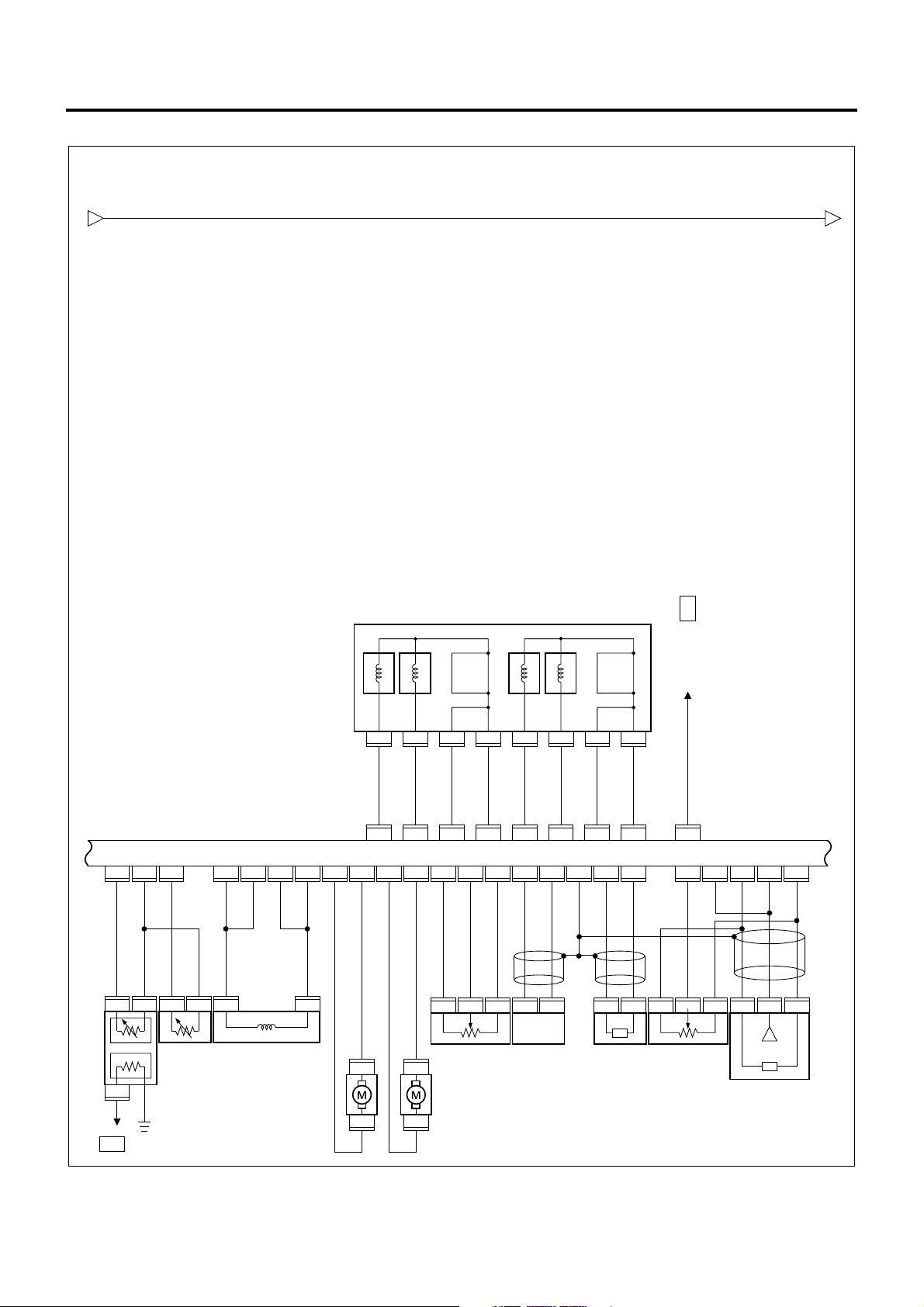
ECM/VIM Circuit Diagram (4/5)
Engine Control System 1A-25
E F
0.5B/W
Injector
E-5 (1)
E- 11154E- 11119E- 111
22
0.5
0.5
0.5
R/B
0.5
Y/B
R/G
G/W
0.5
G/W
1
E-902E-902E-931E-931E-116
E-90
3
0.5
G/W
Fuel
Temperature
(FT) Sensor
Meter
B-52 (5)
No.2 No.3 No.4 No.1
E-115
6
0.75
L
E- 11133E- 11134E- 11117E- 11112E- 11129E- 11146E- 11145E- 111
0.75
W/R
0.75
W/R
16
0.75
0.75
L
W/R
Suction Control
Valve (SCV)
0.75L0.75
0.75
L
E-116
0.75
0.75
W/G
0.75
E-114
E-114
R
L/Y
0.75
L/Y
3
Intake Throttle DC Motor
6
R
0.75
R
2
E-1153E-1158E-1155E-1151E-1154E-115
0.75
W/Y
E-115
E- 1114E- 111
2
7
0.75
0.75
1.25
1.25
L/R
R
2426
G/W
B
ECM
E- 1111E- 11156E- 11136E- 11137E- 11152E- 11118E- 11135E- 111
0.75
W/B
0.75
E-94
E-94
L/Y
G/Y
W
4
E-1142E-1141E-1141E-982E-98
Intake Throttle
4
Position (ITP)
Sensor
EGR DC Motor
6
39
0.5
0.5
0.5
R
0.5
0.5
W/L
W/R
Crank Position
(CKP) Sensor
Magnetic Clutch
3013793215
0.5
W
0.75
W/R
13
E- 111
E- 111
2
0.5
Y
EGR Position
Sensor
E- 11138E- 111
21
0.5G0.5
0.5
R
W
1.25
1.25
L/W
W
E- 111E- 111E- 111E- 111E- 111E- 111
0.5
0.5
0.5
B
L/W
L/R
3
E-1122E-1121E-943E-942E-943E-1132E-1131E-113
Cam Position
(CMP) Sensor
E- 111
E- 111
455
0.5
G
0.5G0.5
R
Common Rail
Pressure Sensor
LNW21AXF003301-X
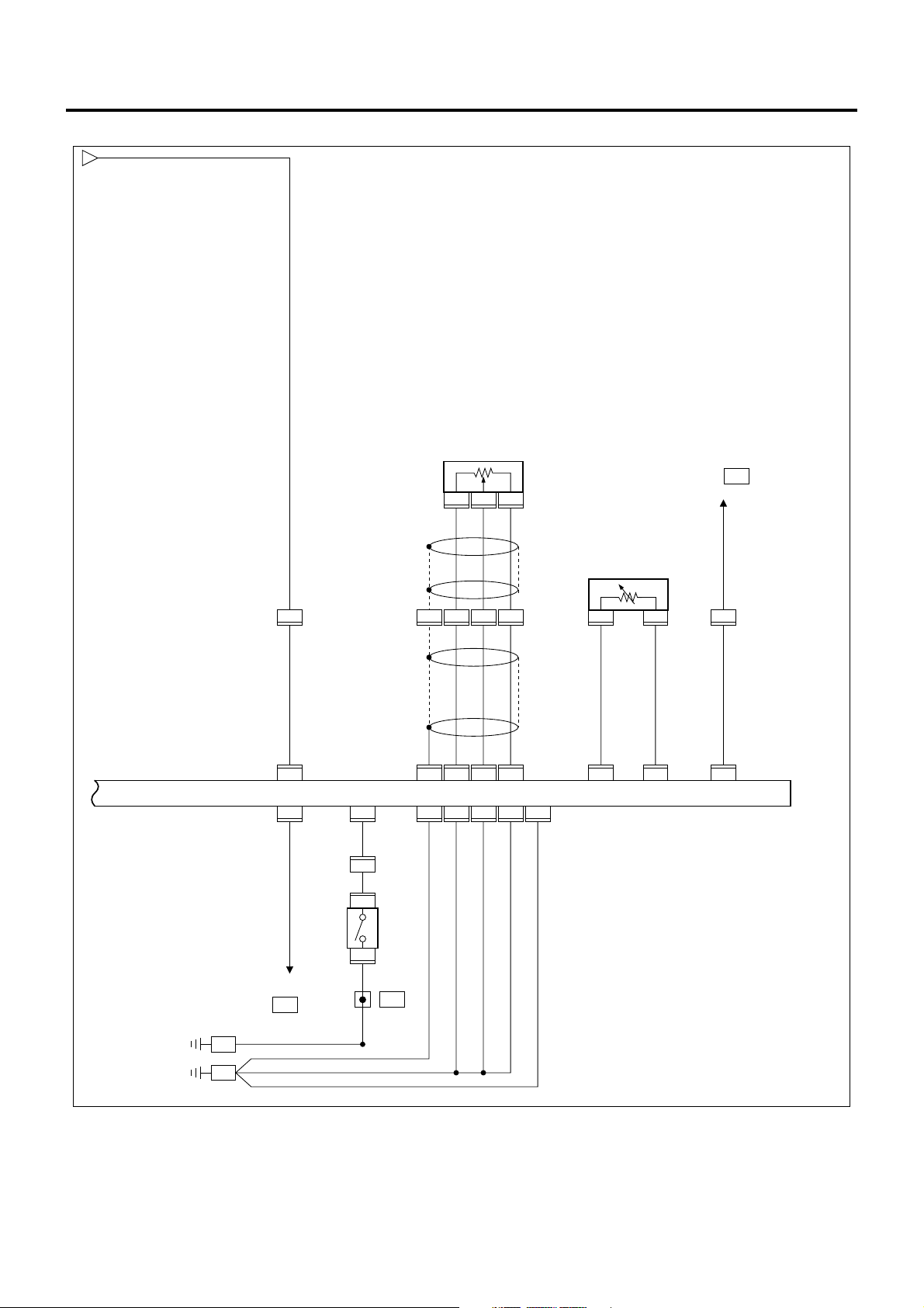
1A-26 Engine Control System
ECM/VIM Circuit Diagram (5/5)
F
0.5
B/W
Accelerator Sensor
B-2802B-2801B-280
3
Meter
B-51 5
(CHECK ENGINE Lamp)
Right Frame (Front)
B-274
0.5
L
30
H-5
0.5
B/W
113
J-191 J-191
ECM
J-191
102
0.5
B/R
Starter
Cut Relay
X-26
J-191
110
0.5
W/L
2
H-8
0.5
W/L
1
B-75
Accelerator
Pedal
Switch
B-75
2
0.5
B
10
1.25
B
B-172
6
Joint
Connector
3
3B
10
H-4
H-43H-42H-4
0.5
L
0.5
B/Y
108
J-19190J-191
5V GNDSIG 5V SIG
J-191
J-191
95
0.75
1.25
B
B
121
L/R
L/W
1
0.5
0.5
L/R
L/W
94
84
J-191
J-191
J-191
J-191
J-191
120
119
87
0.5
1.25
1.25
B
B
B
0.85
J-190
O
J-191
IAT Sensor
2
83
J-190
1
0.5
L/B
91 99
J-191
0.5
0.5
0.5
Y/B
4
H-8
0.5
Y/B
Left Frame (Center)
J-9
LNW21AXF003101-X

Component Layout
Engine Control System 1A-27
56
55
54
53
52
51
50
49
48
47
41,42,43,44,45,46
40
57
39
32
31
1
2,3
4
5
6
7
8
9
25
24
10
12
11
13
14
15
16
17
Legend
33,34,35,36,37,38
26,27,28,29,30
23
22
21
20
1 B-172 Joint connector
2 X-12 Heater and air conditioner relay (825/151)
3 X-33 Diode (810/002)
4 B-349, 350, 351,
VIM (826/646)
352
5 J-31 Exhaust brake magnetic valve (156/086)
6 J-50 Neutral switch (230/171)
7 J-166 PTO accelerator sensor (101/867)
8 P-5 Frame ground
9 P-1 & P-2 Battery
10 P-3 & P-4 Battery (24 V)
11 E -3 Glow plug (011/010)
12 E-115 Injector (040/031)
13 E-113 Common rail pressure sensor (040/21 1)
14 E-94 EGR vacuum sensor (057/667)
14 E-94 EGR valve (057/001)
15 E-114 Intake throttle position sensor (025/373)
18
19
LNW21ALF006301

1A-28 Engine Control System
15 E-114 Intake throttle motor (025/373)
16 E-98 Crank position sensor (826/648)
17 E-112 Cam position sensor (040/001)
18 E-96 Timing control valve (040/001)
18 E-111 ECM (060/613)
19 H-105 Intermediate connector
20 J-190 IAT sensor (060/820)
21 E-116 Su ction co ntr ol valv e (040/001)
22 E-93 Fuel temperature sensor (040/205)
23 E-90 Engine coolant temperature sensor (060/129)
24 J-69 Inhibitor switch (249/001)
25 J-9 Left frame (center) ground
26 F-5 Fuel seat heater fuse (810/005)
27 F-16 ENG.CONT fuse (810/005)
28 F-19 Meter fuse (810/005)
29 F-22 Starter fuse (810/005)
30 F-25 Engine controller (main) fuse (810/005)
31 B-346 Left frame (front) fuse
32 J-7 Compressor connector
33 SBF-1 Main slow blow fuse (810/174)
34 SBF-2 Key switch slow blow fuse (810/174)
35 SBF-3 Glow slow blow fuse (810/174)
36 SBF-5 ECM slow blow fuse (810/174)
37 X-18 Main relay (828/531)
38 X-22 Glow relay (060/046)
39 J-177 EHCU (350/089)
40 B-274 Right frame (front) ground
41 H-4 Intermediate connector
42 H-5 Intermediate connector
43 H-7 Intermediate connector
44 H-8 Intermediate connector
45 H-6 Intermediate connector
46 H-46 Intermediate connector
47 B-354 Air ve nt conn ec tor
47 B-355 Air ve nt conn ec tor
48 B-89 Clutch switch (825/021)
49 B-67 Starter switch (431/103)
50 B-69 Exhaust brake switch (825/001)
51 B-79 Diagnostic connecto r (DL C)
52 B-75 Accelerator switch (101/079)
53 B-280 Accelerator position sensor (101/243)
54 B-282 & B-325 PTO accelerator connector
55 B-281 Idle up position switch (101/262)
56 B-51 & 52 Meter warning (821/001)
57 B-31 Warm-up switch (825/423)
Loading...