


ET90000 Series
Electronic Timer
Installation and Programming Guide
 WARNING Risk of Fire or Electric Shock
•Do not attempt to install or use your Intermatic product until you have read the safety instructions in this section. Save this document and keep it in an easily accessible place.
•To avoid fire, shock, or death, turn off power at circuit breaker and test that power is off before wiring.
•Observe all national and local electrical and safety codes.
•Disconnect power when servicing or changing loads.
•Alterations or modifications to the device will create a hazard.
•Use copper conductors only. Use 10 AWG wire, minimum 105°C for 30 Amp loads.
•For outdoor locations, rainproof or wet location conduit hubs that comply with the requirements of UL 514B Conduit, Tubing, and Cable Fittings for outdoor use, must be used.
www.intermatic.com
7777 Winn Road
Spring Grove, IL 60081 Manual No. 158--01050-REVA

Table of Contents |
|
Safety Information..................................................... |
2 |
Unpacking................................................................. |
2 |
Quick Start Guide..................................................... |
2 |
Product Description.................................................. |
3 |
Installation................................................................. |
4 |
Mounting.............................................................. |
4 |
Wiring................................................................... |
5 |
Door Assembly..................................................... |
8 |
Controls..................................................................... |
9 |
Programming.......................................................... |
10 |
Advanced Options.................................................. |
12 |
System Configuration Options................................ |
14 |
Limited Three-Year Warranty.................................. |
16 |
Français.................................................................. |
17 |
Español................................................................... |
33 |
Safety Information
 WARNING
WARNING indicates a hazardous situation which, if not avoided, could result in death or serious injury.
 CAUTION
CAUTION indicates a hazardous situation which, if not avoided, could result in minor or moderate injury.
IMPORTANT is a statement that informs about installation, operation, maintenance, performance issues, or general tips that are important but do not create a hazard or safety concern.
EMISSIONS: This device complies with Part 15 of the FCC Rules.
This Class A digital apparatus complies with Canadian ICES-003.
IMPORTANT: Changes or modifications not expressly approved by the party responsible for compliance could void the user’s authority to operate the equipment.
Unpacking
Separate the timer from packaging materials and check for any visual signs of damage. If you determine there has been damage caused by shipping, file a claim
with the shipping company. If the device appears to have been improperly assembled or does not operate properly, return it for replacement or repair (see Limited Three Year Warranty information at the end of this manual).
Quick Start Guide
1. Mount Unit
Mount the unit to a stable surface, as required (see Mounting, page 4).
2. Connect to Power
 WARNING
To avoid fire, shock, or death, turn off power at circuit breaker and test that power is off before wiring.
Connect unit to power (see Connect to Power, page 5).
3. Install Wiring
 CAUTION
Some terminals in the ET90000-series electronic timer may be energized even if the Status Screen is off. Check all terminals and wires with an appropriate voltmeter before touching.
Wire applications to device as required (see Install Wiring, page 6).
4. Program Basic Information
Input the current date and time. To begin using an application, program an event. For complete information, see Programming, page 10.
2 |
ET90000 Series Electronic Timer |
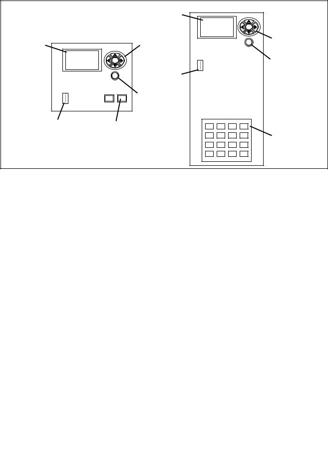
Product Description
|
|
|
STATUS SCREEN |
STATUS SCREEN |
|
2-circuit control module |
NAVIGATION KEYs |
|
|
||
|
|
ENTER |
|
|
|
ESC |
USB PORT |
|
|
|
ESCAPE KEY |
|
USB PORT |
MANUAL |
|
|
|
|
|
|
|
CIRCUIT ON/OFF KEYs |
|
4 to 16-circuit control module |
|
ENTER |
|
ESC |
NAVIGATION KEYs |
|
ESCAPE KEY |
|
MANUAL |
|
CIRCUIT ON/OFF KEYs |
The ET90000-series electronic timer from Intermatic is a microprocessor based unit that allows you to turn
your application ON or OFF automatically for worry-free operation. Automatically bring up and shut down lights, turn on or turn off heating and cooling systems, activate/ deactivate alarms, or start and stop pumps. From the compact keypad, easily program, schedule, and track these “events” by a specific date (January 1, 2014) or by a relative date (for example, the first Monday of January of any year), and by a specific time (11:00 p.m. CST)
or by astronomical time (example: sunrise). Separately program holidays and downtimes, too.
Choose whether your event is going to be a fixed ON or OFF (single ON or OFF time for lights, for example) or pulsed ON (ON time with specified duration, such as ringing an alarm).
You can configure ET90000-series electronic timers to fit your needs. They are available in 1 and 2 circuit models, or 4, 8, 12, 16 circuit models. The smaller units are housed in either a Type 1 indoor enclosure or a Type 3R “rainproof” outdoor enclosure. All 4, 8, 12, and 16 circuit models are housed in the Type 3R enclosure.
Power Ratings
Input: |
120-277 VAC, 50/60 Hz, 16 watts |
|
max. for 1 and 2 circuit unit; 50 |
|
watts max. for larger unit |
Output: |
1 and 2 circuit panel, 60 amps |
|
max.; 4-16 circuit panel, 350 amps |
|
max. (both @25°C). Maximum |
|
amperage for the 4-16 circuit panel |
|
is reduced by 4.4A/°C above 25°C. |
General Purpose and |
20 amps (N.O.), 10 amps (N.C.) |
Resistive @ 12-240 VAC: |
|
General Purpose and |
30 amps (N.O.) |
Resistive @ 12-240 VAC: |
|
Resistive @ 28 VDC: |
20 amps (N.O.), 10 amps (N.C.) |
Ballast @ 120-277 VAC: |
20 amps (N.O.), 3 amps (N.C.) |
Tungsten @ 12-120 VAC: |
5 amps (N.O.) |
Motor @ 120 VAC: |
1 HP (N.O.), 1/4 HP (N.C.) |
Motor @ 240 VAC: |
2 HP (N.O.), 1/2 HP (N.C.) |
Pilot duty 120-240 VAC: |
470 VA (N.O.), 275 VA (N.C.) |
Maximum number of 30A |
11 |
circuits (larger unit): |
|
Maximum short circuit |
5,000 amps |
rating both units: |
|
Features
•Automatic input voltage selection (no switches or DIP settings)
•Date and time retention via 100-hour supercapacitor
•USB port for input
•Program up to 4000 events, 99 holidays
•Sunrise/sunset tracking without Photocontrol
•Automatically adjusts for daylight saving time
•Upgrade firmware on-site via USB and Ethernet
•Ethernet connection for PC control and connecting multiple timers
•External device support with CAN and serial ports
ET90000 Series Electronic Timer
Notes:
•N.C = normally closed, N.O. = normally open
•All VAC ratings are for 50/60 Hz
maximum loading examples
Example:
(30 amps x 11 circuits) = 30 x 11 = 330 amps
Example:
(30 amps x 5 circuits) + (20 amps x 10 circuits) = (150) + (200) = 350 amps
3

Technical Data
•Operating temperature: -40°F to 104°F (-40°C to 40°C)
•Dimensions 1 and 2 circuit unit (Type 1 encl.): 7-7/8 H x 5 W x 3 inches D (20.0 H x 12.7 W x
7.6cm D)
•Dimensions 1 and 2 circuit unit (Type 3R encl.): 9-7/8 H x 5-5/8 W x 3-5/8 inches D (25.1 H x
14.3W x 9.2 cm D)
•Dimensions 4, 8, 12, 16 circuit unit: 19-1/8 H x 12 5/8 W x 5-3/8 inches D, including mounting bracket; (48.6 H x 32.1 W x 13.7 cm D)
•Knockout placement and sizes: for 1-2 circuit, 1/2- 3/4 inch combo on back, each side, and two on bottom; for 4-16 circuit, 1/2-3/4 inch combo on each side and six on bottom, 3/4-1 inch combo on each side and four on bottom
•Weight: 1 and 2 circuit device, Type 1 encl.: 2.5 lbs. (1.13 kg); 1 and 2 circuit device, Type 3R encl.:
3.4lbs. (1.54 kg); 4-16 circuit unit: 18.6 lbs. (8.4 kg)
IMPORTANT: See Connecting to Power and Installing Wiring below if you are going to bring power wires and wires for connecting to applications through the back of the enclosure. Connect these wires before mounting unit.
4.Drill holes.
5.Install anchors in wall, if needed.
6.Install the top screw first and then hang the enclosure.
7.Install the remaining screws through the enclosure and into the wall.
8.Close enclosure door.
Mounting (4, 8, 12, 16 Circuit Enclosure)
IMPORTANT: Mounting screws and anchors not included. Recommended screw size is #10; however, the type of screw you select depends on the mounting surface.
1. Install Brackets
Installation
 CAUTION
For outdoor locations, rainproof, or wet location, you must use conduit hubs that comply with the requirements of UL 514B Conduit, Tubing, and Cable Fittings. For Outdoor Installation, Fittings shall be identified with an enclosure type designation (Type 3, 3X, 3S, 3SX, 3R, 3RX, 4, 4X, 6 or 6P) or as rain-tight or liquid-tight on the carton. For indoor/outdoor locations, provide sufficient space around the enclosure for convection cooling.
BRACKET MOUNTING SCREWS (4)
MOUNTING BRACKETS (2)
Mounting (1 and 2 Circuit Enclosure)
IMPORTANT: Mounting screws and anchors not included.
1.Open the enclosure door.
2.Select the knockout you would like to use. Remove the inner 1/2-inch knockout by inserting a flathead screwdriver in the slot; carefully punch the knockout loose. Remove slug. If 3/4-inch knockout is required, remove the outer ring with pliers after removing the 1/2-inch knockout. Smooth edge if necessary.
3.Place the enclosure in the desired mounting location and mark mounting holes.
1.Remove the four hex head screws (5/16" slotted) located on the top and bottom of the outside back of the enclosure.
2.Using the screws that you just removed, install the brackets with the keyhole portion extending past the edge of the enclosure and providing an offset from the back of the enclosure.
4 |
ET90000 Series Electronic Timer |

2. Mount Enclosure
1.Place the enclosure in the desired location and mark the location of at least two of the keyhole openings in the mounting bracket.
2.Drill holes.
3.Install anchors in wall, if needed.
4.Install screws at the keyhole locations.
5.Hang the enclosure on the screws.
6.Mark the location of at least two of the round holes in the bottom bracket.
7.Remove the enclosure from the top screws and drill holes for the bottom screws.
8.Install anchors in wall, if needed.
9.Select knockouts you would like to use. Remove the inner 1/2 or 3/4-inch knockout by inserting a flathead screwdriver in the slot and carefully punch the knockout loose. Remove slug. If a larger knockout
is required, remove the outer ring with pliers after removing the inner knockout. Smooth edge if necessary.
10.Place the enclosure on the wall using the keyholes in the top mounting bracket.
11.Install the remaining screws through the bottom bracket and tighten.
12.Tighten the screws through the top mounting bracket.
13.Close enclosure door before operating.
Connect to Power
 WARNING
To avoid fire, shock, or death, turn off power at circuit breaker and test that power is off before wiring.
 WARNING
Make sure there is no wire insulation under the clamping plate and firmly tighten the terminal screws.
A 120 to 277 VAC power source supplies electricity to the ET90000-series electronic timer, normally run through conduit. To connect the power wires to the unit, follow this procedure:
 CAUTION
Wire in accordance with national and local electrical and safety codes.
|
|
ET90215 2-circuit terminals |
|
|
|||
T |
|
|
|
|
|
|
|
TIMER |
|
|
|
|
|
|
|
AC |
IN |
NC-1 |
NO-1 |
COM1 |
NC-2 |
NO-2 |
COM2 |
1.Secure conduit connectors to conduit before connecting the hubs to the enclosure. After inserting connectors into enclosure, carefully tighten hub lock nut. Do not over-torque.
2.Insert the black power wire into the power board (marked “L1” or “AC”) and secure with a flathead screwdriver.
3.Insert the white neutral wire into the power board (marked “L2/N” or “IN”) and secure with a flathead screwdriver.
IMPORTANT: Color of wires may vary.
4.1 and 2 circuit system: Attach the green ground wire to the green hex head screw at the bottom of the enclosure and secure with a flathead screwdriver.
4, 8, 12, 16 circuit system: Connect the input power wires to the terminals at the top left corner of the device. Connect the ground wire to the green hex head screw at the lower left of the device (see Figure 1).
5.Close enclosure door.
|
|
|
|
|
|
|
|
|
DOOR |
ELECTRICAL |
|
|
|
|
|
|
|
|
SCREW |
|
|
|
|
|
|
|
|
||
|
|
|
|
|
|
|
|
|
|
POWER |
|
|
|
|
|
|
|
|
|
TERMINALS |
|
|
|
|
|
ENTER |
|
|
KEYPAD |
|
|
|
|
|
|
|
|
||
SCREEN |
|
|
|
|
|
ESC |
|
|
|
|
|
|
|
|
|
|
|
||
USB PORT |
|
|
|
|
|
|
|
|
ON/OFF |
|
|
|
|
|
|
|
|
||
|
|
|
|
|
|
|
|
||
|
|
|
|
|
|
|
|
SWITCHES |
|
|
|
|
|
|
|
|
|
|
|
WIRING |
|
|
|
|
|
|
|
|
|
|
|
|
|
|
|
|
|
|
|
|
|
|
|
|
|
|
|
|
|
TERMINALS |
|
|
|
|
|
|
|
|
WIRING |
|
|
|
|
|
|
|
|
|
|
|
|
|
|
|
|
|
|
|
TERMINALS |
GRoundING |
|
|
|
|
|
|
|
|
|
CONNECTION |
|
|
|
|
|
|
|
|
|
|
|
|
|
|
|
|
|
|
Model_TEMP |
|
|
|
|
|
|
|
|
|
|
|
CENTER KNOCKouTS RESERVED FOR |
|
|||||||
|
|
LOW VOLTAGE WIRING |
|
||||||
|
|
|
|
|
|
|
|
|
|
Figure 1: ET90000-Series Unit
(4, 8, 12, 16 circuit model)
ET90000 Series Electronic Timer |
5 |
|

Install Wiring
 WARNING
To avoid fire, shock, or death, turn off power at circuit breaker and test that power is off before wiring.
Observe these regulations before connecting any applications to the device.
•The circuit conductors shall have an ampacity not less than the maximum total load to be controlled.
•Over current protection shall have an interrupting rating sufficient for the application control circuit voltage and the total load current of the equipment being controlled.
•A fuse or circuit breaker shall be connected in series with each ungrounded conductor (and shall be able to open each conductor simultaneously).
•Maximum current rating for each circuit is 30 amps Resistive and General Purpose. Refer to the Power Ratings section on page 3 for other ratings.
Wire components and applications to the terminal boards as needed. Terminal boards are located underneath
the faceplate on the small unit, and on the right and left sides of the large unit. Insert wires into slots; secure with flathead screwdriver.
WIRING INFORMATION – COPPER CONDUCTORS ONLy
|
SUPPLy |
MAX MOTOR Load |
||
WIRE SIZE |
CIRCUIT |
|||
(CONTINUOUS DUTY) |
||||
105°C MIN |
BREAKER |
|||
|
|
|||
INSULATION |
RATING |
120V |
240V |
|
|
|
|
|
|
AWG |
AMP |
HP |
HP |
|
|
|
|
|
|
14 |
15 |
1/2 |
1 |
|
|
|
|
|
|
12 |
20 |
1 |
2 |
|
|
|
|
|
|
10 |
30 |
– |
– |
|
|
|
|
|
|
Terminal block wire gauge range 20 to 6 AWG
Adding Relay Boards (4, 8, 12 Circuit
Systems)
 WARNING
To avoid fire, shock, or death, turn off power at circuit breaker and test that power is off before wiring.
 CAUTION
Some terminals in the ET90000-series electronic timer may be energized even if the Status Screen is off. Check all terminals and wires with an appropriate voltmeter before touching.
You can add additional four-circuit relay boards to the 4, 8 and 12 circuit model to a maximum of 16 circuits per system.
IMPORTANT: Do not exceed 350 amps maximum panel load.
1.Open outer door and remove and retain the two screws that secure the interior deadfront to the chassis.
2.Remove and retain the screw that secures the controller door assembly.
3.Select the position to install the new relay board.
4.Remove and retain the outer two screws that secure the filler panel.
5.Remove the filler panel by bending at the serration until it breaks.
ET90000 SERIES 4-CIRCUIT RELAY BOARD
Circuits 1-4, 5-8, 9-12 or 13-16, depending on slot used


 M NO NC M CONO NC M CONO NC M CONO NC CO
INDEXED PLUG FOR CONNECTION TO INTERFaCE BOard
6.Open the door assembly and remove and retain the two screws just opposite of the filler panel screws.
7.Insert the new relay board assembly into the opening, cable first. The board should sit on top of the brackets with its mounting holes positioned over the holes of the previously-removed screws.
6 |
ET90000 Series Electronic Timer |

8.Make sure there are no wires under the board. Use the (4) original screws to secure the relay board to the mounting bracket.
9.Connect the cable from relay board to the Interface board. Use the next available open connector (to maintain sequential numbering). Push the connector into the mating connector until the connector latches.
10.Close the door assembly and secure with its screw.
11.Connect/wire the circuit(s) that the ET90000-series timer will control to the relay board terminal blocks.
12.Check the wiring to ensure that there are no miswired circuits.
13.Reinstall the interior deadfront and secure with its screws.
14.Remove the plastic cover over the keypads.
15.Apply power to the unit and program the new channels. The ET90000 system recognizes the new relay board, displays the circuits on the Status Screen, and activates the correct ON/OFF keys.
16.Close enclosure door.
Remote Switch Installation
 WARNING
To avoid fire, shock, or death, turn off power at circuit breaker and test that power is off before wiring.
The ET90000 system is equipped with remote switching capability. There are 2 overrides for the 1 and 2 circuit models and 8 overrides for the 4, 8, 12, and 16 circuit models. The ET90000 system supplies five-volt limited current through terminal connections located on the system interface board. The maximum length of a remote switch circuit is 1000 feet using 20 AWG twisted pair wire. The factory recommends 16 AWG through 26 AWG wire sizes and low voltage SPST (single-pole, single-throw) switches. Route the cable through one of the knockouts at the bottom center of the enclosure (see illustration below and Figure 2).
et90000 series |
|
example remote input |
|
5vdc |
5v |
100 ohm |
manual |
|
|
|
switch |
input |
remote (1 - 8) |
100k |
|
10K |
|
|
GRound |
gnd |
|
Low-Voltage Wiring for Ethernet, remote switch and CAN Bus
 CAUTION
Keep low-voltage wiring separate from high-voltage wiring, including deadfront material between wiring areas. Use separate conduit for low-voltage wiring with no line voltage circuits included.
can bus connectors
ethernet connection
remote input connectors
4, 8, 12, and 16 Circuit Models
(deadfront removed)
ENTER
ESC
can bus AND REMOTE INPUT connectors
1 and 2 circuit models
Figure 2: Low Voltage Wiring
Ethernet
1 and 2 circuit system: For the optional Ethernet connection, attach the Ethernet module to the plastic deadfront at the bottom of the enclosure; connect the ribbon cable to the wiring port on the left side.
4, 8, 12, 16 circuit system: Locate the Ethernet module underneath the deadfront and hinged door in the lowvoltage wiring area. The device uses standard Ethernet connector cable. Ethernet cable range is 100 meters between active devices.
Route the cable through one of the knockouts at the bottom center of the enclosure. Push the connector onto the module until the latch sets. See Figure 2.
Note:
•Power LED: illuminates while power is ON
•LED1 on RJ-45 model: Ethernet speed – 10 (OFF) or 100 (ON)
•LED2 on RJ-45 model: link and data activity
ET90000 Series Electronic Timer |
7 |
|

Remote Switch Installation
The serial port consists of multiple 2-wire inputs on the terminal block. There are two 2-wire inputs on the 1 and 2 circuit models and eight 2-wire inputs on the
larger models. You can use a standard SPST wall switch to make this connection. Install wiring for serial port applications by inserting wiring into the available slot, then securing with a flathead screwdriver.
CAN Bus
CAN (controller area network) devices provide advanced remote switch capabilities over a longer range.
1 and 2 circuit system: Connect devices through a fourwire interface on the terminal block above the deadfront.
4, 8, 12, 16 circuit system: Connect devices on the rear of the interface PCB. Devices can be wired daisy-chain or star. When the line is required to be “terminated,” connect the TRM terminal to the C_H terminal with an external jumper. Route the cable through one of the knockouts at the bottom center of the enclosure.
CAN Bus Terminal Block
1+5V
2C_H
3C_L
4TRM (120 ohm termination)
5GND
•Maximum bus length: 1,000 Meters (3280 Feet)
•Maximum number of remote devices: 16
•Wire type: 1 pair twisted with shield – UL Type CL2
•Wire gauge range: 16 to 26 AWG
$// %%//22&. 33 |
|
|
7((5500,,11$ |
|
|
ET9XX15 |
CAN Bus |
CAN Bus |
CONTRoller |
DEVICE #1 |
DEVICE #2 |
C_H C_L TRM GND |
C_H C_L TRM GND |
C_H C_L TRM GND |
|
||
SHIELD |
SHIELD |
SHIELD |
DOOR ASSEMBLY REMOVAL AND INSTALLATION – 4 to 16 Circuit Models
 CAUTION
Power to the ET90000 System must be OFF before adding or removing any system components. Failure to remove power could result in personal injury, damage to the equipment, and voiding of the product warranty.
Removal
1.Open outer door; remove and retain the two screws that secure the interior deadfront to the chassis.
2.Remove and retain the screw that secures the controller door assembly and open the door.
3.Disconnect the following cables from the controller and interface boards and label each connector/wire with its location.
•Cable between controller and interface
•Ethernet cable
•Channel 1-4, 5-8, 9-12, 13-16
•CAN bus connections
•Remote switch connections
Note: Some connectors have a latching feature; press to remove.
4.Close the door; remove and retain the top hinge screw located at the top of the assembly.
5.Lift up the assembly until it clears the hinge support, then lift the assembly towards the top of the enclosure until it is free of the bottom hinge support.
1 PaIR TWISTED WITH SHIELD
UL TYPE CL2
MAX LENGTH = 1000 METERS
(3280 FEET)
Figure 3: Example showing daisy-chain connections’ end units with termination
8 |
ET90000 Series Electronic Timer |
Installation
1.Locate the bottom hinge pin; guide the bottom hinge hole on the door assembly onto the pin.
2.Align the door assembly with the top hinge support and secure with a screw.
3.Open the door assembly and connect the following cables to the controller and interface boards:
IMPORTANT: The connectors are polarized and only fit in one direction. DO NOT FORCE them into a connector location.
•Cable between controller and interface
•Ethernet cable
•Channel 1-4, 5-8, 9-12, 13-16
•CAN bus connections
•Remote switch connections
4.Close the door assembly and secure with its screw.
5.Reinstall the interior deadfront and secure with its screws.
6.Configure the plastic covers over the keypads as needed.
7.Apply power to the unit and reprogram.
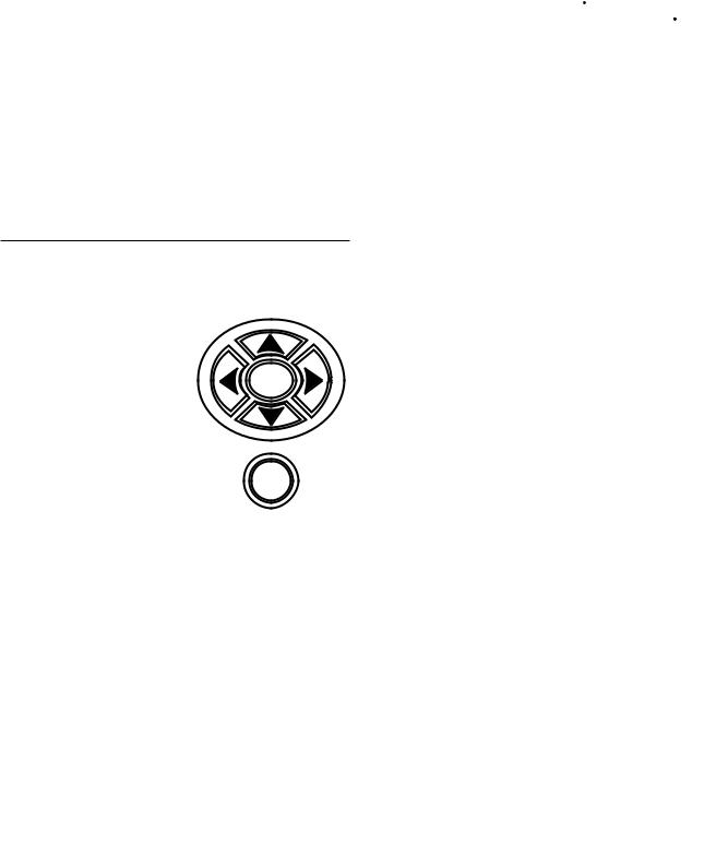
Controls
Navigation Keys
Use the ET90000 timer’s navigation keys to scroll through the display screens, make selections, and enter variables.
• Pressing the up, down, left, or right keys moves
the highlight on the display.
• Pressing ENTER accepts your selection and advances to the next screen.
• Pressing ESC cancels the screen selection and
returns you to the previous screen. (Pressing ESC several times returns you to the STATUS screen.)
USB Port
The ET90000 is equipped with a hi-speed USB 2.0 port for transferring updates and programs. Port functions are:
•transferring schedule programs
•updating the firmware
Manual ON/OFF Keys
The ET90000 unit has a manual ON/OFF key for each circuit in the system. Each key manually overrides the associated circuit, turning the circuit OFF if it is ON and ON if it is OFF. The condition of each circuit displays on the default STATUS SCREEN. 01 E indicates circuit number 1 is OFF and the circuit is ENABLED; 01
 E indicates circuit number 1 is ON and the circuit is ENABLED. If the E is blocked out on the screen, the circuit is DISABLED. Manual overrides can be used but the schedule is not followed. ET90000 systems with 4, 8 or 12 circuits are shipped with all sixteen manual ON/ OFF keys installed. The keys for unused circuits are inactive until you install the proper relay board in the system. Inactive keys are shipped with a plastic cover over them, which you can easily remove when you add an additional relay board.
|
|
|
|
|
|
|
|
|
|
1 |
|
2 |
|
3 |
|
4 |
|
|
ON/OFF |
|
ON/OFF |
|
ON/OFF |
|
ON/OFF |
|
|
|
|
|
|
|
|||
|
5 |
|
6 |
|
7 |
|
8 |
|
|
ON/OFF |
|
ON/OFF |
|
ON/OFF |
|
ON/OFF |
|
|
|
|
|
|
|
|||
|
9 |
|
10 |
|
11 |
|
12 |
|
|
ON/OFF |
|
ON/OFF |
|
ON/OFF |
|
ON/OFF |
|
|
|
|
|
|
|
|||
|
13 |
|
14 |
|
15 |
|
16 |
|
|
ON/OFF |
|
ON/OFF |
|
ON/OFF |
|
ON/OFF |
|
|
|
|
|
|
|
|
|
|
Figure 5: 16-Circuit System ON/OFF Keys
ET90000 Series Electronic Timer |
9 |
|

Programming
Program the ET90000-series electronic timer using the navigation keys (see Figure 4). Some of the inputs you program are simple choices: yes/no, enable/disable, etc.; others involve inputting variables in alpha-numeric characters.
Initial Setup
From the STATUS screen, press ENTER. Use the navigation keys to:
1.Choose INITIAL SETUP.
2.Input the current
date. |
STATUS |
TIMESWITCH |
|
3. Input the correct |
01 E 02 |
E |
|
time (choose 12- |
|||
|
|
||
HOUR, example: |
7/14/11 |
2:20 PM |
|
2:20 PM; or 24- |
|||
|
|
||
HOUR, example: |
|
|
|
|
|
14 hours, 20 minutes).
4.Choose whether you would like the ET90000-series timer to update the time automatically for daylight saving time.
5.Select your time zone.
Programming Events
After you have set up the ET90000-series timer initially, you can program an “event.” An event is something you would like the device to control, such as turning ON lights or turning OFF an alarm.
1.Choose Specific or Relative Date
To program an event, first choose whether you would like your event to occur on a specific or relative date. Program a specific date by choosing the month and day; program a relative date by choosing a date such as the 2nd week of January, or the 10th day of each month.
Available Options: |
|
|
1st-31st |
Mon-Sun |
Jan-Dec |
Each |
Week |
Year |
Last |
Weekday |
Month |
First |
Weekend |
|
|
Day |
|
2.Specify Time
Choose a time when you want your event to occur. Or choose astronomic time, which is sunrise or sunset,
plus or minus a variable number of minutes
(up to ±120), per your requirements.
EVENT 1
TIME TYPE: ASTRO
SUNRISE |
+33 MINS |
ADJUSTMENT |
3.Circuit Type
For your event, choose whether you would like the ET90000-series electronic timer to turn your application ON or OFF, then choose whether the circuit will have a fixed ON or a pulse ON.
Fixed means a steady current. Pulse means a steady current which is ON for a specified time (input hours, minutes, and seconds of pulse) and then turns OFF.
4.Name Your Event
You can choose to give your event a name, such as S LIGHTS or PUMP 1. Enter the name (up to 10
characters) using the |
|
|
|
|
alpha-numeric display. |
NAME: |
EVENT 1 |
|
|
The ET90000 system |
|
|
ABCDEFGHIJKLM |
|
chooses a name for |
|
NOPQUSTUVWYXZ |
||
you if you do not name |
|
012345678 /-: |
||
your event, for example |
DEL |
|
|
ACCEPT |
Event 1. |
|
|
||
5.Determine Circuit Control
After naming your event, select which circuit(s) the event controls. Select as few as one circuit, or as many as 16 circuits on the large capacity device. (Note: Up to 32 external circuits will be available in the future.)
6.Program Holidays
If your event runs during times where there are one or more holidays, which may supplant normal event times and dates, you must program this information into the device.
Similar to programming an event, you name the holiday, set up date and time (in this case, choose the beginning and end of the holiday), then program events into the holiday. Also similar to programming primary event(s), select your circuits and what they do: turn ON with a fixed or pulse duration or turn OFF.
ET90000 Series Electronic Timer |
10 |
|
7.Select Astro(nomic) Zones
If you have previously programmed an event or a holiday based on astronomic time, you must select an astronomic zone after you have programmed in all of your variables, events, and holidays. Select from the following regions:
• |
USA STATES |
SELECT ASTRO ZONE |
|||
COUNTRY |
|
|
|||
• |
MEXICO |
|
|
||
UNITED STATES |
|||||
• |
CANADA |
|
|
||
COUNTRY LOCATION |
|||||
• |
USA |
||||
|
TERRITORIES |
|
ILLINOIS |
||
|
LOCATION QUADRANT |
||||
|
|
||||
Then select the |
|
CENTER |
|||
appropriate COUNTRY |
|
|
|
||
LOCATION and LOCATION QUADRANT.
8.Review Your Event
After you finish programming your events, you can choose YES to review it. Review the program by circuit, by event (ALL, HOLIDAY, or RELATIVE) and by specific date. If the event requires changes, press ENTER with the event highlighted to proceed directly to Advanced Options. You can also edit or change your event from ADVANCED OPTIONS on the SETUP screen.
Tips on Planning Events
Depending on how complex your circuits are, you may prefer to plan your events before programming using a table similar to the one at the right.
EVENTS
|
|
|
|
Type: |
|
Event |
Effective |
Start |
ON/OFF |
Circuit(s) |
Name |
Days |
Time |
FIXED/PULSE |
|
|
|
|
|
|
|
|
|
|
|
|
|
|
|
|
|
|
|
|
|
|
|
|
|
|
|
|
|
|
|
|
|
|
|
HOLIDAYS
|
|
|
|
Type: |
|
Name of |
Begin |
End |
ON/OFF |
Circuit(s) |
Holiday |
Date |
Date |
FIXED/PULSE |
|
|
|
|
|
|
|
|
|
|
|
|
|
|
|
|
|
|
|
|
ET90000 Series Electronic Timer |
11 |
|
ADVANCED OPTIONS
|
ENTER |
|
|
DATE/TIME CONFIG |
|
|
DATE |
|
|
TIME |
|
|
DST |
|
|
ASTRO |
|
SYSTEM CONFIG |
|
|
REVIEW MODE |
|
|
PROG COPY/RESTORE |
|
|
PASSWORD SETUP |
|
|
EDIT SYSTEM NAME |
|
|
NETWORK SETUP |
|
|
FIRMWARE UPDATE |
|
|
RESET TO FAC DEFAULT |
|
|
EVENT CONFIG |
|
|
ADD EVENT |
HOLIDAY CONFIG |
|
MODIFY EVENT |
||
ADD HOLIDAY |
||
DELETE EVENT |
||
MODIFY HOLIDAY |
||
|
||
|
DELETE HOLIDAY |
CIRCUIT CONFIG
EDIT CKT NAME
ENABLE CKT EVENTS
MANUAL ACTIVATE MODE
EXTERNAL OVERRIDE
ZONE CONFIG
ADD ZONE
MODIFY ZONE
DELETE ZONE
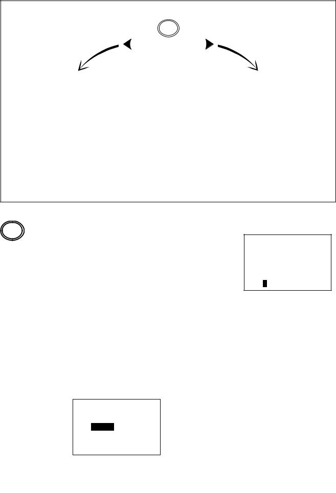
The con guration screens can be navigated using the right or left keys. The accompanying instructions are presented based on a right-key sequence.
ENTER
Advanced Options
Use Advanced Options to edit already-existing programming, configure circuits and zones, and set up your system.
From the STATUS screen, press ENTER and navigate to ADVANCED OPTIONS. Press ENTER to access DATE, TIME, DST, or ASTRO on the DATE/TIME CONFIG screen.
Date
Press ENTER to correct the date.
Time
Press ENTER to change the current time (hours, minutes, AM or PM) or the display mode for the time (12 HOUR AM/PM or 24 HOUR).
DST (Daylight Saving Time)
Press ENTER to enable/disable DST, set the DST time zone, and set up effective dates (start and end date of DST).
DT.DST.EFF—DATES
START DATE (SUN): FOURTH WK OF FEB END DATE (SUN): FIRST WK OF OCT
Astro
From ASTRO, you can define an Astronomic zone (country, location in country, and quadrant location). Also, if you need to adjust the time of the
astronomic zone, you can do so against
the “calculated time” from the ASTRO ADJUSTMENT screen.
ET90000 Series Electronic Timer |
12 |
|

 CIRCUIT CONFIG(uration)
When you press the right key from TIME, DATE, DST, or ASTRO, you have the following options under CIRCUIT CONFIG:
•EDIT CKT (circuit) NAME
•ENABLE CKT EVENTS
•MANUAL ACTIVATE MODE
•EXTERNAL OVERRIDE
Each relay or output is defined as a circuit. Each circuit can be independently configured using the following options.
1.EDIT CKT NAME
Enter or change the name of the circuit(s). First select the circuit you wish to change, then use the keypad to enter or change the name (up to 10 characters; default name is CIRCUIT 1, CIRCUIT 2, etc.).
2.ENABLE CKT EVENTS
When you enable a circuit, it adheres to the scheduled events. However, events do not
turn a disabled circuit ON or OFF but you can
still control disabled circuits manually via pushbuttons or
overrides. Add or remove the checkmark to enable/ disable the circuit.
3.MANUAL ACTIVATE MODE
This determines how the relays are controlled. If FIXED, a pushbutton toggles the circuit ON and OFF normally. If PULSE, after you turn the circuit on manually, the circuit automatically turns OFF when the pulse duration expires. (Note: You can always control circuits manually via the pushbuttons.) To activate:
A.Select the circuit you would like to control.
B.Choose FIXED or PULSE.
C.If PULSE, input duration.
4.EXTERNAL OVERRIDE
You can use external |
|
|
|
remote override |
CIRCUIT . OVERRIDE |
||
switches to control |
|
OVERRIDE 1 |
|
circuits. 1 and 2 |
|
SELECT OVERRIDE |
|
circuit models have |
|
ACTIVATE MODE |
|
two overrides; 4 to 16 |
|
FIXED |
|
circuit units have up to |
|
|
|
|
PULSE |
HH: MM: SS |
|
eight overrides. Select |
|
||
|
|
||
which circuits you will |
|
|
00: 01: 00 |
override, which zones,
and whether the override will be fixed or pulse. If pulse, set duration.

 ZONE CONFIG(URATION)
You will use these options to establish and define zones. You can set up a zone and use it to control one or more circuits, including the circuit’s associated events and holidays. For example, you may create Zone A, which is comprised of circuits 1, 3 and 6 that have four events and three holidays, including each event’s and each holiday’s variables such as the dates, times, etc., associated with them.
If events control zones instead of circuits, you can modify the circuits in a zone without changing any events. To configure, press the right key from CIRCUIT CONFIG to land on ZONE CONFIG where your options are:
•ADD ZONE
•MODIFY ZONE
•DELETE ZONE
1.ADD ZONE
To add a zone, press ENTER from ADD ZONE where your choices are:
•ENABLE A ZONE – You establish a zone by enabling it. Disabling a zone causes it to ignore the programmed schedule.
•EDIT ZONE NAME – Here you can give the zone a name (up to 10 characters; default names are ZONE 1, ZONE 2, etc.).
•EDIT ZONE CIRCUIT LIST – Choose the circuit(s) you wish to include in the zone by placing a checkmark next to the circuit(s).
2.MODIFY ZONE
Select the zone you would like to modify, then choose:
•ENABLE – Choose YES or NO.
•EDIT ZONE NAME – Edit the zone’s name (up to 10 characters; default names are ZONE 1, ZONE 2, etc.).
•EDIT ZONE CIRCUIT LIST– Choose the circuit(s) you wish to include in the zone by placing a checkmark next to the circuit(s).
3.DELETE ZONE
Select the zone you would like to delete, then press ENTER.
13 |
ET90000 Series Electronic Timer |


 HOLIDAY CONFIG(URATION)
Press the right key again from ZONE CONFIG to land on HOLIDAY CONFIG where your options are:
•ADD HOLIDAY
•MODIFY HOLIDAY
•DELETE HOLIDAY
1.ADD HOLIDAY
You create a holiday when you:
•ENABLE A HOLIDAY – Establish the holiday by choosing YES or NO.
•EDIT HOLIDAY NAME – Give the holiday a name (up to 10 characters; default names are HOLIDAY 1, HOLIDAY 2, etc.).
•EDIT HOLIDAY DATES – Choose from FIXED or RELATIVE holiday, where fixed is exact first and last days of the holiday (month and day); relative for example, is 1st day = July 4th, length = 3 days.
2.MODIFY HOLIDAY
Select the holiday you would like to enable, change/add name, and/or edit the holiday’s dates (same as above).
•EDIT EVENT DATE/TIME – Input a fixed date (month and day) or a relative date (example, 1st day of each month); input a fixed time (hour and minute) or an astro time (sunrise or sunset, up to
± 120 minutes allowable adjustment).
•CKT/ZONE/HOL LISTS – Select circuit(s), zone(s) and holiday(s) for this event by placing checkmarks.
•EDIT ACTIVATION TYPE – Select activation mode, either FIXED or PULSE. If PULSE, enter duration in hours, minutes, and seconds.
2.MODIFY EVENT
To modify an event, first select the event to modify then change or edit the event under ENABLE EVENT, EDIT EVENT NAME, EDIT EVENT TYPE, EDIT EVENT DATE/ TIME, CKT/ZONE/HOL LISTS, and/or EDIT ACTIVATION TYPE (see above).
3.DELETE EVENT
Choose the event you would like to delete.
3.DELETE HOLIDAY
Choose any holiday(s) you would like to delete from the zone.


 EVENT CONFIG(URATION)
Press the right key again from HOLIDAY CONFIG to land on EVENT CONFIG where your options are:
•ADD EVENT
•MODIFY EVENT
•DELETE EVENT
1.ADD EVENT
You add an event when you:
•ENABLE EVENT – Establish an event by choosing YES or NO.
•EDIT EVENT NAME – Give the event a name (up to 10 characters; default names are EVENT 1, EVENT 2, etc.).
•EDIT EVENT TYPE – Choose whether this event turns a circuit ON or OFF.
System Configuration Options
Press the right key again from EVENT CONFIG to land on SYSTEM CONFIG. Note: From the STATUS screen, you can also press ENTER; navigate to ADVANCED OPTIONS, press ENTER again, then press the left key once.
Your options are:
•REVIEW MODE
•PROG COPY/RESTORE
•PASSWORD SETUP
•EDIT SYSTEM NAME
•NETWORK SETUP
•FIRMWARE UPDATE
•RESET TO FAC DEFAULT
IMPORTANT: Use the ESC key to return to the SYSTEM CONFIG screen after entering these options.
1.REVIEW MODE
In REVIEW MODE, you can examine the parameters for all your events by circuit and date.
ET90000 Series Electronic Timer |
14 |
|

A)PROGRAMMED SCHEDULE
From REVIEW MODE, you land on PROGRAMMED
SCHEDULE. After you choose which circuit’s schedule you would like to review, you land on SELECT EVENT TYPE. From this
screen, select from the following:
•ALL EVENTS
•HOLIDAY EVENTS ONLY
•RELATIVE EVENTS ONLY
Select the date of the event you would like to review and press enter. The screen shows any event scheduled.
B)EVENT LOG
You can also view an EVENT LOG, such as this example. The event log stores the most recent 1,000+ events and can be saved to USB.
EVENT LOG |
12/31/12 |
PARKING L1 |
|
ON |
5:00 PM |
-MANUAL- |
12/31/12 |
OFF |
2:00 PM |
-SERIAL- |
12/31/12 |
ON |
10:00 AM |
2.PROG COPY/RESTORE
Under this function, you can copy or restore a program into the ET90000-series timer from the USB port. To copy a program, insert a USB drive into the port and follow the prompts. To restore a program, select which program you would like to restore from the list on the screen; press ENTER to delete the current schedule and replace it with the saved USB schedule. Note: Backup your schedule to USB in case it is unintentionally modified, reset, etc.
3. PASSWORD SETUP
On this screen, your choices are:
•ENABLE PASSWORD
•CHANGE PASSWORD
In ENABLE PASSWORD, your choices are ENABLED and DISABLED. When you select ENABLED, it means screens are viewable but you must enter the password to change or add information. Choosing DISABLED means no password is necessary to view, change or add information.
To change the password, press CHANGE PASSWORD. After you land on the SYS PSWORD CHANGE screen, key in up to 10 alphanumeric characters; key in again to confirm. Write down password!
Note: If the password is enabled, you can still reset the device to factory defaults.
IMPORTANT: You can reset to factory defaults even if you do not know the password; in fact, this is the only way
to start “from scratch,” and enter a new password, if the password is permanently lost. Always copy the schedule to USB prior to resetting the timer.
4.EDIT SYSTEM NAME
Use this for identification purposes to name your system when networking multiple timers together. Change or edit the system’s name using up to 10 alpha/numeric characters, then press ACCEPT.
5.NETWORK SETUP
In NETWORK SETUP, you can:
•CONFIGURE NETWORK ADDRESS – If you would like to connect to a network, you must configure the network address. ENTER the IP (internet protocol) address, the subnet mask, and the default gateway.
•CONFIGURE REMOTE ADDRESS – To configure a remote address, you must first connect to an Ethernet device (see page 7). Then you can program up to 16 IP addresses.
•REMOTE CONNECT – Follow the prompts to connect to another Ethernet device.
•REMOTE DISCONNECT – First connect to an Ethernet device, then follow prompts.
•TIME SYNC – Sends the time information from the current timer to all timers, so clocks are synchronized. To synchronize timers, first connect to an Ethernet device, then follow the prompts.
6.FIRMWARE UPDaTE
Firmware updates are available at http://www.intermatic.com. To install an update from a flash drive, insert drive into the USB port, then follow the prompts.
7.RESET FaCTORY DEFaulTS
Choose NO or YES. Be certain you want to do this!
IMPORTANT: Copy the schedule to USB prior to resetting the timer. If you reset factory defaults, you lose all custom programming.
15 |
ET90000 Series Electronic Timer |
 Loading...