

Page 1

Intel® 7500, 7510, and 7512
Scalable Memory Buffer
Thermal/Mechanical Design Guidelines
April 2011
Reference Number: 322828-002
Page 2

INFORMATION IN THIS DOCUMENT IS PROVIDED IN CONNECTION WITH INTEL® PRODUCTS. NO LICENSE, EXPRESS OR IMPLIED,
BY ESTOPPEL OR OTHERWISE, TO ANY INTELLECTUAL PROPERTY RIGHTS IS GRANTED BY THIS DOCUMENT. EXCEPT AS
PROVIDED IN INTEL'S TERMS AND CONDITIONS OF SALE FOR SUCH PRODUCTS, INTEL ASSUMES NO LIABILITY WHATSOEVER,
AND INTEL DISCLAIMS ANY EXPRESS OR IMPLIED WARRANTY, RELATING TO SALE AND/OR USE OF INTEL PRODUCTS INCLUDING
LIABILITY OR WARRANTIES RELATING TO FITNESS FOR A PARTICULAR PURPOSE, MERCHANTABILITY, OR INFRINGEMENT OF ANY
PATENT, COPYRIGHT OR OTHER INTELLECTUAL PROPERTY RIGHT. Intel products are not intended for use in medical, life saving,
life sustaining, critical control or safety systems, or in nuclear facility applications.
Intel may make changes to specifications and product descriptions at any time, without notice.
Designers must not rely on the absence or characteristics of any features or instructions marked “reserved” or “undefined.” Intel
reserves these for future definition and shall have no responsibility whatsoever for conflicts or incompatibilities arising from future
changes to them.
The Intel 7500, 7510, and 7512 Scalable Memory Buffer may contain design defects or errors known as errata, which may cause
the product to deviate from published specifications. Current characterized errata are available upon request.
Contact your local Intel sales office or your distributor to obtain the latest specifications and before placing your product order.
Copies of documents which have an order number and are referenced in this document, or other Intel literature may be obtained
by calling 1-800-548-4725 or by visiting Intel's website at http://www.intel.com.
Intel, Xeon, Itanium, and the Intel logo are trademarks of Intel Corporation in the U.S. and other countries.
* Other brands and names may be claimed as the property of others.
Copyright © 2010, Intel Corporation. All rights reserved.
2 Intel® 7500, 7510, and 7512 Scalable Memory Buffer TMDG
Page 3

Contents
1 Introduction ..............................................................................................................7
1.1 Design Flow........................................................................................................7
1.2 Definition of Terms ..............................................................................................8
1.3 Reference Documents ..........................................................................................9
2 Packaging Technology ............................................................................................. 11
2.1 Package Mechanical Requirements.......................................................................13
3 Thermal Specifications ............................................................................................ 15
3.1 Thermal Design Power (TDP) .............................................................................. 15
3.2 Die Case Temperature Specifications.................................................................... 15
4 Thermal Metrology .................................................................................................. 17
4.1 Die Temperature Measurements.......................................................................... 17
4.1.1 Zero Degree Angle Attach Methodology ..................................................... 17
5 Reference Thermal Solution 1.................................................................................. 21
5.1 Operating Environment ...................................................................................... 21
5.1.1 Maximum Fan Speed Assumption ............................................................. 21
5.1.2 Acoustics Fan Speed Assumption.............................................................. 21
5.2 Heatsink Performance........................................................................................ 22
5.3 Mechanical Design Envelope ............................................................................... 23
5.4 Board-Level Components Keepout Dimensions ...................................................... 23
5.5 Tall Torsional Clip Heatsink Thermal Solution Assembly .......................................... 25
5.5.1 Heatsink Orientation............................................................................... 26
5.5.2 Extruded Heatsink Profiles ....................................................................... 26
5.5.3 Mechanical Interface Material................................................................... 27
5.5.4 Thermal Interface Material....................................................................... 27
5.5.5 Heatsink Clip ......................................................................................... 27
5.5.6 Clip Retention Anchors............................................................................ 27
5.6 Reliability Guidelines.......................................................................................... 28
6 Reference Thermal Solution 2.................................................................................. 29
6.1 Operating Environment ...................................................................................... 29
6.1.1 Maximum Fan Speed Assumption ............................................................. 29
6.1.2 Acoustics Fan Speed Assumption.............................................................. 29
6.2 Heatsink Performance........................................................................................ 30
6.3 Mechanical Design Envelope ............................................................................... 31
6.4 Board-Level Components Keepout Dimensions ...................................................... 31
6.5 Short Torsional Clip Heatsink Thermal Solution Assembly........................................ 31
6.5.1 Heatsink Orientation............................................................................... 32
6.5.2 Extruded Heatsink Profiles ....................................................................... 32
6.5.3 Mechanical Interface Material................................................................... 33
6.5.4 Thermal Interface Material....................................................................... 33
6.5.5 Heatsink Clip ......................................................................................... 33
6.5.6 Clip Retention Anchors............................................................................ 33
6.6 Reliability Guidelines.......................................................................................... 33
A Thermal Solution Component Suppliers ................................................................... 35
A.1 Tall Torsional Clip Heatsink Thermal Solution ........................................................ 35
A.2 Short Torsional Clip Heatsink Thermal Solution...................................................... 36
B Mechanical Drawings............................................................................................... 37
Intel® 7500, 7510, and 7512 Scalable Memory Buffer TMDG 3
Page 4

Figures
1-1 Thermal Design Process....................................................................................... 8
2-1 Scalable Memory Buffer Package Dimensions (Top View).........................................11
2-2 Scalable Memory Buffer Package Dimensions (Side View)........................................11
2-3 Scalable Memory Buffer Package Dimensions (Bottom View)....................................12
4-1 Thermal Solution Decision Flowchart ....................................................................18
4-2 Zero Degree Angle Attach Heatsink Modifications ...................................................18
4-3 Zero Degree Angle Attach Methodology (Top View) ................................................19
5-1 Tall Torsional Clip Heatsink Measured Thermal Performance Versus
Approach Velocity ..............................................................................................22
5-2 Tall Torsional Clip Heatsink Volumetric Envelope for the
Intel 7500 Scalable Memory Buffer.......................................................................23
5-3 Tall Torsional Clip Heatsink Board Component Keepout ...........................................24
5-4 Retention Mechanism Component Keepout Zones...................................................25
5-5 Tall Torsional Clip Heatsink Assembly ...................................................................26
5-6 Tall Torsional Clip Heatsink Extrusion Profile..........................................................26
5-7 Anchors for Tall and Short Heatsink Retention .......................................................28
6-1 Short Torsional Clip Heatsink Measured Thermal Performance Versus
Approach Velocity ..............................................................................................30
6-2 Short Torsional Clip Heatsink Volumetric Envelope .................................................31
6-3 Short Torsional Clip Heatsink Assembly.................................................................32
6-4 Short Torsional Clip Heatsink Extrusion Profile .......................................................32
B-1 Tall Torsional Clip Heatsink Assembly Orientation A Drawing....................................38
B-2 Tall Torsional Clip Heatsink Assembly Orientation B Drawing....................................39
B-3 Tall Torsional Clip Heatsink Drawing.....................................................................40
B-4 Tall/Short Torsional Clip Heatsink Clip Drawing ......................................................41
B-5 Short Torsional Clip Heatsink Assembly Orientation A Drawing .................................42
B-6 Short Torsional Clip Heatsink Assembly Orientation B Drawing .................................43
B-7 Short Torsional Clip Heatsink Assembly.................................................................44
Tables
3-1 Intel Scalable Memory Buffer Thermal Design Power...............................................15
3-2 Intel 7500 Scalable Memory Buffer Thermal Specification........................................16
5-1 Honeywell PCM45 F* TIM Performance as a Function of Attach Pressure....................27
5-2 Anchor Bend Angle and Maximum Pullout Force as a Function of Board Thickness.......28
5-3 Reliability Guidelines ..........................................................................................28
B-1 Mechanical Drawing List......................................................................................37
4 Intel® 7500, 7510, and 7512 Scalable Memory Buffer TMDG
Page 5
Revision History
Revision Description Date
001 Initial Release April 2010
• Added product specifications for Intel 7510 and 7512 Scalable Memory
buffer
• Replaced reference to ‘Intel 7500 Scalable Memory Buffer’ with
‘components’ where guidance also applies to Intel 7510 and 7512 Scalable
002
Memory Buffer. See change bars throughout document.
• Section 2: Revised the figures title
• Section 3.1: Reworded the paragraph
• Table 3-1: Updated the table
• Table 3-2: Added note 6
§
April 2011
Intel® 7500, 7510, and 7512 Scalable Memory Buffer TMDG 5
Page 6

6 Intel® 7500, 7510, and 7512 Scalable Memory Buffer TMDG
Page 7

Introduction
1 Introduction
As the complexity of computer systems increases, so do the power dissipation
requirements. Care must be taken to ensure that the additional power is properly
dissipated. Typical methods to improve heat dissipation include selective use of
ducting, and/or passive heatsinks.
Note: This document addresses thermal design and specifications for the Intel® 7500, 7510,
and 7512 Scalable Memory Buffer. Information provided in this document is intended
only for use with these products. Unless otherwise specified, specification and guidance
provided in this document applies to products identified above. In this document the
term ‘component’ refer to Intel 7500, 7510, and 7512 Scalable Memory Buffer
components unless other wise identified.
The goals of this document are to:
• Outline the mechanical operating limits and specifications for the Intel® 7500,
7510, and 7512 Scalable Memory Buffer (MB).
• Outline reference TDP specifications for the Intel 7500, 7510, and 7512 Scalable
Memory Buffer specific to that of Intel® Xeon® processor 7500 series-based
platform and Intel® Itanium® processor 9300 series-based platform.
• Describe reference thermal solutions that meet the specifications of the Intel 7500,
7510, and 7512 Scalable Memory Buffer.
Properly designed thermal solutions provide adequate cooling to maintain the
component die temperature at or below thermal specifications. This is accomplished by
providing a low local-ambient temperature, ensuring adequate local airflow, and
minimizing the die to local-ambient thermal resistance. By maintaining the memory
buffer component die temperature at or below the specified limits, a system designer
can ensure the proper functionality, performance, and reliability of the chipset.
Operation outside the functional limits can degrade system performance and may
cause permanent changes in the operating characteristics of the component.
The simplest and most cost-effective method to improve the inherent system cooling
characteristics is through proper chassis design and placement of fans, vents, and
ducts. When additional cooling is required, component thermal solutions may be
implemented in conjunction with system thermal solutions. The size of the fan or
heatsink can be varied to balance size and space constraints with acoustic noise.
1.1 Design Flow
To develop a reliable, cost-effective thermal solution, several tools have been provided
to the system designer. Figure 1-1 illustrates the design process implicit to this
document and the tools appropriate for each step.
Intel® 7500, 7510, and 7512 Scalable Memory Buffer TMDG 7
Page 8
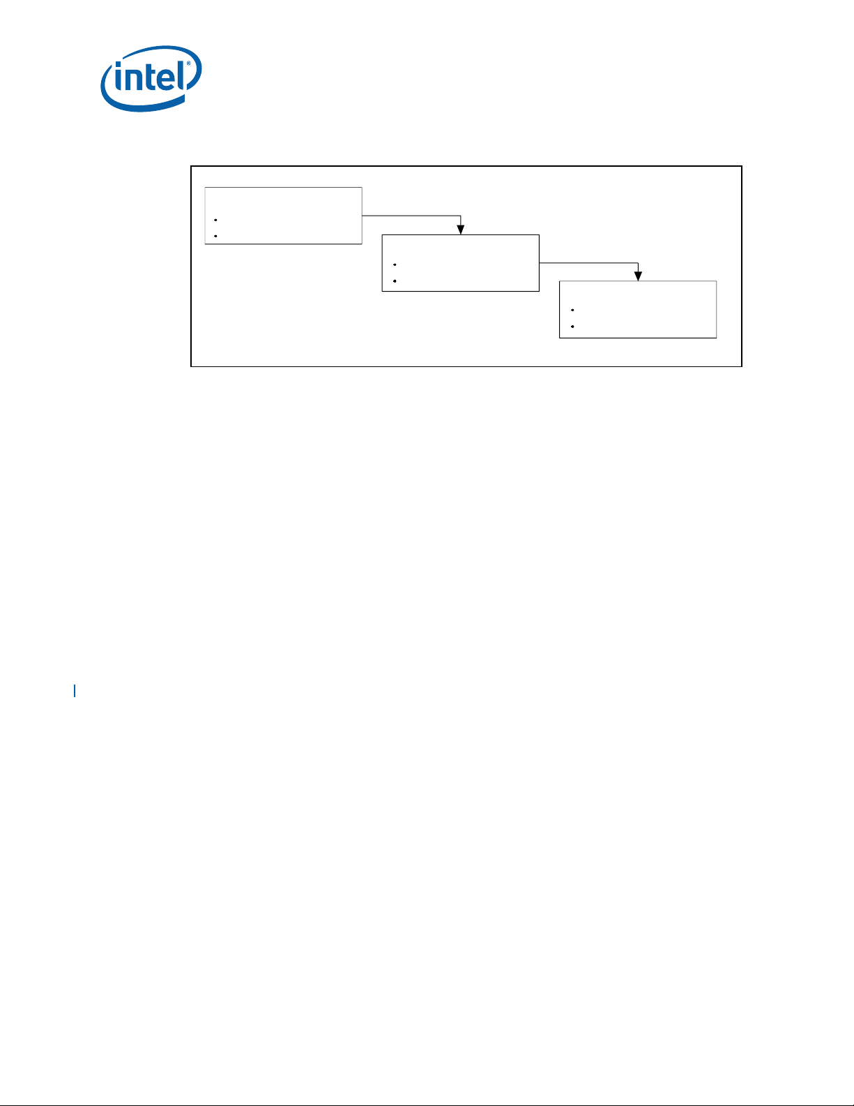
Figure 1-1. Thermal Design Process
Step 1 : T herm al
Sim ulation
The rm al M od el
The rm al M od el U se r's G uide
Step 2 : H ea tsink S elec tion
1.2 Definition of Terms
FC-BGA Flip Chip Ball Grid Array. A package type defined by a plastic substrate where
a die is mounted using an underfill C4 (Controlled Collapse Chip Connection)
attach style. The primary electrical interface is an array of solder balls
attached to the substrate opposite the die. Note that the device arrives at
the customer with solder balls attached.
BLT Bond Line Thickness. Final settled thickness of the thermal interface
material after installation of heatsink.
MB Intel 7500 Scalable Memory Buffer. The chipset component responsible for
handling Intel® Scalable Memory Interconnect (Intel®SMI) channel and
memory requests to and from the local DIMM. All memory control for the
DRAM resides in the host, including memory request initiation, timing,
refresh, scrubbing, sparing, configuration access, and power management.
T
case_max
T
case_min
TDP Thermal design power: Thermal solutions should be designed to dissipate
Maximum die operating temperature, and is measured at the geometric
center of the top of the die.
Minimum die operating temperature, and is measured at the geometric
center of the top of the die.
this target power level. TDP is not the maximum power that the chipset can
dissipate.
Introduction
The rm al R eferen ce
Me cha nical R efe renc e
S tep 3 : T herm al V alida tion
The rm al T es ting S oftware
So ftw a re Us e r's Gu ide
8 Intel® 7500, 7510, and 7512 Scalable Memory Buffer TMDG
Page 9

Introduction
1.3 Reference Documents
The reader of this specification should also be familiar with material and concepts
presented in the following documents:
• Intel® 7500, 7510, and 7512 Scalable Memory Buffer Datasheet
• Various system thermal design suggestions (http://www.formfactors.org)
§
Intel® 7500, 7510, and 7512 Scalable Memory Buffer TMDG 9
Page 10

Introduction
10 Intel® 7500, 7510, and 7512 Scalable Memory Buffer TMDG
Page 11
Packaging Technology
19.50mm.
2 Packaging Technology
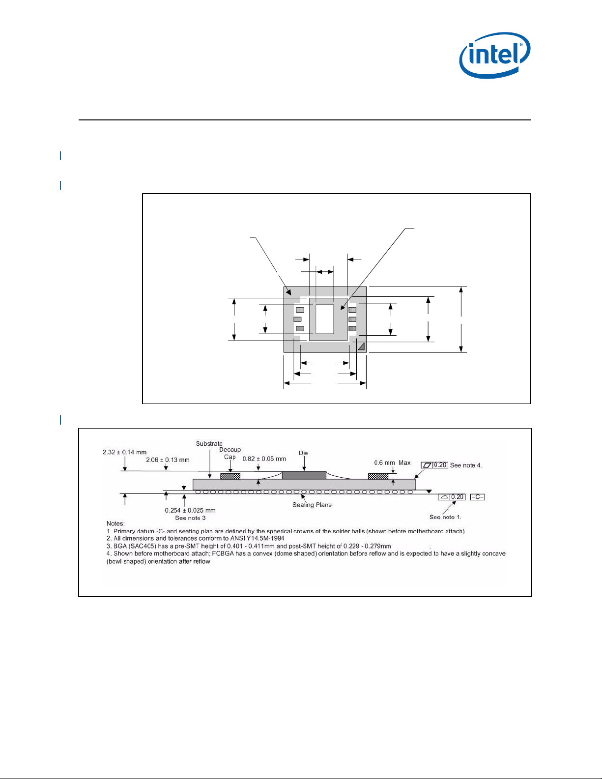
The Intel 7500, 7510, and 7512 Scalable Memory Buffer components uses a 24.5 mm x
19.5 mm, 12-layer FC-BGA package (see Figure 2-1, Figure 2-2 and Figure 2-3).
Figure 2-1. Scalable Memory Buffer Package Dimensions (Top View)
Handling
Exclusion
Area
5.30mm.
11.30mm.
Die
Keepout
Area
8.50mm.12.50mm.
Die
14.50mm.
18.50mm.
24.50mm.
9.50mm.
13.50mm.
Figure 2-2. Scalable Memory Buffer Package Dimensions (Side View)
Intel® 7500, 7510, and 7512 Scalable Memory Buffer TMDG 11
Page 12
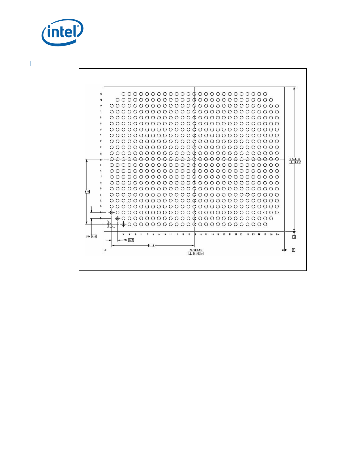
Figure 2-3. Scalable Memory Buffer Package Dimensions (Bottom View)
Packaging Technology
Notes:
1. All dimensions are in millimeters.
2. All dimensions are tolerances confirm to ANSI Y14.5M-1994.
12 Intel® 7500, 7510, and 7512 Scalable Memory Buffer TMDG
Page 13

Packaging Technology
2.1 Package Mechanical Requirements
The component package has an exposed bare die which is capable of sustaining a
maximum static normal load of 15 lbf. The package is NOT capable of sustaining a
dynamic or static compressive load applied to any edge of the bare die. These
mechanical load limits must not be exceeded during heatsink installation, mechanical
stress testing, standard shipping conditions and/or any other use condition.
Notes:
1. The heatsink attach solutions must not include continuous stress onto the chipset
package with the exception of a uniform load to maintain the heatsink-to-package
thermal interface.
2. These specifications apply to uniform compressive loading in a direction
perpendicular to the bare die top surface.
3. These specifications are based on limited testing for design characterization.
Loading limits are for the package only.
§
Intel® 7500, 7510, and 7512 Scalable Memory Buffer TMDG 13
Page 14

Packaging Technology
14 Intel® 7500, 7510, and 7512 Scalable Memory Buffer TMDG
Page 15

Thermal Specifications
3 Thermal Specifications
3.1 Thermal Design Power (TDP)
Analysis indicates that real applications are unlikely to cause the component to
consume maximum power dissipation for sustained time periods. Therefore, in order to
arrive at a more realistic power level for thermal design purposes, Intel characterizes
power consumption based on known platform benchmark applications. The resulting
power consumption is referred to as the Thermal Design Power (TDP). Hence, TDP is
the design target for the thermal solution. TDP is not the maximum power that the
memory buffer component can dissipate.
For TDP specifications, see Table 3-1 for the Intel 7500, 7510, and 7512 Scalable
Memory Buffer components. FC-BGA packages have poor heat transfer capability into
the board, and have minimal thermal capability without a thermal solution. Intel
recommends that system designers plan for a heatsink when using an Intel 7500
Scalable Memory Buffer component.
3.2 Die Case Temperature Specifications
To ensure proper operation and reliability of the component, the die temperature must
comply with the thermal profile as specified in Table 3-2. System and/or component
level thermal solutions are required to maintain these temperature specifications. Refer
to Chapter 4, “Thermal Metrology,” for guidelines on accurately measuring package die
temperatures.
Table 3-1. Intel® Scalable Memory Buffer Thermal Design Power
RDIMM LVDIMM
Component
Intel® 7500
Scalable
Memory Buffer
Intel® 7510
Memory Buffer
Notes:
1. These specifications are based on preliminary post-silicon measurement and subject to change.
2. Maximum of four (4) memory buffers are supported per processor socket. Additionally, Each memory buffer can support up to
4 memory DIMMs. See specific memory buffer datasheet or electronic design specification documents for additional
information.
3. TDP values for the memory buffers are based on loading Quad Rank, two DIMM per Channel per Intel 7510/7512 Scalable
Memory Buffer.
4. When Intel 7510/7512 Scalable Memory Buffer is used with the Intel® Xeon® processor 7500/6500 series, only the Intel
7500 Scalable Memory Buffer feature set is supported and validated; no validation, support, or warranty of LV-DIMMs with
Intel 7510/7512 Scalable Memory Buffer on Intel® Xeon® processor 7500 series-based platforms.
5. Intel 7510/7512 Scalable Memory Buffer idle power assumption is with the processor C3E power saving mode enabled.
Standard
/
Low Power
NA 4 Socket, 130 W Intel
NA 4 Socket, 185 W Intel
Standard 4 Socket, 130 W Intel
Platform Configurations TDP_max3Idle Power3TDP_Max3Idle Power
Xeon® processor 7500 series
Itanium® processor 9300
series
Xeon® Processor 7500 Series
®
®
®
10 W 7 W — —
10 W 7 W — —
8.7 W 3 W NA
4
NA
3
4
Intel® 7500, 7510, and 7512 Scalable Memory Buffer TMDG 15
Page 16

Table 3-2. Intel® 7500 Scalable Memory Buffer Thermal Specification
Parameter Value Note
Tcase_max 92°C 1,2,6
Tcase_min 5°C 1,2,3,4,5,6
Tcontrol 87°C 1,2,3,4,5,6
Notes:
1. Tcase_min and Tcase_max represent the operating temperature range of the memory buffer. For additional
information on memory buffer thermal specifications Refer to the Intel® 7500,7510, and 7512 Scalable
Memory Buffer Datasheet.
2. Refer to the Intel® 7500, 7510, 7512 Scalable Memory Buffer Datasheet for thermal management
mechanism and Tcontrol usage.
3. The Tcontrol threshold value to be compared against the thermal sensor reading.
4. When the thermal sensor reading is less than the Tcontrol value, system can run under acoustic condition.
5. When the thermal sensor reading is larger than the Tcontrol value, the fan speed must increase as
necessary to maintain the sensor temperature at or below the Tcontrol value.
6. These specifications apply to Intel 7500, 7510, and 7512 Scalable Memory Buffer.
§
Thermal Specifications
16 Intel® 7500, 7510, and 7512 Scalable Memory Buffer TMDG
Page 17

Thermal Metrology
4 Thermal Metrology
The system designer must make temperature measurements to accurately determine
the thermal performance of the system. Intel has established guidelines for proper
techniques to measure the component die temperatures. Section 4.1 provides
guidelines on how to accurately measure the Intel 7500 Scalable Memory Buffer die
temperatures.
4.1 Die Temperature Measurements
To ensure functionality and reliability, the component T
between the maximum/minimum operating range of the temperature specification as
noted in Table 3-1. The surface temperature at the geometric center of the die
corresponds to T
temperature measurement.
Temperature differences between the temperature of a surface and the surrounding
local ambient air can introduce errors in the measurements. The measurement errors
could be due to a poor thermal contact between the thermocouple junction and the
surface of the package, heat loss by radiation and/or convection, conduction through
thermocouple leads, and/or contact between the thermocouple cement and the
heatsink base (if a heatsink is used). For maximum measurement accuracy, only the 0°
thermocouple attach approach is recommended.
. Measuring T
case
requires special care to ensure an accurate
case
case
4.1.1 Zero Degree Angle Attach Methodology
1. Mill a 3.3 mm (0.13 in.) diameter and 1.5 mm (0.06 in.) deep hole centered on the
bottom of the heatsink base.
2. Mill a 1.3 mm (0.05 in.) wide and 0.5 mm (0.02 in.) deep slot from the centered
hole to one edge of the heatsink. The slot should be parallel to the heatsink fins
(see Figure 4-2).
3. Attach thermal interface material (TIM) to the bottom of the heatsink base.
4. Cut out portions of the TIM to make room for the thermocouple wire and bead. The
cutouts should match the slot and hole milled into the heatsink base.
5. Attach a 36 gauge or smaller calibrated K-type thermocouple bead or junction to
the center of the top surface of the die using a high thermal conductivity cement.
During this step, ensure no contact is present between the thermocouple cement
and the heatsink base because any contact will affect the thermocouple reading.
It is critical that the thermocouple bead makes contact with the die (see
Figure 4-3).
6. Attach heatsink assembly to the component and route thermocouple wires out
through the milled slot.
must be maintained at or
Intel® 7500, 7510, 7512 Scalable Memory Buffer TMDG 17
Page 18

Figure 4-1. Thermal Solution Decision Flowchart
Start
Attach
Attach device
to board
using normal
reflow
process.
thermocouples
using recommended
metrology. Setup
the system in the
desired
configuration.
Run the Power
program and
monitor the
device die
temperature.
Tdie >
Specification?
Thermal Metrology
No
End
Select
Heatsink
Heatsink
Required
Figure 4-2. Zero Degree Angle Attach Heatsink Modifications
Note: Not to scale.
Yes
18 Intel® 7500, 7510, 7512 Scalable Memory Buffer TMDG
Page 19

Thermal Metrology
Thermocouple Bead
Figure 4-3. Zero Degree Angle Attach Methodology (Top View)
Die
Thermocouple
Wire
Substrate
Note: Not to scale.
Cement +
§
Intel® 7500, 7510, 7512 Scalable Memory Buffer TMDG 19
Page 20

Thermal Metrology
20 Intel® 7500, 7510, 7512 Scalable Memory Buffer TMDG
Page 21

Reference Thermal Solution 1
5 Reference Thermal Solution 1
Intel has developed two different reference thermal solutions to meet the cooling needs
of the components under operating environments and specifications defined in this
document. This chapter describes the overall requirements for the tall torsional clip
heatsink reference thermal solution, including critical-to-function dimensions, operating
environment, and validation criteria. Other chipset components may or may not need
attached thermal solutions depending on specific system local-ambient operating
conditions.
This reference thermal solution allows for the attachment of the torsional clip in one of
two different orientations: A and B.
5.1 Operating Environment
The tall reference thermal solution was designed assuming both a max fan speed
condition and an acoustic fan speed condition. The thermal designer must carefully
select the location to measure airflow to obtain an accurate estimate.
5.1.1 Maximum Fan Speed Assumption
• Local-ambient temperature: 56.3°C (based on 35°C external-ambient temperature
at sea level)
• Minimum airflow velocity through the cross-section of the heatsink fins: 2.2 m/s
Note: External-ambient refers to the environment external to the system.
5.1.2 Acoustics Fan Speed Assumption
• Local-ambient temperature: 54.9°C (based on 25°C external-ambient temperature
at sea level)
• Minimum airflow velocity through the cross-section of the heatsink fins: > 0.8 m/s
Note: External-ambient refers to the environment external to the system.
Intel® 7500, 7510, and 7512 Scalable Memory Buffer TMDG 21
Page 22

5.2 Heatsink Performance
Figure 5-1 depicts the simulated thermal performance of the reference thermal solution
versus approach air velocity. Since this data was modeled at sea level, a correction
factor would be required to estimate thermal performance at other altitudes.
The following equation can be used to determine the thermal solution performance at a
given altitude:
Reference Thermal Solution 1
–
alt
ca
Q
=
+
alt
------
o
, and can be obtained from Figure 5-1.
Q - “velocity through heatsink fin area (m/s)”. Velocity is the value on X axis of
Figure 5-1.
- Air density at given altitude
alt
- Air density at sea level
0
Figure 5-1. Tall Torsional Clip Heatsink Measured Thermal Performance Versus
Approach Velocity
–
22 Intel® 7500, 7510, and 7512 Scalable Memory Buffer TMDG
Page 23

Reference Thermal Solution 1
5.3 Mechanical Design Envelope
While each design may have unique mechanical volume and height restrictions or
implementation requirements, the height, width, and depth constraints typically placed
on the component thermal solution are shown in Figure 5-2.
Any motherboard components placed between the heatsink and motherboard cannot
exceed 2 mm (0.07 in.) in height when using heatsinks that extend beyond the
component reference heatsink envelope shown in Figure 5-2.
Figure 5-2. Tall Torsional Clip Heatsink Volumetric Envelope for the
Intel® 7500 Scalable Memory Buffer
Note: All heights shown are maximum values.
5.4 Board-Level Components Keepout Dimensions
The location of hole patterns and keepout zones for the reference thermal solution are
shown in Figure 5-3 and Figure 5-4.
Intel® 7500, 7510, and 7512 Scalable Memory Buffer TMDG 23
Page 24

Figure 5-3. Tall Torsional Clip Heatsink Board Component Keepout
Reference Thermal Solution 1
24 Intel® 7500, 7510, and 7512 Scalable Memory Buffer TMDG
Page 25

Reference Thermal Solution 1
Figure 5-4. Retention Mechanism Component Keepout Zones
5.5 Tall Torsional Clip Heatsink Thermal Solution
Assembly
The reference thermal solution for the components is a passive extruded heatsink with
thermal interface. It is attached using a clip with each end hooked through an anchor
soldered to the board. Figure 5-5 shows the reference thermal solution assembly and
associated components.
Full mechanical drawings of the thermal solution assembly and the heatsink clip are
provided in Appendix B. Appendix A contains vendor information for each thermal
solution component.
Intel® 7500, 7510, and 7512 Scalable Memory Buffer TMDG 25
Page 26

Figure 5-5. Tall Torsional Clip Heatsink Assembly
Reference Thermal Solution 1
Clip Orientation A
5.5.1 Heatsink Orientation
Since this solution is based on a unidirectional heatsink, mean airflow direction must be
aligned with the direction of the heatsink fins.
5.5.2 Extruded Heatsink Profiles
The reference thermal solution uses an extruded heatsink for cooling the components.
Figure 5-6 shows the heatsink profile. Appendix A lists a supplier for this extruded
heatsink. Other heatsinks with similar dimensions and increased thermal performance
may be available. Full mechanical drawings of this heatsink are provided in Appendix B.
Figure 5-6. Tall Torsional Clip Heatsink Extrusion Profile
Clip Orientation B
26 Intel® 7500, 7510, and 7512 Scalable Memory Buffer TMDG
Page 27

Reference Thermal Solution 1
5.5.3 Mechanical Interface Material
There is no mechanical interface material associated with this reference solution.
5.5.4 Thermal Interface Material
A thermal interface material (TIM) provides improved conductivity between the die and
heatsink. The reference thermal solution uses Honeywell PCM45 F*, 0.25 mm (0.010
in.) thick, 15 mm x 15 mm (0.6 in. x 0.6 in.) square.
Note: Unflowed or “dry” Honeywell PCM45 F* has a material thickness of 0.010 in. The flowed
or “wet” Honeywell PCM45 F has a material thickness of ~0.003 in. after it reaches its
phase change temperature.
5.5.4.1 Effect of Pressure on TIM Performance
As mechanical pressure increases on the TIM, the thermal resistance of the TIM
decreases. This phenomenon is due to the decrease of the bond line thickness (BLT).
BLT is the final settled thickness of the thermal interface material after installation of
the heatsink. The effect of pressure on the thermal resistance of the Honeywell
PCM45 F* TIM is shown in Table 5-1.
Intel provides both End of Line and End of Life TIM thermal resistance values for
Honeywell PCM45 F. End of Line and End of Life TIM thermal resistance values are
obtained through measurement on a Test Vehicle similar to the component’s physical
attributes using an extruded aluminum heatsink. The End of Line value represents the
TIM performance post heatsink assembly while the End of Life value is the predicted
TIM performance when the product and TIM reaches its end of life. The heatsink clip
provides enough pressure for the TIM to achieve an End of Line thermal resistance of
0.19°C in2/W and an End of Life thermal resistance of 0.39°C in2/W.
Table 5-1. Honeywell PCM45 F* TIM Performance as a Function of Attach Pressure
2
Pressure on Thermal solution
and package interface (PSI)
40 0.19 0.391
Thermal Resistance (°C × in
End of Line End of Life
)/W
5.5.5 Heatsink Clip
The reference solution uses a wire clip with hooked ends. The hooks attach to wire
anchors to fasten the clip to the board. See Appendix B for a mechanical drawing of the
clip.
5.5.6 Clip Retention Anchors
For Intel 7500, 7510, and 7512 Scalable Memory Buffer-based platforms that have
very limited board space, a clip retention anchor has been developed to minimize the
impact of clip retention on the board. It is based on a standard three-pin jumper and is
soldered to the board like any common through-hole header. A new anchor design is
available with 45° bent leads to increase the anchor attach reliability over time. See
Appendix A for part number and supplier information.
Intel® 7500, 7510, and 7512 Scalable Memory Buffer TMDG 27
Page 28

Reference Thermal Solution 1
Figure 5-7. Anchors for Tall and Short Heatsink Retention
Anchors forces
Anchors forces
contacting points
contacting points
Wave Soldering
Wave Soldering
Junctions
Junctions
Anchors pins
Anchors pins
Table 5-2. Anchor Bend Angle and Maximum Pullout Force as a Function of Board
Thickness
Intel Part
Number
A13494-008
Foxconn Part
Number
HB9703E-DW 0.062 45 10 lbf
HB9703E-M3W 0.085 45 10 lbf
MB Thickness
(Inches)
5.6 Reliability Guidelines
Each motherboard, heatsink and attach combination may vary the mechanical loading
of the component. Based on the end user environment, the user should define the
appropriate reliability test criteria and carefully evaluate the completed assembly prior
to use in high volume. The reference solution is to be mounted to a fully configured
system. Some general recommendations are shown in Table 5-3.
Table 5-3. Reliability Guidelines
[1]
Test
Mechanical Shock 50 g, board level, 11 msec, 3 shocks/axis Visual Check and Electrical Functional Test
Random Vibration 7.3 g, board level, 45 min/axis, 50 Hz to
Temperature Life 85°C, 2000 hours total, check points at
Thermal Cycling -5°C to +70°C, 500 cycles Visual Check
Humidity 85% relative humidity, 55°C, 1000 hours Visual Check
Notes:
1. It is recommended that the above tests be performed on a sample size of at least twelve assemblies from
three lots of material.
2. Additional inspection guidelines may be added at the discretion of the user.
2000 Hz
168, 500, 1000 and 2000 hours
Objective Inspection Guidelines
Anchor Bend
Angle (degrees)
Visual Check and Electrical Functional Test
Visual Check
Max Pullout Force
For Each Anchor
[2]
§
28 Intel® 7500, 7510, and 7512 Scalable Memory Buffer TMDG
Page 29

Reference Thermal Solution 2
6 Reference Thermal Solution 2
Intel has developed two different reference thermal solutions to meet the cooling needs
of the components under operating environments and specifications defined in this
document. This chapter describes the overall requirements for the short torsional clip
heatsink reference thermal solution, including critical-to-function dimensions, operating
environment, and validation criteria. Other chipset components may or may not need
attached thermal solutions depending on specific system local-ambient operating
conditions.
This reference thermal solution allows for the attachment of the torsional clip in one of
two different orientations: A and B.
6.1 Operating Environment
The short reference thermal solution was designed assuming both a max fan speed
condition and an acoustic fan speed condition. The thermal designer must carefully
select the location to measure airflow to obtain an accurate estimate.
6.1.1 Maximum Fan Speed Assumption
• Local-ambient temperature: 56.3°C (based on 35°C external-ambient temperature
at sea level)
• Minimum airflow velocity through the cross-section of the heatsink fins: 3 m/s
Note: External-ambient refers to the environment external to the system.
6.1.2 Acoustics Fan Speed Assumption
• Local-ambient temperature: 54.9°C (based on 25°C external-ambient temperature
at sea level)
• Minimum airflow velocity through the cross-section of the heatsink fins: 2.3 m/s
Note: External-ambient refers to the environment external to the system.
Intel® 7500, 7510, and 7512 Scalable Memory Buffer TMDG 29
Page 30

6.2 Heatsink Performance
Figure 6-1 depicts the simulated thermal performance of the reference thermal solution
versus approach air velocity. Since this data was modeled at sea level, a correction
factor would be required to estimate thermal performance at other altitudes.
The following equation can be used to determine the thermal solution performance at a
given altitude:
Reference Thermal Solution 2
–
alt
ca
Q
=
+
alt
------
o
, and can be obtained from Figure 6-1.
Q - “velocity through heatsink fin area (m/s)”. Velocity is the value on X axis of
Figure 6-1.
- Air density at given altitude
alt
- Air density at sea level
0
Figure 6-1. Short Torsional Clip Heatsink Measured Thermal Performance Versus
Approach Velocity
–
30 Intel® 7500, 7510, and 7512 Scalable Memory Buffer TMDG
Page 31

Reference Thermal Solution 2
6.3 Mechanical Design Envelope
While each design may have unique mechanical volume and height restrictions or
implementation requirements, the height, width, and depth constraints typically placed
on the component thermal solution are shown in Figure 6-2.
Any motherboard components placed between the heatsink and motherboard cannot
exceed 2 mm (0.07 in.) in height when using heatsinks that extend beyond the
reference heatsink envelope shown in Figure 6-2.
Figure 6-2. Short Torsional Clip Heatsink Volumetric Envelope
Note: All heights shown above are maximum values.
6.4 Board-Level Components Keepout Dimensions
This short reference thermal solution has the same components keepout as the tall
reference thermal solution. Refer to Section 5.4 for details.
6.5 Short Torsional Clip Heatsink Thermal Solution
Assembly
The reference thermal solution for components is a passive extruded heatsink with
thermal interface. It is attached using a clip with each end hooked through an anchor
soldered to the board. Figure 6-3 shows the reference thermal solution assembly and
associated components.
Full mechanical drawings of the thermal solution assembly and the heatsink clip are
provided in Appendix B. Appendix A contains vendor information for each thermal
solution component.
Intel® 7500, 7510, and 7512 Scalable Memory Buffer TMDG 31
Page 32

Figure 6-3. Short Torsional Clip Heatsink Assembly
Reference Thermal Solution 2
Clip Orientation A
6.5.1 Heatsink Orientation
Since this solution is based on a unidirectional heatsink, mean airflow direction must be
aligned with the direction of the heatsink fins.
6.5.2 Extruded Heatsink Profiles
The reference thermal solution uses an extruded heatsink for cooling the components.
Figure 6-4 shows the heatsink profile. Appendix A lists a supplier for this extruded
heatsink. Other heatsinks with similar dimensions and increased thermal performance
may be available. Full mechanical drawings of this heatsink are provided in Appendix B.
Figure 6-4. Short Torsional Clip Heatsink Extrusion Profile
Clip Orientation B
32 Intel® 7500, 7510, and 7512 Scalable Memory Buffer TMDG
Page 33

Reference Thermal Solution 2
6.5.3 Mechanical Interface Material
There is no mechanical interface material associated with this reference solution.
6.5.4 Thermal Interface Material
Refer to Section 5.5.4 for details.
6.5.5 Heatsink Clip
Refer to Section 5.5.5 for details.
6.5.6 Clip Retention Anchors
Refer to Section 5.5.6 for details.
6.6 Reliability Guidelines
Refer to Section 5.6 for details.
§
Intel® 7500, 7510, and 7512 Scalable Memory Buffer TMDG 33
Page 34

Reference Thermal Solution 2
34 Intel® 7500, 7510, and 7512 Scalable Memory Buffer TMDG
Page 35

Thermal Solution Component Suppliers
A Thermal Solution Component
Suppliers
A.1 Tall Torsional Clip Heatsink Thermal Solution
Part
Heatsink Assembly includes:
• Heatsink
• Thermal Interface Material
• Torsional Clip
Heatsink (26.0 x 26.0 x 28.0 mm)
Thermal Interface
(PCM45F)
Heatsink Attach Clip
Solder-Down Anchor
Intel Part
Number
E20446-003
E21902-003
E20442-003
E20444-003
A13494-008
Supplier
(Part Number)
Chaun-Choung
Technology Corp
(CCI)
(00C95340103)
(00C95350103)
Chaun-Choung
Technology Corp
(CCI)
(NA)
Honeywell
PCM45 F*
(H245F15X15MMS)
Chaun-Choung
Technology Corp
(CCI)
(NA)
Foxconn
(HB9703E-W for
0.062 inches thick
motherboard)
(HB9703E-M3W for
0.085 inches thick
motherboard)
Contact Information
Harry Lin (USA)
714-739-5797
hlinack@aol.com
Monica Chih (Taiwan)
866-2-29952666, x131
monica_chih@ccic.com.tw
Harry Lin (USA)
714-739-5797
hlinack@aol.com
Monica Chih (Taiwan)
866-2-29952666, x131
monica_chih@ccic.com.tw
Honeywell International, Inc.
Judy Oles (Customer Service)
(509)252-8605
judy.oles@honeywell.com
Andrew S.K. Ho (APAC)
(852)9095-4593
andrew.ho@honeywell.com
Andy Delano (Technical)
(509)252-2224
andrew.delano@honey-
well.com
Harry Lin (USA)
714-739-5797
hlinack@aol.com
Monica Chih (Taiwan)
866-2-29952666, x131
monica_chih@ccic.com.tw
Hon Hai Precision Industry
Co., Ltd.
288 Mayo Ave.
City of Industry, CA 91789
USA
Attn: Katie Wang (USA)
katie.wang@foxconn.com
Tel:(909)978-6499
Fax:(909)978-6515
Notes:
1. Contact the supplier directly to verify time of component availability.
2. Anchor is independent of heatsink assembly. Proper Anchor selection will protect the chipset heatsink from
shock and vibration.
Intel® 7500, 7510, and 7512 Scalable Memory Buffer TMDG 35
Page 36

Thermal Solution Component Suppliers
A.2 Short Torsional Clip Heatsink Thermal Solution
Part Intel Part Number
Heatsink Assembly includes:
• Heatsink
• Thermal Interface
Material
• Torsional Clip
• Insulator
Heatsink (26.0 x 26.0 x 15.0
mm)
Thermal Interface
(PCM45F)
Heatsink Attach Clip
E30593-003
E30595-003
E30596-003
Supplier
(Part Number)
Chaun-Choung
Technology Corp
(CCI)
(00C96250103)
(00C96260103)
Chaun-Choung
Technology Corp
(CCI)
(NA)
Honeywell
PCM45 F*
(H245F15X15MMS)
Chaun-Choung
Technology Corp
(CCI)
Contact Information
Harry Lin (USA)
714-739-5797
hlinack@aol.com
Monica Chih (Taiwan)
866-2-29952666, x131
monica_chih@ccic.com.tw
Harry Lin (USA)
714-739-5797
hlinack@aol.com
Monica Chih (Taiwan)
866-2-29952666, x131
monica_chih@ccic.com.tw
Honeywell International, Inc.
Judy Oles (Customer Service)
(509)252-8605
judy.oles@honeywell.com
Andrew S.K. Ho (APAC)
(852)9095-4593
andrew.ho@honeywell.com
Andy Delano (Technical)
(509)252-2224
andrew.delano@honey-
well.com
Harry Lin (USA)
714-739-5797
hlinack@aol.com
E20444-003
Solder-Down Anchor
A13494-008
Notes:
1. Contact the supplier directly to verify time of component availability.
2. Anchor is independent of heatsink assembly. Proper Anchor selection will protect the chipset heatsink from
shock and vibration.
(NA)
Foxconn
(HB9703E-W for
0.062 inches thick
motherboard)
(HB9703E-M3W for
0.085 inches thick
motherboard)
Monica Chih (Taiwan)
866-2-29952666, x131
monica_chih@ccic.com.tw
Katie Wang (USA)
909-978-6499
katie.wang@foxconn.com
§
36 Intel® 7500, 7510, and 7512 Scalable Memory Buffer TMDG
Page 37

Mechanical Drawings
B Mechanical Drawings
Table B-1 lists the mechanical drawings included in this appendix.
Table B-1. Mechanical Drawing List
Drawing Description Figure Number
Tall Torsional Clip Heatsink Assembly Orientation A Drawing Figure B-1
Tall Torsional Clip Heatsink Assembly Orientation B Drawing Figure B-2
Tall Torsional Clip Heatsink Drawing Figure B-3
Tall/Short Torsional Clip Heatsink Clip Drawing Figure B-4
Short Torsional Clip Heatsink Assembly Orientation A Drawing Figure B-5
Short Torsional Clip Heatsink Assembly Orientation B Drawing Figure B-6
Short Torsional Clip Heatsink Drawing Figure B-7
Intel® 7500, 7510, and 7512 Scalable Memory Buffer TMDG 37
Page 38

Figure B-1. Tall Torsional Clip Heatsink Assembly Orientation A Drawing
Mechanical Drawings
38 Intel® 7500, 7510, and 7512 Scalable Memory Buffer TMDG
Page 39

Mechanical Drawings
Figure B-2. Tall Torsional Clip Heatsink Assembly Orientation B Drawing
Intel® 7500, 7510, and 7512 Scalable Memory Buffer TMDG 39
Page 40

Figure B-3. Tall Torsional Clip Heatsink Drawing
Mechanical Drawings
40 Intel® 7500, 7510, and 7512 Scalable Memory Buffer TMDG
Page 41

Mechanical Drawings
Figure B-4. Tall/Short Torsional Clip Heatsink Clip Drawing
Intel® 7500, 7510, and 7512 Scalable Memory Buffer TMDG 41
Page 42

Figure B-5. Short Torsional Clip Heatsink Assembly Orientation A Drawing
Mechanical Drawings
42 Intel® 7500, 7510, and 7512 Scalable Memory Buffer TMDG
Page 43

Mechanical Drawings
Figure B-6. Short Torsional Clip Heatsink Assembly Orientation B Drawing
Intel® 7500, 7510, and 7512 Scalable Memory Buffer TMDG 43
Page 44

Figure B-7. Short Torsional Clip Heatsink Assembly
Mechanical Drawings
§
44 Intel® 7500, 7510, and 7512 Scalable Memory Buffer TMDG
 Loading...