

Page 1
OPERATION AND SERVICE MANUAL
PM-700 SERIES
PLATING MONITOR
P/N 170800
S/N _____________
MAXTEK, INC.
11980 Tel egr aph Road, Suite 104
Sant a Fe Sprin gs, CA 90670-6084
Tel: (562) 906-1515 • Fax: (562) 906-1622
http://www.maxtekinc.com
Email: sales@maxtekinc.com • support@maxtekinc.com
Page 2

© 1992-2000 MAXTEK, INC. All rights reserved.
First Edition, August 1992
Second Edition, Revision A, March 1993
Third Edition, Revision B, October 1998
Third Edition, Revision C, March 2000
Page 3

WARRANTY
Maxtek, Inc. warrants the product to be free of functional defects in material and
workmanship and that it will perform in accordance with its published
specification for a period of (twenty-four) 24 months.
The foregoing warranty is subject to the condition that the product be properly
operated in accordance with instructions provided by Maxtek, Inc. or has not been
subjected to improper installation or abuse, misuse, negligence, accident,
corrosion, or damage during shipment.
Purchaser's sole and exclusive remedy under the above warranty is limited to, at
Maxtek's option, repair or replacement of defective equipment or return to
purchaser of the original purchase price. Transportation charges must be prepaid
and upon examination by Maxtek the equipment must be found not to comply
with the above warranty. In the event that Maxtek elects to refund the purchase
price, the equipment shall be the property of Maxtek.
This warranty is in lieu of all other warranties, expressed or implied and
constitutes fulfillment of all of Maxtek's liabilities to the purchaser. Maxtek does
not warrant that the product can be used for any particular purpose other than that
covered by the applicable specifications. Maxtek assumes no liability in any
event, for consequential damages, for anticipated or lost profits, incidental damage
of loss of time or other losses incurred by the purchaser or third party in
connection with products covered by this warranty or otherwise.
DISCLOSURE
The disclosure of this information is to assist owners of Maxtek equipment to
properly operate and maintain their equipment, and does not constitute the release
of rights thereof. Reproduction of this information and equipment described
herein is prohibited without prior written consent from Maxtek, Inc., 11980
Telegraph Road, Suite 104, Santa Fe Springs, California, 90670.
SAFETY
All standard safety procedures associated with the safe handling of electrical
equipment must be observed. Always disconnect power when working inside
the controller. Only properly trained personnel should attempt to service the
instrument.
v
Page 4

Table of Contents
1. GENERAL DESCRIPTION.................................................................................................1
1.1 SPECIFICATIONS ...................................................................................................................2
2. UNPACKING, INSPECTION AND BENCH CHECKOUT.............................................5
2.1 UNPACKING, INSPECTION.....................................................................................................5
2.2 BENCH CHECKOUT...............................................................................................................5
3. SIMPLIFIED OPERATION...............................................................................................13
3.1 SAMPLE PROCESS ..............................................................................................................15
4. DETAILED OPERATION..................................................................................................18
4.1 INTRODUCTION AND GENERAL CONCEPTS .........................................................................18
4.2 DISPLAYS...........................................................................................................................18
4.3 BUTTONS ...........................................................................................................................18
4.4 OPERATION........................................................................................................................20
4.4.1 Monitor Operating States.............................................................................................21
4.4.1.1 Electroless plating ............................................................................................................21
4.4.1.1.1 Ready State .................................................................................................................21
4.4.1.1.2 Preplate State..............................................................................................................21
4.4.1.1.3 Plate State ...................................................................................................................21
4.4.1.1.4 Deplate State...............................................................................................................21
4.4.1.1.5 Endpoint State.............................................................................................................21
4.4.1.2 Electrolytic plating...........................................................................................................22
4.4.1.2.1 Ready State .................................................................................................................22
4.4.1.2.2 Plate State ...................................................................................................................22
4.4.1.2.3 Deplate State...............................................................................................................22
4.4.1.2.4 Endpoint State.............................................................................................................22
4.4.2 Monitor Measurement Modes ......................................................................................22
4.4.2.1 Single Probe Measurement Modes...................................................................................22
4.4.2.1.1 Continuous.................................................................................................................. 22
4.4.2.1.2 Sample.........................................................................................................................23
4.4.2.1.3 Sample with Deplate ...................................................................................................23
4.4.2.2 Dual Probe Measurement Modes .....................................................................................23
4.4.2.2.1 Auto Probe Swap........................................................................................................ 23
4.4.2.2.2 Alternating Measurement mode..................................................................................23
4.4.2.2.3 Dual Probe Measurement mode..................................................................................23
4.4.3 Probe States and Modes...............................................................................................24
4.4.3.1 Probe States......................................................................................................................24
4.4.3.1.1 Failed state..................................................................................................................24
4.4.3.1.2 Standby state ...............................................................................................................24
4.4.3.1.3 Active state..................................................................................................................24
4.4.3.2 Probe modes.....................................................................................................................24
4.4.3.2.1 Ready mode.................................................................................................................24
4.4.3.2.2 Hold mode...................................................................................................................24
4.4.3.2.3 Deplate mode ..............................................................................................................25
4.4.3.2.4 Preplate mode..............................................................................................................25
4.4.3.2.5 Plate mode...................................................................................................................25
4.4.4 Main Display modes.....................................................................................................25
4.4.4.1 Rate and Thickness...........................................................................................................25
4.4.4.2 Rate and Efficiency..........................................................................................................25
4.4.4.3 Efficiency and Thickness..................................................................................................25
4.4.4.4 Frequency.........................................................................................................................26
4.4.5 Parameter/Status Display modes .................................................................................26
4.4.5.1 Status Display...................................................................................................................26
4.4.5.2 Frequency Display............................................................................................................26
4.4.5.3 Elapsed Time Display.......................................................................................................26
4.4.5.4 Time to Go Display..........................................................................................................26
4.4.5.5 Current Density Display...................................................................................................26
Page 5

4.4.5.6 A-B)% Display................................................................................................................ 27
4.4.6 Simulation Mode..........................................................................................................27
4.5 PARAMETERS.....................................................................................................................27
4.5.1 Viewing and modifying ................................................................................................27
4.5.2 Hidden parameters.......................................................................................................28
4.5.3 Descriptions.................................................................................................................28
4.5.3.1 Mode Menu..................................................................................................................... 30
4.5.3.2 Process Menu .................................................................................................................. 32
4.5.3.3 Bath Menu...................................................................................................................... .34
4.5.3.4 Display Menu .................................................................................................................. 36
4.5.3.5 Setup Menu..................................................................................................................... 37
4.5.4 Restoring to Default Values.........................................................................................39
4.6 STATUS ASSESSMENT ........................................................................................................39
4.6.1 Monitor Status..............................................................................................................39
4.6.2 Probe Status.................................................................................................................39
4.7 SWAPPING PROBES.............................................................................................................40
4.7.1 Manual probe swapping ..............................................................................................40
4.7.1.1 Assessing the probe status prior to initiating the swap.................................................... 40
4.7.1.2 Preplating prior to swapping............................................................................................ 40
4.7.1.3 Commanding the swap. ................................................................................................... 40
4.7.1.4 Deplating the Standby Probe........................................................................................... 40
4.7.1.5 Manual termination of Preplate or Deplate on the Standby probe. .................................. 40
4.7.2 Automatic probe swapping ..........................................................................................41
4.7.2.1 Auto probe swap on active probe failure......................................................................... 41
4.7.2.2 Alternating Probe mode................................................................................................... 41
4.7.2.3 Failed Standby Probe inhibits automatic swap................................................................ 41
4.8 EXTERNAL INTERFACE.......................................................................................................41
4.8.1 Discrete Inputs.............................................................................................................41
4.8.2 Discrete Outputs ..........................................................................................................43
4.8.3 Digital to Analog Converters.......................................................................................45
4.8.3.1 Thickness DAC................................................................................................................ 45
4.8.3.2 Rate DAC ........................................................................................................................45
4.8.4 Computer Connection ..................................................................................................47
4.8.4.1 RS-232 Interface.............................................................................................................. 48
4.8.4.2 Protocol........................................................................................................................... 48
4.8.4.3 Remote Control ............................................................................................................... 49
4.8.4.3.1 Upload Parameter Store (Instruction 10h).................................................................. 49
4.8.4.3.2 Restore Parameter Store (Instruction 20h) ................................................................. 54
4.8.4.3.3 Remotely Activate (Instruction 30h).......................................................................... 54
4.8.4.4 Remote Monitoring ......................................................................................................... 55
4.8.4.4.1 Upload Machine Status (Instruction 40h) .................................................................. 55
4.8.4.5 Data Logging................................................................................................................... 59
4.8.4.5.1 Establish automatic data logging................................................................................ 59
4.8.4.5.2 Single data log............................................................................................................ 62
5. TROUBLESHOOTING......................................................................................................63
5.1 TROUBLE-SHOOTING AIDS.................................................................................................63
5.2 FAIL MESSAGES FOLLOWING POWER ON...........................................................................64
5.2.1 Power Failure..............................................................................................................64
5.2.2 Sensor Probe Failure...................................................................................................65
5.2.3 Invalid Parameters.......................................................................................................65
5.2.4 RAM Failure................................................................................................................65
5.2.5 ROM Failure................................................................................................................65
5.3 PROBE FAILED INDICATION................................................................................................65
6. APPENDIX ..........................................................................................................................67
6.1 THEORY OF THE QUARTZ CRYSTAL MICROBALANCE ........................................................67
6.1.1 Crystal Frequency........................................................................................................67
6.1.2 Crystal Health Calculation..........................................................................................67
vii
Page 6

6.1.3 Thickness Calculation ..................................................................................................67
6.1.4 Rate Calculation...........................................................................................................69
6.2 FINE TUNING WITH EMPIRICAL CALIBRATION ....................................................................69
6.2.1 Density..........................................................................................................................70
6.2.2 Tooling Factor.............................................................................................................70
6.2.3 Acoustic Impedance .....................................................................................................70
6.3 LIST OF MATERIAL CONSTANTS .........................................................................................72
Page 7

List of Figures
FIGURE 1 POWER SWITCH AND AC CONNECTOR .............................................................................6
FIGURE 2 FRONT PANEL INDICATION, FIRST POWER-ON .................................................................6
FIGURE 3 PM-700 FRONT PANEL OUTLINE......................................................................................8
FIGURE 4 PM-720 & PM-740 REAR PANEL OUTLINE .....................................................................9
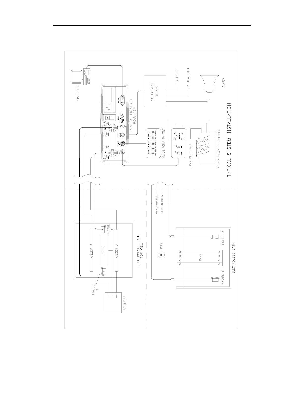
FIGURE 5 TYPICAL SYSTEM SETUP ................................................................................................10
FIGURE 6 PARAMETER MENU LAYOUT ..........................................................................................11
FIGURE 7 FRONT PANEL BUTTONS.................................................................................................19
FIGURE 8 GRAPH OF INTERVAL TIME AND DWELL TIME %............................................................29
FIGURE 9 DISCRETE INPUT CONNECTOR, 6 PIN MINI-DIN ..............................................................42
FIGURE 10 DISCRETE OUTPUT CONNECTOR, 8 PIN MINI-DIN ........................................................44
FIGURE 11 DAC I/O CONNECTOR, 7 PIN MINI-DIN .......................................................................46
FIGURE 12 TYPICAL RS-232 INTERFACE CABLE............................................................................47
List of Tables
TABLE 1 PROCESS 2 PARAMETER DEFAULT VALUES.....................................................................14
TABLE 2 SAMPLE PROCESS PARAMETER VALUES..........................................................................15
TABLE 3 DISCRETE INPUT CONNECTOR PIN ASSIGNMENTS ...........................................................42
TABLE 4 DISCRETE OUTPUT CONNECTOR PIN ASSIGNMENTS........................................................44
TABLE 5 DAC I/O CONNECTOR PIN ASSIGNMENTS.......................................................................46
TABLE 6 RS-232 CONNECTOR PIN ASSIGNMENTS .........................................................................47
TABLE 7 UPLOAD PARAMETER STORE...........................................................................................49
TABLE 8 SELECT PARAMETER CODES ............................................................................................51
TABLE 9 REMOTE ACTIVATION COMMAND CODES........................................................................54
TABLE 10 UPLOAD MACHINE STATUS CODES................................................................................55
TABLE 11 MONITOR STATUS REGISTER ......................................................................................... 55
TABLE 12 FAILURE REGISTER........................................................................................................56
TABLE 13 FLAG REGISTER.............................................................................................................56
TABLE 14 MODE REGISTER............................................................................................................56
TABLE 15 RS-232 ERROR REGISTER .............................................................................................57
TABLE 16 OUTPUT #1 STATUS REGISTER ......................................................................................57
TABLE 17 OUTPUT #2 STATUS REGISTER ......................................................................................57
TABLE 18 DATA LOGGING BIT MAP...............................................................................................60
TABLE 19 PROBE FLAG REGISTER .................................................................................................61
TABLE 20 SUMMARY OF CALIBRAT ION ADJUSTMENT....................................................................71
TABLE 21 MATERIAL CONSTANTS .................................................................................................72
ix
Page 8

Page 9

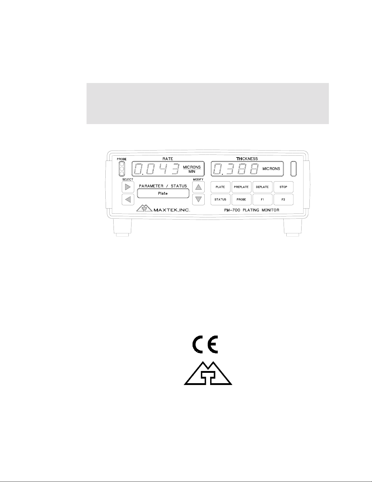
PM-700 SERIES PLATING MONITOR
1. GENERAL DESCRIPTION
The PM-700 Series of Plating Monitors act like intelligent electronic coupon
systems. The monitor continuously displays the thickness of the film on the
coupon and the rate of change of that thickness. It does this rapidly, in fractions
of a second, and with very high resolution.
The heart of the intelligent coupon is the quartz crystal mounted in the end of the
probe. It is the film on this crystal whose thickness and rate of change of
thickness is displayed on the monitor.
Use of this technique allows instantaneous measurement and display of the plating
rate of any liquid plating or etching process.
The basic monitoring system consists of the monitor itself, a probe with the
crystal installed and a cable connecting the probe to the monitor.
Various configurations of monitor, probe and crystal are available to meet
different requirements and the monitors incorporate numerous user modifiable
parameters so that they can be tailored to specific processes.
1
Page 10

PM-700 SERIES PLATING MONITOR
1.1 SPECIFICATIONS
PM-700 Series Common Specifications
Monitor accuracy: 0.5 %
Basic measurement resolution:
Thickness: 0.01 µg/cm2
Frequency: 0.5 Hz @ 5 MHz
Display Resolution:
Weight: 0.01 µg/cm2
Efficiency: 0.1%
Frequency: 0.1 Hz
Discrete Outputs:
Preplate achieved.
Thickness achieved.
Low rate alarm.
High rate alarm.
Crystal failed.
Spare.
Spare.
Level: 0 to 5 Vdc CMOS logic level.
Source impedance: 100 ohm.
Discrete Inputs:
Start Preplate.
Start Plate.
Start Deplate
Stop or Reset.
Spare.
Logic level: Ground true.
Internal 4.7 kς pull-up to 5 Volt.
DAC Interface:
Outputs: Two independent analog outputs
Range: 0 to 5.0 Vdc
Accuracy: ± 3% of range + 1% of full scale.
Linearity: 0.5% of full scale
Output impedance: 10 kς ± 2%
Control inputs: Zero, Full Scale
Logic level: Ground true.
Internal 4.7 kς pull-up to 5 volt.
2
Page 11

PM-700 SERIES PLATING MONITOR
Plate/Deplate Current Supply:
Range: 0 to ± 22.12 ma.
0 to ± 1.615 ASD (amp per sq. decimeter)*
0 to ± 15 ASF (amp per sq. foot)*
* For standard crystal electrode area of 1.37 cm2
Resolution: 0.05%
Linearity: 0.1%
Accuracy: ± (0.5% of value + 0.1% full scale)
Compliance: ± 4 Vdc
RS-232 Interface:
Connector: 9 Pin, Male, D shell (IBM AT type)
Baud Rate: 9600, Full Duplex
Format: 8 bits, No parity, 1 Stop bit
Environmental:
Operating Temperature: 0 to 50o C.
Storage Temperature: -40o to +70o C.
Humidity: Up to 95% relative humidity at or below +40o C;
to 75% relative humidity from +41o to +50o C.
Power requirement: 90 VRMS to 140 VRMS or
200 VRMS to 260 VRMS
at 47 to 63 Hz, 25W.
Physical
Dimensions:
Height: 89 mm (3.5 in.)
Width: 216 mm (8.5 in.)
Depth: 235 mm (9.25 in.)
Net Weight: 8.3 kg (3.75 lbs.)
Shipping Weight: 11.3 kg (5.1 lbs.)
3
Page 12

Page 13

PM-700 SERIES PLATING MONITOR
2. UNPACKING, INSPECTION AND BENCH CHECKOUT
2.1 UNPACKING, INSPECTION
Carefully inspect your plating monitor and its shipping container for evidence of
possible shipping damage. If such evidence is present, notify the carrier and
Maxtek as soon as possible. Keep the shipping container as evidence if shipping
damage is present or for possible future return of the monitor. Check the material
received against the packing list to ensure that all materials are accounted for.
Items included with your plating monitor are:
1 Plating Monitor
1 Operation and Service Manual
1 Power cord
In addition, you may have ordered one or more of the accessories. If there is no
evidence of damage, the monitor can now be bench checked.
2.2 BENCH CHECKOUT
Before connecting ac power to your Plating Monitor, make sure input voltage
requirement is correct for your installation. The selected line voltage can be seen
through the plastic window on the monitor rear panel. If it does not correspond to
the power line voltage to be used, follow the steps below to select the correct line
voltage.
1. Slide plastic cover to the left, exposing fuse and voltage selector p.c. board.
2. Remove fuse by pulling "FUSE PULL" lever to the left.
3. Remove voltage selector p.c. board by pulling it with a suitable tool on the
small hole in the center of the board.
4. Select the voltage by positioning the p.c. board so the desired voltage is
indicated on upper left corner. Insert board into place in this position.
5. Install fuse and slide cover to the right. The selected voltage will be visible
through the plastic window.
Connect the ac power cord to the monitor rear panel line connector. Turn on the
monitor via the rear panel rocker switch. When power is applied to the monitor it
goes through an internal test routine during which all displays and indicators are
lit up. This condition lasts approximately six seconds. The Rate and Thickness
displays will begin to flash a P FAIL message indicating that power has been
interrupted. This is normal and it will happen every time the monitor is turned
off.
5
Page 14
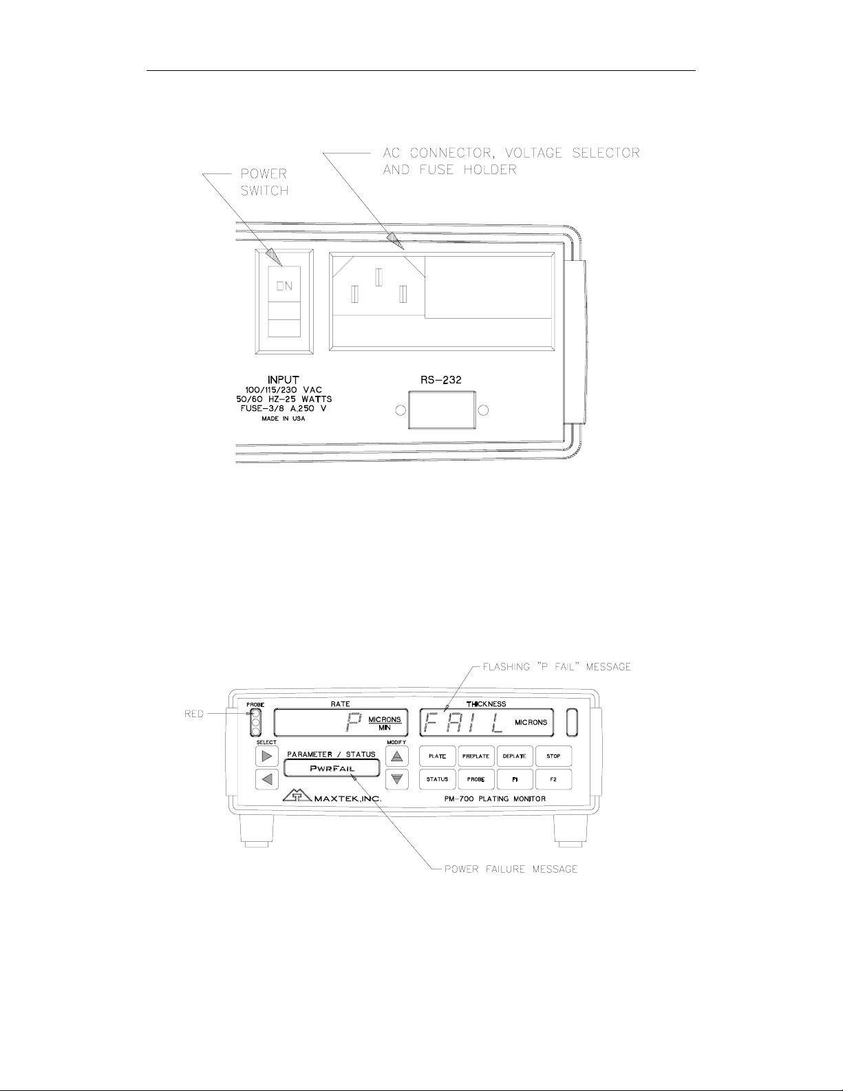
PM-700 SERIES PLATING MONITOR
Figure 1 Power Switch and AC Connector
You may see an E FAIL or I FAIL message for a short time, this is normal.
However, if the display stops on either of those messages, an internal fault has
been detected and the monitor will remain inoperative until the fault has been
corrected. Further details of error messages can be found in the Troubleshooting
Section on page 63.
Figure 2 Front Panel Indication, First Power-On
Press the Stop button to clear the P FAIL message. Now, an O FAIL will be
flashing. The red light in the Probe Status window will be on indicating a probe
failure, because there is no probe with crystal has been connected to the monitor.
Note that during actual operation, a P FAIL message indicates the line power to
6
Page 15

PM-700 SERIES PLATING MONITOR
the monitor has been interrupted. The red light in the Probe Status window and
the O FAIL message indicates a problem with the probe or the sensor crystal.
The Parameter/Status display will show the last display mode selected prior to
removing power from the monitor. See Parameter/Status Display Modes Section
on page 26 for detail description of the Parameter/Status display.
Using the standard 3 meter triaxial cable and connect the Sensor Probe to the
Plating Monitor rear panel connector labeled PROBE A. Be careful not to touch
the surface of the sensor crystal installed in the crystal holder. After the Sensor
Probe has been connected, pressing the STOP button should step Probe Status
Indicator from red to green indicating a good Sensor Probe is connected and is in
active. The O FAIL message then should be clear.
Pressing PLATE or PREPLATE will reset thickness display to zero. Breathe
lightly onto the sensor crystal surface. The displayed thickness should increase
due to condensed water vapor on the crystal. The thickness then will decrease as
additional water vapor evaporates from the crystal surface.
If your monitor is a dual probe model, you may also want to connect a second
Sensor Probe to the monitor connector labeled PROBE B. You will need to make
Probe B the active probe by pressing PROBE B button follow by PLATE button
(Note that Probe A is now in standby). An O FAIL message should flash in the
main display indicating Probe B has been failing. Press STOP key, the O FAIL
message should be clear and the Probe B Status Indicator should change from red
to green. Probe B is now the active probe. Test Probe B the same way you have
tested Probe A.
If everything responds as described above, the total system is OK. The monitor
can now be programmed to suit your application.
7
Page 16
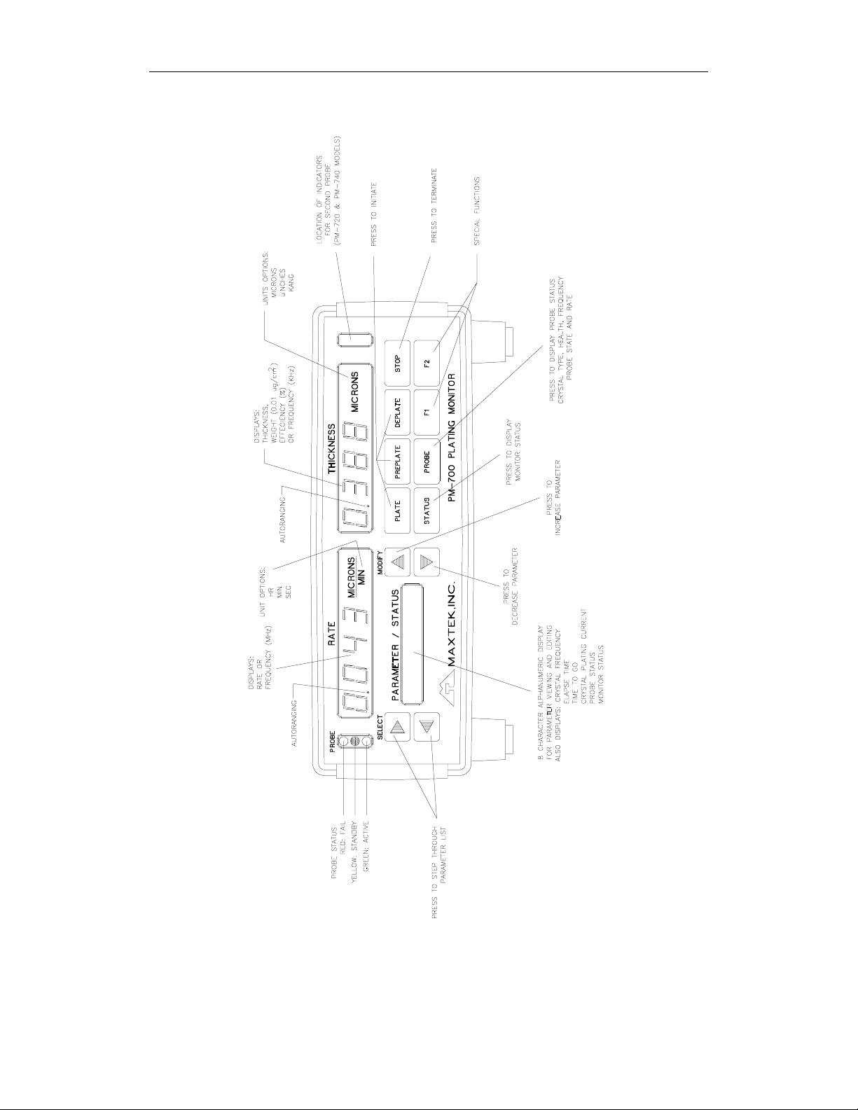
PM-700 SERIES PLATING MONITOR
Figure 3 PM-700 Front Panel Outline
8
Page 17
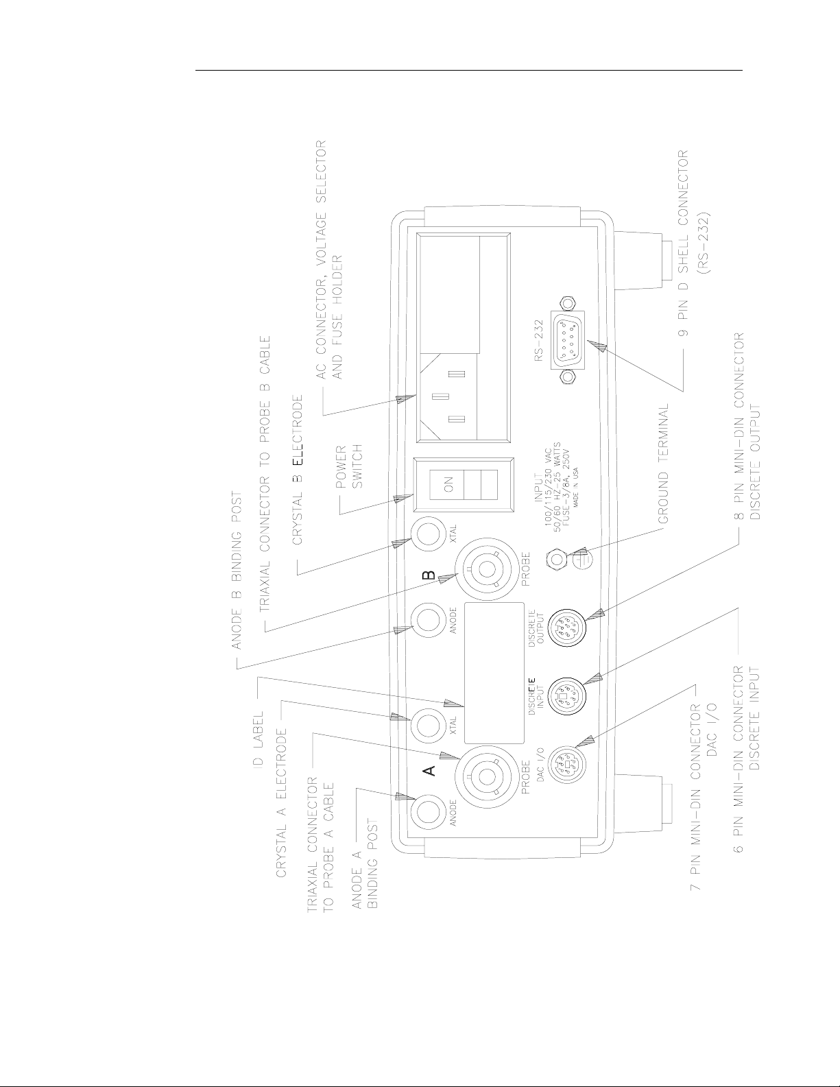
PM-700 SERIES PLATING MONITOR
Figure 4 PM-720 & PM-740 Rear Panel Outline
9
Page 18
PM-700 SERIES PLATING MONITOR
10
Figure 5 Typical System Setup
Page 19
PM-700 SERIES PLATING MONITOR
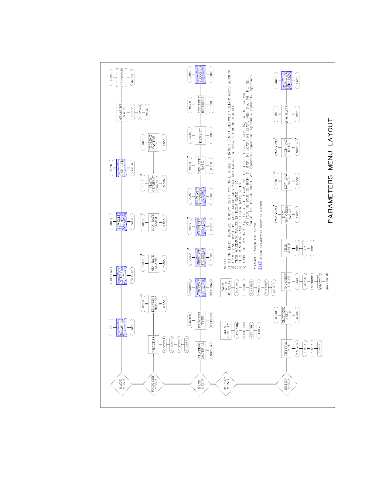
Figure 6 Parameter Menu Layout
11
Page 20

Page 21

PM-700 SERIES PLATING MONITOR
3. SIMPLIFIED OPERATION
This section is designed to help first time user of the PM-700 Series Plating
Monitor to become familiar with viewing, programming and editing of the
monitor parameters.
First, refer to Figure 7 Front Panel Buttons on page 19, locate the four arrow
buttons and study their functions. Next, refer to Figure 6, Parameter Menu
Layout, on page 6 and study the way the menus and parameters are laid out.
Notice that the SELECT buttons (left and right arrows) are used to move
horizontally through the parameters. The two MODIFY buttons (up and down
arrows) are used to vertically step through the menus or to change a parameter
value. Note that these arrow buttons have auto repeat functions. If one of them is
pressed and held down it will scroll to the ultimate limit (i.e. if you are at a
parameter with a numerical value, pressing and holding down the MODIFY UP
arrow will ultimately increase that parameter value to its maximum limit).
PM-700 Series Plating Monitor are shipped with Process Number 2 as the default
process. Process Number 1 may be programmed to your specific plating process
if you requested Maxtek to do so at the time you purchased your monitor. The
following table is a list of parameters default values for Process Number 2. Use
the four arrow buttons you have just learned above to step through the parameters
and check their default values against the list. Also, practice changing some of
the parameter values to get a feel on how to modify them. There are four material
parameters that could be reset to their factory set default values. If you wish to do
so, simply press the STATUS button while both of the Up and Down arrow
buttons are depressed.
13
Page 22

PM-700 SERIES PLATING MONITOR
Table 1 Process 2 Parameter Default Values
Menu Parameter Default Value
Mode Menu Sample Off
Mode Menu Measure Mode * Single
Mode Menu ProbSwap * Manual
Process Menu Process Number 2
Process Menu Endpoint Setting 10.00
Process Menu Min Rate Alarm 0.000
Process Menu Max Rate Alarm 9.999
Process Menu Plate Current Density 0.001
Bath Menu Bath Special1
Bath Menu Type Elecless
Bath Menu Preplate Thckness 1.000
Bath Menu Preplate Rate 0.200
Bath Menu Deplate Rate 0.100
Bath Menu Density 1. 000
Bath Menu Acoustic Ratio 8.830
Display Menu Main Display Rate Thk
Display Menu Parm Status Display Status
Setup Menu Crystal Type 5 MHz
Setup Menu Crystal Area cm^2 1.370
Setup Menu DAC Thckness Range 5.000
Setup Menu DAC Low Rate 0.000
Setup Menu DAC High Rate 9.999
Setup Menu Simulate Mode Off
* These parameters are only available in dual probe models.
14
The following example is a typical plating process. It is provide for you to
practice parameter programming.
Page 23
PM-700 SERIES PLATING MONITOR
3.1 SAMPLE PROCESS
Suppose a PM-700 monitor is to be used to continuously measure the plating rate
and thickness in an electroless nickel bath, giving a deposit with 6%
phosphorus. Since this bath will not initiate plating on a pure gold surface, the
sensor crystal will have to be electrolytically preplated with, for example, .5
microns of nickel at a controlled rate in order to support subsequent autocatalytic
electroless plating. Assume that the desired plating thickness endpoint is 20
microns and it is desired that the plating monitor warns the operator if the plating
rate falls outside the normal limits of .100 ±0.02 micron/min. It is also desired
that the total elapsed time since introduction of the work into the plating bath be
displayed. These parameters will be established for process number 3.
Given the above example, the following list of parameters will need to be
programmed into the monitor.
Table 2 Sample Process Parameter Values
Menu Parameter Value
Process Menu Process Number 3
Process Menu Endpoint Setting 20.00
Process Menu Min Rate Alarm 0.080
Process Menu Max Rate Alarm 0.120
Mode Menu Sample Off
Bath Menu Bath Ni 6%P
Bath Menu Type Elecless
Bath Menu Preplate Thckness 0.500
Bath Menu Preplate Rate 0.050
Display Menu Parm Status Display Elaptime
Setup Menu Simulate Off
Since the above parameters will be established for process number 3, the first
thing to do is select process number 3 as the current process. You can do this by
going to the Process parameter in the Process Menu and use the SELECT arrow
buttons to find Number 3. Then follow the above list to program the rest of the
parameters.
15
Page 24

Page 25

PM-700 SERIES PLATING MONITOR
17
Page 26

PM-700 SERIES PLATING MONITOR
4. DETAILED OPERATION
4.1 INTRODUCTION AND GENERAL CONCEPTS
Basic operation of the PM-700 monitors is straightforward but the many options
and operating modes available through the programmable parameters may appear
overwhelming on first glance. We believe, however, that once the basic operating
concepts are understood, operation of the system will be experienced as
straightforward and intuitive.
In order to facilitate a rapid understanding of the PM-700's basic operating
concepts, we have seen fit to describe the operation in terms of modes and states.
The monitor has a number of operating states and modes, which are described
below. In addition, the probes themselves have their own states and modes, which
may be different than those of the monitor.
For example, the monitor may be operating in the electroless plating mode; the
measurement mode might be single probe, with sampling. The monitor might
then be in the Plate State (as opposed to the Ready, Preplate, or EndPoint states).
Meanwhile the probe might also be in the Plate State or alternately in the Hold
State if the monitor is between samples. If the monitor supports dual probes, then
the second probe will likely be in the hold mode or it could be in the failed state if
the crystal is being replaced.
The monitor is shipped from the factory with default settings for all parameters so
that no more than a few parameters must be setup to begin operation.
4.2 DISPLAYS
There are five display windows in the plating monitor front panel. On the upper
left most and upper right most are the Probe Status windows. Each contains three
indicator LED's. Note that in the PM-700, only the left status window is utilized
since PM- 700 supports single probe. Located in- between the two Probe Status
windows is the Rate and Thickness displays. Each contains four large numerical
LED's for easy readout of monitor measurements. Below the Rate display is the
Parameter/Status display. This is an 8 character alphanumeric display used for
parameter programming, viewing and editing. It is also used for displaying the
monitor status or other functions. See Figure 3, page 6.
4.3 BUTTONS
There are twelve membrane push buttons on the plating monitor front panel. The
four left most buttons are used for parameter viewing and editing, and the eight
right most buttons are monitor operational buttons. Their uses are described
below.
18
Page 27

PM-700 SERIES PLATING MONITOR
Figure 7 Front Panel Buttons
19
Page 28

PM-700 SERIES PLATING MONITOR
Select Buttons
Select Buttons are used to step between parameter items.
Modify Buttons
Modify Buttons are used to step up and down between menus, and to modify
parameters values.
Plate Button
Plate Button is used to initiate the plating process.
Preplate Button
Preplate Button is used to initiate the preplate process.
Deplate Button
Deplate Button is used to initiate the deplate process.
Stop Button
Stop Button is used to terminate any active process. It is also used to clear failure
messages.
Status Button
When Status Button is pressed down, the Parameter/Status Display will
sequentially display important information involving the currently selected
process, such as thickness endpoint, type of bath, etc. This will save the user of
having to go to each menu to verify these parameters.
Probe Button
This button, when pressed, will display the Probe Sensor status in the Rate and
Thickness windows. The two left most digits of the Rate display shows the
crystal type. The next two digits show the crystal health and the Thickness
display will show the crystal frequency in megahertz. In PM-720 and PM-740
models, this button is labeled Probe A.
Probe B Button
This button is used in the same way as Probe A button. Probe B status
information will be displayed.
In PM-700 model, this button is labeled F1 and there is no function assigned to it.
Spare buttons
The lower right most button, either labeled F2 (PM-700) or F1 (PM-720 & PM-
740), is spare. Its function is not implemented.
20
4.4 OPERATION
The operation of the PM-700 is described in terms of Monitor States and
Measurement Modes and Probe Activity States and Operating States.
Page 29

PM-700 SERIES PLATING MONITOR
4.4.1 Monitor Operating States
The PM-700 can be in any one of a number of Operating States depending upon
the type of bath being monitored, electrolytic or electroless.
4.4.1.1 Electroless plating
Five different states are defined for operation with electroless plating baths.
4.4.1.1.1 Ready State
In the Ready State plating rate and thickness are being monitored, but the
Endpoint check is not being performed and the crystal electrode current is zero.
The Ready State is entered on power ON and also by pressing the Stop button.
Pressing the Preplate, Plate or Deplate buttons steps the monitor from the Ready
State into the selected state.
4.4.1.1.2 Preplate State
The Preplate State is activated by pressing the Preplate button while in the Ready
mode. If pressed in any state other than the Ready State, the Preplate button has
no effect. Upon entry to the Preplate state the crystal electrode current is adjusted
by the monitor to achieve the Preplate Rate parameter value and is maintained
until the Preplate Thickness is achieved at which time the monitor steps to the
Plate state.
4.4.1.1.3 Plate State
The Plate State can be entered from the Ready State, Preplate State or Deplate
State by pressing the Plate button or automatically upon completion of the
Preplate State. During the Plate State the indicated thickness is compared with
the Endpoint parameter. When the indicated thickness equals or exceeds the
Endpoint parameter, the monitor steps to the Endpoint State.
4.4.1.1.4 Deplate State
The Deplate State can be entered from the Ready State or the Endpoint State by
pressing the Deplate button. (Remember that monitor states are not the same as
probe states.) The Deplate State is exited to the Ready State by pressing the Stop
button or to the Plate State by pressing the Plate button. The Deplate State is
automatically terminated when the crystal health recovers to 95% at which time
the monitor returns to the Ready State.
4.4.1.1.5 Endpoint State
The Endpoint State is automatically entered from the Plate State when the
indicated thickness equals or exceeds the Endpoint parameter value. Pressing the
Stop or Deplate buttons steps the monitor from the Endpoint State to the Ready or
Deplate state. The Preplate and Plate buttons produce no action while in the
Endpoint State.
21
Page 30

PM-700 SERIES PLATING MONITOR
4.4.1.2 Electrolytic plating
Because the Preplate State is not necessary in the Electrolytic plating mode, the
Preplate button is ignored and only four different monitor states are defined for
this operating mode.
4.4.1.2.1 Ready State
In the Ready state plating rate and thickness are being monitored but the crystal
electrode current is zero so no plating will be occurring. The Ready State is
entered on power ON and also by pressing the Stop button. Pressing the Plate or
Deplate buttons steps the monitor from the Ready State into the selected state.
4.4.1.2.2 Plate State
The Plate State is entered from the Ready State by pressing the Plate button.
During the Plate state the crystal electrode current is set at the value required to
achieve a plating current density equal to that programmed in the Current Density
parameter. In addition, the indicated thickness is compared with the Endpoint
parameter. When the indicated thickness equals or exceeds the Endpoint
parameter, the monitor steps to the Endpoint State.
4.4.1.2.3 Deplate State
The Deplate State is entered from the Ready State or the Endpoint State by
pressing the Deplate button. In this state the crystal electrode current is adjusted
by the monitor as required to achieve the de-plating rate specified by the Deplate
Rate parameter. The Deplate State can be exited to the Ready State by pressing
the Stop button, or to the Plate State by pressing the Plate button. The Deplate
State is automatically terminated to the Ready State if the crystal health increases
to 95% or more.
4.4.1.2.4 Endpoint State
The Endpoint State is automatically entered from the Plate State when the
indicated thickness equals or exceeds the Endpoint parameter value. Pressing the
Stop or Deplate buttons steps the monitor from the Endpoint State to the Ready or
Deplate state. The Plate button is ignored while in the Endpoint State.
4.4.2 Monitor Measurement Modes
4.4.2.1 Single Probe Measurement Modes
The following three measurement modes require only one probe and can be
utilized on any of the PM-700 series of monitors.
22
4.4.2.1.1 Continuous
In this mode the bath is monitored continuously. Should the Probe fail during the
Preplate, Plate or Deplate state, the failure is enunciated, the Rate Display is held
at its most recent value, and the displayed Thickness is increased at the displayed
rate to indicate the best guess for the substrate thickness buildup.
Page 31

PM-700 SERIES PLATING MONITOR
4.4.2.1.2 Sample
This mode is used to increase the crystal's range. In the Sample mode the plating
rate is monitored on a sampled basis. Between samples the rate established during
the last sample is displayed and the displayed thickness value is increased at the
displayed rate to show the assumed substrate thickness buildup. Plating of the
probe crystal is halted by applying enough deplating current to the crystal to hold
the plating rate at zero. Should the Probe fail, the failure will be enunciated, but
the displayed thickness will continue to increase on the basis of the last valid rate
sample. Parameters are provided to allow the user to set the duration of the
sample period and the interval between sample periods.
4.4.2.1.3 Sample with Deplate
This mode is identical to the Sample mode except that the Probe crystal will be
electrolytically deplated between samples. The amount of deplating is established
by the user as a percentage of the amount plated during the sample. The rate of
deplating is set by the amount, which must be deplated, and the time between
samples.
4.4.2.2 Dual Probe Measurement Modes
The following measurement modes require two probes and, therefore, require the
use of a Dual Probe model.
4.4.2.2.1 Auto Probe Swap
The Auto Probe Swap mode can be applied to all three of the Single Probe
measurement modes. In the Auto Probe Swap mode a second probe is installed in
the bath. While the active probe monitors the bath, the second probe is held in
standby. In the event of a failure of the active probe, the monitor will automatically switch to the second, or standby, probe. If the standby probe requires
initializing, it will be initialized with a preplate cycle, prior to the swap. During
the time it takes the unit to switch over to the second probe, the rate display is
held at the last valid rate value and the displayed thickness continues to buildup at
the displayed rate.
4.4.2.2.2 Alternating Measurement mode
In this mode two probes are used to provide continuous monitoring. Usage of the
two probes is alternated. While one probe is monitoring the bath the second probe
is being deplated. The percentage of deplate between plating cycles is established
by the user. The rate at which the two probes are alternated is determined by the
Sample Interval parameter. The alternate probe is changed back to the plate mode
10 seconds before the probes are switched. This is done so when the probes are
switched, the plating rate is stabilized on the new probe. In the event that one of
the probes fails, the monitor reverts to the single probe Sample with Deplate
mode.
4.4.2.2.3 Dual Probe Measurement mode
23
Page 32

PM-700 SERIES PLATING MONITOR
In this mode both probes are actively monitoring the plating process. The monitor
compares the two probes and computes the average and the percentage difference
between the probes. A number of display modes are available.
4.4.3 Probe States and Modes
At any particular time a Probe can be in any one of three states and,
independently, in any one of three modes. For instance a Probe could be in the
Standby State and the Deplate mode or in the Standby State and the Hold mode.
The possible states and modes are described below:
4.4.3.1 Probe States
A probe can be in any one of the following three states: Failed, Standby, or
Active. The state of the probe is indicated by the three probe status LED's. (See
Figure 3.)
4.4.3.1.1 Failed state.
A failed probe means that for some reason, the monitor is not receiving a valid
frequency signal from the probe.
4.4.3.1.2 Standby state
The standby state indicates that the monitor is receiving a valid frequency from
the probe but the displayed information is not based on the output of this probe.
4.4.3.1.3 Active state
The active state indicates that the probe is not failed and that it is the source of the
display information and is being used to control any active process.
4.4.3.2 Probe modes
In addition to the above, a probe may be in any one of the following four modes:
Hold, Deplate, Preplate, or Plate. The Hold and Preplate modes are applicable to
the electroless plating process. The Probe Deplate and Probe Plate mode is
applicable to both the electroless and the electrolytic plating processes.
4.4.3.2.1 Ready mode
In the Ready mode, the probe is not in preplate, deplate, plate or hold. The
monitor does not supply current to the probe.
4.4.3.2.2 Hold mode
In the Probe Hold mode, the plating rate on the probe is held at zero. For
electroplating processes, this is done by setting the electrode current to zero. For
electroless processes, this is done by maintaining the electrode current at the
negative value required to halt the electroless plating process. This current level
is automatically determined by the monitor.
24
Page 33

PM-700 SERIES PLATING MONITOR
4.4.3.2.3 Deplate mode
In the Probe Deplate mode, enough negative electrode current is supplied by the
monitor to create the desired deplating rate.
4.4.3.2.4 Preplate mode
In the Probe Preplate mode, enough positive electrode current is supplied by the
monitor to create the desired preplating rate.
4.4.3.2.5 Plate mode
In the Probe Plate mode, the electrode current is zero for electroless processes and
positive for electrolytic processes. In electrolytic processes the electrode current
is established by the monitor at the value necessary to achieve the programmed
current density.
The mode of the probe can be determined by pressing the Probe status button.
4.4.4 Main Display modes
The two four digit main displays are factory set to display plating rate and plating
thickness, however, three alternate display formats can be selected by means of
the Main Display parameter. All four possible Main Display modes are described
below.
4.4.4.1 Rate and Thickness
This is the normal or default display mode as set at the factory. The measurement
units will normally be displayed to the right of the digits unless the display units
have been changed from those that were preset at the factory. If the Thickness
Units parameter has been used to select and alternate set of units, then both units
display areas will be dark. If the Time Units parameter has been modified, but the
Thickness units are unchanged, then only the Rate display units will be dark.
4.4.4.2 Rate and Efficiency
In the Rate and Efficiency main display mode, the normal rate display is provided
in the left hand display area while the right hand display is used to display the
cathode efficiency in percent where 100% represents the theoretical maximum for
the bath selected. Since cathode efficiency is only meaningful for electrolytic
processes, a value of 00.00 is displayed if the monitor is in the Electroless plating
mode.
4.4.4.3 Efficiency and Thickness
In this display mode, the left-hand display area is used to display the cathode
efficiency in percent where 100% represents the theoretical maximum of the bath
selected. Since cathode efficiency is only meaningful for electrolytic plating
processes, a value of 00.0 is displayed if the monitor is in the Electroless plating
mode. The right hand display area provides the normal plating thickness display.
25
Page 34

PM-700 SERIES PLATING MONITOR
4.4.4.4 Frequency
In this Main Display mode the left-hand display is used to display the crystal
frequency in Megahertz while the right hand display is used to display the crystal
frequency in Hertz. This allows for display of the total crystal frequency to a
resolution of 0.1 hertz.
4.4.5 Parameter/Status Display modes
The Parameter/Status display serves a number of purposes. It is used to view and
modify parameter values, or to display monitor status or to display a user selected
variable. In the event of a warning condition or a failure condition, a descriptive
message will be flash alternately with the selected display.
When any of the arrow buttons are pressed, the display is used to show the value
of the previously selected parameter. Pressing one of the Probe buttons results in
the display of that probe's status alternating with the plating rate on that probe. If
the Status button is pressed, then the display cycles through a list of items, which
describe the status of the monitor. When the Probe or Status buttons are released,
or if the arrow buttons remain inactive for 30 seconds, then the display reverts to
one of the six displays described below. The 30-second hold of the parameter
display can be terminated early by pressing and releasing any of the Probe or
Status buttons.
4.4.5.1 Status Display
In the Status Display mode, the monitor state is displayed.
4.4.5.2 Frequency Display
In the Frequency Display mode the frequency is displayed as an eight-digit
number with a resolution of 0.1 hertz.
4.4.5.3 Elapsed Time Display
This display mode displays the time that has elapsed since the beginning of the
current state. I.e., if the current state is the Plate State then the time displayed is
the amount of time that has passed since the start of the Plate State. The time is
displayed in hh:mm:ss format.
4.4.5.4 Time to Go Display
This display mode displays the estimated time required to complete the current
state. In the case of the Plate State, the time to go is calculated by dividing the
difference between the Endpoint thickness and the current thickness by the
average rate.
4.4.5.5 Current Density Display
This display mode displays the current density at the probe electrode. The units
are Ampere per square decimeter for monitors with metric unit display and
Amperes per square foot for monitors with English unit display.
26
Page 35

PM-700 SERIES PLATING MONITOR
4.4.5.6 A-B)% Display
This display mode is only available on dual probe model monitors. In the Dual
Probe measurement mode, this display shows the percentage difference between
A and B probe measurements. The right four characters of the Parameter/Status
display indicate the percentage difference between the measurements made by the
A and B probes, the average of which is displayed in the right hand Main display.
The quantity displayed is 100*(A- B)/(A+B) or the percentage that the
measurement A is larger than the average of the two measurements. The format
of the display is +XX.X or -XX.X. A positive sign indicates that the A
measurement is larger than the B measurement. The left four characters of the
Parameter/Status display indicate the percentage difference between the
measurements made by the A and B probes, the average of which is displayed in
the left hand Main display. The same format is used.
4.4.6 Simulation Mode
The PM-700 series of monitors include a simulation function that is useful for
familiarization and demonstration of the monitor features and for trouble
shooting. In the simulation mode the frequency signal from the Probe is replaced
with a simulated frequency that reflects the change in frequency, which an ideal
crystal would produce when plated at the rate, specified by the Simulate Rate
parameter. The Simulation State is activated by the Simulation Mode parameter.
4.5 PARAMETERS
The PM-700 series of monitors incorporate a large number of parameters that
allow fine-tuning of the monitor for a particular application. All parameters are
provided with default factory set values so that the user need only be concerned
with those parameters that he desires to change. There are two different types of
parameters; they are the selection type and the value type. Selection type
parameters are parameters that are limited to a small number of possible
selections. Some have only two selections, On and Off. Value type parameters
may have any numeric value between a maximum and a maximum value.
4.5.1 Viewing and modifying
Pressing any one of the arrow keys results in the display of the last viewed
parameter. The parameters are arranged in five different menus according to their
usage. See Figure 6. Once a parameter is displayed, the left and right arrow keys
provide for horizontal movement as shown in Figure 7. The up and down keys
allow for vertical movement which corresponds to selection of selection type
parameters or for increasing or decreasing the value of value type parameters.
Note that movement between menus is only available when menus are being
displayed as indicated by the vertical lines between the menu selections. Holding
the left arrow key down will rapidly take you to the menu parameter. The up and
down keys can then be used to choose a particular menu. The rate at which value
type parameters change value increases for as long as a direction key is held
down. When the key is released, the rate of change returns to its minimum value.
27
Page 36

PM-700 SERIES PLATING MONITOR
This feature allows for very fine setting over a very broad range in a minimum
amount of time.
4.5.2 Hidden parameters
Parameters, which are not applicable to the selected mode of operation, are not
displayed. They are hidden. For example, Interval Time and Dwell Time are
applicable only when the monitor is in the Sample measurement mode. Thus
when the Sample mode is Off, these parameters are hidden. See Section 4.5
starting on page 27 to determine which parameters may be hidden and under what
conditions.
4.5.3 Descriptions
The following is a list of the available parameters, organized according to menu,
along with their type and their range.
28
Page 37

PM-700 SERIES PLATING MONITOR
Figure 8 Graph of Interval Time and Dwell Time %
29
Page 38

PM-700 SERIES PLATING MONITOR
4.5.3.1 Mode Menu
Numonic Name/Description Minimum Maximum Default
Sample Sample
Allows the user to turn the
monitor Sample Mode on or
off. For a detail description of
Sample Mode operation, refer
to Sample section. Note this
parameter will be hidden if the
Measure Mode parameter is
set to Altrntng.
Interval
Time
Interval Time
Defines the time of one
sampling cycle. Refer to
Figure 11 for an illustration of
Interval Time. Note that this
parameter will be hidden if the
Sample Mode is off.
Dwell
Time
%
Dwell Time Percentage
Defines the time, as a
percentage of the Interval
Time, during which the
monitor is actually taking
measurement from the Sensor
Probe. Figure 11 illustrates
Dwell Time % with respect to
Interval Time. Note this
parameter will be hidden from
the Mode Menu if the Sample
parameter is set to Off. I t a lso
is hidden if the Measure Mode
is set to Altrntng.
Off On Off
00:00:00
HH:MM:SS
99:59:59
HH:MM:SS
00:01:00
000.0 099.9 050.0
30
Deplate Deplate
Sets the plating monitor to
Automatic Deplate Mode or
Manual Deplate Mode. This
parameter will be hidden if the
Sample Mode is set to Off. It
is also hidden if the Measure
Mode parameter is set to
Altrntng.
Measure
Measure Mode Single Single
Manual Auto Manual
Page 39

PM-700 SERIES PLATING MONITOR
Mode Allows for selection of one of
the three measuring modes
listed in the Minimum
column. For detail description
of these modes, refer to
Monitor Measurement Modes
section. Note that this
parameter is only av aila ble in
the dual probe models.
ProbSwap Probe Swap
Sets the monitor to perform
probes swapping
automatically or manua lly.
Swapping Probes section
offers a detail description of
the Probe Swap feature. This
parameter is available only in
the dual probe models. Note
this parameter will be hidden
if the Measure Mode
parameter is set to Altrntng or
Dual.
Altrntng
Dual
Manual Auto Manual
31
Page 40

PM-700 SERIES PLATING MONITOR
p
4.5.3.2 Process Menu
Numonic Name/Description Minimum Maximum Default
Process Process
The plating monitor is
capable of holding up to
four different processes.
This parameter allows
selection of one of the four
processes.
EndPoint
Setting
Endpoint Setting
Allows setting of the plating
endpoint thickness. This is
the desired thickness to be
plated on the substrate.
When the monitor displaye d
thickness reaches this
thickness setting, the
monitor displayed thickness
will begin flashing rapidly,
informing the user that the
plating process is done.
Also, the Thickness
Achieved Output will goes
high (true). This output
could be used to turn on
other remote of alarming
device.
Number 1 Number 4 Number 1
0.000 999.9 10.00
32
Min Rate
Alarm
Max Rate
Alarm
Minimum Rate Alarm
Allows the user to set the
minimum allowable plating
rate. When the plating rate
drops below this set value,
the displayed rate will fla sh
rapidly. Also there is a Low
Rate Alarm Output that will
come on at this time. It
could be used to turn on
other remote alarming
device.
Maximum Rate Alarm
Similar to the Minimum
Rate Alarm
arameter, this
0.000 999.9 0.000
0.000 999.9 9.999
Page 41

PM-700 SERIES PLATING MONITOR
parameter allows the user to
set the maximum allowable
plating rate. The displayed
rate will flash rapidly , a nd
the High Rate Alarm Output
will come on.
Plate
Current
Density
Tooling
Factor
%
Plate Current Density
Establishes the current
density for the Sensor
Crystal electrode.
Tooling Factor Percentage
Use to calibrate for the
different in thicknesses, if
any, between the Sensor
Crystal and the pla ting
substrate.
0.000 1.615 0.001
1.000 999.9 100.0
33
Page 42

PM-700 SERIES PLATING MONITOR
4.5.3.3 Bath Menu
Numonic Name/Description Minimum Maximum Default
Bath Bath
This parameter contains a list
of readily programmed baths.
The user can simply select a
bath material that the plating
monitor will be used with.
See Figure___ for a list of
selectable bath.
Type Type
Defines the type of plating
bath that the monitor will be
used in, either electrode
plating or electroless plating .
PrePlate
Thckness
PrePlate Thickness
Defines the thickness to be
PrePlated on the cry sta l, as a n
adhesion layer, in electroless
plating bath. Note if the
monitor is set to work in
electrode plating bath, this
parameter will be turned off.
Special1
Elecless Electro Elecless
0.000 999.9 1.000
34
PrePlate
Rate
DePlate
Thckness
%
DePlate
Rate
PrePlate Rate
Defines the rate at which the
monitor will use in the Sensor
Crystal PrePlate proc ess. This
parameter will be off if Type
parameter is set for Electro.
DePlate Thickness Percentage
Defines a percentage of
thickness to be deplated off
the Sensor Crysta l.
DePlate Rate
Allows setting of the DePlate
rate at which the monitor will
use in DePlating the plated
material off the Sensor
Crystal.
0.000 999.9 0.200
0.000 999.9 50.00
0.000 999.9 0.100
Page 43

PM-700 SERIES PLATING MONITOR
Density Material Density
Allows setting of the density
of the material being plated so
that the monitor can calculate
and display the correct
physical film thickness. A list
of the commonly used
material density is pr ese nted
in Table 21.
Acoustic
Ratio
Acoustic Ratio
Allows setting of the acoustic
impedance of the plated
material. This value is
necessary for the monitor to
accurately establish the sensor
scale factor when the sensor
crystal is heavily plated. A
list of the commonly used
material acoustic impedance is
presen t e d i n Table 21.
0.800 99.90 1.000
1.500 999.9 8.830
ElecChem ElectroChemical Equivalent
Allows setting of the electro
chemical equivalent of the
plated material. A list of the
commonly used electro
chemical equivalent value is
presented in Table 21. Note
this value is only needed for
the electrolytic plating bath.
Therefore, this parameter is
hidden if the Type parameter
is set to Elecless (electroless).
0.000 9.999 1.000
35
Page 44

PM-700 SERIES PLATING MONITOR
4.5.3.4 Display Menu
Numonic Name/Description Minimum Maximum Default
Main
Display
Parm
Status
Display
Main Display Mode
This parameter allows a
selection of four different
Main Display Modes listed
in the Minimum column.
For a description of each of
these modes, refer to Main
Display Modes section.
Parameter/Status Display
Allows selection of one of
the six Display Modes
available to be display in the
Parameter/Status Display
window. These six Display
Modes are listed in the
Minimum and Maximum
columns. For further detail
of these modes, refer to
Parameter/Status Display
Modes section.
Rate Thk
Rate Eff
Eff Thk
Freq
Status
Freq
ElapTime
Rate Thk
TimeToGo
Status
Current
(a - b)%
36
Page 45

PM-700 SERIES PLATING MONITOR
4.5.3.5 Setup Menu
Numonic Name/Description Minimum Maximum Default
Crystal
Type
Electro
Area
Thckness
Units
Crystal Type
Allows the user to set the
monitor to work with different
types of cry stal frequency.
Selectable crystal frequency
are listed in the Minimum
column.
Crystal Electrode Area
Allows for Sensor Crysta ls
that have different electrode
area. Enter the electrode area
in cm2 if the crysta l in use is
not the monitor default area.
Thickness Units
Allows the user to change the
monitor default thickness
measurement unit to a
different measurement unit.
Warning if selected thickne ss
measurement is not the default
unit, the Thickness Unit
Display will be off.
2.5 MHz
5 MHz
3 MHz
5 MHz
6 MHz
9.999 0.100 1.370
kΧ
Micron
µInch
Micron
µg/cm2
mg/cm2
Time
Units
Selectable units are listed in
the Minimum column. For
other possible plating
measurement units, contact
manufacturer.
Time Units
Similar to the Thickness Units
parameter, this parameter
allows the user the change the
manufacturer default setting .
The Rate Units Display will
be off when the default is
changed. Minimum column
listed three selectable Rate
Measurement Units. Call
Maxtek for other possible rate
measurement units.
Hrs
Min
Sec
Min
37
Page 46

PM-700 SERIES PLATING MONITOR
DAC
Thckness
Range
Low DAC
Rate
High DAC
Rate
Digital to Analog Converter
Thickness Range
Establishes the full scale value
of the DAC. See Digital to
Analog Converters section for
a detail description.
Low DAC Rate
Establishes the lower limit of
the DAC rate scale factor.
See Digital to Analog
Converters section for further
details.
High DAC Rate
Establishes the higher limit of
the DAC rate scale factor.
See Digital to Analog
Converters section for further
details.
0.000 Maximum 5.000
0.000 High
0.000
rate
minus 10
Low rate
Maximum 9.999
plus 10
Simulate Simulate Mode
Allows user to turn the
monitor Simulate Mode on or
off. For detail description of
the Simulate Mode operation,
refer to Simulation Mode
section.
Simulate
Rate
Simulate Rate
Defines the rate at which the
monitor will use in Simulate
Mode. Refer to Simulation
Mode section for a detail
description. Note this
parameter is hidden if
Simulate parameter is set to
Off.
On Off Off
0.000 999.9 0.200
38
Page 47

PM-700 SERIES PLATING MONITOR
4.5.4 Restoring to Default Values
The four material parameters, Tooling Factor, Density, Acoustic Impedance and
ElecChem can be reset to their factory set default values by pressing the Status
button while both the Up and Down arrow buttons are depressed.
4.6 STATUS ASSESSMENT
4.6.1 Monitor Status
The monitor status can be assessed any time by pressing the Status button. When
the Status button is pressed, the following list of status parameters are displayed in
the Parameter/Status display:
Simulate mode
Monitor state
Process Number
Top Left display quantity
Top Right display quantity
PRM/STATUS display quantity
Sample mode (ON/OFF)
Deplate mode (Manual/Auto)
Probe Swap mode (Manual/Auto)
Bath Type (Electro/Elecless)
Material (Bath Material)
Time units (Hours/Minutes/Seconds)
Thickness units (KΧ/µinch/Micron/µg per cm2/mg per cm2)
Crystal type (6 Mhz/5 Mhz/3 Mhz/2.5 MHz)
4.6.2 Probe Status
Pressing the Probe status button results in the display of the following
information: crystal frequency type and health, crystal frequency in Megahertz, the
plating mode of the crystal, and the plating rate on the crystal.
The crystal frequency and type is displayed in the Rate display area.
The crystal frequency, in Megahertz, is displayed in the Thickness display area.
The Probe mode and the plating rate are displayed alternately in the
Parameter/Status display area.
39
Page 48

PM-700 SERIES PLATING MONITOR
4.7 SWAPPING PROBES
Swapping from the current active probe to the Standby probe can be manually
initiated at any time. If the Probe Swap parameter is set to Auto then automatic
probe swapping can occur.
4.7.1 Manual probe swapping
Manual probe swapping is accomplished by means of the Probe A and Probe B
buttons.
4.7.1.1 Assessing the probe status prior to initiating the swap.
Pressing the Probe button for the probe that you wish to switch over activates the
probe status display. The probe status display provides you with the information
you need to be sure that the alternate probe is working properly before you
command the swap.
4.7.1.2 Preplating prior to swapping.
Preplating of the standby probe can be initiated at any time prior to swapping
probes by pressing the Standby Probe's button and then pressing Preplate button
while holding the Standby Probes button down. This will initiate the Preplate
cycle on the Standby probe. How do we terminate? Care must be taken to insure
that the Standby Probe's button is pressed and held prior to pressing the Preplate
button or a Preplate cycle may be initiated on the Active probe.
4.7.1.3 Commanding the swap.
To command the swap, simply press the Plate button while continuing to hold the
Probe button down. The monitor will switch over to the alternate probe and the
Probe status display will indicate that the probes have been swapped. The
thickness accumulated on the previously active probe prior to the swap will be
added to that accumulated on the new probe after the swap so that the displayed
thickness will continue to increase at the displayed rate.
4.7.1.4 Deplating the Standby Probe.
Deplating of the Standby probe can be initiated at any time by pressing the
Standby Probe's button and then pressing the Deplate button while holding the
Standby probe's button down. This will initiate the Deplate cycle on the Standby
probe. Care must be taken to insure that the Standby probe's button is pressed and
held, prior to pressing the Preplate button. Otherwise, Deplate cycle may be
initiated on the Active probe.
4.7.1.5 Manual termination of Preplate or Deplate on the Standby probe.
Manual termination of a Preplate or Deplate cycle on the Standby probe can be
accomplished by pressing the Standby probe's button and then pressing the Stop
button while continuing to hold the Standby probe's button down. Again, care
must be taken to insure that the Standby probe's button is pressed and held prior to
40
Page 49

PM-700 SERIES PLATING MONITOR
pressing the Stop button or the ongoing active process may be inadvertently
terminated.
4.7.2 Automatic probe swapping
When the Probe Swap parameter is set to Auto, certain conditions will initiation
an automatic probe swap. Conditions that will initiate an automatic probe swap
are listed below:
4.7.2.1 Auto probe swap on active probe failure.
If the Probe Swap parameter is set to Auto, and the monitor is in the Plate State,
then an automatic swap to the standby probe will be initiated if the active probe
should fail.
4.7.2.2 Alternating Probe mode.
When the monitor is in the Alternating Probe mode the probe is automatically
swapped at the end of each sample period.
4.7.2.3 Failed Standby Probe inhibits automatic swap.
The Standby probe is checked for a valid frequency signal prior to initiation of an
automatic probe swap. If the Standby probe has failed, the swap is not initiated
and the monitor automatically goes into the Auto Complete mode.
4.8 EXTERNAL INTERFACE
In addition to front panel controls, PM-700 Series Plating Monitors are equipped
with I/O connectors allowing the monitor to interface with external devices. The
I/O connectors are located on the rear panel of the monitor. The following
sections provide descriptions of each connector.
4.8.1 Discrete Inputs
Discrete input signals can be used to remotely initiate any one of the five front
panel functions. With exception of the Swap Probes Input, all other inputs act
like a front panel key is pushed. Start PrePlate Input initiates preplate process,
Start Plate initiates plating process, Start DePlate initiates deplating process, and
Stop terminates any active process or clears failure messages. Swap Probes input
will cause the monitor to swap from active probe to the standby one. This input is
not available in the PM-700.
Each discrete input is independently pulled up to 5 volts through a 4.7 kς resistor.
A ground signal is required to activate an input function. The ground signal on
pin 6 of the Discrete Input connector is provided for this purpose. Discrete Input
signals are provided through a six pin Mini-Din circular connector. Pin
assignments are listed below and Figure 9 shows the connector outline.
41
Page 50

PM-700 SERIES PLATING MONITOR
Table 3 Discrete Input Connector Pin Assignments
Pin Number Signal Name
1 Start Plate
2 Start PrePlate
3 Start DePlate
4 Stop
5 Swap Probes(PM-720 & PM-740)
6 Ground
42
Figure 9 Discrete Input Connector, 6 pin Mini-Din
Page 51

PM-700 SERIES PLATING MONITOR
4.8.2 Discrete Outputs
There are six Discrete Outputs available. These outputs will become true when
the monitor has reached a certain user programmed set points or when the monitor
is at a certain state. PrePlate Achieved Output will become true when the
displayed PrePlate thickness has reached the programmed PrePlate Thickness. In
the same manner, the Thickness Achieved Output will come on when the
displayed plating thickness has reached the programmed Thickness Endpoint.
Either Low Rate Alarm Output or High Rate Alarm Output will become true
should the displayed rate drops lower than Minimum Rate Alarm Setpoint or raise
higher than Maximum Rate Alarm Setpoint. Crystal A Failed Output will become
true when problems associate with Sensor Probe A is detected. Likewise, if
problems associate with Sensor Probe B is detected, Crystal B Failed Output (*)
will become true.
All discrete outputs are CMOS logic level signals, 0 to 5 VDC, and each has a
source impedance of 100 ohms. These outputs are designed to drive solid state
output modules, which then can be used to drive other external devices. Discrete
Output signals are provided through an eight pin Mini-Din circular connector. Pin
assignments are listed below and Figure 10 shows the connector layout drawing.
43
Page 52

PM-700 SERIES PLATING MONITOR
Table 4 Discrete Output Connector Pin Assignments
Pin Number Signal Name
1 PrePlate achieved
2 Thickness achieved
3 Low rate alarm
4 High rate alarm
5 Crystal A failed
6 Crystal B failed *
7 Spare
8 Ground
* PM-720 and PM-740 Models only
44
Figure 10 Discrete Output Connector, 8 Pin Mini-Din
Page 53

PM-700 SERIES PLATING MONITOR
4.8.3 Digital to Analog Converters
Two independent Digital to Analog Converters (DAC's) are provided, one for
Rate and one for Thickness. The DAC outputs have a range of 0 to 5 volts dc.
Refer to Figure 11 for the DAC connector outline and Table 5 below for the pin
out assignments.
4.8.3.1 Thickness DAC
The scale factor of the thickness DAC is established by the Programmable
Parameter DAC Thickness Range, which establishes the full scale value of the
DAC. i.e. setting the DAC Thickness Range at 500 microns will result in a DAC
output which varies linearly from 0 to 5 volts as the thickness varies from 0 to 500
microns. The measurement units for the DAC are the same as those for the
Thickness display. The quantity that is converted is the magnitude of the
Thickness; therefore, an increasingly negative Thickness going from 0 to -500
microns will also be converted to a 0 to 5 volt dc output.
4.8.3.2 Rate DAC
The scale factor of the Rate DAC is established by the two parameters, Low DAC
Rate and High DAC Rate. The output of the DAC varies linearly from 0 to 5
volts dc as the magnitude of the Rate varies from the Low DAC Rate level to the
High DAC Rate level. Negative rates are converted to the same output as positive
rates of the same magnitude. Assuming that the nominal rate of the process is 1.5
microns per minute we might set the Low DAC Rate at 1 micron per minute and
the High DAC Rate at 2 microns per minute. In this case the output will vary
linearly from 0 to 5 volts dc as the Rate varies from 1.0 micron per minute to 2.0
microns per minute. A rate of 1.5 microns per minute would result in an output of
2.5 volts dc. For rates between 0 and the Low DAC Rate value, the DAC output
is held at zero. At Rate magnitudes above the High DAC Rate value, the DAC
output is held at 5 volts.
45
Page 54

PM-700 SERIES PLATING MONITOR
Table 5 DAC I/O Connector Pin Assignments
Pin Number Signal Name
1 Thickness
2 Return (GND)
3 Rate
4 Return (GND)
5 Zero Scale
6 Full Scale
7 Ground
46
Figure 11 DAC I/O Connector, 7 Pin Mini-Din
Page 55

PM-700 SERIES PLATING MONITOR
4.8.4 Computer Connection
A 9 pin, D shell, male connector (IBM AT type) is provided as an RS-232 serial
port. A standard 9 pin female to female RS- 232 cable is used to interface
between the Plating Monitor and a host computer. To minimize Electromagnetic
Interference, a shielded cable should be used. RS-232 connector pin assignments
are listed below.
Table 6 RS-232 Connector Pin Assignments
Pin No. Numonic Input/Output Description
1 Not used No connection
2 TX Output Transmit data
3 RX Input Receive data
4 Not used No connection
5 GND Ground Signal ground
6 Not used No connection
7 CTS Input Clear to Send
8 RTS Output Request to Send
9 Not used No connection
Figure 12 Typical RS-232 Interface Cable
47
Page 56

PM-700 SERIES PLATING MONITOR
4.8.4.1 RS-232 Interface
The PM-700 Series Plating Monitor will communicate through a standard RS-232
Serial I/O port. Through this port, the host computer will be able to initiate the
following classes of operations:
1. Upload parameter store from the plating monitor to host computer.
2. Restore parameter store from host computer to the plating monitor.
3. Remotely activate the monitor.
4. Upload the monitor status from the plating monitor to host computer.
5. Start or stop automatic data transmission from the monitor to host computer.
6. Upload single data log from plating monitor to host computer.
4.8.4.2 Protocol
These operations are initiated by the host computer by sending messages to the
monitor. All messages sent and received by the plating monitor must be in the
following format:
1. Two Byte header - FFh, FEh or Chr$(FFh)+Chr$(FEh)
2. One byte instruction code:
a. 10h - Upload parameter store
b. 20h - Restore parameter store
c. 30h - Remotely activate
d. 40h - Upload monitor status
e. 50h - Establish automatic data logging
f. 60h - Upload single data log
1. One byte message length.
2. Message or command code.
3. One byte checksum. (The checksum is the compliment of the one byte sum of
all bytes from the instruction code to the end of the message or command.)
The plating monitor's RS232 port is set up to operate with the following
specifications:
9600 - Baud
48
8 - Bit data
No - Parity
1 - Stop bit
Page 57

PM-700 SERIES PLATING MONITOR
4.8.4.3 Remote Control
4.8.4.3.1 Upload Parameter Store (Instruction 10h)
This operation outputs the entire parameter store from the monitor to the host
computer. All the parameters are output with the most significant byte first. The
parameters are output in the following order:
Table 7 Upload Parameter Store
No. Position Description Length
(Bytes)
Decimal
Point Pos.
1 1 Plate endpoint 3 *
2 4 Preplate endpoint 3 *
3 7 Minimum rate alarm 3 *
4 10 Maximum rate alarm 3 *
5 13 Preplate rate 3 *
6 16 Dwell time in % 3 3
7 19 Interval time (seconds) 3 N/A
8 22 Deplate rate 3 *
9 25 Tooling factor % 3 1
10 28 Material density (gm/cm3) 3 1
11 31 Acoustic imp. [105 gm/(cm2sec)] 3 1
12 34 Electrochemical eqv. (gm/Amphr) 3 1
13 37 DAC thickness range 3 *
14 40 DAC low rate 3 *
15 43 DAC high rate 3 *
16 46
Simulate rate (µg/cm2/min)
3 1
17 49 Plate current density 3 *
18 52 Deplate thickness % 3 3
19 55 Electrode area in cm2 3 1
20 58 Plating material 1 N/A
21 59 Sample (On|Off) 1 N/A
22 60 Bath type(Electro|Elecless) 1 N/A
23 61 Main display 1 N/A
49
Page 58

PM-700 SERIES PLATING MONITOR
No. Position Description Length
(Bytes)
Decimal
Point Pos.
24 62 Parameter/Status display 1 N/A
25 63 Crystal type 1 N/A
26 64 Deplate (Auto|Manual) 1 N/A
27 65 Menu number 1 N/A
28 66 Thickness units 1 N/A
29 67 Time units 1 N/A
30 68 Simulate mode (On|Off) 1 N/A
31 69 Measurement mode ** 1 N/A
32 70 Probe swap (Auto|Manual) ** 1 N/A
33 71 Process number 1 N/A
34 72 Rate Filter (Fast|Medium|Slow) 1 N/A
Total 72
** These parameters are only available in dual probe models.
The first 19 variables are parameter values. They contain the integer value of the
parameter that they represent. Their true value can be determined by dividing
their value by 10*decimal point position. For example, if the Electrode area
parameter were set to 1.370 cm2 then that parameter would contain the integer
1370. The true value = 1370/[10
(4-1)
] = 1.370. Where 1 represents the decimal
point position for the electrode area parameter.
(*) The asterisks under some decimal point positions indicate that the decimal
point position will change depending on the thickness and rate units. For the
thickness parameters, such as Plate Endpoint and Preplate Endpoint, the decimal
point position is held in the variable thickness decimal point position. And, for
the rate parameters, such as preplate rate, the decimal point position is held in the
variable rate decimal point position. The current decimal point position is held in
the current decimal point variable. These variables are sent with the Upload
machine status instruction, which is explained later in this section.
The last 14 variables are select parameters that contain a one byte integer that
indicate that parameter's setting. The select parameter values are shown in the
table below.
50
Plating material - This integer can range from 156 to 189.
Page 59

PM-700 SERIES PLATING MONITOR
Table 8 Select Parameter codes
Select Parameter Number Description
Ag 156 Silver
As 157 Arsenic
Au+1 158 Gold with valence 1
Au+3 159 Gold with valence 3
Cd 160 Cadium
Co 161 Cobalt
Cr+3 162 Chromium with valence 3
Cr+6 163 Chromium with valence 6
Cu+2 164 Copper with valence 2
Fe 165 Iron
In 166 Indium
Ni 167 Nickel
Ni 1% Phosphorus 168 Nickel with 1% phosphorus
Ni 2% Phosphorus 169 Nickel with 2% phosphorus
Ni 6% Phosphorus 170 Nickel with 6% phosphorus
Ni 8% Phosphorus 171 Nickel with 8% phosphorus
Ni 9% Phosphorus 172 Nickel with 9% phosphorus
Ni 10% Phosphorus 173 Nickel with 10% phosphorus
Ni 12% Phosphorus 174 Nickel with 12% phosphorus
NiB 175 Nickel Boron
Pb 176 Rubidium
Pd 177 Palladium
Pt 178 Platinum
Rh 179 Rhodium
Ru+3 180 Ruthenium with valence 3
Sb 181 Antimony
Sn+2 182 Tin with valence 2
Sn+4 183 Tin with valence 4
51
Page 60

PM-700 SERIES PLATING MONITOR
Select Parameter Number Description
Zn 184 Zinc
Special1 185 For material not listed
Special2 186 For material not listed
Special3 187 For material not listed
Special4 188 For material not listed
Special5 189 For material not listed
Sample 34 On
35 Off
Bath Type 128 Electrolytic
129 Electroless
Main Display 71 Rate and Thickness
72 Rate and Efficiency
73 Efficiency and Thickness
74 Frequency
Parameter/Status Display 36 Status
37 Frequency
38 Elapsed Time
39 Time To Go
40 Current
41 (A - B)% *
Crystal Type 56 2.5 MHz
57 3 MHz
58 5 MHz
59 6 MHz
Deplate 78 Auto
52
79 Manual
Menu number 61 Mode Menu
62 Process Menu
63 Bath Menu
Page 61

PM-700 SERIES PLATING MONITOR
Select Parameter Number Description
64 Display Menu
65 Setup Menu
Thickness Units 191
192
K⊕
µinch
193 Micron
194
µg/cm2
195 mg/cm2
Time Units 100 Hours
101 Minutes
102 Seconds
Simulate Mode 34 On
35 Off
Measurement Mode * 109 Single
110 Alternating
111 Dual
Probe Swap * 78 Auto
79 Manual
Process Number 45 Process 1
46 Process 2
47 Process 3
48 Process 4
* This parameter is only available in the dual probe models.
To initiate an Upload parameter store output, the host computer would send the
following data stream:
Header
(2 bytes)
Instruction Code
(1 byte)
Message
Length
(1 byte)
Command
Code or
Message
Checksum
(1 byte)
FFh FEh 10h 1h 0h EEh
53
Page 62

PM-700 SERIES PLATING MONITOR
4.8.4.3.2 Restore Parameter Store (Instruction 20h)
This operation inputs the entire parameter store from the host computer to the
plating monitor and then stores these values in their respective memory locations.
To initiate this operation, the computer would output the following data stream:
Header
(2 bytes)
Instruction Code
(1 byte)
Message
Length
(1 byte)
Command
Code or
Message
Checksum
(1 byte)
FFh FEh 20h 47h 71 bytes checksum
4.8.4.3.3 Remotely Activate (Instruction 30h)
This operation allows the computer to perform a remote key press of the plating
monitor's front panel buttons through the RS232. The valid key codes are as
follows:
Table 9 Remote Activation Command Codes
Remote Activation
Description
Command Code
1h Set DAC outputs to zero scale
2h Set DAC outputs to full scale
4h Manual probe swap *
54
8h Stop button
10h Deplate button
20h Preplate button
40h Plate button
* This parameter is only available in the dual probe models.
The data stream format to initiate a remote activation command is as follows:
Header
(2 bytes)
Instruction Code
(1 byte)
Message
Length
Command Code
or Message
Checksum
(1 byte)
(1 byte)
FFh FEh 30h 1h 1 byte checksum
For example, to initiate a remote plate start, the computer would send:
Page 63

PM-700 SERIES PLATING MONITOR
Header
(2 bytes)
Instruction Code
(1 byte)
Message
Length
Command Code
or Message
Checksum
(1 byte)
(1 byte)
FFh FEh 30h 1h 40h 8Eh
4.8.4.4 Remote Monitoring
4.8.4.4.1 Upload Machine Status (Instruction 40h)
This operation outputs all relevant machine variables, flag registers, and I/O
registers to the host computer. The variables are output in the following order:
Table 10 Upload Machine Status Codes
Number Position Description Length
(Bytes)
1 1 Rate scale factor x 256 3
2 4 Thickness scale factor x 2562 3
3 7 Current scale factor x 2562 3
4 10 Rate decimal position 1
5 11 Thickness decimal position 1
6 12 Current decimal position 1
7 13 Monitor status register 1
8 14 Failure register 1
9 15 Flag register 1
10 16 Mode register 1
11 17 RS-232 error register 1
12 18 Output #1 status register 1
13 19 Output #2 status register 1
Total 19
The following table presents bit map for all registers.
Table 11 Monitor Status Register
Bit Number Description
55
Page 64

PM-700 SERIES PLATING MONITOR
0 Ready flag
1 Deplate flag
2 Internal
3 Preplate flag
4 Plate flag
5 Internal
6 Internal
7 Internal
Table 12 Failure Register
Bit Number Description
0 Internal
1 Internal
2 Internal failure
3 EPROM failure
4 Parameter storage failure
5 Permanent oscillator failure
6 Oscillator failure
7 Power failure
Table 13 Flag Register
Bit Number Description
0 Internal
1 Internal
2 Internal
3 Preplate set point
4 Plate set point
5 Internal
6 Internal
56
7 Internal
Table 14 Mode Register
Bit Number Description
0 Internal
Page 65

PM-700 SERIES PLATING MONITOR
1 Internal
2 Internal
3 Internal
4 Auto complete flag
5 Excess current flag
6 Sample probe flag
7 Internal
Table 15 RS-232 Error Register
Bit Number Description
0 Input buffer full error
1 Internal
2 Internal
3 Internal
4 Internal
5 Internal
6 Internal
7 Internal
Table 16 Output #1 Status Register
Bit Number Description
0 Preplate endpoint
1 Plate endpoint
2 Low rate alarm
3 High rate alarm
4 Probe A failed
5 Probe B failed
6 Internal
7 Internal
Table 17 Output #2 Status Register
Bit Number Description
0 Positive current A
57
Page 66

PM-700 SERIES PLATING MONITOR
1 Negative current A
2 Positive current B
3 Negative current B
4 Internal
5 Internal
6 Internal
7 Internal
To initiate a machine status output, the computer would send the following
message:
Header
(2 bytes)
Instruction Code
(1 byte)
Message
Length
(1 byte)
Command
Code or
Message
Checksum
(1 byte)
FFh FEh 40h 1h 0h BEh
58
Page 67

PM-700 SERIES PLATING MONITOR
4.8.4.5 Data Logging
4.8.4.5.1 Establish automatic data logging
This operation allows the computer to setup the plating monitor to automatically
output a stream of variables to the RS232 every 100 milliseconds. The variable
stream is determined by the bit values in the message.
59
Page 68

PM-700 SERIES PLATING MONITOR
P
Table 18 Data Logging Bit Map
Byte
No.
Bit
No.
Description Units Length
(Bytes)
Decimal
Point
Pos.
1 0 Display thickness Monitor 3 *
1 Display rate Monitor 3 *
2 Display efficiency 0.1% 3 1
3 Active probe current counts 2 *
4 Elapsed time seconds 3 N/A
5 Time to go seconds 3 N/A
6 Output #2 register N/A 1 N/A
7 Active probe flag register N/A 1 N/A
21 0 Display register N/A 1 N/A
1 Active probe freq or period2 Hertz 4 N/A
2 Probe A freq or period2 Hertz 4 N/A
3 Probe A thickness Monitor 3 *
60
4 Probe A rate Monitor 3 *
5 Probe A efficiency 0.1% 3 1
6 Probe A current counts 2 *
7 Probe A flag register N/A 1 N/A
31 0 Internal N/A N/A N/A
1 Internal N/A N/A N/A
2 Probe B freq or period2 Hertz 4 N/A
3 Probe B thickness monitor 3 *
4 Probe B rate monitor 3 *
5 Probe B efficiency 0.1% 3 1
6 Probe B current counts 2 *
7 Probe B flag register N/A 1 N/A
1
Bit 2-7 of byte #2, and #3 are only available in dual probe models.
2
Models PM-700 and PM-720 provide probe frequency × 25.6. Models PM-710 and 740 provide
26
256*500*10*3.98
probe period, converted to frequency using
()
f
=
eriod
Page 69

PM-700 SERIES PLATING MONITOR
P
The displayed rate, thickness, and efficiency values are absolute. Their negative
sign bits are stored in the probe flag register and are bit mapped as follows:
Table 19 Probe Flag Register
Bit No. Description
5 Negative sign (display thickness)
6 Negative sign (display rate)
7 Negative sign (display efficiency)
The current value is in the units of counts and ranges from 1 to 2999. To convert
this value to the displayed value, multiply by the current scale factor/2562 and
divide by 10*current decimal point position. This value is an absolute value for
the probe current. Bits 0, 1, 2, and 3 of the Output2 register determine whether
the current is positive or negative or none at all. The bit map for the Output2
register is shown in Table 17 on page 57.
If bits 0 and 1 of the Output2 register are false (=0), then the output current to the
probe-A is zero regardless of the probe current value. But, if bit 0 is true, then the
output current is positive. Or, if bit 1 is true, then the output current is negative.
One important note is that the PM-710 and PM-740 output probe period instead of
the probe frequency. To convert the period to frequency, use the following
equation:
()
f
=
To initiate automatic data logging, the computer would send a one byte message
in the standard format. The variables will be sent in the order they are displayed
in above. For example, to setup the monitor to automatically output the displayed
rate and thickness, the following message would be sent to the monitor:
Header
(2 bytes)
FFh FEh 50h 1h 3h ABh
Instruction Code
(1 byte)
eriod
26
256*500*10*3.98
Message
Length
(1 byte)
Command
Code or
Message
Checksum
(1 byte)
61
Page 70

PM-700 SERIES PLATING MONITOR
To terminate the automatic data logging, the host computer would send the
following message:
Header
(2 bytes)
Instruction Code
(1 byte)
Message
Length
(1 byte)
Command
Code or
Message
Checksum
(1 byte)
FFh FEh 50h 1h 0h AEh
4.8.4.5.2 Single data log
This operation allows the computer to initiate a single data log function.
To a single data log function, the computer would send a one byte message in the
standard format. The variables will be sent in the order they are displayed in
above. For example, to setup the monitor to automatically output the displayed
rate and thickness, the following message would be sent to the monitor:
Header
(2 bytes)
Instruction Code
(1 byte)
Message
Length
(1 byte)
Command
Code or
Message
Checksum
(1 byte)
FFh FEh 60h 1h 3h 9Bh
62
Page 71

PM-700 SERIES PLATING MONITOR
5. TROUBLESHOOTING
This section is included to help isolate, as rapidly as possible, any failures that
may occur in the monitor setup.
The monitor's internal self test features allow for quick isolation of both system
installation faults and failures internal to the monitor unit itself. However, please
note that in-field service of the monitor unit is NOT recommended and may
indeed void the warranty.
The following table describes possible problems that could occur. With each
symptom is a list of probable causes.
CAUTION
Remove AC line power before disassembling
the monitor to avoid electrical shock.
5.1 TROUBLE-SHOOTING AIDS
Symptom Probable Causes
1. Front panel displays never
illuminate:
2. Random "P FAIL" occurrence: Low AC line voltage.
3. Random probe failed indication: Defective or overloaded sensor
Voltage selector p.c. board is in the
wrong position.
Line fuse is blown, rear panel fuse
holder.
Intermittent AC line connection.
crystal.
Defective crystal retainer ring.
Defective sensor oscillator.
Improper installation of sensor
crystal.
Wrong crystal frequency selection.
Defective cables.
Solution leakage - crystal retainer or
O-ring not properly installed.
Failure in probe buffer circuitry in
the monitor.
63
Page 72

PM-700 SERIES PLATING MONITOR
4. Faulty DAC outputs: External recording equipment puts
an excessive load on the DAC.
Improper DAC wiring.
Programmable DAC ranges are
improperly set in the monitor.
5. Monitor does not retain
programmed data in memory:
Failure in RAM power circuitry.
Aged or defective battery.
5.2 FAIL MESSAGES FOLLOWING POWER ON
The monitor's self test features detect several system failures. The specific
failures are described below. Upon detection of a failure the appropriate message
is displayed. There are basically two types of system failures; failures which may
not be reset by the operator and those that may. The E FAIL and I FAIL messages
can NOT be reset. They may be cleared only by the replacement of the defective
components. These failures are displayed continuously and ALL OTHER
SYSTEM OPERATIONS ARE DISABLED. For these internal failures, it is
recommended that the unit be returned to the factory for repair. On failures that
may be reset, the front panel display alternates the particular failure message and
the Rate and Thickness values prior to the failure. The display continues to
alternate the failure until the fault has been reset. Following is a summary of
detected failures, with displayed messages and the necessary actions to reset them.
Detected Failure Failure Message Reset by
64
Power Failure P FAIL Press STOP Button Sensor Failure O FAIL If less than 2 seconds:
Self clearing
If greater than 2 seconds:
Press STOP button
Invalid Parameters C FAIL Press STOP button, parameter
values will be preset
RAM Failure I FAIL Replacement of defective
RAM(s)
ROM Failure E FAIL Replacement of defective
ROM(s)
5.2.1 Power Failure
Since power interruptions may seriously affect the run, indication of any
significant A.C. line disruptions is provided by the P FAIL message.
Page 73

PM-700 SERIES PLATING MONITOR
Note that it is normal for the power failure message to flash when the unit is first
turned on. Press the STOP button to clear this message.
5.2.2 Sensor Probe Failure
An "O" Fail message indicates an improper or missing signal from the oscillator
located in the Sensor Probe. The problem is most likely with the sensor crystal,
however, failures in the oscillator, cable, or sensor head can also generate this
failure message. The "O" failure message will be cleared automatically when the
monitor receives a proper signal from the sensor oscillator if the failure lasts for
less than 2 seconds. Failures of more than 2 seconds require the pressing of the
STOP button to clear.
5.2.3 Invalid Parameters
If the integrity of parameter values is lost then the C FAIL message will be flashed
when the monitor is turned on. This warns you of a possible internal failure of the
monitor. The C FAIL message can be cleared by pressing the STOP button.
The clearing of the failure message also results in resetting of all parameters
values to their defaults. If there are no other failure messages indicated then it is
possible that the monitor Lithium battery simply need to be replaced. If your
monitor still does not retain the parameter values intact (C FAIL flashes after
periods of power down) after replacement of the battery then your monitor should
be returned for service.
5.2.4 RAM Failure
In the case of a failure in the monitor's data memory, RAM, the "I" FAIL message
will be displayed. To confirm the RAM failure, cycle the AC power to the
monitor. The monitor will recheck its memory and if failed, will again display the
"I" FAIL message. If the "I" FAIL message is not displayed on power up the
second time, the problem may be intermittent. It is recommended that your
monitor be returned for service.
5.2.5 ROM Failure
In the case of a failure in the program memory, ROM, the "E" Fail message is
displayed. A ROM failure is treated in exactly the same manner as a RAM
failure. Please read the preceding section.
5.3 PROBE FAILED INDICATION
If a probe failure occurs, the red LED in the Probe Status window will be lit. If
the failed probe is the active one then the "O FAIL" message, described in Sensor
Probe Failure section on page 65, is also enunciated. Use Stop Button to clear the
failure message once the problem has been corrected. To clear an inactive probe
failed indication, after the problem has been corrected, press that probe button.
For example, if Probe B is the inactive probe and it failed. The red LED in the
Probe Status window will be lit (O FAIL message will not be enunciated). After
65
Page 74

PM-700 SERIES PLATING MONITOR
Probe B is repaired, press Probe B button will clear the red LED and the yellow
LED should come on.
66
Page 75

PM-700 SERIES PLATING MONITOR
ρ
6. APPENDIX
6.1 THEORY OF THE QUARTZ CRYSTAL MICROBALANCE
6.1.1 Crystal Frequency
The monitor uses a quartz crystal as the basic transducing element. The quartz
crystal itself is a flat circular plate approximately one inch (2.5 cm) in diameter
and 0.011 to .0132 inches (.028-.033 CM) thick for 6 and 5 MHz. The crystal is
excited into mechanical motion by an external oscillator. The unloaded crystal
vibrates in the thickness shear mode at a frequency of approximately 5 or 6
Megahertz depending on crystal selected.
The frequency at which the quartz crystal oscillates is lowered by the addition of
material to its surface.
6.1.2 Crystal Health Calculation
Crystal health decreases from a value of 100% for an uncoated crystal blank to 0%
at a total coated areal mass of 25 milligrams per square centimeter. The above
value corresponds to a crystal frequency shift of approximately 1.5MHz, or an
aluminum thickness of 92.5 Microns.
Since very few materials can be deposited to this thickness without producing a
crystal failure, a crystal health of zero will not normally be achieved; indeed, for
some materials the crystal health may never get below 90%.
In order to establish the point at which the crystal should be changed, or stripped,
several trial runs should be made to determine the point at which the crystal fails
(O FAIL message flashes) and subsequent crystals should then be replaced or
stripped well in advance of this point.
Because the crystal health is determined from the calculated material mass, the
Acoustic Impedance parameter will affect the displayed crystal health.
6.1.3 Thickness Calculation
Early investigators noted that if one assumed that the addition of material to the
crystal surface produced the same effect as the addition of an equal mass of
quartz, the following equation could be used to relate the film thickness to the
change in crystal frequency.
N
⋅
f
=
qq
⋅
ρ
f
ff
−
()
q
2
f
(1)
TK
where: Nq = 1.668 X 105 cm/sec.
Frequency constant for an AT cut quartz
67
Page 76

PM-700 SERIES PLATING MONITOR
ρ
crystal vibrating in the thickness shear mode.
ρq = Density of quartz (gm/cm3).
= Resonant frequency of the uncoated crystal.
f
q
f = Resonant frequency of the loaded crystal.
TK
= Thickness of plated material
f
ρf = Density of the material (gm/cm3).
This equation proved to be adequate in most cases. However, the constant of
proportionality is not actually constant because one of the terms contains the
crystal frequency which of course changes. Because the achievable frequency
change was small the change in scale factor fell within acceptable limits.
In the late 1960's improvements in sensor crystals and oscillator circuits resulted
in a significant increase in achievable frequency shift. At the same time, low cost
integrated digital circuits became available allowing a significant increase in basic
instrument accuracy so that the frequency squared term in the scale factor became
important.
Substituting 1/period for frequency results in the following equation:
TK
f
=
qq
ρ
f
−
ττ
()
q
(2)
N
⋅
where: τ = Period of the loaded crystal (sec).
τq = Period of the uncoated crystal (sec).
Note: Units of Nq is cm/sec.
Note that the constant of proportionality in this equation is constant.
The original assumption that the addition of a foreign material to the surface of
the crystal produced the same effect as that of the addition of an equal mass of
quartz was, of course, questionable.
Crystals heavily loaded with certain materials showed significant and predictable
deviation between the film thickness measured and that predicted by equation 2.
Analysis of the loaded crystal as a one dimensional composite resonator of quartz
and deposited layer led to the equation below.
ρ
q
TK N
=
f
⋅⋅
ρ
f
τ
q
⋅
π
R
z
arctan tan
R
z
ττ
π
−
q
τ
(3)
68
Page 77

PM-700 SERIES PLATING MONITOR
where: Rz = The acoustic impedance ratio which is obtained by dividing the
acoustic impedance of quartz by the acoustic impedance of the deposited layer.
This equation introduces another term into the relationship: the ratio of the
acoustic impedance of quartz to the acoustic impedance of the deposited film.
The acoustic impedance is that associated with the transmission of a shear wave in
the material. Note that if the acoustic impedance ratio is equal to one, quartz on
quartz, equation 3 reduces to equation 2.
Although the above equation still involves a number of simplifying assumptions,
its ability to accurately predict the thickness of most commonly deposited
materials has been demonstrated.
The use of microprocessors allows an equation as complex as equation 3 to be
solved economically and implemented in the Monitor.
The actual film mass on the crystal is then determined by applying the acoustic
impedance correction factor.
At the start of the deposit or at zero the initial equivalent quartz mass and the
initial corrected material mass is stored. For each subsequent measurement the
new corrected total mass is calculated and the mass deposited since the start of
deposit is determined by subtracting the initial mass from the total mass.
The thickness on the crystal is calculated by dividing the material mass by the
material density.
The thickness on the substrates is then calculated by multiplying the thickness on
the crystal by a tooling factor.
If the acoustic impedance parameter is changed following a plating process, both
the total and the initial masses are recalculated. This allows the effect of the
changed parameter value to be immediately displayed.
6.1.4 Rate Calculation
The plating rate is calculated by dividing the change in thickness between
measurements by the time between measurements. The rate is then filtered by a
three-pole digital filter to minimize the quantizing and sampling noise introduced
by the discrete time, digital nature of the measurement process. Following a step
change, the displayed rate will settle to 95% of the final value in 7 seconds and to
99.5% of the final value in 8.5 seconds.
6.2 FINE TUNING WITH EMPIRICAL CALIBRATION
If the density and acoustic impedance of the material being plated is known, the
values should be entered into the Plating Monitor, and a trial plating deposition
should be made. If the displayed thickness does not agree with an independently
measured thickness, the unit should be calibrated as described below.
69
Page 78

PM-700 SERIES PLATING MONITOR
To calibrate the monitor; material density, tooling factor and acoustic impedance
must be established in that order. Approximate values should be used initially.
Table 21 on page 72 provides density of some materials which should provide
guidance as to the approximate density. If the acoustic impedance is unknown,
use the value of quartz 8.83.
6.2.1 Density
This Material Density is probably available from your chemical supplier. If not,
follow the procedure below to establish the density.
1. Use a fresh sensor crystal.
2. Place test substrates as close as possible to the sensor crystal.
3. Make a trial deposition of sufficient thickness to permit adequate precision of
measurement by an out-of-bath thickness measuring device.
4. Determine the average thickness on the test substrate.
5. If the displayed thickness is lower than the actual measured thickness,
decrease the Density value. The displayed thickness will start increasing.
Stop when the displayed thickness equals the actual measured thickness.
Inversely, if the displayed thickness is higher than the measured thickness,
increase the Density value until the displayed thickness agrees with the
measured thickness.
The programmed material density will now be correct for that particular material.
Record this value for future use.
6.2.2 Tooling Factor
1. Use a fresh sensor crystal.
2. Place a test substrate in a location which is representative of where the
production substrate will be located.
3. Make a trial deposition with the material density as determined above.
4. Determine the average thickness on the test substrate with a thickness
measuring device.
5. If the actual measured thickness is lower than the displayed thickness, increase
the Tooling Factor value. This will bring the displayed thickness up. Stop
when the displayed thickness equals the measured thickness. If the measured
thickness is higher than the displayed thickness, decrease Tooling Factor until
the displayed thickness agrees with the actual measured thickness.
The Tooling Factor should now be correct for the specific application measured.
6.2.3 Acoustic Impedance
1. Use a heavily loaded sensor crystal with a crystal health of about 75%.
70
2. Plate on the sensor crystal until the crystal health approaches 50%.
Page 79

PM-700 SERIES PLATING MONITOR
3. Measure the actual thickness of the plating.
4. If the displayed thickness is lower than the measured thickness, increase the
Acoustic Impedance until they are matched. If the displayed thickness is
higher than the measured thickness, decrease the Acoustic Impedance value.
Stop when the displayed thickness agrees with the measured thickness.
This calibrates the acoustic impedance for the material being deposited.
Record these specific parameters determined above for future reference.
Table 20 Summary of Calibration Adjustment
SUMMARY OF CALIBRATION ADJUSTMENT
Thickness Material Density Tooling Factor Acoustic Impedance
Display is greater than
actual
Display is lower than
actual
Increase Decrease Decrease
Decrease Increase Increase
71
Page 80

PM-700 SERIES PLATING MONITOR
6.3 LIST OF MATERIAL CONSTANTS
Table 21 Material Constants
Material Symbol Density Impedance ElecChem*
Antimony Sb 6.62 11.49 1.514
Arsenic As 5.73 9.14 0.932
Cadmium Cd 8.64 12.95 2.097
Chromium+3 Cr+3 7.20 28.95 0.323
Chromium+6 Cr+6 7.20 28.95 0.323
Cobalt Co 8.71 25.74 1.099
Copper+2 Cu+2 8.96 20.21 1.186
Gold(ous) Au+1 19.30 23.18 7.348
Gold(ic) Au+3 19.30 23.18 2.449
Indium In 7.30 10.50 1.428
Iron(ous) Fe 7.86 25.30 1.042
Lead Pb 11.30 7.81 3.865
Nickel Ni 8.91 26.68 1.095
Nickel 1%Phosphorus Ni 1%P 8.85 26.48 1.095
Nickel 2%Phosphorus Ni 2%P 8.79 26.16 1.095
Nickel 6%Phosphorus Ni 6%P 8.56 24.88 1.095
Nickel 8%Phosphorus Ni 8%P 8.44 24.24 1.095
Nickel 9%Phosphorus Ni 9%P 8.39 23.92 1.095
Nickel 10%Phosphorus Ni 10%P 8.33 23.60 1.095
Nickel 12%Phosphorus Ni 12%P 8.21 22.96 1.095
Nickel Boron NiB 8.77 26.15 1.095
Palladium Pd 12.00 24.73 1.985
Platinum Pt 21.40 36.04 1.819
72
Rhodium Rh 12.41 42.05 1.280
Ruthenium+3 Ru+3 12.41 ---- 1.259
Silver Ag 10.50 16.69 4.024
Tin+2 Sn+2 7.30 12.20 2.214
Tin+4 Sn+4 7.30 12.20 1.106
Page 81

PM-700 SERIES PLATING MONITOR
Zinc Zn 7.14 17.18 1.219
Special1 1.00 8.83 1.000
Special2 1.00 8.83 1.000
Special3 1.00 8.83 1.000
Special4 1.00 8.83 1.000
Special5 1.00 8.83 1.000
* ElecChem = Electro Chemical Equivalent
73
Page 82

DATA LOG
PM-700 SERIES PLATING MONITOR
Process/
Material
PrePlate
Thickness
Plating
Endpoint
Material
Density
Acoustic
Impedance
Tooling
Factor
Thickness
74
Page 83

PM-700 SERIES PLATING MONITOR
75
 Loading...