


OPERATING GUIDE
RoIP GATEWAY
VE-PG4
INTRODUCTION
1TOP
2INFORMAITON
3NETWORK SETTINGS
4ROUTER SETTINGS
5BRIDGE CONNECTION SETTINGS
6TRANSCEIVER CONTROLLER
7CONNECTION PORT SETTINGS
8DESTINATION SETTINGS
9EXPERT SETTINGS
10IP LINE SETTINGS
11PBX
12PBX TRANSCEIVER CALL SETTINGS
13PBX EXTENSION
14PBX ADVANCED SETTINGS
15MANAGEMENT

INTRODUCTION
Thank you for choosing this Icom product. The VE-PG4 RoIP GATEWAY is designed and built with Icom’s IP network technology.
With proper care, this product should provide you with years of trouble-free operation.
LLThis document is described based on the VE-PG4 firmware version 1.11.
Icom is not responsible for the destruction, damage to, or performance of any Icom or non-Icom equipment, if the malfunction is because of:
••Force majeure, including, but not limited to, fires, earthquakes, storms, floods, lightning, other natural disasters, disturbances, riots, war, or radioactive contamination.
••The use of Icom transceivers with any equipment that is not manufactured or approved by Icom.
ALL RIGHTS RESERVED. This document contains material protected under International and Domestic Copyright Laws and Treaties. Any unauthorized reprint or use of this material is prohibited. No part of this document may be reproduced or transmitted in any form or by any means, electronic or mechanical,
including photocopying, recording, or by any information storage and retrieval system without express written permission from Icom Incorporated.
All stated specifications and design are subject to change without notice or obligation.
Icom, Icom Inc. and the Icom logo are registered trademarks of Icom Incorporated (Japan) in Japan, the United States, the United Kingdom, Germany, France, Spain, Russia, Australia, New Zealand, and/or other countries.
AMBE+2 is a trademark of Digital Voice Systems, Inc.
Microsoft and Windows are registered trademarks of Microsoft Corporation in the United States and/or other countries.
All other products or brands are registered trademarks or trademarks of their respective holders.
■■Voice coding technology
The AMBE+2™ voice coding Technology embodied in this product is protected by intellectual property rights including patent rights, copyrights and trade secrets of Digital Voice Systems, Inc. This voice coding Technology is licensed solely for use within this Communications Equipment.
The user of this Technology is explicitly prohibited from attempting to extract, remove, decompile, reverse engineer, or disassemble the Object Code, or in any other way convert the Object Code into a humanreadable form. U.S. Patent Nos.
#8,595,002, #8,359,197, #8,315,860, #8,200,497, #7,970,606, and #6,912,495 B2.
i

INTRODUCTION
ABOUT THE CONSTRUCTION OF THE MANUAL
You can use the following manuals to understand and operate this RoIP Gateway.
Precations (Comes with the RoIP Gateway)
Instructions for the connections, initialization, and precautions.
Installation guide (PDF type)
Instructions for the system requirements, the system setup basics, maintenance, and the specifications.
It can be downloaded from the Icom website.
Operating guide (This manual, PDF type)
The detailed references for the settings in the RoIP Gateway setting screen.
It can be downloaded from the Icom website.
Also refer to the manual for each device, that is connected to your system.
ii

TOP |
|
Section 1 |
|
|
|
TOP screen… …………………………………………………………………………………………………………… 1-2 MMSystem Status……………………………………………………………………………………………………… 1-2 MMMAC Address… …………………………………………………………………………………………………… 1-2 MMWAN Status………………………………………………………………………………………………………… 1-3 MMLTE Status… ……………………………………………………………………………………………………… 1-3
1-1
1 TOP
TOP screen
TOP
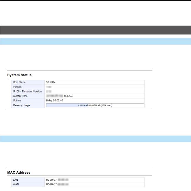
■■System Status
Displays the firmware version, Date and Time, uptime, and memory usage.
LLSee “Transceiver Management” screen in this manual for details on the firmware version of each IP100H that is registered to the RoIP server. (Transceiver Controller > Transceiver Settings > Transceiver Management)
TOP
■■MAC Address
Displays the MAC Address (LAN/WAN.)
LLThe MAC address is the peculiar number that is assigned to a networking device.
It is displayed in 12 hexadecimal (00-90-C7-XX-XX-XX).
LLThe MAC address is also printed on the label on the bottom of the RoIP gateway.
1-2
1 TOP
TOP screen
TOP
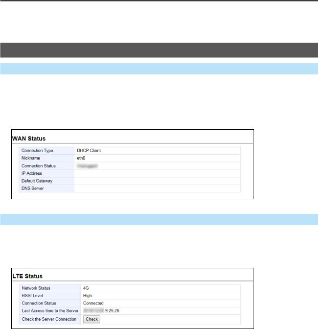
■■WAN Status
Displays the WAN connection status that is set on the “WAN” screen setting in the Router Settings menu. (Router Settings > WAN)
TOP
■■LTE Status
Displays the LTE information, such as RSSI Level, if a nanoSIM card is installed.
1
2
3
4
5
1Network Status |
Displays the type of the connected telephone line, “4G” or “3G.” |
2RSSI Level |
Displays the approximate RSSI (Received Signal Strength Indicator) |
|
level, “High,” “Middle,” “Low,” or “Out of range.” |
3Connection Status |
Displays the status of the 4G/3G line connection, “Initializing,” |
|
“Initialization failure,” “Connecting,” “Connected,” or “Disconnected.” |
4Last Access time to the Server |
Displays the last accessed date and time to the transceiver controller. |
|
LLThe date and time in the list shows the received log from the transceiver |
|
module. |
5Check the Server Connection |
Click <Check> to check the connection to the IP Transceiver controller. |
1-3

INFORMATION |
|
Section 2 |
|
|
|
Network Status screen… ……………………………………………………………………………………………… 2-2 MMInterface List……………………………………………………………………………………………………… 2-2 MMEthernet Port Connection Status………………………………………………………………………………… 2-2 MMDHCP Lease Status… …………………………………………………………………………………………… 2-2
SYSLOG screen… ……………………………………………………………………………………………………… 2-3 MMSYSLOG… ………………………………………………………………………………………………………… 2-3
Bridge Status screen… ………………………………………………………………………………………………… 2-4 MMBridge Status… …………………………………………………………………………………………………… 2-4 MMPort Connection Status… ………………………………………………………………………………………… 2-5
PBX Status screen… …………………………………………………………………………………………………… 2-6 MMExtension Group List… …………………………………………………………………………………………… 2-6 MMList of Extensions… ……………………………………………………………………………………………… 2-7
Call Log screen………………………………………………………………………………………………………… 2-8 MMCall Log…………………………………………………………………………………………………………… 2-8
Extension Status screen………………………………………………………………………………………………… 2-9 MMExtension Status…………………………………………………………………………………………………… 2-9
LTE Status screen… ………………………………………………………………………………………………… 2-10 MMLTE Module Status……………………………………………………………………………………………… 2-10 MMSIM Status… …………………………………………………………………………………………………… 2-10 MMLTE Status… …………………………………………………………………………………………………… 2-11
2-1
2 INfOrMaTION
Network Status screen
Information > Network Status
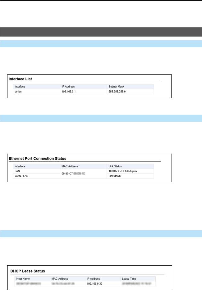
■ Interface List
Displays the details of the Interface Setting.
(Network Settings > Static routing > routing Table > Interface)
Information > Network Status
■ Ethernet Port Connection Status
Displays the transfer speed and the transfer type for the Ethernet Port.
This is an example setting the WaN connection type as [LaN Port].
TIP:
•The roIP Gateway’s [LaN] ports are auto-negotiation enabled, and can automatically select the optimal speed and duplex mode if the peer devices are auto-negotiation enabled as well.
•We recommend that you always enable auto-negotiation on the peer devices.
If a peer device is fi xed to full-duplex mode, auto-negotiation enabled devices (including the RoIP Gateway) may generally take it for half-duplex mode, and cannot communicate properly.
Information > Network Status
■ DHCP Lease Status
Displays the IP address and Lease Time assigned to the connected devices.
2-2
2 Information
SYSLOG screen
Information > SYSLOG
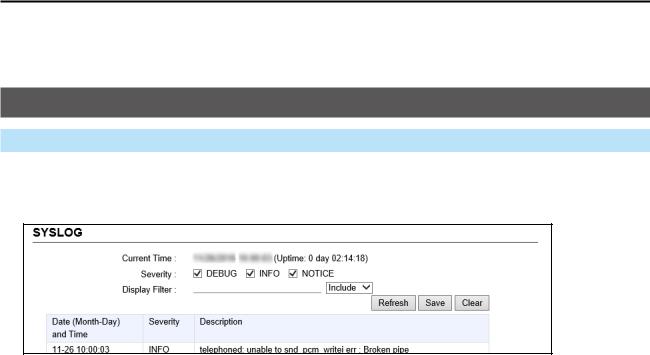
■■SYSLOG
Displays the log of the RoIP Gateway.
1 |
|
|
|
2 |
3 |
4 |
5 |
1Severity |
Select one or more log types that you want to list. |
|
|
|
LLRemove the check mark to hide the entries. |
|
|
LLThe selection is not stored, and will reset when you leave this screen. |
2Display Filter |
Enter a keyword (for example: dhcp) and select “Include” or “Exclude” |
|
|
|
to narrow down the list. |
3 |
<Refresh> |
Click to reload the list. Up to the last 1000 logs are listed. |
4 |
<Save> |
Click to save a log to a text (.txt) file. |
5 |
<Clear> |
Click to clear all the logs. |
2-3
2 Information
Bridge Status screen
Information > Bridge Status
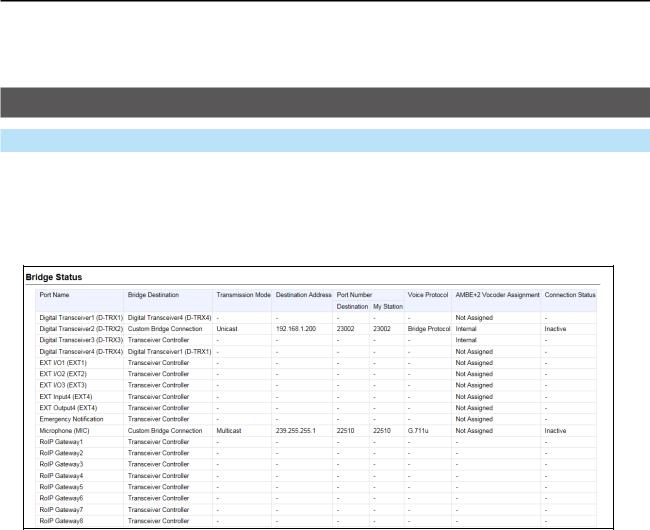
■■Bridge Status
Displays the bridge connection status list, if a bridge destination network address is set. (See also section 5 in this manual for the Bridge Connection.)
LLThe Transceiver Controller is set to each port by default.
(This is only an example.)
2-4
2 Information
Bridge Status screen
Information > Bridge Status
■■Port Connection Status
Displays the connection status of each port.
(This is only an example.)
••RoIP Gateway 1 ~ 8 displays the status of the RoIP Gateway Connection settings. (Connection Port Settings > RoIP Gateway > RoIP Gateway Connection)
••Converter Bridge 1 ~ 20 displays the status of the Connection settings. (PBX Extension > Converter Bridge > Connection)
••Voice Protocol and the AMBE+2 Vocoder Assignment display the status of the AMBE+2 Vocoder Assignment settings.
(Bridge Connection Setting > Bridge Connection > AMBE+2 Vocoder Assignment)
2-5
2 Information
PBX Status screen
Information > PBX Status
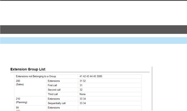
■■Extension Group List
Displays the Extension Group List status.
|
1 |
|
|
|
2 |
3 |
|||
|
|
|
|
4 |
|
|
|
|
|
|
|
|
|
|
|
|
|
|
|
1Extensions not
Belonging to a Group Displays the Extension Numbers that do not belong to any Extension
Group.
2Extension Group Number Displays the Extension Group Number and its Group Name.
3Extensions Displays the Extension Numbers that belongs to the Extension Group.
4Setting for Extension |
|
Prioritization |
Displays the prior extensions to receive a call from the Extension Group |
|
Number (2). |
2-6
2 Information
PBX Status screen
Information > PBX Status
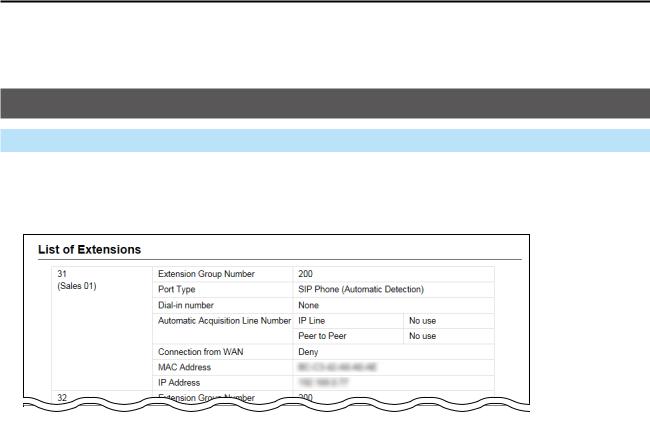
■■List of Extensions
Displays the Extension settings.
|
2 |
|
3 |
1 |
4 |
5
6
7
8
(This is only an example.)
1Extension Number |
Displays the Extension number and the name. |
|
(PBX > Extension > Extension) |
2Extension Group Number |
Displays the Extension Group number. |
|
LLDisplays “No Extension Representative” when the Extension Numbers that |
|
do not belong to any Extension Group make a call. |
3Port Type |
Displays the port type of the extension. |
4Dial-in number |
Displays the dial-in number, if entered. |
5Automatic Acquisition
Line Number Displays whether or not to automatically acquire a specific telephone
|
line. |
6Connection from WAN |
Displays whether or not to allow connecting the Extension number from |
|
the WAN. |
7MAC Address |
Displays the MAC address of the extension. |
8IP Address Displays IP Address used by the extension.
••Displays “Disconnected” when the extension does not connect to the RoIP Gateway.
••Displays “-” when you connect to the Transceiver Controller Telephone Connection or the Converter Bridge.
2-7
2 Information
Call Log screen
Information > Call Log
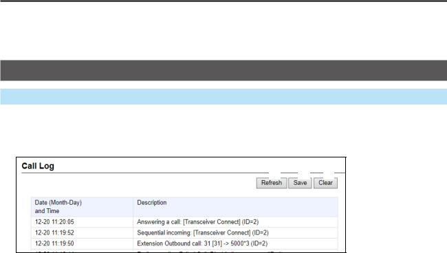
■■Call Log
Lists the log of the Bridge connection to the RoIP gateway and the telephone communication.
1 2 3
1 |
<Refresh> |
Click to reload the list. Up to the last 1000 logs are listed. |
2 |
<Save> |
Click to save a log to a text (.txt) file. |
3 |
<Clear> |
Click to delete all the logs. |
2-8
2 Information
Extension Status screen
Information > Extension Status
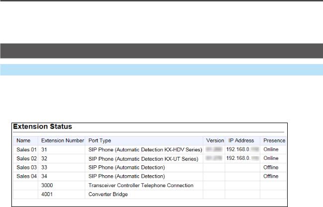
■■Extension Status
Displays the status of the Extension. (PBX > Extension > Extension)
1 |
2 |
3 |
4 |
5 |
6 |
1Name |
Displays the Extension number and the name assigned to Extension |
|
settings. |
|
(PBX > Extension > Extension) |
2Extension Number |
Displays the extension number assigned to Extension. |
|
(PBX > Extension > Extension) |
3Port Type |
Displays the port type of the extension assigned to Extension settings. |
|
(PBX > Extension > Extension). |
4Version |
Displays the Firmware information for VoIP Expansion. |
|
LLDisplayed when a SIP phone is displayed to only the Port Type |
|
Setting(3). |
5IP Address |
Displays the IP Address used by VoIP Expansion. |
|
LLDisplayed when a SIP phone is displayed to only the Port Type |
|
Setting(3). |
6Presence Displays the status of the VoIP Expansion. Not registered. Registered.
••On the phone*: Calling or holding.
••Step out*: Call forwarding except for the transceivers.
*Online, On the phone, and Step out is displayed when successfully registered. LLDisplayed when a SIP phone is displayed to only the Port Type Setting(3).
2-9
2 Information
LTE Status screen
Information > LTE Status
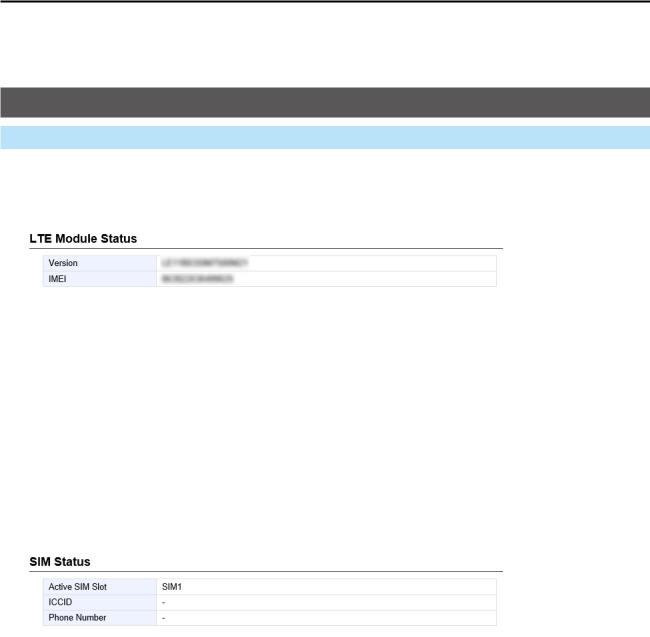
■■LTE Module Status
Displays the information of the LTE communication module.
|
1 |
|
|
|
2 |
|
|
|
|
|
|
1Version |
Displays the version of the LTE communication module. |
||
2IMEI |
Displays the communication module’s IMEI (International Mobile |
||
|
|
Equipment Identifier.) |
|
|
|
|
|
Information > LTE Status |
|
|
|
■■SIM Status |
|
|
|
Displays the information of the SIM. |
|
|
|
|
|
|
|
|
1 |
|
|
|
2 |
|
|
|
3 |
|
|
|
|
|
|
1Active SIM Slot |
Displays the SIM slot number in use. |
||
2ICCID |
Displays the ICCID (IC Card IDentifier) of the installed SIM card. |
||
|
|
LLDisplayed when information of Active SIM Slot Setting (1) can be acquired. |
|
3Phone Number |
Displays the telephone number of the SIM card. |
||
|
|
LLDisplayed when information of Active SIM Slot Setting (1) can be acquired. |
|
2-10
2 Information
LTE Status screen
Information > LTE Status
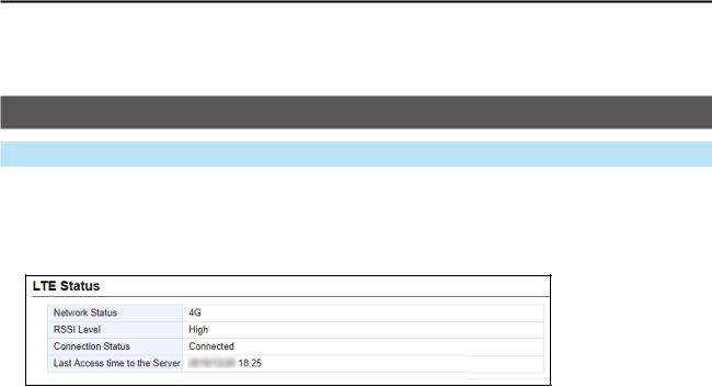
■■LTE Status
Displays the information of the LTE line if installed and valid.
1
2
3
4
1Network Status |
Displays the type of the connected telephone line, “4G” or “3G.” |
2RSSI Level |
Displays the approximate RSSI level, “High,” “Middle,” “Low,” or “Out of |
|
range.” |
3Connection Status |
Displays the status of the 4G/3G line connection, “Initializing,” |
|
“Initialization failure,” “Connecting,” “Connected,” or “Disconnected.” |
4Last Access time to |
|
the Server |
Displays the last accessed date and time to the IP transceiver controller. |
|
LLThe date and time in the list displayed here are acquired from the transceiver |
|
module. |
2-11

NETWORK SETTINGS |
|
Section 3 |
|
|
|
IP Address screen… …………………………………………………………………………………………………… 3-2 MMHost Name… ……………………………………………………………………………………………………… 3-2 MMIP Address… ……………………………………………………………………………………………………… 3-3
DHCP Server screen… ………………………………………………………………………………………………… 3-4 MMDHCP Server… …………………………………………………………………………………………………… 3-4 MMStatic DHCP………………………………………………………………………………………………………… 3-7 MMList of Static DHCP Settings……………………………………………………………………………………… 3-7
Static Routing Screen…………………………………………………………………………………………………… 3-8 MMRouting Table… …………………………………………………………………………………………………… 3-8 MMStatic Routing… …………………………………………………………………………………………………… 3-9 MMList of Static Routing Entries……………………………………………………………………………………… 3-9
Policy Routing screen………………………………………………………………………………………………… 3-10 MMSource Address Routing… …………………………………………………………………………………… 3-10 MMList of Source Address Routing Entries… …………………………………………………………………… 3-10
3-1
3 Network Settings
IP Address screen
Network Settings > IP Address
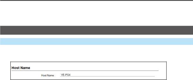
■■Host Name
Enter the host name.
Host Name Enter a host name of up to 31 characters. (Default: VE-PG4) When the RoIP Gateway connects to Telnet/SSH, this host name is displayed.
LLThe usable characters are: “a” ~ “z”, “A” ~ “Z”, “0” ~ “9”, and “-.”
LLThe name must start with an alphanumeric character, and must NOT start or end with a “–.”
3-2
3 Network Settings
IP Address screen
Network Settings > IP Address
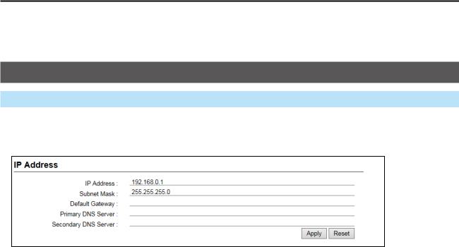
■■IP Address
Enter the VE-PG4’s IP Address.
1 |
|
|
2 |
|
|
3 |
|
|
4 |
|
|
5 |
6 |
7 |
1IP Address |
Enter the LAN IP address according to your network environment. |
|
|
|
(Default: 192.168.0.1) |
|
|
LLWhen using the DHCP Server function, the network part of the IP address |
|
|
must be the same as that set in the “IP Pool Start Address” item in the |
|
|
[DHCP Server] menu. |
2Subnet Mask |
Enter the subnet mask according to your network environment. |
|
|
|
(Default: 255.255.255.0) |
3Default Gateway |
If a default gateway device, such as a router, is connected to the LAN |
|
|
|
port, enter the device’s IP address. |
4Primary DNS Server |
Enter the DNS server address specified by your service provider. |
|
|
|
If you have two DNS server addresses, enter the primary address. |
5Secondary DNS Server |
If you have two DNS server addresses, enter the secondary DNS |
|
|
|
server address. |
6<Apply> |
|
Click to apply the entries. |
7<Reset> |
|
Click to reset the settings. |
|
|
LLYou cannot reset after clicking <Apply>. |
3-3
3 Network Settings
DHCP Server screen
Network Settings > DHCP Server
■■DHCP Server
Configure the DHCP Server function.
1
2
3
4
5
6
7
1DHCP Server |
Select “Enable” to use the DHCP Server function. |
(Default: Disable) |
|
|
The DHCP Sever is activated, depending on the IP Pool Start Address |
||
|
(2) and Pool Size (3) items. |
|
|
2IP Pool Start Address |
Enter the IP Pool Start address. |
(Default: 192.168.0.10) |
|
|
An IP address is automatically assigned to a transceiver that the RoIP |
||
|
Gateway connects to, from this IP Pool Start address. |
|
|
3Pool Size |
Entry the number of an IP address that can be automatically assigned. |
||
|
|
|
(Default: 30) |
|
Up to 128 addresses can be automatically assigned by the DHCP |
||
|
server function. Another 32 addresses can be manually assigned. |
||
4Subnet Mask |
Enter the subnet mask for the IP Pool Start address set in the “IP Pool |
||
|
Start Address” (2). |
(Default: 255.255.255.0) |
|
5Lease Time |
Enter the lease time period. |
|
(Default: 72) |
|
Range: 1 ~ 9999 (hours) |
|
|
6Domain Name |
Enter a network address domain name of up to 253 characters. |
||
7Default Gateway |
Enter the default gateway IP address. |
|
|
|
When the DHCP Server function is used, this IP address is sent to a |
||
|
client. |
|
|
|
LLWhen this item is blank, the RoIP Gateway’s IP address is sent. |
||
3-4
3 Network Settings
DHCP Server screen
Network Settings > DHCP Server
■■DHCP Server
8
9
10
11
12
13
14 15 16
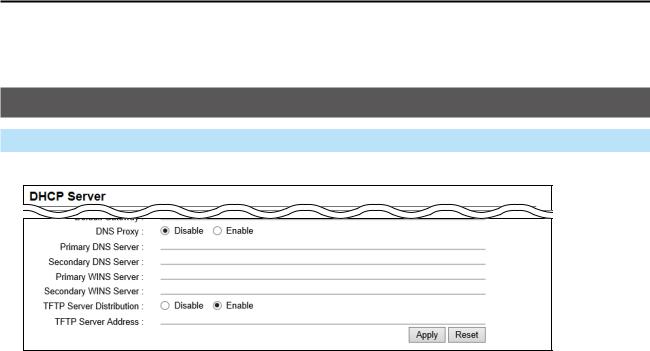
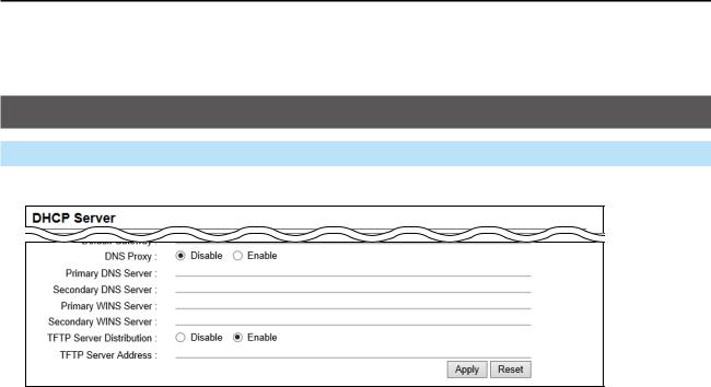
The screen above shows when “DNS Proxy” (8) is set to “Disable.”
8DNS Proxy |
Selects whether or not to use a DNS proxy. |
(Default: Enable) |
|
When this option is set to “Enable,” the terminals can assign the RoIP |
|
|
Gateway as the DNS server. |
|
9Primary DNS Server |
(Displayed only when the DNS Proxy (8) is disabled) |
|
|
Enter the DNS server address specified by your service provider. |
|
|
If you have two DNS server addresses, enter the primary address. |
|
10Secondary DNS Server |
(Displayed only when the DNS Proxy (8) is disabled) |
|
|
If you have two DNS server addresses, enter the secondary DNS |
|
|
server address. |
|
11Primary WINS Server |
Enter the WINS server’s address. If you have two WINS server |
|
|
addresses, enter the primary address. |
|
12Secondary WINS Server |
If you have two WINS server addresses, enter the WINS server’s |
|
|
secondary address. |
|
3-5
3 Network Settings
DHCP Server screen
Network Settings > DHCP Server
■■DHCP Server
8
9
10
11
12
13
14 15 16
The screen above shows when “DNS Proxy” (8) is set to “Disable.”
13TFTP Server Distribution |
Set to “Enable” to use a provisioning KX Series telephone. |
|
|
|
(Default: Enable) |
|
|
When this option is enabled, the telephone automatically reads the |
|
|
setting from the RoIP Gateway and sets up by itself. |
|
|
LLThe telephone’s MAC address must be entered on the “Extension” screen. |
|
|
LLWhen using this system with static IP addresses, see also Section 4 in the |
|
|
Installation guide. |
14TFTP Server Address |
Enter the IP address of the TFTP server for the KX series telephone. |
|
|
|
If this item is blank, the RoIP Gateway works as theTFTP server. |
|
|
(Default: Blank) |
15<Apply> |
|
Click to apply the entries. |
16<Reset> |
|
Click to reset the settings. |
|
|
LLYou cannot reset after clicking <Apply>. |
3-6
3 Network Settings
DHCP Server screen
Network Settings > DHCP Server
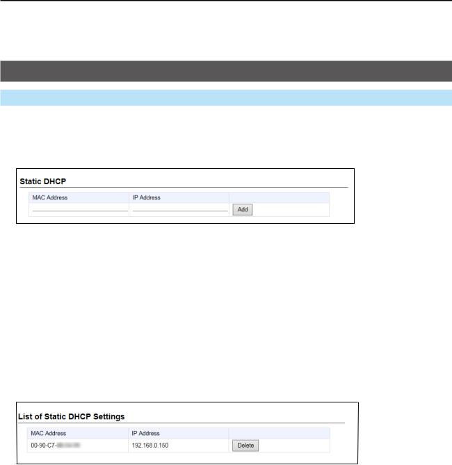
■■Static DHCP
Enter the MAC and static IP addresses of the DHCP server.
LLYou can enter up to 32 entries.
Static DHCP |
Enter the MAC and IP addresses, and then click <Add>. |
|
LLThis setting is useful when the DHCP Server function is used. See page 3-4 |
|
for details of the DHCP Server function. |
|
LLSets a different IP address from the IP address that the DHCP Server |
|
function automatically assigns. |
|
LLMake sure that the addresses of the devices on the network do not overlap |
|
or conflict. |
|
If a DHCP server is already connected to the network, and there is an |
|
address conflict, a network problem will occur. |
■■List of Static DHCP Settings
Displays the static DHCP entries.
<Delete> |
Click to delete the entry. |
|
LLYou cannot restore after clicking <Delete>. |
3-7
3 Network Settings
Static Routing Screen
Network Settings > Static Routing
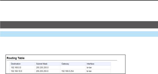
■■Routing Table
Displays the valid routing information for packet transmission.
1 2 3 4
1Destination |
The network address of the route’s destination network. |
|
2Subnet Mask |
The subnet mask of the route’s destination network. |
|
3Gateway |
The route’s gateway address. |
|
4Interface |
The routing interface. |
|
|
•• br-lan: |
LAN |
|
•• eth0: |
WAN |
|
•• ppp0 ~ ppp7: |
PPPoE (WAN) |
|
•• vti0 ~ vti 31: |
IPsec Tunnel |
3-8
3 Network Settings
Static Routing Screen
Network Settings > Static Routing
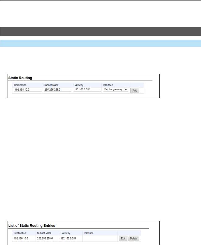
■■Static Routing
Enter the static routing destinations.
LLYou can enter up to 32 entries.
1 |
2 |
3 |
4 |
5 |
|
|
|
|
1Destination |
The network address of the route’s destination network. |
2Subnet Mask |
The subnet mask of the route’s destination network. |
3Gateway |
(Only when the Interface (4) is set to “Set the gateway”) |
|
Set the route’s gateway address. |
4Interface |
The routing interface. |
|
•• Set the gateway |
|
•• ppp0 (WAN01) ~ ppp7 (WAN08) |
|
•• vti0 ~ vti 31 |
5<Add> |
Click to add the entry. |
|
The entry that is registered in the [List of Static Routing Entries] is |
|
displayed. |
■■List of Static Routing Entries
Displays the static routing destinations.
LLYou can enter up to 32 entries.
1 2
1 |
<Edit> |
Click to edit the entry. |
2 |
<Delete> |
Click to delete the entry. |
|
|
LLYou cannot restore after clicking <Delete>. |
3-9
3 Network Settings
Policy Routing screen
Network Settings > Policy Routing
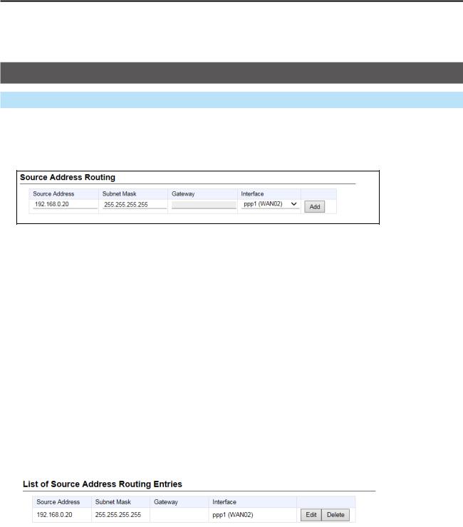
■■Source Address Routing
Enter the packet source routing from the specified network address of the source terminal (such as a PC.)
LLYou can enter up to 32 entries.
1 |
2 |
3 |
4 |
5 |
|
|
|
|
1Source Address |
Set the network address of the source terminal. |
2Subnet Mask |
Set the subnet mask of the source network address. |
3Gateway |
(Only when the Interface (4) is set to “Set the gateway”) |
|
Set the route’s gateway address. |
4Interface |
The routing target interface from: |
|
•• Set the gateway |
|
•• ppp0 (WAN01) ~ ppp7 (WAN08) |
|
•• vti0 ~ vti31 |
5<Add> |
Click to add the entry. |
|
The entry that is registered in the [List of Source Address Routing |
|
Entries] is displayed. |
■■List of Source Address Routing Entries
Displays the entered packet source routing settings.
|
|
|
1 |
2 |
|
|
|
|
|
1 |
<Edit> |
Click to edit the entry. |
|
|
2 |
<Delete> |
Click to delete the entry. |
|
|
|
|
|
LLYou cannot restore after clicking <Delete>. |
|
3-10

ROUTER SETTINGS |
|
Section 4 |
|
|
|
WAN screen… …………………………………………………………………………………………………………… 4-2 MMConnection Status… ……………………………………………………………………………………………… 4-2 MMConnection Type…………………………………………………………………………………………………… 4-6 MMConnection Settings… …………………………………………………………………………………………… 4-7 MMList of Connection Settings… ………………………………………………………………………………… 4-12
NAT screen… ………………………………………………………………………………………………………… 4-13 MMNAT… …………………………………………………………………………………………………………… 4-13 MMDMZ Host………………………………………………………………………………………………………… 4-13 MMPort Forwarding… ……………………………………………………………………………………………… 4-14 MMList of Port Forwarding Entries………………………………………………………………………………… 4-15
IP Filter screen………………………………………………………………………………………………………… 4-16 MMGeneral Settings………………………………………………………………………………………………… 4-16 MMIP Filter…………………………………………………………………………………………………………… 4-17 MMList of IP Filter Entries… ……………………………………………………………………………………… 4-22
Simple DNS screen…………………………………………………………………………………………………… 4-23 MMSimple DNS Server Setting… ………………………………………………………………………………… 4-23 MMList of Simple DNS Server Settings…………………………………………………………………………… 4-23
VPN screen… ………………………………………………………………………………………………………… 4-24 MMIPsec Settings…………………………………………………………………………………………………… 4-24 MMIPsec Tunnel Settings………………………………………………………………………………………… 4-25 MMList of IPsec Tunnel Settings…………………………………………………………………………………… 4-27
4-1
4 Router Settings
WAN screen
Router Settings > WAN
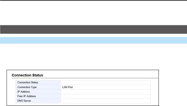
■■Connection Status
(When “Connection Type” is set to “LAN port”) The WAN connection status is displayed.
1
2
3
4
5
1Connection Status |
Nothing is displayed. |
2Connection Type |
The WAN connection type is displayed. |
3IP Address |
Nothing is displayed. |
4Peer IP Address |
Nothing is displayed. |
5DNS Server |
Nothing is displayed. |
4-2
4 Router Settings
WAN screen
Router Settings > WAN
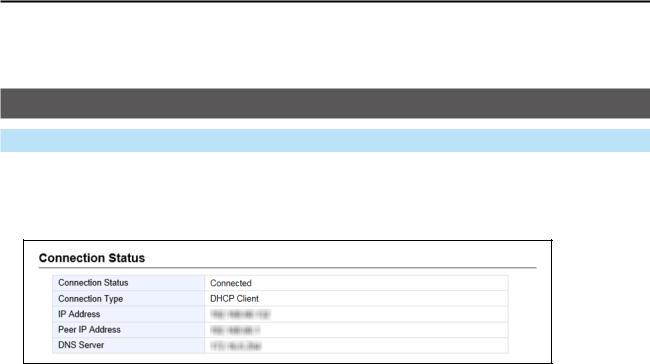
■■Connection Status
(When “Connection Type” is set to “DHCP Client”) The WAN connection status is displayed.
1
2
3
4
5
1Connection Status |
The connection status to the Internet line is displayed as “Unplugged,” |
|
“Connecting,” or “Connected.” |
2Connection Type |
The WAN connection type is displayed. |
3IP Address |
The RoIP Gateway’s IP address is displayed. |
4Peer IP Address |
The default Gateway IP address specified by your service provider is |
|
displayed. |
5DNS Server |
The DNS server’s IP address is displayed. |
4-3
 Loading...