


 Loading...
IBM 2256, 6346, 6342, 6347, 6337 User Manual
...IBM |
|
Hardware Maintenance Manual
Types 2254, 2256, 2257, 6336, 6337, 6339, 6341, 6342, 6346, 6347, 6348
IBM |
|
Hardware Maintenance Manual
Types 2254, 2256, 2257, 6336, 6337, 6339, 6341, 6342, 6346, 6347, 6348

Note:
Before using this information and the product it supports, be sure to read the general information un
First Edition (July 2001)
The following paragraph does not apply to the United Kingdom or any country where such provisions are inconsistent with local law:
INTERNATIONAL BUSINESS MACHINES CORPORATION PROVIDES THIS PUBLICATION ″AS IS″ WITHOUT ANY WARRANTY OF ANY KIND, EITHER EXPRESS OR IMPLIED, INCLUDING, BUT NOT LIMITED TO, THE LIMITED WARRANTIES OF MERCHANTABILITY OR FITNESS FOR A PARTICULAR PURPOSE. Some states do not allow disclaimers or express or implied warranties in certain transactions; therefore, this statement may not apply to you.
This publication could include technical inaccuracies or typographical errors. Changes are periodically made to the information herein; these changes will be incorporated in new editions of the publication. IBM may make improvements or changes in the products or the programs described in this publication at any time.
Requests for technical information about IBM products should be made to your IBM Authorized Dealer or your IBM Marketing Representative.
© Copyright International Business Machines Corporation 2000. All rights reserved.
US Government Users Restricted Rights – Use, duplication or disclosure restricted by GSA ADP Schedule Contract with IBM Corp.
About this manual
This manual contains service and reference information for the IBM® computer
Types 2254, 2256, 2257, 6336, 6337, 6339, 6341, 6342, 6436, 6347, 6348.
This manual is divided into product service sections (by machine chassis) and a related service section, as follows:
vThe product service sections include procedures for isolating problems to a FRU, a Symptom-to-FRU Index, additional service information and an illustrated parts catalog.
vThe related service section includes safety notices and safety information, and problem determination tips.
Note:
This manual is intended for trained servicers who are familiar with IBM Personal Computer products. Use this manual along with advanced diagnostic tests to troubleshoot problems effectively.
Before servicing an IBM product, be sure to review the “Safety notices (multi-lingual translations)” on page 211 and “Safety information” on page 207.
Important Safety Information
Be sure to read all caution and danger statements in this book before performing any of the instructions.
Prenez connaissance de toutes les consignes de type Attention et Danger avant de procéder aux opérations décrites par les instructions.
Lesen Sie alle Sicherheitshinweise, bevor Sie eine Anweisung ausführen.
Accertarsi di leggere tutti gli avvisi di attenzione e di pericolo prima di effettuare qualsiasi operazione.
© Copyright IBM Corp. 2000 |
iii |

Leia todas as instruções de cuidado e perigo antes de executar qualquer operação.
Lea atentamente todas las declaraciones de precaución y peligro ante de llevar a cabo cualquier operación.
iv Hardware Maintenance Manual

Contents
About this manual . . . . . . . . . . iii
Important Safety Information . . . . . . . . iii
Chapter 1. General Checkout. . . . . . 1
Chapter 2. General Information . . . . . 3
Features . . . . . . . . . . . . . . . . 3 Specifications . . . . . . . . . . . . . . 5 Physical specification — small desktop model . . 5 Physical specification — desktop model . . . . 6 Physical specifications — microtower model . . . 7
Chapter 3. Diagnostics . . . . . . |
. |
. |
9 |
Setup Utility program . . . . . . . . . |
. |
. |
10 |
Product Recovery Program menu . . . . . |
. |
. 11 |
|
Diagnostics . . . . . . . . . . . . . . 12 |
|||
Diagnostics program download. . . . . |
. |
. 12 |
|
Navigating through the diagnostics programs . . 12 |
|||
Running diagnostics tests. . . . . . . |
. |
. |
12 |
Test selection . . . . . . . . . . . |
. |
. |
12 |
Module test menu/hardware configuration report 13 |
|||
Memory Diagnostic tests . . . . . . . |
. |
. |
13 |
Alert-On LAN™ test . . . . . . . . |
. |
. |
14 |
Asset ID™ test . . . . . . . . . . |
. |
. |
14 |
Test results . . . . . . . . . . . |
. |
. |
14 |
Hard file Smart test. . . . . . . . . |
. |
. |
15 |
Quick and Full erase - hard drive . . . . |
. |
. 15 |
|
Iomega Zip drive test . . . . . . . . |
. |
. |
16 |
Asset EEPROM backup . . . . . . . |
. |
. 16 |
|
Viewing the test log . . . . . . . . |
. |
. |
16 |
When to use the Low-Level Format program . |
. |
. 17 |
|
Preparing the hard disk drive for use. . . . |
. |
. |
17 |
Chapter 4. Installing Options . . . . . 19
Locating the connectors on the front of your
computer . . . . . . . . . . . . . . . 19
Locating the connectors on the rear of your |
|
|
|
|
computer . . . . . . . . . . . . |
. |
. |
. |
22 |
Home PNA network adapter . . . . |
. |
. |
. |
25 |
Removing the cover - small desktop model . . . . 26
Locating components - small desktop model . . |
. 27 |
|
Identifying parts on the system board - small |
|
|
desktop model . . . . . . . . . . . . |
. |
27 |
Installing memory - small desktop model . . . |
. 28 |
|
Installing DIMMs . . . . . . . . . . |
. |
28 |
Installing adapters - small desktop model . . . |
. 29 |
|
Installing internal drives - small desktop model . |
. 30 |
|
Drive specifications . . . . . . . . . . |
. |
30 |
Installing a drive . . . . . . . . . . |
. |
31 |
Installing a Rope Clip - small desktop model . . |
. 33 |
|
Replacing the cover and connecting the cables - |
|
|
small desktop model . . . . . . . . . . |
. |
33 |
Removing the cover - desktop model . . . . . |
. 34 |
|
Locating components - desktop model . . . . |
. 35 |
|
Identifying parts on the system board - desktop
model . . . . . . . . . . . . . . . . 35
Installing memory - desktop model . . . . . |
. 36 |
|
Installing DIMMs . . . . . . . . . . |
. |
36 |
Installing adapters - desktop model . . . . . |
. |
37 |
Installing internal drives - desktop model . . . |
. 38 |
|
Drive specifications . . . . . . . . . . |
. |
39 |
Installing a drive . . . . . . . . . . |
. |
40 |
Installing a Rope Clip - desktop model . . . . |
. 42 |
|
Replacing the cover and connecting the cables - |
|
|
desktop model . . . . . . . . . . . . |
. |
43 |
Removing the cover - microtower model . . . |
. 44 |
|
Locating components - microtower model . . . |
. 46 |
|
Moving the power supply - microtower model . |
. 46 |
|
Identifying parts on the system board - microtower model . . . . . . . . . . . . . . . . 48
Installing memory - microtower model . . . . |
. 49 |
|
Installing DIMMs . . . . . . . . . . |
. |
49 |
Installing adapters - microtower model . . . . |
. 50 |
|
Installing internal drives - microtower model . . |
. 51 |
|
Drive specifications . . . . . . . . . . |
. |
52 |
Installing a drive . . . . . . . . . . |
. |
53 |
Installing a Rope Clip - microtower model . . . |
. 55 |
|
Replacing the cover and connecting the cables - |
|
|
microtower model . . . . . . . . . . . |
. |
56 |
Chapter 5. FRU Replacements. . . . |
. 59 |
Identifying parts on the system board . . . . |
. 59 |
Replacing a System Board - Small Desktop Model |
60 |
Replacing a processor - Small Desktop Model . . |
. 61 |
Power supply removal - Small Desktop Model . |
. 62 |
Replacing a System Board - Desktop Model . . |
. 62 |
Replacing a processor - Desktop Model . . . . |
. 63 |
Power supply removal - Desktop Model . . . . |
. 64 |
Replacing a system board - Microtower Model . |
. 65 |
Replacing a processor - Microtower Model . . . |
. 66 |
Power supply removal - Microtower Model . . |
. 66 |
Chapter 6. Symptom-to-FRU Index . . |
. 69 |
||
SDRAM memory errors . . . . . . . . |
. |
. 70 |
|
Hard disk drive boot error . . . . . . . |
. |
. |
70 |
Power Supply Errors . . . . . . . . . |
. |
. |
71 |
Diagnostic error codes . . . . . . . . . |
. |
. |
72 |
Beep symptoms . . . . . . . . . . . |
. |
. |
90 |
No-beep symptoms . . . . . . . . . . |
. |
. |
92 |
POST error codes . . . . . . . . . . |
. |
. |
93 |
Miscellaneous error messages . . . . . . . |
. |
|
107 |
Undetermined problems . . . . . . . . . |
. |
|
109 |
Chapter 7. Parts . . . . . . . . . . 111
Small Desktop Model . . . . . . . . . . . 111 Desktop Model . . . . . . . . . . . . . 137 Microtower Model. . . . . . . . . . . . 159
© Copyright IBM Corp. 2000 |
v |
Chapter 8. Additional Service
Information . . . . . . . . . . . . 197
Security features . . . . . . . . . . . |
. |
197 |
Passwords . . . . . . . . . . . . |
. |
197 |
Vital product data . . . . . . . . . . |
. |
198 |
Management Information Format (MIF) . . |
. 198 |
|
Alert on LAN . . . . . . . . . . . |
. |
199 |
BIOS levels . . . . . . . . . . . . . |
. |
199 |
Flash (BIOS/VPD) update procedure . . . . |
. 200 |
|
Flash recovery boot block jumper. . . . . . |
. 200 |
|
Power management . . . . . . . . . . |
. |
202 |
Automatic configuration and power interface |
|
|
(ACPI) BIOS. . . . . . . . . . . . |
. |
202 |
Advanced Power Management . . . . . |
. 202 |
|
Automatic Hardware Power Management |
|
|
features . . . . . . . . . . . . . |
. |
202 |
Setting Automatic Hardware Power |
|
|
Management features. . . . . . . . . |
. |
203 |
Automatic Power-On features . . . . . . |
. 203 |
|
Network settings . . . . . . . . . . . . 204 Flash over LAN (update POST/BIOS over
network) . . . . . . . . . . . . . . 204 Wake on LAN . . . . . . . . . . . . 205
Chapter 9. Related service information |
207 |
|
Safety information. . . . . . . . . . . |
. |
207 |
General safety . . . . . . . . . . . |
. |
207 |
Electrical safety. . . . . . . . . . . |
. |
208 |
Safety inspection guide . . . . . . . . |
. |
209 |
Handling electrostatic discharge-sensitive
devices . . . . . . . . . . . . . . 210
Grounding requirements. . . . . . . |
. |
. |
211 |
Safety notices (multi-lingual translations) . |
. |
. |
211 |
Send us your comments! . . . . . . . |
. |
. 240 |
|
Problem determination tips. . . . . . . |
. |
. |
241 |
Notices . . . . . . . . . . . . . . . 241 |
|||
Trademarks . . . . . . . . . . . . |
. |
. |
242 |
vi Hardware Maintenance Manual

Chapter 1. General Checkout
This general checkout procedure is for Types 2254, 2256, 2257, 6336, 6337, 6339, 6341, 6342, 6346, 6347, and 6348 computers.
Attention:
The drives in the computer you are servicing might have been rearranged or the drive startup sequence changed. Be extremely careful during write operations such as copying, saving or formatting. Data or programs can be overwritten if you select an incorrect drive.
Diagnostic error messages appear when a test program finds a problem with a hardware option. For the test programs to properly determine if a test Passed, Failed or Aborted, the test programs check the error-return code at test completion. See “Diagnostics” on page 12.
General error messages appear if a problem or conflict is found by an application program, the operating system, or both. For an explanation of these messages, refer to the information supplied with that software package.
Notes:
vTypes 2254, 2256, 2257, 6336, 6337, 6339, 6341, 6342, 6346, 6347, and 6348 computers default to come up quiet (no beep and no memory count and checkpoint code display) when no errors are detected by POST.
vTo enable beep and memory count and checkpoint code display when a successful POST occurs, do the following:
1.Select Start Options in the Configuration/Setup Utility program (see “Setup Utility program” on page 10).
2.Set Power-On Self-Test to Enhanced.
vBefore replacing any FRUs, ensure that the latest level of BIOS is installed on the system. A down-level BIOS might cause false errors and unnecessary replacement of the system board. For more information on how to determine and obtain the latest level BIOS, see “BIOS levels” on page 199.
vIf multiple error codes are displayed, diagnose the first error code displayed.
vIf the computer hangs with a POST error, go to ″Symptom-to-FRU Index″ on page 69.
vIf the computer hangs and no error is displayed, go to “Undetermined problems” on page 109.
vIf an installed device is not recognized by the diagnostics program, that device might be defective.
001
1.Power-off the computer and all external devices.
2.Check all cables and power cords.
3.Make sure the system board is seated properly.
4.Set all display controls to the middle position.
5.Power-on all external devices.
6.Power-on the computer.
7.Check for the following response:
v Readable instructions or the Main Menu.
© Copyright IBM Corp. 2000 |
1 |
DID YOU RECEIVE THE CORRECT RESPONSE?
If NO, continue to 002 .
If YES, proceed to 003 .
002
If the Power Management feature is enabled, do the following:
1.Start the Configuration/Setup Utility program (see “Setup Utility program” on page 10)
2.Select Power Management from the Configuration/Setup Utility program menu.
3.Select APM.
4.Be sure APM BIOS Mode is set to Disabled. If it is not, press Left Arrow (}) or Right Arrow (Æ) to change the setting.
5.Select Automatic Hardware Power Management.
6.Set Automatic Hardware Power Management to Disabled.
7.If the problem persists, continue to 003 .
003
Run the Diagnostic programs. If necessary, refer to “Diagnostics” on page 12.
vIf you receive an error, replace the part that the diagnostic program calls out or go to ″Symptom-to-FRU Index″ on page 69.
vIf the test stops and you cannot continue, replace the last device tested.
2 Hardware Maintenance Manual
Chapter 2. General Information
Features
This section provides an overview of the computer features, preinstalled software, and specifications.
Microprocessor
Intel® Pentium™ III with 256 KB of internal L2 cache memory and MMX™ technology or an Intel Celeron™ with 256 KB of internal L2 cache memory and MMX technology
Memory
vSupport for two dual in-line memory modules (DIMMs)
v512 KB flash memory for system programs
Internal drives
v3.5-inch, 1.44 MB diskette drive (some models)
vInternal hard disk drive
vEIDE CD drive or DVD drive (some models)
Video controller
Dynamic video memory technology
Audio subsystem
16-bit integrated Sound Blaster Pro compatible audio subsystem
Connectivity
v10/100 Mbps integrated Intel ethernet controller that supports the Wake on LAN® feature
vModem (some models)
System management features
vRemote Program Load (RPL) and Dynamic Host Configuration Protocol (DHCP)
vWake on LAN
vWake on Ring (in the Configuration/Setup Utility program, this feature is called Serial Port Ring Detect for an external modem and Modem Ring Detect for an internal modem)
vRemote Administration
vAutomatic power-on startup
vSystem Management (SM) BIOS and SM software
vAbility to store POST hardware test results
Input/output features
v25-pin, Extended Capabilities Port (ECP)/Extended Parallel Port (EPP)
vTwo 9-pin serial connectors
vFour 4-pin, USB connectors
vPS/2® mouse connector
© Copyright IBM Corp. 2000 |
3 |

vPS/2 keyboard connector
vEthernet connector
vMonitor connector
vThree audio connectors (line in, line out, and microphone)
vFront connectors on some small desktops (S/PDIF, microphone, and headphone)
vFront IEEE 1394 connector (some small desktop models)
Expansion
vDrive bays
–Small desktop model: Three
–Desktop model: Four
–Microtower model: Four
v32-bit PCI expansion slots
–Small desktop model: Three (expansion cards must be low profile)
–Desktop model: Three
–Microtower model: Three
Power
v95 W, 120 W, or 155 W power supply with manual voltage selection switch
vAutomatic 50/60 Hz input frequency switching
vAdvanced Power Management support
vAdvanced Configuration and Power Interface (ACPI) support
Security features
vPower-on and administrator passwords
vSupport for the addition of a Rope Clip and lockable cable (varies by mechanical chassis)
vStartup sequence control
vStartup without diskette drive, keyboard, or mouse
vUnattended start mode
vDiskette and hard disk I/O control
vSerial and parallel port I/O control
vSecurity profile by device
IBM preinstalled software
Your computer might come with preinstalled software. If it does, an operating system, device drivers to support built-in features, and other support programs are included.
Operating systems (supported)
vMicrosoft® Windows® Millennium Edition (Me)
vMicrosoft Windows 2000 Professional
vMicrosoft Windows 98 Second Edition
Operating systems (tested for compatibility)1
1.The operating systems listed here are being tested for compatibility at the time this publication goes to press. Additional operating systems might be identified by IBM as compatible with your computer following the publication of this booklet. Corrections and additions to this list are subject to change. To determine if an operating system has been tested for compatibility, check the Web site of the operating system vendor.
4 Hardware Maintenance Manual

vMicrosoft Windows 95
vMicrosoft Windows NT® Workstation Version 4.0
vMicrosoft Windows XP Personal and Professional
Specifications
This section lists the physical specifications for your computer.
Physical specification — small desktop model
Dimensions
Height: 88 mm (3.4 in.)
Width: 305 mm (12.0 in.)
Depth: 380 mm (14.9 in.)
Weight
Minimum configuration as shipped: 8.5 kg (18 lb)
Maximum configuration: 8.6 kg (19 lb)
Environment
Air temperature:
System on: 10° to 35° C (50° to 95° F)
System off: 10° to 43° C (50° to 110° F)
Maximum altitude: 2134 m (7000 ft)
Note: The maximum altitude, 2134 m (7000 ft), is the maximum altitude at which the specified air temperatures apply. At higher altitudes, the maximum air temperatures are lower than those specified.
Humidity:
System on: 8% to 80%
System off: 8% to 80%
Electrical input
Input voltage:
Low range:
Minimum: 90 V ac
Maximum: 137 V ac
Input frequency range: 57–63 Hz
Voltage switch setting: 115 V ac
High range:
Minimum: 180 V ac
Maximum: 265 V ac
Input frequency range: 47–53 Hz
Voltage switch setting: 230 V ac
Input kilovolt-amperes (kVA) (approximate):
Minimum configuration as shipped: 0.08 kVA
Maximum configuration: 0.30 kVA
Note: Power consumption and heat output vary depending on the number and type of optional features installed and the power-management optional features in use.
Heat output (approximate) in British thermal units (Btu) per hour:
Minimum configuration: 188 Btu/hr (55 watts)
Maximum configuration: 256 Btu/hr (75 watts)
Airflow
Approximately 0.25 cubic meters per minute (9 cubic feet per minute) maximum
Acoustical noise-emission values
Average sound-pressure levels:
At operator position:
Idle: 38 dBA
Operating: 43 dBA
At bystander position - 1 meter (3.3 ft):
Idle: 33 dBA
Operating: 37 dBA
Declared (upper limit) sound-power levels:
Idle: 3.75 bels
Operating: 4.99 bels
Note: These levels were measured in controlled acoustical environments according to the procedures specified by the American National Standards Institute (ANSI) S12.10 and ISO 7779 and are reported in accordance with ISO 9296. Actual sound-pressure levels in a given location might exceed the average values stated because of room reflections and other nearby noise sources. The declared sound-power levels indicate an upper limit, below which a large number of computers will operate.
Note: The computer is classified as a Class A or Class B digital device. See the Quick Reference for further information about this classification.
Chapter 2. General Information 5

Physical specification — desktop model
Dimensions
Height: 140 mm (5.5 in.)
Width: 425 mm (16.7 in.)
Depth: 425 mm (16.7 in)
Weight
Minimum configuration as shipped: 14.0 kg (30 lb)
Maximum configuration: 17.3 kg (25.0 lb)
Environment
Air temperature:
System on: 10° to 35° C (50° to 95° F)
System off: 10° to 43° C (50° to 110° F)
Maximum altitude: 2134 m (7000 ft)
Note: The maximum altitude, 2134 m (7000 ft), is the maximum altitude at which the specified air temperatures apply. At higher altitudes, the maximum air temperatures are lower than those specified.
Humidity:
System on: 8% to 80%
System off: 8% to 80%
Electrical input
Input voltage:
Low range:
Minimum: 90 V ac
Maximum: 137 V ac
Input frequency range: 57–63 Hz
Voltage switch setting: 115 V ac
High range:
Minimum: 180 V ac
Maximum: 265 V ac
Input frequency range: 47–53 Hz
Voltage switch setting: 230 V ac
Input kilovolt-amperes (kVA) (approximate):
Minimum configuration as shipped: 0.08 kVA
Maximum configuration: 0.3 kVA
Note: Power consumption and heat output vary depending on the number and type of optional features installed and the power-management optional features in use.
Heat output (approximate) in British thermal units (Btu) per hour:
Minimum configuration: 240 Btu/hr (75 watts)
Maximum configuration: 940 Btu/hr (160 watts)
Airflow
Approximately 0.34 cubic meters per minute (12 cubic feet per minute) maximum
Acoustical noise-emission values
Average sound-pressure levels:
At operator position:
Idle: 38 dBA
Operating: 43 dBA
At bystander position - 1 meter (3.3 ft):
Idle: 33 dBA
Operating: 37 dBA
Declared (upper limit) sound-power levels:
Idle: 4.8 bels
Operating: 5.1 bels
Note: These levels were measured in controlled acoustical environments according to the procedures specified by the American National Standards Institute (ANSI) S12.10 and ISO 7779 and are reported in accordance with ISO 9296. Actual sound-pressure levels in a given location might exceed the average values stated because of room reflections and other nearby noise sources. The declared sound-power levels indicate an upper limit, below which a large number of computers will operate.
Note: The computer is classified as a Class A or Class B digital device. See the Quick Reference for further information about this classification.
6 Hardware Maintenance Manual

Physical specifications — microtower model
Dimensions
Height: 192 mm (7.6 in.)
Width: 385 mm (15.2 in.)
Depth: 388 mm (15.3 in.)
Weight
Minimum configuration as shipped: 9.4 kg (20 lb)
Maximum configuration: 11.3 kg (25.0 lb)
Environment
Air temperature:
System on: 10° to 35° C (50° to 95° F)
System off: 10° to 43° C (50° to 110° F)
Maximum altitude: 2134 m (7000 ft)
Note: The maximum altitude, 2134 m (7000 ft), is the maximum altitude at which the specified air temperatures apply. At higher altitudes, the maximum air temperatures are lower than those specified.
Humidity:
System on: 8% to 80%
System off: 8% to 80%
Electrical input
Input voltage:
Low range:
Minimum: 90 V ac
Maximum: 137 V ac
Input frequency range: 57–63 Hz
Voltage switch setting: 115 V ac
High range:
Minimum: 180 V ac
Maximum: 265 V ac
Input frequency range: 47–53 Hz
Voltage switch setting: 230 V ac
Input kilovolt-amperes (kVA) (approximate):
Minimum configuration as shipped: 0.08 kVA
Maximum configuration: 0.3 kVA
Note: Power consumption and heat output vary depending on the number and type of optional features installed and the power-management optional features in use.
Heat output (approximate) in British thermal units (Btu) per hour:
Minimum configuration: 240 Btu/hr (75 watts)
Maximum configuration: 705 Btu/hr (160 watts)
Airflow
Approximately 0.5 cubic meters per minute (18 cubic feet per minute) maximum
Acoustical noise-emission values
Average sound-pressure levels:
At operator position:
Idle: 38 dBA
Operating: 43 dBA
At bystander position - 1 meter (3.3 ft):
Idle: 33 dBA
Operating: 37 dBA
Declared (upper limit) sound-power levels:
Idle: 4.8 bels
Operating: 5.1 bels
Note: These levels were measured in controlled acoustical environments according to the procedures specified by the American National Standards Institute (ANSI) S12.10 and ISO 7779 and are reported in accordance with ISO 9296. Actual sound-pressure levels in a given location might exceed the average values stated because of room reflections and other nearby noise sources. The declared sound-power levels indicate an upper limit, below which a large number of computers will operate.
Note: The computer is classified as a Class A or Class B digital device. See the Quick Reference for further information about this classification.
Chapter 2. General Information 7
8 Hardware Maintenance Manual

Chapter 3. Diagnostics
Setup Utility program . . . . . . . . . . |
. |
10 |
Asset ID™ test . . . . . . . . . . . |
. |
14 |
Product Recovery Program menu . . . . . . |
. |
11 |
Test results . . . . . . . . . . . . |
. |
14 |
Diagnostics . . . . . . . . . . . . . . 12 |
Hard file Smart test. . . . . . . . . . |
. |
15 |
||
Diagnostics program download. . . . . . |
. 12 |
Quick and Full erase - hard drive . . . . . |
. 15 |
||
Navigating through the diagnostics programs . |
. 12 |
Iomega Zip drive test . . . . . . . . . |
. 16 |
||
Running diagnostics tests. . . . . . . . |
. |
12 |
Asset EEPROM backup . . . . . . . . |
. |
16 |
Test selection . . . . . . . . . . . . |
. |
12 |
Viewing the test log . . . . . . . . . |
. |
16 |
Module test menu/hardware configuration report 13 |
When to use the Low-Level Format program . . |
. 17 |
|||
Memory Diagnostic tests . . . . . . . . |
. |
13 |
Preparing the hard disk drive for use. . . . . |
. |
17 |
Alert-On LAN™ test . . . . . . . . . |
. |
14 |
|
|
|
The following tools are available to help identify and resolve hardware-related problems.
vSetup Utility program
vPower-On Self-Test (POST)
–POST Beep Codes
–Error Code Format
vDiagnostics program
vRecovery utility
–Full recovery
–Partial recovery
vRepair utility
© Copyright IBM Corp. 2000 |
9 |

Setup Utility program
Attention:
A customized setup configuration (other than default settings) might exist on the computer you are servicing. Running the Setup Utility program might alter those settings. Note the current configuration settings and verify that the settings are in place when service is complete.
The Setup Utility (configuration) program is stored in the permanent memory of the computer. This program includes settings for the following:
vSystem Summary
vProduct Data
vDevices and I/O Ports
vStart Options
vDate and Time
vSystem Security
vAdvanced Setup
vPower Management
To run the Setup Utility program, use the following procedure.
1.Power-off the computer and wait for a few seconds until all in-use lights go off.
2.Power-on the computer.
3.When the Setup Utility prompt appears on the screen during start-up, press F1. The Setup Utility menu will appear.
4.Follow the instructions on the screen.
5.When finished, select System Summary to verify that any configuration changes have been accepted.
10 Hardware Maintenance Manual

Product Recovery Program menu
Type 2254, 2256, 2257, 6336, 6337, 6339, 6341, 6342, 6346, 6347, 6348 machines have recovery and diagnostics programs on a separate hard drive partition. The Enhanced Diagnostics diskette is not shipped with the machine or the HMM. To download the Diagnostics program, see “Diagnostics program download” on page 12.
At startup, the machine displays the following prompt:
To start the Product Recovery Program, press F11
CAUTION:
Make sure all data is backed up to avoid loss when the Product Recovery program is used.
After depressing F11, you are given the following options.
vIBM Backup and Restore
This utility will restore your most recent backup of your operating system, applications, and data.
Note: This item should only appear if the IBM Backup and Restore program has been installed
vFull recovery
This utility reformats the hard drive and restores all original files.
vSystem utilities
1.Repair (Windows NT 4.0 and 2000 Only)
This runs the Windows NT 4.0 emergency repair utility.
2.Run Diagnostics
Runs the IBM Enhanced Diagnostic Program.
3.Create a Diagnostics Diskette
Creates a bootable diagnostic diskette.
4.System Information
Displays information about your computer configuration and allows the user to gather system information that would be needed during a Help Center call.
5.Create Recovery/Repair Diskette (Disk to Disk Solution Only)
Creates a startable diskette to restore access to the IBM Product Recovery program on the hard disk.
Chapter 3. Diagnostics 11

Diagnostics
The Diagnostics program uses a full range of diagnostic utilities to determine the operating condition of the computer’s hardware components.
For a complete list of error codes and messages, see ″Symptom-to-FRU Index″ on page 69.
Diagnostics program download
To download the Diagnostics program, do the following:
vGo to http://www.ibm.com/.
vSelect Support.
vSelect Desktop computing from the ″Search by Category″ pull-down menu.
vSelect NetVista from the ″Product Family″ list.
vSearch for the machine type in the ″Quick Path″ box on the left.
vSelect Diagnostics from the ″Downloadable files by Category″ pull-down menu or go directly to the link PC Enhanced Diagnostics diskette from the
″Downloadable files by date″ list. This link will take you to the self-starting utility download and instructions.
Navigating through the diagnostics programs
Use the cursor movement keys to navigate within the menus.
vThe Enter key is used to select a menu item.
vThe Esc key is used to back up to the previous menu.
vFor online help select F1.
Running diagnostics tests
There are four ways to run the diagnostic tests.
1.Using the cursor movement keys, highlight Run Normal Test or Run Quick Test from the Diagnostics menu and then press Enter.
This will automatically run a pre-defined group of tests from each test category. Run Normal Test runs a more extensive set of tests than does Run Quick Test and takes longer to execute.
2.Press F5 to automatically run all selected tests in all categories. See ″Test Selection″.
3.From within a test category, press Ctrl-Enter to automatically run only the selected tests in that category. See ″Test Selection″.
4.Using the cursor movement keys, highlight a single test within a test category, then press Enter. This will run only that test.
Press Esc at any time to stop the testing process.
Test results, (N/A, PASSED, FAILED, ABORTED), are displayed in the field beside the test description and in the test log. See “Viewing the test log” on page 16.
Test selection
To select one or more tests, use the following procedure.
1.Open the corresponding test category.
2.Using the cursor movement keys, highlight the desired test.
3.Press the space bar.
12 Hardware Maintenance Manual
A selected test is marked by >>. Pressing the space bar again de-selects a test and removes the chevron.
4. Repeat steps 2 and 3 above to select all desired tests.
Module test menu/hardware configuration report
Depending on the diagnostics version level you are using, the installed devices in the computer are verified in one of two ways.
1.At the start of the diagnostic tests, the Module Test Menu is displayed. Normally, all installed devices in the computer are highlighted on the menu.
2.At the start of the diagnostic tests, the main menu appears. From this menu, select System Info, then select Hardware Configuration from the next menu. Normally, all installed devices in the computer are highlighted on this report.
If an installed device is not recognized by the diagnostics program, then review the following:
vThe diagnostic code for the device is not in the Diagnostics program. Run the diagnostics provided with that device.
vThe missing device is defective or it requires an additional diskette or service manual.
vAn unrecognizable device is installed.
vA defective device is causing another device not to be recognized.
vThe SCSI controller failed (on the system board or SCSI adapter).
vUse the procedure in “Undetermined problems” on page 109 to find the problem.
If a device is missing from the list, replace it. If this does not correct the problem, use the procedure in “Undetermined problems” on page 109.
Memory Diagnostic tests
The Memory Diagnostics provide the capability to identify a particular RIMM memory module which fails during testing. Use the System Board Layout section to reference the memory sockets, or select F1 twice to load the Diagnostics online manual and select ″SIMM/DIMM/RIMM Locator″.
Follow the steps below to locate the Memory Diagnostic tests options.
1.Select the DIAGNOSTICS option on the toolbar and press Enter.
2.Highlight either the Memory Test-Full or Memory Test-Quick option and press
Enter.
3.
vMemory Test-Full
The full memory test will take about 80 seconds per MB of memory and will detect marginal, intermittent, and solid (stuck) memory failures.
Chapter 3. Diagnostics 13

vMemory Test-Quick
The quick memory test will take about 20 seconds per MB of memory and will detect solid (stuck) memory failures only.
Notes:
vEither level of memory testing can be performed on all memory or a single RIMM socket.
vRIMM memory requires that all memory slots be filled, either with a RIMM or a continuity module (C-RIMM).
Alert-On LAN™ test
The Alert On LAN test does the following:
vDetermines if Alert On LAN is supported on the system.
vChecks the revision ID register.
vVerifies the EEPROM checksum.
vValidates that a software alert can be sent.
Asset ID™ test
The Asset ID test does the following:
vDetermines if Asset ID is supported on the system.
vVerifies the EEPROM areas.
vPerforms an antenna detection test.
Test results
Diagnostics test results will produce the following error code format:
Function |
Failure Type DeviceID |
Date |
ChkDigits |
Text |
Code |
|
|
|
|
|
|
|
|
|
vFunction Code:
Represents the feature or function within the PC.
vFailure Type:
Represents the type of error encountered.
vDeviceID:
Contains the component’s unit-ID which corresponds to either a fixed disk drive, removable media drive, serial or parallel port, processor, specific RIMM, or a device on the PCI bus.
vDate:
Contains the date on which the diagnostic test was run. The date is retrieved from CMOS and displayed using the YYYYMMDD format.
vChkDigits:
Contains a 2-digit check-digit value to ensure the following:
–Diagnostics were run on the specified date.
–Diagnostics were run on the specified IBM computer.
–The diagnostic error code is recorded correctly.
vText:
Description of the error.
14 Hardware Maintenance Manual
Note: See “Diagnostic error codes” on page 72 for error code listings.
Hard file Smart test
Use the Hard File Smart Test when the system management tool has detected a hard file SMART alert.
The Smart test does the following:
vInterrogates IDE devices for support of the SMART instruction set.
vIssues a ENABLE SMART command to make sure SMART functionality is active.
vChecks the SMART RETURN STATUS command to determine if any thresholds have been exceeded.
If thresholds have been exceeded, an error message is shown, and the test fails. If no SMART is supported by the drive, the test returns with ″N/A″.
Quick and Full erase - hard drive
The Diagnostics program offers two hard drive format utilities:
vQuick Erase Hard Drive
vFull Erase Hard Drive
The Quick Erase Hard Drive provides a DOS utility that performs the following steps.
vDestroys the Master Boot Record (MBR) on the hard drive.
vDestroys all copies of the FAT Table on all partitions (both the master and backup).
vDestroys the partition table.
vProvides messages that warn the user that this is a non-recoverable process.
Chapter 3. Diagnostics 15

The Full Erase Hard Drive provides a DOS utility that performs the following steps.
vPerforms all the steps in Quick Erase.
vProvides a DOS utility that writes random data to all sectors of the hard drive.
vProvide an estimate of time to completion along with a visual representation of completion status.
vProvides messages that warn the user about non-recoverable process.
Important: Make sure that all data is backed up before using the Quick or Full Erase functions.
To select the Quick Erase or Full Erase Hard Drive utility, use the following procedure.
1.Select the UTILITY option on the toolbar and press Enter.
2.Select either the QUICK ERASE or FULL ERASE HARD DISK option and follow the instructions.
Iomega Zip drive test
Use the Iomega Zip Drive Test to test the Zip drive and the drive interface. The test takes about 20 seconds to run.
The default tests the following:
vController
vMax Seek (50 times)
vRandom Seek (300 sectors)
Asset EEPROM backup
When replacing a system board, this utility allows the backup of all Asset information from the EEPROM to diskette. This utility also restores data to the EEPROM from diskette after replacement of the system board.
To run this utility, use the following procedure.
vSelect Utility
vSelect Asset EEPROM Backup
vFollow instructions on screen.
Viewing the test log
Errors reported by the diagnostic test will be displayed by the program as a failed test.
To view details of a failure or to view a list of test results, use the following procedure from any test category screen.
vPress F3 to activate the log file.
vPress F3 again to save the file to diskette or F2 to print the file.
16 Hardware Maintenance Manual

When to use the Low-Level Format program
Notes:
1.The low-level format is not available on all diagnostic diskettes.
2.Before formatting the hard disk drive, make a backup copy of the files on the drive to be formatted.
Use the Low-Level Format program in the following situations:
vWhen you are installing software that requires a low-level format.
vWhen you get recurring messages from the test programs directing you to run the Low-Level Format program on the hard disk.
vAs a last resort before replacing a hard disk drive.
Preparing the hard disk drive for use
When the Low-Level Format program is finished, restore to the hard disk all the files that you previously backed up.
1.Partition the remainder of the hard disk for the operating system. (The commands vary with the operating system. Refer to the operating system manual for instructions.)
2.Format the hard disk using the operating system. (The commands vary with the operating system. Refer to the operating system manual for instructions.)
3.Install the operating system.
You are now ready to restore the files.
Chapter 3. Diagnostics 17
18 Hardware Maintenance Manual
Chapter 4. Installing Options
Locating the connectors on the front of your
computer . . . . . . . . . . . . . . . 19
Locating the connectors on the rear of your |
|
|
|
|
computer . . . . . . . . . . . . |
. |
. |
. |
22 |
Home PNA network adapter . . . . |
. |
. |
. |
25 |
Removing the cover - small desktop model . . . . 26
Locating components - small desktop model . . |
. 27 |
|
Identifying parts on the system board - small |
|
|
desktop model . . . . . . . . . . . . |
. |
27 |
Installing memory - small desktop model . . . |
. 28 |
|
Installing DIMMs . . . . . . . . . . |
. |
28 |
Installing adapters - small desktop model . . . |
. 29 |
|
Installing internal drives - small desktop model . |
. 30 |
|
Drive specifications . . . . . . . . . . |
. |
30 |
Installing a drive . . . . . . . . . . |
. |
31 |
Installing a Rope Clip - small desktop model . . |
. 33 |
|
Replacing the cover and connecting the cables - |
|
|
small desktop model . . . . . . . . . . |
. |
33 |
Removing the cover - desktop model . . . . . |
. 34 |
|
Locating components - desktop model . . . . |
. 35 |
|
Identifying parts on the system board - desktop
model . . . . . . . . . . . . . . . . 35
Installing memory - desktop model . . . . |
. |
. 36 |
|
Installing DIMMs . . . . . . . . . |
. |
. |
36 |
Installing adapters - desktop model . . . . |
. |
. |
37 |
Installing internal drives - desktop model . . |
. |
. 38 |
|
Drive specifications . . . . . . . . . |
. |
. |
39 |
Installing a drive . . . . . . . . . |
. |
. |
40 |
To connect the first IDE CD drive or DVD |
|
|
drive . . . . . . . . . . . . . |
. |
41 |
To connect an additional IDE CD drive or |
|
|
DVD drive . . . . . . . . . . . |
. |
42 |
To connect an additional IDE hard disk drive |
|
42 |
Installing a Rope Clip - desktop model . . . . |
. 42 |
|
Replacing the cover and connecting the cables - |
|
|
desktop model . . . . . . . . . . . . |
. |
43 |
Removing the cover - microtower model . . . |
. 44 |
|
Locating components - microtower model . . . |
. 46 |
|
Moving the power supply - microtower model . |
. 46 |
|
Identifying parts on the system board - microtower |
|
|
model . . . . . . . . . . . . . . . . 48
Installing memory - microtower model . . . . |
. 49 |
|
Installing DIMMs . . . . . . . . . . |
. |
49 |
Installing adapters - microtower model . . . . |
. 50 |
|
Installing internal drives - microtower model . . |
. 51 |
|
Drive specifications . . . . . . . . . . |
. |
52 |
Installing a drive . . . . . . . . . . |
. |
53 |
To connect the first IDE CD drive or DVD |
|
|
drive . . . . . . . . . . . . . |
. |
54 |
To connect an additional IDE CD drive or |
|
|
DVD drive . . . . . . . . . . . |
. |
55 |
To connect an additional IDE hard disk drive |
|
55 |
Installing a Rope Clip - microtower model . . . |
. 55 |
|
Replacing the cover and connecting the cables - |
|
|
microtower model . . . . . . . . . . . |
. |
56 |
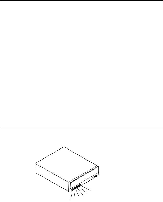
Locating the connectors on the front of your computer
The following illustrations show the location of the connectors on the front of the small desktop computers.
4931
|
|
|
|
|
|
|
|
|
|
|
|
|
|
|
|
|
|
|
|
|
|
|
|
|
|
|
|
|
|
|
|
|
|
|
|
|
|
|
|
|
|
|
|
|
|
|
|
|
|
|
|
|
|
|
|
|
|
|
|
|
|
|
|
|
|
|
|
|
|
|
|
|
|
|
|
|
|
1IEEE 1394 connector (some models) |
|
4S/PDIF connector |
||||||||||
2Front USB connector |
|
5Microphone connector |
||||||||||
3Front USB connector |
|
6Headphone connector |
||||||||||
© Copyright IBM Corp. 2000 |
19 |
1Front USB connector 2Front USB connector
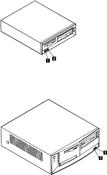
The following illustration shows the location of the connectors on the front of the desktop computer.
1Front USB connector 2Front USB connector
20 Hardware Maintenance Manual
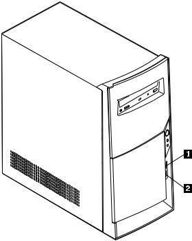
The following illustration shows the location of the connectors on the front of the microtower computer.
1Front USB connector 2Front USB connector
Chapter 4. Installing Options 21
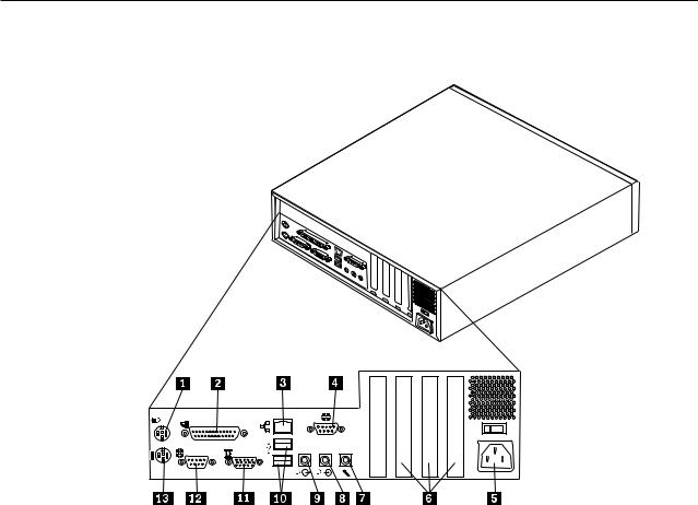
Locating the connectors on the rear of your computer
The following illustration shows the location of the connectors on the rear of the small desktop model computer.
1Mouse connector 2Parallel connector 3Ethernet connector 4Serial connector 5Power connector 6PCI slots 7Microphone connector
8 Audio line in connector 9 Audio line out connector 10USB connectors 11Monitor connector 12Serial connector 13Keyboard connector
Note: The connectors on the rear of the computer have color-coded icons to help you to determine where to connect the cables on your computer.
22 Hardware Maintenance Manual
Loading...