


PT26 D
Table of contents
 Loading...
Oper ator ′ s manual
PT26 D
Please r ead the operator’s manual carefully and make sure you
understand the instructions bef
ore using the machine.
EEEEnnnngggglllliiiisssshh
hh

Contents
Introduction ................................................ 3
Congratulations ............................................
Driving and Transport on Public Roads .......3
Towing ..........................................................3
Use ...............................................................3
Proper Service .............................................4
Serial Number ..............................................4
Symbols and Decals .................................. 5
Safety Instructions .....................................7
General Use .................................................7
Driving on slopes .......................................... 9
Children ........................................................10
Maintenance .................................................10
Transport ......................................................13
Environment protection ................................ 13
User responsibility ........................................14
Presentation ............................................... 15
1-2. Speed control ........................................17
3. Parking brake ...........................................17
4. Control panel ............................................18
5-9. Seat ....................................................... 18
10. Steering wheel and steering wheel console 19
11. Differential Lock .....................................19
12. Adjusting the cutting height ....................19
13. Fuelling ................................................... 19
21-37. Controls on the control panel ............20
21. Control lever hydraulics .......................... 20
22. Switch for operation of cutting unit .........21
23. Switch for extra hydraulic function (hydraulic kit op-
tion) .............................................................. 21
24. Push button for horn (traffic kit option) ...21
25. Indicators (traffic kit option) ....................21
26. Starter switch .........................................22
27. Headlight ................................................22
28. Throttle control ....................................... 22
29. High speed .............................................22
30. Weight transfer .......................................23
31. Rotating warning light (traffic kit option) .23
32. Parking lights (traffic kit option) ..............23
33. Spare ...................................................... 23
34-35.Power outlet .......................................23
36. Chronometer .......................................... 24
40-51. Warning lamps ..................................24
49. Lever for steering wheel console angle .. 24
Adjusting the steering wheel setting ............. 24
Rops .............................................................25
Cooling system ............................................. 26
Cutting unit ...................................................27
Accessories ..................................................28
Towing ..........................................................28
Driving ......................................................... 29
Mowing Tips ................................................29
Before Starting ............................................. 30
Starting the engine .......................................31
Driving the machine .....................................33
Braking ......................................................... 34
Cutting the engine ........................................34
Bleeding in the event of fuel stoppage. ........34
Engine stop .................................................. 34
Maintenance ............................................... 35
Maintenance Schedule ................................. 35
Cleaning ....................................................... 37
Removing the machine’s covers .................. 38
3
Checking radiatorgrilles ............................... 38
Cleaning the radiator's heat exchanger ....... 38
Adjusting the pump and generator drive belts 38
Replacing the pump and generator drive belts 39
Checking and adjusting the throttle control ..39
Checking the exhaust system ...................... 39
Adjusting the parking brake ......................... 39
Servicing the air filter ................................... 40
Cleaning the cyclone filter ............................40
Replacing the air filter .................................. 40
Bleeding the fuel system ..............................41
Servicing the fuel filter .................................. 41
Checking the Tyre Pressures ....................... 41
Servicing the battery .................................... 42
Fuses ........................................................... 42
Checking the Safety System ........................43
Replacing the bulb in the headlight ..............44
Light setting .................................................. 45
The Cutting Unit Components ...................... 45
Attaching and removing the cutting unit .......45
Side shifting the cutting unit ......................... 45
Setting the cutting height and tilt angle ........ 47
The Cutting Unit’s Service Position .............. 48
Cutting Unit Model ....................................... 49
Checking the Blades .................................... 50
Replacing the power take-off belts ............... 50
Adjusting the power take-off belts ................51
Replacing the cutting unit belt ......................51
Removal of BioClip Plug .............................. 52
Lubrication ................................................. 53
Lubrication Schedule ................................... 53
General ........................................................ 53
Lubricating the cables .................................. 53
Accessories .................................................. 54
Lubricating in Accordance with the Lubrication
Schedule ...................................................... 54
Trouble Shooting Guide ............................ 61
Storage ........................................................ 65
Winter Storage ............................................. 65
Service ......................................................... 66
Electrical system ........................................ 67
Hydraulic System .......................................68
Fuel system ................................................ 70
Technical Data ............................................ 71
Design standards .......................................75
1

2

Introduction
Chapter 1: Introduction
Congratulations
Thank you for purchasing a Husqvarna PT 26D. Husqvarna PTs have been designed according to a unique
concept with a front mounted cutting unit and Husqvarna's unique rear wheel steering. The machine is built to giv e
maximum efficiency even in small and difficult areas. Collected controls and a hydrostatic transmission controlled
by pedals also contribute to the machine’s performance.
This Operator’s Manual is a valuable document. Following the instructions (use, service, maintenance, etc.) can
considerably increase the service life of your machine and even increase its resale value.
When you sell your machine, make sure to give the operator’s manual to the new owner.
A service journal is available for the machine. Ensure that service and repair work is documented. A well-kept
service journal reduces service costs for the season-based maintenance and affects the machine’s resale value.
Take the service journal along when the machine is taken to the workshop for service.
Driving and Transport on Public Roads
Check applicable road traffic regulations before driving and transport on public roads. You should always use
approved load retainers during transport and ensure that the machine is well secured.
Towing
The PT 26D is equipped with hydrostatic transmission and a bypass valve must be used when towing.
Use
This machine is designed to mow grass on ordinary lawns and other open and level ground surfaces without
obstacles such as stones, stumps and the like. All other types of use are incorrect. The man ufacturer’s instructions
with regard to driving, maintenance and repair must be followed precisely, even when the machine is equipped with
special accessories supplied by the manufacturer for which operating instructions accompany the delivery.
This machine should be operated, serviced and repaired only by persons who are familiar with its particular
characteristics and who are acquainted with the relevant safety instructions.
Accident prevention regulations, other general safety regulations, occupational safety rules, and traffic regulations
must be observed.
Unauthorised modifications to the design of the machine may absolve the manufacturer from liability for any
resulting personal injury or property damage.
3

Introduction
Proper Service
Husqvarna’s products are sold all over the world and only by specialised retail traders offering complete service.
This ensures that you as a customer receive only the best support and service. Before the product is delivered, the
machine has, for example, been inspected and adjusted by your dealer, see the certificate in the Service Journal.
When you need spare parts or support concerning service, warranty issues, etc., please consult the following
professional:
This operator’s manual belongs to the
machine bearing serial number:
Engine Transmission
Serial Number
The serial number can be found on the printed plate attached on the right-hand side under the seat. The plate
includes the following information:
• The machine’s type designation.
• Weight.
• The manufacturer's type number.
• The machine’s serial number.
• Manufacturer.
Please state the type designation and serial number when ordering spare parts.
The engine’s serial number is on the engine block above the injection pump.
Please state this when ordering spare parts.
The hydraulic pump and h ydraulic motors are equipped with rating plates that indicate type designation and serial or
manufacture numbers.
Please state these when ordering spare parts.
4
Symbols and Decals
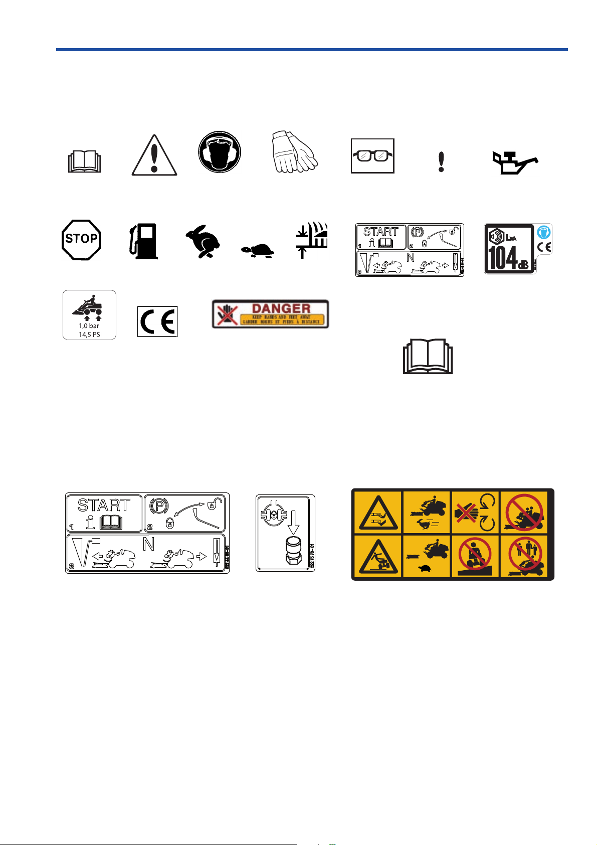
Chapter 2: Symbols and Decals
These symbols are found on the machine and in the operator’ s man ual. Symbols for control units and warning lamps
are displayed in chapter “Presentation”, see page 42 and following pages.
Study them carefully so you understand their significance.
Read the
operator's manual
Engine off
Tyre
pressure
Read the
Operator's manual
Warning
Fuel Fast
CE conformity
marking
Parking brake
Use hearing
protection
Slow
Use protective
gloves
Cutting
Danger. Keep your hands and
feet away
Use protective
glasses
Poisonous
Hazardous to
health
Starting instructions:
Activate the parking brake
Read the operator’s manual
Hydrostat pedals in neutral
position
Do not insert
your hands
or feet under
the cover
when the
engine is
running
Warning!
Rotating
blades
Only for
attached
cutting unit
Oil level
Noise emission to
surroundings in
accordance with the
directive of the
European Community.
The machine’s
emission is indicated in
the TECHNICAL DATA
chapter and on the
decal.
Never carry
passengers
on the
machine
or on its tools.
10 - 61 93 445
Pedal forwards
Pedal backwards
Differential lock
Warning!
Risk of the
machine
overturning
Drive very
slowly
without the
cutting unit
Never
drive
directly
across a
slope
Never use the
machine if
there are
people,
especially
children, or
pets, in the
immediate
vicinity.
5

Symbols and Decals
WARNING:
Xxxxxx x xxxx xxxxx xxxxx xxxxx Xxxxxxxxxxx xxx
xxxxxx. Xxxx xxxxxxx xxx xx xxxx
Used in this publication to notify the reader of a risk of serious personal injur
neglect to follow instructions given in the manual.
y , particularly if the reader should
IMPORTANT INFORMATION:
Xxx xxx xxxx xxxxxxxxx xxx xxxxx xxx xxxx xx
xxxxx xx xxxxx. Xxx xxxxxxxx xx x x xxxxxxx xx
xxxx xxxx.
Used in this publication to notify the reader of a risk of material damage , particularly if the reader should neglect to
follow instructions given in the manual. Used also when there is a potential for misuse or misassembly.
Avoid hosing the decals with high pressure washers. Replace damaged decals before the machine is used.
6
Read the operator’s manual before starting the machine
Clear the area of objects before mowing
Never take passengers
Safety Instructions
Chapter 3: Safety Instructions
These instructions are for your safety. Read them
carefully.
General Use
• Read all instructions in this operator’s manual and
on the machine before starting it. Ensure you
understand them and then observe them.
• Learn how to use the machine and its controls
safely and learn how to stop quickly. Also learn to
recognise the safety decals.
• If you get into a situation where you feel unsure
about how to progress, stop and seek expert
advice. Contact your Husqvarna retailer, service
agent or an experienced user. Avoid all usage that
you consider to be beyond your capability.
• Only allow the machine to be used by adults who
are familiar with its use.
• Make sure nobody else is in the vicinity of the
machine when you start the engine, engage the
drive, or run the machine.
• Clear the area of objects such as stones, toys,
steel wire, etc. that may become caught in the
blades and thrown out.
• Beware of the rear ejector and do not point it at any
one.
• Stop the engine and prevent it from starting before
you clean the cutting unit.
• Remember that the driver is responsible for
dangers or accidents.
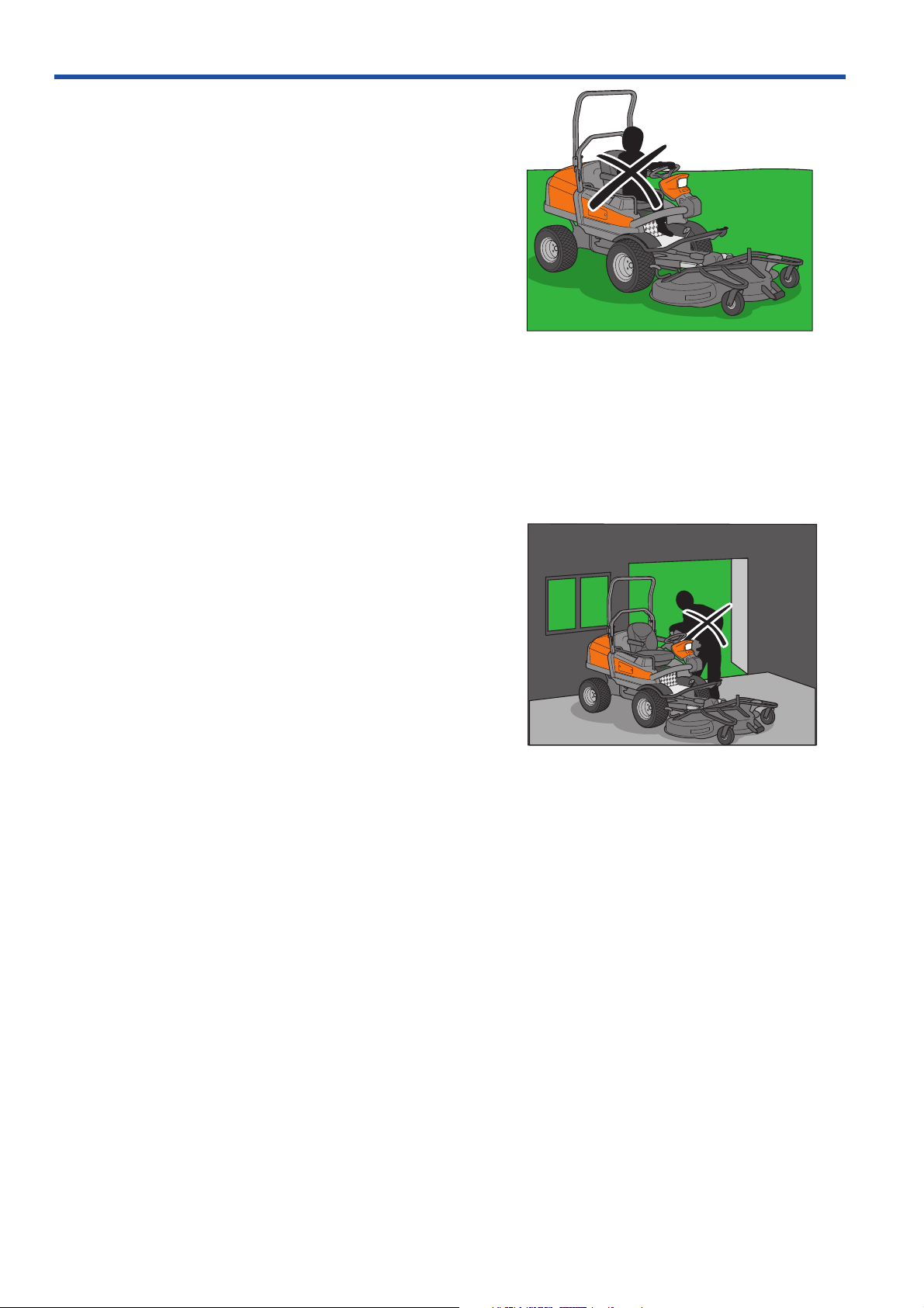
• Never carry passengers. The machine is only
intended to be used by one person.
• Always look down and behind before and during
reversing manoeuvres. Keep watch for both large
and small obstacles.
• Slow down before turning.
7
Shut down the blades
Keep children away from the work area
Personal protective equipment
Safety Instructions
• Shut down the blades when not mowing. The
lades must only be running when the cutting unit
b
is lowered and active when used for mowing.
• Be careful when rounding fixed objects, so that the
blades do not hit them. Nev er run the machine ov er
foreign objects.
• Never drive close to objects or other machines.
Remember that “Brake pedal reflex” from driving a
car has the opposite effect if you press on the
forward pedal.
WARNING:
Engine exhaust, some of its constituents and certain
vehicle components contain or emit chemicals
considered to cause cancer, birth defects or other
reproductive impairment. The engine emits carbon
monoxide, which is a colourless, poisonous gas. Do
not use the machine in enclosed spaces.
• Only use the machine in daylight or in other well-lit
conditions. Keep the machine at a safe distance
from holes or other irregularities in the ground. P ay
attention to other possible risks.
• Never use the machine if you are tired, if you hav e
consumed alcohol, or if you are taking other drugs
or medication that can affect your vision,
judgement, or co-ordination.
• Beware of traffic when working near or crossing a
road.
• Never leave the machine unsupervised with the
motor running. Always stop the blades, apply the
parking brake, stop the engine and remove the
keys before leaving the machine.
• Never allo w children or other persons not trained in
the use of the machine to use or service it. Local
laws may regulate the age of the user.
WARNING:
You must use approved personal protective
equipment whenever you use the machine. Personal
protective equipment cannot eliminate the risk of
injury but it will reduce the degree of injury if an
accident does happen. Ask your dealer for help in
choosing the right equipment.
• Use hearing protection to minimise the risk of
hearing impairment.
• Wear approved protective goggles or a full visor
when driving.
8
Mow upwards and downwards on slopes, not sideways.
Be extra cautious when driving on slopes
• Never use the machine when barefoot. Always
ear protective shoes or protective boots,
w
preferably with steel toes.
• Make sure that you have first aid equipment close
at hand when using the machine.
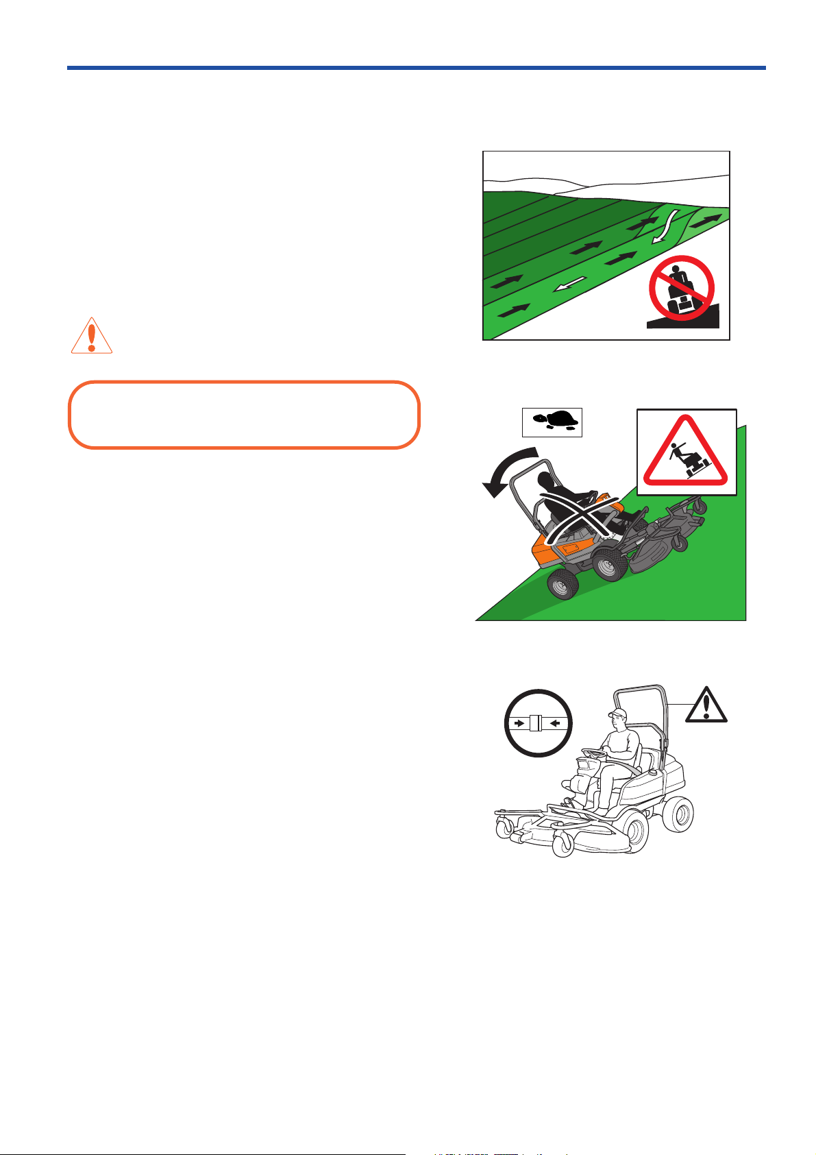
Driving on slopes
Driving on slopes is one of the operations where the
risk of the driver losing control of the machine or of it
overturning is the greatest; this can result in serious
injury or death. All slopes demand extra care. If you
cannot reverse up a slope or if you feel unsure, do not
mow it.
WARNING:
Do not drive down slopes with the unit raised.
Control can be reduced due to the changed centre of
gravity.
Safety Instructions
Do as follows
• Remove obstacles such as stones, tree branches, etc.
• Mow up and down, not side-to-side.
• The differential lock should also be used on slopes.
• Never drive the machine on terrain that slopes
more than 10°.
• Avoid starting or stopping on a slope. If the tyres
start to slip, stop the blades and drive slowly down
the slope.
• Always drive evenly and slowly on slopes.
• Always use rops and safety belt when driving on slopes
• Make no sudden changes in speed or direction.
• Avoid unnecessary turns on slopes, and if it proves
necessary , turn slowly and gradually do wnw ard, if possib le.
• Watch out for and avoid driving over furrows, holes, and
bumps. It is easier for the machine to overturn on uneven
ground. Tall grass can hide obstacles.
• Drive slowly. Do not turn the wheel sharply.
• Be extra cautious with any additional equipment, which can
alter the machine’s stability.
• Do not mow near verges, ditches, or banks. The machine
can suddenly overturn if one wheel comes over the edge of
a steep slope or a ditch, or if an edge gives way.
• Do not mow wet grass. It is slippery, and tyres can lose
their grip so that the machine skids.
• Try not to stabilise the machine by putting a foot on the
ground.
• When cleaning under the machine, it may never be driven
near verges or ditches.
9
Never fill the fuel tank indoors
Safety Instructions
Children
• Serious accidents may occur if you fail to be on
guard for children in the vicinity of the machine.
Children are often attracted to the machine and
mowing. Never assume that children will stay put
where you last saw them.
• Keep children away from the mowing area and
under close supervision by another adult.
• Keep an eye out and shut off the machine if
children enter the work area.
• Before and during a reversing manoeuvre, look
backward and downward for small children.
• Never allow a child to ride with you. They can fall
off and seriously injure themselves or be in the way
for safe manoeuvring of the machine.
• Never allow children to operate the machine.
• Be particularly careful near corners, bushes, trees
or other objects that block your view.
Never allow children to operate the machine
Maintenance
• Stop the engine. Remove the ignition key before
making any adjustments or carrying out
maintenance.
• Never fill the fuel tank indoors.
• Only store fuel in clean containers approved f or the
purpose.
• Never remove the fuel cap or fill the fuel tank with
fuel while the engine is running.
• Allow the engine to cool before refuelling. Do not
smoke.
• Handle oil, oil filters, fuel and the battery carefully,
of environmental considerations. Observe
applicable recycling regulations.
• Do not allow compressed air to come into contact
with skin. If compressed air penetrates the skin,
seek medical advice immediately.
• Seek medical advice immediately if skin comes into
contact with fuel, which that is under high pressure.
• The combustible material in some of the engine’s
components (e.g. certain seals) can be very
dangerous if ignited. Never allow burnt material to
come into contact with skin or eyes.
• Do not remove the filler cap or any other
component on the cooling system when the engine
is hot or under pressure, as hazardous hot coolant
can spray out.
10
Tank with level window
Risk of sparking
WARNING:
The engine, exhaust system, cooling system and
hydraulic system components become extremely hot
during operation. Risk of burn injuries if touched.
Wear protective gloves
• If leaks arise in the fuel system, the engine must
not be star
• Store the machine and fuel in such a way that
there is no risk of leaking fuel or fuel vapour
leading to damages.
• Check the fuel level before each use and leave
space for the fuel to expand, because the heat
from the engine and the sun may otherwise cause
the fuel to expand and overflow.
ted until the problem has been resolved.
Safety Instructions
• Avoid overfilling. In the event of spilling fuel on the
machine, wipe it up before starting the engine. If y ou
spill petrol on your clothing, change your clothing.
• Material that has been contaminated by fuel must be
moved to a fire proof and environmentally safe place.
• Allow the machine to cool before taking any
actions in the engine room.
WARNING:
The battery contains lead and lead compounds,
chemicals that are considered to cause cancer, birth
defects, and other reproductive system damage.
Wash you hands after touching the battery. Use
protective goggles when working with the battery.
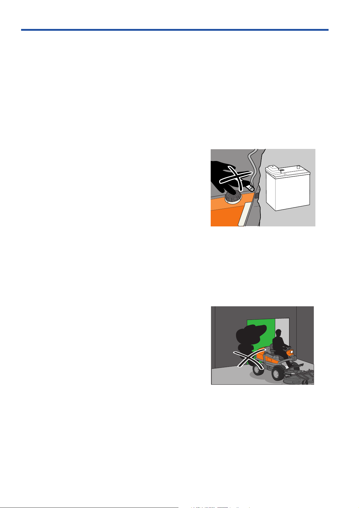
• Sparking can occur when working with the battery
and the thick cables in the starter motor circuit.
This can cause the battery to explode, fire or eye
injuries.
Sparking in the circuit can not occur once the
battery's power connection cable (usually the black
negative cable) has been disconnected.
Avoid sparking and its consequences by:
Wearing protective glasses.
Make sure that the fuel cap is fitted and that no
IMPORTANT INFORMATION:
11
Safety Instructions
Do not smoke when carrying out maintenance
Never drive the machine in an enclosed space
flammable liquids are stored in an open container.
Do not w
ork on the starter motor circuit in the vicinity of
spilt fuel.
Disconnect the battery's power connection cable (usually
the black negative cab le) first and connect it last.
Exercise care with tools so that short circuiting does
not occur.
Do not short circuit across the starter relay's
connections to run the starter motor.
• Be especially careful when handling battery acid.
Acid on the skin can cause serious corrosive
injuries. In the event of spillage on the skin wash
immediately with water.
• Acid in the eyes can cause blindness, contact a
doctor immediately.
• Be careful when servicing the battery. Explosive
gases form in the battery. Never perform
maintenance on the battery while smoking or in the
vicinity of open flames or sparks. This can cause
the battery to explode and cause serious injuries.
• Make sure all nuts and bolts are tightened correctly
and that the equipment is in good condition.
• Do not modify safety equipment. Check regularly to be
sure it works properly. The machine must not be driven
if protective plates, protective covers, safety switches or
other protective devices are not fitted or are defective.
• Do not change the settings of governors and avoid
running the engine with overly high engine speeds. If
you run too fast, you risk damaging the machine
components.
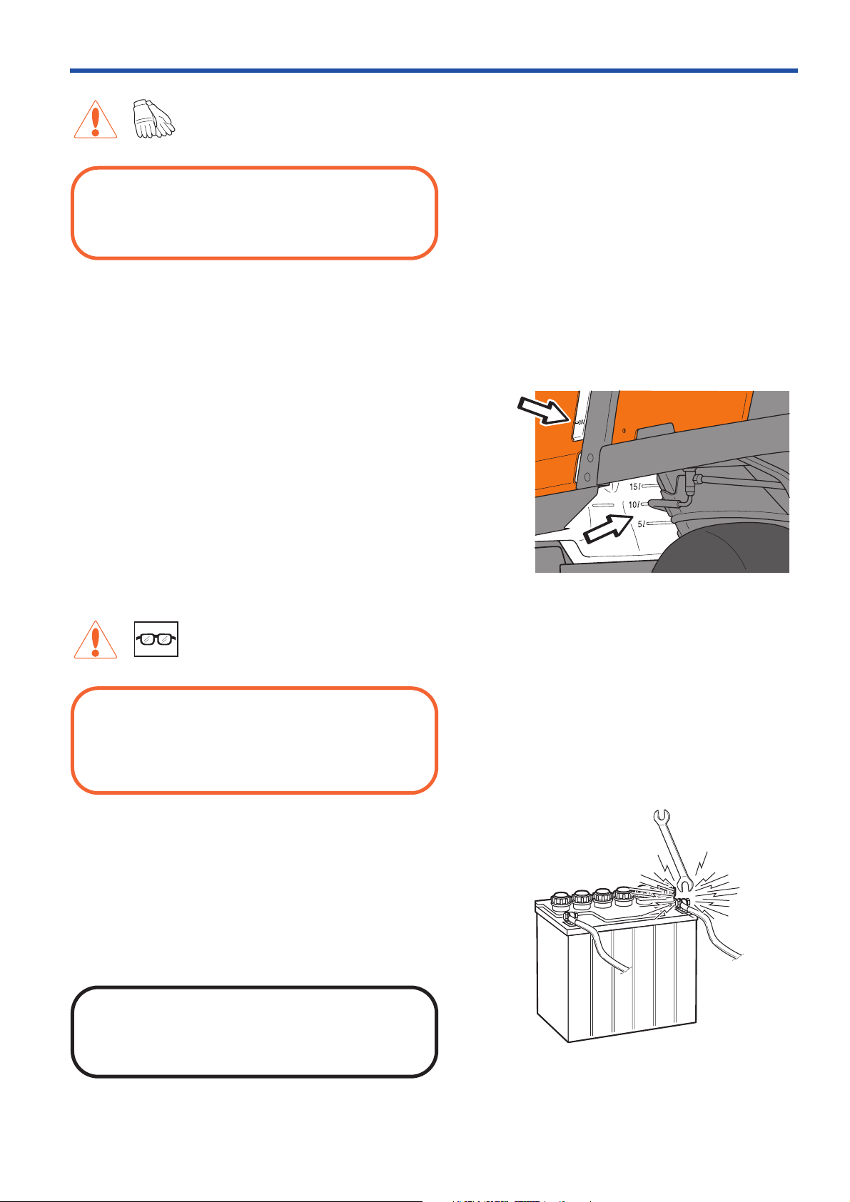
• Never use the machine indoors or in spaces lacking
proper ventilation. Exhaust fumes contain carbon
monoxide, an odourless, poisonous and highly
dangerous gas.
• Stop and inspect the equipment if you run over or into
anything. If necessary, make repairs before starting.
• Never make adjustments with the engine running.
• The machine is tested and approved only with the
equipment originally provided or recommended by the
manufacturer.
• The blades are sharp and can cause cuts and gashes.
Wrap the blades or wear protective gloves when
handling them.
• Check the parking brake’ s functionality regularly. Adjust
and maintain as required.
• The mulching unit should only be used where better
quality mowing is required and in known areas.
12
• Reduce the risk of fire by removing grass, lea ves
Clean the machine regularly
Front securing eyelets
and other debr
machine. Allow the machine to cool before
putting it in storage.
• Do not turn over the engine by hand without
preventing the engine from starting, which can be
done in different ways:
a. Remove the glow plug, no compression the
engine can therefore be easily turned over.
b. Loosen a pressure pipe connection on each jet
pipe a 1/2 turn.
c. Secure the injection pump stop arm in position for
zero supply.
is that may have fastened in the
Safety Instructions
Transport
IMPORTANT INFORMATION:
The parking brake is not sufficient to lock the
machine during transport. Ensure you secure the
machine firmly to the transporting vehicle.
The machine is heavy and can cause serious
crushing injuries. Be extra cautious when it is loaded
on or unloaded from a vehicle or trailer.
• Use an approved trailer to transport the machine.
Activate the parking brake and secure the
machine using approved fasteners, such as
straps, chains or ropes when transporting.
• Check and comply with laws and regulations
when driving on public roads, a traffic kit is
available as an option. This can be retrofitted on
PT 26D.
Environment protection
Take care of the environment, there are numerous
environmental risks especially when performing
maintenance on the machine. This particularly
applies when dealing with engine oil, hydraulic oil,
fuel, oil filters, hydraulic filters and fuel filters. You
must be attentive to ensure spillage does not occur
when you open a system that contains oil or fuel.
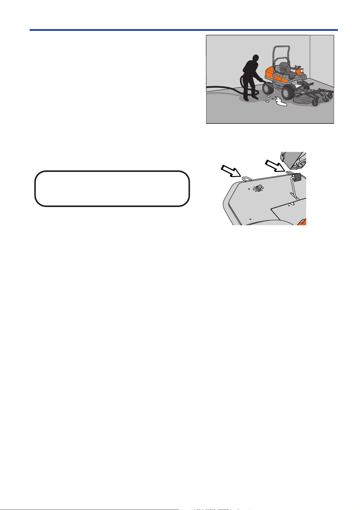
• Always wipe up spillage. When using cloths,
sawdust or oil absorbents, these should be
treated as environmental hazardous waste.
Follow local regulations.
• Choose an area, preferably with a concrete floor,
when you handle or store oils and fuel so that
you can clear up any spillage without it
penetrating into the ground.
• Avoid spillage, use a funnel and fill carefully.
• When draining, ensure that a suitably sized
container is placed correctly. Remember that the
oil does not always run straight down.
• Transfer the waste oil into a sealed container and
13

Safety Instructions
hand in for destruction. Remember to follow local
regulations
workshops or petrol stations that handle waste oil.
• Replaced oil and fuel filters are environmental
hazardous waste, handle them as waste oil.
• Do not spill fuel when refuelling. One litre of diesel
fuel can, according to the Swedish Rescue
Services Agency , destroy up to one million litres of
drinking water. Spilt fuel is a fire risk.
• Wash your hands thoroughly when the job is done.
• Coolant is poisonous and sweet. Ensure that
animals do not come into contact with open
containers or pools of fluid.
• Bear in mind the risk of grass fire when working in
dry vegetation. Never operate a machine with a
modified or damaged muffler, as sparks from the
exhaust fumes can set dry grass on fire.
. Gener ally you can deposit waste oil at
User responsibility
• Study and follow the safety instructions, see
“Safety Instructions” on page 7.
• Follow the maintenance schedule for care, see
“Maintenance Schedule” on page 71, lubrication
chart, see “Lubrication Schedule” on page 111 and
the instructions for operating the machine, see
“Presentation” on page 29 and “Driving” on
page 57.
• Follow the maintenance instructions, see
“Maintenance” on page 71, lubrication, see
“Lubrication” on page 111 and storage, see
“Storage” on page 133.
14
PT 26D
Speed control
Differential lock pedal
Presentation
Chapter 4: Presentation
Congratulations on your choice of an exceptionally
high quality product. This operator's manual describes
Husqvarna PT 26D.
It is fitted with a Perkins 3 cylinder diesel engine
developing 26 horse power.
PT 26D is equipped with hydraulic steering and
attachment lift. They are supplied with pressure from a
pump on the engine.
The machine is all wheel drive in low speed mode.
The power transmission from the engine is hydrostatic.
It is supplied with pressure by a pump under the
driver’s seat. A shaft with two flexible couplings powers
the pump. Flow and direction are regulated with the
pedals, so that forward and reversing speeds are
variably controlled. One pedal to drive f orwards (1) and
one pedal to reverse (2). The pump drives four
hydraulic motors in parallel, one for each wheel.
The power transmission is also used as service brake.
There are low and high speeds for driving. High or low
speed is selected using a switch.
The machine is equipped with an electro-hydraulic
differential lock, which is controlled by a pedal. The
differential lock only works longitudinally, which means
that you can turn the machine with the differential lock
activated.
The differential lock does not work in high speed.
Rear light, horn, direction indicators and rotating
warning lights are optional equipment (traffic kit).
The cutting unit takes power from the engine by means
of an electromagnetic clutch, two V-belts, apower takeoff shaft, a propeller shaft and a bevel gear.
15
Presentation
Placement of controls
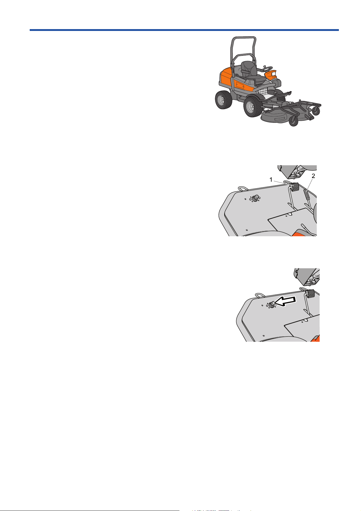
1. Speed control for driving forwards page 17
2. Speed control for reversing page 17
3. Parking brake page 17
4. Control panel page 16
5. Knob for the backrest rake page 18
6. Catch for seat folding page 18
7. Knob for the lumbar support page 18
8. Lever for lateral seat adjustment page 18
9. Knob for seat suspension page 18
10. Steering wheel console page 17
11. Pedal for differential lock page 19
12. Cranks for setting cutting height page 19
13. Fuel tank cover page 19
16
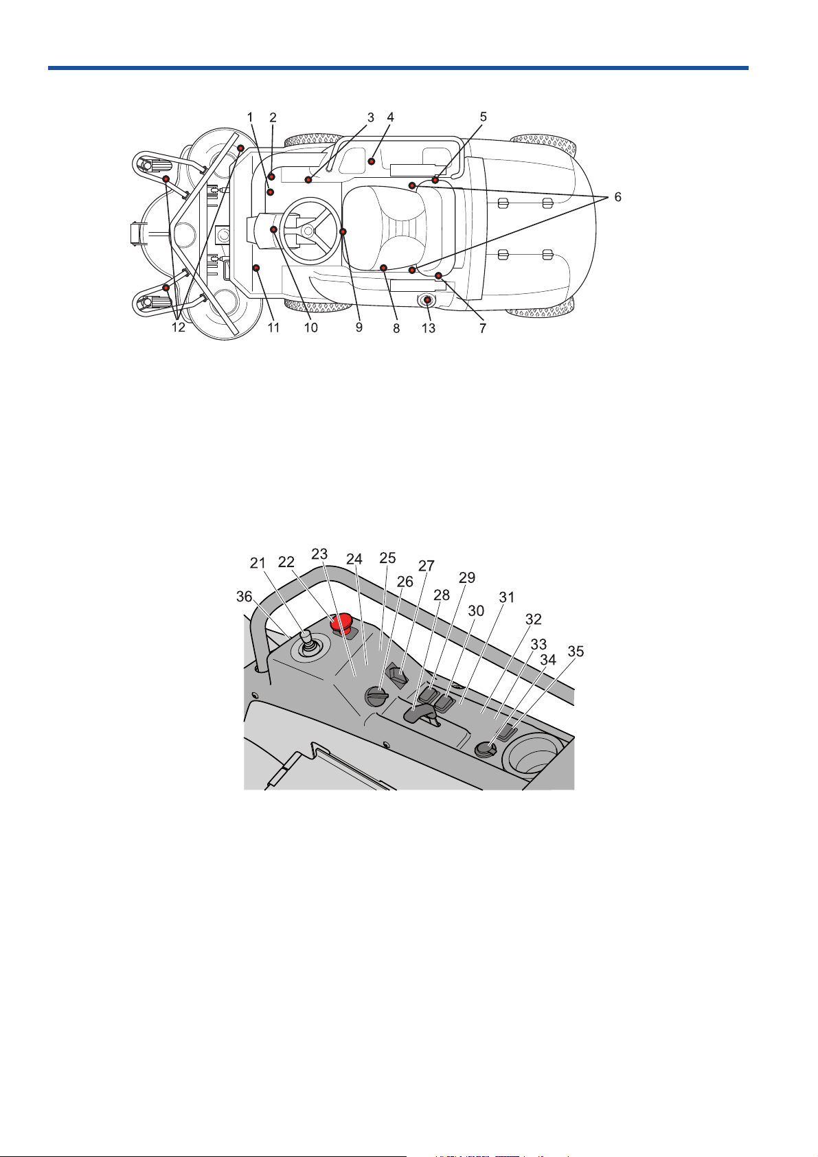
Control panel
21. Control lever hydraulics page 20
22. Switch for operating the cutting unit page 21
23. Switch for 2nd hydraulic function (option) page 21
24. Horn switch (option) page 21
25. Turn signal lights switch (option) page 21
26. Starter switch page 22
27. Switch for the lights page 22
28. Throttle control page 22
29. Switch for high and low speed page 22
-
30. Switch for weight transfer page 23
31. Rotating warning light (option) page 23
32. Parking lights (option) page 23
33. Spare
34. Power outlet page 23
35. Mains switch power outlet page 23
36. Chronometer page 24
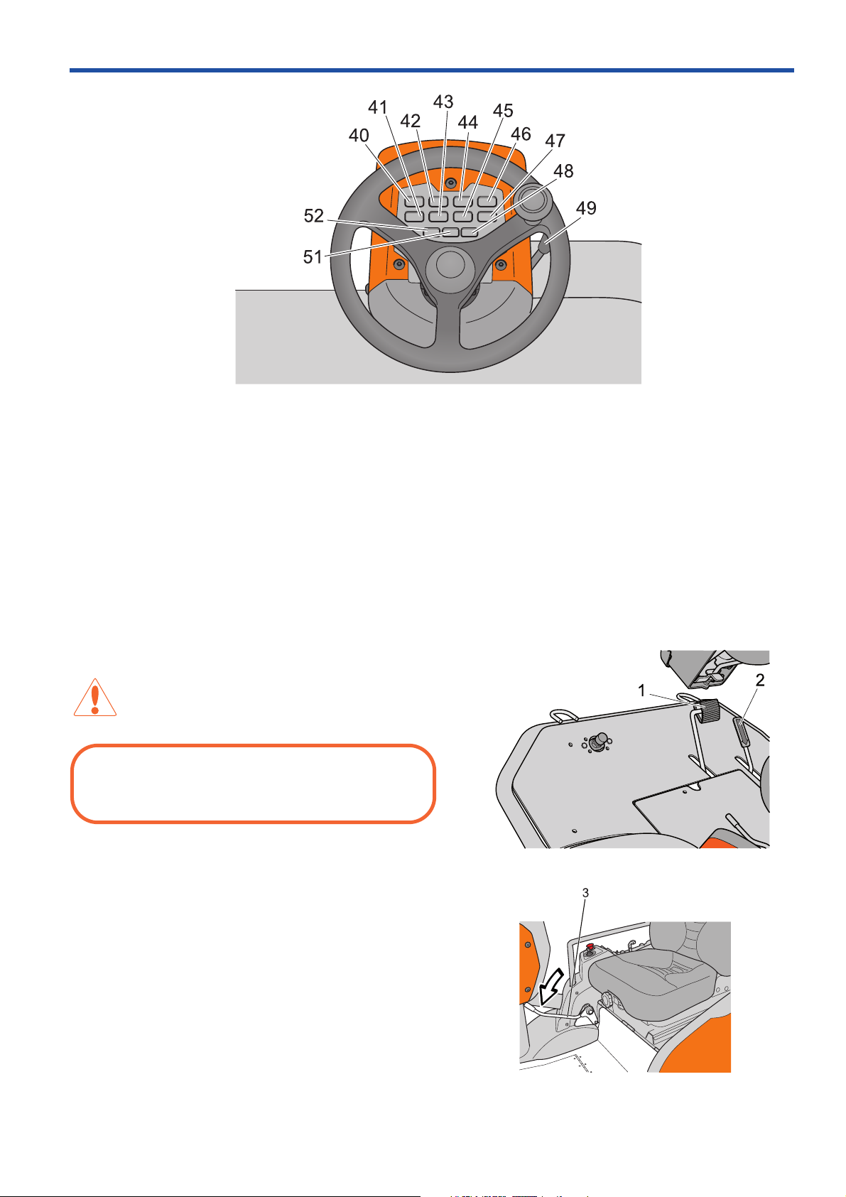
Steering wheel console
Speed control
Parking brake
Presentation
40. Warning lamp Battery charging page 24
41. Warning lamp Differential lock page 24
42. Warning lamp Coolant temperature page 24
43. Warning lamp Glow plug heating page 24
44. Warning lamp Engine oil pressure page 24
45. Warning lamp Cutting unit operation page 24
46. Warning lamp Parking brake page 24
1-2. Speed control
The speed of the machine is variably controlled using
two pedals. Pedal (1) is used to travel forwards and
pedal (2) to reverse.
WARNING:
Make sure that no branches can interfere with the
pedals when mowing under bushes.
47. Warning lamp High speed page 24
48. Warning lamp Right-hand indicator page 24
49. Lever for tilting the steering wheel console page 24
50. Warning lamp Full beam page 24
51. Warning lamp Left-hand indicator page 24
3. Parking brake
Apply the parking brake by moving the handle forward.
Release the parking brake by moving the handle back.
17
Presentation
Seat lock
6
Lateral adjustment and adjusting suspension
4. Control panel
There are controls and switches on the control panel
on the right-hand side of the driver that are used when
operating the machine. The lower section of the panel
is equipped with a cover over the machine’s fuses and
relays. See “21-37. Controls on the control panel” on
page 20.
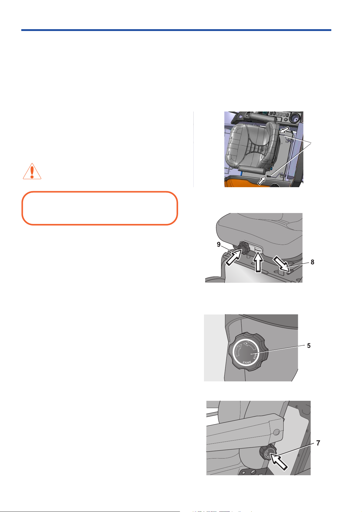
5-9. Seat
The seat has a hinged mounting on the front edge and
can be folded forwards.
To fold the seat forward, the steering wheel console
must be folded forwards and the lock (6) for the seat
operated.
WARNING:
Do not adjust the seat whilst driving. Risk of unsafe
operation.
The seat can also be adjusted lengthways:
• When making adjustments, the lever (8) under the
left-hand side of the seat is moved to the left, after
which the seat can be moved backwards or
forwards to the desired position.
• The seat’s suspension can be adjusted by turning
the knob (9) under the front edge of the seat. A
scale indicates the setting.
There are two knobs on the sides of the backrest:
• Backrest tilt is adjusted using the knob (5) on the
right-hand side of the seat.
• Lumbar support is adjusted using a knob (7) on the
left-hand side of the backrest.
18
Knob for the lumbar support
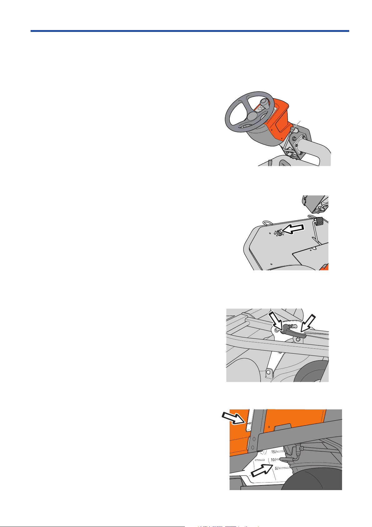
10. Steering wheel and steering wheel console
Steering wheel and steering wheel console
Differential lock pedal
Front cutting height adjustment
Tank with level window
The position of the steering wheel can be adjusted
vertically. The mounting for the steering unit in the
steering column can be adjusted vertically.
Depress the lever (49) and fold the steering wheel
console to one side to facilitate entering the driver’s
seat. The steering wheel console can be adjusted
lengthways.
See “40-51. Warning lamps” on page 24.
The headlights are set using the knob in the position
closest to the driver. In the second position the range
of the lighting will decrease.
Presentation
49
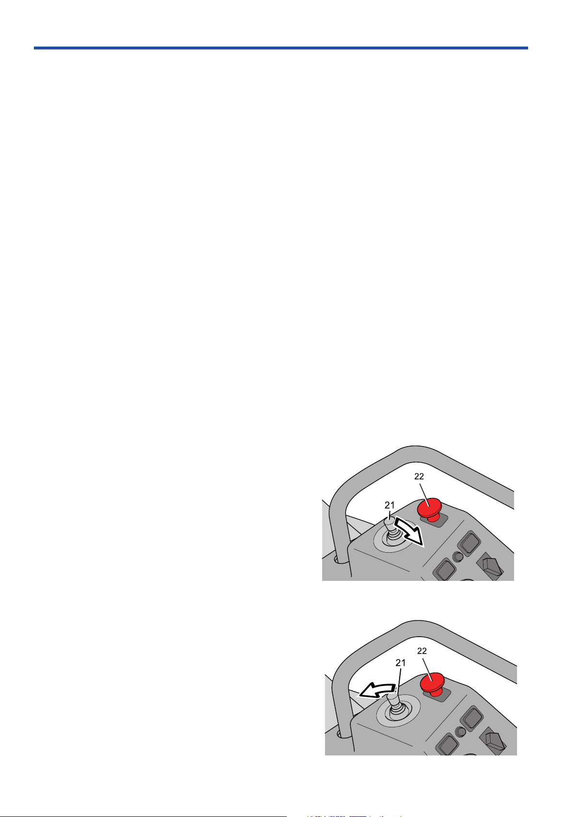
11. Differential Lock
The differential lock is electro-hydraulic. It is operated
by a pedal controlled switch. The differential lock only
works longitudinally, it ensures operation on at least
one front wheel and one rear wheel. This means that
you can turn the machine with engaged differential
lock without causing any interruptions in the power
transmission or damage to the lawn.
As the differential lock is not mechanical, it can be
engaged or disengaged without limitation, even when the
machine freewheels or in the ev ent of wheel spin. When
the pedal is released, the differential lock disengages
without the driver having to carry out any other
operations. The differential lock only works at low speed
and is active both up and down slopes.
12
.
Adjusting the cutting height
The cutting height adjustment allows the cutting height
to be adjusted in seven different positions 25.4 mm 127 mm (1” - 5”).
In order to obtain an even cutting height, it is important
that the settings are in the same positions and the air
pressure is the same in the front wheels, 100 kPa /
1.0 bar / 14.5 PSI and in the cutting unit’s pivot wheels
150 kPa / 1.5 bar / 21,7 PSI
When the adjustments have been made, the cr anks
should be released using the button in the crank and set
to a position that does not catch on any bushes or similar .
13. Fuelling
The fuel level in the tank is indicated in the sight glass.
Do not fill the tank completely , lea ve an area of at least 2.5 cm (1").
Fill the fuel tank with diesel. Do not use petrol under
any circumstances.
Use fuel with a cetane rating of above 45. Max RME
mixture 5 % in mineral oil based fuels. Aviation kerosene
(JP5, JP8 and Jet-A) can be used if lubricant additives
are used, but the starting ability may be affected. JP4 is
not recommended. Unmixed RME can be used.
19
Presentation
Raising the cutting unit with the lifting lever
Mowing Position
Do not smoke when filling the tank with fuel.
Diesel is less flammab
point. This varies depending on the type of diesel but is normally higher than +50 °C (120 °F).
Observe fuel hygiene. The diesel engine’s fuel injection system is very sensitive and can be damaged by
contaminants, which may be so small that they cannot be seen with the naked eye. Only use clean containers
(closed + dust-free funnel). Wipe away any dust before remo ving the fuel tank filler cap . There is a filter to protect the
fuel injection system, however if it becomes blocked operational malfunctions may occur. Rectifying damage,
operational malfunctions, filter replacement caused by poor hygiene are not repairs that are covered under warranty
Remember the environmental risks. See “Environment protection” on page 26.
Wipe up any spillages. Material that has been contaminated by fuel must be moved to a safe place.
If you spill fuel on your clothes, change to prevent skin irritations.
Winter fuel and paraffin precipitation
Malfunctioning can occur when driving in extremely
cold conditions on account of paraffin precipitation,
which can occur if using standard fuel. To avoid this,
winter fuel, diesel with additives to prev ent precipitation,
is sold in relevant climates . In certain regions different
types of summer and winter fuels are sold, in other
regions. winter fuel is sold all year round. Ask you fuel
supplier and only use winter fuel below 0 °C (+32 °F).
le than petrol at normal temperatures, but becomes very flammable if heated to the flash
21-37. Controls on the control panel
The control panel is prepared for optional extr as, which
are sold as accessories for PT 26D. Therefore, some
of the following control units may not be included with
your machine.
21. Control lever hydraulics
The lifting lever is used to put the cutting unit in either
the transport or mowing position when hydraulic
pressure is available.
Lifting the cutting unit (transport position)
Stop the blades by pressing in the s witch for driving the
cutting unit (22).
Pull the lever backward to engage the transport position.
The unit is then raised.
The cutting unit can be raised slightly with the blades
in operation. This is to facilitate work when cutting in
extremely tall grass or on uneven surfaces. The
machine is, however, equipped with an automatic
blade stop function, which is activated when the cutting
unit reaches the transport position. If the automatic
blade stop is activated, the switch (22) must be
pressed in and pulled out to restart.
Lowering the unit (mowing position)
Move the lifting lever forwards to engage the cutting
position. The unit is then lowered. The lever does not
need to be held in position, allow it to spring back to
the zero position when the unit has been lowered.
The blades are started with the switch for driving the
cutting unit (22).
Weight transf er can be activated, which means the cutting
unit follows the ground contour and une v enness on the
lawn more precisely. See “W eight tr ansf er” page 23
20
Other functions (option)
Switch for operation of cutting unit
When the le
operated to the 2nd hydraulic function, the terminals
are under the foot plate hatch.
ver is moved laterally, the oil pressure is
22. Switch for operation of cutting unit
The cutting unit can only be started when the driver is sitting in
the seat.
• Pull out the switch to engage cutting unit operation.
• Press in the switch to disengage cutting unit
operation.
If the safety circuit trips cutting unit operation, the
switch must be pressed in and pulled out again.
The safety circuit trips and the cutting unit stops:
When the cutting unit is raised to the uppermost
position
When the driver leaves the seat. There is a brief delay to
prevent stoppages should the driver bounce in the seat
When high gear is engaged.
When the starter is activated.
Presentation
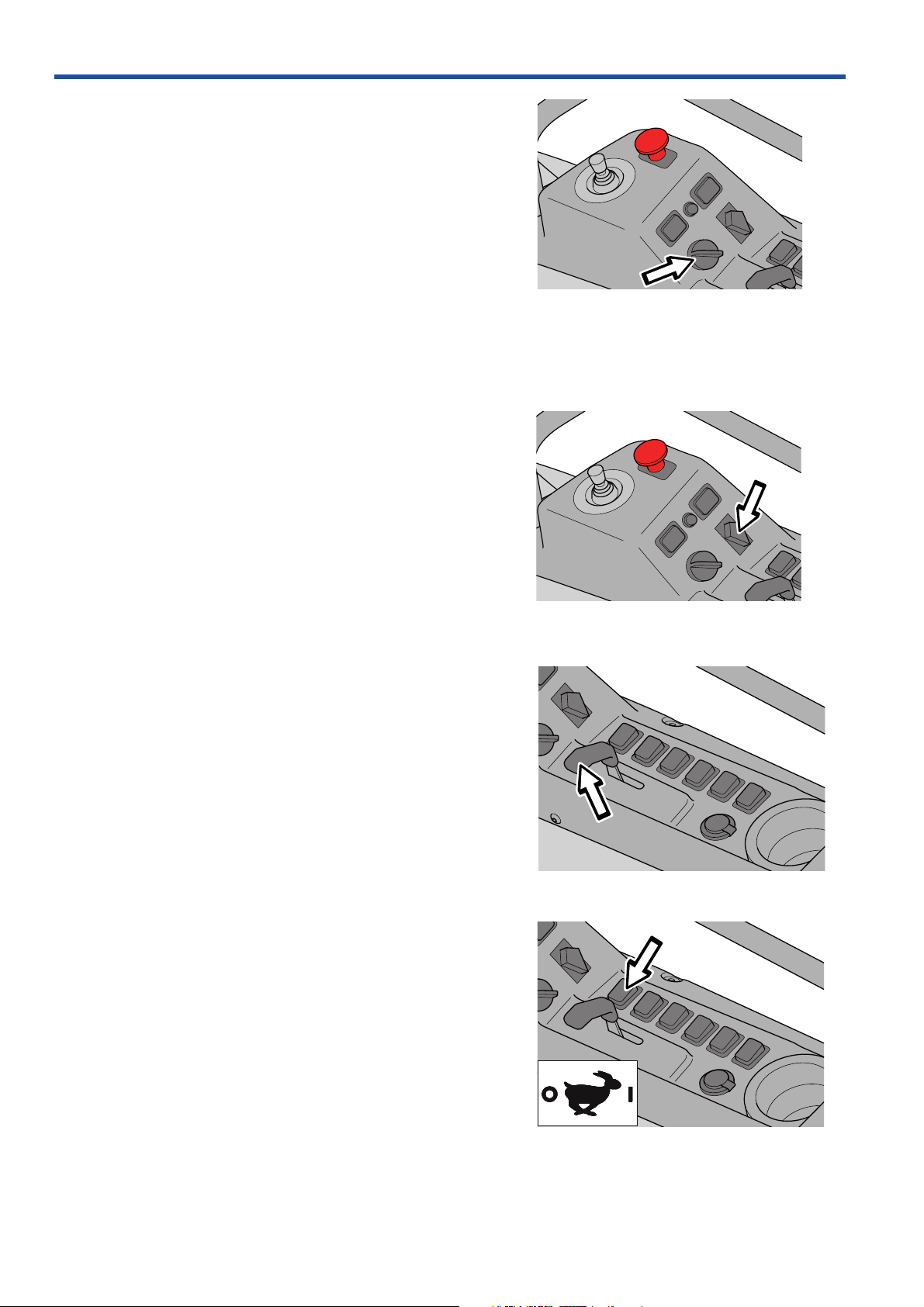
23. Switch for extra hydraulic function
(hydraulic kit option)
The switch is used, among others, when steering the
folding plough for individual control of the left or righthand plough-blades. Operate the plough blade using
the lever (21).
24. Push button for horn (traffic kit option)
Switch for extra 12 V outlet
Switch for horn
25. Indicators (traffic kit option)
Press for the left-hand or right-hand indicator. Blinkers
are switched off automatically after approximately
30 seconds or manually by pressing in the same
direction. A new 30 second period is activated if you
press after the blinkers have been switched off.
Pressing in the opposite direction while flashing,
activates the blinkers for the opposite side for
30 seconds.
Switch for indicators
21
Presentation
Throttle control
High speed
26. Starter switch
Three positions:
• OFF
All functions switched off. The engine is stopped. The
parking light can be switched on (traffic kit option).
•ON
Normal operating position.
• Start and Preheating
Keep the s witch in the glo w plug mode, when glow
plug heating is complete the starter is engaged.
During glow plug heating, light (43) on the indicator
panel comes on. Non-locking to position ON.
Turning again within 2 seconds gives starting
without glow plug heating.
27. Headlight
Three positions, clockwise in the following order:
Starter switch
• Off:
• Dipped beam
• Full beam
If the switch is moved to the Dipped beam position
automatic dipped beam mode, dipped beam is
switched on when the engine is running.
28. Throttle control
The accelerator is used to control the speed of the engine
and thereby also the rotation speed of the blades.
In order to increase or decrease the engine speed, the
control is moved forwards or backwards respectively.
29. High speed
Switch for headlight
Activated switch. This switch is used to select either
high or low speed.
The speed must drop to zero before the machine shifts
to low speed if high speed is actuated.
If the differential lock is actuated, the machine will not
shift to high speed until the pedal is released.
Front wheel drive is engaged in high speed mode.
All wheel drive is engaged in low speed mode.
The differential lock and cutting unit only work in low
speed mode.
22
30. W eight transfer
Weight transfer
Rotating warning light
Parking lights
Power outlet with switch
Weight transf er is activated using this switch, transfers
a proportion of the unit’s weight to the machine. This
causes greater ground pressure on the machine’ s front
wheels and lower ground pressure on the unit’s pivot
wheels.
It is recommended to use weight transfer when lawn
mowing and sweeping. When snow clearing or
changing tools, the function should be off so that the
lifting arms can be lowered.
This function works when the lower position is selected
with control lever (21).
31. Rotating warning light (traffic kit option)
Observe any local traffic laws when using the warning
light.
Presentation
32. Parking lights (traffic kit option)
Can be lit using the switch even if the ignition switch is
not switched on. The battery will be completely drained
in approximately 20 hours.
The parking light is lit automatically when the engine is
running, even if the switch is not switched on.
33. Spare
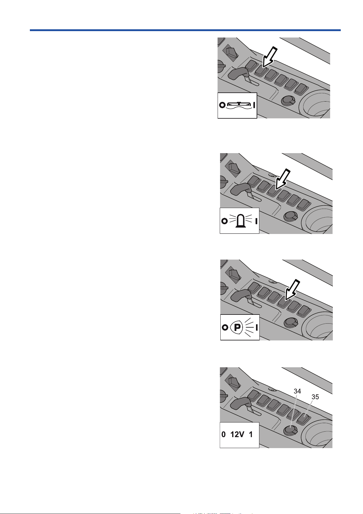
34-35.Power outlet
A seat heater or mobile phone charger are examples
of articles that can be connected to the power socket (34).
The power outlet is switched on and off using power
switch (35) on the control panel.
The electrical outlet socket is fuse protected by its own
fuse FU11 (max. 10 A), which is located behind a
cover on the outside of the control panel.
23
Loading...