

Page 1

Gasoline containing up to 10% ethanol (E10) is
acceptable for use in this machine. The use of any
gasoline exceeding 10% ethanol (E10) will void
the product warranty.
Operator Manual
PZ6034FX ZT / 966614601
Please read the operator’s manual carefully and make sure you
understand the instructions before using the machine.
Page 2

When this product is worn out and no longer used, it
should be returned to the reseller or other party for
recycling.
To implement improvements, specifications and designs can be altered without prior notification.
Note that no legal demands can be placed based on the information contained in these instructions.
Use only original parts for repairs. The use of other parts voids the warranty.
Do not modify or install non-standard equipment to the unit without consent from the manufacturer.
Modifications to the unit may cause unsafe operations or damage the unit.
©2011. All rights reserved.
Orangeburg, SC. Printed in U.S.A.
Page 3

CONTENTS
INTRODUCTION ............................................................... 5
Driving and Transport on Public Roads ...................... 5
Towing .........................................................................5
Operating ....................................................................5
Good Service .............................................................. 6
Manufacturing Number ......................................... 6
SYMBOLS AND DECALS .................................................. 7
SAFETY ............................................................................. 9
Safety Instructions ...................................................... 9
Personal Safety Equipment ......................................11
Slope Operation ........................................................11
Safe Handling of Gasoline ........................................ 13
General Maintenance ............................................... 14
Towing .......................................................................16
Transport ................................................................... 16
Rollover Protection System (ROPS) .......................... 17
Spark Arrestors ......................................................... 17
CONTROLS ..................................................................... 18
Control Locations ......................................................18
Motion Control Levers ...............................................19
Parking Brake ........................................................... 20
Throttle Control ......................................................... 20
Blade Switch ............................................................. 20
Ignition Switch ..........................................................21
Choke Control ........................................................... 22
Fuses ........................................................................ 22
Hour Meter ................................................................ 22
Tracking Knob .......................................................... 23
Cutting Height Pedals ...............................................23
Seat Adjustment Lever .............................................24
Fuel Shut Off Valve ................................................... 24
Fuel Tank ...................................................................25
OPERATION .................................................................... 26
Training ..................................................................... 26
Steering ....................................................................26
Roll Bar and Safety Belt ............................................ 27
Before Starting .......................................................... 27
Starting the Engine ................................................... 28
Jumper Cables Use ............................................ 32
Running ....................................................................33
Operating on Hills ..................................................... 34
Mowing Tips .............................................................35
Stopping the Engine ................................................. 36
Moving Machine By Hand ........................................ 37
Bypass Valves ..................................................... 37
MAINTENANCE ............................................................... 38
Battery ......................................................................40
Safety System ........................................................... 41
Fuel Filter .................................................................. 41
Tire Pressures ........................................................... 41
Parking Brake ........................................................... 42
Parking Brake Adjustments ................................42
Deck Belt .................................................................. 44
Pump Belt ................................................................. 45
V-belts ....................................................................... 45
Cutting Blades .......................................................... 46
Adjusting the Mower Deck .......................................47
Leveling Deck ..................................................... 47
Anti-scalp Rollers ................................................ 48
Caster Wheels ..........................................................48
Hardware .................................................................. 49
Cleaning ...................................................................49
LUBRICATION ................................................................. 50
Lubrication Schedule ................................................ 50
Wheel and Deck Zerks ............................................. 51
Front Wheel Mount .............................................. 51
Front Wheel Bearings .........................................51
Deck Spindle ......................................................51
Cables ......................................................................51
Hydraulic Drive - ZT5400 .......................................... 52
Fluid and Filter Change ......................................52
Transmission Purging Procedures ............................ 53
TROUBLESHOOTING GUIDE ......................................... 54
STORAGE .......................................................................56
Winter Storage .......................................................... 56
Service ...................................................................... 56
WIRING DIAGRAMS .......................................................57
TECHNICAL DATA .......................................................... 58
Torque Specifications ............................................... 60
CONFORMITY CERTIFICATES ........................................ 61
SERVICE JOURNAL ........................................................ 62
Page 4

WARNING!
Failure to follow cautious operating practices can result in serious injury to the
operator or other persons. The owner must understand these instructions, and must
allow only trained persons who understand these instructions to operate the mower.
Each person operating the mower must be of sound mind and body and must not be
under the influence of any mind altering substance.
WARNING!
Engine exhaust, some of its constituents, and certain vehicle components contain or
emit chemicals known to the State of California to cause cancer and birth defects or
other reproductive harm.
WARNING!
Battery posts, terminals and related accessories contain lead and lead compounds,
chemicals known to the State of California to cause cancer and birth defects or other
reproductive harm. Wash hands after handling.
Page 5

INTRODUCTION
Congratulations
Thank you for purchasing a Husqvarna ride-on
mower. This machine is built for superior efficiency
to rapidly mow primarily large areas. A control panel
easily accessible to the operator and a hydrostatic
transmission regulated by steering controls both
contribute to the machine’s performance.
This manual is a valuable document. Read the
contents carefully before using or servicing the
machine. The following of instructions (use, service,
maintenance) by all who operate this machine is
important for the safety of the operator and others.
It can also considerably increase the life span of the
machine and increase its resale value.
If you sell your machine, be sure to give the operator’s
manual to the new owner.
The final chapter of this operator’s manual provides a
Service Journal. Ensure that service and repair work
are documented. A well-kept service journal reduces
service costs for the maintenance and affects the
machine’s resale value. Please contact your dealer for
more information. Take the operator’s manual along
when the machine is taken to your dealer for service.
General
In this operator’s manual, left and right, backward and
forward are used in relation to the machine’s normal
driving direction.
Continuous dedication to improve our products
require that specifications and design are subject to
change without notice.
Driving and Transport on Public Roads
Check applicable road traffic regulations before
transporting on public roads. If the machine is
transported, you must always use approved fastening
equipment and ensure that the machine is well
anchored. DO NOT operate this machine on public
roadways.
Towing
If machine is equipped with a tow hitch, use extreme
caution when towing. Never allow children or others in
or on the towed equipment. Make wide turns to avoid
jack-knifing. Travel slowly and allow extra distance to
stop.
Do not tow on sloped ground. The weight of the towed
equipment may cause loss of traction and loss of
control.
Follow the manufacturer's recommendation for weight
limits for towed equipment. Do not tow near ditches,
canals, and other hazards.
Operating
This machine is constructed only for mowing grass
on lawns and even ground without obstacles such
as stones, tree stumps, etc. The machine can also
be used for other tasks when equipped with special
accessories provided by the manufacturer. Operating
instructions for the accessories are provided with
delivery. All other types of uses are incorrect. The
manufacturer’s directions concerning operation,
maintenance, and repairs must be carefully followed.
Lawn mowers and all power equipment can be
potentially dangerous if used improperly. Safety
requires good judgment, careful use in accordance
with these instructions and common sense.
The machine must only be operated, maintained,
and repaired by persons familiar with the
machine’s special characteristics and who are also
knowledgeable about the safety instructions. Use only
approved repair parts to maintain this machine.
Accident prevention regulations, other general safety
regulations, occupational safety rules, and traffic
regulations must be followed without fail.
Unauthorized modifications to the design of the
machine may absolve the manufacturer from liability
for any resulting personal injury or property damage.
5
Page 6

INTRODUCTION
Good Service
Husqvarna’s products are sold all over the world
and only in specialized retail stores with complete
service. This ensures that you as a customer receive
only the best support and service. Before the product
is delivered, the machine has, for example, been
inspected and adjusted by your retailer. See the
certificate in the Service Journal in this operator’s
manual.
When you need spare parts or support in service
questions, warranty issues, etc., please consult
the following professional:
This manual belongs to the machine with the
manufacturing number:
Manufacturing Number
The machine’s manufacturing number can be found
on the printed plate affixed to the right side in the
engine compartment. Stated on the plate, from the top
are:
• The machine’s type designation (I.D.).
• The manufacturer’s type number (Model).
• The machine’s serial number (Serial no.)
Please have the type designation and serial number
available when ordering spare parts.
The engine’s manufacturing number is stamped either
on one of the valve covers or an affixed serial plate.
The plate states:
• The engine’s model.
• The engine’s type.
• Code
Please have these available when ordering spare
parts.
The wheel motors and hydrostatic pumps have a
barcode decal affixed at the rear.
Engine Transmission
6
Page 7
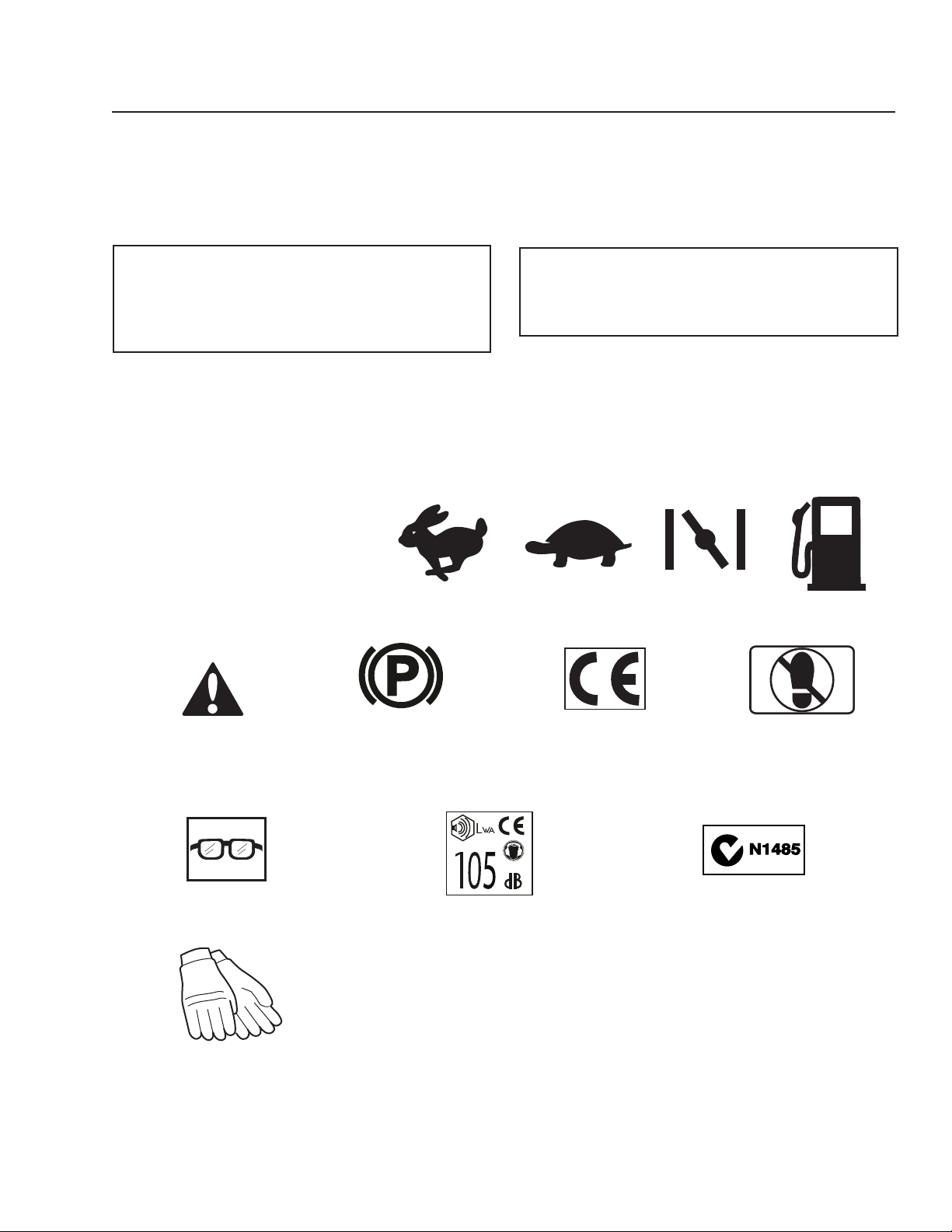
SYMBOLS AND DECALS
These symbols are found on the machine and in the
operator’s manual.
Study them carefully so that you know what they
mean.
WARNING!
Xxxx xxxxxx xxxxx xxxx xxxxxxxxx
xxxxxx xxxxxxxxx. xx xxxxxxxx xxxx
xxxxxx.
Used in this publication to notify the reader of a risk
of personal injury or death, particularly if the reader
should neglect to follow instructions given in the
manual.
IMPORTANT INFORMATION
Xxxx xxxxxx xxxxx xxxx xxxxxxxxx xxxxxx
xxxxxxxxx. xx xxxxxxxx xxxx xxxxxx.
Used in this publication to notify the reader of a risk
of material damage, particularly if the reader should
neglect to follow instructions given in the manual.
Used also when there is a potential for misuse or
misassembly.
R N
Reverse Neutral Fast Slow Choke Fuel
Warning! Parking Brake CE conformity
marking. Only for
European market
Use protective glasses
Noise emissions to the surroundings
in accordance with the European
Union’s directive. The machine’s
emission is stated in the chapter
TECHNICAL DATA and on the
decals.
Only machines for European market
Use protective gloves
Do not stand here
Electromagnetic
Compatibility (EMC)
Compliance
Australia and
New Zealand only
7
Page 8
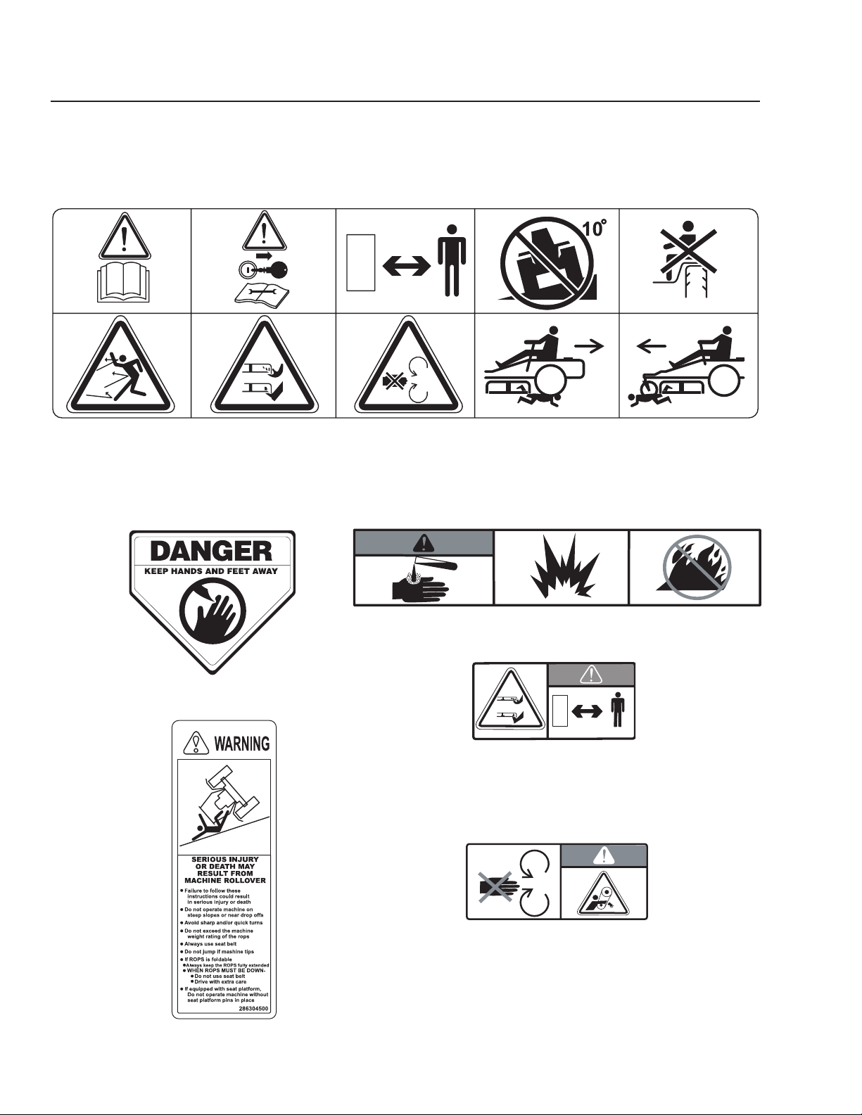
Read Operator’s
Manual
SYMBOLS AND DECALS
Shut off engine and
remove key before
performing any
maintenance or repair
work
Keep a safe
distance from the
machine
Use on slopes no
greater than 10° No passengers
Whole body
exposure to
thrown objects
Moving sharp blades under cover
Severing of fingers
and toes
Do not open or
remove safety
shields while
engine is running
Battery acid is corrosive, explosive and flammable
Careful backing up,
watch for other
people
Warning! Rotating blades,
keep away from the
discharge deck
Careful going
forward, watch for
other people
Do not touch parts
8
Page 9
Safety Instructions
These instructions are for your safety. Read them
carefully.
SAFETY
WARNING!
THIS CUTTING MACHINE IS CAPABLE
OF AMPUTATING HANDS AND FEET
AND THROWING OBJECTS. FAILURE
TO OBSERVE THE FOLLOWING
SAFETY INSTRUCTIONS COULD
RESULT IN SERIOUS INJURY OR
DEATH.
General Operation
• Read, understand, and follow all instructions on
the machine and in the manual before starting.
• It is recommended that someone be aware that
you are mowing and can provide help in case of
injury or accident.
• Do not put hands or feet near rotating parts or
under the machine. Keep clear of the discharge
opening at all times.
• Only allow responsible adults, who are familiar
with the instructions, to operate the machine.
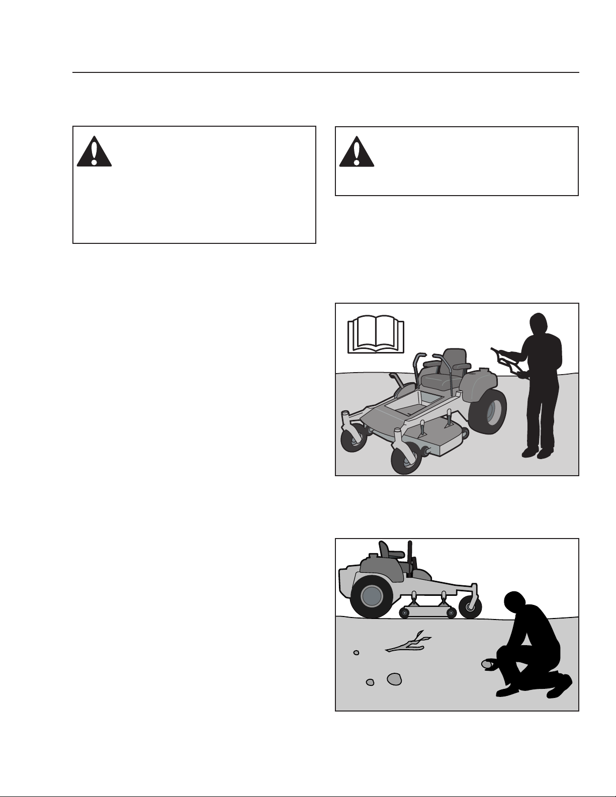
• Clear the area of objects such as rocks, toys, wire,
etc., which could be picked up and thrown by the
blades.
• Be sure the area is clear of bystanders before
operating. Stop machine if anyone enters the
area.
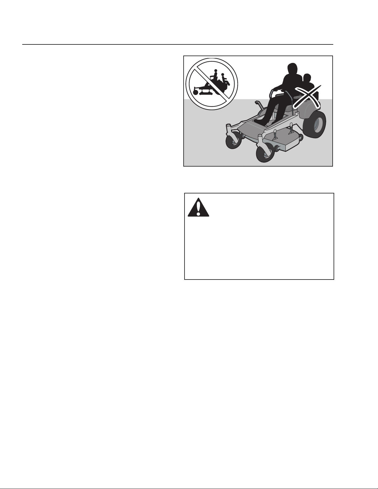
• Never carry passengers. The machine is only
intended for use by one person.
• Do not mow in reverse unless absolutely
necessary. Always look down and behind before
and while backing.
• Never direct discharged material toward anyone.
Avoid discharging material against a wall or
obstruction. Material may ricochet back toward
the operator. Stop the blades when crossing
gravel surfaces.
• Do not operate machine without the entire grass
catcher, discharge guard, or other safety devices
in place and working
• Slow down before turning.
• Never leave a running machine unattended.
Always turn off blades, set parking brake, stop
engine, and remove keys before dismounting.
WARNING!
This symbol means that important
safety instructions need to be
emphasized. It concerns your safety.
0000-000
Read the operator’s manual before starting the machine
Clear the area of objects before mowing
0000-000
9
Page 10
SAFETY
• Disengage blades when not mowing. Shut
off engine and wait for all parts to come to a
complete stop before cleaning the machine,
removing the grass catcher, or unclogging the
discharge guard.
• Operate machine only in daylight or good artificial
light.
• Do not operate the machine while under the
influence of alcohol or drugs.
• Watch for traffic when operating near or crossing
roadways.
• Use extra care when loading or unloading the
machine into a trailer or truck.
• Always wear eye protection when operating
machine.
• Wear proper Personal Protective Equipment
(PPE) while operating this machine, including (at
a minimum) sturdy footwear, eye protection, and
hearing protection. Do not mow in shorts and/or
footwear with open toes.
• Data indicates that operators age 60 years and
above are involved in a large percentage of riding
mower-related injuries. These operators should
evaluate their ability to operate the riding mower
safely enough to protect themselves and others
from serious injury.
• Follow the manufacturer’s recommendation for
wheel weights or counterweights.
• Anyone who operates this machine must first read
and understand this Operation Manual. Local laws
may regulate the age of the user.
• Keep machine free of grass, leaves or other
debris buildup which can touch the hot exhaust or
engine parts and burn.
• Do not allow the mower deck to plow leaves or
other debris, causing buildup to occur.
• Clean any oil or fuel spillage before operating or
storing the machine.
• Allow machine to cool before storage.
8011-520
Never take passengers
WARNING!
Engine exhaust and certain vehicle
components contain or emit chemicals
considered to cause cancer, birth
defects, or other reproductive system
damage. The engine exhaust contains
carbon monoxide, which is an
odorless, colorless, poisonous gas.
Do not use the machine in enclosed
spaces.
10
Page 11
SAFETY
Personal Safety Equipment
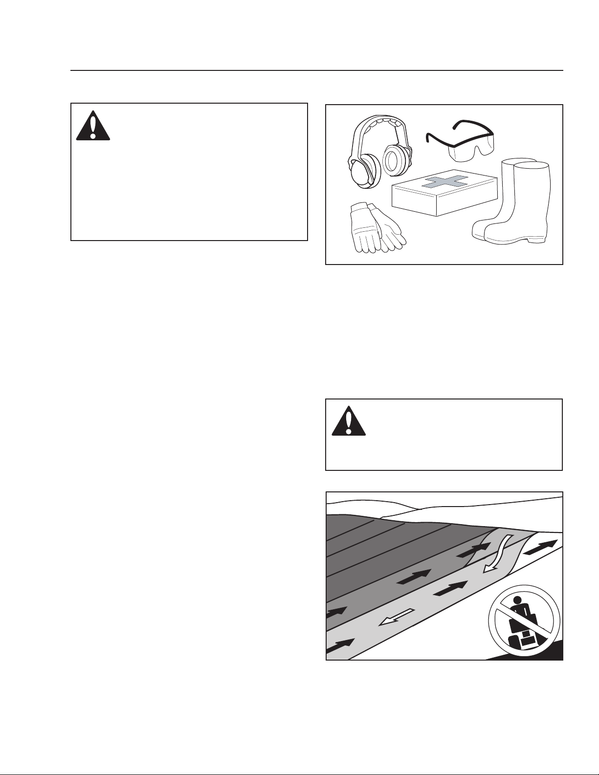
WARNING!
When using the machine, approved
personal protective equipment (shown
in illustrations) shall be used. Personal
protective equipment cannot eliminate
the risk of injury but it will reduce the
degree of injury if an accident does
happen. Ask your retailer for help in
choosing the right equipment.
• Make sure that you have first aid equipment close
at hand when using the machine.
• Never use the machine when barefoot.
• Always wear protective shoes or boots, preferably
with steel toe caps.
• Always wear approved protective glasses or a full
visor when assembling or driving.
• Always wear gloves when handling the blades.
• Never wear loose clothing that can get caught in
moving parts.
• Use ear protectors to avoid damage to hearing.
0000-000a
Personal protective equipment
Slope Operation
Slopes are a major factor related to loss of control and
tip-over accidents, which can result in severe injury or
death. Operation on all slopes requires extra caution.
If you cannot back up the slope or if you feel uneasy
on it, do not mow it.
• Mow up and down slopes (10 degrees maximum),
not across.
• Watch for holes, ruts, bumps, rocks, or other
hidden objects. Uneven terrain could overturn the
machine. Tall grass can hide obstacles.
• Choose a low ground speed so that you will not
have to stop while on the slope.
• Do not mow on wet grass. Tires may lose traction.
• Avoid starting, stopping, or turning on a slope. If
the tires lose traction, disengage the blades and
proceed slowly straight down the slope.
• Keep movement on the slopes slow and gradual.
Do not make sudden changes in speed or
direction, which could cause machine to roll over.
• Use extra care while operating machine with
grass catchers or other attachments; they can
affect the stability of the machine.
WARNING!
Do not drive up or down hills with
slopes greater than 10 degrees. And do
not drive across any slopes.
0000-000
Mow up and down, not side to side
11
Page 12
SAFETY
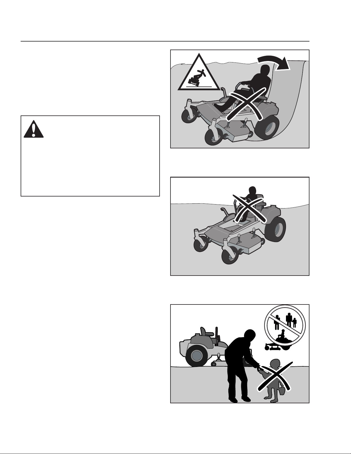
• Do not use on steep slopes.
• Do not try to stabilize the machine by putting a
foot on the ground.
• Do not mow near drop-offs, ditches, or
embankments. The machine could suddenly roll
over if a wheel is over the edge or if the edge
caves in.
WARNING!
CHILDREN CAN BE INJURED BY
THIS EQUIPMENT. The American
Academy of Pediatrics recommends
that children be a minimum of 16
years of age before operating a riding
lawn mower. Keep children out of the
mowing area and in the watchful care
of a responsible adult other than the
operator.
0000-000
Be extra cautious when driving on slopes
Children
Tragic accidents can occur if the operator is not
alert to the presence of children. Children are often
attracted to the machine and the mowing activity.
Never assume that children will remain where you last
saw them.
• Keep children out of the mowing area and in the
watchful care of a responsible adult other than the
operator.
• Be alert and turn machine off if a child enters the
area.
• Before and while backing, look behind and down
for small children.
• Never carry children, even with the blades shut
off. They may fall off and be seriously injured or
interfere with safe machine operation. Children
who have been given rides in the past may
suddenly appear in the mowing area for another
ride and be run over or backed over by the
machine.
• Never allow children to operate the machine.
• Use extra care when approaching blind corners,
shrubs, trees, or other objects that may block your
view of a child.
0000-000
Never allow children to operate the machine
12
0000-000
Keep children away from work area
Page 13
SAFETY
Safe Handling of Gasoline
WARNING!
The engine and the exhaust system
become very hot during operation.
There is risk for burns if touched.
Allow engine and exhaust system to
cool before refueling.
To avoid personal injury or property damage, use
extreme care in handling gasoline. Gasoline is
extremely flammable and the vapors are explosive.
• Extinguish all cigarettes, cigars, pipes, and other
sources of ignition.
• Use only approved gasoline containers.
• Never remove gas cap or add fuel with the engine
running. Allow engine to cool before refueling.
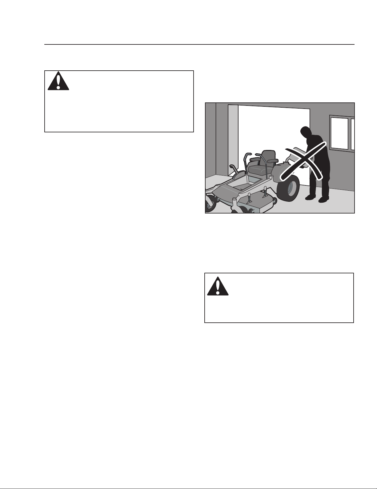
• Never fuel the machine indoors.
• Never store the machine or fuel container where
there is an open flame, spark, or pilot light such
as on a water heater or other appliance.
• Before you begin refueling, minimize the risk of
static electricity by touching a metal surface.
• Never fill containers inside a vehicle or on a truck
or trailer bed with plastic liner. Always place
containers on the ground away from the vehicle
when filling.
• Remove gas-powered equipment from the truck
or trailer and refuel it on the ground. If this is not
possible, refuel such equipment with a portable
container, rather than from a gasoline dispenser
nozzle.
• Keep the nozzle in contact with the rim of the fuel
tank or container opening at all times until fueling
is complete. Do not use a nozzle lock-open
device.
• If fuel is spilled on clothing, change clothing
immediately.
• Never overfill fuel tank. Replace gas cap and
tighten securely.
• Do not start the engine near spilled fuel.
• Never use gasoline as a cleaning agent.
• If leaks arise in fuel system, engine must not be
started until problem has been resolved.
• Check the fuel level before each use and leave
space for the fuel to expand, as the heat from the
engine and the sun may otherwise cause the fuel
to expand and overflow.
8011-516
Never fill the fuel tank indoors
WARNING!
The engine must not be started
when the driver’s floor plate or any
protective plate for the mower deck’s
drive belt is removed.
13
Page 14
SAFETY
General Maintenance
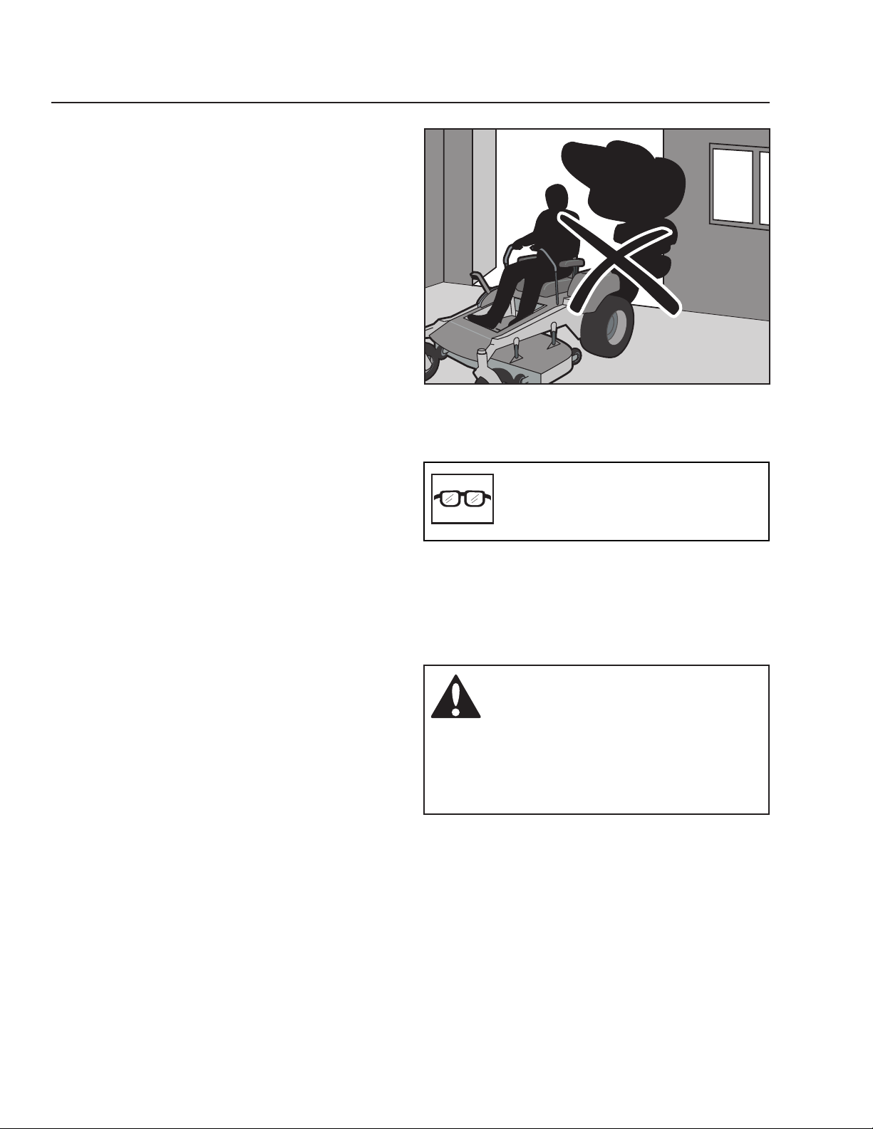
• Never operate machine in a closed area.
• Keep all nuts and bolts tight to be sure the
equipment is in safe working condition.
• Never tamper with safety devices. Check their
proper operation regularly.
• Keep machine free of grass, leaves, or other
debris buildup. Clean oil or fuel spillage and
remove any fuel-soaked debris. Allow machine to
cool before storing.
• If you strike a foreign object, stop and inspect the
machine. Repair, if necessary, before restarting.
• Never make any adjustments or repairs with the
engine running.
• Check grass catcher components and the
discharge guard frequently and replace with
manufacturer’s recommended parts, when
necessary.
• Mower blades are sharp. Wrap the blade or wear
gloves, and use extra caution when servicing
them.
• Check brake operation frequently. Adjust and
service as required.
• Maintain or replace safety and instruction labels,
as necessary.
• Do not modify safety equipment. Check regularly
to be sure it works properly. The machine must not
be driven with defective or unmounted protective
plates, protective cowlings, safety switches, or
other protective devices.
• Do not change the settings of governors and
avoid running the engine with overly high engine
speeds. If you run the engine too fast, you risk
damaging the machine components.
• Be very careful when handling battery acid. Acid
on skin can cause serious corrosive burns. If you
spill battery acid on your skin, rinse immediately
with water.
• Acid in the eyes can cause blindness, contact a
doctor immediately.
• Be careful when servicing the battery. Explosive
gases form in the battery. Never perform
maintenance on the battery when smoking or near
open flames or sparks.
• The battery can explode and cause serious injury
or damage.
• Make sure that the equipment is in good condition
and that all nuts and bolts, especially those
fastening the blade attachments, are properly
tightened and torqued.
8011-515
Never drive the machine in an enclosed space
CAUTION!
Use protective glasses for
maintenance work.
WARNING!
The battery contains lead and lead
compounds, chemicals that are
considered to cause cancer, birth
defects, and other reproductive system
damage. Wash your hands after
handling the battery.
14
Page 15
SAFETY
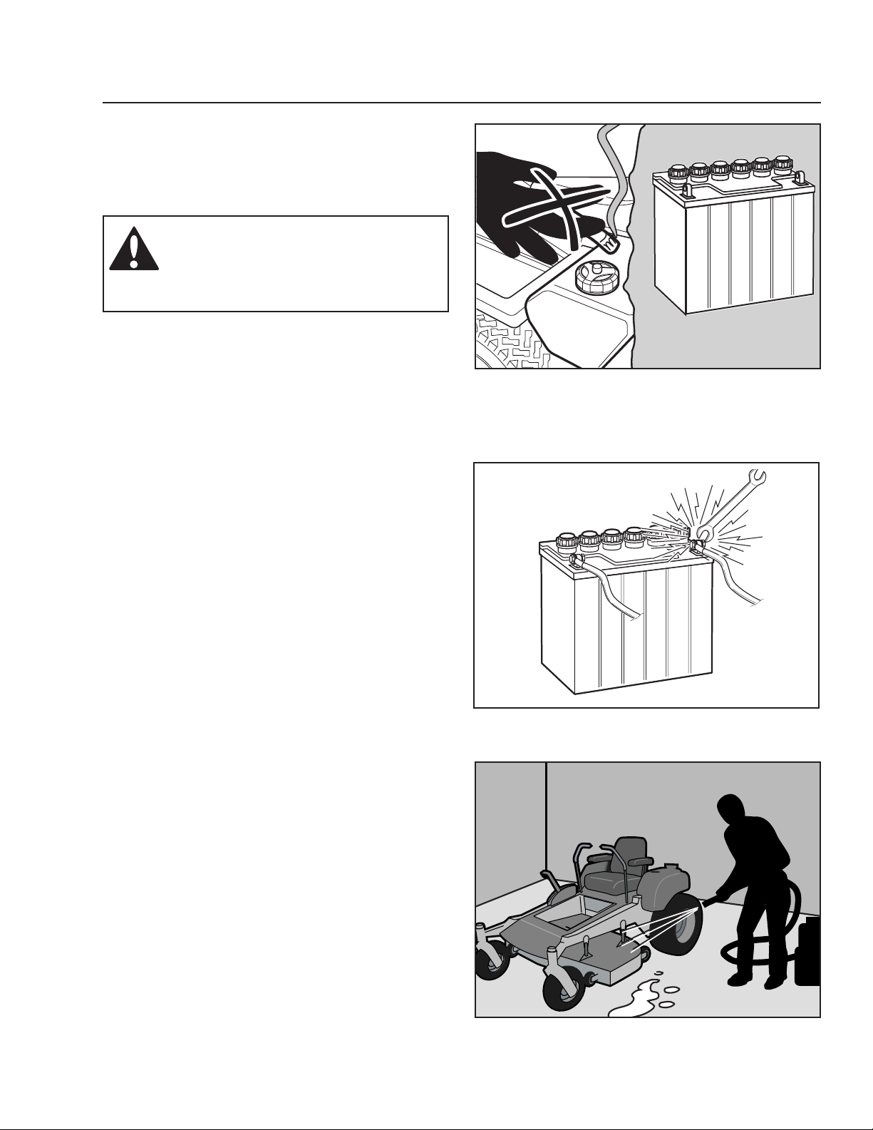
Sparking can occur when working with the battery
and the heavy cables of the starter circuit. This can
cause battery explosion, fire or eye injury. Sparking
in this circuit can not occur after the chassis cable
(normally negative, black) is removed from the battery.
WARNING!
Avoid electrical sparking and its
consequences by the following
routines:
• Use protective goggles.
• Ensure that the fuel filler cap is mounted tightly
and no flammable substances are stored in an
open vessel.
• Never work with the starter circuit if there is spilled
fuel.
• Disconnect the chassis cable from the battery first
and reconnect it last.
• Do not make a bridge short circuit across the
starter relay to run the starter.
0000-000
Do not smoke when performing maintenance on the battery.
The battery can explode and cause serious injury/damage.
• Never use the machine indoors or in spaces
lacking proper ventilation. The exhaust fumes
contain carbon monoxide, an odorless,
poisonous, and lethal gas.
• Stop to inspect the equipment if you run over or
into anything. If necessary, make repairs before
starting.
• Never make adjustments with the engine running.
• The machine is tested and approved only with the
equipment originally provided or recommended
by the manufacturer. Only use approved repair
parts for the machine.
• The blades are sharp and can cause cuts and
gashes. Wrap the blades or use protective gloves
when handling them.
• Check the parking brake functions regularly.
Adjust and service as necessary.
• Mulch blades should only be used in familiar
areas when higher quality mowing is desired.
• Reduce the risk of fire by removing grass, leaves,
and other debris that may have accumulated on
the machine.
• Allow the machine to cool before putting it in
storage.
• Regularly clean deck and underside of deck,
avoid spraying engine and electrical components
with water.
8009-728
Risk of sparking
8011-514
Regularly clean deck
15
Page 16
SAFETY
Transport
1. The machine is heavy and can cause serious
crushing injuries. Be extra cautious when it is
loaded on or unloaded from a vehicle or trailer.
2. Use an approved trailer to transport the machine.
Activate the parking brake, turn off the fuel supply,
and fasten the machine with approved fastening
devices, such as bands, chains, or straps, when
transporting.
3. Do not operate this machine on public roadways.
4. Check and abide by local traffic regulations
before transporting the machine on any road.
5. Do not tow this machine, it may cause damage to
the drive system.
6. Load the unit onto truck or trailer by driving up
ramps of suitable strength using a slow speed. Do
not lift! The machine is not intended to be lifted by
hand.
7. When loading or unloading this machine, do not
exceed the maximum recommended operation
angle of 10O.
WARNING!
Use extreme caution when loading the
machine into a truck or trailer using
ramps. There is the possibility of
serious injury or death if the machine
falls off the ramps.
IMPORTANT INFORMATION
The parking brake is not sufficient to lock the
machine in place during transport. Ensure that
the machine is well fastened to the transport
vehicle. Always reverse the machine onto the
transport vehicle to avoid tipping it over.
Towing
If machine is equipped with a tow hitch, use extreme
caution when towing. Never allow children or others in
or on towed equipment.
Make wide turns to avoid jack-knifing. Travel slowly
and allow extra distance to stop. Do not tow on sloped
ground. The weight of the towed equipment may
cause loss of traction and loss of control.
Follow the manufacturer’s recommendation for weight
limits for towed equipment. Do not tow near ditches,
canals, and other hazards.
WARNING!
Escaping hydraulic oil under pressure
can have sufficient force to penetrate
the skin, causing serious injury.
If injured by escaping fluid, see a
doctor at once. Serious infection
or reaction can develop if proper
medical treatment is not administered
immediately.
WARNING!
This mower is equipped with an
internal combustion engine and
should not be used on or near any
unimproved forested, bush covered
or grassy lands unless the engine's
system is equipped with a spark
arrester meeting applicable local or
state laws (if any). If a spark arrestor
is used, it should be maintained
in effective working order by the
operator.
16
Page 17
SAFETY
Rollover Protection System (ROPS)
The ROPS increases the basic weight of the unit by 73
lbs/33 kg.
• Do not use ROPS as a lifting, attaching or
anchoring point.
• Do not use ROPS for wrecking or towing.
• Do not exceed Max GVW: 2822 lbs/1283 kg.
• Read machine’s operator manual before each
use.
• Securely fasten the seat belt if the unit has a
ROPS.
• Where possible, avoid operating the unit near
ditches, embankments and holes.
• Reduce speed when turning, crossing slopes and
on rough, slick or muddy surfaces.
• Stay off slopes too steep for safe operation.
• Watch where you are going, especially at row
ends, on roads and around trees.
• Do not permit others to ride.
• Operate the mower smoothly - no jerky turns,
starts or stops.
• When mower is stopped, set brakes securely and
use park brake.
• If any part of ROPS is damaged, the entire ROPS
must be replaced.
• Check all bolts including seat belt for correct
torque before each use.
• Check ROPS structure for damage before each
use.
• ROPS bar is NOT intended for use in sub zero
temperatures.
WARNING!
The rollover protection system's
capabilities may be impaired by
damage if the mower is overturned
or if alteration to the ROPS occurs. If
these conditions take place, the total
structure MUST be replaced.
WARNING!
This mower is equipped with an
internal combustion engine and
should not be used on or near any
unimproved forested, bush covered
or grassy lands unless the engine's
system is equipped with a spark
arrester meeting applicable local or
state laws (if any). If a spark arrestor
is used, it should be maintained
in effective working order by the
operator.
Spark Arrestors
A spark arrester is standard equipment on the unit
and is attached to the engine muffler. Clean the
interior screen regularly, depending on usage and
conditions.
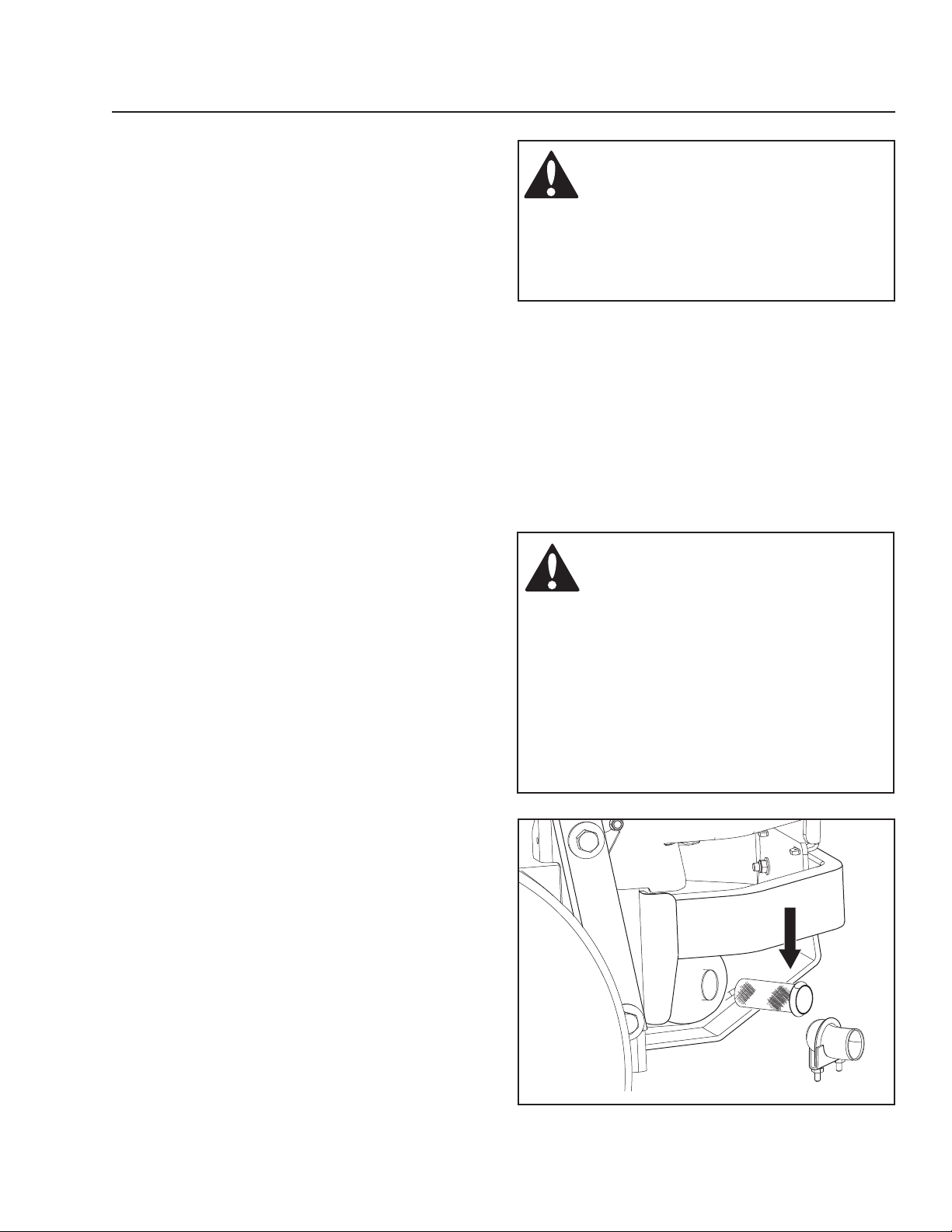
To clean, remove the clamp securing the tail pipe.
Remove the tail pipe and slide the spark arrestor
screen out of the muffler. Clean carbon from the
screen with a soft brush or cloth.
Replace screen and reattach the tail pipe, orienting
the tail pipe either horizontally or upwards, away from
grassy surfaces.
8011-514
Regularly clean spark arrestor screen
17
Page 18
CONTROLS
This operator’s manual describes the Husqvarna Zero
Turn Rider. The rider is fitted with a Kawasaki fourstroke overhead valve engine.
Transmission from the engine is made via belt-driven
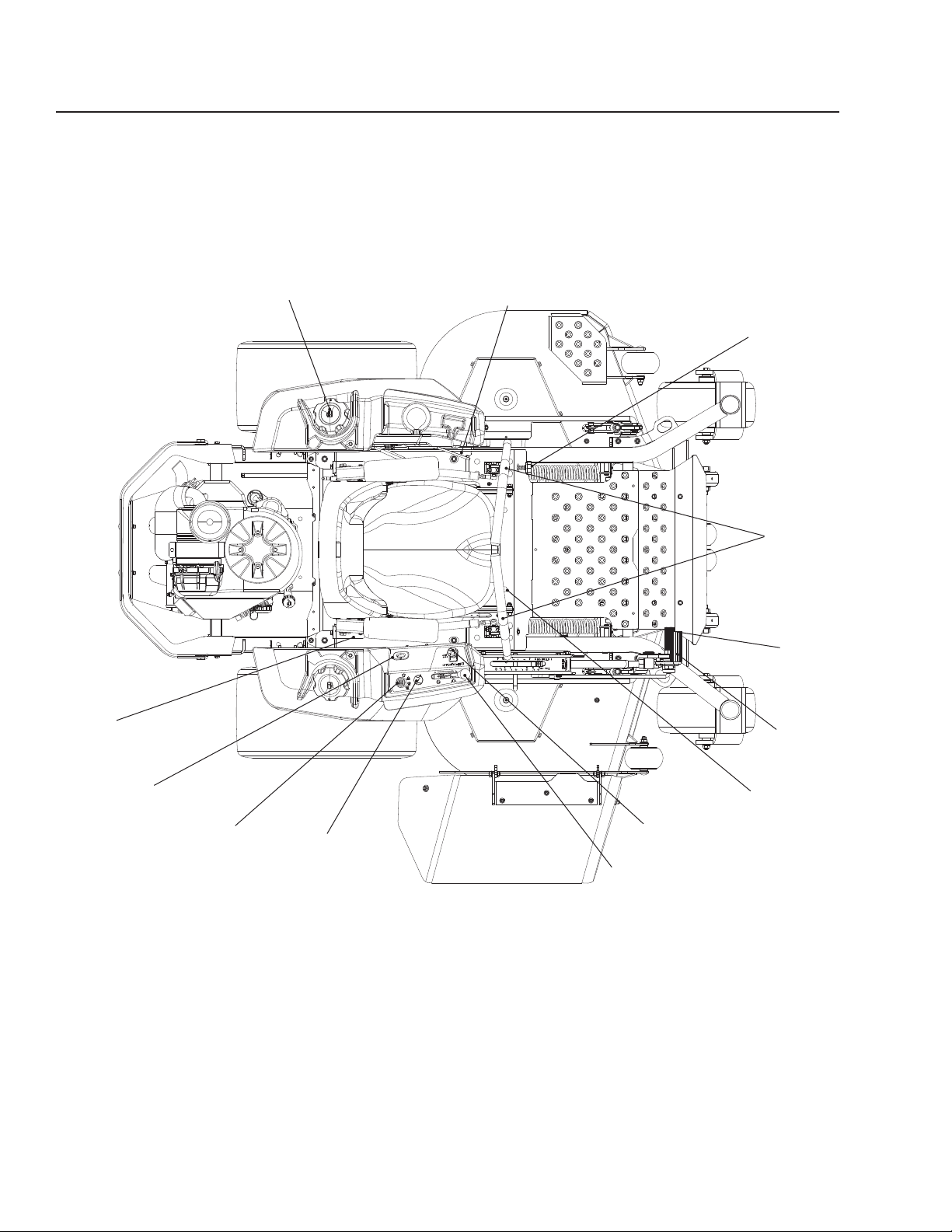
Control Locations
4
hydraulic pumps. Using the left and right steering
controls, the flow is regulated and thereby the
direction and speed.
3
2
1
13
5
6
7
8
1. Motion control levers
2. Tracking knob
3. Parking brake
4. Fuel tank cap - left
5. Fuses
6. Hour meter
8. Choke control
9. Throttle control
10. Blade switch
11. Seat adjustment lever
12. Deck lift
13. Deck release
10
9
12
8065-001
11
7. Ignition switch
18
Page 19
CONTROLS
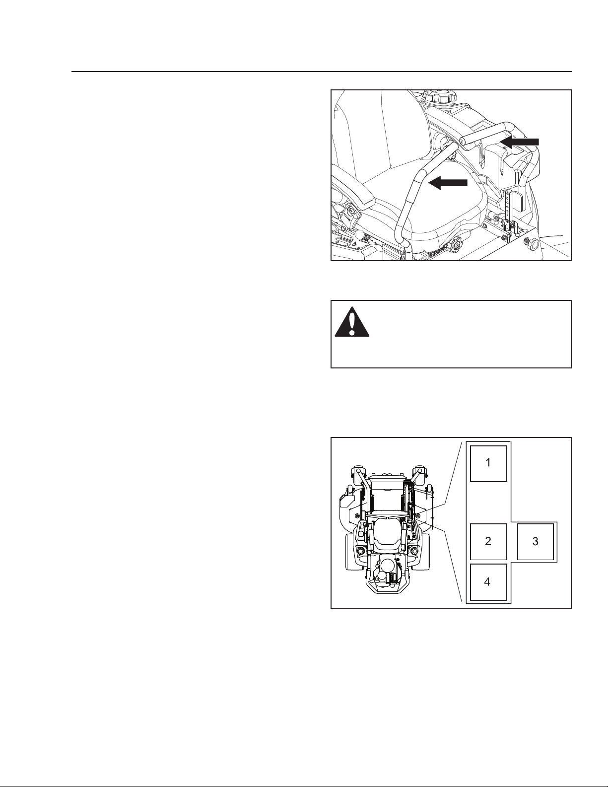
Motion Control Levers
The machine’s speed and direction are continuously
variable using the two steering controls. The steering
controls can be moved forward or backward about
a neutral position. Furthermore, there is a neutral
position, which is locked if the steering controls are
moved outward.
When both controls are in the neutral position (N), the
machine stands still.
By moving both controls an equal amount forward
or backward, the machine moves in a straight line
forward or backward respectively.
In order, for example, to turn right while moving
forward, move the right control towards the neutral
position. The rotation of the right wheel is reduced and
the machine turns to the right.
Zero turn can be achieved by moving one control
backward (behind the neutral position) and carefully
moving the other steering control forward from its
neutral position. The rotation direction when zero
turning is determined by which steering control is
moved backward behind the neutral position. If the left
steering control is pulled backward, the machine turns
to the left. Use extra care when using this maneuver.
If the steering controls are in uneven positions when
standing still or do not fit in the slots for moving the
controls outward, they can be adjusted.
8065-003
Steering controls
WARNING!
The machine can turn very rapidly if
one steering control is moved much
further forward than the other.
1. Forward
2. Neutral
3. Neutral slot, Neutral lock
4. Reverse
Motion control lever pattern (right side)
8065-053
19
Page 20
CONTROLS
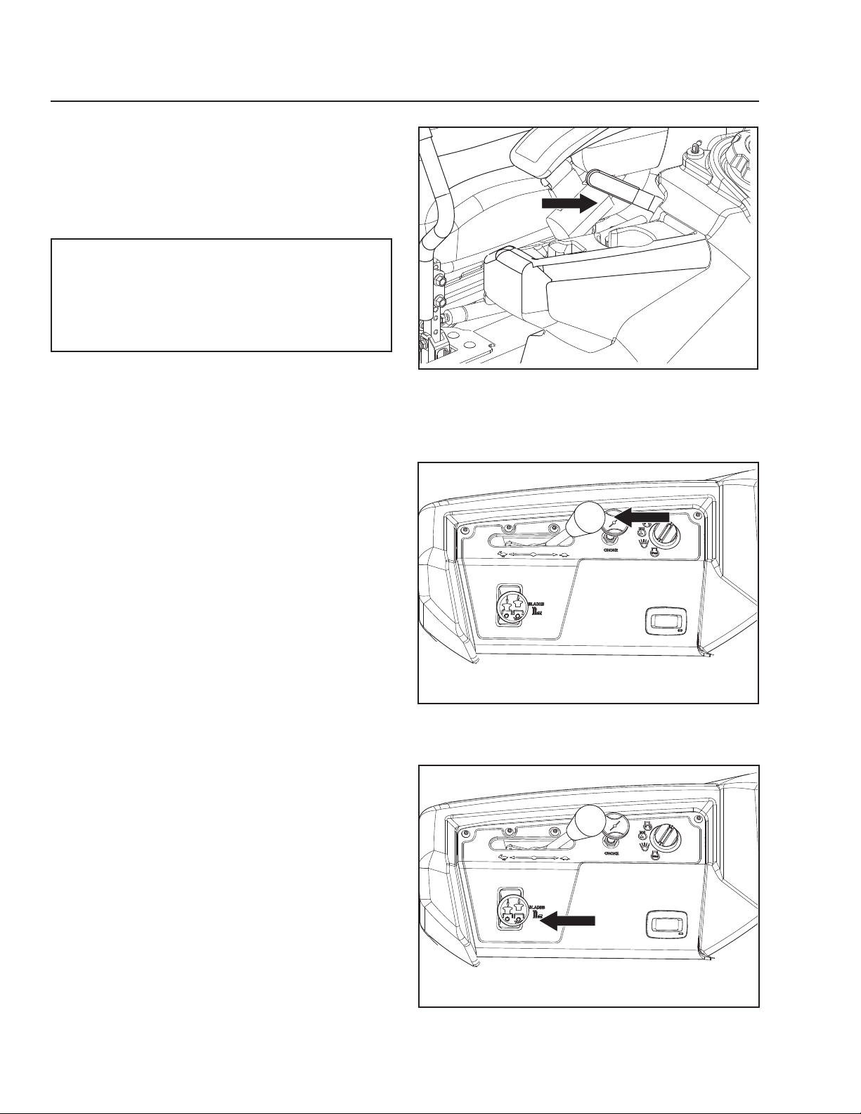
Parking Brake
The parking brake is found on the left of the machine.
Pull the lever backward to activate the brake and
forward to release it.
IMPORTANT INFORMATION
The machine must stand absolutely still when
applying the parking brake. Always set the
parking brake before dismounting. Release the
parking brake before moving the mower.
Throttle Control
The throttle control regulates the engine speed and
the rate of rotation of the blades, assuming the blade
switch is pulled out,
To increase or decrease the engine speed, the control
is moved forward or back respectively.
Avoid idling the engine for long periods, as there is a
risk of fouling the spark plugs.
USE FULL THROTTLE WHEN MOWING, for best
mower performance and battery charging.
8065-006
Parking brake
Blade Switch
To engage the mower deck, pull the blade switch
knob out. The mower blades are disengaged when
the knob is pressed down fully.
20
8065-004
Throttle control
8065-004
Blade switch
Page 21
CONTROLS
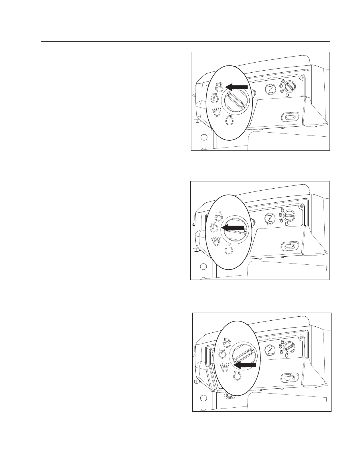
Ignition Switch
The ignition key is placed on the control panel and
is used to start and stop the engine. Turn the key
clockwise to start the engine.
Release the key to the RUN position when the engine
has started.
8065-058
Ignition switch
For using ACCESSORY, turn the key clockwise.
8065-059
Ignition switch - RUN position
8065-057
Ignition switch - accessory
21
Page 22
CONTROLS
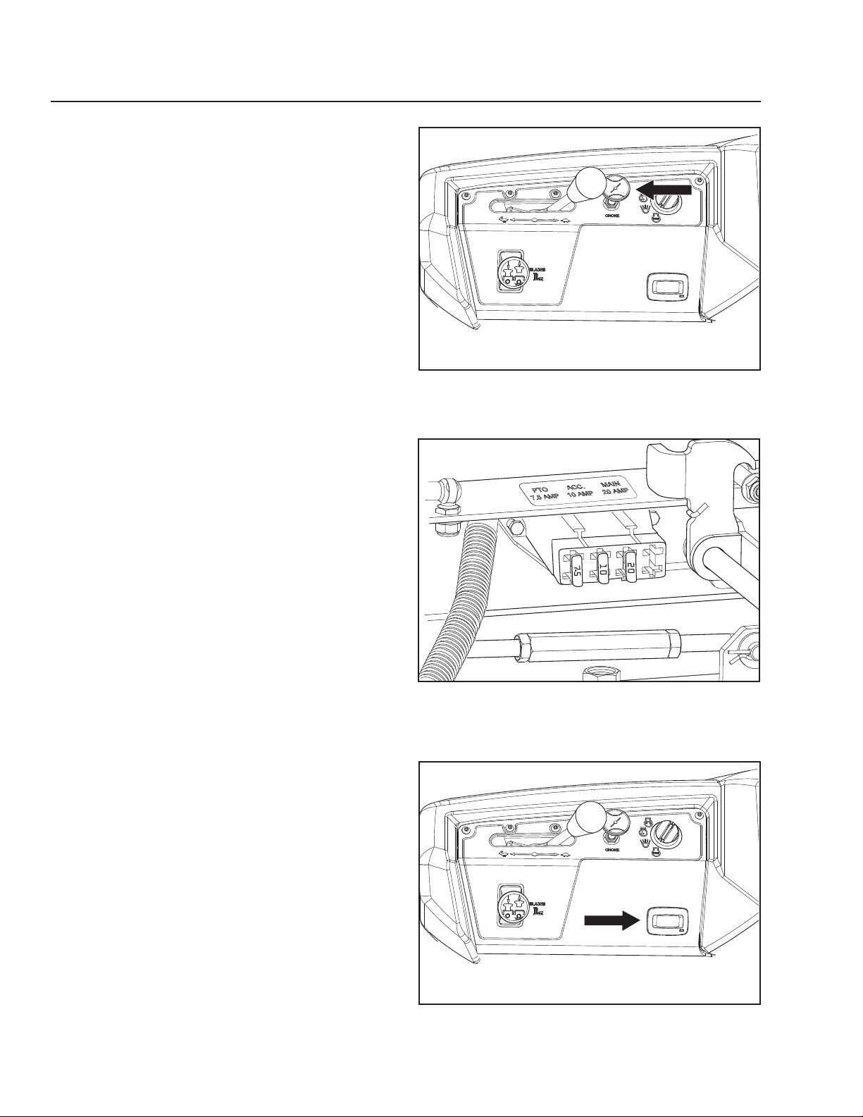
Choke Control
The choke control is used for cold starts in order to
provide the engine with a richer fuel mixture.
For cold starts the control should be pulled up.
Fuses
Fuses are located on the right hand side of the
machine. They are accessed by tilting the seat
forward. Fuses are flat pin fuses type as used in
automobiles.
There are three fuses with ratings and functions:
1. 20 A, Primary fuse.
2. 7.5 A, Mower deck coupling.
3. 10 A, Accessories
8065-004
Choke control
Hour Meter
The hour meter displays the total operating time.
It will flash CHG OIL (Change Oil) at 50 hour intervals.
The flash duration is one hour before and one hour
after the interval. The CHG OIL icon will come on
and shut off automatically. The hour meter cannot be
manually reset.
22
8065-043
Fuses
8065-004
Hour meter
Page 23
CONTROLS
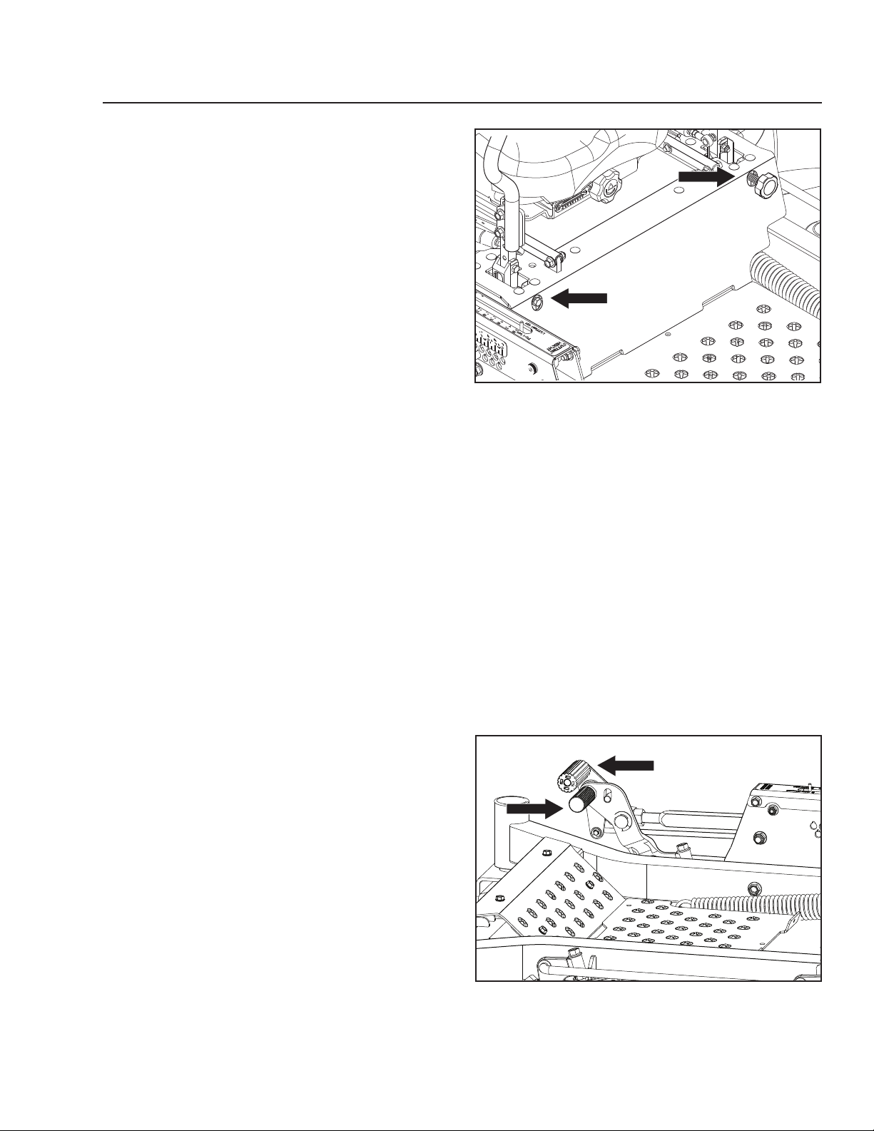
Tracking Knob
If the mower is not tracking straight, check the
air pressure in both rear tires. Recommended air
pressure for the rear tires is 15 psi (1 bar).
1. Tracking adjustments are made using the tracking
bolt and tracking knob. The tracking bolt and
tracking knob act as limiting devices for the
motion control levers when in the full-forward
position.
2. For preliminary tracking adjustment, move unit
to an open, unobstructed area such as an empty
parking lot or open field.
3. Back the tracking bolt out until flush with nut.
4. Loosen tracking knob out until flush with nut.
5. Test operate unit by driving it at full throttle and
the full forward position on both motion control
levers. Gradually turn in the tracking bolt on the
right hand side until the unit noticeably starts
drifting right.
6. Drive forward at full throttle with both motion
control levers in the full forward position.
Gradually turn in the tracking knob (left side) until
unit tracks straight.
8065-060
Tracking adjustment
Cutting Height Pedals
The cutting height pedals release the deck lift to allow
setting the desired deck height. Apply pressure to the
lift pedal and rotate foot to also apply pressure to the
release pedal, unlocking the deck lift.
For transport, push the lift pedal fully forward until the
deck lift latches in the transport (highest) position.
2
1
8065-017
1. Lift pedal
2. Release pedal
Cut height selection pedals
23
Page 24
CONTROLS
Seat Adjustment Lever
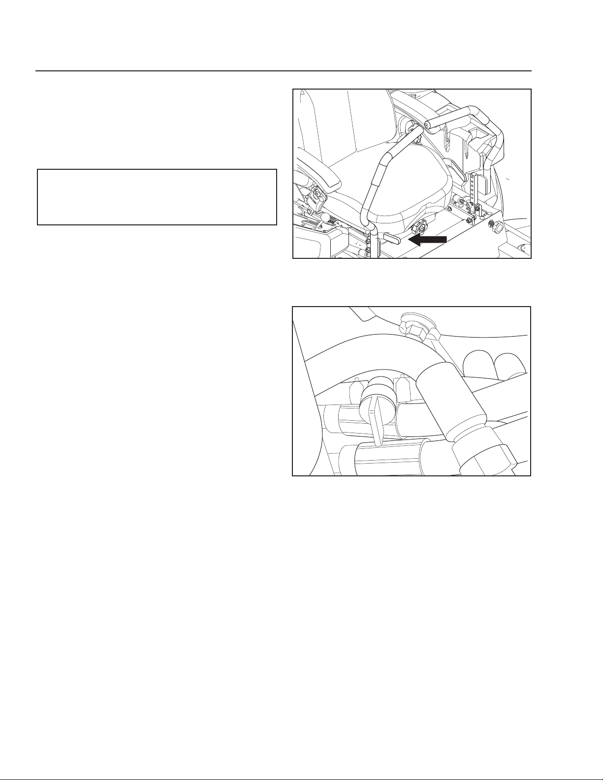
The seat can be adjusted lengthways. The lever is
located at the right side of the seat (as seen by the
driver in the seat). When making adjustments the
lever is moved to the left or upward depending on
model.
IMPORTANT INFORMATION
Seat should not be adjusted while unit is in
motion.
Fuel Shut Off Valve
The fuel shut off valve is located at the left rear of the
seat. The valve is off when the handle tab is turned
perpendicular to the fuel line.
8065-009
Lengthways adjustment
24
8065-010
Fuel shut off valve in the CLOSED position.
Page 25
CONTROLS
Fuel Tank
IMPORTANT INFORMATION
It is recommended that fuel be added to both
tanks on initial start up.
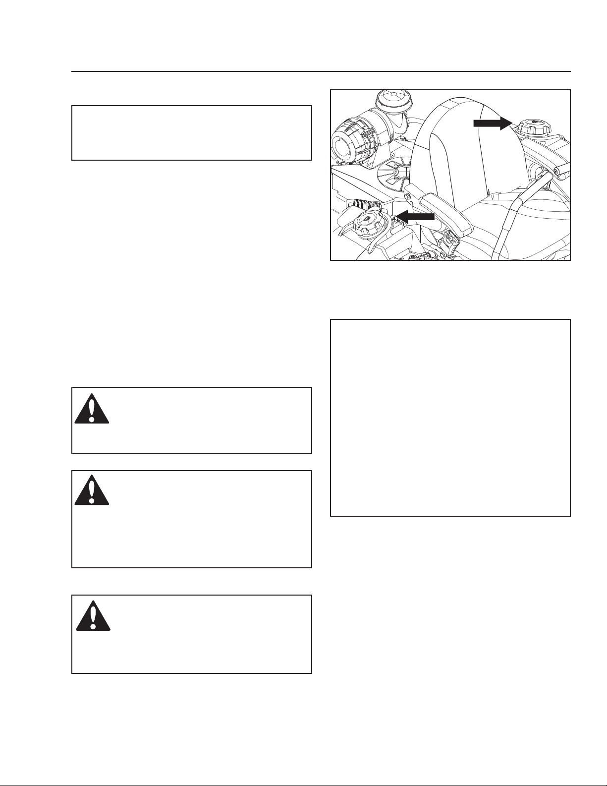
Read the safety instructions before refueling. The
machine has two fuel tanks, one on each side just
behind the seat. The capacity for each tank is 5.5
gallons (20.5 liters).
Regularly check the gas cap gasket for damage and
keep the cap properly tightened.
The engine will run on a minimum of 87-octane
unleaded gasoline (no oil mix). Environmentally
adapted alkylate gasoline can be used. See Technical
Data concerning ethanol fuel. Methanol fuel is not
allowed. Do not use E85 alcohol based fuel. Damage
to the engine and components may occur.
When operating in temperatures below 32° F. (0° C.),
use fresh, clean winter grade gasoline to help insure
good cold weather starting.
WARNING!
Gasoline is highly flammable. Observe
caution and fill the tank outdoors (see
the Safety section).
WARNING!
The engine and the exhaust system
become very hot during operation.
Risk for burns if touched.
Allow engine and exhaust system to
cool before refueling.
8065-007
Gasoline fuel tanks
IMPORTANT INFORMATION
Experience indicates that alcohol blended
fuels (called gasohol, ethanol or methanol)
can attract moisture which leads to separation
and formation of acids during storage. Acidic
gas can damage the fuel system of an engine
while in storage. To avoid engine problems,
the fuel system should be emptied before
storage of 30 days or longer. Drain the gas
tank, start the engine and let it run until the
fuel lines and carburetor are empty. Use fresh
fuel the next season. See Storage Instructions
for additional information. Never use engine
or carburetor cleaners in the fuel tank or
permanent damage may occur.
WARNING!
Fill to bottom of filler neck. Do not
overfill. Wipe off any spilled oil or fuel.
Do not store, spill or use gasoline near
an open flame.
25
Page 26

OPERATION
Read the Safety Instructions section and the
following pages if you are unfamiliar with the machine.
Training
Due to unique steering capabilities, zero turn mowers
are far more maneuverable than typical riding
mowers.
This section should be reviewed in its entirety prior to
attempting to move the mower under its own power.
When first operating the mower or until becoming
comfortable with controls, use a reduced throttle
speed and reduced ground speed. DO NOT move
control levers to the furthest forward or reverse
positions during initial operation.
First time users should become familiar with the
mower’s movement on a hard surface, such as
concrete or blacktop PRIOR to attempting to operate
on turf. Until the operator becomes comfortable with
the mower controls and zero turning capability, overly
aggressive maneuvers may damage turf.
Steering
To move forward and backward
The direction and speed of the mower’s movements
is effected by the movement of the control lever(s)
on each side of mower. The left control lever controls
the left wheel. The right control lever controls the right
wheel.
line. Pull back on control levers to the neutral position
and mower should stop moving. Pull back slightly on
control levers, this will allow mower to start moving
backwards. Push forward on control levers to the
neutral position and mower should stop moving.
To turn to the right
While moving in a forward direction, pull the right lever
back towards the neutral position while maintaining
the position of the left lever, this will slow the rotation
of the right wheel and cause the machine to turn in
that direction.
To turn to the left
While moving in a forward direction pull the left lever
back towards the neutral position while maintaining
the position of the right lever, this will slow the rotation
of the left wheel and cause the machine to turn in that
direction.
To zero turn
While moving in a forward direction, first pull both
control levers back until the mower stops or slows
dramatically.
Then by alternating one lever slightly to the forward
position and the other in the reverse position,
complete the turn.
IMPORTANT INFORMATION
When control levers are in the reverse position
they return to neutral when released. This may
cause the mower to suddenly stop.
First time users should push mower (see Moving
Machine By Hand in the Operation section) to an
open, flat area, without other people or vehicles or
obstacles nearby. To move unit under its own power,
the operator must be in the seat, start engine (see
Before Starting in the Operation section), adjust
engine speed to idle, disengage parking brake, do
not engage blades at this time, rotate control levers
inward. As long as the control levers have not been
moved forward or backwards, mower will not move.
Slowly move both control levers forward slightly. This
will allow mower to start moving forward in a straight
26
Page 27
OPERATION
Roll Bar and Safety Belt
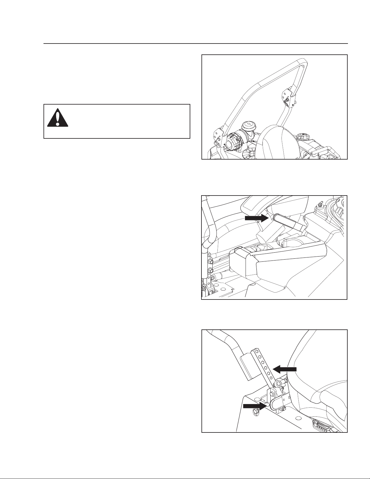
Operate the unit with the roll bar in the raised and
locked position and use the seat belt. There is no
rollover protection when the roll bar is down. If it is
necessary to lower roll bar, do not wear the seat belt.
Raise the roll bar as soon as clearance permits.
WARNING!
The seat belt must be used when the
roll bar is in upright position.
Before Starting
1. Read the sections on Safety and Controls before
starting the machine.
2. Perform the daily maintenance before starting
(see Maintenance Schedule in the Maintenance
section).
3. Check that there is sufficient fuel in the fuel tank.
4. Make sure that the parking brake is engaged.
8065-011
Roll bar in upright position
5. Adjust the seat to the desired position.
6. Place the steering controls in the neutral position.
8065-006
Activate parking brake before starting
8065-018
Place controls in neutral position
27
Page 28
OPERATION
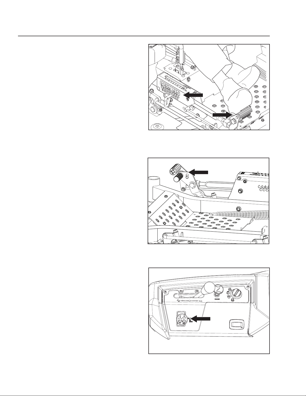
7. Push foot pedal fully forward for transport position.
Set pin at desired cutting height. (Height selection
pin is removed by rotating 180O.) Make sure that
the pin is inserted fully through the both sides of
the height panels.
The following conditions must be fulfilled before the
engine can be started:
• The blade switch for engaging the mower blades
must be depressed.
• The parking brake must be on.
• Both steering controls must be in the locked
(outer) neutral position.
Starting the Engine
1. Sit on the seat.
2. Raise the mower deck to the transport position by
setting the lift pedals fully forward.
3. Activate the parking brake.
8065-016
Set deck to selected cutting height
4. Disengage the mower blades by pressing the
blade switch downwards.
28
8065-017
Set mower deck to the transport position
8065-004
Press the control for disengaging the mower deck
Page 29
OPERATION
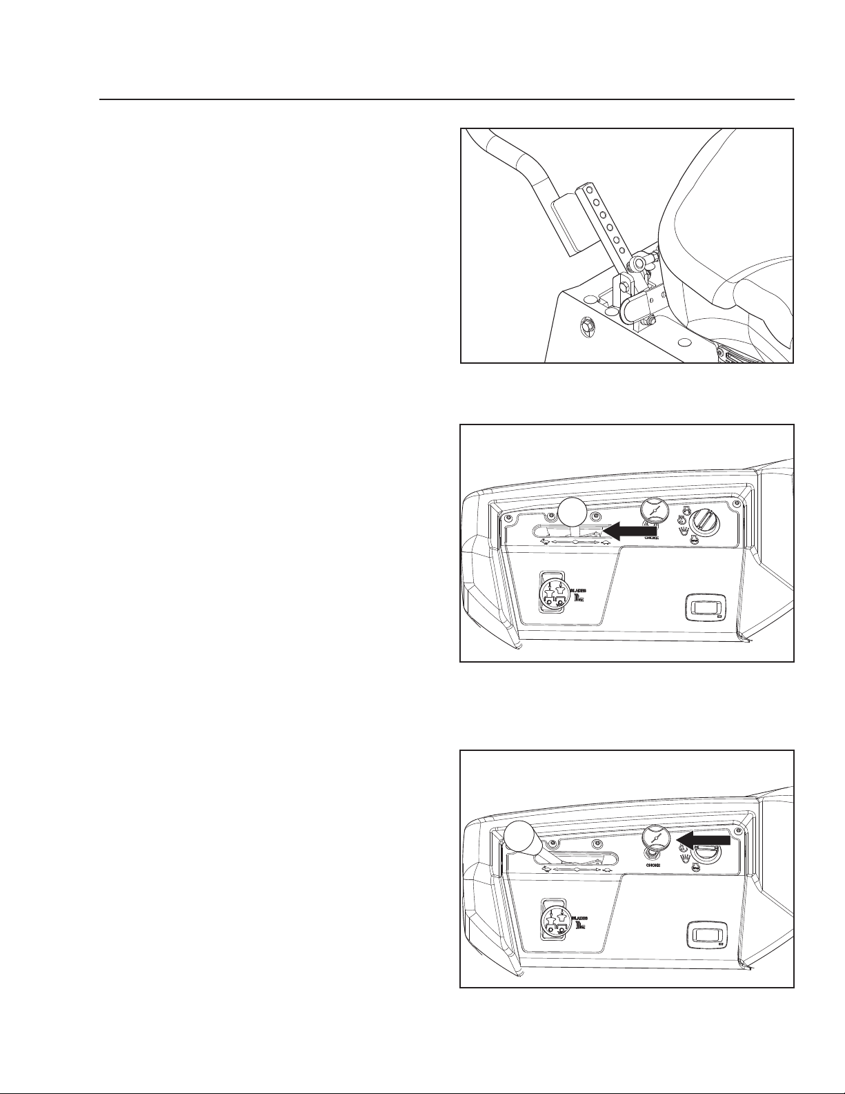
5. Move the steering controls outward to the locked
(outer) neutral position.
6. Move the throttle to the middle position.
8065-018
Place controls in neutral position
7. If the engine is cold, the choke control should be
pulled up.
8065-019
Set the throttle
8065-015
Set the choke control
29
Page 30
OPERATION
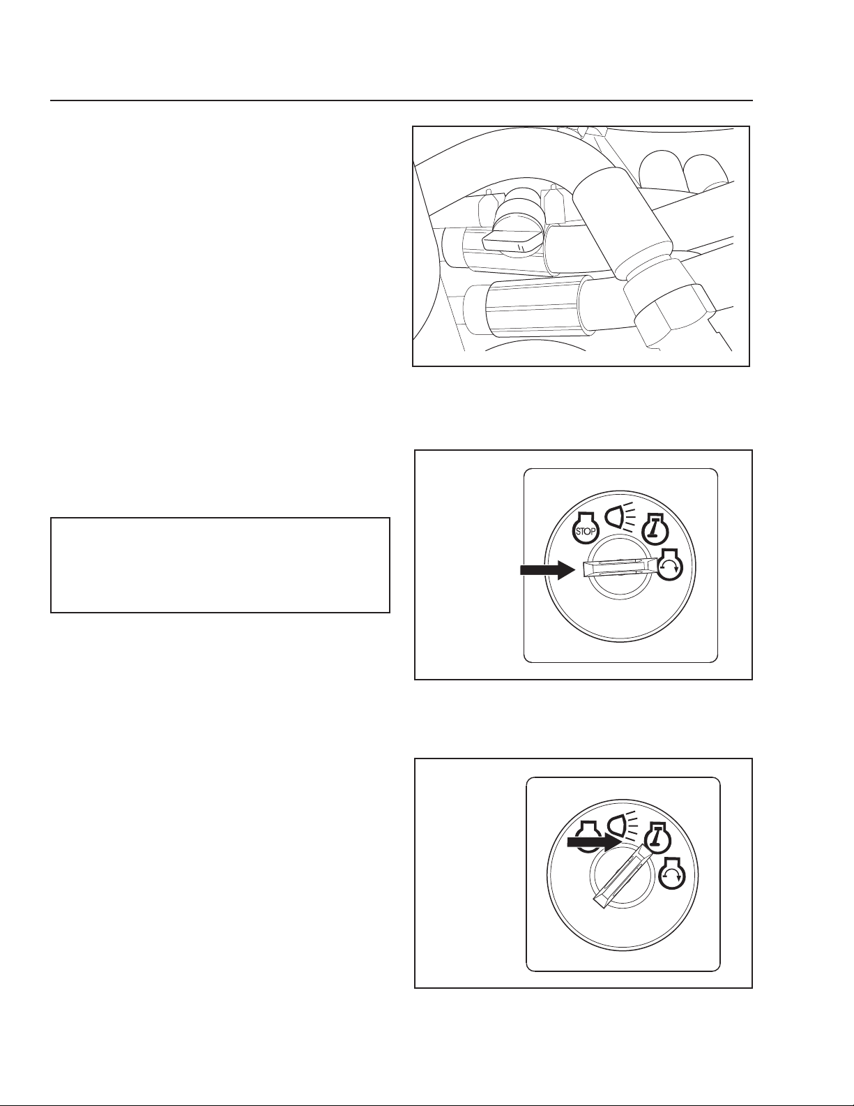
8. Open the fuel tank valve.
9. Press in and turn the ignition key to the start
position.
8065-013
Fuel valve in the OPEN position
IMPORTANT INFORMATION
Do not run the starter for more than 5 seconds
each time. If the engine does not start, wait
about 10 seconds before retrying.
10. When the engine starts, immediately release the
ignition key back to the run position. Push the
choke control in gradually when the engine has
started.
8050-780
Turn to the start position
30
8050-781
Return to run position
Page 31
OPERATION
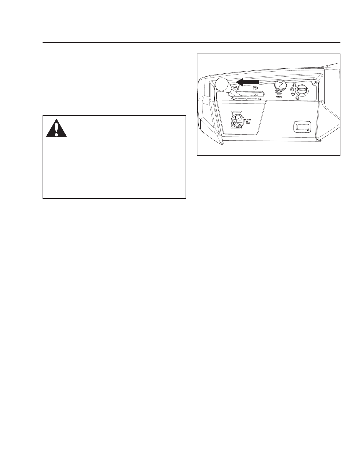
11. Set the engine speed with the throttle. Allow the
engine to run at a moderate speed, approximately
mid throttle, for 3-5 minutes before loading it too
heavily. USE FULL THROTTLE WHEN MOWING
(no choke).
WARNING!
Engine exhaust and certain vehicle
components contain or emit chemicals
considered to cause cancer, birth
defects or other reproductive system
damage. The engine exhaust contains
carbon monoxide, which is an
odorless, colorless, poisonous gas.
Do not use the machine in enclosed
spaces.
8065-015
Set the engine speed
31
Page 32
OPERATION
Weak Battery
WARNING!
Lead-acid batteries generate
explosive gases. Keep sparks, flame
and smoking materials away from
batteries. Always wear eye protection
when around batteries.
IMPORTANT INFORMATION
The mower is equipped with a 12-volt negative
grounded system. The other vehicle must also
be a 12-volt negative grounded system. Do not
use the mower to start other vehicles.
If the battery is too weak to start the engine, it should
be recharged. (See Battery in the Maintenance
section.)
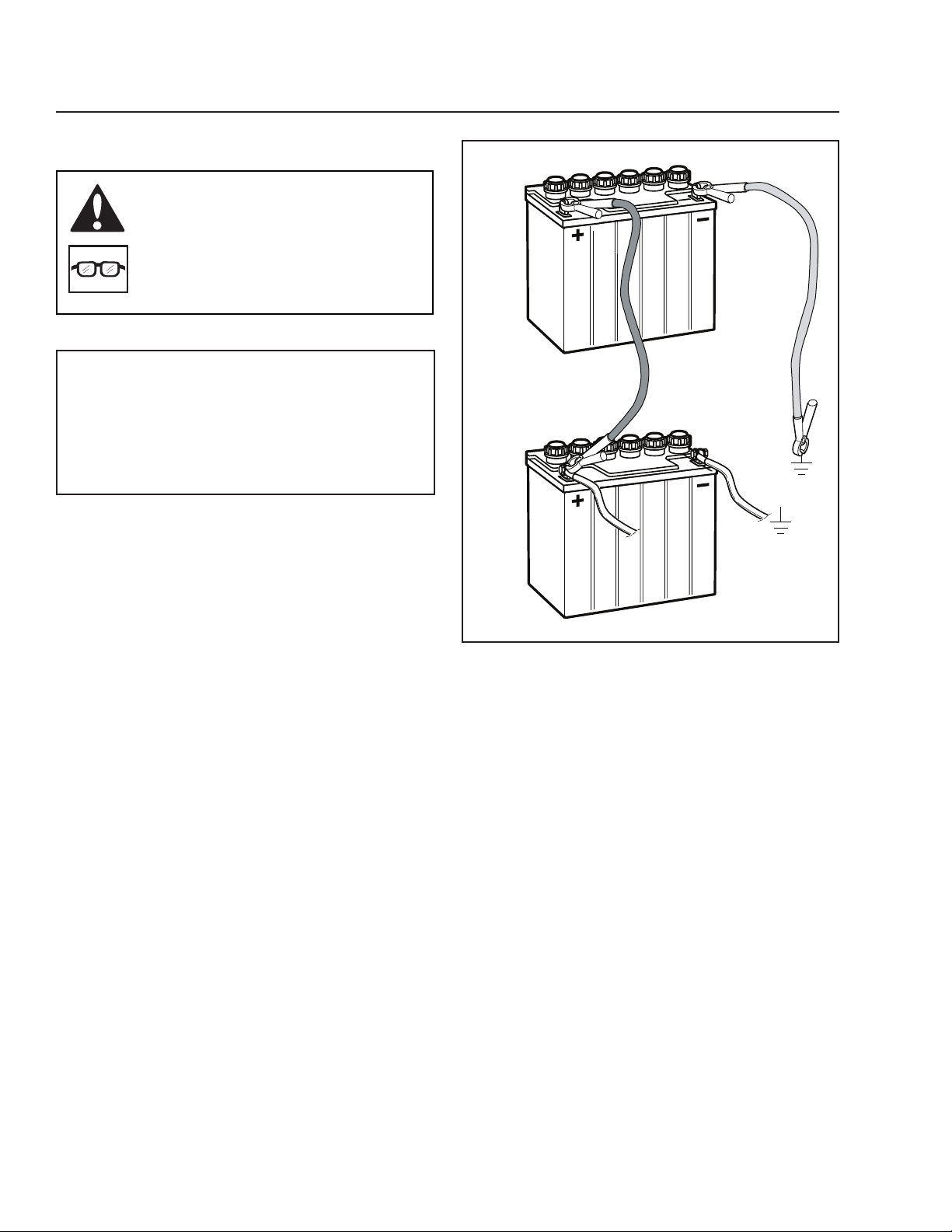
Jumper Cables Use
1. Connect each end of the RED cable to the
POSITIVE (+) terminal on each battery, taking
care not to short against chassis.
2. Connect one end of the BLACK cable to the
NEGATIVE (-) terminal of the fully charged battery.
3. Connect the other end of the BLACK cable to a
good CHASSIS GROUND on the mower with the
discharged battery, away from the fuel tank and
battery.
To remove cables, reverse order
4. Remove BLACK cable first from chassis and then
from the fully charged battery.
5. Remove RED cable last from both batteries.
8011-642
Jumper cable connection
32
Page 33
OPERATION
Running
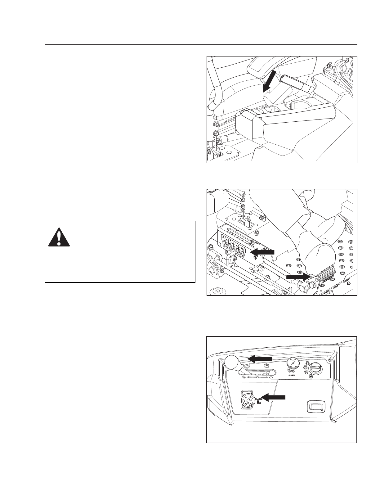
1. Release the parking brake by moving the lever
downward.
NOTE: The mower is equipped with an operator
presence system. When the engine is running,
any attempt by the operator to leave the seat
without first setting the parking brake will shut off
the engine.
2. Move the steering controls inwards, out of the
neutral position (N).
3. Release deck height control by applying equal
pressure to both pedals. Push pedals again to
lower deck to selected setting.
8065-006
Release the parking brake
WARNING!
Make sure that no one is near mower
when engaging blade switch.
Make sure the work area is free from
objects that could be thrown by the
rotating blades.
4. Move throttle control to full throttle.
5. Engage the mower deck by pulling out the blade
switch.
8065-016
Set deck to selected cutting height
Engage the mower deck and move throttle to full.
8065-015
33
Page 34
OPERATION
Operating on Hills
Read the Safety Instructions Driving on Slopes in the
Safety Instructions.
WARNING!
Do not drive up or down hills with
slopes greater than 10 degrees. Do not
drive across slopes.
• The slowest speed possible should be used
before starting up or down hills.
• Avoid stopping or changing speed on hills.
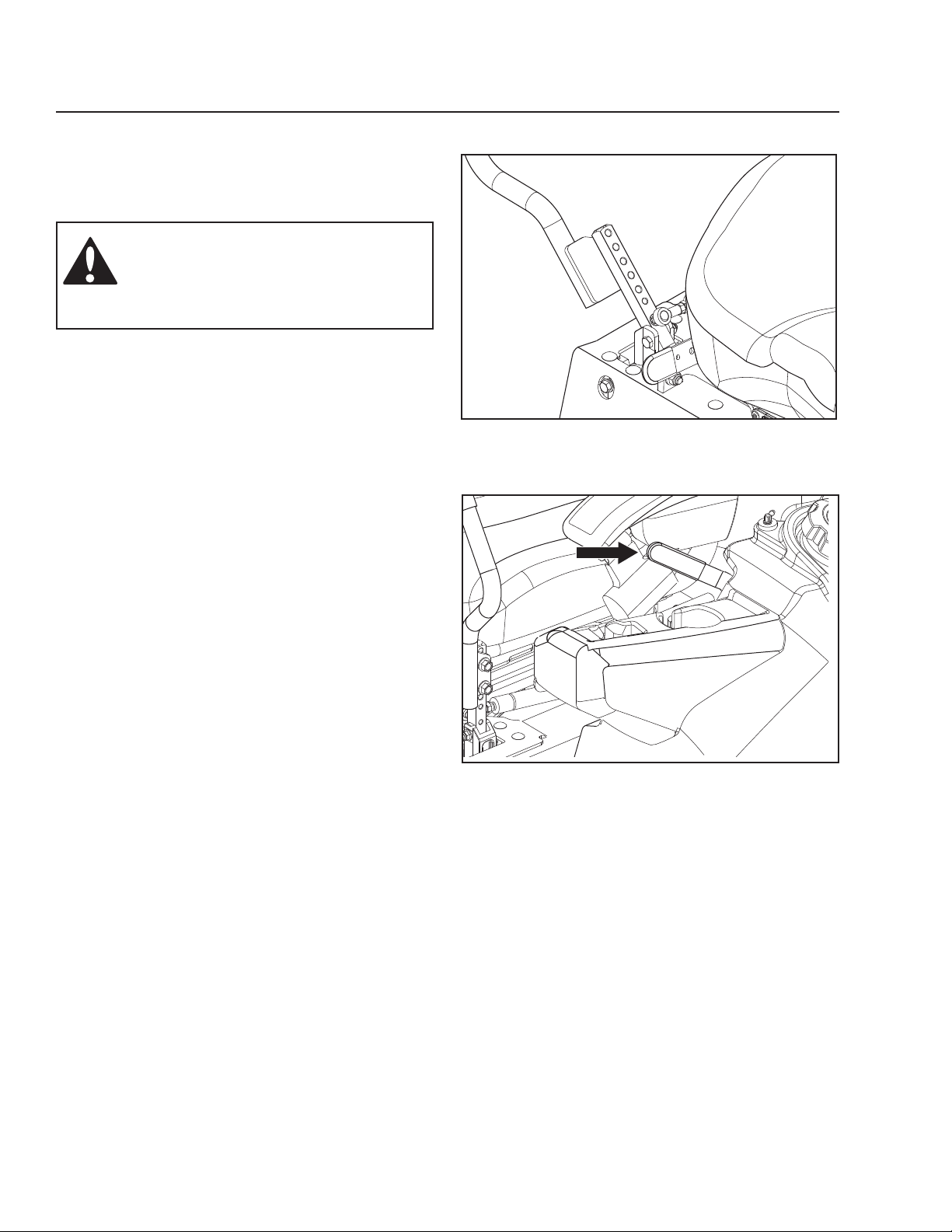
• If stopping is absolutely necessary, pull drive
levers into the neutral position and push to the
outside of the unit and engage the parking brake.
• To restart movement, release the parking brake.
• Pull the control levers back to the center of the
mower and press forward to regain forward
motion.
• Make all turns slowly.
8065-018
Place controls in neutral position
34
8065-006
Release the parking brake
Page 35
OPERATION
Mowing Tips
• Observe and flag rocks and other fixed objects to
avoid collisions.
• Begin with a high cutting height and reduce it
until the desired mowing result is attained. The
average lawn should be cut to 2½" (64 mm)
during the cool season and over 3" (76 mm)
during the hot months. For healthier and better
looking lawns, mow often after moderate growth.
• For best cutting performance, grass over 6" (15
cm) in height should be mowed twice. Make the
first cut relatively high; the second to the desired
height.
• The mowing result will be best with a high engine
speed (the blades rotate rapidly) and low speed
(the rider moves slowly). If the grass is not
too long and dense, the driving speed can be
increased without negatively affecting the mowing
result.
• The finest lawns are obtained by mowing often.
The lawn becomes more even and the grass
clippings more evenly distributed over the mown
area. The total time taken is not increased as a
higher operating speed can be used without poor
mowing results.
• Avoid mowing wet lawns. The mowing result is
poorer because the wheels sink into the soft lawn,
clumps build, and the grass clippings fasten
under the cowling.
• Hose the mower deck underside with water after
each use. When cleaning, the mower deck shall
be raised into the transport position. Make sure
the mower is cooled and the engine is off.
• Use compressed air to clean top surface of the
deck. Avoid flooding water on top surface, engine
and electrical components.
• When the mulching kit is used, it is important that
the mowing interval is frequent and that the deck
is cleaned more often.
WARNING!
Clear the lawn of stones and other
objects that can be thrown out by the
blades.
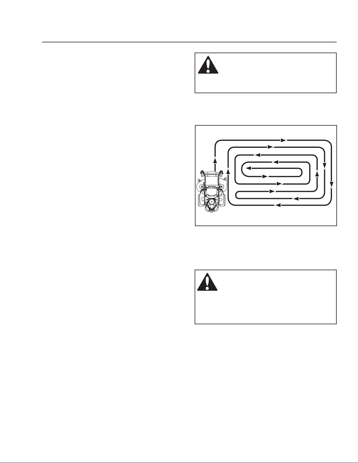
8011-603b
Mowing pattern
WARNING!
Never drive the rider on terrain that
slopes more than 10 degrees. Mow
slopes up and down, never side
to side. Avoid sudden directional
changes.
35
Page 36
OPERATION
Stopping the Engine
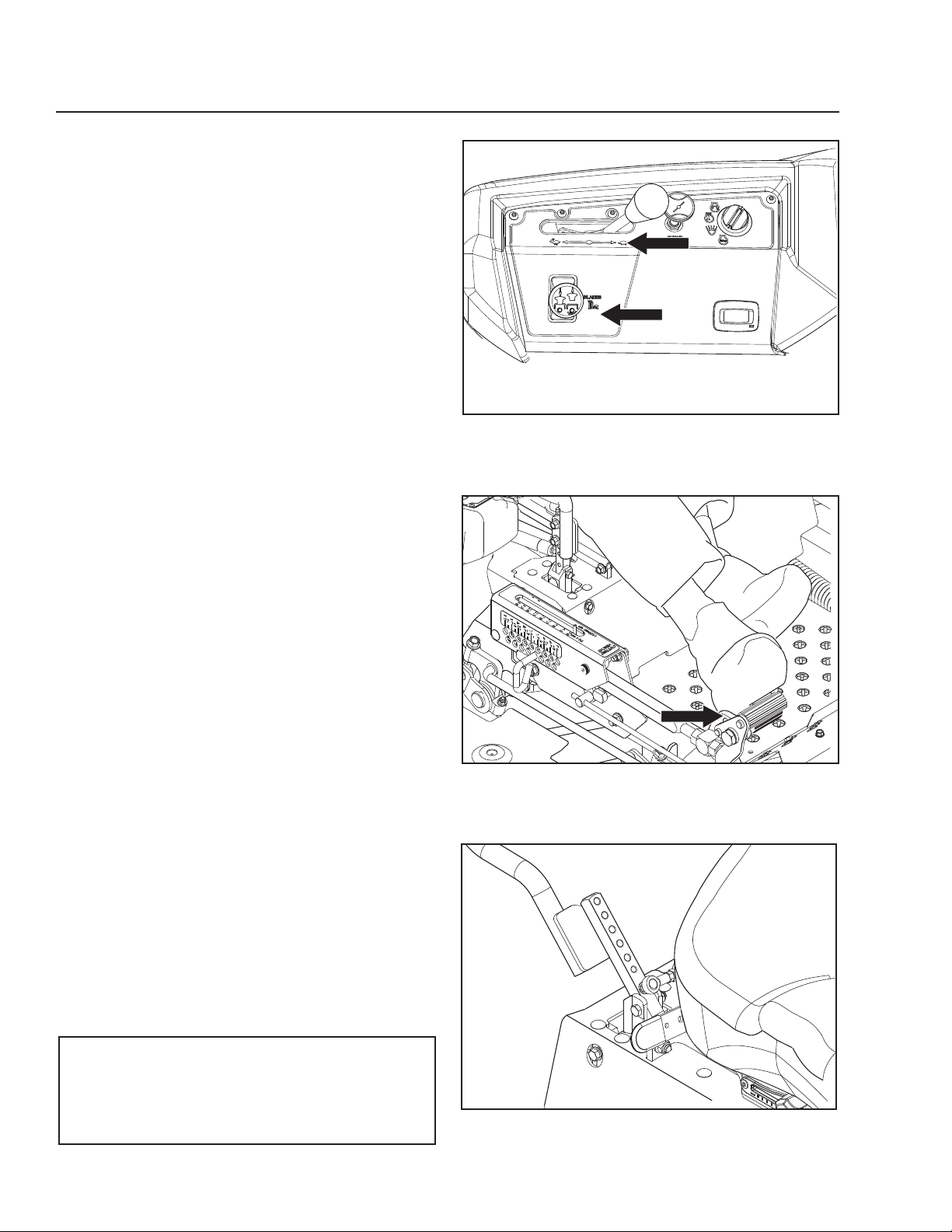
1. Move the throttle to the minimum position (tortoise
symbol).pressing the blade switch.
2. Move the steering controls outward to the neutral
position.
3. Disengage the mower deck by depressing the
blade switch.
4. Raise the mower deck by pressing the foot pedal
forward to the transport position.
5. When the machine is standing still, activate the
parking brake by pulling the lever upward.
8065-004
Disengage the mower deck and move throttle to minimum
6. Turn the ignition key to the stop position. If the
engine has been worked hard, allow it to idle
a minute in order to attain a normal operating
temperature before stopping. To prevent fouling
the spark plugs, avoid idling the engine for longer
periods.
7. Remove key. To prevent unauthorized use, always
remove key when leaving the mower.
IMPORTANT INFORMATION
Leaving the ignition switch in any other
position than OFF will cause the battery to be
discharged.
36
8065-016
Raise deck to transport position
8065-018
Place controls in neutral position to stop
Page 37
OPERATION
Moving Machine By Hand
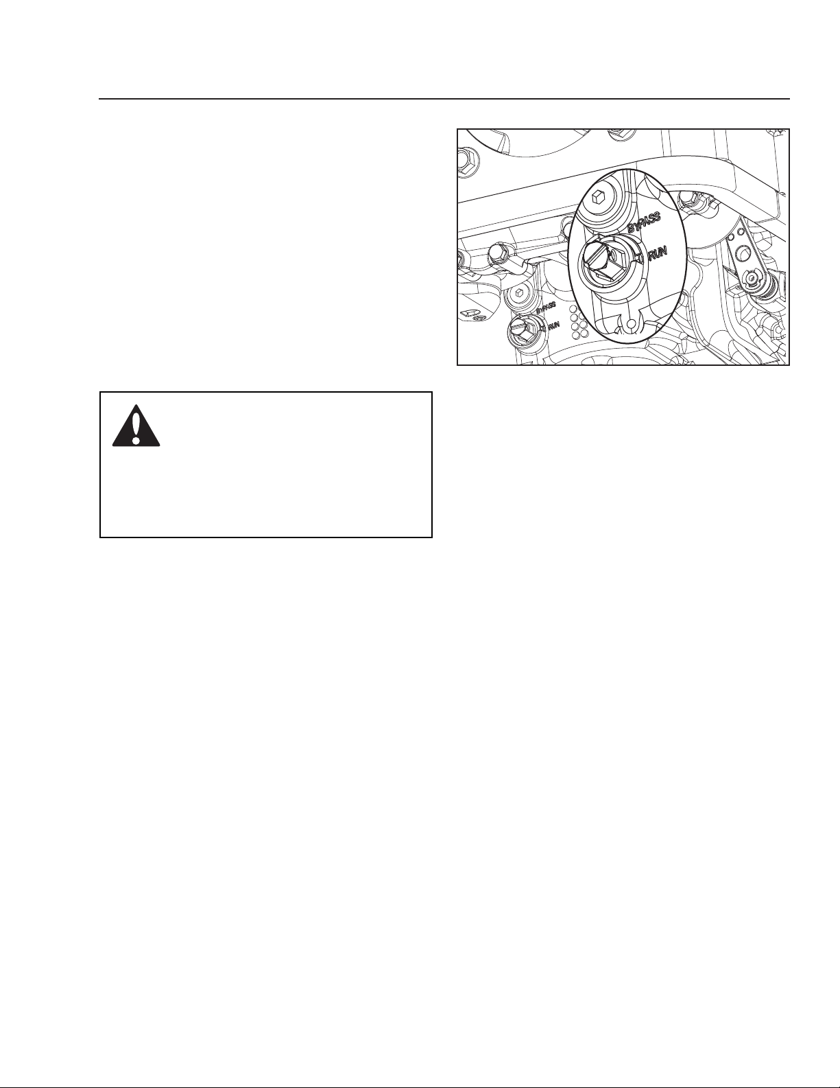
Bypass Valves
Bypass valves are used to release the system so the
machine may be moved by hand when not running.
ZT-5400
Access to the bypass valves is from the lower rear
of the unit. The valves are located on the front, inner
sides of the transaxles.
Set the deck to the lowest position when accessing
the bypass valves.
To disengage each pump, turn the slot on the bypass
valve 45O clockwise from the DRIVE position to the
BYPASS position.
WARNING!
No adjustments or maintenance
should be carried out unless:
• the engine stopped
• the ignition key removed
• the parking brake activated
8050-231
Right side, ZT-5400 bypass valve
37
Page 38

MAINTENANCE
MAINTENANCE
Check the parking brake
Check the engine’s oil level (every refueling)
Check the safety system
Check for fuel and oil leakages
Check/clean the engine’s cooling air intake
Check the mower deck
Check for loose hardware (screws, nuts)
Clean under the mower deck
Start the engine and blades, listen for unusual sounds
Check for damage
Thoroughly clean around the engine
Clean around belts, belt pulleys
Check the tire pressures
Check battery connections
Sharpen3)/ Replace mower blades
Clean the engine’s cooling air intake
Clean the air cleaner’s pre-filter 2) (foam)
Clean the air cleaner’s filter cartridge 2) (paper filter)
Check/adjust the parking brake
Inspect muffler/spark arrester
2)
Daily At least
once
each
Before After 50 250 500
year
Maintenance interval
in hours
●
■
●
♦
■
●
●
● ● ● ●
♦
♦ ♦ ♦ ♦
♦ ♦ ♦ ♦
♦ ♦ ♦ ♦
● ● ● ●
● ● ● ●
● ● ● ●
■ ■ ■ ■
■ ■
■ ■
● ● ● ●
♦ ♦ ♦ ♦
1)
First change after 8-10 hours. When operating with a heavy load or at high ambient temperatures, replace every 50 hours.
conditions, cleaning and replacement are required more often.
3)
Performed by authorized service workshop.
● = Described in this manual
♦ = Not described in this manual
■ = Refer to the engine manufacturer's manual
38
2)
In dusty
Page 39
MAINTENANCE
MAINTENANCE
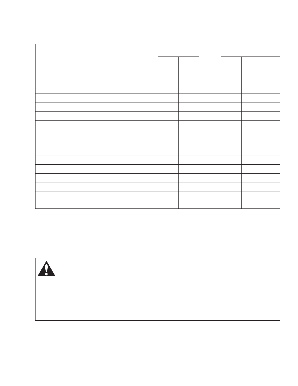
Check/adjust throttle cable
Check the condition of belts, belt pulleys
Change the engine oil
Replace the engine oil filter
Clean/replace the spark plugs
Replace the fuel filter
Replace air filter 2) (paper filter)
Check the caster wheels (every 200 hours)
Replace the air cleaner’s pre-filter 2) (foam)
Check the hydraulic oil in the oil tank
Change the hydraulic oil (every 500 hours)
Replace the hydraulic oil filter (every 500 hours)
Dismantle and inspect starter 3) (every 500 hours)
Check/adjust the mower deck
Check the engine valve clearance
Perform the 500-hour service
1)
3)
3)
Daily At least
once
each
Before After 50 250 500
year
Maintenance interval
in hours
■
● ●
■ ■
■ ■
● ■
● ●
■ ■
● ●
■
●
● ●
● ●
♦
● ●
♦ ♦
♦ ♦
1)
First change after 5-8 hours. When operating with a heavy load or at high ambient temperatures, replace every 50 hours.
conditions, cleaning and replacement are required more often.
3)
Performed by authorized service workshop.
● = Described in this manual
♦ = Not described in this manual
■ = Refer to the engine manufacturer's manual
WARNING!
Before performing any service or adjustment checklist:
• Engage the parking brake.
• Place the Blade-switch in the disengaged position.
• Turn the ignition switch to OFF position and remove the key.
• Make sure the blades and all moving parts have completely stopped.
• Disconnect the spark plug wire from all spark plugs and place the wire where it
cannot come in contact with the plug.
2)
In dusty
39
Page 40
MAINTENANCE
Battery
The mower is equipped with a maintenance free
battery and does not need servicing. However,
periodic charging of the battery with an automotive
type battery charger will extend its life.
• Keep battery and terminals clean.
• Keep battery bolts tight.
• See chart for charging times.
WARNING!
Always wear eye protection when
around batteries.
Battery Removal
Corrosion and dirt on the battery and terminals can
cause the battery to “leak” power.
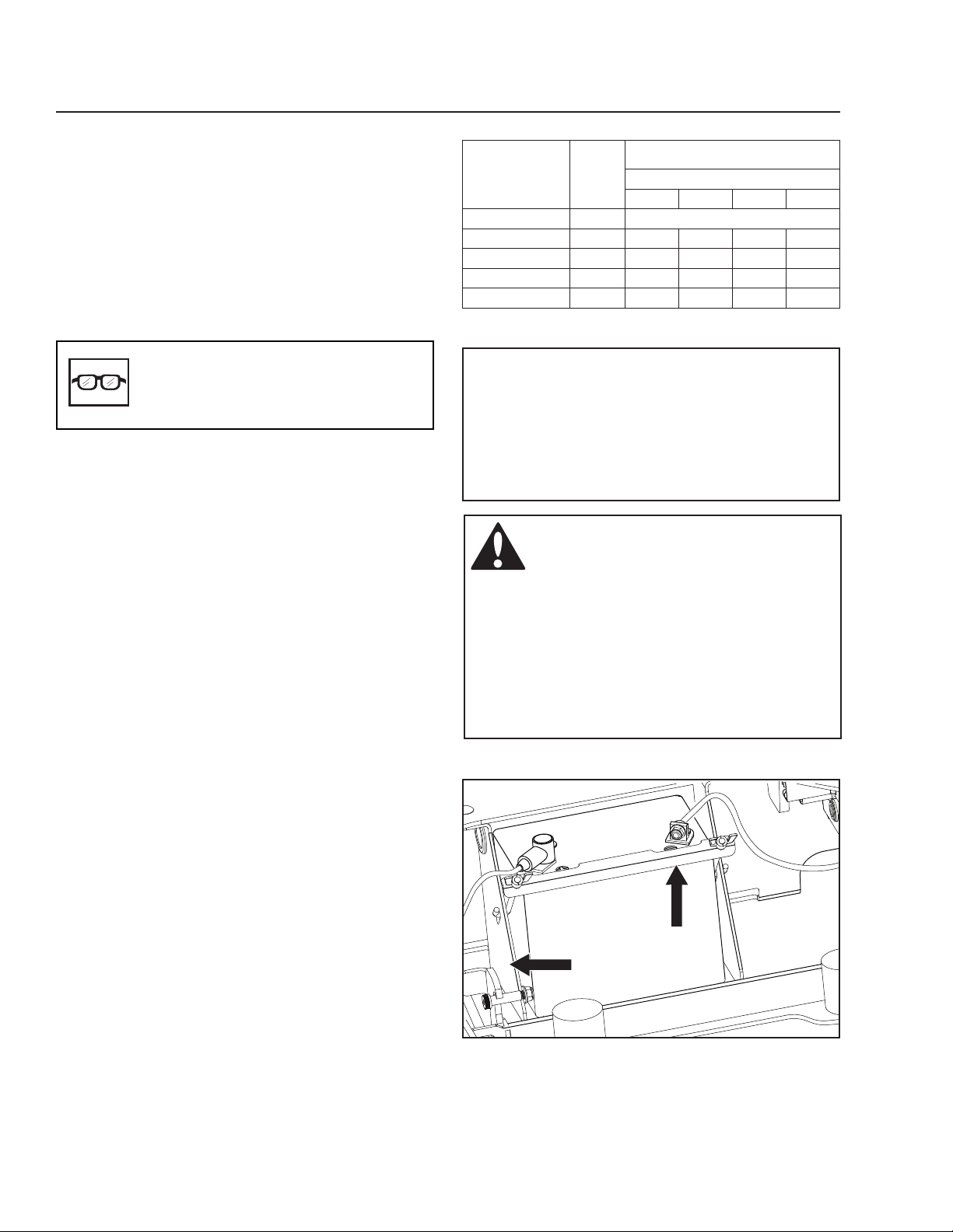
1. Lift the seat and rotate fully forward until
supported by the seat rod.
2. Loosen the two wingnuts attached to the side “J”
bolts just enough that the battery mount bracket
slides down off the battery.
3. Using two ½" wrenches disconnect BLACK
battery cable then RED battery cable.
4. Carefully remove the battery from the mower.
For cleaning
5. Rinse the battery with plain water and dry.
6. Clean terminals and battery cable ends with wire
brush until shiny.
STANDARD
BATTERY
12.6V 100%
12.4V 75% 20 min. 35 min. 48 min. 90 min.
12.2V 50% 45 min. 75 min. 95 min. 180 min.
12.0V 25% 65 min. 115 min. 145 min. 280 min.
11.8V 0% 85 min. 150 min. 195 min. 370 min.
STAT E
OF
CHARGE
*Charging time depends on battery capacity,
condition, age, temperature and efficiency of charger
APPROXIMATE BATTERY CHARGING TIME*
TO FULL CHARGE AT 80OF / 27OC
Maximum Rate at:
50 Amps 30 Amps 20 Amps 10 Amps
- FULL CHARGE -
IMPORTANT INFORMATION
Do not attempt to open or remove caps or
covers. Adding or checking level of electrolyte
is not necessary.
Always use two wrenches for the terminal
screws.
WARNING!
Do not short battery terminals by
allowing a wrench or any other object
to contact both terminals at the same
time. Before connecting battery,
remove metal bracelets, wristwatch
bands, rings, etc.
Positive terminal must be connected
first to prevent sparks from accidental
grounding.
For replacing
7. Install new battery with terminals in the same
position as the old battery.
8. Connect RED battery cable first to positive (+)
battery terminal.
9. Connect BLACK grounding cable to negative (-)
battery terminal.
10. Slide mount bracket back up over battery and
retighten wingnuts.
11. Lower seat.
40
1
2
8065-020
1. Mount bracket
2. Battery bracket
Battery cleaning and installation
Page 41
MAINTENANCE
Safety System
This machine is equipped with a safety system
that prevents starting or driving under the following
conditions.
The engine can only be started when:
1. The mower deck is disengaged.
2. The steering controls are in the outer, locked
neutral position.
3. The parking brake is on.
Make daily inspections to ensure that the safety
system works by attempting to start the engine
when one of the conditions is not met. Change the
conditions and try again.
If the machine starts when one of these conditions
is not met, turn the machine off and repair the safety
system before using the machine again.
Make sure the engine stops when the park brake
is not engaged and the operator leaves the seated
position.
Check that the engine stops if the mower blades are
engaged and the driver temporarily moves off the
driver's seat.
8065-021
Conditions for starting
IMPORTANT INFORMATION
To be able to drive, the driver must sit in the
seat and release the parking brake before
the steering controls can be moved into the
neutral position, otherwise the engine will
stop.
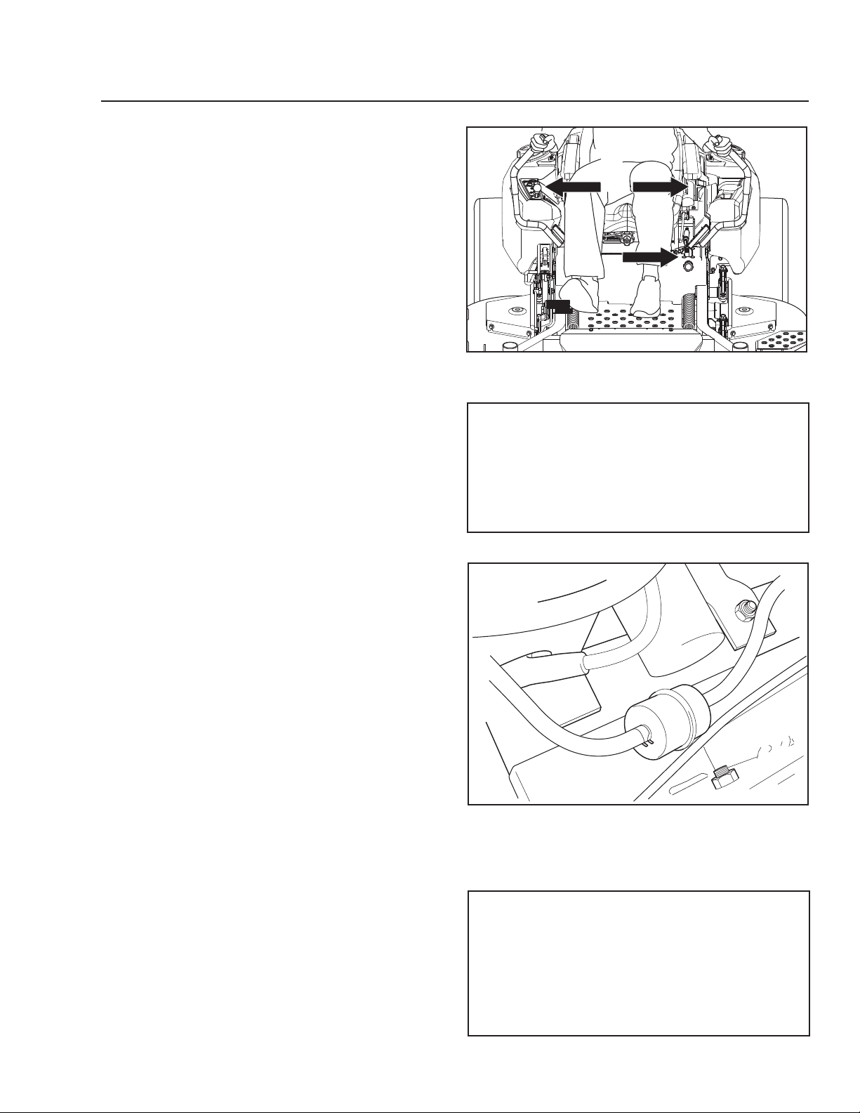
Fuel Filter
Replace the line-mounted fuel filter every 100 hours
(once per season) or more often if it becomes
clogged.
1. Move the hose clamps away from the filter. Use
flat-nosed pliers.
2. Pull the filter loose from the hose ends.
3. Push the new filter into the hose ends. Position
the filter with the FLOW arrow pointing toward the
fuel pump. If necessary, a soap solution can be
applied to the filter ends to ease mounting.
4. Move the hose clamps back toward the filter.
Tire Pressures
Fill tire pressures to 15 psi / 103 kPa / 1 bar.
8065-026
Fuel filter
IMPORTANT INFORMATION
DO NOT add any type of tire liner or foam
fill material to the drive tires. Excessive
loads created by foam filled tires will cause
premature failures.
Only use O.E.M. specified tires.
41
Page 42
MAINTENANCE
Parking Brake
Visually check that no damage is found on the lever,
links, or switch belonging to the parking brake.
Perform a standstill test and check that there is
sufficient braking action.
WARNING!
Faulty adjustment result in reduced
braking ability and can cause an
accident.
IMPORTANT INFORMATION
The machine must be standing still when
applying the parking brake.
8065-006
Parking brake
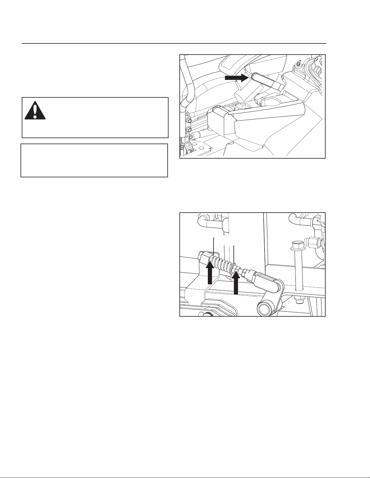
Parking Brake Adjustments
1. Using a jack stand, raise the rear of the mower up
off the ground. Make sure the machine is securely
supported.
2. Remove the rear tire assemblies.
3. Release the park brake.
4. Measure the distance from the swivel to the
washer. (See Illustration). The measurement
should be 1¾" on both the right and left side
brake linkage assemblies.
1¾"
1
2
8065-051
1. Swivel
2. Washer
Parking brake adjustment
42
Page 43
MAINTENANCE
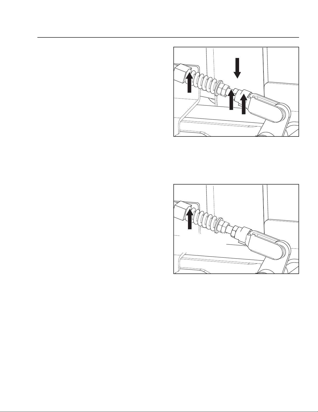
5. If adjustments are needed, loosen B jam nut
and turn A jam nut until the correct distance is
achieved. Retighten B jam nuts against A jam
nuts.
D
Parking brake adjustment
B
A
C
8065-052
6. Engage the park brake. Measure the distance
between the D brake bolt and the brake swivel.
The distance should be 1/8"-¼".
7. If adjustments are needed, loosen C jam nut.
Turn the brake bolt until the distance is correct.
Retighten C jam nuts.
1
/8"-¼" gap with park
brake engaged
Measure gap
8065-052
43
Page 44
MAINTENANCE
Deck Belt
Deck Belt Removal
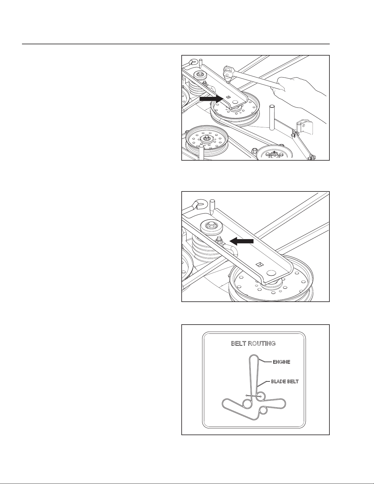
Park on a level surface. Apply park brake. Lower the
deck into the lowest cutting position.
1. Remove foot plate and belt shields.
2. Remove any dirt or grass that may have
accumulated around the cutter housings and
entire deck surface.
3. With a ½" breaker bar and using the square
opening in the idler arm, shift the arm counter
clockwise to relieve the tension on the belt.
4. Carefully roll the belt over the top of the cutter
housing pulleys.
5. Remove the belt guide hardware with a ½" wrench
and set belt guide aside.
6. Remove the belt from around the electric clutch
on the engine shaft.
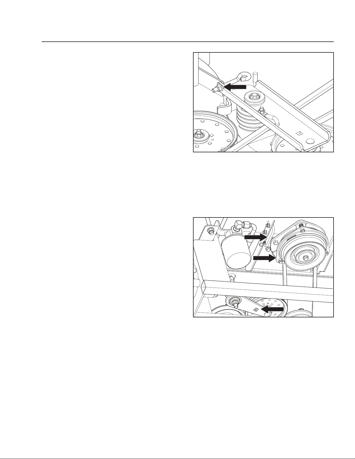
8065-040
Release the belt tension
Deck Belt Installation
NOTE: For ease in installing the deck belt, refer to the
routing decal on the cutting deck.
1. Place the belt around all the pulleys except the
center spindle pulley.
2. With a ½" breaker bar, shift the idler arm counter
clockwise. When there is enough slack, slip the
belt onto the center spindle pulley.
3. Reinstall the belt guide removed in Step 5 above.
4. Double check belt routing to make sure it matches
the routing decal, and that the belt does not have
any twist. Correct if needed.
44
8065-046
Remove belt guide
8065-047
Refer to belt routing decal
Page 45
MAINTENANCE
5. Adjust belt tension by turning the eyebolt until
there is approximately 7/8" -1" of threads showing
outside the nut.
6. Belt tension should be set to 60-70 lbs.
7. Replace belt shields on both mandrel housings
and secure with fasteners.
Pump Belt
The belts are not adjustable. Replace belts if they
begin to slip from wear.
Replacing Pump Belt
Park the mower on a level surface. Engage the
parking brake.
Belt Removal
1. Remove the deck belt (see Deck Belt Removal in
this section of the manual).
2. Remove clutch stop to access the belt.
3. Disconnect clutch wire.
4. With a ½" breaker bar and using the square
opening in the idler arm, shift the arm to create
slack in the belt.
5. Remove belt from the engine and pump pulleys.
Belt Installation
1. Wrap the belt around the engine pulley.
2. Wrap the belt around the left pump pulley.
3. Route the belt around the inside of the idler pulley.
4. With a ½" breaker bar and using the square
opening in the idler arm, shift the arm to create
slack in the belt.
While holding the idler back with the breaker bar,
wrap the belt around the right pump pulley.
5. Replace and secure clutch stop.
6. Reinstall the deck belt. (See Deck Belt
Installation in this section of the manual).
8065-054
Adjust belt tension
3
1
2
8065-041
1. Electric clutch
2. Idler release placement
3. Clutch stop
Pump belt removal
V-belts
Check every 100 hours of operation. Check for severe
cracking and large nicks.
NOTE: The belt will show some small cracks in normal
operation.
45
Page 46
MAINTENANCE
Cutting Blades
To attain the best mowing effect, it is important that
blades are well sharpened and not damaged.
Replace blades that have been bent or cracked when
hitting obstacles.
Let the service workshop decide whether a blade
with large nicks can be repaired/ground or must be
replaced. Balance the blades after sharpening.
Check the blade mounts.
Blade Replacement
IMPORTANT INFORMATION
The sharpening of blades should be carried
out by an authorized service workshop.
WARNING!
Blades are sharp. Protect your hands
with gloves and/or wrap blades with
a heavy cloth when handling.
1. Remove blade bolt by turning counterclockwise.
2. Install new or re-sharpened blade with stamped
GRASS SIDE facing towards ground/grass (down)
or THIS SIDE UP facing deck and cutter housing.
3. Install and tighten blade bolt securely.
4. Torque blade bolt to 90 ft-lbs (122 Nm).
IMPORTANT INFORMATION
Special blade bolt is heat treated.
Replace with a Husqvarna bolt if required.
Do not use lower grade hardware than
specified.
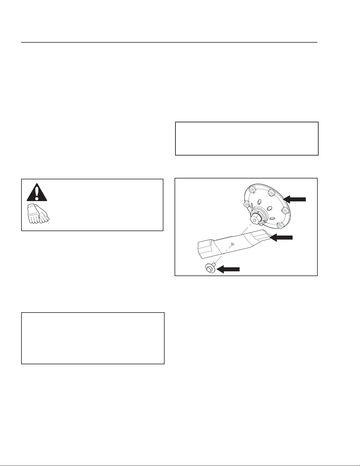
3
1
2
8065-028
1. Blade
2. Blade bolt (special)
3. Cutter housing
Blade attachment
46
Page 47
Adjusting the Mower Deck
MAINTENANCE
Leveling Deck
Adjust the deck while the mower is on a level
surface. Make sure the tires are inflated to the correct
pressure. See Tire Pressures in Maintenance section.
If tires are under or over inflated, the deck cannot be
properly adjusted. Faulty mower deck adjustments will
cause an uneven mowing result.
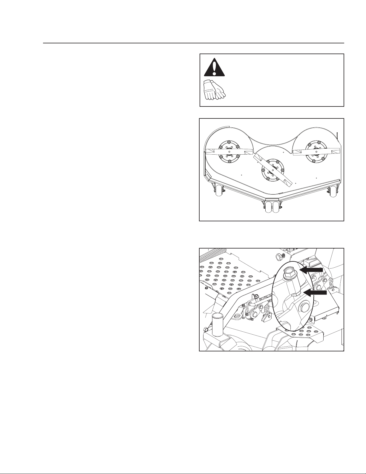
Four bolts control the height and pitch of the mower
deck. The deck should be adjusted slightly higher in
the rear.
NOTE: To insure accuracy of leveling procedure,
mower deck drive belt must be installed prior to
leveling the deck.
1. Wear heavy gloves. Turn each outer blade tip to
align the deck in a side-to-side manner.
2. Measure from the floor surface up to the bottom
of the blade tip on the discharge side of the
mower deck. Retain this measurement. Move to
the opposite side; check that measurement is
the same. If adjustment is required, loosen the
locknut and adjust bolt up until both side-to-side
measurements are equal. Retain measurement.
3. Turn both outer blades to align with the deck in
front-to-rear manner. Reposition rear mounting
bolts up or down until rear blade tips are
positioned 1/8" to 3/8" higher in the rear than the
front blade tips.
4. Confirm measurements once again. Blade tip
height should be equal in a side-to-side manner.
In the rear, blade tips should be 1/8" to 3/8" higher
than the front measurement. In the front, blade
tips should be equal from side-to-side.
NOTE: This will place the mower deck in a standard
measurement position. Additional adjustment may be
required to achieve desired cut for the type of grass
being mowed or conditions.
WARNING!
Blades are sharp. Protect your hands
with gloves and/or wrap blades with
a heavy cloth when handling.
8065-102
Set blades to begin leveling
1
2
1. Adjustment bolt
2. Locknut
Leveling the mower deck
8065-037
47
Page 48
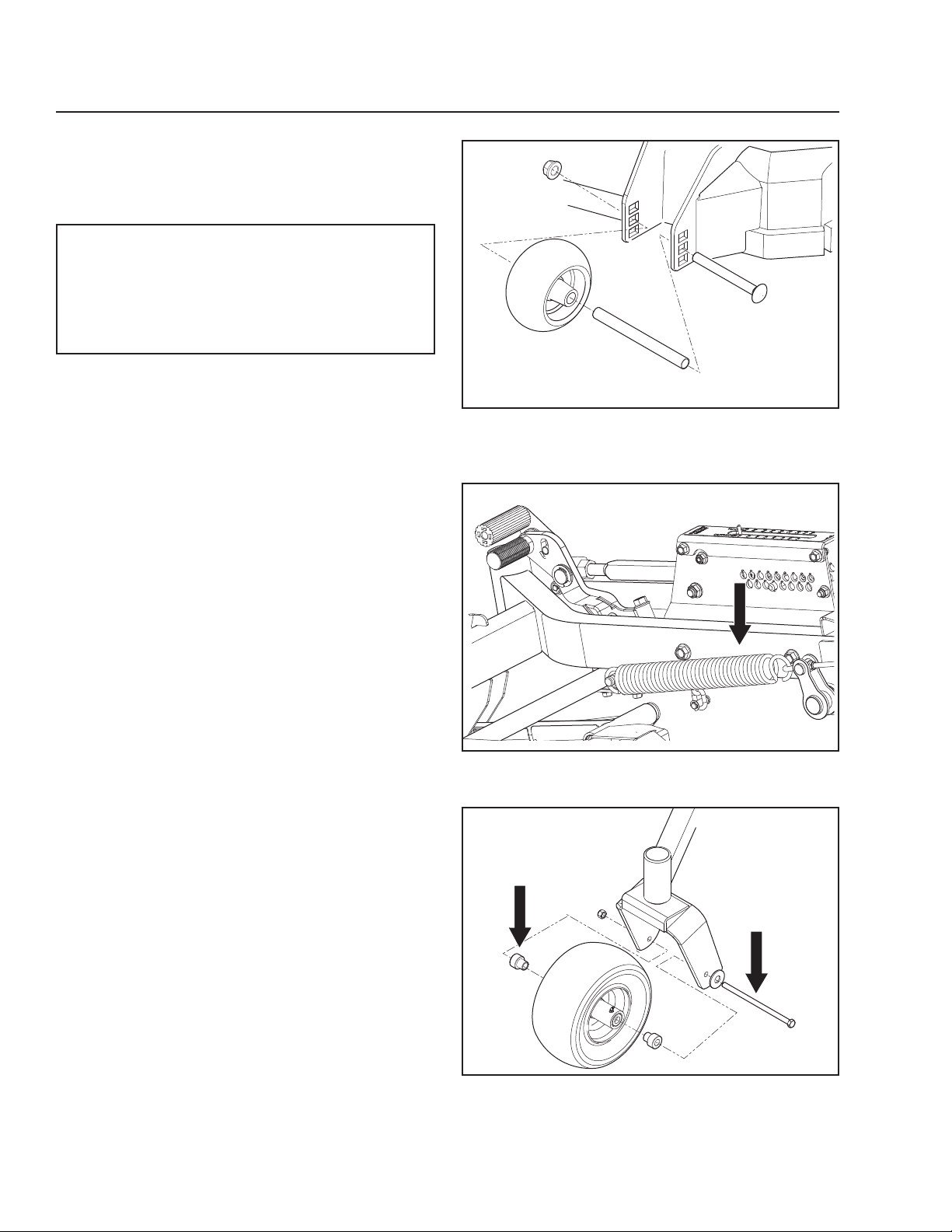
MAINTENANCE
Anti-scalp Rollers
Anti-scalp rollers keep the deck in the proper position
to help prevent scalping in most terrain conditions. Do
not adjust the rollers to support the deck.
IMPORTANT INFORMATION
Adjust anti-scalp rollers with the mower on a
flat level surface.
To avoid deck damage, the anti-scalp rollers
must not be adjusted to support the deck.
The anti-scalp rollers can be set in three positions:
• Upper position 1 to 2½" (25 to 63 mm) grass.
• Middle position 2½" to 4" (63 to 102 mm) grass.
• Lower position 4" to 5" (102 to 127 mm) grass.
Deck Lift Spring
When mowing 2" or lower, it may be necessary to
adjust the deck lift springs. Access the springs by
tilting the seat forward.
Loosen the nut to adjust the spring tension.
8065-029
Anti-scalp rollers
Caster Wheels
Check every 200 hours. Check that wheels rotate
freely.
Removal and Installation
Remove nut and caster bolt. Pull the wheel out of
the fork. Install in reverse order. Tighten caster bolt.
Torque to 45 ft-lbs (61 Nm), then back nut off ½ turn.
NOTE: Tire should rotate freely but axle spacers
should not.
If wheels do not rotate freely take the unit to the dealer
for service.
48
8065-062
Deck lift spring
2
1
8065-030
1. Caster bolt
2. Axle spacer
Caster wheel
Page 49

MAINTENANCE
Hardware
Check daily. Inspect the entire machine for loose or
missing hardware.
Cleaning
Regular cleaning and washing, especially under the
mower deck, will increase the machine’s life-span.
Make it a habit to clean the machine directly after use
(after it is cooled), before the dirt sticks.
Do not spray water on the top of the mower deck. Use
compressed air to clean the top side of mower deck.
Regularly clean deck and underside of the deck with
normal water pressure. Do not use a high pressure
washer or steam cleaner. Avoid spraying engine and
electrical components with water.
Do not rinse hot surfaces with cold water. Let unit cool
before washing.
Use protective glasses when
cleaning and washing.
49
Page 50
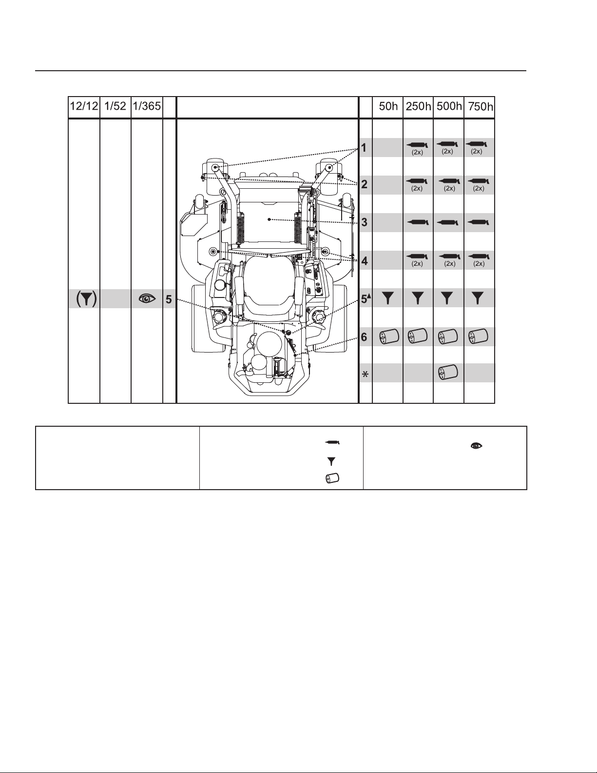
Lubrication Schedule
LUBRICATION
12/12 Every year
1/52 Every Week
1/365 Every day
Change hydraulic drive filters.
*
p Change engine oil every 50 hours.
General
Remove the ignition key to prevent unintentional
movements during lubrication.
When lubricating with an oil can, it must be filled with
engine oil.
When lubricating with grease, unless otherwise stated,
use high grade molybdenum disulphide grease.
For daily use, the machine should be lubricated twice
weekly.
Lubricate with grease gun
Oil change
Filter change
8065-031
Level check
Wipe away excess grease after lubrication.
It is important to avoid getting lubricant on the belts
or the drive surfaces on the belt pulleys. Should this
happen, attempt to clean them with spirits. If the belt
continues to slip after cleaning, it must be replaced.
Gasoline or other petroleum products must not be
used to clean belts.
50
50
Page 51
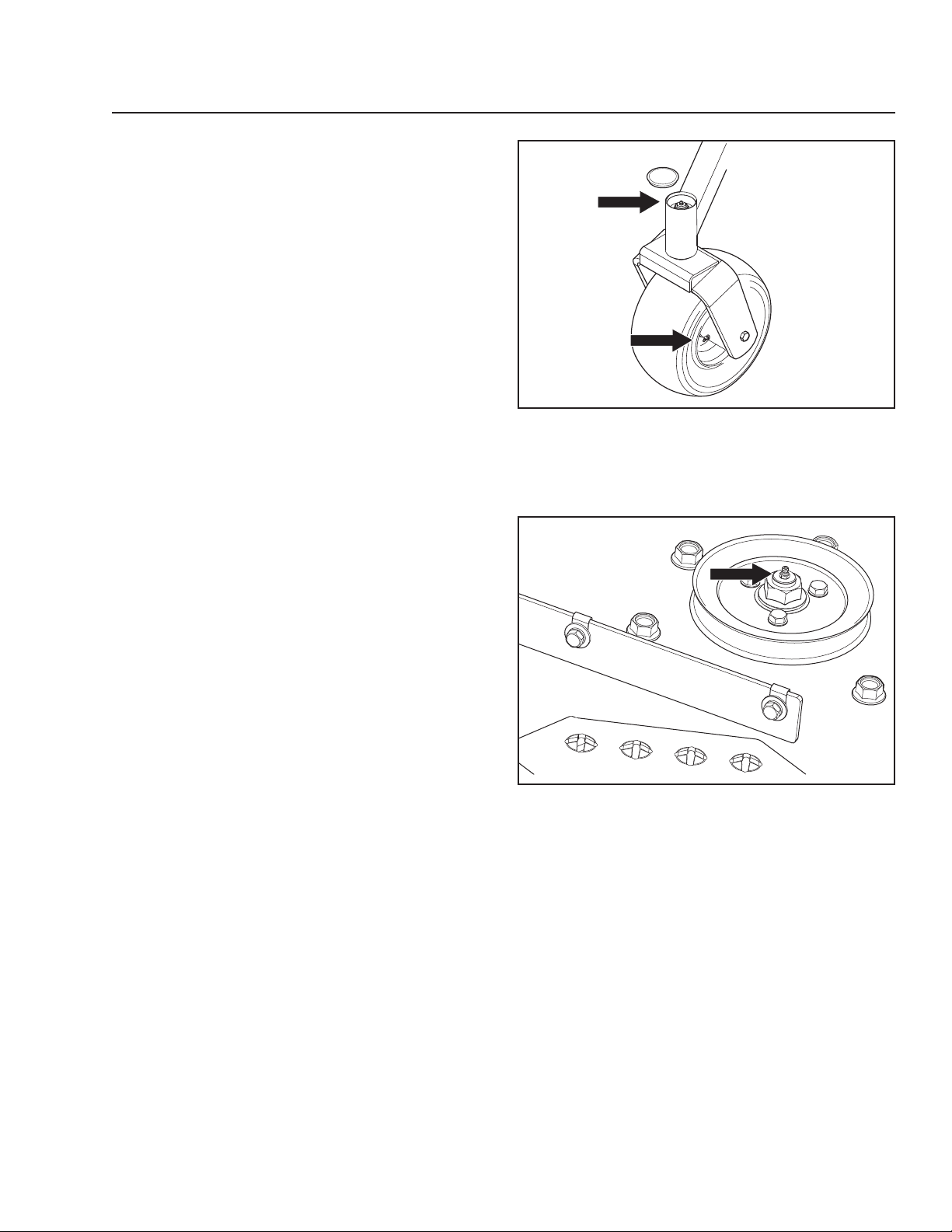
LUBRICATION
Wheel and Deck Zerks
Use only good quality bearing grease.
Grease from well-known brand names (petrochemical
companies, etc.) usually maintains a good quality.
Front Wheel Mount
Remove dust cap to expose zerk. Lubricate with a
grease gun until the grease is forced out around the
top washer.
Front Wheel Bearings
Lubricate 3-4 strokes with a grease gun on each set of
wheel bearings.
Deck Spindle
Lower the cutting deck completely.
If a grease gun without rubber hose is used, the foot
plate must be removed.
Lubricate with a grease gun, 2-3 strokes per spindle.
8065-032
Lubricating front wheels
Cables
If possible, grease both ends of the cables and move
the controls to end stop positions when lubricating.
Refit the rubber covers on the cables after lubrication.
Cables with sheaths will bind if they are not lubricated
regularly. If a cable binds, it can disrupt operation.
If a cable binds, remove the cable and hang it
vertically. Lubricate it with light engine oil until the oil
begins to escape from the bottom.
Deck spindle
8065-033
51
51
Page 52
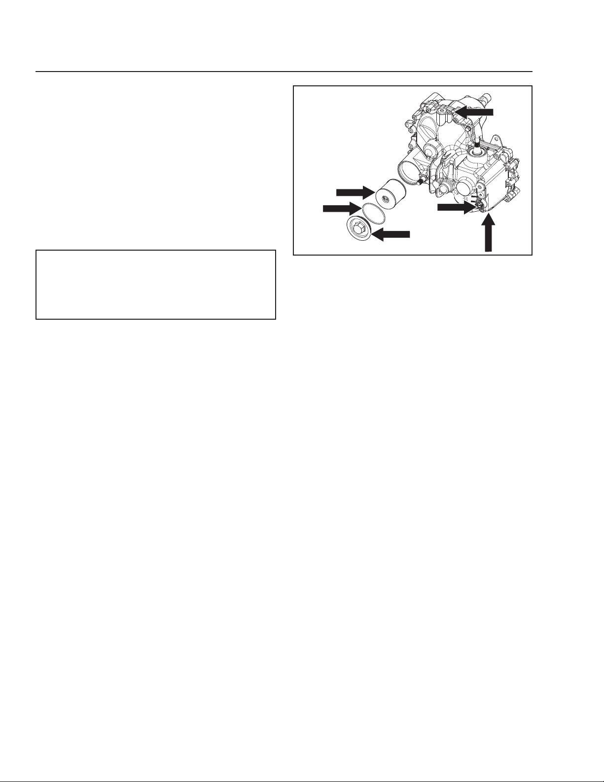
Hydraulic Drive - ZT5400
LUBRICATION
Fluid and Filter Change
This transaxle is designed with a servicable
filter. To ensure constant fluid quality levels and
longer life, an initial oil and filter change at 100
hours is recommended. Subsequent changes are
recommended at 400 hour intervals minimum, or
yearly, whichever comes first.
The following procedure can be performed with the
transaxle installed in the vehicle, and the vehicle on
level ground. Apply the bypass valve and lock the
vehicle parking brake.
Drain old oil filters of all free-flowing oil prior
to disposal. Place used oil in appropriate
containers and dispose of it in accordance
with laws in your area.
1. Place an oil drain pan (12" or more in diameter
and 8 qt. capacity is optimal) beneath the
oil filter. Remove the oil filter cover from the
transaxle to drain the oil. Remove the o-ring
from the cover and discard.
2. Remove the bottom oil fill vent port plug to drain
any residual oil.
3. After the oil has drained from the transaxle,
remove the oil filter from the transaxle housing.
4. Install the bottom oil fill vent port plug (torque
to 32 - 42 in-lbs [48.39-56.94 Nm]) and a new
filter. Install a new o-ring onto the filter cover
and install the filter cover (torque to 40-45 in-lbs
[54.23 - 61.01 Nm])
5. Remove the top oil fill vent port plug and fill the
transaxle with new 15W50 synthetic oil through
the expansion tank port/fill port until the oil
reaches the oil fill vent port.
6. Install the top oil fill vent port plug and continue
filling the system with oil until the fill line is
reached in the expansion tank. (Approximately
1½ gallons total per side)
7. Drain old oil filter of all free flowing oil prior
to disposal. Place used oil in appropriate
containers and deliver to an approved recycling
collection facility.
8. Proceed to the purge procedure.
1
2
3
1. Pump filter
2. O-ring
3. Filter cover
4. Bottom oil fill vent port
5. Top oil fill vent port
6. Bypass valve
ZT-5400 filter change
5
6
4
8065-036
52
52
Page 53

LUBRICATION
Transmission Purging Procedures
Due to the effects air has on efficiency in hydrostatic
drive applications, it is critical to purge the system.
These purge procedures should be implemented
any time a hydrostatic system has been opened to
facilitate maintenance or any additional oil has been
added to the system.
Resulting symptoms in hydrostatic systems may be:
• Noisy operation.
• Lack of power or drive after short term operation.
• High operation temperature and excessive
expansion of oil.
Before starting, make sure the oil tank is at the proper
oil level. If not, fill to the specifications outlined in this
section.
The following procedures are best performed with the
vehicle drive wheels off the ground, then repeated
under normal operating conditions.
1. Disengage the brake if activated.
2. With the bypass valve open and the engine
running at fast idle, slowly move the directional
control in both forward and reverse directions (5
or 6 times). As air is purged from the unit, the oil
level will drop.
3. With the bypass valve closed and the engine
running, slowly move the directional control in
both forward and reverse directions (5 to 6 times).
Check the oil level and add oil as required after
stopping the engine.
4. It may be necessary to repeat Steps 2 and 3 until
all the air is completely purged from the system.
When the hydraulic drive operates at normal noise
levels and moves smoothly forward and reverse at
normal speeds, the hydraulic drive is considered
purged.
5. After the vehicle has been used two times, the oil
level should be checked while the oil is cold and
adjusted accordingly.
53
53
Page 54

TROUBLESHOOTING
Problem Cause
Engine will not start • Blade switch is engaged.
• Steering controls are not locked in the neutral position
• Parking brake is not activated
• Battery is dead
• Contamination in the carburetor or fuel line.
• Fuel supply is closed or the shutoff valve for the fuel tank is in
the wrong position
• Clogged fuel filter or fuel line
• Ignition system faulty
Starter does not turn the engine over • Battery is dead
• Poor contact of the battery terminal cable connections
• Blown fuse
• Fault in the starter safety circuit. See Safety System in the
Maintenance Section
Engine runs rough • Faulty carburetor
• Choke control is pulled out with a warm engine
• Clogged fuel filter or jet
• Clogged ventilation valve on the fuel cap
• Fuel tank nearly empty
• Fouled spark plugs
• Rich fuel mixture or fuel-air mixture.
• Wrong fuel type
• Water in fuel
• Clogged air filter
Engine seems weak • Clogged air filter
• Fouled spark plugs
• Carburetor incorrectly adjusted
• Air trapped in hydraulic system
Machine vibrates • Blades are loose
• Blades are incorrectly balanced
• Engine is loose
54
Page 55

TROUBLESHOOTING
Problem Cause
Engine overheats • Clogged air intake or cooling fins
• Engine overloaded
• Poor ventilation around engine
• Defective engine speed regulator
• Too little or no oil in the engine
• Contamination in the carburetor or fuel line.
• Fouled spark plugs
Battery not charging • Poor contact of the battery terminal cable connections
• Charging lead is disconnected
The machine moves slowly, unevenly, or not at all • Parking brake on
• Bypass valve on pump open
• Drive belt for the transmission slack or has come off
• Air trapped in hydraulic system
Mower deck not engaging • Drive belt for the mower deck has come loose
• Contact for the electromagnetic coupling has loosened
• Blade switch is faulty or has come loose from cable
contact
• Blown fuse
Transaxle leaks oil • Damaged seals, housing, or gaskets
• Air trapped in hydraulic system
Uneven mowing results • Different air pressure in tires on the left and right sides.
• Bent blades
• Suspending for the mower deck is uneven
• Blades are dull
• Driving speed too high
• Grass is too long
• Grass collected under the mower deck
55
Page 56

STORAGE
Winter Storage
The machine should be readied for storage at the
end of the mowing season or if it will not be in use for
longer than 30 days.
Fuel allowed to stand for long periods of time (30 days
or more) can leave sticky residues that can plug the
carburetor and disrupt engine function.
Fuel stabilizers are an acceptable option as regards to
the sticky residues that can occur during storage.
Add stabilizer to the fuel in the tank or in the storage
container. Always use the mixing ratios specified by
the manufacturer of the stabilizer. Run the engine for
at least 10 minutes after adding the stabilizer so that
it reaches the carburetor. Do not empty the fuel tank
and the carburetor if a stabilizer has been added.
WARNING!
Never store an engine with fuel in the
tank indoors or in poorly ventilated
spaces where fuel vapor can come in
contact with open flames, sparks, or a
pilot light such as in a boiler, hot water
tank, clothes drier, etc. Handle the
fuel with care. It is very flammable and
can cause serious personal injury and
property damage. Drain the fuel into
an approved container outdoors and
far away from open flame. Never use
gasoline for cleaning. Use a degreaser
and warm water.
To ready the machine for storage, follow these steps:
1. Thoroughly clean the machine, especially under
the mower deck. Touch up damage to the paint
and spray a thin layer of oil on the underside of
the mower deck to avoid corrosion.
2. Inspect the machine for worn or damaged parts
and tighten any nuts or screws that may have
become loose.
3. Change the engine oil; dispose of properly.
4. Empty the fuel tanks or add a fuel stabilizer. Start
the engine and allow it to run until the carburetor
is drained of fuel or the stabilizer has reached the
carburetor.
5. Remove the spark plug and pour about a
tablespoon of engine oil into the cylinder. Turn
over the engine so that the oil is evenly distributed
and then refit the spark plug.
6. Lubricate all grease zerks, joints, and axles.
7. Remove the battery. Clean, charge, and store the
battery in a cool place, but protect it from direct
cold.
8. Store the machine in a clean, dry place and cover
it for extra protection.
Service
When ordering spare parts, please specify the
purchase year, model, type, and serial number.
Always use genuine Husqvarna spare parts.
An annual check-up at an authorized service
workshop is a good way to ensure that the machine
performs its best the following season.
56
Page 57
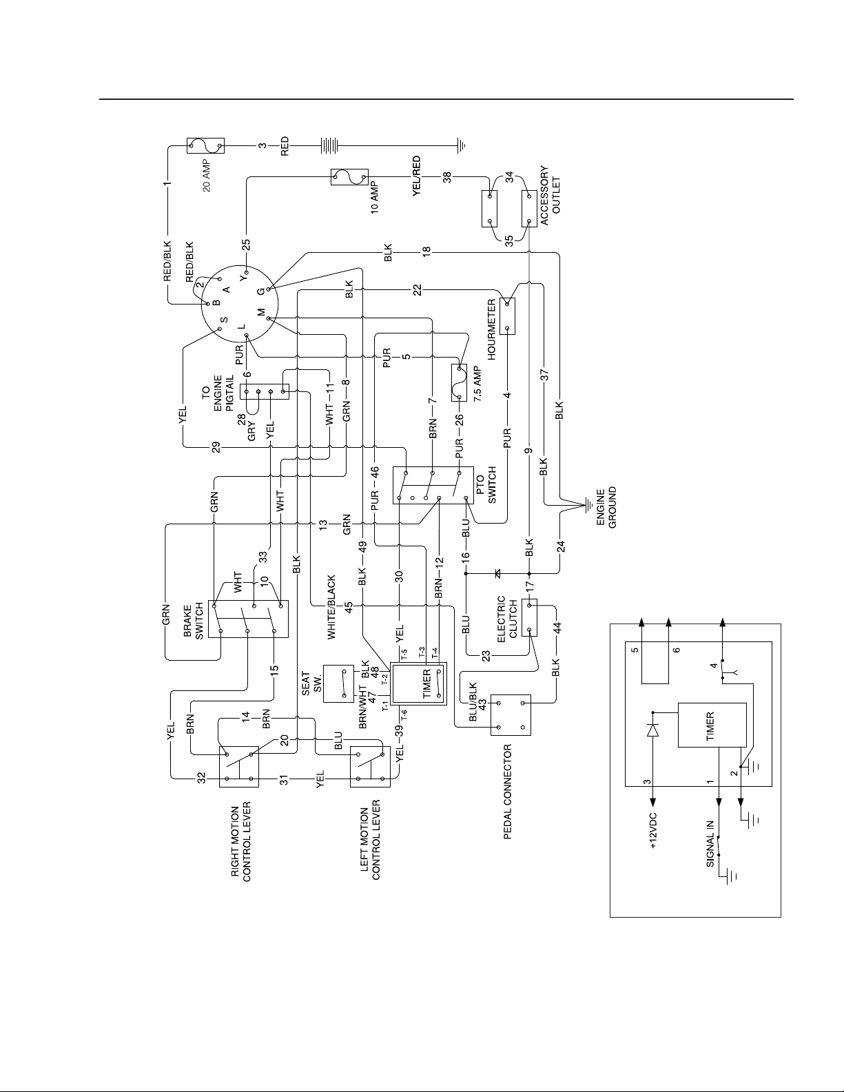
WIRING DIAGRAM
TIMER SCHEMATIC
57
Page 58

TECHNICAL DATA
PZ6034FX ZT
Engine
Manufacturer Kawasaki
Type FX921V
Power 31 HP* (23.1 Kw) @ 3600 rpm
Lubrication Pressure w/ Oil Filter
Fuel Min 87 octane unleaded (Max
ethyl alcohol 10%, Max MTBE 15%)
Fuel tanks capacity 11 gallons / 41.6 liters
Cooling Air cooled
Air filter Heavy duty canister
Alternator 12v 15 amp @ 3600 rpm
Starter Electric
Transmission
Transmission ZT5400
Speed and direction controls Dual levers, foam gripped
Speed forward 0-18 mph - 0-29 Km/h
(Transport speed)
Speed reverse 0-6 mph - 0-9.7 Km/h
Brakes Internal Wet Disc
Front caster tires, smooth tread 13 x 6.5 Flat Free
Rear tires, turf pneumatic 24 x 12-12 4 ply
Tire pressures 15 PSI / 103 kPa / 1 bar
1)
See the Engine Manufacturer's manual for engine
specifications.
2)
The power rating of the engines indicated is the average
net power output (at specified rpm) of a typical production
engine for the engine model measured to SAE standard
J1349/ISO1585. Mass production engines may differ from
this value. Actual power output for the engine installed
in the final machine will depend on the operating speed,
environmental conditions and other variables.
58
Page 59

TECHNICAL DATA
PZ6034FX ZT
Frame
Cutting Width 60" (152.4 cm)
Cutting Height 1"-5" (2.5-12.7 cm)
Uncut Circle 0
Number of Blades 3
Blade Length 21" / 53.3 cm
Antii-scalp Rollers 5 adjustable
Sprung Seat Suspension
Hinged Arm Rests Yes
Hour Meter Ye s
Blade Engagement 250 ft-lb Ogura
Deck Construction 7 gauge
Productivity 5.8 acres/h / 23,280 m
Dimension
Weight 1320 lbs / 599 kg
Base Machine Length 82½" / 210 cm
Base Machine Height 47½" / 121 cm
Base Machine Width 55" / 140 cm
Overall Width, Chute Up 61½" / 156 cm
Overall Width, Chute Down 73" / 185 cm
Overall Height, ROPS Up 72" / 183 cm
2
/h
59
Page 60
TECHNICAL DATA
Torque Specifications
Engine crankshaft bolt 50 ft/lb (67 Nm)
Deck pulley bolts 150 ft/lb (203 Nm)
Lug nuts 75 ft/lb (100 Nm)
Blade bolt 90 ft/lb (122 Nm)
HEX HEAD CAP SCREWS
The torque values shown should be used as a general guideline when specific torque values are not given.
U.S. Standard Hardware
Grade
Size ft./lbs Nm ft./lbs Nm ft./lbs Nm
¼ 9 12 13 18
5
/16 18 24 28 38 24 33
3
/8 31 42 46 62 40 54
7
/16 50 68 75 108
½ 75 102 115 156
9
/16 11 0 150 165 224
5
/8 150 203 225 305
¾ 250 339 370 502
7
/8 378 513 591 801
Shank Size (Diameter in inches, ne or
coarse thread)
11/8 782 1060 1410 1912
SAE Grade 5 SAE Grade 8 Flangelock Screw
** Grade 5 - Minimum commercial quality (lower quality not recommended)
Standard ¼" fasteners 9 ft/lb (12 Nm)
Standard 5/16" fasteners 18 ft/lb (25 Nm)
Standard 3/8" fasteners 33 ft/lb (44 Nm)
Standard 7/16" fasteners 52 ft/lb (70 Nm)
Standard ½" fasteners 80 ft/lb (110 Nm)
w/Flangelock Nut
Grade
Size ft./lbs Nm ft./lbs Nm ft./lbs Nm
M4 1.5 2 2.2 3 2.7 3.6
M5 3 4 4.5 6 5.2 7
M6 5.2 7 7.5 10 8.2 11
M7 8.2 11 12 16 15 20
M8 13.5 18 18.8 25 21.8 29
M10 24 32 35.2 47 43.5 58
M12 43.5 58 62.2 83 75 100
M14 70.5 94 100 133 11 9 159
M16 108 144 147 196 176 235
M18 142 190 202 269 242 323
M20 195 260 275 366 330 440
M22 276 368 390 520 471 628
M24 353 470 498 664 596 794
Shank Size (Diameter in inches, ne or coarse thread)
M27 530 707 474 996 904 1205
Grade 8.8
Metric Standard Hardware
Grade 10.9 Grade 12.9
60
Page 61

CONFORMITY CERTIFICATES
USA requirements
Labels are placed on the engine and/or in the engine
compartment stating that the machine will fulfill the
requirements. This is also applicable to special
requirements for any of the states, (California emission
rules etc.). Do not remove any of these labels.
Certificates can also be supplied with the machine at
delivery or written in the Engine manual. Take care of
them as they are valuable documents.
61
Page 62

SERVICE JOURNAL
Action
Delivery Service
Charge and connect the battery.
Adjust the tire pressure of all wheels to 15 PSI (1 bar).
Connect the contact box to the cable for the seat’s safety switch.
Check hydraulic oil level.
Check hydraulic hoses for kinking or leaks.
Check neutral position.
Fill with fuel and open the fuel shut off valve.
Start the engine.
Check that there is drive to both wheels.
Check the mower deck pitch and adjustment.
Check:
Safety switch for the parking brake.
Safety switch for the mower deck.
Safety switch in the seat.
Safety switch in the steering controls.
Parking brake functionality and adjustment.
Driving forward.
Driving backward.
Engaging the blades.
Check the idle speed
Check the engine high idle speed
Inform the customer about:
Date, mtr reading, stamp, sign
¨
¨
¨
¨
¨
¨
¨
¨
¨
¨
¨
¨
¨
¨
¨
¨
¨
¨
¨
¨
The need and advantages of following the service schedule.
The need and advantages of leaving the machine for service.
The effects of service and maintaining a service journal on the
machine’s resale value.
Application areas for mulching.
Fill in the sales papers, etc. Delivery service has
been carried out.
No remaining notes.
Certified:
62
¨
¨
¨
¨
Page 63

SERVICE JOURNAL
Action
After 10 hours
Change the engine oil.
Change the oil filter.
Check hydraulic oil level.
Inspect hydraulic hoses.
Inspect hydraulic belt
Inspect hydraulic filter.
Check neutral position.
Check safety system.
Check seat belt.
Check ROPS.
Check fuel system for leaks.
Date, mtr reading, stamp, sign
¨
¨
¨
¨
¨
¨
¨
¨
¨
¨
¨
Inspect safety guards and shields.
Check brake adjustment.
¨
¨
63
Page 64

SERVICE JOURNAL
Action
Daily Service
Clean debris from mower.
Check engine oil level.
Check the tire pressures.
Check underside of deck.
Inspect deck pulleys.
Check/clean the engine’s cooling air intake.
Check safety system.
Check seat belt.
Check ROPS.
Check fuel system for leaks.
Inspect safety guards and shields.
Date, mtr reading, stamp, sign
¨
¨
¨
¨
¨
¨
¨
¨
¨
¨
¨
Check brake adjustment.
¨
64
Page 65

SERVICE JOURNAL
Action
50-Hour Service
Clean debris from mower.
Check engine oil level.
Check the tire pressures.
Check underside of deck.
Inspect deck pulleys.
Check/clean the engine’s cooling air intake.
Check safety system.
Check seat belt.
Check ROPS.
Check fuel system for leaks.
Inspect safety guards and shields.
Date, mtr reading, stamp, sign
¨
¨
¨
¨
¨
¨
¨
¨
¨
¨
¨
Check brake adjustment.
¨
65
Page 66

SERVICE JOURNAL
Action
250-Hour Service
Grease fittings (caster pivots and caster wheels)
Inspect dampers
Inspect frame
Inspect throttle and choke cables
Inspect hardware
Check the tire pressures
Change the engine oil and filter
Change air filter
Inspect spark plug
Inspect fuel filter
Check engine RPM
Clean underside of deck
Check blade pitch
Grease blade spindles
Inspect spindle bearings
Inspect deck belt and blades
Inspect idler arm bearings
Inspect deck idler pulleys
Check hydraulic oil level
Inspect hydraulic filter
Inspect hydraulic drive belt
Inspect hydraulic hoses
Check neutral position
Inspect battery connections
Check safety system
Check seat belt
Check ROPS
Check fuel system for leaks
Inspect safety guards and shields
Check brake adjustment
Date, mtr reading, stamp, sign
¨
¨
¨
¨
¨
¨
¨
¨
¨
¨
¨
¨
¨
¨
¨
¨
¨
¨
¨
¨
¨
¨
¨
¨
¨
¨
¨
¨
¨
¨
66
Page 67

SERVICE JOURNAL
Action
500-Hour Service
Grease fittings (caster pivots and caster wheels)
Inspect dampers
Inspect frame
Inspect throttle and choke cables
Inspect hardware
Check the tire pressures
Change the engine oil and filter
Change air filter
Inspect spark plug
Inspect fuel filter
Check engine RPM
Clean underside of deck
Check blade pitch
Grease blade spindles
Inspect spindle bearings
Inspect deck belt and blades
Inspect idler arm bearings
Inspect deck idler pulleys
Change hydraulic oil level
Change hydraulic filter
Replace hydraulic drive belt
Inspect hydraulic hoses
Check neutral position
Inspect battery connections
Load test battery
Clean electrical connections
Inspect the clutch
Check safety system
Check seat belt
Check ROPS
Check fuel system for leaks
Inspect safety guards and shields
Check brake adjustment
Date, mtr reading, stamp, sign
¨
¨
¨
¨
¨
¨
¨
¨
¨
¨
¨
¨
¨
¨
¨
¨
¨
¨
¨
¨
¨
¨
¨
¨
¨
¨
¨
¨
¨
¨
¨
¨
¨
67
Page 68

SERVICE JOURNAL
Action
At Least Once Each Year
Clean the engine’s cooling air intake.
Replace the air cleaner’s pre-filter (foam).
Replace the air filter’s paper cartridge.
Change the engine oil.
Replace the engine oil filter
Check/adjust the cutting height
Check/adjust the parking brake
Clean/Change the spark plugs
Inspect spark plug
Check the engine valve clearance
Check the engine valve clearance
Date, mtr reading, stamp, sign
¨
¨
¨
¨
¨
¨
¨
¨
¨
¨
¨
68
Page 69

SERVICE JOURNAL
Action
Date, mtr reading, stamp, sign
69
Page 70

SERVICE JOURNAL
Action
Date, mtr reading, stamp, sign
70
Page 71

Page 72

www.husqvarna.com
115 462327 Rev A 2011-11-10
 Loading...