


Manual de Instrucciones |
HDS650 |
|
|
Pistola de Pulverización con
Alimentación por Sifón
Garantía Limitada - Pistolas Pulverizadoras Husky de Campbell Hausfeld
1DURACION: A partir de la fecha de compra por el comprador original tal como se especifica a continuación: Productos Estándard (Standard Duty) - Un año, Productos Resistentes (Serious Duty) -Dos años, Productos Robustos (Extreme Duty) - Tres años.
2.QUIEN OTORGA ESTA GARANTIA (EL GARANTE: Campbell Hausfeld / The Scott Fetzer Company 100 Production Drive, Harrison, Ohio 45030 Teléfono: (800) 543-6400
3.QUIEN RECIBE ESTA GARANTIA (EL COMPRADOR): El comprador original (que no sea un revendedor) del producto Campbell Hausfeld.
4.PRODUCTOS CUBIERTOS POR ESTA GARANTIA: Cualquier clavadora, grapadora, herramienta neumática, pistola pulverizadora, inflador o accesorio neumático suministrado o fabricado por el Garante.
5.COBERTURA DE LA GARANTIA: Los defectos substanciales de material y fabricación que ocurran dentro del período de validez de la garantía.
6.LO QUE NO ESTA CUBIERTO POR ESTA GARANTIA:
A.Las garantías implícitas, incluyendo aquellas de comercialidad E IDONEIDAD PARA FINES PARTICULARES, ESTAN LIMITADOS A LO ESPECIFICADO EN EL PARRAFO DE DURACION. Si este producto es empleado para uso comercial, industrial o para renta, la garantía será aplicable por noventa (90) días a partir de la fecha de compra. En algunos estados no se permiten limitaciones a la duración de las garantías implícitas, por lo tanto, en tales casos esta limitación no es aplicable.
B.CUALQUIER PERDIDA DAÑO INCIDENTAL, INDIRECTO O CONSECUENTE QUE PUEDA RESULTAR DE UN DEFECTO, FALLA O MALFUNCIONAMIENTO DEL PRODUCTO CAMPBELL HAUSFELD. En algunos estados no se permite la exclusión o limitación de daños incidentales o consecuentes, por lo tanto, en tales casos esta limitación o exclusión no es aplicable
C.Cualquier falla que resulte de un accidente, abuso, negligencia o incumplimiento de las instrucciones de funcionamiento y uso indicadas en el (los) manual(es) que se adjunta(n) al producto. Dichos accidentes, abusos por parte del comprador, o falta de operar el producto siguiendo las instrucciones del manual de instrucciones suministrado también debe incluir la desconexión o modificación de los instrumentos de seguridad. Si dichos instrumentos de seguridad son desconectados, la garantía quedaría cancelada.
D.Los ajustes normales explicados en el(los) manual(es) suministrado(s) con el producto.
E.Artículos o servicios normalmente requeridos para el mantenimiento del producto, tales como: anillos en O, resortes, amortiguadores, defensas, hojas de impulsor, fusibles, baterías, empaques, almohadillas o sellos, boquillas de fluído, agujas, boquillas para rociar arena, lubricantes, mangueras de material, elementos filtrantes, álabes de motores, abrasivos, hojillas, discos para cortar, cinceles, retenes para cinceles, cortadores, collarines, mandriles, mordazas para remachadoras, brocas para desarmadores, almohadillas para lijar, soportes de almohadillas, mecanismo de impacto o cualquier otro artículo desgastable que no se haya enumerado específicamente . Estos artículos sólo estarán cubiertos bajo esta garantía por noventa (90) días a partir de la fecha de compra original. Los artículos subrayados sólo están garantizados por defectos de material o fabricación.
7.RESPONSABILIDADES DEL GARANTE BAJO ESTA GARANTIA: Reparar o reemplazar, como lo decida el Garante, los productos o componentes que estén defectuosos, se hayan dañado o hayan dejado de funcionar adecuadamente, durante el período de validez de la garantía
8.RESPONSABILIDADES DEL COMPRADOR BAJO ESTA GARANTIA:
A.Suministrar prueba fechada de compra y la historia de mantenimiento del producto.
B.Entregar o enviar el producto o componente Campbell Hausfeld al Centro de Servicio autorizado Campbell Hausfeld más cercano. Los gastos de flete, de haberlos, deben ser pagados por el comprador.
C.Seguir las instrucciones sobre operación y mantenimiento del producto, tal como se indica(n) en el (los) manual(es) del propietario
9.CUANDO EFECTUARA EL GARANTE LA REPARACION O REEMPLAZO CUBIERTO BAJO ESTA GARANTIA: La reparación o reemplazo dependerá del flujo normal de trabajo del centro de servicio y de la disponibilidad de repuestos.
Esta garantía limitada es válida sólo en los EE.UU., Canadá y México y otorga derechos legales específicos. Usted también puede tener otros derechos que varían de un Estado a otro. o de un país a otro.
See Warranty on page 10 for important information about commercial use of this product.
Operating Instructions and Parts Manual |
HDS650 |
|
|
Please read and save these instructions. Read carefully before attempting to assemble, install, operate or maintain the product described. Protect yourself and others by observing all safety information. Failure to comply with instructions could result in personal injury and/or property damage! Retain instructions for future reference.
Siphon-Feed
Spray Gun
Description
A conventional siphon feed spray gun designed to spray all light to medium viscosity materials. Enamels, lacquers, polyurethane, urethane and all primers can be sprayed. Spray gun has fluid and pattern controls and is supplied with a 1 quart anti-drip siphon cup.
Specifications
Feed Type |
Siphon |
Mix Type |
External |
Bleed Type |
Non-bleeder |
Fluid Nozzle I.D. |
.071” (1.8 mm) |
Max. Inlet |
|
Air Pressure |
70 PSIG |
Air Req’d. |
7.0 average |
(SCFM @ 40 PSI) |
10.4 continuous |
Pattern Size |
9.5” @ 40 PSI |
|
8” Distance |
|
from workpiece |
Air Inlet |
1/4 NPS (M) |
Fluid Inlet |
3/8 NPS (M) |
Fluid Nozzle |
Heat-treated |
Material |
alloy steel |
Fluid Needle |
|
Material |
Stainless Steel |
Safety Guidelines
This manual contains information that is very important to know and understand. This information is provided for SAFETY and to PREVENT EQUIPMENT PROBLEMS. To help recognize this information, observe the following symbols.
Danger indicates
! DANGER an imminently hazardous situation which, if not avoided, WILL result in death or serious injury.
Warning indicates ! WARNING a potentially haz-
ardous situation which, if not avoided, COULD result in death or serious injury.
Caution indicates a ! CAUTION potentially haz-
ardous situation which, if not avoided, MAY result in minor or moderate injury.
NOTICE |
Notice indicates |
|
important infor- |
||
|
mation, that if not followed, may cause damage to equipment.
Unpacking
After unpacking the product, inspect carefully for any damage that may have occurred during transit. Make sure to tighten fittings, bolts, etc., before putting unit into service.
Do not operate ! WARNING tool if damaged
during shipping, handling or use. Damage could result in bursting and cause injury or property damage.
Spray Gun Terms
FEED – Method used to bring paint into the gun for spraying.
PRESSURE FEED – Method of paint feed where a canister or paint tank is pressurized to force paint to the gun. Either internal or external mix air caps are used with this method. Pressure feed is generally used for spraying heavy bodied paints or for large size projects.
SIPHON FEED – Method of paint feed where atmospheric pressure creates a partial vacuum to siphon paint to the gun. Only external mix air caps are used with this method. Siphon feed is
used with light bodied paints.
GRAVITY FEED – Method of paint feed similar to the siphon feed method. However, the cup is inverted to create a positive fluid pressure at the nozzle.
MIX – The mixing of paint and air when spraying.
INTERNAL MIX – Process where the air and paint are mixed inside the air cap just before being sprayed. This method is best for heavy bodied, slow drying paints and can only be used with the pressure feed method. Do not use fast drying paints with internal mix. The paint will dry inside and quickly clog the air cap.
EXTERNAL MIX – Process where the air and paint are mixed just after leaving the nozzle. This type of mix should be used for fast drying paints and when a high quality finish is needed.
BLEEDER/NON-BLEEDER – Indicates whether air flows through the gun continuously or as the trigger is pulled.
BLEEDER – In this mode, air passes continuously through the gun whether spraying or not. This mode is generally used when the air is supplied by a continuously running compressor that does not have a tank.
NON-BLEEDER – In this mode, air flows only when the trigger is pulled. This type of operation is used with a compressor equipped with a tank or with a large factory air system.
VISCOSITY – A measurement of the resistance of the flow of a liquid.
ATOMIZATION - Conversion of liquid to spray droplets (mist).
PATTERN CONTROL KNOB – Used to form the proper pattern (size and
REMINDER: Keep your dated proof of purchase for warranty purposes! Attach it to this manual or file it for safekeeping.
© 2002 |
IN285500AV 12/02 |

Operating Instructions and Parts Manual |
HDS650 |
Siphon-Feed Spray Gun
Spray Gun Terms (Cont.)
shape) of paint as it is sprayed from the gun to the work piece.
FLUID CONTROL KNOB – Used to control the amount of paint being mixed with air.
PAINT TANK – An auxiliary pressurized paint reservoir that allows continuous spraying of large amounts of paint without stopping for refills as with a canister. It also allows using the spray gun at any angle or orientation.
General Safety
Information
1.Read all manuals included with this product carefully. Be thoroughly familiar
MANUAL
with the controls and the proper use of the equipment.
2.Follow all local electrical and safety codes as well as in the United States, the National Electrical Codes (NEC) and Occupational Safety and Health Act (OSHA).
! WARNING
Use a face mask/respirator and protective cloth-
ing when spraying. Always spray in a well ventilated area to pre-
vent health and fire hazards. Refer to Material Safety Data Sheets (MSDS) of spray material for details.
! DANGER
Never spray closer than 25 feet to the compressor! If possible, locate compressor in separate
room. Never spray into the compressor, compressor controls or the motor.
3.Do not smoke or eat when spraying paint, insecticides, or other flammable substances.
! WARNING
Do not spray flammable materials in vicinity of open flame or near igni-
tion sources. Motors, electrical equipment and controls can cause electrical arcs that will ignite a flammable gas or vapor. Never store flammable liquids or gases in the vicinity of the compressor.
4.When spraying and cleaning, always follow the instructions and safety precautions provided by the material manufacturer (Refer to MSDS).
Do not spray acids, ! WARNING corrosive materials, toxic chemicals, fertilizers or pesticides.
Using these materials could result in death or serious injury.
5.Keep visitors away and NEVER allow children or pets in the work area.
! WARNING |
Never aim or |
|
spray at yourself or |
||
|
anyone else or serious injury could occur.
6.Always work in a clean environment. To avoid injury and damage to the workpiece, do not aim the spray gun at any dust or debris.
! WARNING
Do not use pressure that exceeds the operating pressure of any of the
parts (hoses, fittings,
etc.) in the painting system.
Keep hose away
! CAUTION from sharp objects. Bursting air hoses may cause injury. Examine air hoses regularly and replace if damaged.
7.Always use a pressure regulator on the air supply to the spray gun.
NOTICE |
Failure to install |
|
appropriate |
||
|
water/oil removal equipment may result in damage to machinery or workpiece.
Types of Spray Gun
Set-Ups
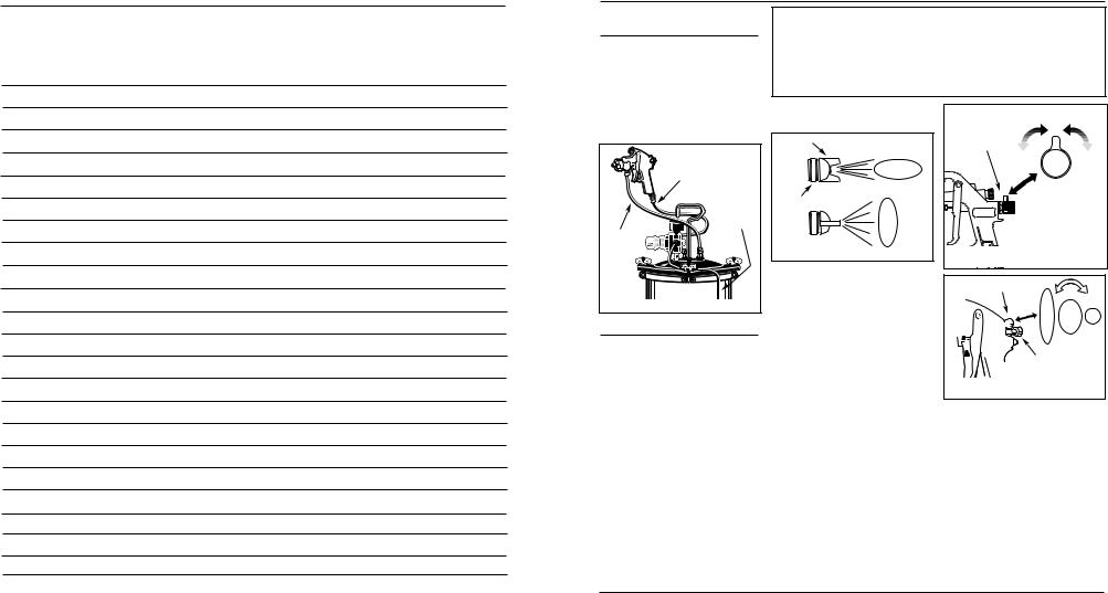
SIPHON FEED CUP SET-UP
The air pressure for atomization is controlled by the regulator on the air source. The amount of fluid is adjusted by the fluid control knob, the paint viscosity, and the air pressure (See Figure 1). The siphon cup must be vented to the atmosphere.
Fluid Control
Knob
Filtered,
Regulated
Air Source
Figure 1 - Siphon Feed Cup Set-up
PRESSURE FEED CUP SET-UP
Air pressure for atomization is controlled by the regulator on the air source. The fluid pressure is set by adjusting the cup regulator. The amount of fluid is also adjusted by the fluid control knob (See Figure 2). This method is required for heavy fluids and when using internal mix nozzle spraying. This method generally requires a special fluid tip, needle and air cap set.
 Fluid Control
Knob
Fluid Pressure
Regulator
Filtered,
Regulated
Air Source
Cup Pressure Hose
Figure 2 - Pressure Feed Cup Set-up
Manuel de Instrucciones y Lista de Piezas |
HDS650 |
|
|
Notas
31 Sp
2
Manuel de Instrucciones y Lista de Piezas |
HDS650 |
|
Operating Instructions and Parts Manual |
HDS650 |
|
|
|
|
|
Pistola de Pulverización con
Alimentación por Sifón
Notas
Types of Spray Gun
Set-Ups
PRESSURE FEED TANK SET-UP
This method is the same as the pressure feed cup set-up except that the gun can be oriented in any position independent of the tank (See Figure 3). This method is useful for medium production or large scale spraying applications.
Air to Spray Gun
Filtered,
Regulated
Air Source
Fluid
Hose
Pressure Tank
Figure 3 - Pressure Feed Tank Set-up
Preparation
1.Thoroughly mix the paint in accordance with the manufacturer’s instructions, adding thinner where necessary. Most materials will spray readily if thinned properly. Strain material through cheese cloth or a paint strainer. Test the consistency of the material by making a few strokes on a cardboard target. If material still appears too thick, add a small amount of thinner. THIN WITH CARE!
2.Fill the canister about 3/4 full and start the air compressor.
3.Set up a piece of cardboard or other scrap material to use as a target and adjust for best spray pattern.
FAN DIRECTION
The direction of the fan (horizontal or vertical) can be changed by loosening the lock ring and turning the air cap 90
WATER/OIL IN COMPRESSED AIR
All compressor pumps discharge some condensed water, oil or contaminates with the compressed air.
IMPORTANT: This condensation will cause “fish eyes” to appear in the paint job. Install appropriate water/oil removal equipment and controls as necessary for the intended application.
NOTICE |
Failure to install appropriate water/oil removal equipment |
may result in damage to machinery or workpiece. |
|
|
|
degrees (See Figure 4). Hand tighten lock ring after adjustment.
Air Cap
Horizontal Fan
Vertical Fan
Lock Ring
Figure 4
PATTERN ADJUSTMENT
SIPHON FEED
1.Adjust air pressure to the spray gun according to the recommendations supplied with the spray material. This air pressure usually falls between 40 - 60 PSI. Adjust air pressure with the trigger pulled and air control knob (if applicable) fully open. If reduced air pressure is desired for some areas of the spray job, use air control knob to reduce pressure as necessary (See Figure 5).
2.Set pattern size to desired shape. For full pattern, open pattern control knob by turning counterclockwise. For a round pattern, turn pattern control knob clockwise (See Figure 6).
3.Turn fluid control knob fully clockwise until closed (See Figure 6).
4.Trigger a short burst while turning fluid control knob counterclockwise. Observe the spray pattern on the target and adjust the fluid control knob until the desired pattern (atomization) is obtained (See Figure 7).
|
Increase |
|
Air Flow |
Air Control |
|
Knob |
|
|
Decrease |
|
Air Flow |
Figure 5 - |
Air Adjustment on |
|
EEDAIRESpray Gun |
|
P |
Pattern control knob
Fluid control knob
Figure 6 - Pattern Size
If the spray is too fine (excessive overspray), caused by too much air for the amount of paint being sprayed, reduce the air pressure or open the fluid control to spray more material.
If the spray is too coarse (spitting globs), reduce the amount of material with the fluid control knob or thin the paint.
PRESSURE FEED SET-UP
1.Adjust air pressure to the spray gun according to the recommendations supplied with the spray material. This
30 Sp
3
Operating Instructions and Parts Manual |
HDS650 |
Siphon-Feed Spray Gun
Preparation (Cont.)
air pressure usually falls between 40 - 60 PSI. Adjust air pressure with the trigger pulled and air control knob (if applicable) fully open. If reduced air pressure is desired for some areas of the spray job, use air control knob to reduce pressure as necessary (See Figure 5).
2.Set pattern size to desired shape. For full pattern, open pattern control knob by turning counterclockwise. For a round pattern, turn pattern control knob clockwise (See Figure 6).
3.Open the fluid control knob by turning counterclockwise about three turns.
4.Start the tank pressure at 0 PSI and turn the tank regulator slowly to increase fluid delivery until the desired pattern consistency (atomization) is reached.
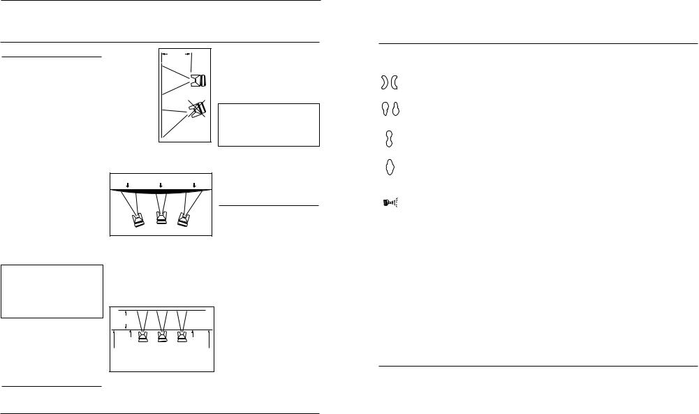
5.If the atomization is too coarse, reduce the tank pressure with the tank regulator. Trigger a short burst or open relief valve to relieve the pressure, then increase pressure slowly to obtain proper pattern consistency (See Figure 7).
Paint too |
Correct |
Paint too |
fine |
|
coarse |
Figure 7 - Pattern Consistency
(Atomization)
6.The fluid control knob can be used to finely adjust pattern consistency.
Before spraying the workpiece, practice a few minutes on a cardboard target to ensure the pattern size and consistency are set correctly.
Operation
1.Begin spraying. Always keep the gun at right angles to the work (See Figure 8).
Keep the nozzle about 6 to 9 inches from the work surface throughout the stroke and always keep the gun in motion while spraying. Stopping gun movement in midstroke will cause a build up of paint and result in “runs.” Do not “fan” the
gun from side to side while painting. This will cause a build-up of paint in the center of the stroke and an insufficient coating at each end (See Figure 9).
Thin coat Heavy coat Thin coat INCORRECT
Figure 9
2.“Trigger” the gun properly. Start the gun moving at the beginning of the stroke BEFORE SQUEEZING THE TRIGGER and release the trigger BEFORE STOPPING GUN MOVEMENT at the end of the stroke. This procedure will “feather” (blend) each stroke with the next without showing overlap or unevenness (See Figure 10).
6 - 9” |
|
Pull |
Release |
Trigger |
Trigger |
Start |
End |
Stroke |
Stroke |
Figure 10 |
|
3.The amount of paint being applied can be varied by the speed of the
stroke, distance from the surface and
adjustment of the fluid control knob.
4.Overlap strokes just enough to obtain an even coat (See Figure 11). NOTE: Two thin coats of paint will yield better results and have less chance of runs than one heavy layer.
Figure 11
5.Use a piece of cardboard as a shield to catch overspray at the edges of the work to protect other surfaces. Use masking tape to cover other areas if needed.
Maintenance
DAILY CLEAN-UP
Local codes may require specific cleaning methods and equipment. Follow local codes and manufacturer’s recommendations for the use and disposal of spray materials and solvent.
NOTICE |
Clean spray gun |
|
immediately after |
||
|
use. Paint and other material dry quickly in the small passages rendering gun useless due to the difficulty of removing hardened paint from the passages inside the gun.
NOTE: In the instructions below, the use of the word “solvent” refers to the specific solvent for the material used (eg: lacquer thinner for lacquer, etc ).
1.Spray guns with canister—Remove and empty the canister; then rinse with a solvent recommended for the paint or other material used.
2.Refill canister with clean solvent and attach to the gun. Spray solvent through the gun while shaking the gun vigorously. Wipe the gun exterior with a solvent soaked rag. Repeat until the gun is clean.
3.Remove the air cap and soak in sol
Manuel de Instrucciones y Lista de Piezas |
HDS650 |
|
|
Guía de Diagnóstico de Averías
|
|
Problema |
Posible(s) Causa(s) |
Acción a Tomar |
||||||||
|
|
|
Acumulación de |
1. |
Los orificios a los lados de la boquilla |
1. |
Límpielos. Use sólo pintura no metálica |
|||||
|
|
|
||||||||||
|
|
|
pintura a la |
|
de aire están tapados |
|
|
|
|
|||
|
|
|
derecha o izquier- |
2. |
Acumulación de impurezas a los lados |
2. |
Límpiela |
|||||
|
|
|
da |
|
de la boquilla |
|
|
|
|
|||
|
|
|
|
|
|
|
|
|
|
|
|
|
|
|
|
|
|
Acumu-lación de |
1. |
Acumulación de material reseco en la |
1. |
Límpiela |
|||
|
|
|
|
|||||||||
|
|
|
|
|
pintura en la parte |
|
parte superior o inferior de la boquilla |
|
|
|
|
|
|
|
|
|
|
superior o inferior |
2. |
La tapa de aire está floja o el asiento |
2. |
Límpiela y apriétela |
|||
|
|
|
|
|
|
|
|
está sucio |
3. |
Límpiela. Use sólo pintura no metálica |
||
|
|
|
|
|
|
|
3. |
La tapa de aire está obstruída |
||||
|
|
|
|
|
|
|
|
|
|
|
|
|
|
|
|
|
|
|
|
|
|
|
|
|
|
|
|
|
|
|
Acabado |
1. |
El control del patrón está muy abierto |
1. |
Cierre parcialmente el control de fluído |
|||
|
|
|
|
|
disparejo |
2. |
El control de fluído está muy bajo |
2. |
Aumente el nivel de fluído |
|||
|
|
|
|
|
3. |
Está atomizando demasiado aire |
3. |
Reduzca la presión de atomización |
||||
|
|
|
|
|
|
|
4. |
La presión es muy baja (sólo en los sis- |
4. |
Aumente la presión del fluído |
||
|
|
|
|
|
|
|
|
temas a presión) |
|
|
|
|
|
|
|
|
|
|
|
|
|
|
|
|
|
|
|
|
|
|
Acumu-lación de |
1. |
El control de rocío está cerrado parcial- |
1. |
Ábralo un poco |
|||
|
|
|
|
|
pintura en el cen- |
|
mente |
2. |
Diluya el material hasta alcanzar la viscosidad adecuada |
|||
|
|
|
|
|
tro |
2. |
El material está muy espeso |
|||||
|
|
|
|
|
|
|
3. |
La presión de atomización es muy baja |
3. |
Aumente la presión de atomización |
||
|
|
|
|
|
|
|
4. |
La presión del fluído es muy alta (en los |
4. |
Reduzca la presión del fluído o cierre un poco la perilla de |
||
|
|
|
|
|
|
|
|
control de fluído |
||||
|
|
|
|
|
|
|
|
sistemas a presión) |
|
|||
|
|
|
|
|
|
|
|
|
|
|
|
|
|
|
|
|
|
|
|
|
|
|
|
|
|
|
|
|
|
|
|
Rocío salpicado |
1. |
El nivel de material es muy bajo |
1. |
Añádale más material |
||
|
|
|
|
|
|
|||||||
|
|
|
|
|
|
|
2. |
El envase está muy inclinado |
2. |
Colóquelo más derecho |
||
|
|
|
|
|
|
|
3. |
Apriétela |
||||
|
|
|
|
|
|
|
3. |
La conexión del suministro de fluído |
||||
|
|
|
|
|
|
|
|
está floja |
4. |
Ajústela o reemplácela |
||
|
|
|
|
|
|
|
4. |
La boquilla o el asiento están flojos o |
||||
|
|
|
|
|
|
|
|
dañados |
5. |
Lubríquela o apriétela |
||
|
|
|
|
|
|
|
|
|||||
|
|
|
|
|
|
|
5. |
La tuerca que sostiene el empaque de |
||||
|
|
|
|
|
|
|
|
la aguja está floja o dañada |
6. |
Destápelo |
||
|
|
|
|
|
|
|
6. |
El orificio de ventilación está obstruído |
||||
|
|
|
|
|
|
|
|
(sólo en los sistemas de sifón) |
|
|
|
|
|
|
|
|
|
|
|
|
|
||||
|
|
Fuja de fluído a través de la |
1. |
La tuerca que sostiene el empaque está |
1. |
Apriétela, pero sin restringir la aguja |
||||||
|
|
tuerca de empaque de la |
|
floja |
2. |
Reemplácela o lubríquela (con aceite sin silicón) |
||||||
|
|
aguja |
2. |
El empaque está desgastado o seco |
||||||||
|
|
|
|
|
|
|
|
|
||||
|
|
El aire se fuga a través de la |
1. |
El vástago de la válvula se atasca |
1. |
Lubríquelo |
||||||
|
|
boquilla de aire aún sin |
2. |
La válvula de aire o el asiento están conta- |
2. |
Límpielos |
||||||
|
|
apretar el gatillo |
|
minados |
3. |
Reemplácela |
||||||
|
|
|
|
|
|
|
3. |
La válvula de aire o el asiento están des- |
||||
|
|
|
|
|
|
|
|
gastados o dañados |
4. |
Reemplácela |
||
|
|
|
|
|
|
|
4. |
El resorte de la válvula de aire está roto |
||||
|
|
|
|
|
|
|
5. |
Reemplácela |
||||
|
|
|
|
|
|
|
5. |
El vástago de la válvula está torcido |
||||
|
|
|
|
|
|
|
|
|
|
|
||
|
|
|
|
|
|
|
|
|||||
|
|
El fluído se fuga a través de |
1. |
La tuerca que sostiene el empaque está |
1. |
Ajústela |
||||||
|
|
la boquilla de la pistola pul- |
|
muy apretada |
|
|
|
|
||||
|
|
verizadora a presión |
2. |
La boquilla está desgastada o dañada |
2. |
Reemplace la boquilla y aguja con un juego de boquilla/aguja |
||||||
|
|
|
|
|
|
|
3. |
La boquilla está sucia |
|
ondeados |
||
|
|
|
|
|
|
|
3. |
Límpiela |
||||
|
|
|
|
|
|
|
4. |
El resorte de la aguja está roto |
4. |
Reemplácela |
||
|
|
|
|
|
|
|
|
|||||
|
|
Rocío excesivo |
1. |
La presión de atomización es muy alta |
1. |
Reduzca la presión |
||||||
|
|
|
|
|
|
|
2. |
La pistola está muy lejos de la superfi- |
2. |
Acérquela a la superficie |
||
|
|
|
|
|
|
|
|
cie |
|
|
|
|
3.Está pintando incorrectamente (está 3. El movimiento debe ser moderado y paralelo a la superficie moviendo la pistola muy rápido)
No puede rociar |
1. |
La pistola no tiene presión |
1. |
Chequée las líneas de aire |
|
2. |
El control de fluído está muy cerrado |
2. |
Abra el control de fluído |
|
3. |
El fluído está muy espeso (sifón) |
3. |
Diluya el fluído o use el sistema a presión |
|
4. |
La presión de fluído está muy baja (sis- |
4. |
Aumente la presión del fluído |
|
|
temas a presión) |
|
|
|
|
|
|
|
El tanque no tiene presión |
1. |
El regulador está dañado o defectuoso |
1. |
Reemplace el regulador |
|
2. |
La válvula de chequeo está obstruída |
2. |
Limpie o reemplace la válvula de chequeo |
|
|
|
|
|
29 Sp
4

Manuel de Instrucciones y Lista de Piezas |
HDS650 |
|
|
Sirvase darnos la siguiente información: |
Puede escribirnos a: |
|
- Número del modelo |
The Campbell Group |
|
- Número de Serie o código con fecha (de haberlo) |
Attn: Parts Department |
|
- Descripción y número del repuesto según la lista de repuestos |
100 Production Drive |
|
Harrison, OH 45030 U.S.A. |
||
|
Lista De Repuestos
|
No. |
|
Número |
|
de |
|
del |
|
|
|
Ref. |
Descripción |
Repuesto |
Ctd. |
1 |
Aguja del control de patrón |
▲ |
1 |
|
2 |
Resorte del control de patrón |
▲ |
1 |
|
3 |
Arandela, bronce |
▲ ● |
1 |
|
4 |
Anillo en O |
▲ ● |
1 |
|
|
5 |
Eje |
▲ |
1 |
6 |
Perno de la cubierta del control de |
|
|
|
|
|
patrón, 14 mm (9/16”) Hex |
▲ |
1 |
7 |
Perilla del control de patrón |
▲ |
1 |
|
8 |
Arandela de seguridad |
▲ |
1 |
|
|
|
|
|
|
|
9 |
Tornillo, 8-32 UNC |
▲ |
1 |
10 |
Ensamblaje de la boquilla de aire |
DH066400AV |
1 |
|
11 |
Boquilla de fluído, 22 mm (7/8”) Hex |
■ DH066500AV 1 |
||
12 |
Cabeza |
DH066600AV |
1 |
|
13 |
Tornillo |
DH066700AV |
1 |
|
14 |
Cuerpo |
No se aplica |
1 |
|
15 |
Empaque |
● ■ |
1 |
|
|
|
|
|
|
|
16 |
Cubierta del control de fluído, |
|
|
|
|
17 mm (11/16”) Hex |
DH066900AV |
1 |
17 |
Empaque de la aguja de fluído |
● ■ |
1 |
|
18 |
Tuerca del empaque de la aguja |
|
|
|
|
|
de fluído, 13 mm (1/2”) Hex |
● ■ |
1 |
19 |
Ensamblaje de la aguja de fluído |
■ |
1 |
|
|
20 |
Manga |
■ |
1 |
21 |
Tuerca retén, 14mm Hex |
■ |
1 |
|
22 |
Anillo |
● ■ |
1 |
|
23 |
Perilla del control de fluído |
■ |
1 |
|
|
|
|
|
|
|
24 |
Arandela, bronce |
■ |
1 |
25 |
Resorte del control de fluído |
■ |
1 |
|
26 |
Tapa de la perilla del control de fluído |
■ |
1 |
|
27 |
Tuerca de la válvula de aire, |
|
|
|
|
|
11 mm (7/16”) Hex |
|
1 |
No. |
|
Número |
|
de |
|
del |
|
Ref. |
Descripción |
Repuesto |
Ctd. |
28 |
Empaque de la válvula de aire |
|
1 |
29 |
Válvula de aire, 14mm Hex |
|
1 |
30 |
Ensamblaje de la válvula de aire |
|
1 |
31 |
Resorte de la válvula de aire |
|
1 |
|
|
|
|
32 |
Empaque de la válvula de aire |
● |
1 |
33 |
Tornillo del gatillo, 10-32 UNF, |
|
|
|
10 mm (3/8”) Hex |
● |
1 |
34 |
Perno del gatillo 10 mm (3/8”) Hex |
● |
1 |
35 |
Gatillo |
DH067000AV |
1 |
36 |
Tapón, 6mm Hex |
DH067100AV |
1 |
37 |
Conector de la entrada de aire, |
|
|
|
15mm Hex |
DH067200AV |
1 |
38 |
Ensamblaje del tubo de material, |
|
|
|
19 mm (3/4”) Hex |
DH077300AV |
1 |
39 |
Ensamblaje de la horqueta |
DH962300AV |
1 |
40 |
Palanca de la abrazadera |
DH962400AV |
1 |
41 |
Tubo del sistema anti-derrames |
DH077600AV |
1 |
42 |
Ensamblaje de la parte superior |
|
|
|
del envase |
DH962100AV |
1 |
43 |
Tuerca, M14 X 1,25, 18mm Hex |
DH077800AV |
1 |
44 |
Empque, Juego de 3 |
DH962200AV |
1 |
45 |
Envase de ,95 litros |
DH077900AV |
1 |
|
JUEGOS DE REPUESTOS DISPONIBLES |
|
|
|
(Ctd. 1 c/u a menos que se indique) |
|
|
● |
Juego de empaques/ reparación |
DH650100AV |
|
■ |
Juego de control de fluído |
DH650200AV |
|
▲ |
Juego del control de patrón |
DH650300AV |
|
|
Juego de válvula de aire |
DH650400AV |
|
28 Sp
Operating Instructions and Parts Manual |
HDS650 |
Maintenance (Cont.)
vent until clean. Use a small brush for stubborn stains if necessary. Toothpicks or small brushes may be used to clean air passages; however,
NEVER USE METAL OBJECTS TO CLEAN PRECISELY DRILLED PASSAGES. DAMAGED PASSAGES WILL CAUSE IMPROPER SPRAYING.
4.Clean gaskets with a solvent soaked rag. To prevent equipment damage,
Do not immerse gaskets or spray gun body in solvents.
5.After using water to clean out water based paints or materials, spray mineral spirits through the gun to prevent corrosion.
6.Use a non-silicone oil on all moving parts when reassembling. Use Vaseline® or light grease on all threaded connections prior to storage.
7.Clean and flush gun thoroughly to neutralize any contaminants corrosive to the spray gun.
CLEANING A GUN USED WITH A PAINT TANK
! WARNING
Shut off the air supply to the tank and release the pressure in the tank.
1.Open the vent on the paint tank. If using an external mix air cap, loosen the cap slightly.
2.Reduce air pressure to 10-20 PSI. Hold a piece of cloth, wadded in the hand, tightly around the air cap opening(s) and pull the trigger. The air will back up through the fluid tip and force the paint out of the hose and back into the tank.
3.Pour the paint from tank and use solvent and rags to clean.
4.Put enough solvent into the tank to wash the hose and gun thoroughly. Close the tank and spray from the gun until the solvent comes out clean.
Air Cap |
Packing Nut (Fluid Needle) |
|
|
|
|
Fluid Tip |
|
Pattern Control Knob |
|
|
|
(Nozzle) |
|
Fluid Control Knob |
|
|
|
|
|
Air Valve |
Fluid Needle |
|
Packing Nut (Air Valve) |
|
|
|
Fluid Inlet |
|
Trigger |
|
|
|
Cup Lid Clamp |
|
1/4” NPS |
|
Air Inlet |
|
|
Vent Hole |
|
|
fitting |
|
 Cup
Cup
Figure 12 - Conventional Siphon Spray Gun
5.Remove and blow out the material hose with compressed air to get rid of any trace of solvent in the hose.
When blowing out ! WARNING the hose, the open
end should be aimed away from any person to avoid blowing solvent into the eyes or on the skin causing possible injury.
PERIODIC CLEAN-UP
Due to improper cleaning and paint it may be necessary to inspect and clean the internal parts and the gun body.
1.Examine openings in air cap and fluid tip. If clogged, remove any o-rings and soak the air cap or fluid tip in solvent.
2.A brush or toothpick or something similar may be used to dislodge the dried paint from holes and passages.
NEVER USE METAL OBJECTS TO CLEAN PRECISELY DRILLED PASSAGES. DAMAGED PASSAGES WILL CAUSE IMPROPER SPRAYING.
3.Remove and check the adjusting needle for excessive wear at the tip and straightness.
IMPORTANT: If the needle tip is worn more on one side than the other, either the needle is bent or the gun body has been dropped or knocked out-of-line. There are no adjustments that can be made to a bent gun body. Test the needle by rolling on a flat surface. Replace if necessary.
4.Check and replace any damaged o- rings and seals. O-rings and seals can be wiped clean but not soaked in solvent.
5.Unscrew packing nuts and replace the packing ONLY if a leak will not stop when the nut is tightened (See Figure 12). Do not over-tighten a packing nut because this will restrict movement of the needle.
6.Re-assemble in reverse order of above and use a non-silicone oil on moving parts. Apply Vaseline® or light grease on threaded joints and hose connections.
STORING
1.When not using spray gun, turn the fluid adjustment knob counterclockwise to open which will reduce spring tension on needle fluid tip.
2.Spray gun MUST BE well cleaned and lightly lubricated.
5
 Loading...