


Manual de Instrucciones
Garantía Limitada - Clavador de Armazones de 34° Husky 2-en-1 de Campbell Hausfeld
1.DURACIÓN: Desde la fecha de compra por parte del comprador original, según se detalla: 1 (un) año.
2.QUIEN OTORGA ESTA GARANTIA (EL GARANTE: Campbell Hausfeld / The Scott Fetzer Company 100 Production Drive, Harrison, Ohio 45030 Teléfono: (800) 543-6400
3.QUIEN RECIBE ESTA GARANTIA (EL COMPRADOR): El comprador original (que no sea un revendedor) del producto Campbell Hausfeld.
4.PRODUCTOS CUBIERTOS POR ESTA GARANTIA: Cualquier clavadora, grapadora, herramienta neumática, pistola pulverizadora, inflador o accesorio neumático suministrado o fabricado por el Garante.
5.COBERTURA DE LA GARANTIA: Los defectos substanciales de material y fabricación que ocurran dentro del período de validez de la garantía.
6.LO QUE NO ESTA CUBIERTO POR ESTA GARANTIA:
A.Las garantías implícitas, incluyendo aquellas de comercialidad E IDONEIDAD PARA FINES PARTICULARES, ESTAN LIMITADOS A LO ESPECIFICADO EN EL PARRAFO DE DURACION. Si este producto es empleado para uso comercial, industrial o para renta, la garantía será aplicable por noventa (90) días a partir de la fecha de compra. En algunos estados no se permiten limitaciones a la duración de las garantías implícitas, por lo tanto, en tales casos esta limitación no es aplicable.
B.CUALQUIER PERDIDA DAÑO INCIDENTAL, INDIRECTO O CONSECUENTE QUE PUEDA RESULTAR DE UN DEFECTO, FALLA O MALFUNCIONAMIENTO DEL PRODUCTO CAMPBELL HAUSFELD. En algunos estados no se permite la exclusión o limitación de daños incidentales o consecuentes, por lo tanto, en tales casos esta limitación o exclusión no es aplicable
C.Cualquier falla que resulte de un accidente, abuso, negligencia o incumplimiento de las instrucciones de funcionamiento y uso indicadas en el (los) manual(es) que se adjunta(n) al producto. Dichos accidentes, abusos por parte del comprador, o falta de operar el producto siguiendo las instrucciones del manual de instrucciones suministrado también debe incluir la desconexión o modificación de los instrumentos de seguridad. Si dichos instrumentos de seguridad son desconectados, la garantía quedaría cancelada.
D.Los ajustes normales explicados en el(los) manual(es) suministrado(s) con el producto.
E.Artículos o servicios normalmente requeridos para el mantenimiento del producto, tales como: anillos en O, resortes, amortiguadores, defensas, hojas de impulsor, fusibles, baterías, empaques, almohadillas o sellos, boquillas de fluído, agujas, boquillas para rociar arena, lubricantes, mangueras de material, elementos filtrantes, álabes de motores, abrasivos, hojillas, discos para cortar, cinceles, retenes para cinceles, cortadores, collarines, mandriles, mordazas para remachadoras, brocas para desarmadores, almohadillas para lijar, soportes de almohadillas, mecanismo de impacto o cualquier otro artículo desgastable que no se haya enumerado específicamente . Estos artículos sólo estarán cubiertos bajo esta garantía por noventa (90) días a partir de la fecha de compra original. Los artículos subrayados sólo están garantizados por defectos de material o fabricación.
F.Defectos estéticos que no interfieran con la función del producto
7.RESPONSABILIDADES DEL GARANTE BAJO ESTA GARANTIA: Reparar o reemplazar, como lo decida el Garante, los productos o componentes que estén defectuosos, se hayan dañado o hayan dejado de funcionar adecuadamente, durante el período de validez de la garantía
8.RESPONSABILIDADES DEL COMPRADOR BAJO ESTA GARANTIA:
A.Suministrar prueba fechada de compra y la historia de mantenimiento del producto.
B.Entregar o enviar el producto o componente Campbell Hausfeld al Centro de Servicio autorizado Campbell Hausfeld más cercano. Los gastos de flete, de haberlos, deben ser pagados por el comprador.
C.Seguir las instrucciones sobre operación y mantenimiento del producto, tal como se indica(n) en el (los) manual(es) del propietario
9.CUANDO EFECTUARA EL GARANTE LA REPARACION O REEMPLAZO CUBIERTO BAJO ESTA GARANTIA: La reparación o reemplazo dependerá del flujo normal de trabajo del centro de servicio y de la disponibilidad de repuestos.
Esta garantía limitada es válida sólo en los EE.UU., Canadá y México y otorga derechos legales específicos. Usted también puede tener otros derechos que varían de un Estado a otro. o de un país a otro.
See Warranty on page 8 for important information about commercial use of this product.
Operating Instructions |
Model HDN34901 |
|
|
Please read and save these instructions. Read carefully before attempting to assemble, install, operate or maintain the product described. Protect yourself and others by observing all safety information. Failure to comply with instructions could result in personal injury, death and/or property damage! Retain instructions for future reference.
34° Framing Nailer
Table Of Contents
General Safety . . . . . . . . . . . . 1-2
Specifications . . . . . . . . . . . . . . 2
Operating The Nailer . . . . . . . . 3
Operational Modes. . . . . . . . . . 4
Troubleshooting . . . . . . . . . . . . 7
Fasteners . . . . . . . . . . . . . . . . . . 7
Warranty . . . . . . . . . . . . . . . . . . 8
Description
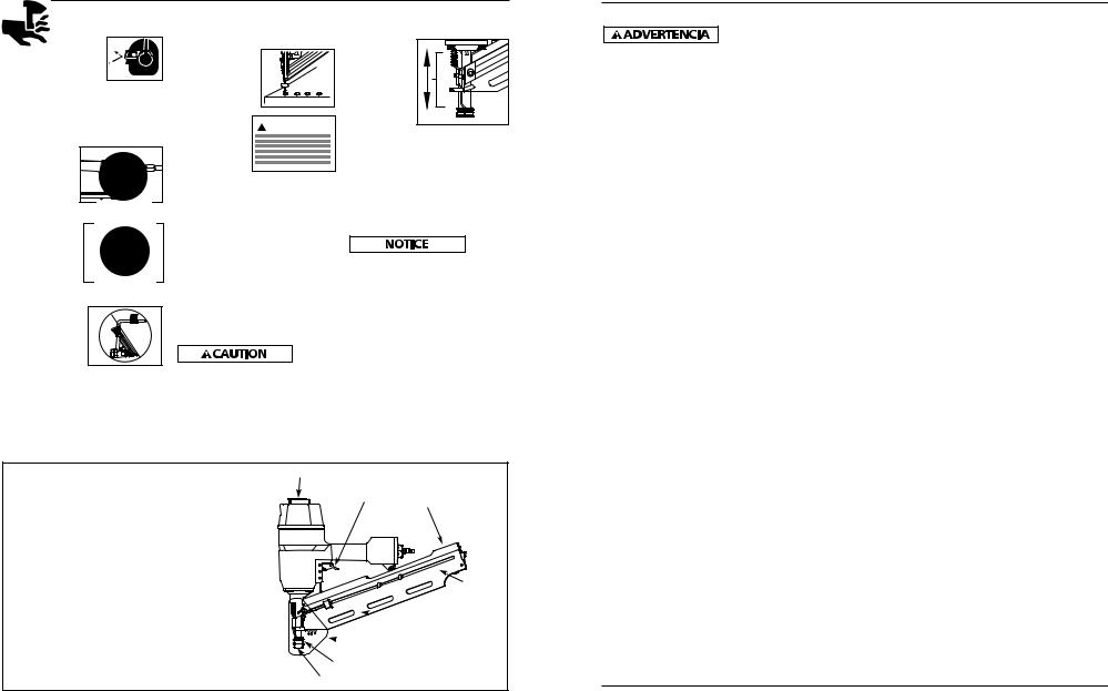
This nailer is designed for framing, trusses, sub-floors, sheathing, exterior decks, and pallet/create assembly. Features include: convenient top loading magazine, no-mar tip, adjustable exhaust, single cycle trigger, and an adjustable depth of drive mechanism.
General Safety Information
This manual contains safety, operational and maintenance information.
Read this manual and |
|
understand all safety |
|
warnings and instructions |
|
before operating the nailer. |
MANUAL |
CALIFORNIA PROPOSITION 65
You can create dust when you cut, sand, drill or grind materials such as wood,
paint, metal, concrete, cement, or other masonry. This dust often contains chemicals known to cause cancer, birth defects, or other reproductive harm.
Wear protective gear.
OPERATOR’S RESPONSIBILITY:
Before operating the nailer, read and understand all safety warnings and labels. Follow the operating instructions outlined in this manual.
EMPLOYER’S RESPONSIBILITY:
Distribute this instruction manual to all users before allowing use of the nailer.
Ensure all operators read, understand and follow all safety warnings, labels and instructions outlined in this manual.
Danger indicates
an imminently hazardous situation which, if not avoided, WILL result in death or serious injury.
● Do not use any type |
|
|
of flammable gases or |
|
|
oxygen as a power |
|
|
source for the nailer. |
O CO2 |
|
Use filtered, |
|
|
lubricated, regulated |
|
|
|
|
compressed air only. Use of a compressed gas instead of compressed air may cause the nailer to explode which will cause death or serious personal injury.
● Do not exceed |
|
maximum operating |
|
pressure of the nailer |
|
(120 psi). The nailer |
120 psi |
will not function |
|
properly. Do not use a |
MAX. |
|
compressed air source capable of more than 200 psi. The nailer could explode which will cause death or serious personal injury.
● Never use gasoline or
other flammable liquids to clean the nailer. Never use the
nailer in the presence
of flammable liquids or gases. Vapors could ignite by a spark and cause an explosion which will result in death or serious personal injury.
● Always remain in a firmly balanced position when using or handling the nailer.
● Do not modify or disable the Work
Contact Element (WCE). Do not tie or tape the WCE
or trigger in a depressed
position. Death or serious personal injury could result.
Locate model and date code on tool and record below:
Model No. ________________________
Date Code ________________________
Retain these numbers for future reference.
●Do not touch the trigger unless driving
nails. Never attach air line
to nailer or carry nailer while touching
the trigger. The
tool could eject a fastener which will result in death or serious personal injury.
Warning indicates
a potentially hazardous situation which, if not avoided, COULD result in death or serious injury.
● Always
disconnect nailer from air line before clearing jams, adjusting or
servicing the
nailer, relocating the nailer, or when the nailer is not in use. Always reconnect the air line BEFORE loading any fasteners.
This tool meets or exceeds Industries’ Standards as set forth by the American National Standard |
IN719600AV 4/07 |
Institute/International Staple, Nail and Tool Association in ANSI/ISANTA SNT-101-2002. |
|
24 Sp |
© 2007 |
|
Operating Instructions
The nailer could eject a fastener causing death or serious personal injury.
●Protect your eyes and ears. Wear Z87
safety glasses, with  side shields. Wear hearing protection. Employers and users are
responsible for ensuring the user or anyone near the nailer wears this safety protection. Serious eye injury or permanent hearing loss could result.
●Do not use a check valve or
any other fitting which
allows air to remain in the nailer. Death or
serious personal injury could occur.
●Never place hands or any other body parts in the nail discharge area of the nailer.
The nailer might
eject a fastener and could result in death or serious personal injury.
●Never carry the nailer by the air hose or pull the
hose to move the nailer or a
compressor. Keep hoses away from
heat, oil and sharp edges. Replace any hose that is damaged, weak or worn. Personal injury or tool damage could occur.
●Always assume the nailer contains nails. Never use the nailer as a toy.
Do not engage in horseplay. Always keep others at a safe distance from the work area in case of accidental
discharge of nails. Never point the nailer at anyone. Accidental triggering of the nailer could result in death or serious personal injury.
● Do not drive a
nail on top of other nails. The
nail could glance and cause death or a serious puncture wound.
● Do not operate or allow anyone
else to operate the nailer if any warnings or warning labels are not legible.
Warnings or warning labels are located on the nailer magazine and body.
●Never leave the nailer unattended or connected to an air compressor when not in use. Serious personal injury can occur if someone picks up and uses the nailer without knowing the correct way to operate the nailer.
●Do not drop or throw the tool. Dropping or throwing the tool can result in damage that will make the tool unusable or unsafe. If the tool has been dropped or thrown, examine the tool closely for bent, cracked or broken parts and air leaks. STOP and repair before using or serious injury could occur.
Caution indicates a potentially hazardous situation which,
if not avoided, MAY result in minor or moderate injury.
●Do not modify or alter the nailer or any nailer parts. Do not use the nailer if any shields or guards are removed or altered. Do not use the nailer as a hammer. Personal injury or tool damage may occur.
●Avoid long extended periods of work with the nailer. Stop using the nailer if you feel pain in hands or arms.
●Always check that the Work Contact Element (WCE) is operating
properly. A nail could
accidentally
be driven if the WCE is not working properly. Personal injury may occur (See "Checking the Work Contact Element" Section).
●Disconnect air supply and release tension from the pusher before attempting to clear jams because fasteners can be ejected from the front of the nailer. Personal injury may occur.
Notice indicates
important information, that if not followed, may cause damage to equipment.
●Avoid using the nailer when the magazine is empty. Accelerated wear on the nailer may occur.
●Clean and check all air supply hoses and fittings before connecting the nailer to an air supply. Replace any damaged or worn hoses or fittings. Tool performance or durability may be reduced.
●Air compressors providing air to the nailer should follow the requirements established by the American National Standards Institute Standard B19.3-1991; Safety Standard for Compressors for Process Industries. Contact your air compressor manufacturer for information.
Nailer Components And Specifications
• REQUIRES: |
4.1 SCFM with 16 fasteners |
|
per minute @ 90 psi |
• AIR INLET: |
1/4” NPT |
• NAIL LENGTH RANGE: |
2” to 31⁄2” |
• NAIL SHANK RANGE: |
0.113” to 0.131” |
• MAGAZINE CAPACITY: |
75 - 105 |
• WEIGHT: |
9 lbs., 2 oz. |
• LENGTH: |
18.50” |
• HEIGHT: |
15.00” |
• MAXIMUM PRESSURE: |
120 psi |
• PRESSURE RANGE: |
70 - 120 psi |
|
|
Adjustable Direction Exhaust Deflector
Trigger
Nail Loading Area
Magazine
 Warning Labels
(Backside)
 Debris Shield
Work Contact Element
Nail Discharge Area
Modelo HDN34901
Guía de Diagnóstico de Averías
Deje de usar la clavadora inmediatamente si alguno de los si guientes problemas ocurre. repuestos. Podría resultado le heridas graves. Cualquier reparación o reemplazo de piezas los
debe hacer un técnico calificado personal de un centro autorizado de servicio.
|
Problema |
|
Causa |
Solución |
|
|
|
|
|
|
|
|
|
|
Hay una fuga de aire en el |
|
Los anillos en O de la cubierta de la válvula del |
|
Debe reemplazar los anillos en O & chequear el |
|
|
área de la válvula del gatillo |
|
gatillo están dañados |
|
funcionamiento del elemento de funcionamiento al contacto |
|
|
|
|
|
|
|
|
|
Hay una fuga de aire entre la |
|
Los tornillos de la cubierta están flojos |
|
Debe apretar los tornillos |
|
|
cubierta y la boquilla |
|
|
|
|
|
|
|
|
Los anillos en O están dañados |
|
Debe reemplazar los anillos en O |
|
|
|
|
La defensa está dañada |
|
Debe reemplazar la defensa |
|
|
|
|
|
|
|
|
|
Hay una fuga de aire entre la |
|
Los tornillos están flojos |
|
Debe apretar los tornillos |
|
|
cubierta y la tapa |
|
|
|
|
|
|
|
|
El empaque está dañado |
|
Debe reemplazar el empaque |
|
|
|
|
|
|
|
|
|
La clavadora deja de clavar un |
|
La defensa está desgastada |
|
Debe reemplazar la defensa |
|
|
clavo |
|
|
|
|
|
|
|
|
La boquilla está sucia |
|
Debe limpiar el canal del sistema de impulso |
|
|
|
|
La suciedad o daños evitan el desplazamiento |
|
Debe limpiar el cargador |
|
|
|
|
libre de los clavos o el mecanismo de impulso en |
|
|
|
|
|
|
el cargador |
|
|
|
|
|
|
El resorte del mecanismo de impulso está dañado |
|
Debe reemplazar el resorte |
|
|
|
|
El flujo de aire hacia la clavadora es inadecuado |
|
Chequée las conexiones, la manguera o el compresor |
|
|
|
|
El anillo en O del pistón está desgastado o le |
|
Debe reemplazar los anillos en O. Lubríquelos. |
|
|
|
|
falta lubricación |
|
|
|
|
|
|
Los anillos en O de la válvula del gatillo están |
|
Debe reemplazar los anillos en O |
|
|
|
|
dañados |
|
|
|
|
|
|
Hay fugas de aire |
|
Debe apretar los tornillos y las conexiones |
|
|
|
|
Hay una fuga en el empaque de la tapa |
|
Debe reemplazar el empaque |
|
|
|
|
|
|
|
|
|
La clavadora funciona |
|
La clavadora no está bien lubricada |
|
Necesita lubricar la clavador |
|
|
lentamente o pierde su |
|
|
|
|
|
|
potencia |
|
El resorte de la tapa del cilindro está roto |
|
Debe reemplazar el resorte |
|
|
|
|
El orificio de salida de la tapa está obstruído |
|
Debe reemplazar las partes internas dañadas |
|
|
|
|
|
|
|
|
|
Hay clavos atascados en la |
|
La guía del mecanismo de impulso está desgastada |
|
Debe reemplazar la guía |
|
|
clavadora |
|
|
|
|
|
|
|
|
Los clavos no son del tamaño adecuado. |
|
Debe usar los clavos recomendados para esta clavadora |
|
|
|
|
Los clavos están doblados |
|
Reemplácelos con clavos en buenas condiciones |
|
|
|
|
Los tornillos del cargador o de la boquilla están flojos |
|
Debe apretar los tornillos |
|
|
|
|
El mecanismo de impulso está dañado |
|
Debe reemplazar el mecanismo de impulse de clavos |
|
|
|
|
|
|
|
|
2 |
23 Sp |
|
Manual de Instrucciones
ANTI DISPARO SIN CARGA
Los herramientas está equipada con una característica de anti disparo sin carga. Esto evita que se presione el WCE cuando sólo queden pocos clavos. Simplemente cargue nuevos clavos a continuación de los que quedan, para continuar disparando.
CÓMO AJUSTAR LA DIRECCIÓN DEL ESCAPE
Las clavadoras vienen con un deflector de escape de dirección ajustable. Esto
está diseñado Gire Rotate
para que el
usuario pueda cambiar la dirección del escape. Simplemente gire el deflector en cualquier dirección deseada.
CÓMO DESATASCAR LA CLAVADORA
1. Desconecte la clavadora del abastecimiento de aire.
2. Retire todos  los clavos del


 cargador


 (ver Cómo
 cargar o
Cómo
descargar). Si se ignora este paso, los clavos saldrán disparados por la parte frontal de la herramienta.
3.Inserte un desar-mador
en la nariz de la herramienta. Empuje la cuchilla del accionador para soltar el clavo atracado.
4.Sujete el clavo
atracado con unos alicates, y retírelo.
Servicio Técnico
Si desea hacer alguna pregunta referente a la reparación u operación de las clavadoras, sírvase llamar a nuestro número especial, 1-800-543-6400.
Clavos et Repuestos
Use solamente
partes de repuesto originales. Nunca substituya las partes. No use partes modificadas o partes que no den un rendimiento equivalente al equipo original. El rendimiento de las herramientas, la seguridad y la duración pueden verse reducidos.
Cuando ordene partes de repuesto o sujetadores, especifique el número de la parte.
Para reparar la clavadora
Las reparaciones de la clavadora las debe hacer SOLAMENTE un técnico calificado que tenga experiencia.
Para colocarle los sellos
Cada vez que repare una clavadora deberá limpiarle y lubricarle las partes internas. Le recomendamos que use Parker O-lube o un lubricante equivalente en todos los anillos en O. A cada anillo en O se le debe dar un baño de lubricante para anillos antes de instalarlos. Igualmente, deberá ponerle un poco de aceite a todas las piezas que se mueven y muñones. Finalmente, después de haberla ensamblado y antes de probar la herramienta deberá ponerle unas cuantas gotas de aceite sin detergente 30W u otro aceite similar, en las líneas de aire.
Sujetadores
La herramienta HDN34901 también coloca sujetadores diseñados para: Porter Cable FC 350A, Hitachi NR83AA2, Senco FramePro 701XP, 751XP , Ridgid R350CHA, DeWalt D51822, D51823 y Paslode F-3505.
22 Sp
Model HDN34901
Operating The Nailer
Read this manual and understand all safety warnings and instructions before operating the nailer.
LUBRICATION
This nailer requires lubrication before using the nailer for the first time and before each use. If an inline oiler is used, manual lubrication through the air inlet is not required on a daily basis.
The work surface
can become damaged by excessive lubrication. Proper lubrication is the owner’s responsibility. Failure to lubricate the nailer properly will dramatically shorten the life of the nailer and void your warranty.
1. Disconnect the air supply from the nailer to add lubricant.
2. Turn the nailer |
|
|
so the air inlet |
OIL |
|
is facing up. |
||
|
||
Place 4-5 drops |
|
|
of 30 W non- |
|
|
detergent oil |
|
|
into air inlet. |
|
|
Do not use |
|
|
detergent oils, oil additives, or air |
||
tool oils. Air tool oils contain |
||
solvents which will damage the |
||
nailer’s internal components. |
||
3. After adding oil, run nailer briefly. Wipe off any excess oil from the cap exhaust.
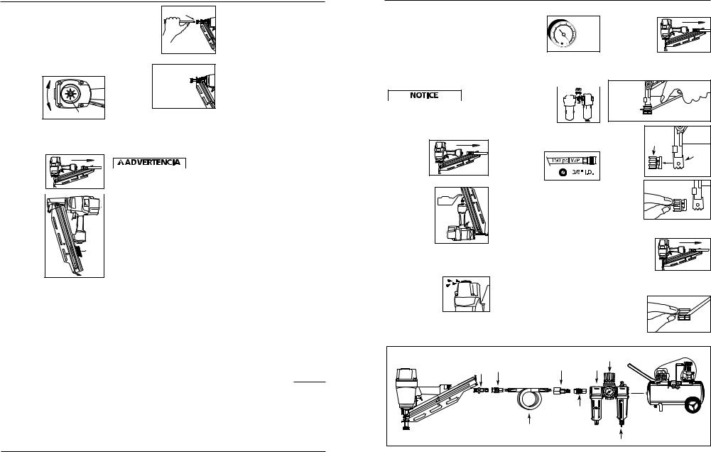
RECOMMENDED HOOKUP |
|
|
1. The air |
70 psi |
|
compressor |
||
Min. |
||
must be able |
120 psi |
|
to maintain a |
||
minimum of 70 |
Max. |
|
|
psi when the nailer is being used. An inadequate air supply can cause a loss of power and inconsistent driving.
2. An oiler can be  used to provide oil

 circulation through


 the nailer. A filter


 can be used to
 remove liquid and
solid impurities which can rust or “gum up” internal parts of the nailer.
3. Use 3/8” air
hoses with a minimum working
pressure of 150 psi. Use 1/2” air hoses for 50’ run or longer. For better performance, install a 3/8” quick plug (1/4” NPT threads) with an inside diameter of .315” (8mm) on the nailer and a 3/8” quick coupler on the air hose.
4.Use a pressure regulator on the compressor, with an operating pressure of 0 - 125 psi. A pressure regulator is required to control the operating pressure of the nailer between 70 and 120 psi.
NO-MAR DECKING TIP
The no-mar decking tip is designed to eliminate marks caused by the serrated work contact element (WCE). The nomar tip may be removed if not required (See REMOVING NO-MAR DECKING TIP). Use tool in single cycle mode (SEE OPERATIONAL MODES) when no-mar tip is in place.
REMOVING NO-MAR DECKING TIP
1. Disconnect air supply from nailer.
2.Remove all fasteners from magazine (See UNLOADING THE
NAILER).
3.Remove no-mar tip retaining ring.
Retaining
Ring 
 No-Mar Tip
4. Pry no- |
No- |
mar tip |
|
away |
Mar |
from the |
Tip |
|
|
work |
|
contact |
Work |
element. |
Contact |
|
Element |
5.Replace retaining
ring onto
no-mar
tip, then store tip in safe
place for future use.
INSTALLING NO-MAR DECKING TIP
1. Disconnect air supply from nailer.
2.Remove all fasteners from magazine (See UNLOADING THE NAILER).
3.Remove retaining ring from no-mar tip.
Recommended Hookup |
|
|
|
|
Quick |
Quick |
Quick Plug |
Regulator |
|
|
||||
(Optional) |
Oiler |
|||
Plug |
Coupler |
|||
|
|
Quick |
|
|
|
|
Coupler |
|
|
|
|
(Optional) |
|
|
|
|
Air |
|
|
|
|
Hose |
|
|
|
|
|
Filter |
|
|
|
3 |
|

Operating Instructions
4.Carefully place nomar tip
over the end of
work
contact Grooves element.

 Position
 tip onto
WCE
making certain serrated gooves on each piece are in line and fit snugly together.
5. Position retaining
ring on nomar tip and
press firmly in place.
6.Check that the WCE and trigger move up and down freely without sticking or binding.
Operational Modes
Always know the
operational mode of the nailer before using. Failure to know the operational mode could result in death or serious personal injury.
This stick framing nailer may be operated in the “Single Cycle” or the “Bottom Trip” mode. The nailer is delivered in the single cycle mode. A separate ‘red’ trigger for “Bottom Trip” mode is included with tool as an accessory.
SINGLE CYCLE MODE
When the black trigger is installed, nailer is in single cycle mode. This method is recommended when precise nail placement is required. Operation in this mode requires trigger to be pulled each time a nail is driven. Nailer can be actuated by depressing the Work Contact Element (WCE) against work surface followed by pulling the trigger.
The trigger must be released after each fastener is driven to allow tool to reset.
Since the tool can only be actuated by first removing the finger from the trigger, this is considered to be a more restrictive mode of operation, suitable for less experienced users.
BOTTOM TRIP MODE
When the red trigger is installed, the nailer is in bottom trip mode. This method is recommended when less precise nail placement is required. Operation in this mode requires trigger to be depressed with nailer off of the work surface. Then, the nose of the nailer is tapped against the work surface causing a nail to be driven.
Each time the Work Contact Element is depressed, a nail is driven into the work surface. Extreme care should be taken because a nail will be driven when the WCE is pressed against any surface.
Since the tool can be actuated without removing the finger from the trigger, this is considered to be a less restrictive mode, suitable for more experienced users.
MODE CONVERSION
To convert the tool from one mode to the other:
1.Remove o-ring on the side of trigger pin.
2.Remove trigger pin, trigger, and trigger spring.
3.Switch out only the trigger.
4.Replace trigger spring, trigger, trigger pin, and o-ring.
Do not attempt to modify the trigger components in any manner and do not attempt to use any other trigger components other than those intended for this tool.
Mode Conversion |
Trigger spring |
O-ring |
Trigger |
Trigger pin |
WORK CONTACT ELEMENT (WCE)
Check the
operation of the Work Contact Element
(WCE) trip mechanism before each use. The WCE must move freely without binding through its entire travel distance. The WCE spring must return the WCE to its fully extended position after being depressed. Do not operate the nailer if the WCE trip mechanism is not operating properly. Personal injury may occur.
1. Disconnect the air supply from the nailer.
2. Remove all nails from the magazine (see Unloading The Nailer).
3.Make sure the trigger and work contact element (WCE)
move freely up
and
down without sticking or binding.
4. Reconnect air supply to the nailer.
5.Depress the Work Contact
Element (WCE)
against the work surface without
pulling the trigger. The
nailer MUST NOT OPERATE. Do not use the tool if it operates without pulling the trigger. Personal injury may result.
|
|
|
|
|
|
|
|
Modelo HDN34901 |
|
4. |
Reconectar el |
|
CÓMO CARGAR LA CLAVADORA |
3. |
Sostenga la |
||||
|
abaste- |
|
1. |
Siempre conecte la herramienta al |
|
herramienta |
|||
|
cimiento de |
|
|
abastecimiento de aire antes de |
|
hacia arriba |
|||
|
aire a la |
|
|
cargar los sujetadores. |
|
|
para que los |
||
|
clavadora. |
|
2. |
Jale el |
|
|
|
clavos se |
|
|
|
|
El mecanismo |
El |
|
deslicen |
|||
|
|
|
|
mecanismo |
|
||||
5. |
Presione el |
|
|
del |
del |
enganche |
|
para atrás |
|
|
|
empujador |
|
|
hacia la |
||||
|
|
empujador |
|
|
|||||
|
elemento de |
|
|
de clavos |
|
|
ranura del |
||
|
|
|
de clavos |
|
|
||||
|
contacto de |
|
|
|
|
|
cargador. |
||
|
|
|
hasta que |
|
|
|
|||
|
trabajo (WCE) |
|
|
|
|
|
|
||
|
|
|
éste |
|
|
|
|
||
|
contra la |
|
|
|
|
|
|
||
|
superficie de |
|
|
engrane |
|
|
|
|
|
|
trabajo sin |
|
|
con el |
|
|
|
|
|
|
|
|
enganche |
|
|
|
|
||
|
tirar del |
|
|
|
|
4. |
Presione el |
||
|
gatillo. La |
|
|
del |
|
|
|||
|
|
|
|
|
|
empujador |
|||
|
clavadora |
|
|
cargador. |
|
|
|
||
|
|
|
|
|
|
con el |
|||
|
|
|
|
|
|
|
|||
|
NO DEBE |
|
3. |
Cargue la |
|
|
|
||
|
|
|
|
|
enganche |
||||
|
FUNCIONAR. |
|
|
tira de |
|
|
|
||
|
|
|
|
|
|
para desen− |
|||
|
No utilice la herramienta si ésta |
|
sujetadores |
|
|
|
|||
|
|
|
|
|
ganchar al |
||||
|
funciona sin haber tirado del gatillo. |
|
en la |
|
|
|
|||
|
|
|
|
|
empujador |
||||
|
Puede causar lesiones personales. |
|
ranura del |
|
|
|
|||
|
|
|
|
|
una vez que |
||||
6. |
Retire la |
|
|
cargador. |
|
|
|
||
|
|
|
|
|
se hayan |
||||
|
|
Asegúrese |
|
|
|
||||
|
clavadora |
|
|
|
|
|
retirado todos los clavos. |
||
|
|
|
de que los |
|
|
|
|||
|
de la |
|
|
|
|
CÓMO AJUSTAR LA PENETRACIÓN |
|||
|
|
|
clavos estén |
|
|
||||
|
superficie |
|
|
|
|
||||
|
de trabajo. |
|
|
colocados en la herramienta en la |
DEL CLAVO |
||||
|
El elemento |
|
|
orientación correcta. |
|
Las clavadoras NS219001 y HDN34901 |
|||
|
de contacto |
|
4. |
Presione el |
|
|
tienen una característica de |
||
|
de trabajo |
|
|
empujador |
|
|
profundidad de accionamiento |
||
|
(WCE) debe |
|
|
con el |
|
|
ajustable. Esto permite que el usuario |
||
|
regresar a |
|
|
enganche |
|
|
determine qué tan profundo se va a |
||
|
su posición |
|
|
para desen- |
|
|
introducir un clavo en la superficie de |
||
|
inferior |
|
|
ganchar al |
|
|
trabajo. |
||
|
original. Tire del gatillo. La |
|
|
empujador. |
|
|
1. Ajuste la presión de operación a una |
||
|
clavadora NO DEBE FUNCIONAR. |
|
Asegúrese |
|
|
|
presión que accionará |
||
|
No utilice la herramienta si ésta |
|
de que la |
|
|
|
uniformemente a los sujetadores. No |
||
|
funciona cuando se levanta de la |
|
cabeza del último clavo esté debajo |
|
exceda la máxima presión de |
||||
|
superficie de trabajo. Puede causar |
|
de la cabeza del empujador. |
|
operación de la clavadora de 8,27 bar. |
||||
|
lesiones personales. |
|
CÓMO DESCARGAR LA CLAVADORA |
2. Para ajustar la profundidad de |
|||||
7. Tire del gatillo y presione el elemento |
|||||||||
1. |
Siempre descargue todos los |
|
accionamiento, afloje el perno de 4 |
||||||
|
de contacto de trabajo (WCE) contra |
|
sujetadores antes de retirar la |
|
mm que está encima de la nariz. Para |
||||
|
la superficie de trabajo. La |
|
|
herramienta de funcionamiento. |
|
aumentar la profundidad, presione el |
|||
|
clavadora DEBE FUNCIONAR. |
|
La acción de descargar es lo |
|
elemento de contacto de trabajo |
||||
|
|
|
|
contrario a la de cargar, con la |
|
(WCE), hacia la nariz, tanto como lo |
|||
|
1 |
2 |
|
excepción que siempre debe |
|
desee. Vuelva a ajustar el perno. Para |
|||
|
|
|
|
desconectarse la manguera de |
|
disminuir la profundidad, retire el |
|||
|
|
|
|
aire antes de descargar. |
|
|
WCE tanto como desee. Vuelva a |
||
|
|
|
2. |
Jale el |
|
|
|
ajustar el perno. |
|
|
|
|
El mecanismo |
El |
3. |
Asegúrese |
|||
|
|
|
|
mecanismo |
|||||
|
|
|
|
del empu- |
del |
enganche |
|
de que el |
|
|
|
|
|
empujador |
|
|
|||
|
|
|
|
jador de |
|
|
gatillo y el |
||
|
|
|
|
de clavos |
|
|
|||
|
|
|
|
clavos hasta |
|
|
elemento |
||
8. Presione el elemento de contacto de |
|
que el |
|
|
|
de |
|||
|
empujador |
|
|
|
contacto |
||||
|
trabajo (WCE) contra la superficie de |
|
se engrane |
|
|
|
de trabajo |
||
|
trabajo. Tire del gatillo. La clavadora |
|
con el |
|
|
|
(WCE) se |
||
|
DEBE FUNCIONAR. |
|
|
enganche |
|
|
|
muevan |
|
|
|
|
|
del cargador. |
|
|
|
fácilmente |
|
|
1 |
2 |
|
|
|
|
|
hacia |
|
|
|
|
|
|
|
arriba y hacia abajo sin pegarse o |
|||
|
|
|
|
|
|
|
|
||
|
|
|
|
|
|
|
|
atracarse luego de cada ajuste. |
|
21 Sp
4
 Loading...