


Item # 911-625
Model # C602H
USE AND CARE GUIDE
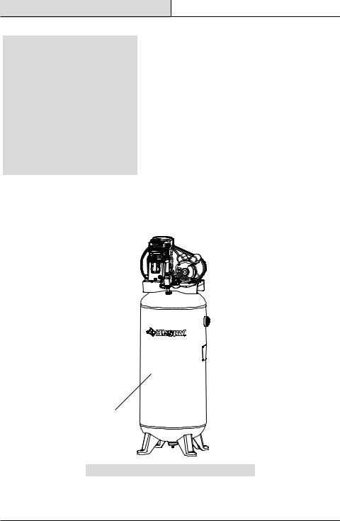
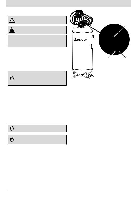
60-GALLON STATIONARY AIR COMPRESSOR
Questions, problems, missing parts? Before returning to the store, call Husky Customer Service
8 a.m. - 6 p.m., EST, Monday - Friday
1-888-43-HUSKY
HUSKYTOOLS.COM
C
THANK YOU
We appreciate the trust and confidence you have placed in Husky through the purchase of this air compressor. We strive to continually create quality products designed to enhance your home. Visit us online to see our full line of
products available for your home improvement needs. Thank you for choosing Husky!
Table of Contents
Safety Information.................................... |
2 |
System Components............................... |
9 |
Work Area Safety.................................... |
2 |
Placement of the Air Compressor......... |
10 |
Personal Safety ..................................... |
3 |
Air Distribution System......................... |
11 |
Moving the Compressor......................... |
3 |
Tool Usage............................................ |
13 |
Air Compressor and |
|
Breaking in the Pump........................... |
14 |
Pneumatic Tool Safety............................ |
4 |
Installation............................................... |
15 |
Electrical Safety..................................... |
5 |
Operation................................................. |
16 |
Warranty.................................................... |
7 |
Maintenance............................................ |
19 |
Pre-Operation............................................ |
8 |
Care and Cleaning................................... |
24 |
Specifications......................................... |
8 |
Troubleshooting....................................... |
25 |
Duty Cycle............................................... |
8 |
Service Parts .......................................... |
27 |
Package Contents................................... |
8 |
|
|
Safety Information
This manual contains information that is important for you to know and understand. This information relates to protecting your safety and preventing equipment problems. To help you recognize this information, we use the symbols below. Please read the manual and pay attention to these symbols.
DANGER: Indicates an imminently hazardous situation which, if not avoided, will result in death or serious injury.
WARNING: Indicates a potentially hazardous situation which, if not avoided, could result in death or serious injury.
CAUTION: Indicates a potentially hazardous situation which, if not avoided, may result in minor or moderate injury.
NOTICE: Indicates a practice not related to personal injury which, if not avoided, may result in property damage.
WORK AREA SAFETY
□□ Keep your work area clean and well lit. Ensure floors are not slippery from wax or dust.
□□ Operate the air compressor in an open area at least 18 in. (0.5 m) away from any wall or object that could restrict the flow of fresh air to ventilation openings.
WARNING: Do not operate power tools in explosive atmospheres, such as in the presence of flammable liquids, gases, or dust. Power tools create sparks which may ignite the dust or fumes. Keep bystanders, children, and visitors away while operating tools. Distractions can cause you to lose control.
WARNING: This compressor is not equipped for, and should not be used to supply breathing air. Additional equipment would be necessary to properly filter and purify the air to meet minimal specifications for Grade D breathing, as described in Compressed Gas Association Commodity, Specification G 7.1 - 1966, OSHA 29 CF9 1910.134. Compressed Gas Association, 4221 Walney
Road, Fifth Floor, Chantilly, VA 20151-2923, (703) 788-2700, www.cganet.com. Any such additional equipment has
not been examined and no implication of proper use for breathing air is intended or implied.
CAUTION: Always disconnect the air supply and power supply before making adjustments, servicing a tool, or when a tool is not in use.
2
Safety Information (continued)
PERSONAL SAFETY
□□ Keep proper footing and balance at all times. Proper footing and balance enables better control of the tool in unexpected situations.
□□ Do not use on a ladder or unstable support.
WARNING: Operating any power tool can result in foreign objects being thrown into your eyes, which can result in severe eye damage. Before beginning operation, always wear safety goggles, safety glasses with side shields, or
a full face shield when needed. Always use eye protection marked to comply with ANSI Z87.1.
WARNING: This product contains chemicals known to the State of California to cause cancer and birth defects or other reproductive harm. Wash hands after handling.
WARNING: Use safety equipment. Always wear eye protection with side shields when operating power tools. A dusk mask, non-skid safety shoes, hard hat, or hearing protection must be used for appropriate conditions.
WARNING: Stay alert when operating a power tool. Do not use the tool while tired or under the influence of drugs, alcohol, or medication.
WARNING: Do not wear loose clothing or jewelry. Contain long hair. Keep your hair, clothing, and gloves away from moving parts. Loose clothes, jewelry, or long hair can be caught in moving parts.
WARNING: Never touch any exposed metal parts on compressor during or immediately after operation. The compressor will remain hot for several minutes after operation. Do not reach around protective shrouds or attempt maintenance until the unit has been allowed to cool.
CAUTION: The compressor is too heavy to be lifted by one person. Obtain assistance from others before lifting.
MOVING THE AIR COMPRESSOR
□□ When transporting the compressor in a vehicle, trailer, etc., make sure the tank is drained and the unit is secured with straps to prevent tipping. Use care when driving to prevent tipping the unit over in the vehicle. Damage can occur to the compressor or surrounding items if the compressor is tipped. Always use two people when lifting and lift from the recommended lifting points.
WARNING: Risk of unsafe operation. Ensure proper footing and use caution when rolling the compressor so that the unit does not tip or cause loss of balance.
3 |
HUSKYTOOLS.com |
|
Please contact 1-888-43-HUSKY for further assistance. |

Safety Information (continued)
AIR COMPRESSOR AND PNEUMATIC TOOL SAFETY
□□ Keep compressors as far from the spraying area as possible: at least 15 ft. (4.6 m) from the spraying area and all explosive vapors.
□□ If connected to a circuit protected by fuses, use timedelay fuses with this product.
□□ Ensure the hose is free of obstructions or snags. Entangled or snarled hoses can cause loss of balance or footing, and may become damaged.
□□ Use the air compressor only for its intended use. Do not alter or modify the unit from the original design or function. Never weld or drill holes in the air tank.
□□ Never leave a tool unattended with the air hose attached.
□□ Do not operate this tool if it does not contain a legible warning label.
□□ Do not continue to use a tool or hose that leaks air or does not function properly.
□□ Do not attempt to pull or carry the air compressor by the hose.
□□ Your tool may require more air consumption than this air compressor is capable of providing.
□□ Never direct a jet of compressed air toward people or animals.
□□ Protect your lungs. Wear a face or dust mask if the operation is dusty.
□□ Do not use this air compressor to spray chemicals. Your lungs can be damaged by inhaling toxic fumes. A respirator may be necessary in dusty environments or when spraying paint.
□□ This compressor is equipped with a thermal overload protector which will shut off the motor if it becomes overheated.
WARNING: Do not attempt to modify this tool or create accessories not recommended for use with this tool. Any such alteration or modification is misuse and could
result in a hazardous condition leading to possible serious personal injury.
CAUTION: Do not use the compressor in an environment that is dusty or otherwise contaminated. Using the air compressor in this type of environment may cause damage to the unit.
CAUTION: Risk of bursting. Do not adjust the regulator to result in output pressure greater than the marked maximum pressure of the attachment. Do not use at pressure greater than the rated maximum pressure of this compressor.
CAUTION: To reduce the risk of electric shock, do not expose the compressor to rain. Store indoors.
4
Safety Information (continued)
ELECTRICAL SAFETY (EXTENSION CORDS)
□□ Use only 3-wire extension cords that have 3-prong grounding plugs and 3-pole receptacles that accept the product’s plug. Make sure your extension
cord is not damaged. When using a power tool at a considerable distance from the power source, use an extension cord heavy enough to carry the current that the product will draw. An undersized extension cord will cause a drop in line voltage, resulting in a loss of power and causing the motor to overheat.
□□ Use the chart provided below to determine the minimum wire size required in an extension cord. Only round jacketed cords listed by Underwriter’s Laboratories (UL) should be used.
□□ Only use 50 feet or less, round jacketed cords listed by Underwriter’s Laboratories (UL).
□□ When operating a power tool outside, use an outdoor extension cord marked “W-A” or “W”. These cords are rated for outdoor use and reduce the risk of electric shock.
|
Ampere rating |
|
|
(on air compressor data plate) |
|
|
14-16 |
|
|
|
|
Cord |
Wire Size (AWG) |
|
Length |
||
|
||
|
|
|
25 ft. |
16 |
|
|
|
|
50 ft. |
12 |
|
|
|
Used on 12 gauge - 20 amp circuit.
NOTE: AWG=American Wire Gauge
ELECTRICAL SAFETY (ELECTRICAL CONNECTION)
□□ This air compressor is powered by a precision built electric motor. It should be connected to a power supply that is 230 volts, 60 Hz, AC only (normal household current).
□□ Do not operate this tool on direct current (DC). A substantial voltage drop will cause a loss of power and the motor will overheat. If the air compressor does not operate when plugged into an outlet, double check the power supply.
WARNING: When using an extension cord, keep it clear of the working area. Position the cord so that it will not get caught on lumber, tools, or other obstructions while you are working with a power tool. Failure to do so can result in serious personal injury.
WARNING: Check extension cords before each use. If damaged, replace immediately. Never use the air compressor with a damaged cord since touching the damaged area could cause electrical shock resulting in serious personal injury.
WARNING: Improperly connecting the equipmentgrounding conductor can result in a risk of electrical shock.
CAUTION: Avoid body contact with grounded surfaces such as pipes, radiators, ranges, and refrigerators. There is an increased risk of electric shock if your body is grounded.
CAUTION: Do not expose power tools to rain or wet conditions. Water entering a power tool will increase the risk of electric shock.
CAUTION: Replace damaged cords/wiring immediately. Damaged cords/wiring increase the risk of electric shock.
NOTICE: Use longer air hoses instead of long extension cords. Your air compressor will run better and last longer.
5 |
HUSKYTOOLS.com |
|
Please contact 1-888-43-HUSKY for further assistance. |

Safety Information (continued)
ELECTRICAL SAFETY (SPEED AND WIRING)
□□ The no-load speed of this product is approximately 1,200 rpm. This speed is not constant and decreases under a load or with lower voltage.
□□ For voltage, the wiring in a shop is as important as the motor’s horsepower rating. A line intended only for lights cannot properly carry a power tool motor. Wire that is heavy enough for a short distance will be too light for a greater distance. A line that can support one power tool may not be able to support two or three products.
ELECTRICAL SAFETY (GROUNDING INSTRUCTIONS)
□□ This product must be connected to a grounded, metallic, permanent wiring system, or an equipment-grounding terminal or lead on the product.
6
Pre-Operation
SPECIFICATIONS
Running horsepower |
3.7 HP |
|
Air tank capacity |
60 gal. |
|
Air pressure |
155 PSI max. |
|
Air delivery |
13.4 SCFM at 40 PSI |
|
11.5 SCFM at 90 PSI |
||
|
||
|
|
|
Tank fill time |
7 minutes |
|
|
|
|
Lubrication |
Oil lube |
|
|
|
|
Input |
240V, 60 Hz, Single phase |
|
AC only, 13.5 Amps. |
||
|
||
Minimum branch circuit requirement |
20 A |
|
Fuse type |
Time delay |
|
|
|
|
Net weight |
218 lbs. |
|
|
|
DUTY CYCLE
This air compressor pump is capable of running continuously. However, to prolong the life of your air compressor, it is recommended that a 50% average duty cycle be maintained; that is, the air compressor pump should not run more than 30 minutes in any given hour.
PACKAGE CONTENTS
A
Pièce |
Description |
Quantity |
|
A |
Air Compressor Unit (fully |
1 |
|
assembled) |
|||
|
|
8
Pre-Operation (continued)
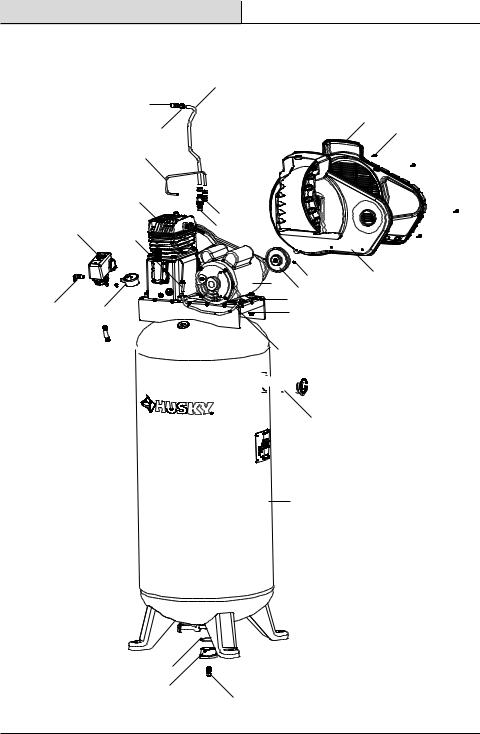
SYSTEM COMPONENTS |
K |
|
L |
I |
|
|
O |
|
E |
|
|
M |
|
A |
|
|
|
N |
|
G |
H |
P |
|
|
|
|
|
C |
|
|
B |
D |
|
|
J
F
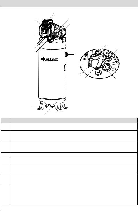
Part Description
AAUTO(I)/OFF(0) Switch: Turn this switch in the “Auto (I)” position to provide automatic power to the pressure switch and “Off (O)” to remove power at the end of each use.
Pressure Switch: The pressure switch automatically starts the motor when the air tank pressure drops
Bbelow the factory set “cut-in” pressure. It stops the motor when the air tank pressure reaches the factory set “cut-out” pressure.
Safety Valve: If the pressure switch does not shut off the air compressor at its “cut-out” pressure
Csetting, the safety valve will protect against high pressure by “popping out” at its factory set pressure (slightly higher than the pressure switch “cut-out” setting).
DTank Pressure Gauge: The tank pressure gauge indicates the reserve air pressure in the tank.
EAir Compressor Pump: Compresses air into the air tank. Working air is not available until the compressor has raised the air tank pressure above that required at the air outlet.
FDrain Valve: The drain valve is located at the base of the air tank and is used to drain condensation at the end of each use.
Check Valve: When the air compressor is operating, the check valve is “open”, allowing compressed air
Gto enter the air tank. When the air compressor reaches “cut-out” pressure, the check valve “closes”, allowing air pressure to remain inside the air tank.
Pressure Release Valve: The pressure release valve located on the side of the pressure switch, is designed to automatically release compressed air from the compressor head and the outlet tube when
Hthe air compressor reaches “cut-out” pressure or is shut off. The pressure release valve allows the motor to restart freely. When the motor stops running, air will be heard escaping from this valve for a few seconds. No air should be heard leaking when the motor is running or after the unit reaches “cut-out” pressure.
9 |
HUSKYTOOLS.com |
|
Please contact 1-888-43-HUSKY for further assistance. |
Pre-Operation (continued)
Part Description
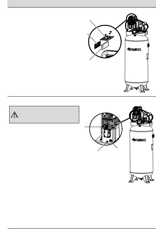
Thermal Overload Reset: This motor has a manual thermal overload protector. If the motor overheats for any reason, the overload protector will shut off the motor. The motor must be allowed to cool down before restarting. To restart:
I1. Place the AUTO/OFF switch in the “Off” position.
2.Allow the motor to cool.
3.Depress the red reset button on the motor.
4.Place the Auto/Off switch in the “Auto” postion to restart the motor.
JCompressor Feet: The compressor feet are used to stabilize the compressor and used as brackets when mounting to the floor.
KBelt Guard: The belt guard is a protective enclosure for moving parts.
LPump Oil Fill: The pump oil fill is used to add oil to the crankcase.
MPump Oil Drain: The pump oil drain is used to purge old oil from the pump. Loosening the drain plug will allow oil to exit the pump crankcase.
NPump Oil Sight Glass: The pump oil sight is a visual identifier for oil level in the crank case.
OMotor: The motor is the drive component powered by electricity to rotate the pump by a belt pulley system.
PAir Outlet: The air outlet is connection point to provide useable air for the tools.
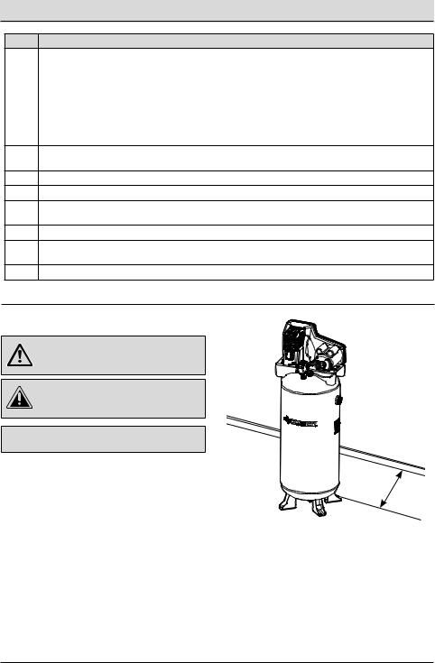
PLACEMENT OF THE AIR COMPRESSOR
WARNING: If any parts are damaged or missing do not operate this product until the parts are replaced. Failure to heed this warning could result in serious personal injury.
CAUTION: Do not use in an environment that is dusty or otherwise contaminated. Using the air compressor in this type of environment may cause damage to
the unit.
NOTICE: Long lengths of electrical wiring could cause power loss to the motor.
□□ Place the air compressor in a clean, dry, and well ventilated area.
□□ The air compressor must be positioned at least 18 in. (0.5 m) away from the wall or other obstructions that will interfere with the flow of air.
□□ Locate the air compressor as close to the main power supply as possible to avoid using long lengths of electrical wiring.
□□ The air filter must be kept clear of obstructions which could reduce the air flow to the air compressor.
18 in.
(0.5 m)
10

Pre-Operation (continued)
AIR DISTRIBUTION SYSTEM
The diagram on the following page represents a typical air distribution system. The following are tips to remember when setting up the air compressor’s air distribution system.
□□ Use a pipe that is the same size as the air tank outlet. Piping that is too small will restrict the flow of air.
□□ If the piping is over 100 ft. (30.5 m) long, use the next larger size.
□□ Bury underground lines below the frost line and avoid pockets where condensation can gather and freeze. Apply pressure before the underground lines are covered to make sure all the pipe joints are free of leaks.
□□ A flexible coupling is recommended to be installed between the globe valve/air discharge outlet and the main air distribution line to allow for vibration.
□□ A separate regulator is recommended to control the air pressure. Air pressure from the tank is usually too high for individual air driven tools.
□□ Do not install the lubricators between the tank and any spray equipment, air tool, or accessory requiring oil-free, filtered air.
□□ Drain all traps, filters, and dirt legs daily.
WARNING: Risk of bursting. Plastic or PVC pipe is not designed for use with compressed air. Regardless of its indicated pressure rating, plastic pipe can burst from air pressure. Use only metal pipe for air distribution lines.
WARNING: Risk of bursting. Always use metal piping and fittings.
NOTICE: Compressed air from the oil lube air compressors will contain water condensation and oil mist. Several drains, traps, and filters will be needed to supply air without water (including aerosols) or oil to the spray equipment, air tools, and accessories requiring filtered air. Always read the instructions for the air tools and accessories being used.
11 |
HUSKYTOOLS.com |
|
Please contact 1-888-43-HUSKY for further assistance. |

Pre-Operation (continued)
TYPICAL COMPRESSED AIR DISTRIBUTION SYSTEM
Part Description
ADrain Legs
BDrain Valves
CLubricator
DAir Tool
ERegulator
FFilter / Moisture Trap
GAir Usage Lines
HDirt Legs
I Air Discharge Valve
JFeeder Lines Slope with Air Flow
Main Distribution Air Lines - Slope pipe
Kin direction of air flow. Water condensate flows along bottom of pipe to drain legs, preventing it from entering feeder lines.
|
|
|
|
|
|
|
|
|
|
|
|
|
|
|
|
|
|
|
|
|
|
|
|
|
|
|
|
|
|
|
|
|
|
|
|
|
|
|
|
|
|
|
|
|
|
|
|
|
|
|
|
|
|
|
|
|
|
|
|
|
|
|
|
|
|
|
|
|
|
|
|
|
|
|
|
|
|
|
|
|
|
|
|
|
|
|
|
|
|
|
|
|
|
|
|
|
|
|
|
|
|
|
|
|
|
|
|
|
|
|
|
|
|
|
|
|
|
|
|
|
|
|
|
|
|
|
|
|
|
|
|
|
|
|
|
|
|
|
|
|
|
|
|
|
|
|
|
|
|
|
|
|
|
|
|
|
|
|
|
|
|
|
|
|
|
|
|
|
|
|
|
|
|
|
|
|
|
|
|
|
|
|
|
|
|
|
|
|
|
|
|
|
|
|
|
|
|
|
|
|
|
|
|
|
|
|
|
|
|
|
|
|
|
|
|
|
|
|
|
|
|
|
|
|
|
|
|
|
|
|
|
|
|
|
|
|
|
|
|
|
|
|
|
|
|
|
|
|
|
|
|
|
|
|
|
|
|
|
|
|
|
|
|
|
|
|
|
|
|
|
|
|
|
|
|
|
|
|
|
|
|
|
|
|
|
|
|
|
|
|
|
|
|
|
|
|
|
|
|
|
|
|
|
|
|
|
|
|
|
|
|
|
|
|
|
|
|
|
|
|
|
|
|
|
|
|
|
|
|
|
|
|
|
|
|
|
|
|
|
|
|
|
|
|
|
|
|
|
|
|
|
|
|
|
|
|
|
|
|
|
|
|
|
|
|
|
|
|
|
|
|
|
|
|
|
|
|
|
|
|
|
|
|
|
|
|
|
|
|
|
|
|
|
|
|
|
|
|
|
|
|
|
|
|
|
|
|
|
|
|
|
|
|
|
|
|
|
|
|
|
|
|
|
|
|
|
|
|
|
|
|
|
|
|
|
|
|
|
|
|
|
|
|
|
|
|
|
|
|
|
|
Part |
Description |
|
|
|
|
|
|
|
|
|
|
|
|
|||||||||||||||
|
|
|
|
|
|
|
|
|
|
|
|
|
|
|
|
|
|
|
|
|||||||||||||||||
|
|
|
|
|
|
|
|
|
|
|
|
|
|
|
|
|
|
|
|
|||||||||||||||||
|
|
|
|
|
|
|
|
|
|
|
|
|
|
|
|
|
|
|
|
|||||||||||||||||
|
|
|
|
|
|
|
|
|
|
|
|
|
|
|
|
|
|
|
|
|||||||||||||||||
|
|
|
|
|
|
|
|
|
|
|
L |
5 Micron Filter |
|
|
|
|
|
|
|
|
|
|
|
|
||||||||||||
|
|
|
|
|
|
|
|
|
|
|
|
|
|
|
|
|
|
|
|
|
|
|
|
|
||||||||||||
|
|
|
|
|
|
|
|
|
|
M |
.01 Micron Filter |
|
|
|
|
|
|
|
|
|
|
|
|
|||||||||||||
NSpray Gun
OBall Fitter
PFlexible Coupling
For Best Performance - The distance
Qbetween the compressor and the moisture trap should be as long as possible.
RAir Flow
12
Pre-Operation (continued)
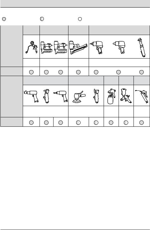
TOOL USAGE
= Continuous |
= Intermittent |
|
= Not Recommended |
|
|
|
|
|
|
Inflation |
Finishing nailing |
Framing/ |
Bolting |
|
Roofing |
||||
|
|
|
Tool
|
|
|
|
|
|
|
|
|
|
|
|
|
|
|
|
Brad |
|
|
|
|
|
Finished/Roof- |
Impact |
Heavy duty 1/2 in. and 3/4 |
|
||
Inflator |
|
|
Stapler |
Air ratchet |
|||||||||
nailer |
|
|
|
ing nailer |
Wrench |
in. impact wrench |
|||||||
|
|
|
|
|
|
|
|
|
|||||
Recommended |
|
|
|
|
|
|
|
|
Tool Use |
|
|
|
|
|
|
|
|
Cutting/Drilling |
|
Surface Prep |
Painting |
HVLP |
Grease |
|||
|
Painting |
Gun |
||||||
|
|
|
|
|
|
|||
Tool |
|
|
|
|
|
|
|
|
|
Cut off |
Drill/ |
|
|
|
|
|
|
Air hammer |
Impact |
Sander |
Grinder |
Paint gun |
Paint gun |
Grease Gun |
||
tool |
||||||||
|
driver |
|
|
|
|
|
||
|
|
|
|
|
|
|
||
Recommended |
|
|
|
|
|
|
|
|
Tool Usage |
|
|
|
|
|
|
|
|
13 |
HUSKYTOOLS.com |
Please contact 1-888-43-HUSKY for further assistance.
Pre-Operation (continued)
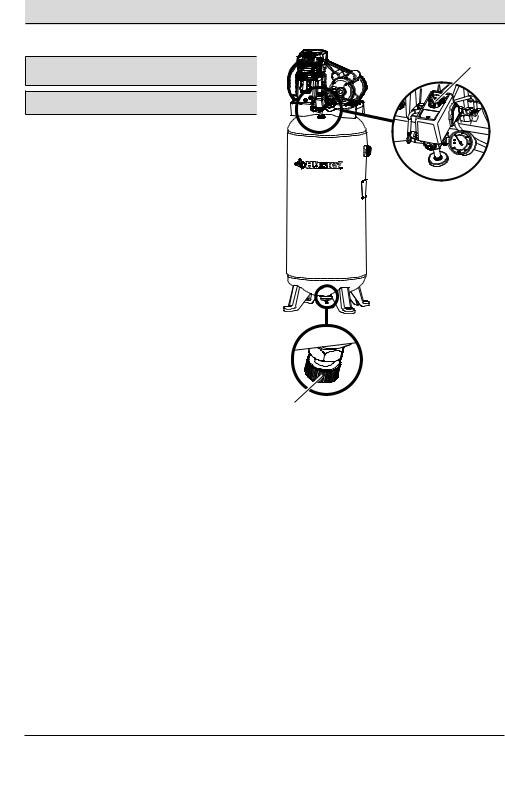
BREAKING IN THE PUMP
NOTICE: Risk of property damage. Serious damage may result if the |
1 |
following break-in instructions are not closely followed. |
|
NOTICE: Minor leaks can cause the air compressor to overwork, resulting in premature breakdown or inadequate performance.
This procedure is required before the air compressor is |
|
put into service and when the check valve or a complete |
|
compressor pump has been replaced. |
|
□□ Make sure the AUTO/OFF switch (1) is in the “Off” |
|
position. |
|
□□ Check oil level in the pump. See the Maintenance |
|
section for instructions. |
|
□□ Check all the wiring. Make sure the wires are |
|
secure at all terminals and connections. Make sure |
|
all contacts move freely and are not obstructed. |
|
□□ Open the drain valve (2) fully to permit air to escape |
|
and prevent air pressure build-up in the air tank |
|
during the break-in period. |
|
□□ Move the AUTO/OFF switch (1) to the “AUTO” |
|
position. The compressor will start. |
|
□□ Run the air compressor for 20 minutes. Make sure |
|
the drain valve and all air lines are open so there is |
|
only a minimal air pressure build-up in the tank. |
|
□□ Check all the air line fittings and connections/ |
2 |
|
|
piping for air leaks by applying a soap solution. |
|
Correct if necessary. |
|
□□ Check for excessive vibration. Readjust or shim the |
|
air compressor feet, if necessary. |
|
□□ After 20 minutes, close the drain valve (2). The air |
|
receiver will fill to “cut-out” pressure and the motor |
|
will stop. |
|
The air compressor is now ready for use. |
|
14
Installation
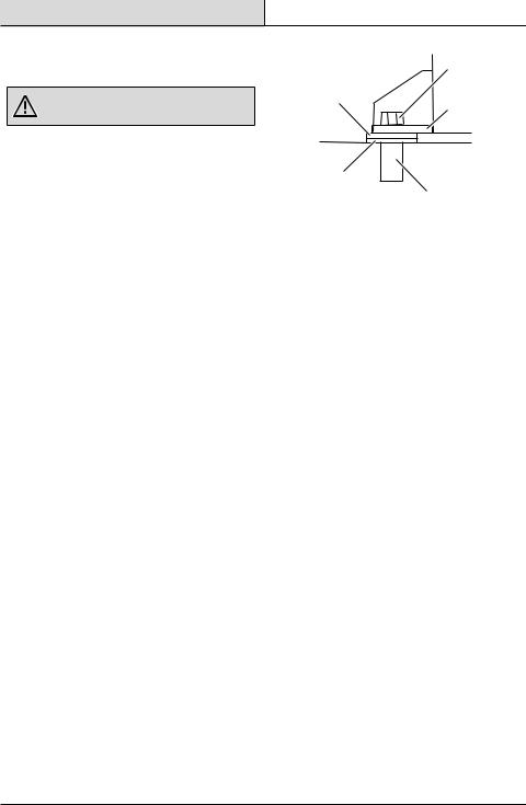
1 Anchoring of the air compresor
WARNING: Risk of bursting. Excessive vibration can weaken the air tank and cause an explosion. The compressor must be properly mounted.
The air compressor must be bolted to a level, solid concrete surface. Use the lag screws (CC), washers (AA), and concrete anchors (BB). If help is needed anchoring the air compressor, consult a licensed contractor.
□□ Place the air compressor on a level, solid concrete surface. Make sure the concrete is in good condition with no cracks or damage.
□□ Mark the surface using the holes in the air compressor feet (J) as a template.
□□ Drill holes in the surface for the concrete anchors. Install the concrete anchors (BB).
□□ Line-up the holes in the surface with the holes in the air compressor feet (J).
□□ Place the washers (AA) between the floor and the air compressor feet, as shown. If needed, use shims (DD) to level the unit.
□□ Place the lag screws (CC) through the air compressor feet (J), washers (AA), and into the anchors (BB).
□□ Torque the lag screws (CC) to 7-10 ft.-lbs (9.5-13.5 Nm).
|
CC |
AA |
J |
|
|
|
Surface Line |
DD |
|
|
BB |
15 |
HUSKYTOOLS.com |
|
Please contact 1-888-43-HUSKY for further assistance. |
Operation
1 |
Preparing for start-up |
1 |
|
||
|
|
|
|
WARNING: Risk of unsafe operation. Firmly grasp air |
|
|
hose in hand when installing or disconnecting to prevent |
|
|
hose whip. |
|
|
WARNING: Risk of unsafe operation. Do not use |
|
|
damaged or worn accessories. |
|
|
WARNING: Risk of bursting. Too much air pressure |
|
|
causes a hazardous risk of bursting. Check the |
|
|
manufacturer’s maximum pressure rating for air tools and |
|
|
accessories. The regulator outlet pressure must never |
|
|
exceed the maximum pressure rating. |
|
|
CAUTION: Risk of unsafe operation. Compressed air |
|
|
from the unit may contain water condensation and oil |
|
|
mist. Do not spray unfiltered air at an item that could be |
|
|
damaged by moisture. Some air tools and accessories may |
|
|
require filtered air. Read the instructions for the air tools |
|
|
and accessories. |
|
|
NOTE: A regulator MUST be installed when using |
|
|
accessories rated at less than 150 psi. The hose or |
|
|
accessory will require a quick connect plug if the air outlet |
|
|
is equipped with a quick connect socket. |
|
□□ Turn the AUTO ( I ) / OFF ( O ) switch (1) to the |
2 |
|
|
OFF ( O ) position. |
|
|
|
|
□□ Close the drain valve (2). |
|
|
□□ Visually inspect air lines and fittings for leaks. |
|
|
2 |
Starting the compressor |
1 |
|
||
WARNING: Risk of bursting. If any unusual noise or vibration is noticed, stop the air compressor immediately and have it checked by a trained service technician.
NOTE: When using the regulator and other accessories, refer to the manufacturer’s instructions.
□□ Plug the power cord into a proper receptacle.
□□ Turn the AUTO ( I ) / OFF ( O ) switch (1) to the AUTO ( I ) position, and allow the tank pressure to build. The motor will stop when the tank pressure reaches “cut-out” pressure.
2
16
Operation (continued)
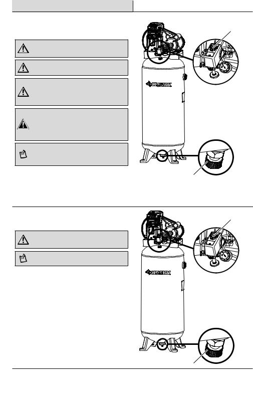
3 Checking the safety valve
DANGER: Do not tamper with the safety valve. Items loosened from this device could fly up and hit you. Failure to heed this warning could result in death or serious personal injury. The safety valve automatically releases air when the receiver pressure exceeds the preset maximum. Check the valve before each day of use by pulling the ring by hand.
WARNING: If air leaks after releasing the safety valve ring or if the valve is stuck, do not use the air compressor until the safety valve has been replaced. Using the air compressor in this condition could result in serious personal injury.
□□ Set the AUTO ( I ) / OFF ( O ) switch (1) to the on position, and wait for the tank to fill. The compressor automatically shuts off when the pressure reaches the preset maximum.
□□ Set the AUTO ( I ) / OFF ( O ) switch (1) to the off position.
□□ Pull the ring on the safety valve (2) for 20 seconds to release the air.
□□ Release the ring. Air stops escaping at about 20 psi. If air continues to escape after releasing the safety valve ring, discontinue use and seek service before using the air compressor again.
4 Running the air compressor
WARNING: Always ensure the switch is in the OFF position and using a regulator (not supplied) ensure pressure gauge reads zero before changing air tools or disconnecting the hose from the air outlet. Failure to do so could result in possible serious personal injury.
WARNING: Your tool may require more air consumption than this air compressor is capable of providing. Check tool manual to avoid damage to the tool or risk personal injury.
NOTE: Always use the minimum amount of air flow using a pressure regulator (not supplied). Using a higher pressure than needed will drain air from the tank more rapidly and cause the unit to cycle on more frequently.
□□ Never leave the unit plugged in and/or running unattended.
□□ When finished, always drain the tank and unplug the unit if applicable.
1
2
17 |
HUSKYTOOLS.com |
|
Please contact 1-888-43-HUSKY for further assistance. |
Operation (continued)
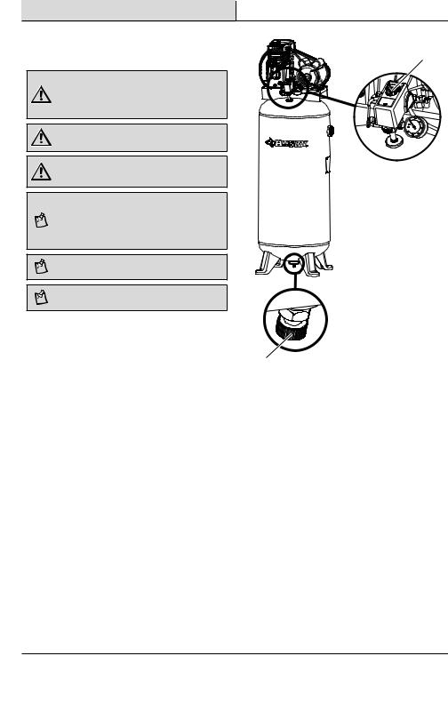
5 Draining the tank |
1 |
WARNING: Risk of unsafe operation. Air tanks contain |
|
high pressure air. Keep face and other body parts away |
|
from outlet of drain. Use eye protection [ANSI Z87.1 (CAN/ |
|
CSA Z94.3)] when draining, as debris can be kicked up |
|
into face. |
|
WARNING: Risk from noise. Use ear protection (ANSI |
|
S12.6 (S3.19), as air flow noise is loud when draining. |
|
WARNING: Risk of bursting. Water will condense in the |
|
air tank. If not drained, water will corrode and weaken the |
|
air tank causing a risk of air tank rupture. |
|
NOTE: All compressed air systems generate condensate |
|
that accumulates in any drain point (e.g., tanks, filter, |
|
after-coolers, dryers). This condensate contains lubricating |
|
oil and/or substances which may be regulated and must |
|
be disposed of in accordance with local, state, and federal |
|
laws and regulations. |
|
NOTE: If drain valve is plugged, release all air pressure. |
|
The valve can then be removed, cleaned, then reinstalled. |
|
NOTE: Risk of property damage. Drained water from the |
|
air tank may contain oil and rust which can cause stains. |
|
□□ Set the AUTO ( I ) / OFF ( O ) switch (1) to the OFF |
|
( O ) position. |
|
□□ Slowly bleed the air from the compressor |
2 |
tank by pulling the safety valve to allow the |
pressure to escape from the tank until the pressure is approximately 20 psi.
□□ Drain the water from the tank by opening the drain valve (2) on the bottom of the tank.
□□ After the water has been drained, close the drain valve (2). The air compressor can now be stored.
18

Maintenance
GENERAL MAINTENANCE
□□ Condensate forms in the tank when there is humidity in the air. Depending on the environmental conditions, drain the condensate daily and/or every hour. For instructions, see Draining the tank.
□□ The safety valve automatically releases air when the receiver pressure exceeds the preset maximum.
□□ Inspect the tank annually for rust, pin holes, or other imperfections that could cause it to become unsafe.
□□ Avoid using solvents when cleaning plastic parts. Most plastics are susceptible to damage from various types of commercial solvents and may be damaged by their use.
□□ Use clean cloths to remove dirt, dust, oil, grease, etc.
WARNING: When servicing, use only identical Husky replacement parts. Use of any other parts may create a hazard or cause product damage.
WARNING: Always release all pressure, disconnect from power supply, and allow unit to cool to the touch before cleaning or making repairs on the air compressor.
WARNING: Do not at any time let brake fluids, gasoline, petroleum-based products, penetrating oils, etc., come
in contact with plastic parts. Chemicals can damage, weaken or destroy plastic which may result in serious personal injury. Electric tools used on fiberglass material, wallboard, spackling compounds, or plaster are subject to accelerated wear and possible premature failure because the fiberglass chips and grindings are highly abrasive to bearings, brushes, commutators, etc. Consequently, we do not recommended using this tool for extended work on these types of materials. However, if you do work with any of these materials, it is extremely important to clean the tool using compressed air.
19 |
HUSKYTOOLS.com |
|
Please contact 1-888-43-HUSKY for further assistance. |
Maintenance (continued)
CHECKING THE OIL
WARNING: Drain the tank to release the air pressure before removing the oil fill cap or oil drain plug.
|
|
1 |
|
CAUTION: Overfilling with oil will cause premature air |
|
|
|
compressor failure. Do not overfill. |
|
|
|
NOTICE: Risk of property damage. Use air compressor oil only. |
|
|
|
Multi-weight automotive engine oils like 10W30 should not be |
|
|
|
use in the air compressors. They leave carbon deposits on critical |
|
|
|
components, thus reducing performance and compressor life. |
|
|
|
□□ The oil level should be to the middle of the sight |
|
|
|
glass (3). |
2 |
3 |
|
□□ If needed, remove the oil fill plug (1) and slowly |
|||
|
|
||
add the oil until it reaches the middle of the sight |
|
|
|
glass. |
|
|
NOTE: Use 30W compressor oil or a heavy duty SAE 30W, non-detergent, SF grade or better oil. Do not use multi-weight automotive engine oils, as they will reduce compressor life. Under extreme winter condition use SAE-10 weight oil.
CHANGING THE OIL
□□ Remove the oil fill plug (1).
□□ Remove the oil drain plug (2) and drain the oil into a suitable container.
□□ Replace the oil drain plug (2) and tighten securely.
□□ Slowly add the compressor oil until it reaches the middle of the sight glass (3).
NOTE: Crankcase oil capacity is approximately 10.6 fluid ounces (313,5 ml).
NOTE: When filling the crankcase, the oil flows very slowly into the pump. If the oil is added too quickly, it will overflow and appear to be full.
□□ Replace the oil fill plug (1) and tighten securely.
20
Maintenance (continued)
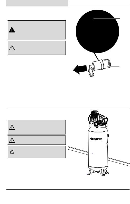
CLEANING THE AIR FILTER
From time to time, the air filter needs to be removed and cleaned.
□□ Turn the air compressor OFF ( O ). □□ Unplug the air compressor.
□□ Unsnap the air filter cover (1) to remove.
□□ Remove the air filter (2) from the air filter housing (3).
□□ Blow compressed air through the air filter for 10-15 seconds.
3
1
2
REPLACING THE BELT
WARNING: Serious injury or damage may occur if parts of the body or loose items get caught in moving parts. Never operate the outfit with the belt guard removed. The belt guard should be removed only when the air compressor power is disconnected.
□□ Turn the air compressor off, lock out the power |
L |
supply, and relieve all air pressure from the air |
|
tank. |
|
□□ Remove the four fasteners from the belt guard. |
|
The front belt guard can now be lifted up and |
|
away from the unit. |
N |
|
M |
□□ Mark the pump position on the saddle.
□□ Loosen the motor mounting screws and slide the motor toward the air compressor.
□□ Remove the belt and replace with a new one. □□ Mark the pump position on the saddle.
□□ See Adjusting the Belt Tension before tightening the motor mounting screws.
21 |
HUSKYTOOLS.com |
|
Please contact 1-888-43-HUSKY for further assistance. |
Maintenance (continued)
ADJUSTING THE BELT TENSION
NOTICE: Once the engine pulley has been moved from its factory set location, the grooves of the flywheel and pulley must be aligned to within 1/16 in. (1.6 mm) to prevent excessive belt wear. Verify the alignment by performing the MOTOR PULLY/FLYWEEL ALIGNMENT on the following page.
□□ Slide the motor into the original position, and line the motor up with the mark made earlier on the saddle.
□□ Tighten the two outside motor mounting screws enough to hold the motor in place for checking the pulley and flywheel alignment.
□□ The belt should deflect 3/16 in. (4.8 mm) at midway between the pulley and the flywheel when a five-pound (2.26 kg.) weight is applied at the midway point.
□□ When proper belt tension is achieved, tighten all four motor mounting screws. Torque to 20-25 ft-lbs (27.1–33.9 Nm).
 Downward Force
Deflection
22

Maintenance (continued)
MOTOR PULLEY/FLYWHEEL ALIGNMENT
The air compressor flywheel and motor pulley must be in-line (in the same plane) within 1/16 in. (1.6 mm) to assure belt retention within the flywheel belt grooves. To check the alignment, perform the following steps:
□□ Turn the air compressor off, lock out the power supply, and relieve all air pressure from the air tank.
□□ Remove belt guard.
□□ Place a straightedge (4) against the outside of the flywheel (1) and the motor drive pulley (3).
□□ Measure the distance between the edge of the belt (2) and the straightedge at points A1 and A2. The difference between measurements should be no more than 1/16 in. (1.6 mm).
□□ If the difference is greater than 1/16 in. (1.6 mm), loosen the set screw holding the motor drive pulley (3) to the shaft and adjust the pulley’s position on the shaft until the A1 and A2 measurements are within 1/16 in. (1.6 mm) of each other.
□□ Tighten the motor drive pulley set screw.
□□ Visually inspect the motor drive pulley to verify that it is perpendicular to the drive motor shaft. The points (B1 and B2) should appear to be equal. If they are not, loosen the setscrew of the motor drive pulley and equalize B1 and B2, using care not to disturb the belt alignment performed previously.
□□ Retighten the motor drive pulley setscrew. Torque to 145–165 in.-lbs. (16.4–20.3 Nm).
□□ Reinstall the belt guard.
|
1 |
2 |
|
|
|
|
|
3 |
|||
|
|
|
|
|
|
|
|
|
|
|
|
|
|
|
|
|
|
|
|
|
|
|
|
|
|
A1 |
|
A2 |
B1 |
|
B2 |
||||
|
|
|
|
|
|
|
|
|
|
||
|
|
A1= A2 (MEASURED) |
4 |
|
|
|
|||||
|
|
B1= B2 (VISUAL) |
|
|
|
|
|
||||
23 |
HUSKYTOOLS.com |
|
Please contact 1-888-43-HUSKY for further assistance. |

Maintenance (continued)
AIR COMPRESSOR INTAKE AND EXHAUST VALVES
Once a year bring the compressor to a service center and have a trained service technician check the air compressor pump intake and exhaust valves.
INSPECT AIR LINES AND FITTINGS FOR
LEAKS
NOTICE: Even minor leaks can cause the air compressor to overwork, resulting in premature breakdown or inadequate performance.
□□ Turn the air compressor off, lock out the power supply, and relieve all air pressure from the air tank.
□□ Apply a soap solution to all air line fittings and connections/piping.
□□ Correct any leaks found.
TORQUING THE AIR COMPRESSOR HEAD BOLTS
The air compressor pump head bolts should be kept properly torqued. Check the torques of the head bolts after the first five hours of operation.
□□ Torque to 14–16 ft. lbs. (19.0–21.7 Nm).
Care and Cleaning
□□ Drain the air tank of moisture after operation.
□□ When not in use, store the compressor in a cool, dry place.
□□ Disconnect the air hose and hang open ends down to allow any moisture to drain.
□□ Protect the electrical cord and air hose from damage (such as being stepped on or run over).
24

Troubleshooting
Problem |
Possible Cause |
Solution |
|
The compressor does not |
□□ The tank has insufficient |
□□ When the tank pressure drops, the |
|
run. |
pressure. |
compressor will turn on to cut-in |
|
|
|
pressure. |
|
|
|
|
|
|
□□ There is no eletrical power |
□□ Verify the wiring connection inside the |
|
|
to the unit. |
pressure switch and the terminal box |
|
|
|
area. |
|
|
|
|
|
|
□□ The circuit breaker has |
□□ Check the fuse/breaker to determine the |
|
|
tripped or a fuse has blown |
underlying cause. |
|
|
at the main power source. |
|
|
|
|
|
|
|
□□ The thermal overload |
□□ Turn the air compressor OFF ( O ). |
|
|
protector is actuated. |
|
|
|
□□ Wait until the compressor cools down. |
||
|
|
||
|
|
|
|
|
|
□□ Depress the red reset button on the |
|
|
|
motor. |
|
|
|
|
|
|
|
□□ Turn the air compressor to AUTO ( I ). |
|
|
|
|
|
|
□□ There is loss of power or |
□□ Verify the wiring. |
|
|
overheating. |
NOTE: Long lengths of electrical wiring |
|
|
|
could cause power loss to the motor. |
|
|
|
|
|
|
□□ The pressure switch is bad. |
□□ Replace the pressure switch. |
|
|
|
|
|
The motor hums while |
□□ There is low voltage from |
□□ Check the voltage with a voltmeter. |
|
running slowly, or it does not |
the power source. |
|
|
run at all. |
|
|
|
□□ There are loose eletrical |
□□ Verify the wiring connections inside the |
||
|
|||
|
connections. |
pressure switch and the terminal box |
|
|
|
area is secure. |
|
|
|
|
|
|
□□ There is a shorted or open |
□□ Bring the compressor to a service center. |
|
|
motor wiring. |
|
|
|
|
|
|
|
□□ There is a defective check |
□□ Bring the compressor to a service center. |
|
|
valve or unloader. |
|
|
|
|
|
|
The compressor is making |
□□ The compressor pump has |
□□ Check the pump oil. |
|
squealing sounds. |
no oil. |
|
|
|
|
|
|
|
□□ The belt is too loose. |
□□ Check the belt tension. |
|
|
|
|
|
The compressor is |
□□ The air filter is dirty. |
□□ Clean or replace the air filter. |
|
experiencing restricted air |
|
|
|
intake. |
|
|
25 |
HUSKYTOOLS.com |
|
Please contact 1-888-43-HUSKY for further assistance. |

Troubleshooting (continued)
Problem |
Possible Cause |
Solution |
||
The compressor is making |
□□ There is a loose pulley. |
□□ Tighten the pulley set screw. |
||
knocking sounds. |
|
|
|
|
□□ There is a loose flywheel. |
□□ Tighten the flywheel screw. |
|||
|
||||
|
|
|
|
|
|
□□ |
The compressor mounting |
□□ Tighten the mounting screws. |
|
|
|
screws are loose. |
|
|
|
|
|
||
|
□□ The belt is too loose. |
□□ Check the belt tension. |
||
|
|
|
||
|
□□ An excessive amount of |
□□ Bring the compressor to a service center. |
||
|
|
carbon has build-up in the |
|
|
|
|
pump. |
|
|
|
|
|
||
|
□□ The belt is too tight. |
□□ Check the belt tension. |
||
|
|
|
||
There is excessive belt wear. |
□□ The belt is too loose. |
□□ Check the belt tension. |
||
|
□□ The belt is too tight. |
□□ Check the belt tension. |
||
|
□□ The pully is loose. |
□□ Bring the compressor to a service center. |
||
|
□□ The pulley is misaligned. |
□□ Align the pulley/flywheel. |
||
There is oil and/or moisture |
□□ |
The connections (fittings, |
□□ Check all the connections with a soap |
|
in the tank and/or air lines. |
|
tubing, etc.) are loose and |
and water solution and tighten. |
|
|
|
leaking. |
|
|
|
|
|
||
|
□□ The drain valve is loose |
□□ Tighten the drain valve. |
||
|
|
or open. |
|
|
|
|
|
||
|
□□ The check valve is leaking. |
□□ Bring the compressor to a service center. |
||
|
|
|
|
|
There is excessive moisture |
□□ |
There is excessive water in |
□□ It is normal for oil lube air compressor |
|
in the discharge air. |
|
the air tank. |
pumps to release some oil into the tank |
|
|
|
|
and air lines. Air compressors will also |
|
|
□□ The oil blow-by has |
|||
|
generate water condensation that will |
|||
|
|
accumulated in the pump. |
||
|
|
form in the tank and air lines. Install |
||
|
|
|
||
|
|
|
water and oil filter traps when needed. |
|
|
|
|
The Typical Compressed Air Distribution |
|
|
|
|
System section provides a guideline. |
|
|
|
|
Contact or call Husky Customer Service |
|
|
|
|
for more information. |
|
|
|
|
|
|
|
|
|
□□ IMPORTANT: If the tank or air lines have |
|
|
|
|
excessive water and/or oil, bring the |
|
|
|
|
compressor to a service center. |
|
|
|
|
||
The fuses blow or the circuit |
□□ The incorrect fuse size is |
□□ Verify the proper fuse size is being used. |
||
breaker trips repeatedly. |
|
being used, or the circuit is |
|
|
|
|
overloading. |
|
|
|
|
|
|
|
|
|
|
□□ Use time-delay fuses. |
|
|
|
|
|
|
|
|
|
□□ Disconnect other electrical appliances |
|
|
|
|
from the circuit or operate the |
|
|
|
|
compressor on its own branch circuit. |
|
|
|
|
||
|
□□ There are loose eletrical |
□□ Verify the wiring connection inside the |
||
|
|
connections. |
pressure switch and the terminal box |
|
|
|
|
area. |
|
|
|
|
||
|
□□ There is a defective check |
□□ Bring the compressor to a service center. |
||
|
|
valve or unloader. |
|
|
|
|
|
|
|
|
|
|
|
|
26
Service Parts
C602H, AIR COMPRESSOR
17
14
|
1 |
15 |
2 |
|
|
18 |
|
|
|
13 |
|
|
|
|
20 |
|
16 |
|
|
|
3 |
19 |
|
|
|
|
|
|
|
|
|
|
|
|
24 |
5 |
4 |
|
|
|
108 |
|
|
22 |
23 |
|
|
|
|
|
|
11 |
|


 9 21
9 21


 12A
12A
12D
12
12D
12B
12C
27 |
HUSKYTOOLS.com |
|
Please contact 1-888-43-HUSKY for further assistance. |

Service Parts (continued)
Item Number |
Description |
Part Number |
|
|
|
1 |
Beltguard (Outer) |
E107832 |
|
|
|
2 |
#10 Plastite Screw |
NA |
|
|
|
3 |
Bolt, 5/16-18 x 1.25 Thr Form |
NA |
|
|
|
4 |
Beltguard (Inner) |
E107833 |
|
|
|
5 |
Setscrew |
NA |
|
|
|
6 |
Key 5MM x 20MM |
NA |
|
|
|
7 |
Belt 4L-520 "A" Section |
E107831 |
|
|
|
8 |
Pulley |
E105990 |
|
|
|
9 |
Cord Interconnect |
E105991 |
|
|
|
10 |
Bolt 5/16-18 x .75 |
NA |
|
|
|
11 |
Nut 5/16-18 UNC |
NA |
|
|
|
12 |
Tank Assembly Painted |
E107834 |
|
|
|
12A |
Bushing 2in. NPSM x 3/4in. NPTF |
E106539 |
|
|
|
12B |
Bushing 2in. NPSM x 1/4in. NPTF |
E105994 |
|
|
|
12C |
1/4in. NPT Drain Valve |
NA |
|
|
|
12D |
O-Ring 2in. |
E105995 |
|
|
|
13 |
Pump Assembly 755H |
E105996 |
|
|
|
14 |
Connector Male 1/4in. NPT x 3/8in. OD Tube |
E105997 |
|
|
|
15 |
3/8in. OD Tube Compression Nut Assembly |
E105998 |
|
|
|
16 |
1/4in. OD Tube Compression Nut Assembly |
E105999 |
|
|
|
17 |
Outlet Tube |
E107867 |
|
|
|
18 |
Pressure Relief Tube |
E106001 |
|
|
|
19 |
Check Valve 1/2in. NPT x 3/8in. OD Tube |
E106002 |
|
|
|
20 |
Pressure Switch |
E106003 |
|
|
|
21 |
Nipple 1/4in. NPT-18 x 2.00 |
NA |
|
|
|
22 |
Valve, Asme 175 PSI |
E106004 |
|
|
|
23 |
Gauge 300 PSI 1/4in. NPT Side Mount |
E106005 |
|
|
|
24 |
Motor |
E106006 |
|
|
|
24A |
Start Capacitor |
E106007 |
|
|
|
24B |
Run Capacitor |
E106008 |
|
|
|
24C |
Start Capacitor Cover |
E106009 |
|
|
|
24D |
Run Capacitor Cover |
E106010 |
|
|
|
25 |
Warning Label |
E106011 |
|
|
|
26 |
Hot Surface Warning Label |
E106012 |
|
|
|
NOTE: Any part number field without a number listed is not available. Descriptions are provided for reference only.
28

Questions, problems, missing parts? Before returning to the store call Husky Customer Service
8 a.m. - 6 p.m., EST, Monday-Friday
1-888-43-HUSKY
HUSKYTOOLS.COM
Retain this manual for future use.
Document Number: E107114
03/25/2014
 Loading...