

Page 1

HP ZBook 17 G6 Mobile Workstation
Maintenance and Service Guide
Page 2

© Copyright 2019 HP Development Company,
L.P.
AMD, AMD Radeon, and Enduro are trademarks
of Advanced Micro Devices, Inc. Bluetooth is a
trademark owned by its proprietor and used by
HP Inc. under license. Intel Core, Optane, Xeon,
XMM, vPro, and Thunderbolt are trademarks of
Intel Corporation or its subsidiaries in the U.S.
and/or other countries. Linux is the registered
trademark of Linus Torvalds in the U.S. and
other countries. Microsoft and Windows are
either registered trademarks or trademarks of
Microsoft Corporation in the United States
and/or other countries. NVIDIA and Quadro are
trademarks and/or registered trademarks of
NVIDIA Corporation in the U.S. and other
countries. Red Hat is a registered trademark of
Red Hat, Inc. in the United States and other
countries. DisplayPort and the DisplayPort logo
are trademarks owned by the Video Electronics
Standards Association (VESA) in the United
States and other countries.
The information contained herein is subject to
change without notice. The only warranties for
HP products and services are set forth in the
express warranty statements accompanying
such products and services. Nothing herein
should be construed as constituting an
additional warranty. HP shall not be liable for
technical or editorial errors or omissions
contained herein.
Product notice
This guide describes features that are common
to most models. Some features may not be
available on your computer.
Not all features are available in all editions or
versions of Windows. Systems may require
upgraded and/or separately purchased
hardware, drivers, software or BIOS update to
take full advantage of Windows functionality.
Windows 10 is automatically updated, which is
always enabled. ISP fees may apply and
additional requirements may apply over time
for updates. Go to http://www.microsoft.com
for details.
To access the latest user guides, go to
http://www.hp.com/support, and follow the
instructions to nd your product. Then select
User Guides.
Software terms
By installing, copying, downloading, or
otherwise using any software product
preinstalled on this computer, you agree to be
bound by the terms of the HP End User License
Agreement (EULA). If you do not accept these
license terms, your sole remedy is to return the
entire unused product (hardware and software)
within 14 days for a full refund subject to the
refund policy of your seller.
For any further information or to request a full
refund of the price of the computer, please
contact your seller.
First Edition: July 2019
Document Part Number: L73382-001
Page 3

Important Notice about Customer Self-Repair Parts
IMPORTANT: Your computer includes Customer Self-Repair parts and parts that should be accessed by only
an authorized service provider. See Chapter 5, "Removal and replacement procedures for Customer SelfRepair parts," for details. Accessing parts described in Chapter 6, "Removal and replacement procedures for
authorized service provider parts," can damage the computer or void your warranty.
iii
Page 4

iv Important Notice about Customer Self-Repair Parts
Page 5

Safety warning notice
WARNING! To reduce the possibility of heat-related injuries or of overheating the device, do not place the
device directly on your lap or obstruct the device air vents. Use the device only on a hard, at surface. Do not
allow another hard surface, such as an adjoining optional printer, or a soft surface, such as pillows or rugs or
clothing, to block airow. Also, do not allow the AC adapter to contact the skin or a soft surface, such as
pillows or rugs or clothing, during operation. The device and the AC adapter comply with the user-accessible
surface temperature limits dened by applicable safety standards.
v
Page 6

vi Safety warning notice
Page 7

Table of contents
1 Product description ....................................................................................................................................... 1
2 Components .................................................................................................................................................. 7
Right ....................................................................................................................................................................... 7
Left ......................................................................................................................................................................... 9
Display ................................................................................................................................................................. 10
Keyboard area ...................................................................................................................................................... 11
Touchpad settings ............................................................................................................................. 11
Lights ................................................................................................................................................. 13
Buttons, speakers, and ngerprint reader ........................................................................................ 14
Special keys ....................................................................................................................................... 15
Hot keys (select products only) ......................................................................................................... 16
Bottom ................................................................................................................................................................. 17
Cover .................................................................................................................................................................... 18
Rear ...................................................................................................................................................................... 18
Labels ................................................................................................................................................................... 19
Inserting a SIM card (select products only) ......................................................................................................... 20
3 Illustrated parts catalog .............................................................................................................................. 21
Computer major components .............................................................................................................................. 21
Display assembly subcomponents ...................................................................................................................... 25
Miscellaneous parts ............................................................................................................................................. 27
4 Removal and replacement procedures preliminary requirements .................................................................... 28
Tools required ...................................................................................................................................................... 28
Service considerations ......................................................................................................................................... 28
Plastic parts ....................................................................................................................................... 28
Cables and connectors ...................................................................................................................... 28
Drive handling ................................................................................................................................... 29
Workstation guidelines ..................................................................................................................... 29
Electrostatic discharge information .................................................................................................................... 29
Generating static electricity .............................................................................................................. 30
Preventing electrostatic damage to equipment ............................................................................... 30
Personal grounding methods and equipment .................................................................................. 31
Grounding the work area ................................................................................................................... 31
Recommended materials and equipment ........................................................................................ 31
vii
Page 8

Packaging and transporting guidelines .............................................................................................................. 32
5 Removal and replacement procedures for Customer Self-Repair parts ............................................................. 33
Component replacement procedures .................................................................................................................. 33
Preparation for disassembly ............................................................................................................. 33
Service door ....................................................................................................................................... 34
Battery ............................................................................................................................................... 35
Hard drive (HDD) ................................................................................................................................ 36
Solid-state drives (SSD) .................................................................................................................... 38
Optical drive ....................................................................................................................................... 39
Memory modules ............................................................................................................................... 41
SIM card ............................................................................................................................................. 43
WWAN module ................................................................................................................................... 44
Keyboard ........................................................................................................................................... 46
6 Removal and replacement procedures for authorized service provider parts .................................................... 50
Component replacement procedures .................................................................................................................. 50
Service door latch .............................................................................................................................. 51
Middle cover ...................................................................................................................................... 53
Fingerprint reader assembly ............................................................................................................. 55
Hard drive connector ......................................................................................................................... 56
Smart card board ............................................................................................................................... 57
NFC module ....................................................................................................................................... 58
Touchpad click board ......................................................................................................................... 59
Fans ................................................................................................................................................... 61
System board .................................................................................................................................... 63
Heat sink ............................................................................................................................................ 66
Discrete MXM graphics card .............................................................................................................. 68
Speaker .............................................................................................................................................. 70
Power button board .......................................................................................................................... 71
RTC battery ........................................................................................................................................ 72
Solid-state drive (SSD) ...................................................................................................................... 73
Memory modules ............................................................................................................................... 75
Display assembly ............................................................................................................................... 78
Top cover ........................................................................................................................................... 88
7 Troubleshooting guide ................................................................................................................................. 89
Resources ............................................................................................................................................................. 90
General troubleshooting steps ............................................................................................................................ 90
Identify the issue ............................................................................................................................... 91
viii
Page 9

1. Understand the issue .................................................................................................. 91
Boot up sequence ......................................................................................... 91
Failure classication ..................................................................................... 91
2. Examine the environment .......................................................................................... 93
3. Perform a visual inspection of hardware ................................................................... 94
4. Update BIOS and drivers ............................................................................................. 94
Manually updating BIOS and drivers ............................................................ 94
Remotely deploying BIOS and drivers .......................................................... 94
Analyze the issue ............................................................................................................................... 94
5. Remove or uninstall recently added hardware, software .......................................... 94
6. HP Hardware Diagnostics and Tools ........................................................................... 95
7. Status lights, blinking light codes, troubleshooting lights, and POST error
messages ........................................................................................................................ 96
Status lights .................................................................................................. 96
Blinking light codes ...................................................................................... 97
POST error messages ................................................................................... 97
Resolve the issue ............................................................................................................................... 98
8. Hard reset .................................................................................................................... 98
9. Soft reset (Default Settings) ....................................................................................... 99
10. Reseat cables and connections ................................................................................ 99
11. Test with minimum conguration .......................................................................... 100
Essential hardware conguration .............................................................. 100
Safe mode ................................................................................................... 101
12. Test with veried working conguration (hardware and/or operating system) ... 101
13. Replace the system board ...................................................................................... 101
Verify solution ................................................................................................................................. 102
Helpful Hints ...................................................................................................................................................... 102
At startup ........................................................................................................................................ 103
During operation ............................................................................................................................. 103
Consulting with HP Service ............................................................................................................. 104
Common issues and possible solutions ............................................................................................................ 104
Power-on issues .............................................................................................................................. 104
No Power ....................................................................................................................... 104
Intermittent power-on, shutdown, reboot ................................................................... 106
AC adapter issue ........................................................................................................... 107
Battery not recognized, not charging ........................................................................... 108
Battery discharges too fast .......................................................................................... 109
Burnt smell .................................................................................................................... 110
POST ................................................................................................................................................ 110
No video (with power) ................................................................................................... 110
Blinking lights ............................................................................................................... 111
ix
Page 10

Diagnostics error messages ......................................................................................... 112
BIOS password .............................................................................................................. 113
Performance (OS) ............................................................................................................................ 113
Intermittent shutdown ................................................................................................. 114
Blue screen .................................................................................................................... 115
Freeze at Windows Logo (hang/lockup) ....................................................................... 117
Electromagnetic Interference (EMI) .............................................................................. 118
No wake up .................................................................................................................... 119
Unresponsive ................................................................................................................ 120
Slow performance ......................................................................................................... 120
HP Smart Adapter warning message ........................................................................... 121
Incorrect time and date ................................................................................................ 121
Display ............................................................................................................................................. 122
Display anomalies ......................................................................................................... 122
Symptom .................................................................................................... 122
Quick check ................................................................................................. 123
HP PC Hardware Diagnostics (UEFI) for video test ..................................... 123
Display assembly diagram ......................................................................... 124
Dead pixel ..................................................................................................................... 124
No video (internal) ........................................................................................................ 124
No video (external) ....................................................................................................... 125
DisplayPort/VGA ........................................................................................................... 125
HDMI .............................................................................................................................. 125
No or bad external video via docking ........................................................................... 126
Incorrect or missing color/distorted image .................................................................. 126
Touch screen ................................................................................................................. 127
I/O devices ....................................................................................................................................... 128
Keyboard ....................................................................................................................... 128
Keyboard point stick ..................................................................................................... 129
Keyboard backlight ....................................................................................................... 129
Touchpad ....................................................................................................................... 130
Network Connectivity Ethernet (RJ-45 jack) ................................................................ 130
Network connectivity wireless (WLAN) ........................................................................ 131
WWAN ............................................................................................................................ 132
USB ................................................................................................................................ 133
Smart card reader ......................................................................................................... 134
Speaker, headphone - audio issues .............................................................................. 135
Thunderbolt (TB) ........................................................................................................... 136
Storage ............................................................................................................................................ 137
Hard drive/solid-state drive not recognized ................................................................ 138
No boot to operating system (no read/write error) ..................................................... 138
x
Page 11

Read-write error ........................................................................................................... 139
Slow performance ......................................................................................................... 139
Blue screen (BSOD) error .............................................................................................. 139
Noisy hard drive ............................................................................................................ 140
Mechanical ....................................................................................................................................... 141
Fan error message - 90B .............................................................................................. 141
Noise (sound) ................................................................................................................ 142
Fan runs constantly ...................................................................................................... 143
Thermal shutdown (hot) ............................................................................................... 144
Stuck power button ...................................................................................................... 144
Additional information ...................................................................................................................................... 145
Acronyms ......................................................................................................................................... 145
Blinking lights and boot error codes ............................................................................................... 146
Processor not executing code ...................................................................................... 146
BIOS recovery code unable to nd valid BIOS recovery image ..................................... 146
Memory module error ................................................................................................... 146
Graphics Controller Error (No Controller) ..................................................................... 147
Failure - System Board Error ........................................................................................ 147
Intel Trusted Execution Technology (TXT) Error .......................................................... 147
Sure Start unable to nd valid BIOS Boot Block image ................................................ 147
Sure Start has identied a problem (Manual Recovery Policy Set) .............................. 148
POST Error Messages and User Actions .......................................................................................... 148
Routine Maintenance for Performance Improvement .................................................................... 150
Common Blue Screen Error Messages ............................................................................................ 150
Error message list ......................................................................................................... 150
Bug check symbolic names ........................................................................................... 150
Microsoft general troubleshooting of Windows bug check codes ............................... 151
Use Windows Debugging Tool ......................................................................................................... 151
Windows Software Development Kit (SDK) .................................................................. 152
Display Issue: Pixel Anomalies ........................................................................................................ 156
Cable management ......................................................................................................................... 157
Connector types .............................................................................................................................. 158
8 Computer Setup (BIOS), TPM, and HP Sure Start ........................................................................................... 161
Using Computer Setup ....................................................................................................................................... 161
Starting Computer Setup ................................................................................................................ 161
Navigating and selecting in Computer Setup ................................................................................. 161
Restoring factory settings in Computer Setup ............................................................................... 161
Updating the BIOS ........................................................................................................................... 162
Determining the BIOS version ...................................................................................... 162
Downloading a BIOS update ......................................................................................... 162
xi
Page 12

Changing the boot order using the f9 prompt ................................................................................ 163
TPM BIOS settings (select products only) ......................................................................................................... 163
Using HP Sure Start (select products only) ....................................................................................................... 164
9 Backing up, restoring, and recovering ......................................................................................................... 165
Creating recovery media and backups .............................................................................................................. 165
Using HP Recovery media (select products only) ........................................................................... 165
Using Windows tools ....................................................................................................................... 166
Using the HP Cloud Recovery Download Tool (select products only) ............................................. 167
Restore and recovery ......................................................................................................................................... 167
Recovering using HP Recovery Manager ........................................................................................ 167
What you need to know before you get started ........................................................... 167
Using the HP Recovery partition (select products only) .............................................. 168
Using HP Recovery media to recover ............................................................................ 169
Changing the computer boot order .............................................................................. 169
Removing the HP Recovery partition (select products only) ....................................... 169
10 Using HP PC Hardware Diagnostics ............................................................................................................ 170
Using HP PC Hardware Diagnostics Windows (select products only) ............................................................... 170
Downloading HP PC Hardware Diagnostics Windows ..................................................................... 170
Downloading the latest HP PC Hardware Diagnostics Windows version ..................... 171
Downloading HP Hardware Diagnostics Windows by product name or number
(select products only) ................................................................................................... 171
Installing HP PC Hardware Diagnostics Windows ........................................................................... 171
Using HP PC Hardware Diagnostics UEFI ........................................................................................................... 171
Starting HP PC Hardware Diagnostics UEFI .................................................................................... 172
Downloading HP PC Hardware Diagnostics UEFI to a USB ash drive ............................................ 172
Downloading the latest HP PC Hardware Diagnostics UEFI version ............................ 172
Downloading HP PC Hardware Diagnostics UEFI by product name or number
(select products only) ................................................................................................... 172
Using Remote HP PC Hardware Diagnostics UEFI settings (select products only) ........................................... 173
Downloading Remote HP PC Hardware Diagnostics UEFI ............................................................... 173
Downloading the latest Remote HP PC Hardware Diagnostics UEFI version ............... 173
Downloading Remote HP PC Hardware Diagnostics UEFI by product name or
number .......................................................................................................................... 173
Customizing Remote HP PC Hardware Diagnostics UEFI settings .................................................. 173
11 Specications .......................................................................................................................................... 175
Computer specications .................................................................................................................................... 175
43.9 cm (17.3 in) display specications ............................................................................................................ 176
xii
Page 13

12 Power cord set requirements .................................................................................................................... 177
Requirements for all countries .......................................................................................................................... 177
Requirements for specic countries and regions ............................................................................................. 178
13 Statement of memory volatility ................................................................................................................ 180
Nonvolatile memory usage ............................................................................................................................... 182
Questions and answers ..................................................................................................................................... 184
Using HP Sure Start (select models only) .......................................................................................................... 185
14 Recycling ................................................................................................................................................ 186
Index ........................................................................................................................................................... 187
xiii
Page 14

xiv
Page 15

1 Product description
Category Description
Product Name HP ZBook 17 G6 Mobile Workstation
Processors 9th-generation Intel® Core™ processors
Intel Core i9-9880H (2.3 GHz, up to 4.8 GHz with Intel Turbo Boost Technology, 2666 MHz, octa-core, 16 MB L3
cache, 45 W)
Intel Core i7-9850H (2.6 GHz, up to 4.6 GHz with Intel Turbo Boost Technology, 2666 MHz, hexa-core, 12 MB L3
cache, 45 W)
Intel Core i7-9750H (2.6 GHz, up to 4.5 GHz with Intel Turbo Boost Technology, 2666 MHz, hexa-core, 12 MB L3
cache, 45 W)
Intel Core i5-9400H (2.5 GHz, up to 4.3 GHz with Intel Turbo Boost Technology, 2666 MHz, quad core, 8 MB L3
cache, 45 W)
Intel Core i5-9300H (2.4 GHz, up to 4.1 GHz with Intel Turbo Boost Technology, 2666 MHz, quad-core, 8 MB L3
cache, 45 W)
Intel® Xeon®, octa-core, BGA, processor
Intel Xeon E-2286M (2.4 GHz, up to 5.0 GHz with Intel Turbo Boost Technology, octa-core, 2666 MHz, 16 MB L3
cache, 45 W)
Graphics Integrated UMA graphics
Congure as UMA-only or use with hybrid when GPU congured on Core i5. Congure as hybrid-only when GPU
congured on Core i7 or Xeon processor.
● Core processors: Intel UHD graphics 630
● Xeon processors: Intel UHD graphics P630
Discrete graphics (select products only)
● Supports discrete only in BIOS
● NVIDIA® GC6 3.0 and GC OFF
● Hybrid (Switchable) Graphics
● NVIDIA Optimus™ Technology
● AMD® Enduro™ Technology
● Open GL 4.5/Open CL 1.2/Vulkan 1.0
● DisplayPort™ 1.4b with discrete (supported through Thunderbolt™ 3 and mini DisplayPort)
Supports up to four discrete displays or three UMA displays (through the optional docking station):
● NVIDIA Mosaic Technology
● AMD Eyenity
Supports the following graphics cards:
● NVIDIA Quadro™ T1000
1
Page 16

Category Description
● NVIDIA Quadro RTX 3000
● NVIDIA Quadro RTX 4000
● NVIDIA Quadro RTX 5000
Panel 39.6 cm (17.3 in), LED, 16:9 aspect ratio, display panel
Full high denition (FHD) (1920 × 1080), UWVA with ambient light sensor, antiglare, 300 nits, 72% sRGB, slim,
eDP, without camera
FHD, UWVA with ambient light sensor, antiglare, 300 nits, 72% sRGB, slim, eDP, with HD camera
FHD, UWVA with ambient light sensor, antiglare, 300 nits, 72% sRGB, slim, eDP, with FHD camera
Ultra high denition (UHD) (3840 × 2160), UWVA, touch with ambient light sensor, 400 nits, 95% sRGB, eDP
+PSR, with FHD camera and IR camera; not available with WWAN
UHD, RG phosphors + B-LED, UWVA DreamColor – 10 bit (8 + 2 dithering), antiglare, 400 nits, 100% DCI P3, with
HD camera
UHD, RG phosphors + B-LED, UWVA DreamColor – 10 bit (8 + 2 dithering), antiglare, 400 nits, 100% DCI P3, with
FHD and IR camera
Memory DDR4-2666 SODIMMs
Four memory module slots; two slots are customer accessible and upgradeable
Supports dual-channel memory
Supports up to 128 GB of system RAM in the following congurations:
● 131072 MB (32768 MB × 4)
● 65536 MB (32768 × 2 or 16384 MB × 4)
● 32768 MB (32768 × 1, 16384 MB × 2, or 8192 MB × 4)
● 16384 MB (16384 MB × 1, 8192 MB × 2, or 4096 MB × 4)
● 8192 MB (8192 MB × 1 or 4096 MB × 2)
ECC DDR4-2666 (Xeon processors only)
● 65536 MB (16384 MB × 4)
● 32768 MB (16384 MB × 2)
● 16384 MB (16384 MB × 1)
Primary storage M.2 (NGFF) SS/DS solid-state drives (2280)
512 GB, SATA-3, TLC, FIPS-140-2
256 GB, PCIe, NVMe, TLC
512 GB, PCIe, NVMe, TLC
512 GB, PCIe, NVMe, TLC, Opal 2
1 TB, PCIe, NVMe, TLC
2 TB, PCIe, NVMe, TLC
Secondary storage M.2 solid-state drives (2280) (only available if primary M.2 is selected)
512 GB, SATA-3, TLC, FIPS-140-2
2 Chapter 1 Product description
Page 17

Category Description
256 GB, PCIe, NVMe, TLC
512 GB, PCIe, NVMe, TLC
512 GB, PCIe, NVMe, TLC, Opal 2
1 TB, PCIe, NVMe, TLC
2 TB, PCIe, NVMe, TLC
Third M.2 storage M.2 solid-state drives (2280) (only available if primary M.2 and secondary M.2 are selected)
512 GB, SATA-3, TLC
256 GB, PCIe, NVMe, TLC
512 GB, PCIe, NVMe, TLC
512 GB, PCIe, NVMe, TLC, Opal 2
1 TB, PCIe, NVMe, TLC
2 TB, PCIe, NVMe, TLC
Primary 2.5 inch
SATA storage
Fixed optical drive 9.0 mm SATA (supports E-SATA and drive inserts; select products only)
RAID NVMe RAID (only available if 1 TB M.2 + 1 TB 2nd M.2 or 2 TB M.2 + 2 TB 2nd M.2 are selected)
Flash cache 16 GB Intel Optane™ cache, only available if HDD (except FIPS or SED) and Windows® 10 is selected and M.2
Audio and video HP Bang & Olufsen Audio
Hard drive, 2.5 inch, 7 mm/9.5 mm (primary 2.5 inch storage is not a required category if M.2 solid-state drive
is selected)
2 TB, 5400 rpm
1 TB, 7200 rpm
500 GB, 7200 rpm Self Encrypting Drive (SED, FIPS-140-2)
500 GB, 7200 rpm
Solid-state drive, 2.5 inch
256 GB, SATA, TLC
1 TB, SATA, TLC
Blu-ray R/RE DVD +/-RW SuperMulti DL Drive
Optical drive with 2 TB, 5400 rpm hard drive (includes cradle)
Supports secondary drive (M.2 via SATA 2.5 inch bay)
storage is available
HP Noise Cancellation Software
HP Clear Sound amp
Discrete amp
Skype for Business Certication
Intel SST Audio
Dual array and rear-facing microphones
3
Page 18

Category Description
Stereo speakers (2)
Webcam HD 720p
Webcam FHD + IR RGB
Camera privacy cover (only with non-touch camera panels)
Support for models without camera
RJ-45 (network) Intel Ethernet Connection I219-LM 10/100/1000 (vPro)
Intel Ethernet Connection I219-V 10/100/1000 (non-vPro)
Wireless networking Bluetooth® 5.0
Wireless local area network (WLAN) with dual antennas (M.2 12 × 16 soldered down PCIe/USB; select
products only)
● Intel Wi-Fi 6 AX200 + Bluetooth 5 (802.11ax 2 × 2 vPro, supporting gigabit transfer speeds)
● Intel Wi-Fi 6 AX200 + Bluetooth 5 (802.11ax 2 × 2 non-vPro, supporting gigabit transfer speeds)
Two WLAN antennas built into top of display assembly
Compatible with Wi-Fi CERTIFIED Miracast™ devices
Support WoWLAN S3/S4
Support HP LAN-Wireless Protection (WLAN/LAN/WWAN switching)
Support HP Connection Optimizer
Support Fast PCIe Error Identication
Support Turbo Lite Wi-Fi
Near-Field Communication (NFC) (select products only)
NXP NPC300 Near Field Communication Module (NFC Mirage XRAV-1 [NXP NPC300 I2C 10 mm x 17 mm])
NFC antenna
Wireless wide area network (WWAN) (M.2 30 × 42 socket, select products only)
Integrated wireless wide area network (WWAN) options by way of wireless module, SIM Module (3FF/micro SIM)
(user accessible behind battery)
Two WWAN antennas (worldwide 5 band, congured at top of display panel)
Supports the following WWAN format:
● Intel XMM™ 7360 LTE-Advanced (CAT 9)
Support for WWAN aftermarket option (AMO)
Media card reader microSD media reader slot supports SD™, SDHC™, and SDXC™
Ports Two Intel USB 3.1 Gen 2 + pass through DisplayPort 1.4 support with discrete, 1.2 with UMA support +
Thunderbolt 3 with PD, supported with BC 1.2
USB 3.1 port
USB 3.1 charging port (S3/S5)
HDMI 2.0b (models with discrete graphics), HDMI 1.4 (models with UMA graphics)
4 Chapter 1 Product description
Page 19

Category Description
Mini DisplayPort 1.4 (models with discrete graphics, mini-DisplayPort 1.2 (models with UMA graphics)
RJ-45 (network)
Audio-out (headphone)/audio-in (microphone) combo jack
Multiple pin AC port
Docking HP Thunderbolt Dock 120W G2
HP Thunderbolt Docking Station
HP USB-C/A Universal Dock G2
HP Elite USB-C Dock G5
Keyboard/pointing
devices
Power requirements Battery
Keyboard
Full sized Chiclet (island-style) keyboard with separate numeric keypad (backlit and non-backlit)
Windows 10 dual point (3-pick button pointing stick and 3-pick buttons on touchpad)
Touchpad
On/o button
Glass with chemical etched surface
Supports 2-way scroll, taps enabled by default, image sensor
Gestures enabled by default: 2-nger scrolling, 2-nger zoom (pinch)
Image sensor touchpad
DreamColor calibrator, built in under the touchpad
HP Long Life Polymer Soft Pack Battery, 6 cell, 95.6 Wh, 4.15 Ah
HP Fast Charge Technology
AC adapter
200 W slim Smart AC Adapter
Power cord
3-wire plug (C13), 1.0 m
Security Security lock
Trusted Platform Module (TPM) 2.0 (Inneon, soldered down)
Touch ngerprint sensor (select products only)
Hardware-enforced rmware protection: HP Hardware Root of Trust + Sure Start Gen 4
Smart Card reader (active)
Preboot authentication (password, smart card, ngerprint)
Drive Encryption preboot option (password, ngerprint, smart card)
Operating system Preinstalled
Windows 10 Home 64 Advanced
5
Page 20

Category Description
Windows 10 Home 64 Advanced Single Language
Windows 10 Home 64 High-end Chinese Market
Windows 10 Home 64 Plus
Windows 10 Home 64 Plus Single Language
Windows 10 Professional 64
Windows 10 Professional 64 Chinese Market
Windows 10 Professional 64 High End
Windows 10 Professional 64 High End Chinese Market
Windows 10 Professional 64 for Workstations Plus
Windows 10 Professional 64 for Workstations Plus Chinese Market
FreeDOS 3.0
Web only support
Windows 10 Enterprise 64
Windows 10 Pro 64 CBB 1803
Ubuntu 18.04 LTS
Red Hat® Enterprise Linux® 8
Red Hat Enterprise Linux 7 Workstation
Drop-in-box
Red Hat Enterprise
Restore Media
Windows 10 DRDVD, available with any Windows 10 operating system
Windows 10 Pro 64 OSDVD
Certied
Microsoft® WHQL
Serviceability End user replaceable parts
AC adapter
Battery
Solid-state drive
Hard drive
Keyboard
Memory module
Optical drive
WWAN module
6 Chapter 1 Product description
Page 21
2 Components
Your computer features top-rated components. This chapter provides details about your components, where
they are located, and how they work.
NOTE: Actual computer color, features, feature locations, and icon labels may vary from the images
depicted.
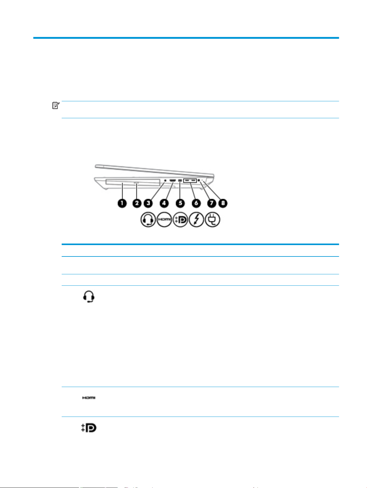
Right
Table 2-1 Right-side components and their descriptions
Component Description
(1) Optical drive Depending on your computer model, reads an optical disc or
reads and writes to an optical disc.
(2) Optical drive eject button Releases the optical drive disc tray.
(3) Audio-out (headphone)/Audio-in (microphone)
combo jack
(4) HDMI port Connects an optional video or audio device, such as a high-
Connects optional powered stereo speakers, headphones,
earbuds, a headset, or a television audio cable. Also connects an
optional headset microphone. This jack does not support
optional standalone microphones.
WARNING! To reduce the risk of personal injury, adjust the
volume before putting on headphones, earbuds, or a headset.
For additional safety information, see the Regulatory, Safety,
and Environmental Notices.
To access this guide:
▲ Type HP Documentation in the taskbar search box,
and then select HP Documentation.
NOTE: When a device is connected to the jack, the computer
speakers are disabled.
denition television, any compatible digital or audio
component, or a high-speed High Denition Multimedia
Interface (HDMI) device.
(5) Mini Dual-Mode DisplayPort connector Connects an optional digital display device, such as a high-
performance monitor or projector.
Right 7
Page 22

Table 2-1 Right-side components and their descriptions (continued)
Component Description
NOTE: When you have devices connected to the Mini Dual-
Mode DisplayPort and the HDMI port at the same time, the
image will be displayed only on the device connected to the
HDMI port.
(6) USB Type-C Thunderbolt ports with HP Sleep
and Charge (2)
(7) Power connector Connects an AC adapter.
(8) Battery light When AC power is connected:
Even when the computer is o, connect and charge most USB
devices that have a Type-C connector, such as a cell phone,
camera, activity tracker, or smartwatch, and provide high-speed
data transfer.
– and –
Connect display devices that have a USB Type-C connector,
providing DisplayPort output.
NOTE: Your computer may also support a Thunderbolt
docking station.
NOTE: Cables and/or adapters (purchased separately) may be
required.
● White: The battery charge is greater than 90 percent.
● Amber: The battery charge is from 0 to 90 percent.
● O: The battery is not charging.
When AC power is disconnected (battery not charging):
● Blinking amber: The battery has reached a low battery
level. When the battery has reached a critical battery level,
the battery light begins blinking rapidly.
● O: The battery is not charging.
8 Chapter 2 Components
Page 23
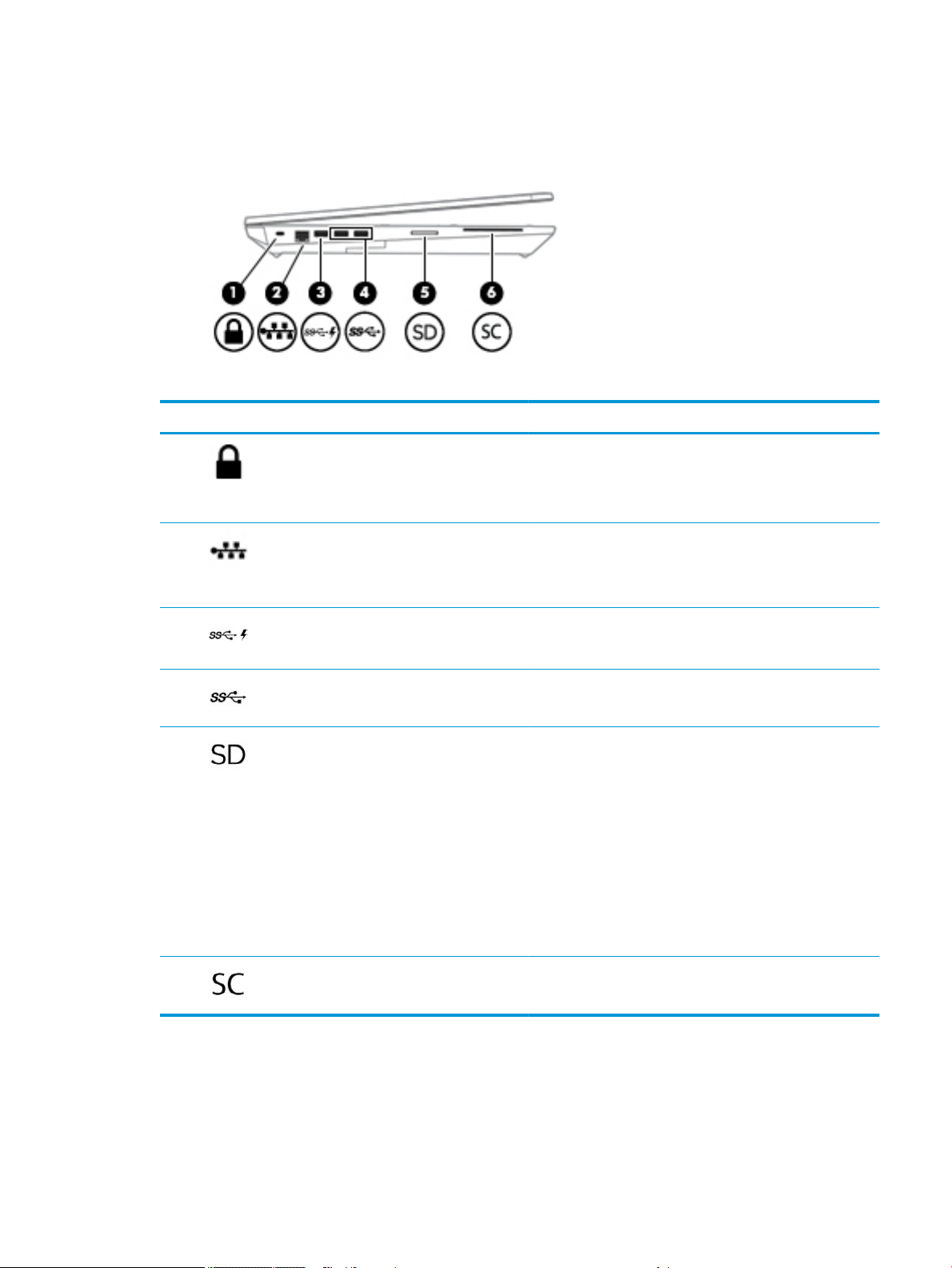
Left
Table 2-2 Left-side components and their descriptions
Component Description
(1) Security cable slot Attaches an optional security cable to the computer.
NOTE: The security cable is designed to act as a deterrent, but
it may not prevent the computer from being mishandled or
stolen.
(2) RJ-45 (network) jack/status lights Connects a network cable.
● Green (left): The network is connected.
● Amber (right): Activity is occurring on the network.
(3) USB SuperSpeed port with HP Sleep and Charge Connects a USB device, provides high-speed data transfer, and
even when the computer is o, charges most products such as a
cell phone, camera, activity tracker, or smartwatch.
(4) USB SuperSpeed ports (2) Connect USB devices, such as a cell phone, camera, activity
tracker, or smartwatch, and provide high-speed data transfer.
(5) Memory card reader Reads optional memory cards that store, manage, share, or
access information.
To insert a card:
1. Hold the card label-side up, with the connectors facing the
computer.
2. Insert the card into the memory card reader, and then
press in on the card until it is rmly seated.
To remove a card:
▲ Press in on the card, and then remove it from the memory
card reader.
(6) Smart card reader Supports optional smart cards.
Left 9
Page 24
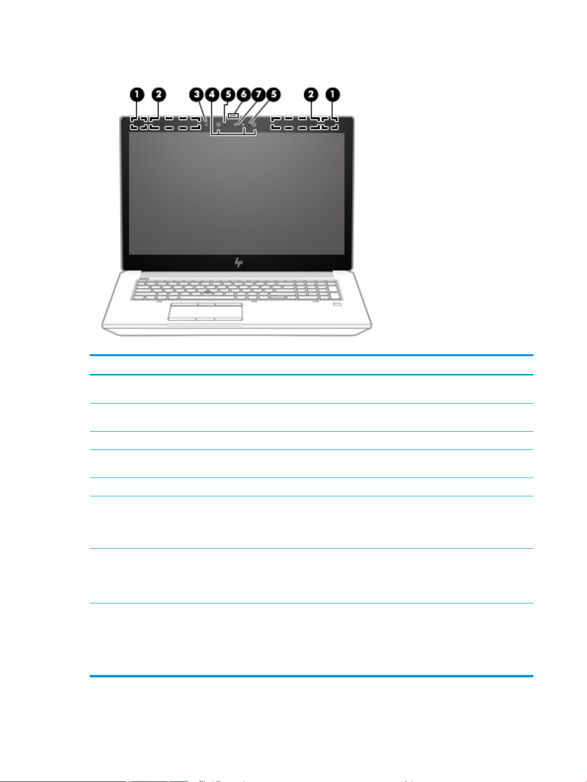
Display
Table 2-3 Display components and their descriptions
Component Description
(1) WLAN antennas (select
products only)*
(2) WWAN antennas (select
products only)*
(3) Ambient light sensor Adjusts the brightness of the display, depending on the ambient light.
(4) Camera light(s) (select
products only)
(5) Internal microphones (2) Record sound.
(6) Camera privacy cover (select
products only)
(7) Camera(s) (select products
only)
*The antennas are not visible from the outside of the computer. For optimal transmission, keep the areas immediately around the
antennas free from obstructions.
For wireless regulatory notices, see the section of the Regulatory, Safety, and Environmental Notices that applies to your country or
region. To access this guide:
▲ Type HP Documentation in the taskbar search box, and then select HP Documentation.
Send and receive wireless signals to communicate with wireless local area networks
(WLANs).
Send and receive wireless signals to communicate with wireless wide area networks
(WWANs).
On: One or more cameras are in use.
When closed, the camera privacy cover conceals the camera.
● To reveal the camera, slide the cover to the left.
● To conceal the camera, slide the cover to the right.
Allow(s) you to video chat, record video, and record still images. Some cameras also allow
a facial recognition logon to Windows, instead of a password logon.
NOTE: Camera functions vary depending on the camera hardware and software installed
on your product.
10 Chapter 2 Components
Page 25
Keyboard area
Touchpad settings
To adjust touchpad settings and gestures, or to turn o the touchpad:
1. Type touchpad settings in the taskbar search box, and then press enter.
2. Choose a setting.
To turn on the touchpad:
1. Type touchpad settings in the taskbar search box, and then press enter.
2. Using an external mouse, click the Touchpad button.
– or –
▲ Press the Tab key repeatedly until the pointer rests on the Touchpad button. Then press the spacebar to
select the button.
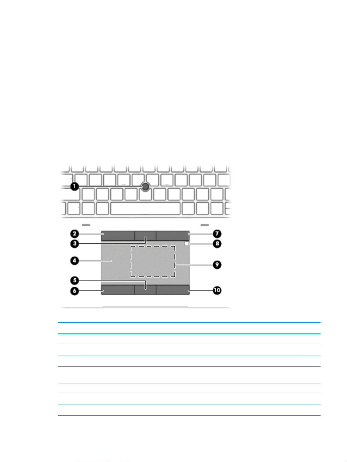
Table 2-4 Touchpad components and their descriptions
Component Description
(1) Pointing stick Moves the pointer on the screen.
(2) Left pointing stick button Functions like the left button on an external mouse.
(3) Center pointing stick button Functions like the center button on an external mouse.
(4) Touchpad zone Reads your nger gestures to move the pointer or activate items
on the screen.
(5) Center touchpad button Functions like the center button on an external mouse.
(6) Left touchpad button Functions like the left button on an external mouse.
(7) Right pointing stick button Functions like the right button on an external mouse.
Keyboard area 11
Page 26

Table 2-4 Touchpad components and their descriptions (continued)
Component Description
(8) HP DreamColor sensor (select products only) A colorimeter that brings integrated color calibration to your
(9) Near Field Communications (NFC) tapping area
and antenna (select products only)*
(10) Right touchpad button Functions like the right button on an external mouse.
*The antennas are not visible from the outside of the computer. For optimal transmission, keep the areas immediately around the
antennas free from obstructions.
For wireless regulatory notices, see the section of the Regulatory, Safety, and Environmental Notices that applies to your country or
region.
To access this guide:
▲ Type HP Documentation in the taskbar search box, and then select HP Documentation.
display. This built-in measurement instrument provides the
ability to recalibrate a DreamColor color preset without the use
of an external measurement instrument. To select a color preset
or launch the calibration tool, select the HP DreamColor icon in
the Windows taskbar. Make a selection from the menu and
follow the on-screen instructions.
NOTE: For accurate calibration, keep the sensor window clean
and free from obstructions.
Allows you to wirelessly share information when you tap it with
an NFC-enabled device.
12 Chapter 2 Components
Page 27
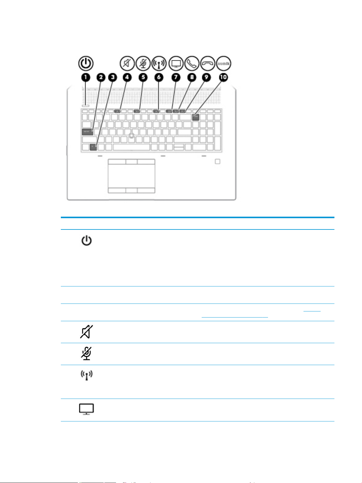
Lights
Table 2-5 Lights and their descriptions
Component Description
(1) Power light ● On: The computer is on.
● Blinking (select products only): The computer is in the Sleep
state, a power-saving state. The computer shuts o power
to the display and other unneeded components.
● O: Depending on your computer model, the computer is
o, in Hibernation, or in Sleep. Hibernation is the powersaving state that uses the least amount of power.
(2) Caps lock light On: Caps lock is on, which switches the key input to all capital
letters.
(3) Fn lock light On: The fn key is locked. For more information, see Hot keys
(select products only) on page 16.
(4) Mute light ● On: Computer sound is o.
● O: Computer sound is on.
(5) Microphone mute light ● On: Microphone is o.
● O: Microphone is on.
(6) Wireless light On: An integrated wireless device, such as a wireless local area
network (WLAN) device and/or a Bluetooth® device, is on.
NOTE: On some models, the wireless light is amber when all
wireless devices are o.
(7) Sharing or presenting light On: Sharing is on.
Keyboard area 13
Page 28
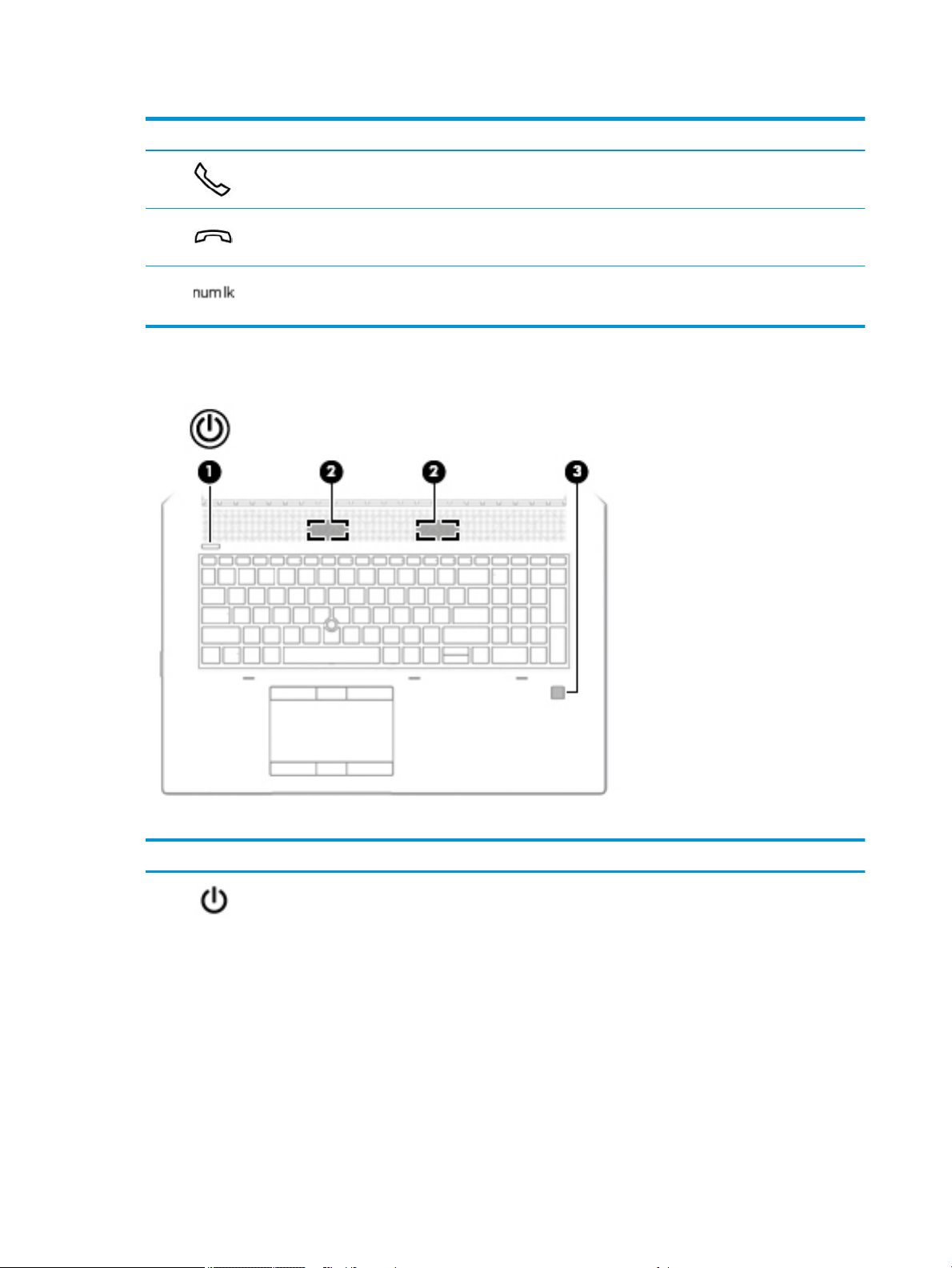
Table 2-5 Lights and their descriptions (continued)
Component Description
(8) Call answer light On: Call answer is on.
(9) Call end light On: Call end is on.
(10) Num lk light On: Num lock is on.
Buttons, speakers, and ngerprint reader
Table 2-6 Buttons, speakers, and ngerprint reader and their descriptions
Component Description
(1) Power button ● When the computer is o, press the button to turn on the
14 Chapter 2 Components
computer.
● When the computer is on, press the button briey to initiate
Sleep.
● When the computer is in the Sleep state, press the button
briey to exit Sleep (select products only).
● When the computer is in Hibernation, press the button
briey to exit Hibernation.
CAUTION: Pressing and holding down the power button results
in the loss of unsaved information.
If the computer has stopped responding and shutdown
procedures are ineective, press and hold the power button for at
least 5 seconds to turn o the computer.
Page 29
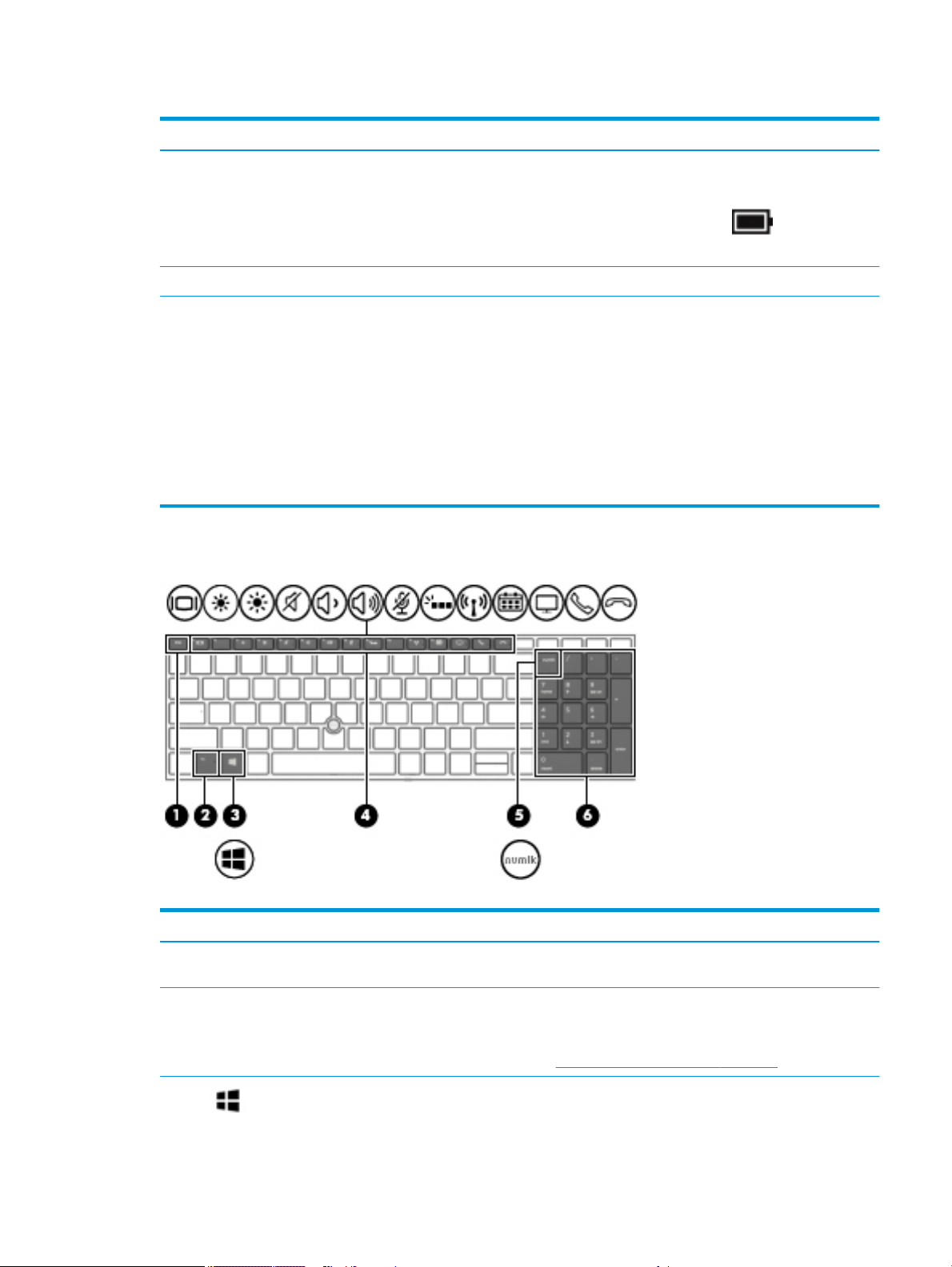
Table 2-6 Buttons, speakers, and ngerprint reader and their descriptions (continued)
Component Description
(2) Speakers Produce sound.
(3) Fingerprint reader (select products only) Allows a ngerprint logon to Windows, instead of a password
Special keys
To learn more about your power settings, see your power
options.
▲ Right-click the Power meter icon and then select
Power Options.
logon.
▲ Touch your nger to the ngerprint reader.
IMPORTANT: To prevent ngerprint logon issues, make
sure when you register your ngerprint that all sides of your
nger are registered by the ngerprint reader.
IMPORTANT: To verify that your computer has a ngerprint
reader, type Sign-in options in the taskbar search box and
follow the on-screen instructions. If Fingerprint reader is listed
as an option, then your computer includes a ngerprint reader.
Table
2-7 Special keys and their descriptions
Component Description
(1) esc key Displays system information when pressed in combination with
the fn key.
(2) fn key Executes frequently used system functions when pressed in
combination with another key. Such key combinations are called
hot keys.
See Hot keys (select products only) on page 16.
(3) Windows key Opens the Start menu.
Keyboard area 15
Page 30

Table 2-7 Special keys and their descriptions (continued)
Component Description
(4) Action keys Execute frequently used system functions.
(5) num lk key Alternates between the navigational and numeric functions on
(6) Integrated numeric keypad A separate keypad to the right of the alphabet keyboard. When
Hot keys (select products only)
A hot key is the combination of the fn key and another key.
To use a hot key:
▲ Press the fn key, and then press one of the keys listed in the following table.
NOTE: Pressing the Windows key again will close the Start
menu.
the integrated numeric keypad.
num lk is pressed, the integrated keypad can be used like an
external numeric keypad.
NOTE: If the keypad function is active when the computer is
turned o, that function is reinstated when the computer is
turned back on.
Table
2-8 Hot keys and their descriptions
Key Description
C Turns on scroll lock.
E Turns on the insert function.
R Breaks the operation.
S Sends a programing query.
W Pauses the operation.
16 Chapter 2 Components
Page 31

Bottom
Table 2-9 Bottom components and their descriptions
Component Description
(1) Vent Enables airow to cool internal components.
NOTE: The computer fan starts up automatically to cool
internal components and prevent overheating. It is normal
for the internal fan to cycle on and o during routine
operation.
(2) Service door release latch with lock screw Releases the service door.
Bottom 17
Page 32

Cover
Table 2-10 Cover components and their descriptions
Component Description
Rear
Internal microphones (2) Record sound.
Table
2-11 Rear components and their descriptions
Component Description
Vents (2) Enable airow to cool internal components.
NOTE: The computer fan starts up automatically to cool internal
components and prevent overheating. It is normal for the internal
fan to cycle on and o during routine operation.
18 Chapter 2 Components
Page 33

Labels
The labels axed to the computer provide information you may need when you troubleshoot system
problems or travel internationally with the computer. Labels may be in paper form or imprinted on the
product.
IMPORTANT: Check the following locations for the labels described in this section: the bottom of the
computer, inside the battery bay, under the service door, on the back of the display, or on the bottom of a
tablet kickstand.
● Service label—Provides important information to identify your computer. When contacting support, you
may be asked for the serial number, the product number, or the model number. Locate this information
before you contact support.
Table 2-12 Service label components
Component
(1) HP product name
(2) Product ID
(3) Serial number
(4) Warranty period
● Regulatory label(s)—Provide(s) regulatory information about the computer.
● Wireless certication label(s)—Provide(s) information about optional wireless devices and the approval
markings for the countries or regions in which the devices have been approved for use.
Labels 19
Page 34

Inserting a SIM card (select products only)
IMPORTANT: Inserting a SIM card of the wrong size could damage the SIM card or cause the SIM card to
become stuck in the slot. The use of SIM card adapters is not recommended. To prevent damage to the SIM
card or the connectors, use minimal force when inserting or removing a SIM card.
NOTE: Before purchasing a SIM card, follow these instructions to determine the correct SIM card size for
your computer:
1. Go to http://www.hp.com/support, and then search for your computer by product name or number.
2. Select Product Information.
3. Refer to the listed options to determine which card to purchase.
To insert a SIM card, follow these steps:
1. Turn o the computer by using the Shut down command.
2. Close the display.
3. Disconnect all external devices connected to the computer.
4. Unplug the power cord from the AC outlet.
5. Turn the computer upside down on a at surface, with the battery bay toward you.
6. Remove the battery.
7. Insert the SIM card into the SIM card slot, and then press in on the SIM card until it is rmly seated.
NOTE: The SIM card in your computer may look slightly dierent from the illustration in this section.
NOTE: See the image on the battery bay to determine which way the SIM card should be inserted into
your computer.
To remove a SIM card, press in on the SIM card, and then remove it from the slot.
20 Chapter 2 Components
Page 35

3 Illustrated parts catalog
Computer major components
NOTE: HP continually improves and changes product parts. For complete and current information on
supported parts for your computer, go to http://partsurfer.hp.com, select your country or region, and then
follow the on-screen instructions.
NOTE: Details about your computer, including model, serial number, product key, and length of warranty,
are on the service tag at the bottom of your computer. See Labels on page 19 for details.
Computer major components 21
Page 36

Table 3-1 Computer major components descriptions and part numbers
Item Component Spare part number
(1) Display assembly
For more display assembly spare part information, see Display assembly subcomponents
on page 25.
For use in models with a DreamColor display and FHD/IR webcam L67970-001
For use in models with a DreamColor display and HD webcam L70625-001
(2) Keyboard
For a list of keyboard country codes, see Keyboard on page 46.
(3) Power button board (includes cable) L28466-001
(4) Solid-state drive storage board L30397-001
Hard drive storage board L30396-001
(5) Top cover L30661-001
(6) Smart card board L77070-001
(7) Touchpad L30663-001
(8) NFC module L02249-001
NFC antenna (not illustrated) L30662-001
(9) Fingerprint reader L67969-001
(10) Optical drive L72616-001
L28407-xxx
(11) Hard drive
2 TB, 5400 rpm, 7 mm, 2.5 inch 912487-850
1 TB, 5400 rpm, 2.5 inch 778192-001
500 GB, 7200 rpm, 7 mm 703267-001
(12) Hard drive bracket (included in hard drive hardware kit) L30394-001
(13) Hard drive connector (included in hard drive hardware kit) L30394-001
(14) Battery L07044-850
(15a) Solid-state drive (customer self repair, for use under the service door)
2 TB, NVMe, PCIe, TLC L67984-001
1 TB, NVMe, PCIe, TLC L67983-001
512 GB, NVMe, PCIe, TLC L67982-001
512 GB, NVMe, PCIe, TLC, self-encrypting drive (SED), Opal 2 L67985-001
256 GB, NVMe, PCIe, TLC L67981-001
1 TB, SATA, TLC L67988-001
512 GB, SATA, TLC, FIPS-140-2 L67980-001
256 GB, SATA, TLC L67987-001
16 GB, Optane memory module L67979-001
22 Chapter 3 Illustrated parts catalog
Page 37

Table 3-1 Computer major components descriptions and part numbers (continued)
Item Component Spare part number
(15b) Solid-state drive (non-customer replaceable, for use on the bottom of the system board;
includes thermal pad)
2 TB, NVMe, PCIe, TLC L76724-001
1 TB, NVMe, PCIe, TLC L76723-001
512 GB, NVMe, PCIe, TLC L76722-001
512 GB, NVMe, PCIe, TLC, self-encrypting drive (SED), Opal 2 L76725-001
256 GB, NVMe, PCIe, TLC L76721-001
1 TB, SATA, TLC L76727-001
512 GB, SATA, TLC, FIPS-140-2 L76720-001
256 GB, SATA, TLC L76726-001
16 GB, Optane memory module L76719-001
(16) Speaker L28477-001
(17) WWAN module
Intel XMM™ 7360 LTE-Advanced (CAT 9) L15398-001
(18) Middle cover L28471-001
(19) Discrete MXM graphics daughter card
AMD Radeon, 4 GB L70628-001
NVIDIA Quadro T1000, 4 GB L70629-001
NVIDIA Quadro RTX 3000, 6 GB L70630-001
NVIDIA Quadro RTX 4000, 8 GB L70631-001
NVIDIA Quadro RTX 5000, 16 GB L70632-001
(20) Memory module (DDR4-2666)
For use in the memory sockets directly under the service door (customer-accessible):
● 32 GB L50384-001
● 16 GB, ECC L24981-001
● 16 GB 937438-850
● 8 GB 937236-850
● 4 GB L10598-850
For use in the memory sockets under the system board (non-customer accessible)
(includes thermal pad):
● 32 GB L50384-006
● 16 GB, ECC L24981-006
● 16 GB L76709-006
● 8 GB L76708-006
Computer major components 23
Page 38

Table 3-1 Computer major components descriptions and part numbers (continued)
Item Component Spare part number
● 4 GB L76710-006
(21) System board (includes integrated processor and replacement thermal material, see System board on page 63)
All system boards use the following part numbers:
xxxxxx-001: Non-Windows operating systems
xxxxxx-601: Windows operating system
Intel Core i9-9880H processor L67965-xx1
Intel Core i7-9850H processor (models without WLAN and Bluetooth) L71661-xx1
Intel Core i7-9850H processor L67964-xx1
Intel Core i7-9750H processor (models without WLAN and Bluetooth) L71660-xx1
Intel Core i7-9750H processor L67963-xx1
Intel Core i5-9400H processor L67962-xx1
Intel Core i5-9300H processor L67961-xx1
Intel Xeon E-2286M processor L67966-xx1
(22) RTC battery L72624-001
(23) Right (GPU) fan L30389-001
(24) Left (CPU) fan L30388-001
(25) Heat sink (for use in models with NVIDIA Quadro P1000 (N19P) discrete graphics memory) L67976-001
Heat sink (for use in models with NVIDIA Quadro RTX 3000, 4000, or 5000 (N19E) discrete
graphics memory)
(26) Heat sink (for use in models with UMA graphics) L67975-001
(27) Service door L30395-001
L67977-001
24 Chapter 3 Illustrated parts catalog
Page 39

Display assembly subcomponents
Table 3-2 Display subcomponent descriptions and part numbers
Item Component Spare part number
(1) Display bezel
For use in models with a IR webcam and transparent webcam privacy cover L67991-001
For use in models with an RGB webcam and transparent webcam privacy cover L67993-001
For use in models without a webcam and a transparent webcam privacy cover L71658-001
(2) Webcam cover L70637-001
(3) Raw display panel (includes cables, display panel adhesive, and bezel adhesive)
Non-touch panel L72617-001
Touch panel L67997-001
(4) Hinges (include display panel adhesive and bezel adhesive)
For use in models with a non-touch screen L28464-001
Display assembly subcomponents 25
Page 40

Table 3-2 Display subcomponent descriptions and part numbers (continued)
Item Component Spare part number
For use in models with a touch screen L77464-001
(5) Camera module
HD camera L67972-001
FHD + IR camera L67971-001
Microphone module (not shown, includes display panel adhesive and bezel adhesive) L34855-001
(6) WWAN antenna (included in four antenna kit, includes display panel adhesive and bezel
adhesive)
For use in models with a non-touch screen L30400-001
For use in models with a touch screen L67990-001
(7) WLAN antenna (included in four antenna kit, includes display panel adhesive and bezel
adhesive)
For use in models with a non-touch screen L30400-001
For use in models with a touch screen L67990-001
(8) Display cable (includes display panel adhesive and bezel adhesive)
For use in non-touch models L67995-001
For use in models with a touch screen L77463-001
(9) DreamColor board (includes cable, display panel adhesive, and bezel adhesive) L31321-001
(10) Ambient light sensor board (includes cable, display panel adhesive, and bezel adhesive) L30665-001
(11) Display enclosure (includes display panel adhesive and bezel adhesive)
For use in models with a non-touch screen L28463-001
For use in models with a touch screen L67967-001
26 Chapter 3 Illustrated parts catalog
Page 41

Miscellaneous parts
Table 3-3 Miscellaneous part descriptions and part numbers
Component Spare part number
AC adapter (200 W PFC, smart, slim, 4.5 mm) L00818-850
Protective tape kit (includes protective tape for the WLAN module, WWAN module, and power button) L34854-001
Optical drive bezel (includes optical drive cable) L30398-001
Plastics kit (includes optical drive cradle and plastic placeholders for the fan, optical drive, ngerprint
reader, SD card)
Rubber kit (includes GPU rubber) L28476-001
Bracket kit, (includes memory shield, optical drive bracket, ngerprint reader bracket, and display
connector bracket)
Screw kit L28478-001
Power cord
For use in Argentina L32029-001
For use in Australia 100661-021
For use in Brazil L32030-001
For use in Denmark 130627-014
For use in Europe 100614-016
For use in India 403440-008
For use in Israel 398062-011
For use in Italy L32031-001
For use in Japan 653326-005
For use in North America 121565-023
L71657-001
For use in the People’s Republic of China 286496-024
For use in South Africa 187487-012
For use in South Korea 231216-015
For use in Switzerland 150304-015
For use in Taiwan 393312-008
For use in Thailand 285052-013
For use in the United Kingdom 100613-021
Miscellaneous parts 27
Page 42

4 Removal and replacement procedures
preliminary requirements
Tools required
You will need the following tools to complete the removal and replacement procedures:
● Non-conductive, non-marking pry tool
● Magnetic Torx T5 screwdriver
● Magnetic Phillips P0 screwdriver
● Magnetic Phillips P1 screwdriver
Service considerations
The following sections include some of the considerations that you must keep in mind during disassembly
and assembly procedures.
NOTE: As you remove each subassembly from the computer, place the subassembly (and all accompanying
screws) away from the work area to prevent damage.
Plastic parts
IMPORTANT: Using excessive force during disassembly and reassembly can damage plastic parts.
Cables and connectors
IMPORTANT: When servicing the computer, be sure that cables are placed in their proper locations during
the reassembly process. Improper cable placement can damage the computer.
Cables must be handled with extreme care to avoid damage. Apply only the tension required to unseat or seat
the cables during removal and insertion. Handle cables by the connector whenever possible. In all cases, avoid
bending, twisting, or tearing cables. Be sure that cables are routed in such a way that they cannot be caught
or snagged by parts being removed or replaced. Handle ex cables with extreme care; these cables tear
easily.
28 Chapter 4 Removal and replacement procedures preliminary requirements
Page 43

Drive handling
IMPORTANT: Drives are fragile components that must be handled with care. To prevent damage to the
computer, damage to a drive, or loss of information, observe these precautions:
Before removing or inserting a hard drive, shut down the computer. If you are unsure whether the computer is
o or in Hibernation, turn the computer on, and then shut it down through the operating system.
Before handling a drive, be sure that you are discharged of static electricity. While handling a drive, avoid
touching the connector.
Before removing an optical drive, be sure that a disc is not in the drive and be sure that the optical drive tray is
closed.
Handle drives on surfaces covered with at least 2.54 cm (1 inch) of shock-proof foam.
Avoid dropping drives from any height onto any surface.
After removing a hard drive or an optical drive, place it in a static-proof bag.
Avoid exposing an internal hard drive to products that have magnetic elds, such as monitors or speakers.
Avoid exposing a drive to temperature extremes or liquids.
If a drive must be mailed, place the drive in a bubble pack mailer or other suitable form of protective
packaging and label the package “FRAGILE.”
Workstation guidelines
Follow these grounding workstation guidelines:
● Cover the workstation with approved static-shielding material.
● Use a wrist strap connected to a properly grounded work surface and use properly grounded tools and
equipment.
● Use conductive eld service tools, such as cutters, screw drivers, and vacuums.
● When xtures must directly contact dissipative surfaces, use xtures made only of static-safe materials.
● Keep the work area free of nonconductive materials, such as ordinary plastic assembly aids
and polystyrene foam.
● Handle ESD-sensitive components, parts, and assemblies by the case or PCM laminate. Handle these
items only at static-free workstations.
● Avoid contact with pins, leads, or circuitry.
● Turn o power and input signals before inserting or removing connectors or test equipment.
Electrostatic discharge information
A sudden discharge of static electricity from your nger or other conductor can destroy static-sensitive
devices or microcircuitry. Often the spark is neither felt nor heard, but damage occurs. An electronic device
exposed to electrostatic discharge (ESD) might not appear to be aected at all and can work perfectly
throughout a normal cycle. The device might function normally for a while, but it has been degraded in the
internal layers, reducing its life expectancy.
Networks built into many integrated circuits provide some protection, but in many cases, the discharge
contains enough power to alter device parameters or melt silicon junctions.
Electrostatic discharge information 29
Page 44

IMPORTANT: To prevent damage to the device when you are removing or installing internal components,
observe these precautions:
Keep components in their electrostatic-safe containers until you are ready to install them.
Before touching an electronic component, discharge static electricity by using the guidelines described in this
section.
Avoid touching pins, leads, and circuitry. Handle electronic components as little as possible.
If you remove a component, place it in an electrostatic-safe container.
Generating static electricity
Note the following:
● Dierent activities generate dierent amounts of static electricity.
● Static electricity increases as humidity decreases.
Table 4-1 Static electricity occurrence based on activity and humidity
Relative humidity
Event 55% 40% 10%
Walking across carpet
Walking across vinyl oor
Motions of bench worker
Removing DIPs (dual in-line packages) from plastic tube
Removing DIPs from vinyl tray
Removing DIPs from polystyrene foam
Removing bubble pack from PCB (printed circuit board)
Packing PCBs in foam-lined box
Multiple electric components can be packaged together in plastic tubes, trays, or polystyrene foam.
NOTE: As little as 700 V can degrade a product.
Preventing electrostatic damage to equipment
Many electronic components are sensitive to ESD. Circuitry design and structure determine the degree of
sensitivity. The following packaging and grounding precautions are necessary to prevent static electricity
damage to electronic components.
● To avoid hand contact, transport products in static-safe containers such as tubes, bags, or boxes.
7,500 V
3,000 V
400 V
400 V
2,000 V
3,500 V
7,000 V
5,000 V
15,000 V
5,000 V
800 V
700 V
4,000 V
5,000 V
20,000 V
11,000 V
35,000 V
12,000 V
6,000 V
2,000 V
11,500 V
14,500 V
26,500 V
21,000 V
● Protect all electrostatic parts and assemblies with conductive or approved containers or packaging.
● Keep electrostatic-sensitive parts in their containers until they arrive at static-free stations.
● Place items on a grounded surface before removing them from their container.
● Always be properly grounded when touching a sensitive component or assembly.
30 Chapter 4 Removal and replacement procedures preliminary requirements
Page 45

● Avoid contact with pins, leads, or circuitry.
● Place reusable electrostatic-sensitive parts from assemblies in protective packaging or conductive
foam.
Personal grounding methods and equipment
Use the following equipment to prevent static electricity damage to electronic components:
● Wrist straps are exible straps with a maximum of 1 MΩ ±10% resistance in the ground cords. To
provide proper ground, a strap must be worn snug against bare skin. The ground cord must be
connected and t snugly into the banana plug connector on the grounding mat or workstation.
● Heel straps/Toe straps/Boot straps can be used at standing workstations and are compatible with
most types of shoes or boots. On conductive oors or dissipative oor mats, use them on both feet with
a maximum of 1 MΩ ±10% resistance between the operator and ground.
Table 4-2 Static shielding protection levels
Static shielding protection levels
Method Voltage
Antistatic plastic
Carbon-loaded plastic
Metallized laminate
Grounding the work area
To prevent static damage at the work area, use the following precautions:
● Cover the work surface with approved static-dissipative material. Provide a wrist strap connected to the
work surface and properly grounded tools and equipment.
● Use static-dissipative mats, foot straps, or air ionizers to give added protection.
● Handle electrostatic sensitive components, parts, and assemblies by the case or PCB laminate. Handle
them only at static-free work areas.
● Turn o power and input signals before inserting and removing connectors or test equipment.
● Use xtures made of static-safe materials when xtures must directly contact dissipative surfaces.
● Keep work area free of nonconductive materials such as ordinary plastic assembly aids and polystyrene
foam.
● Use eld service tools, such as cutters, screwdrivers, and vacuums, that are conductive.
Recommended materials and equipment
1,500
7,500
15,000
HP recommends the following materials and equipment to prevent static electricity:
● Antistatic tape
● Antistatic smocks, aprons, or sleeve protectors
● Conductive bins and other assembly or soldering aids
● Conductive foam
● Conductive tabletop workstations with ground cord of 1 MΩ ±10% resistance
Electrostatic discharge information 31
Page 46

● Static-dissipative table or oor mats with hard tie to ground
● Field service kits
● Static awareness labels
● Wrist straps and footwear straps providing 1 MΩ ±10% resistance
● Material handling packages
● Conductive plastic bags
● Conductive plastic tubes
● Conductive tote boxes
● Opaque shielding bags
● Transparent metallized shielding bags
● Transparent shielding tubes
Packaging and transporting guidelines
Follow these grounding guidelines when packaging and transporting equipment:
● To avoid hand contact, transport products in static-safe tubes, bags, or boxes.
● Protect ESD-sensitive parts and assemblies with conductive or approved containers or packaging.
● Keep ESD-sensitive parts in their containers until the parts arrive at static-free workstations.
● Place items on a grounded surface before removing items from their containers.
● Always be properly grounded when touching a component or assembly.
● Store reusable ESD-sensitive parts from assemblies in protective packaging or nonconductive foam.
● Use transporters and conveyors made of antistatic belts and roller bushings. Be sure that mechanized
equipment used for moving materials is wired to ground and that proper materials are selected to avoid
static charging. When grounding is not possible, use an ionizer to dissipate electric charges.
32 Chapter 4 Removal and replacement procedures preliminary requirements
Page 47

5 Removal and replacement procedures for
Customer Self-Repair parts
This chapter provides removal and replacement procedures for Customer Self-Repair parts.
NOTE: The Customer Self-Repair program is not available in all locations. Installing a part not supported by
the Customer Self-Repair program may void your warranty. Check your warranty to determine if Customer
Self-Repair is supported in your location.
Component replacement procedures
NOTE: Details about your computer, including model, serial number, product key, and length of warranty,
are on the service tag at the bottom of your computer. See Labels on page 19 for details.
NOTE: HP continually improves and changes product parts. For complete and current information on
supported parts for your computer, go to http://partsurfer.hp.com, select your country or region, and then
follow the on-screen instructions.
There are as many as 14 screws that must be removed, replaced, and/or loosened when servicing Customer
Self-Repair parts. Make special note of each screw size and location during removal and replacement.
Preparation for disassembly
See Removal and replacement procedures preliminary requirements on page 28 for initial safety procedures.
1. Turn o the computer. If you are unsure whether the computer is o or in Hibernation, turn the
computer on, and then shut it down through the operating system.
2. Disconnect the power from the computer by unplugging the power cord from the computer.
3. Disconnect all external devices from the computer.
4. Remove the any smart cards and memory cards.
Component replacement procedures 33
Page 48

Service door
Description Spare part number
Service door L30395-001
Before removing the service door, follow these steps:
▲ Prepare the computer for disassembly (Preparation for disassembly on page 33).
Remove the service door:
1. Turn the computer upside down on a at surface.
2. Remove the optional lock screw (1), slide the service door release latch (2) and then slide the service
door to remove it (3).
Reverse the removal procedures to install the service door.
34 Chapter 5 Removal and replacement procedures for Customer Self-Repair parts
Page 49

Battery
Description Spare part number
Battery L07044-850
Before removing the battery, follow these steps:
1. Prepare the computer for disassembly (Preparation for disassembly on page 33).
2. Remove the service door (see Service door on page 34).
Remove the battery:
To remove the user-replaceable battery, refer to the following steps and illustration that most closely match
your computer:
▲ Slide the battery release latches (1) and then pull the battery tab (2) up to remove the battery from the
computer.
NOTE: The battery release latches automatically return to their original positions.
Reverse this procedure to install the battery module.
Component replacement procedures 35
Page 50

Hard drive (HDD)
Description Spare part number
2 TB, 5400 rpm, 7 mm, 2.5 inch 912487-850
1 TB, 5400 rpm, 2.5 inch 778192-001
500 GB, 7200 rpm, 7 mm 703267-001
Hard drive bracket and connector (included in hard drive hardware kit) L30394-001
Before removing the hard drive, follow these steps:
1. Prepare the computer for disassembly (Preparation for disassembly on page 33).
2. Remove the service door (see Service door on page 34).
3. Remove the battery (see Battery on page 35).
Remove the hard drive:
1. Release the three captive Phillips screws (1) that secure the drive to the system board.
2. Lift the hard drive release tab (2)
3. Lift the drive (3) to remove it.
36 Chapter 5 Removal and replacement procedures for Customer Self-Repair parts
Page 51

4. If it is necessary to replace the hard drive bracket, remove the four Phillips M3.0 × 3.0 screws (1) that
secure the bracket to the hard drive, and then lift the bracket straight up (2) and remove the it from the
hard drive.
Reverse this procedure to install the hard drive.
Component replacement procedures 37
Page 52

Solid-state drives (SSD)
Description Spare part number
2 TB, NVMe, PCIe, TLC L67984-001
1 TB, NVMe, PCIe, TLC L67983-001
512 GB, NVMe, PCIe, TLC L67982-001
512 GB, NVMe, PCIe, TLC, self-encrypting drive (SED), Opal 2 L67985-001
256 GB, NVMe, PCIe, TLC L67981-001
1 TB, SATA, TLC L67988-001
512 GB, SATA, TLC, FIPS-140-2 L67980-001
256 GB, SATA, TLC L67987-001
16 GB, Optane memory module L67979-001
NOTE: An additional solid-state drive slot is available under the system board that is not a customer self-
repair part.
Before removing the solid-state drives, follow these steps:
1. Remove the service door (see Service door on page 34).
2. Remove the battery (see Battery on page 35).
Remove the solid-state drives:
1. Remove the Phillips M2.0 × 3.0 screw (1) that secures the drive to the system board.
2. Remove the drive by pulling it away from the connector (2).
NOTE: Solid-state drives are designed with notches to prevent incorrect insertion.
Reverse this procedure to install the solid-state drives.
38 Chapter 5 Removal and replacement procedures for Customer Self-Repair parts
Page 53

Optical drive
Description Spare part number
Optical drive L72616-001
Optical drive bracket (included in bracket kit) L70624-001
Before removing the optical drive, follow these steps:
1. Prepare the computer for disassembly (Preparation for disassembly on page 33).
2. Remove the service door (see Service door on page 34).
3. Remove the battery (see Battery on page 35).
Remove the optical drive:
1. Remove the Phillips M2.0 × 2.0 screw (1) that secures the optical drive to the computer.
2. Use a thin tool (2) to release the optical drive from the computer.
3. Pull the optical drive (3) away from the computer to remove it.
Component replacement procedures 39
Page 54

4. To remove the optical drive bracket, remove the two screws (1) securing the bracket to the optical drive,
and then remove the bracket (2).
Reverse this procedure to install the optical drive.
40 Chapter 5 Removal and replacement procedures for Customer Self-Repair parts
Page 55

Memory modules
NOTE: Customer-accessible primary and expansion memory is installed in a side-by-side conguration
directly under the service door.
If only one memory module is installed, it must be installed in the socket labeled 1.
IMPORTANT: Two additional memory slots are available under the system board, requiring removal of the
system board to access. Those additional slots are not customer self-repair. For more information, see
Memory modules on page 75.
Description Spare part number
32 GB L50384-001
16 GB, ECC L24981-001
16 GB 937438-850
8 GB 937236-850
4 GB L10598-850
Before adding new memory, make sure you update the computer to the latest BIOS.
IMPORTANT: Failure to update the computer to the latest BIOS before installing new memory might result in
various system problems.
Before removing the memory module, follow these steps:
1. Prepare the computer for disassembly (Preparation for disassembly on page 33).
2. Remove the service door (see Service door on page 34).
3. Remove the battery (see Battery on page 35).
Remove the memory module:
1. Spread the retaining tabs (1) on each side of the memory module slot to release the memory module.
(The edge of the module opposite the slot rises away from the computer.)
Component replacement procedures 41
Page 56

2. Remove the memory module (2) by pulling the module away from the slot at an angle.
NOTE: Memory modules are designed with a notch to prevent incorrect insertion into the memory
module slot.
NOTE: The computer uses two memory sockets. The socket labeled 2 houses the expansion memory
module and the socket labeled 1 houses the primary memory module. The removal procedure is the
same for both memory sockets.
Reverse this procedure to install a memory module.
42 Chapter 5 Removal and replacement procedures for Customer Self-Repair parts
Page 57

SIM card
Before removing the SIM card, follow these steps:
1. Prepare the computer for disassembly (Preparation for disassembly on page 33).
2. Remove the bottom cover (see Service door on page 34).
3. Remove the battery (see Battery on page 35).
Remove the SIM card:
1. Lift the SIM card bracket (1).
2. Lift the SIM card (2) to remove it.
Reverse this procedure to install a SIM card.
Component replacement procedures 43
Page 58

WWAN module
The WWAN module is available on select models only.
Description Spare part number
Intel XMM 7360 LTE-Advanced (CAT 9) L15398-001
Before removing the WWAN module, follow these steps:
1. Prepare the computer for disassembly (Preparation for disassembly on page 33).
2. Remove the service door (see Service door on page 34).
3. Remove the battery (see Battery on page 35).
NOTE: The red WWAN antenna cable is connected to the WWAN module Main terminal. The blue WWAN
antenna cable is connected to the WWAN module Aux terminal.
Remove the WWAN module:
1. Position the computer upside-down.
2. Remove the plastic cover (1) that protects the antenna connectors.
3. Disconnect the WWAN antenna cables (2) from the terminals on the WWAN module.
4. Remove the Phillips M2.0 × 2.0 screw (3) that secures the WWAN module to the computer. (The edge of
the module opposite the slot rises away from the computer.)
44 Chapter 5 Removal and replacement procedures for Customer Self-Repair parts
Page 59

5. Remove the WWAN module (4) by pulling the module away from the slot at an angle.
NOTE: WWAN modules are designed with a notch to prevent incorrect insertion.
NOTE: If the WWAN antennas are not connected to the terminals on the WWAN module, the protective
sleeves must be installed on the antenna connectors, as shown in the following illustration.
Reverse this procedure to install the WWAN module.
Component replacement procedures 45
Page 60

Keyboard
Description Spare part number Description Spare part number
For use in Africa (French) L28407-FP1 For use in Japan L28407-291
For use in Belgium L28407-A41 For use in Latin America L28407-161
For use in Brazil L28407-201 For use in the Netherlands L28407-B31
For use in Bulgaria L28407-261 For use in Portugal L28407-131
For use in Canada (English) L28407-DB1 For use in Russia L28407-251
For use in the Czech Republic and
Slovenia
For use in Denmark L28407-081 For use in Slovenia L28407-BA1
For use in Denmark, Finland, and
Norway
For use in France L28407-051 For use in Spain L28407-071
For use in Germany L28407-041 For use in Sweden and Finland L28407-B71
For use in Greece L28407-151 For use in Switzerland L28407-BG1
For use in Hungary L28407-211 For use in Thailand L28407-281
For use in Iceland L28407-DD1 For use in Turkey L28407-141
For use in India L28407-D61 For use in Taiwan L28407-AB1
For use in Israel L28407-BB2 For use in the United Kingdom L28407-031
For use in Italy L28407-061 For use in the United States L28407-001
L28407-FL1 For use in Saudi Arabia L28407-171
L28407-DH1 For use in South Korea L28407-AD1
Before removing the keyboard, follow these steps:
1. Prepare the computer for disassembly (Preparation for disassembly on page 33).
2. Remove the service door (see Service door on page 34).
3. Remove the battery (see Battery on page 35).
Remove the keyboard:
1. Remove the three Phillips M2.5 × 8.0 screws that secure the keyboard.
46 Chapter 5 Removal and replacement procedures for Customer Self-Repair parts
Page 61

2. Use a thin plastic tool to release the keyboard from the bottom.
3. Turn over the computer, and then insert a case utility tool (1) or similar thin, plastic tool between the
front edge of the keyboard and the bottom cover.
Component replacement procedures 47
Page 62

4. Lift the back edge (2) of the keyboard until it separates from the front edge of the bottom cover.
5. Rotate the keyboard face down (1).
6. Release the zero insertion force (ZIF) connector (2), and then disconnect the following cables (3) from
the system board:
● Touchpad button cable
● Keyboard backlight cable
● Keyboard cable
48 Chapter 5 Removal and replacement procedures for Customer Self-Repair parts
Page 63

7. Remove the keyboard (4).
Reverse this procedure to install the keyboard.
Component replacement procedures 49
Page 64

6 Removal and replacement procedures for
authorized service provider parts
IMPORTANT: Components described in this chapter should be accessed only by an authorized service
provider. Accessing these parts can damage the computer or void the warranty.
NOTE: Details about your computer, including model, serial number, product key, and length of warranty,
are on the service tag at the bottom of your computer. See Labels on page 19 for details.
Component replacement procedures
NOTE: HP continually improves and changes product parts. For complete and current information on
supported parts for your computer, go to http://partsurfer.hp.com, select your country or region, and then
follow the on-screen instructions.
There are as many as 63 screws that must be removed, replaced, and/or loosened when servicing the parts
described in this chapter. Make special note of each screw size and location during removal and replacement.
50 Chapter 6 Removal and replacement procedures for authorized service provider parts
Page 65

Service door latch
Table 6-1 Door latch description and part number
Description Spare part number
Service door latch L76280-001
Before removing the service door latch, follow these steps:
1. Prepare the computer for disassembly (Preparation for disassembly on page 33).
2. Remove the service door (see Service door on page 34).
Remove the service door latch:
1. Position the service door upside down.
2. Remove the Phillips M2.0 × 2.0 screw (1) that secures the release button, and then remove the release
button (2).
3. Remove the four Phillips M2.0 × 2.0 screws (3) that secure the inner latch.
4. Rotate the latch (4), and then remove the latch from the clips on the inside of the service door (5).
Component replacement procedures 51
Page 66

5. Lift the latch o the service door (6), and remove the spring from the latch (7).
Reverse this procedure to install the service door latch.
52 Chapter 6 Removal and replacement procedures for authorized service provider parts
Page 67

Middle cover
Table 6-2 Middle cover description and part number
Description Spare part number
Middle cover L28471-001
Before removing the middle cover, follow these steps:
1. Prepare the computer for disassembly (Preparation for disassembly on page 33).
2. Remove the service door (see Service door on page 34).
3. Remove the battery (see Battery on page 35).
4. Remove the optical drive (see Optical drive on page 39).
5. Remove the solid-state drives (see Solid-state drives (SSD) on page 38).
6. Remove the keyboard (see Keyboard on page 46).
Remove the middle cover:
1. Remove the three Phillips M2.0 × 3.0 screws (1) from the optical drive area.
2. Loosen the four Torx T8 screws (2) at the front.
3. Remove the 10 Phillips M2.5 × 8.0 screws (1).
Component replacement procedures 53
Page 68

4. Starting from the left side, use a thin plastic tool (2) to release the middle cover for the keyboard.
Reverse this procedure to install the middle cover.
54 Chapter 6 Removal and replacement procedures for authorized service provider parts
Page 69

Fingerprint reader assembly
Table 6-3 Fingerprint reader assembly description and part number
Description Spare part number
Fingerprint reader assembly L67969-001
Fingerprint reader cable (included in cable kit) L67973-001
Fingerprint reader bracket (included in bracket kit) L70624-001
Before removing the ngerprint reader assembly, follow these steps:
1. Prepare the computer for disassembly (Preparation for disassembly on page 33).
2. Remove the service door (see Service door on page 34).
3. Remove the battery (see Battery on page 35).
4. Remove the optical drive (see Optical drive on page 39).
5. Remove the solid-state drive (see Solid-state drives (SSD) on page 38).
6. Remove the middle cover (see Middle cover on page 53).
Remove the ngerprint reader assembly:
1. Disconnect the ngerprint ribbon cable (1) from the ngerprint reader board.
2. Remove the Phillips M2.0 × 2.5 screw (2) that secures the ngerprint reader bracket to the computer.
3. Lift the bracket (3) from the ngerprint reader assembly.
4. Lift the thermal tape and remove the ngerprint reader (4) from the computer.
Reverse this procedure to install the ngerprint reader assembly.
Component replacement procedures 55
Page 70

Hard drive connector
Table 6-4 Hard drive connector description and part number
Description Spare part number
Hard drive connector L30394-001
Before removing the hard drive connector, follow these steps:
1. Prepare the computer for disassembly (Preparation for disassembly on page 33).
2. Remove the service door (see Service door on page 34).
3. Remove the battery (see Battery on page 35).
4. Remove the optical drive (see Optical drive on page 39).
5. Remove the solid-state drive (see Solid-state drives (SSD) on page 38).
6. Remove the middle cover (see Middle cover on page 53).
Remove the hard drive connector:
1. Remove the two Phillips M2.5 × 6.0 screws (1) that secure the hard drive connector to the computer.
2. Disconnect the hard drive connector cable (2) from the connector on the system board.
3. Remove the hard drive connector from the computer (3).
Reverse this procedure to install the hard drive connector.
56 Chapter 6 Removal and replacement procedures for authorized service provider parts
Page 71

Smart card board
Table 6-5 Smart card board description and part number
Description Spare part number
Smart card board L77070-001
Before removing the smart card board, follow these steps:
1. Prepare the computer for disassembly (Preparation for disassembly on page 33).
2. Remove the service door (see Service door on page 34).
3. Remove the battery (see Battery on page 35).
4. Remove the optical drive (see Optical drive on page 39).
5. Remove the solid-state drive (see Solid-state drives (SSD) on page 38).
6. Remove the middle cover (see Middle cover on page 53).
7. Remove the hard drive connector (see Hard drive connector on page 56).
Remove the smart card board:
NOTE: Before you remove the smart card board, make sure nothing (memory card or plastic insert) in
inserted in the reader.
1. Remove the three Phillips M2.0 × 2.5 screws (1) that secure the smart card reader to the computer.
2. Disconnect the smart card reader cable (2) from the connector on the system board.
3. Remove the smart card board from the computer (3).
Reverse this procedure to install the smart card board.
Component replacement procedures 57
Page 72

NFC module
Table 6-6 NFC module description and part number
Description Spare part number
NFC module (includes antenna and touchpad foam) L02249-001
NFC module cable (included in cable kit) L67973-001
Before removing the NFC module, follow these steps:
1. Prepare the computer for disassembly (Preparation for disassembly on page 33).
2. Remove the service door (see Service door on page 34).
3. Remove the battery (see Battery on page 35).
4. Remove the optical drive (see Optical drive on page 39).
5. Remove the solid-state drive (see Solid-state drives (SSD) on page 38).
6. Remove the middle cover (see Middle cover on page 53).
Remove the NFC module:
1. Disconnect the touchpad cable (1) from the NFC module.
2. Disconnect the NFC cable (2) from the system board.
3. Use a tool (3) to release the NFC module from the adhesive securing it to the computer, and then remove
the module from the computer.
Reverse the removal procedures to install the NFC module.
58 Chapter 6 Removal and replacement procedures for authorized service provider parts
Page 73

Touchpad click board
Table 6-7 Touchpad click board description and part number
Description Spare part number
Touchpad click board (includes protective connector tape) L30663-001
Touchpad click board cable (included in the cable kit) L67973-001
Before removing the touchpad click board, follow these steps:
1. Prepare the computer for disassembly (Preparation for disassembly on page 33).
2. Remove the service door (see Service door on page 34).
3. Remove the battery (see Battery on page 35).
4. Remove the optical drive (see Optical drive on page 39).
5. Remove the solid-state drive (see Solid-state drives (SSD) on page 38).
6. Remove the middle cover (see Middle cover on page 53).
To remove the touchpad click board:
1. Disconnect the touchpad cable (1) from the touchpad board.
IMPORTANT: When installing the touchpad click board, be sure to install the protective tape included
in the spare part kit on top of the touchpad cable connector.
2. Disconnect the NFC cable (2) from the system board.
3. Lift the cable (3) to clear the touchpad click board.
4. Disconnect the touchpad cable (4) from the NFC module.
5. Remove the four Phillips M2.0 × 2.0 screws (5) that secure the touchpad click board bracket to the
computer.
Component replacement procedures 59
Page 74

6. Remove the board (6) from the computer.
Reverse this procedure to install the touchpad click board.
When installing the touchpad click board, be sure to place the protective shielding tape on the touchpad
connector (1)with the edge of the tape aligned with the white line and touching the touchpad bracket.
60 Chapter 6 Removal and replacement procedures for authorized service provider parts
Page 75

Fans
Table 6-8 Fan descriptions and part numbers
Description Spare part number
Right fan, GPU L30389-001
Left fan, CPU L30388-001
NOTE: Models with UMA graphics have only the left fan. Models with discrete graphics have both the left
and right fans.
Before removing the fans, follow these steps:
1. Prepare the computer for disassembly (Preparation for disassembly on page 33).
2. Remove the service door (see Service door on page 34).
3. Remove the battery (see Battery on page 35).
4. Remove the optical drive (see Optical drive on page 39).
5. Remove the solid-state drive (see Solid-state drives (SSD) on page 38).
6. Remove the middle cover (see Middle cover on page 53).
Remove the left fan:
1. Release the three captive screws (1) that secure the fan to the computer.
2. Release the WLAN and WWAN cables (2) from the fan.
3. Disconnect the fan cable (3) from the system board.
4. Remove the fan (4) from the computer.
Remove the right fan.
Component replacement procedures 61
Page 76

1. Release the two captive screws (1) that secure the fan to the computer.
2. Release the display cables (2).
3. Disconnect the fan cable (3).
4. Remove the fan from the computer (4).
Reverse this procedure to install the fans.
62 Chapter 6 Removal and replacement procedures for authorized service provider parts
Page 77

System board
NOTE: All system board spare part kits include replacement thermal material.
All system boards use the following part numbers:
xxxxxx-001: Non-Windows operating systems
xxxxxx-601: Windows operating system
Table 6-9 System board descriptions and part numbers
Description Spare part number
Intel Core i9-9880H processor L67965-xx1
Intel Core i7-9850H processor (models without WLAN and Bluetooth) L71661-xx1
Intel Core i7-9850H processor L67964-xx1
Intel Core i7-9750H processor (models without WLAN and Bluetooth) L71660-xx1
Intel Core i7-9750H processor L67963-xx1
Intel Core i5-9400H processor L67962-xx1
Intel Core i5-9300H processor L67961-xx1
Intel Xeon E-2286M processor L67966-xx1
Before removing the system board, follow these steps:
1. Prepare the computer for disassembly (Preparation for disassembly on page 33).
2. Remove the service door (see Service door on page 34).
3. Remove the battery (see Battery on page 35).
4. Remove the optical drive (see Optical drive on page 39).
5. Remove the solid-state drive (see Solid-state drives (SSD) on page 38).
6. Remove the middle cover (see Middle cover on page 53).
7. Remove the fans (see Fans on page 61).
8. Remove the keyboard (see Keyboard on page 128).
When replacing the system board, be sure to remove the following components (as applicable) from the
defective system board and install on the replacement system board:
● Heat sink (see Heat sink on page 66)
● Solid-state drive (see Solid-state drives (SSD) on page 38 and Solid-state drive (SSD) on page 73)
● Memory modules (see Memory modules on page 41 and Memory modules on page 75)
Remove the system board:
1. Make sure to disconnect the following cables from the system board:
NOTE: The WLAN and WWAN cables were disconnected when the left fan was removed.
(1) Display touch cable
Component replacement procedures 63
Page 78

(2) Ambient light sensor cable
(3) Display cable
(4) Speaker cables
(4) Power button board cable
(6) Drive cable
(7) Smart card cable
(8) Touchpad cable
(9) NFC module cable
(10) Optical drive cable
(11) Fingerprint reader cable
2. Remove the ve Phillips M2.5 × 4.0 screws (1).
64 Chapter 6 Removal and replacement procedures for authorized service provider parts
Page 79

3. Pull the system board (2) up and toward the right to disengage the connectors from the left side of the
computer, and then lift out the system board (3).
Reverse this procedure to install the system board.
Component replacement procedures 65
Page 80

Heat sink
Table 6-10 Heat sink descriptions and part numbers
Description Spare part number
Heat sink for use in models with NVIDIA Quadro P1000 (N19P) discrete graphics memory L67976-001
Heat sink for use in models with NVIDIA Quadro RTX 3000, 4000, or 5000 (N19E) discrete graphics
memory
Heat sink for use in models with UMA graphics L67975-001
L67977-001
Before removing the heat sink, follow these steps:
1. Prepare the computer for disassembly (Preparation for disassembly on page 33).
2. Remove the service door (see Service door on page 34).
3. Remove the battery (see Battery on page 35).
4. Remove the optical drive (see Optical drive on page 39).
5. Remove the solid-state drive (see Solid-state drives (SSD) on page 38).
6. Remove the middle cover (see Middle cover on page 53).
7. Remove the fans (see Fans on page 61).
Remove the heat sink:
NOTE: In the following steps, refer to the graphics that most closely resemble your heat sink.
1. Models with discrete graphics: Loosen the eight captive Phillips screws (1) that secure the heat sink to
the system board in the order stamped on the heatsink.
2. Remove the heat sink (2).
66 Chapter 6 Removal and replacement procedures for authorized service provider parts
Page 81

3. Thoroughly clean the thermal material from the surfaces of the heat sink and the system board
components each time the heat sink is removed. Thermal paste is used on the processor and graphics
processor system board components (1) (4) and the heat sink sections (2) (3) that service them.
4. Models with UMA graphics: Loosen the four captive Phillips screws (1) that secure the heat sink to
the system board in the order stamped on the heatsink.
5. Remove the heat sink (2).
Component replacement procedures 67
Page 82

6. Thoroughly clean the thermal material from the surfaces of the heat sink and the system board
components each time the heat sink is removed. Thermal paste is used on the processor (1)
and the heat sink section (2) that services it.
Reverse this procedure to install the heat sink.
Discrete MXM graphics card
Table
6-11 Discrete MXM graphics card descriptions and part numbers
Description Spare part number
AMD Radeon, 4 GB L70628-001
NVIDIA Quadro T1000, 4 GB L70629-001
NVIDIA Quadro RTX 3000, 6 GB L70630-001
NVIDIA Quadro RTX 4000, 8 GB L70631-001
NVIDIA Quadro RTX 5000, 16 GB L70632-001
Before removing the discrete MXM graphics card, follow these steps:
1. Prepare the computer for disassembly (Preparation for disassembly on page 33).
2. Remove the service door (see Service door on page 34).
3. Remove the battery (see Battery on page 35).
4. Remove the optical drive (see Optical drive on page 39).
5. Remove the solid-state drive (see Solid-state drives (SSD) on page 38).
6. Remove the middle cover (see Middle cover on page 53).
7. Remove the fans (see Fans on page 61).
8. Remove the heat sink (see Heat sink on page 66).
Remove the discrete MXM graphics card:
68 Chapter 6 Removal and replacement procedures for authorized service provider parts
Page 83

1. Remove the two Phillips M2.5 × 4.0 screws (1) that secure the graphics card to the system board.
2. Remove the card (2).
Reverse this procedure to install the discrete MXM graphics card.
Component replacement procedures 69
Page 84

Speaker
Table 6-12 Speaker description and part number
Description Spare part number
Speaker L28477-001
Before removing the speaker, follow these steps:
1. Prepare the computer for disassembly (Preparation for disassembly on page 33).
2. Remove the service door (see Service door on page 34).
3. Remove the battery (see Battery on page 35).
4. Remove the optical drive (see Optical drive on page 39).
5. Remove the solid-state drive (see Solid-state drives (SSD) on page 38).
6. Remove the middle cover (see Middle cover on page 53).
7. Remove the fans (see Fans on page 61).
8. Remove the system board (see System board on page 63).
Remove the speaker:
1. Remove the three Phillips M2.0 × 2.5 screws (1) that secure the speaker to the computer.
2. Lift the speaker (2) to remove it from the computer.
Reverse this procedure to install the speaker.
70 Chapter 6 Removal and replacement procedures for authorized service provider parts
Page 85

Power button board
Table 6-13 Power button board description and part number
Description Spare part number
Power button board (includes cable) L28466-001
Before removing the power button board, follow these steps:
1. Prepare the computer for disassembly (Preparation for disassembly on page 33).
2. Remove the service door (see Service door on page 34).
3. Remove the battery (see Battery on page 35).
4. Remove the optical drive (see Optical drive on page 39).
5. Remove the solid-state drive (see Solid-state drives (SSD) on page 38).
6. Remove the middle cover (see Middle cover on page 53).
7. Remove the fans (see Fans on page 61).
8. Remove the system board (see System board on page 63).
Remove the power button board:
1. Lift the thermal tape (1) covering the board.
2. Remove the two Phillips M2.5 × 5.0 screws (2) that secure the power button board.
3. Remove the power button board (3) from the computer.
Reverse this procedure to install the power button board.
Component replacement procedures 71
Page 86

RTC battery
Table 6-14 RTC battery description and part number
Description Spare part number
RTC battery L72624-001
Before removing the RTC battery, follow these steps:
1. Prepare the computer for disassembly (Preparation for disassembly on page 33).
2. Remove the service door (see Service door on page 34).
3. Remove the battery (see Battery on page 35).
4. Remove the optical drive (see Optical drive on page 39).
5. Remove the solid-state drive (see Solid-state drives (SSD) on page 38).
6. Remove the middle cover (see Middle cover on page 53).
7. Remove the fans (see Fans on page 61).
8. Remove the system board (see System board on page 63).
Remove the RTC battery:
1. Place the system board face down.
2. Using a at tool (1), pry the battery from the holder.
3. Lift the battery (2) from the computer.
Reverse this procedure to install the RTC battery.
72 Chapter 6 Removal and replacement procedures for authorized service provider parts
Page 87

Solid-state drive (SSD)
NOTE: Solid-state drives installed on the bottom of the system board require thermal pads, which are
included in the spare part kit. Be sure to remove the old thermal pad and replace with the new thermal pad.
NOTE: Solid-state drives on the bottom of the system board are not customer self-repair parts.
NOTE: Additional solid-state drive slots are available on top of the system board under the service door.
Those drives are customer self-repair parts.
Table 6-15 Solid-state drive descriptions and part numbers
Description Spare part number
2 TB, NVMe, PCIe, TLC L76724-001
1 TB, NVMe, PCIe, TLC L76723-001
512 GB, NVMe, PCIe, TLC L76722-001
512 GB, NVMe, PCIe, TLC, self-encrypting drive (SED), Opal 2 L76725-001
256 GB, NVMe, PCIe, TLC L76721-001
1 TB, SATA, TLC L76727-001
512 GB, SATA, TLC, FIPS-140-2 L76720-001
256 GB, SATA, TLC L76726-001
16 GB, Optane memory module L76719-001
Before removing the solid-state drive, follow these steps:
1. Prepare the computer for disassembly (Preparation for disassembly on page 33).
2. Remove the service door (see Service door on page 34).
3. Remove the battery (see Battery on page 35).
4. Remove the optical drive (see Optical drive on page 39).
5. Remove the solid-state drive (see Solid-state drives (SSD) on page 38).
6. Remove the middle cover (see Middle cover on page 53).
7. Remove the fans (see Fans on page 61).
8. Remove the system board (see System board on page 63).
Remove the solid-state drive:
1. Remove the Phillips M2.0 × 2.0 screw (1) that secures the drive to the system board.
Component replacement procedures 73
Page 88

2. Remove the drive by pulling it away from the connector (2).
NOTE: When removing the solid-state drive module, remove the old thermal pad and replace it with
the new pad that comes in the solid-state drive spare part kit.
Reverse this procedure to install the solid-state drive.
74 Chapter 6 Removal and replacement procedures for authorized service provider parts
Page 89

Memory modules
NOTE: The memory modules that require system board removal are not customer self-repair.
The non-customer-accessible memory modules (that require system board removal to access) require
thermal pads, which are included in the spare part kit. Be sure to remove the old thermal pad and replace with
a the new thermal pad.
NOTE: Primary and expansion memory is installed in a side-by-side conguration in the bottom of the
computer.
Table 6-16 Memory module descriptions and part numbers
Description Spare part number
32 GB L50384-006
16 GB, ECC L24981-006
16 GB L76709-006
8 GB L76708-006
4 GB L76710-006
Memory shield (included in bracket kit) L70624-001
Before adding new memory, make sure you update the computer to the latest BIOS.
IMPORTANT: Failure to update the computer to the latest BIOS prior to installing new memory may result in
various system problems.
Before removing the memory module, follow these steps:
1. Prepare the computer for disassembly (Preparation for disassembly on page 33).
2. Remove the service door (see Service door on page 34).
3. Remove the battery (see Battery on page 35).
4. Remove the optical drive (see Optical drive on page 39).
5. Remove the solid-state drive (see Solid-state drives (SSD) on page 38).
6. Remove the middle cover (see Middle cover on page 53).
7. Remove the fans (see Fans on page 61).
8. Remove the system board (see System board on page 63).
Remove the memory module:
1. Use a thin tool (1) to lift the memory shield, and then remove the shield (2).
Component replacement procedures 75
Page 90

2. Spread the retaining tabs (1) on each side of the memory module slot to release the memory module.
(The edge of the module opposite the slot rises away from the computer.)
76 Chapter 6 Removal and replacement procedures for authorized service provider parts
Page 91

3. Remove the memory module (2) by pulling the module away from the slot at an angle.
NOTE: When removing the memory module, remove the old thermal pad and replace it with the new
pad that comes in the solid-state drive spare part kit.
NOTE: The computer uses two memory sockets. The socket labeled 2 houses the expansion memory
module and the socket labeled 1 houses the primary memory module. The removal procedure is the
same for both memory sockets.
Reverse this procedure to install a memory module.
Component replacement procedures 77
Page 92

Display assembly
Before removing the display assembly, follow these steps:
1. Prepare the computer for disassembly (Preparation for disassembly on page 33).
2. Remove the service door (see Service door on page 34).
3. Remove the battery (see Battery on page 35).
4. Remove the optical drive (see Optical drive on page 39).
5. Remove the solid-state drive (see Solid-state drives (SSD) on page 38).
6. Remove the middle cover (see Middle cover on page 53).
7. Remove the display (see Display assembly on page 78).
Remove the display assembly:
1. Remove the two Phillips M2.5 × 5.0 screws (1) from the display cable bracket.
2. Disconnect the display cable (2), and then release the cable (3).
3. Disconnect the WLAN and WWAN cables (4), and then release the cables (5) from the fan routing.
4. Remove the six Phillips M2.5 × 5.0 screws (6) from the display hinges.
78 Chapter 6 Removal and replacement procedures for authorized service provider parts
Page 93

5. Lift the display assembly (7) straight up and remove it.
IMPORTANT: When installing the display assembly, be sure that the wireless antenna cables are
routed and arranged properly.
Failure to properly route the antennas can result in degradation of the computer's wireless performance.
Remove the display assembly components:
1. To remove the display hinge cover, rotate top of hinge cover (1) away from display enclosure to
disengage the tabs, and then pull the cover (2) o the enclosure.
NOTE: On touch models, the hinge cover is not removable.
Component replacement procedures 79
Page 94

When installing the hinge cover, make sure all cables are routed correctly under the hinge cover and the
hooks on the end of the cover are aligned correctly with the snaps on the bottom of the display (1).
Press the left (2), and then right (3) middle sections of the hinge cover until it snaps into place.
2. To remove the display bezel, ex the top (1) of the bezel, the inside edges of the left and right sides (2),
and then the bottom (3) of the bezel until it disengages from the display enclosure.
80 Chapter 6 Removal and replacement procedures for authorized service provider parts
Page 95

3. Remove the display bezel (4).
4. Two dierent camera modules are available. Refer to the following procedure appropriate for your
computer if it is necessary to replace the camera module:
a. HD camera or microphone module
Lift upward to disengage the module from the adhesive on the display enclosure (1), disconnect
the cable from the module (2), and then remove the module from the display (3).
Component replacement procedures 81
Page 96

b. IR camera
Remove the tape from the module (1), lift upward to disengage the module from the adhesive on
the display enclosure (2), disconnect the cables from the left and right sides of the module (3), and
then remove the camera module from the display (4).
5. If it is necessary to remove the ambient light sensor board, disconnect the cable from the board (1), lift
upward to disengage the board from the adhesive on the display enclosure (2), and then remove the
board from the display (3).
The ambient light sensor board is available as spare part number L15511-001.
82 Chapter 6 Removal and replacement procedures for authorized service provider parts
Page 97

6. If it is necessary to remove the display panel from the enclosure, remove the 4 Phillips M2.0 × 2.0 screws
that secure the panel to the display enclosure.
7. Rotate the display panel over onto the keyboard (1).
NOTE: For additional details on removing the cable, see Connector types on page 158.
Component replacement procedures 83
Page 98

8. On the back of the display panel, lift the tape from the connector (2), and then remove the panel (3).
The raw display panel is available using the following spare part numbers:
NOTE: Display panel kits include panel, touch module (as applicable), display cable, and interior panel
bezel.
84 Chapter 6 Removal and replacement procedures for authorized service provider parts
Page 99

9. If it is necessary to replace the display hinges, remove the 4 Phillips M2.5x11.0 screws that secure each
hinge (1), and then remove the hinges from the display enclosure (2).
10. If it is necessary to replace the display cable, lift the cable from the routing path in the display enclosure.
11. If it is necessary to replace the camera/ambient light sensor cable:
a. HD camera models
Disconnect the cable from the ambient light sensor board (1) and from the HD camera (2), and
then remove the cable from the display enclosure (3).
Component replacement procedures 85
Page 100

b. IR camera models
Disconnect the cable from the ambient light sensor board (1), from the left (2) and right (3) sides
of the IR camera, and then remove the cable from the display enclosure (4).
86 Chapter 6 Removal and replacement procedures for authorized service provider parts
 Loading...