

Page 1
HP NetServer LC 2000 & LC 2000r Technical Reference Card HP Product No. D8514-80201, REV B, Sept. 1999
RE
S
E
T
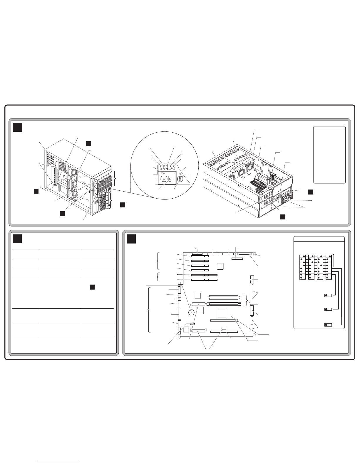
Cabinet
A
System and
I/O Board
Fan Module
Fan Assembly
Power Connector
DIMM Slots
Processor
Knockout for
External SCSI
Shelf 4: Flexible Disk Drive
Shevles
1 – 4
I/O Connectors
Rear of System Board
Non-Hot-
Swap Mass
Storage Cage
Hot-Swap Mass
Storage Cage
System
Board
Release
Screws
(2 of 4)
Pedestal Version
(Front View) (Rear View)
Rack Version
See
C
Shelves 2 & 3: Optional
Mass Storage
See
B
See
C
Optional
Redundant
Power Supply
I/O Connectors
See
1
2
C
PCI Slots
See
C
Hot-Swap HDD
Slots 1 – 6
See
D
Hard Disk
Activity
Overtemperature
Power
Reserved
Secure
Mode
Reset Keyboard
Lock
Power
On/Off/Sleep
Power
Indicator
Fan Fail
Front
Panel Display
Default Boot Order
1. IDE CD-ROM
2. FDD
3. SCSI A Bus
• SCSI Device ID 0
• SCSI Device ID 9
4. SCSI B Bus
• SCSI Device ID 0
• SCSI Device ID 9
5. PCI Slot P1
6. PCI Slot P2
7. PCI Slot P3
8. PCI Slot P4
9. PCI Slot P5
10.PCI Slot P6
RESET
System Board
Release Screw (1 of 4)
Power Supplies
1
2
3
4
5
6
1
2
3
4
5
6
Shelf 1: IDE CD-ROM Drive
6 PCI
Slots
Caution: Do not operate server for
more than 2 minutes with any cover
(including Power Supply Bays and
Disk Drives) removed. Processor will
shut down if overheated.
Mass Storage Device
Locations and Settings
B
Device
Standard
IDE CD-ROM
Standard
Hard Disk Drive
HP Accessory
9.1 GB HDD
HP Accessory
18.2 GB HDD
HP Accessory
36.4 GB HDD
Additional
SCSI device
Standard Dual
Channel SCSI
Controller
Location in order
of recommendation
Shelf 1
Shelf 2
Hot-Swap HDD
Slot 1, 2, 3, 4, 5, 6
6 Low-Profile,
3 Half-Height Drives,
or
mix LP/HH
Shelf 3
Embedded
Device Settings
Set to
Master (Default)
SCSI ID 0 (Default)
For additional HDD,
For SureStore,
SCSI ID 2
For DAT, SCSI ID 4
SCSI ID 7
See documentation with each device for further
configuration information.
See
D
Flexible Disk
Drive
PCI Slot 1
PCI Slot 2
PCI Slot 3
PCI Slot 4
Fan
Connector
SCSI A
SCSI B
32-bit
CMOS
Battery
Video
Configuration
Switch
IDE CD-ROM
System Board
Assembly
Release Screws (4)
3
2
1
0
PCI Slot 5
PCI Slot 6
64-bit
I/0
Connectors
Secondary
VRM
Primary
Processor Slot
Secondary Processor Slot
Primary VRM Primary Temperature Sensor (U51)
Secondary Temperature Sensor (U43)
Front Panel Connector
Power Connector
For Mass Storage
Optional Redundant
Power Supply
Connectors
Power Supply
Connectors
LAN
Keyboard
Mouse
Parallel
Serial
Connector
Management
Port
System and I/O Board
C
For additional information, see other side.
DIMM Slots
*
*
*
*
CPU
Speed
Test Only (7)
Password (6)
Clear Password
Config. Memory (5)
Clear Config. (CMOS)
ON
OFF
Configuration Switch
Switch 8 Off = 133MHz FSB
733
ON
OFFONOFFONOFF
1
2
3
4
5
6
7
8
667600533
Page 2
HP NetServer LC 2000 & LC 2000r Technical Reference Card
Audience Assumptions
This Technical Reference Card is for
trained service personnel. Hewlett-Packard
Company assumes you are qualified in the
servicing of computer equipment and trained
in recognizing hazards in products with
hazardous energy levels.
Electrostatic Discharge
To avoid catastrophic or hidden damage to
components, wear a wrist strap and use a
static-dissipative work surface connected to
the chassis when handling components. Use
an antistatic service kit, such as 3M
8501/8502/8505 or equivalent.
This information is subject to change without
notice and is provided without warranty.
© copyright 1999, Hewlett-Packard
For additional information, see other side.
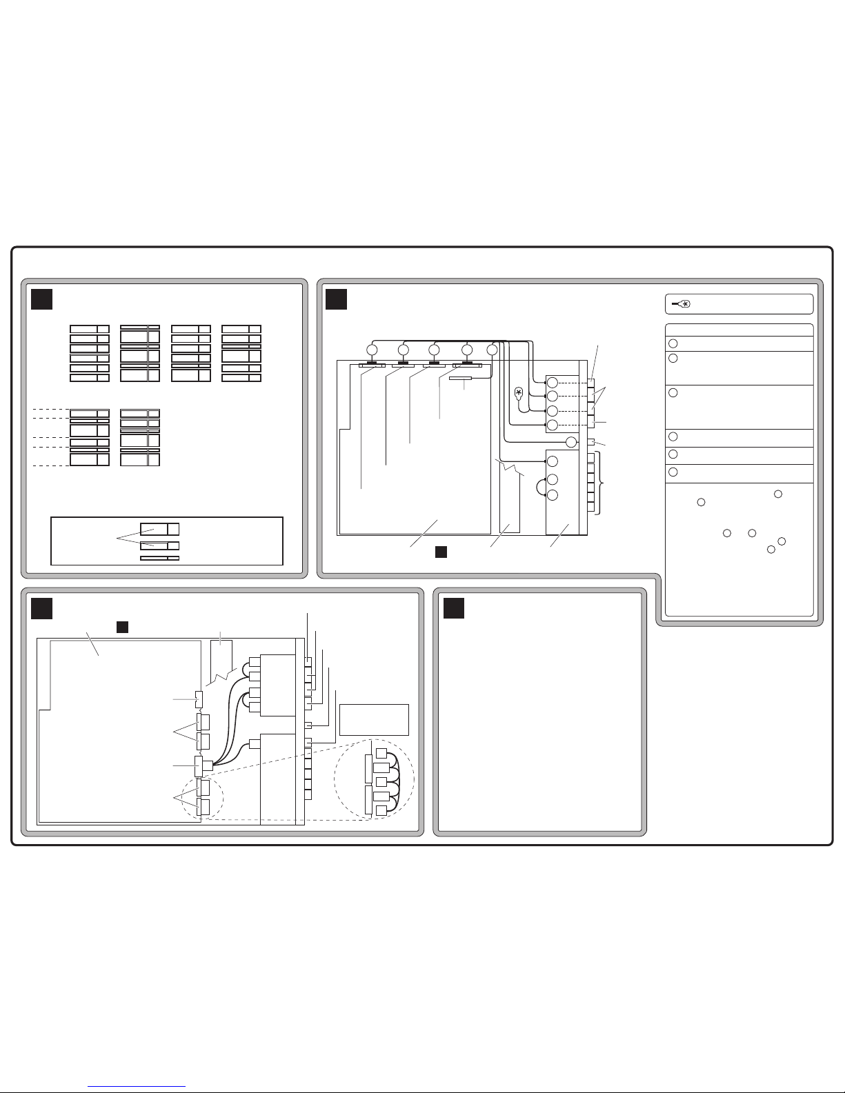
SCSI Hot-Swap HDD Configurations
Key
D
1.6˝ Half-Height (HH) drive
1˝ Low Profile (LP) drive
.5˝ Drive Spacer
2 LP-HH-2LP
9
8
1
0
2
9
8
3
2
1HH-4LP
0
3 HH
0
2
8
9
8
2HH-2LP
0
2
6 LP
9
8
3
2
1
0
HDD Slot
6
5
4
3
2
1
SCSI ID
HDD Slot
6
5
4
3
2
1
Alternating
HH-LP
9
3
0
2
Hot-Swap Mass Storage
Configurations
• Ensure hot-swap drives are
installed in lowest (pedestal)
or left-most (rack) slot first.
• Use only HP Ultra-2 (LVD)
SCSI 3.5-inch HDDs.
• You may mix or match Low
Profile (LP–1-inch) and HalfHeight (HH–1.6-inch) HHD.
• For rack-mounted models,
rotate diagrams 90˚ clockwise
SCSI ID
Shown Here
Power Supply Cabling
F
Fan Module (Removed)
System Board
Fan Module
Power Connector
C
P
4
P
5
P
4
P
5
P4
P4
P3
Mass Storage
Power Connector
Optional
Redundant Power
Supply Connectors
P1
P2
P5
P6
P1
P5
P2
P3
P1, P2, and P3 are
connected to power
supplies below/behind
P4 and P5
IDE CD-ROM Drive
Flexible Disk Drive
Front Panel
Display
Hot-Swap Mass
Storage Drives
Non-Hot-Swap Mass
Storage Units
Mass Storage Cabling
E
IDE CD-ROM
Connector
Fan Module
(Removed)
System Board
Front Panel
Connector
1
2
3 4
5
5
SCSI B
Connector
SCSI A
Connector
Flexible
Disk Drive
Connector
C
1
2
6
6
3
3
4
Mass Storage
Cage
IDE CD-ROM Drive
Flexible Disk
Drive
Front Panel
Display
Hot-Swap
Mass Storage
Drives
Optional
Non-HotSwap Mass
Storage Units
1
2
3
4
5
6
Cables
FDD Cable
Unterminated SCSI Cable from
System Board to Hot-Swap Bay
(See Notes 1 & 2).
Terminated SCSI Cable from System
Board to Common Tray Devices.
DO NOT CONNECT TO HOT-SWAP
BAY. (See Notes 1 & 2)
IDE CD-ROM Cable
Control Panel Cable
SCSI Cable for Hot-Swap
Note 1: Connectors on cables and
must be plugged into the
correct connector, as shown
on labeled cable-ends.
Note 2: Cables and are not
interchangeable. Cable is
unterminated, cable is
terminated. Data corruption
will occur unless cables are
connected as shown.
Note 3: Further details in the
Installation Guide.
3
2
3
2
3
2
Built-in SCSI Terminator
Service Information
Electronic Support Services
• Internet Web Pages http://www.hp.com/netserver
• Internet FTP ftp://ftp.netserver.hp.com
• CompuServe Library GO HPPC
• HP Navigator CD
Support Questions
• HP-Authorized Reseller
• CompuServe Discussion Forum GO HPPC
• US / Canada Phone Support 1-208-331-2767
• Europe Phone Support (+31-20) 581-3330
(Netherlands)
HP has offices in over 100 countries.
Check your local telephone directory.
G
HP Product No. D8514-80201, REV B, Sept. 1999
 Loading...