

Page 1

HP NetRAID Series User Guide
for HP NetRAID and HP NetRAID-1
Page 2

Notice
The information contained in this document is subject to change without notice.
Hewlett-Packard makes no warranty of any kind with regard to this material, including, but
not limited to, the implied warranties of merchantability and fitness for a particular purpose.
Hewlett-Packard shall not be liable for errors contained herein or for incidental or consequential
damages in connection with the furnishing, performance, or use of this material.
Hewlett-Packard assumes no responsibility for the use or reliability of its software on equipment that
is not furnished by Hewlett-Packard.
This document contains proprietary information that is protected by copyright. All rights are
reserved. No part of this document may be photocopied, reproduced, or translated to another
language without the prior written consent of Hewlett-Packa rd Company.
®
Novell NetWare
registered trademarks of Microsoft Corporation.
Hewlett-Packard Company
Network Server Division
Technical Marketing/MS 53U-FJ
5301 Stevens Creek Blvd.
P.O. Box 58059
Santa Clara, CA 95052-8059 USA
© Copyright 1997, Hewlett-Packard Company.
is a registered trademark of Novell, Inc. Windows NT
®
and Windows 95® are
Audience A ssumptions
This Installation and Configuration Guide is for the person who installs, administers, and
troubleshoots LAN servers. Hewlett-Packard Company assumes you are qualified in the servicing of
computer equipment and trained in recognizing hazards in products with hazardous energy levels.
i
Page 3

Contents
Introduction..........................................................................................................1
HP NetRAID and HP NetRAID-1 Adapter Features............................................ 3
A. Hardware Features........................................................................................ 3
B. RAID Management Features......................................................................... 6
C. Monitor Feature............................................................................................. 7
D. Check Consistency Feature..........................................................................7
E. Online Capacity Expansion Feature under Novell NetWare ......................... 8
F. Online Capacity Expansion Feature under Microsoft Windows-NT ............ 11
G. Alarm Feature............................................................................................. 14
H. Power Fail Safeguard Feature .................................................................... 14
I. Autorebuild Feature ...................................................................................... 15
NOS Compatibility and Driver Installation....................................................... 17
Overview.......................................................................................................... 17
Network Operating System Compatibility ........................................................ 18
Operating System Drivers and Utilities............................................................ 18
Installing Adapter Utilities................................................................................. 19
Windows NT: HP NetRAID Assistant................................................................21
Overview.......................................................................................................... 21
Starting HP NetRAID Assistant........................................................................ 21
A. HP NetRAID Assistant Menu Options ......................................................... 21
B. Toolbar Options........................................................................................... 26
C. Managing RAID With HP NetRAID Assistant.............................................. 27
NetWare, OS/2, SCO and Vines: HP NetRAID Config..................................... 29
Overview.......................................................................................................... 29
A. HP NetRAID Config NOS Starting Commands...........................................29
B. HP NetRAID Config Management Menu Options ....................................... 30
C. Configuring Arrays and Logical Drives........................................................ 33
D. Designating Drives as Hot Spares .............................................................. 39
E. Initializing Logical Drives............................................................................. 39
F. Using Logical Drives in the Operating System ............................................40
G. Formatting Physical Drives ......................................................................... 40
H. Exiting HP NetRAID Config......................................................................... 42
HP NetRAID Express Tools............................................................................... 43
Overview.......................................................................................................... 43
A. Specifications .............................................................................................. 43
B. Starting HP NetRAID Express Tools...........................................................43
C. Configuring Arrays and Logical Drives........................................................ 47
D. Formatting Physical Drives ......................................................................... 54
E. Exiting HP NetRAID Express Tools............................................................. 56
Troubleshooting................................................................................................. 57
Problem Solving...............................................................................................57
Monitor Alert List.............................................................................................. 58
ii
Page 4

BIOS Error Messages...................................................................................... 60
Other Error Messages ..................................................................................... 61
Questions and Answers................................................................................... 61
Audible Warnings............................................................................................... 63
Connector Pinouts............................................................................................. 65
High-Density 68-Pin SCSI Connector and P-Cable Single-Ended Cable
Pinout............................................................................................................... 65
Battery Backup Module.....................................................................................67
Charging the Battery Pack............................................................................... 67
Changing the Battery Backup Module ............................................................. 67
Battery Specifications ...................................................................................... 68
Changing DRAM Modules.................................................................................71
HP NetRAID Specifications...............................................................................73
Glossary.............................................................................................................. 75
iii
Page 5

Introduction
The HP NetRAID and HP NetRAID-1 adapters are high performance, intelligent PCI-to-SCSI host
adapters with RAID control capabilities. The HP NetRAID Series Installation and Configuration
Guide describes the installation and initial configuration of the adapters. This HP NetRAID Series
User Guide describes hardware, troubleshooting, configuration, and management fea t ures and
contains an extensive glossary of HP NetRAID terms and technologies.
The identical configuration and management utilities can be used with the HP NetRAID and HP
NetRAID-1 adapters. HP NetRAID Express Tools resides in the adapter’s BI OS and is independent
of the operating system. The two NOS-specific utilities are:
• HP NetRAID Assistant: use with Microsoft Windows NT
• HP NetRAID Config: use with Novell NetWare, IBM OS/2, SCO UNIX, and Banyan VINES
This guide contains installation instructions for these NOS-specific utilities.
Hardware topics in this guide include:
• Audible Warnings
• Connector Pi nouts
• Battery Backup Module (HP NetRAID only)
• Changing DRAM Modules
• Adapter Specifications
1
Page 6

Page 7

HP NetRAID and HP NetRAID-1 Adapter
Features
HP NetRAID and HP NetRAID-1 are high performance, intelligent PCI-to-SCSI host adapters with
RAID control capabilities. Up to three SCSI channels are available on the HP NetRAID adapter; one
SCSI channel is available on the HP NetRAID-1 adapter. Each channel can support a maximum of
six or eight Fast/Wide SCSI or Ultra/Wide SCSI devices.
This section describes each adapter feature. Features are grouped together by category, as follows:
A. Hardware Features
B. RAID Management Features
C. Monitors Feature
D. Check Consistency Feature
E. Online Capacity Expansion Feature under Novell NetWare
F. Online Capacity Expansion Feature under Microsoft Windows-NT
G. Alarm Feature
H. Power Fail Safeguard Feature
I. Autorebuild Feature
A. Hardware Features
The following hardware specifications apply to the HP NetRAID and HP NetRAID-1 adapters:
CPU
The adapters use the 32-bit Intel i960CA RISC processor running at 33 MHz. This processor directs
all functions of the adapter including command processing, PCI and SCSI bus transfers, RAID
processing, drive rebuilding, cache management, and error recovery.
Cache Memory
The HP NetRAID adapter has two SIMM sockets, using × 36 (72-pin) 60/70 ns SIMMs. The two
SIMMs are interleaved and operate in page mode. The standard configuration is 4 MB of cache
memory (a single SIMM is installed).
The HP NetRAID-1 adapter has one SIMM socket, using a single × 36 (72-pin) 60/70 ns SIMM.
The standard configuration is 4 MB of cache memory (a SIMM is installed).
The adapters cache support Write-Through or Write-Back caching for Write Policy, and ReadAhead, Normal, or Adaptive caching for Read Policy. The defaults are Write-Through and Adaptive.
Custom ASIC
This ASIC (Application Specific Integrated Circuit) provides PCI bus mastering with a burst data
transfer rate of 132 MB.
The ASIC handles data transfer between the PCI bus, the cache, and the SCSI bus. This ASIC
supports memory write and invalidate commands on the PCI bus. It also performs RAID parity
generation and checking in RAID levels 1, 3, 5, 10, 30, and 50.
3
Page 8

Onboard Speaker
The adapters have an onboard tone generator for audible warnings when system errors occur.
Audible warnings can be generated through this speaker. Refer to the sectio n Audible Warnings for
further information.
SCSI Bus
Each channel can support a maximum of six or eight Fast/Wide SCSI or Ultra/Wide SCSI devices,
depending on the HP system and enclosure used. Ultra/Wide SCSI support can be enabled by the
user for individual channels.
Channel
0
1*
2*
* HP NetRAID Only
• External connections requires a D3637C Cable. If the cable is not supplied with your system,
see HP’s Order Assistant for ordering information. Order Assistant is available on the Internet
at http://www.hp.com/go/netserver.
• External storage with the HP Storage System/6 only supports Fast/Wide SCSI devices.
• External storage with the HP Rack Storage/8 supports Fast/Wide or Ultra/Wide SCSI devices
(may be mixed).
Internal Connection External Connection
6
6
6
6 or 8
6 or 8
6 or 8
• Internal NetServer storage of six hot swap drives support Fast/Wide or Ultra/Wide SCSI
devices (may be mixed).
NOTE See HP Order Assistant for non-hot swap disk support. HP Order Assistant is
ava ilable on the Internet at http ://www.hp.co m/go /netserver.
Each channel supports Fast/Wide SCSI (at data transfer rates up to 20 MB/sec per channel) and
Ultra/Wide SCSI (at data transfer rates up to 40 MB/sec per channel).
SCSI Connectors
• HP NetRAID has three 68-pin internal high density conne ctors for SCSI channels 0, 1, 2
which support Ultra/Wide SCSI. HP NetRAID has one 68-pin external ultra/wide-highdensity connector for each of SCSI channels 0 and 1 which support Ultra/Wide SCSI with the
Rack Storage/8, or Fast SCSI for all other mass storage devices. One connector type at a time
can be used for channels 0 and 1.
• HP NetRAID-1 has one 68-pin internal high density conne ctor for SCSI channel 0 which
support Ultra/Wide SCSI and one 68-pin external ultra/wide-high-density connector for SCSI
channel 0. One connector type at a time can be used.
SCSI Termination
The adapters use active termination on the SCSI bus conforming to Alternative 2 of the SCSI-2
specifications. Termination enable/disable is automatic through cable detection.
4
Page 9

SCSI Firmware
The HP NetRAID Series firmware handles all RAID and SCSI command processing and also
supports the functions described in the following table.
Feature
Disconnect/Reconnect Optimizes SCSI Bus seek
Tagged Command Queuing Multiple tags to improve random access
Scatter/Gather Multiple address/count pairs
Multi-threading Up to 255 simultaneous commands with elevator sorting and
concatenation of requests per SCSI channel
Stripe Size Variable for all logical drives from 4 KB to 128 KB. Note: 128 KB
stripe is not supported with 4 MB of memory or less.
Rebuild Multiple rebuilds and consistency checks with user definable priority
Functions Supported by HP NetRAID Series Firmware
Description
Automatic Failed Drive Detection and Rebuild
The adapters firmware automatically detects and rebuilds failed drives, which can be done
transparently with hot spares.
Drive Roaming
The adapters have the ability to determine when disk drives have been physically moved from one
slot to another, as in a hot swap (on the same adapter).
Hot Swap Manual Replacement
The adapters support the manual replacement of a hot swap disk unit in the RAID subsystem without
shutting down the system.
Battery-backed Cache Memory (HP N etRA ID Only)
A battery module (on a mezzanine card) is supplied to provide backup power for the cache in case of
a power failure. This backup power prevents cache data loss.
The HP NetRAID Battery backup module protects the data handled by the HP NetRAID Adapter by
providing protection from power supply interruptions to the HP NetRAID cache memory. The HP
NetRAID Battery backup module monitors the voltage level of the DRAM modules installed on the
HP NetRAID card and supporting circuitry. If the voltage drops below a predefined level, the
Battery backup module switches the memory power source from the HP NetRAID card to the battery
pack attached to the HP NetRAID Battery backup module. As long as the voltage level is below the
predefined value, the HP NetRAID Battery backup module provides the memory refresh cycles
necessary to retain the contents of the HP NetRAID memory modules. If the voltage level returns to
an acceptable level, the HP NetRAID Module switches the power sources back to the HP NetRAID
adapter card. The battery supports 48-hours or greater retention for a standard 4 MB cache memory.
NOTE When using SNMP monitoring with the NetRAID-1 adapter, you may see
messages that the battery module is missing. Disregard these message, as the
NetRAID-1 adapter does not include a battery module.
5
Page 10

B. RAID Management Features
Major Options
The adapters provide on-the-fly RAID migration, allowing for almost limitless adaptability and
expansion of any logical drive while the system remains operational. Once the installation setup is
complete, you have three major options:
• Change, add or expand the configuration, e.g., RAID level, adding additional adapter cards,
or online expansion capability
• Recover from disk failure or instability (Rebuild)
• Monitor/check the configuration
RAID Management Features
The adapters provide the following RAID management features:
• Add drives to any Optimal RAID logical drive
• Convert from RAID 0 or 1 to RAID 1, 3, or 5 by adding a physical drive
• Change from a Degraded redundant logical drive to an Optimal RAID 0 logical drive
• Convert a RAID 5 logical drive to a RAID 3 logical drive
• Convert a RAID 3 logical drive to a RAID 5 logical drive
• Remove any physical drive from a logical drive (This action may require a change in RAID
level.)
• Change a RAID 1, 3, or 5 logical drive to a RAID 0 logical drive
• Online capacity expansion
For information on specific management functions, refer to the section Managing RAID With HP
NetRAID Assistant.
6
Page 11

Valid RAID Level Changes
To make practicable RAID level changes with HP NetRAID, observe the possible valid RAID level
changes listed in the following table when altering a physical drive or logical drive.
Existing RAID
Configuration
RAID 3 or RAID 5 Optimal RAID 3 or RAID 5 Optimal Expanding capacity
RAID 3 or RAID 5 Optimal RAID 0 Stopping parity
RAID 3 or RAID 5 Optimal RAID 0 Deleting a drive, or adding drives
RAID 3 or RAID 5 RAID 3 or RAID 5 Optimal If a drive fails, you can configure an
RAID 1 Optimal RAID 3 or RAID 5 Optimal Adding drives
RAID 1 Optimal RAID 0 Adding drives, or deleting a drive
RAID 1 Degraded RAID 0 If a drive fails, you can configure an
RAID 0 RAID 3 or RAID 5 Optimal Adding drives
RAID 0 RAID 1 Optimal Adding a drive
RAID 0 RAID 0 Adding drives
HP NetRAID Valid RAID Configuration Changes
Valid RAID
Configuration Change
Configuration Event
Optimal RAID 0 system.
Optimal RAID 0 system
C. Monitor Feature
Monitors send SNMP error messages to the HP NetRAID Assistant or the HP NetServer Assistant if
the disk array is not functioning p roperly.
Disk array monitors are provided for all operating systems. For information on SNMP agents (the
part of the system that performs information preparation and exchange on behalf of a client or
server) or server standalone, refer to HP NetServer Assistant. Monitors are installed with the
NetRAID utilities, and are included as part of the utility installation process.
Refer to your operating system information and the section Installing HP NetRAID Utilities for
information on installation. Refer to the section Troubleshooting for a list of monitor alerts.
D. Check Consistency Feature
Check Consistency ensures that parity data or mirroring is correct for the selected drives. RAID
levels 3, 5, 30 and 50 use an extra drive to store parity data blocks. Parity is checked between these
parity data blocks and the selected drives when you select this option. RAID levels 1 and 10 use
duplicate data drives; the duplicate data is verified.
NOTE It is strongly recommended that you run a regular consistency check (every 2 - 4
weeks) to ensure that good blocks on hard disk drives are reallocted. Bad blocks
which accumulate can cause rebuild failures is a drive fails.
7
Page 12

E. Online Capacity Expansion Feature under Nov ell NetWare
This section describes how users can take advantage of the NetRAID On-line Capacity Expansion
feature under the Novell NetWare operating system. The benefit for the user is that new storage
capacity can be added to the NetRAID controller and can be put on-line for use without rebooting
the server. Follow the steps outlined below to prepare a system for capacity expansion and then
expand a volume. This will provide the user with an easy process to add storage whenever needed.
Theory of Operation
Normally when a logical drive is created on an adapter, it presents this logical drive to the operating
system as configured. The drawback is that operating systems do not support expansion of a logical
drive where the partition and physical capacity are the same size. Adding capacity requires downing
server to reconfigure/restore an existing volume or adding the new storage space as a new volume.
Using the Capacity Expansion feature allows you to expand an existing volume without downing the
server.
Capacity Expansion is enabled on a per-logical drive basis. When enabled, the adapter presents to
the operating system a logical drive of 80 gigabytes. However, only a part of the 80 gigabyte logical
drive exists as actual physical storage. You configure volumes to only use the actual physical space
while the virtual space allows room for on-line expansion. For example, assume you have 1 logical
RAID-5 drive built from 4 physical hard disk drives of 9 gigabytes each; the result is 27 gigabytes of
actual storage space. If you enable Virtual Sizing for this logical drive, then the OS will see a
logical drive of 80 gigabytes, but only the first 27 gigabytes are real while the last 53 gigabytes are
virtual. Under NetWare, you create an 80 gigabyte partition, but within that partition you only
create volume(s) totaling 27 gigabytes or less. Since there is unused partition sp ace, the physical
storage of 27 gigabytes can be expanded on-line by adding another hard disk drive, but the partition
remains at 80 gigabytes.
Precautions
When using the Capacity Expansion feature, it is very important to not create volumes which exceed
the actual physical capacity. You must add up all volumes which may be using the physical storage
space such as a DOS volume, SYS volume, Hot Fix Area, and any user volumes. This is most
important if NetWare will be installed on the disk array (rather than a separate disk on an embedded
SCSI controller). During installation if the total physical capacity is exceeded during volume
creation, a NetWare abend and loss of the installation will occur. As long as the physical capacity is
not exceeded, the installation will be successful.
Although undesirable, NetWare will allow you to create volumes into the virtual space. This is
because during volume creation, NetWare only looks at the beginning of the volume and if there is
real storage space there, the volume will be created. However, when writing to this volume, you will
not be able to write beyond the physical limit and write errors will be generated when the physical
space is filled. Obviously you want to take care in when creating volumes in a partition containing
virtual space. Use the NetRAID Config module to check the actual physical capacity available and
be sure the total size of NetWare volumes do not exceed this value.
One other useful measure is to set the capacity alarms under NetWare so that warnings will be
generated when you approach the limit of a volume.
When using capacity expansion, you should use a single logical drive since capacity expansion is
controlled on a per logical drive basis. Reconstruction (e.g., adding a drive to an array) can only be
done on an array having a single logical drive. It is also important to plan future storage expansion
into your installation. This will ensure that you can easily expand capacity without need for
backup/restore operations or reconfiguration.
SFT-3 and Mirroring Users please not the following: Novell’s operating system which provides
system level fault tolerance by mirroring two system is not compatible with the capacity expansion
8
Page 13

feature. SFT-3 mirrors disk storage on a partition basis rather than a volume basis. Because of the
virtual space created within the partition, SFT-3 cannot successfully mirror the partitions. This
limitation also applies to regular mirroring (without SFT-3) of volumes. Novell is aware of this issue
but has not yet committed to providing a work around to this conflict. It is likely that a future version
of NetWare will address this issue. SFT-3 users may add storage capacity online without bringing
the two systems down if enough drives are added to create a new array and logical drive on a
NetRAID Series adapter. Under the Install module, NetWare can then scan for new devices and
detect the new logical drive.
Setting Up Your Array for Capacity Expansion
For NetWare installations, you will need to plan ahead and consider your storage use. Since
NetWare only permits one NetWare partition per logical drive, you need to make the NetWare
partition the size of the virtual logical drive in advance to be ab le to expand that volume. Under
NetWare, you cannot grow a partition, but you can add additional segments within an existing
partition. The added segments can be "joined " to be part of the same volume, or they can be made
separate volumes.
It does not matter if NetWare is already installed or not at this point assuming NetWare will reside
on a separate drive. If NetWare must be installed on the disk array, create a single logical drive with
Virtual Sizing enabled. Create a DOS partition of 500 megabytes or less for booting. NetWare
volumes can then be added after the DOS partition on the same logical drive. T he unused space on
the partition can be used later for capacity expansion. Be sure to follow the precautions above.
For this example assume that the OS is installed on a drive connected to the embedded SCSI channel
A. The following steps are necessary to prepare your array for capacity expansion.
1. Connect Drives to the HP NetRAID or HP NetRAID-1 adapter.
Connect physical drives to the adapter. Example: Assume there are four drives of 4 gigabytes each
connected to the adapter.
2. Configure the Adapter.
Configure your adapter and create a logical drive (this can be done in either NetRAID Assistant or in
Express Tools). If you create multiple arrays (groups of physical drives), you should know which
logical drive(s) will be designated for capacity expansion. You should only assign one logical drive
per array, otherwise the logical drive will not be reconstructable. Save your configuration. For this
example, assume the 4x4 gigabyte drives are configured as a single RAID 5 logical drive. This will
produce a logical drive with 12 gigabytes of real storage capacity.
It is important to initialize your logical drives; if the drives have been previously configured under
an OS, there can sometimes be residual partition/format information which can subsequently cause
misrepresentation of logical drives under NetWare’s Install module.
3. Enable Virtual Sizing.
If not already, enter Express Tools. Select the logical drive to be setup for capacity expansion by
selecting Objects/Logical Drives/Properties/Virtual Sizing and enabling Virtual Sizing. Virtual
Sizing is enabled on a per logical drive basis.
Note: Clearing a previous configuration does not reset the Virtual Sizing setting pr eviously used for
a logical drive; use the Reset to Factory Defaults in Express Tools to disable Virtual Sizing for all
logical drives or manually change the setting.
9
Page 14

4. Load NetWare and Create NetWare Partition.
Load NetWare and load the "Install" module. Select "Disk o ptions", then "Modify disk partitions
...". Create a NetWare partition on the logical drive (which has Virtual Sizing enabled); the partition
size will be 81,917 megabytes (80 gigabytes). Save the partition.
5. Create NetWare Volume.
Select "Volume options" from the "Install module". Add a segment up to the actual physical
capacity available; 12 gigabytes for this example. (If this was a NetWare sys volume, you would
want to use a smaller size of 2 gigabytes or size appropriate for your system and use the balance for
a user volume.) Save and mount the volume. At this point, the logical drive has a NetWare partition
of 80 gigabytes with a 12 gigabyte segment set as a volume. The 12 gigabyte volume is mounted
and ready for use. Be sure not to exceed the actual physical capacity when creating the 12 gigabyte
volume and include other uses such as a Hot Fix area, etc.
The new volume is now ready for use. Assume for this example the volume is called Vol1. Leave
the left over virtual storage space (81,917 megabytes minus 12 gigabytes) as unused. You c an write
data up to 12 gigabytes on the drive.
Reconstruction and New Volumes
After using the array created above, assume you are nearing the 12 gigabyte limit and you want to
add another 4 gigabyte drive to the existing array. This can be done without downing the server or
rebooting the system.
6. Add Capacity by Reconstr uction.
Load the NetRAID Config utility (megamgr.nlm module) under NetWare. Select "Advanced" menu,
"Reconstruct Logical Drive". Select the logical drive to reconstruct. The controller scans for new
drives. Select the drive to be added per screen instructio ns and enter the Reconstruct Menu. This
allows you to add the drive and reconstruct the 4 drive RAID 5 array to a 5 drive RAID 5 array.
Reconstruction is done in the background so there is no need to down the server. When
reconstruction finishes the logical drive now has 16 gigabytes available physical capacity. The
original 12 gigabyte volume Vol1 is still intact.
The reconstruction rate is about 80 to 180 megabytes per minute (depending on drive performance,
system loading, etc.). Count the capacity to be reconstructed as the number of physical drives
participating in the reconstruction times drive capacity.
7. Make the Added Capacity Available.
Return to the "Install" module. Select "Volume options". Add a new segment under the NetWare
partition. You can either make the added capacity a new volume or it can be part of the original
volume. If made part of the original volume, the original volume need not be dismounted. The new
segment size must be 4 gigabytes or less as this is the amount of added capacity (for this example).
Save changes. If the new capacity is part of an existing volume, it is mounted automatically (if the
existing volume was already mounted). If the new volume is separate, mount the volume. The new
capacity is now available for use.
When adding to an existing volume, be sure not to exceed the actual physical capacity available.
Existing Installations Without Virtual Sizing Enabled
If you already are using the NetRAID adapter without Virtual Sizing enabled, but now wish to add
capacity to an existing volume, you will be limited in your options. Here are the likely scenarios
when Virtual Sizing has not been enabled.
10
Page 15

Without Reboot
You can only add capacity as a new volume. You will need to add enough physical drives to cr eate
a new array and logical drive using NetRAID Config. Then under NetWare Install, you will need to
“Scan For New Devices”, and configure the new logical drive as a new NetWare volume.
With Reboot
If a reboot is acceptable, then the server can be downed, and Virtual Sizing enabled in Express
Tools. This assumes that you have not yet used the logical drive so that the 80 gigabyte partition can
be created. If the logical drive has already been partitioned and used, to enable volume expansion,
you will need to save data, enable Virtual Sizing, then repartition the drive and restore the data.
Now that volume can be expanded on-line whenever required.
F. Online Capacity Expansion Feature under Microsoft
Windows-NT
This section describes how users can take advantage of the NetRAID On-line Capacity Expansion
feature under the Microsoft NT operating system. The benefit for the user is that new storage
capacity can be added to the HP NetRAID and HP NetRAID-1 adapters and can be put on-line for
use without rebooting the server. Follow the steps outlined below to prepare a system for capacity
expansion and then add a volume. This will provide the user with an easy process to add storage
whenever needed.
Theory of Operation
Normally when a logical drive is created on the HP NetRAID or HP NetRAID-1 adapters, it presents
this logical drive to the operating system as configured. The drawback is that operating systems do
not support expansion of a logical drive where the partition and physical capacity are the same size.
Adding capacity requires downing server to reconfigure/restore an existing volume or adding the
new storage space as a new volume. Using the Capacity Expansion feature allows you to add a
volume without downing the server.
Capacity Expansion is enabled on a per-logical drive basis. When enabled, the controller presents to
the operating system a logical drive of 80 gigabytes. However, only a part of the 80 gigabyte logical
drive exists as actual physical storage. You configure volumes to only use the actual physical space
while the virtual space allows room for on-line expansion. For example, assume you have 1 logical
RAID-5 drive built from 4 physical hard disk drives of 9 gigabytes each; the result is 27 gigabytes of
actual storage space. If you enable Virtual Sizing for this logical drive, then the OS will see a
logical drive of 80 gigabytes, but the first 27 gigabytes are real while the last 53 gigabytes are
virtual. Since there is unused logical drive space, the physical storage of 27 gigabytes can be
expanded on-line, but the total logical drive remains at 80 gigabytes.
Precautions
When using the Capacity Expansion feature, it is important to not create volumes which exceed the
actual physical capacity. If you attempt to do this under NT, the format operation will fail. If you
extend an existing partition into virtual space, this will be detected upon rebooting. In either case, be
sure to use no more than the actual available physical capacity. Capacity of the logical drive can be
checked with the NetRAID Assistant under NT.
Setting Up Your Array for Capacity Expansion (OS on non-disk array driv e)
When using capacity expansion, you should use a single logical drive since capacity expansion is
controlled on a per logical drive basis. Reconstruction (e.g., adding a drive to an existing array) can
only be done on an array having a single logical drive. It is also important to plan future storage
11
Page 16

expansion into your installation. This will ensure that you can easily expand capacity without
backup/restore operations or reconfiguration.
It does not matter if NT is already installed or not at this point assuming NT will reside on a separate
drive. If NT must be installed on the disk array, see the information under “Operating System and
Data on Disk Array”. For this example assume that NT is installed on a drive connected to the
embedded SCSI channel A. The following steps are necessary to prepare your array for capacity
expansion.
1. Connect Drives to the Adapter.
Connect physical drives to the HP NetRAID or HP NetRAID-1 adapter. Example: Assume there
are four drives of 4 gigabytes each connected to the adapter.
2. Configure the Adapter.
Configure your adapter and create a logical drive (this can be done in either NetRAID Assistant or in
Express Tools). If you create multiple arrays (groups of physical drives), you should know which
logical drive(s) will be designated for capacity expansion. You should only assign one logical drive
per array, otherwise the logical drive will not be reconstructable. Save your configuration. For this
example, assume the 4x4 gigabyte drives are configured as a single RAID 5 logical drive. This will
produce a logical drive with 12 gigabytes of real storage capacity.
Note: It is important to initialize your logical drives; if the drives have been previously configured
under an OS, there can sometimes be residual partition/format information which can subsequently
cause misrepresentation of logical drives under the NT Disk Administrator.
3. Enable Virtual Sizing.
If not already, enter Express Tools. Select the logical drive to be setup for capacity expansion by
selecting Objects/Logical Drives/Properties/Virtual Sizing and enabling Virtual Sizing. Virtual
Sizing is enabled on a per logical drive basis.
Note: Clearing a previous configuration does not reset the Virtual Sizing setting pr eviously used for
a logical drive; use the Reset to Factory Defaults in Express Tools to disable Virtual Sizing for all
logical drives or manually change the setting.
4. Start NT and Enter Disk Administrator.
Start NT and enter the Disk Administrator. Here you will see the new logical drive shown as a
single unpartitioned/unformatted drive of 81,917 megabytes (80 gigabytes). Although there is only
12 gigabytes of real storage space on the logical drive, the Capacity Expansion feature creates a
virtual drive of 81,917 megabytes.
5. Partition and Format the Drive.
To use the new drive, you must first partition the drive. Create a partition equal or less than the real
storage capacity (for this example, 12 gigabytes where 1 gigabyte is 1024 cubed). Commit the
change and format the partition. Note: If the partition is larger than the real storage capacity, the
format operation will generate a message "Warning: NT was unable to complete the format".
The formatted drive is now ready for use. Assume for this example the drive is now E: and was
partitioned as a primary partition. Leave the left over virtual storage space (81,917 megabytes minus
12 gigabytes) unpartitioned. You can write data up to 12 gigabytes on the drive. NT will not allow
you to write beyond 12 gigabytes and loose any data.
12
Page 17

Reconstruction and New Volumes
After using the array created above, assume you are nearing the 12 gigabyte limit and you want to
add another 4 gigabyte drive to the existing array. This can be done without downing the server or
rebooting the system.
6. Add Capacity by Reconstr uction.
Add the new physical drive to the adapter by plugging it into an empty hot swap storage slot. Bring
up NetRAID Assistant under NT. Select the logical drive and the new physical drive. Then select
Logical Drive/Change Config/Add Capacity. This will reconstruct the current 4 drive RAID 5 array
to a 5 drive RAID 5 array. When reconstruction is complete, the real storage capacity will now be
16 gigabytes. Reconstruction occurs in the background, so the original 12 gigabyte volume will still
be available during the reconstruction process.
The reconstruction rate is about 80 to 180 megabytes per minute (depending drive performance,
system loading, etc.). Count the capacity to be reconstructed as the number of physical drives
participating in the reconstruction times drive capacity.
7. Partition and Format New Capacity.
When the reconstruction is completed, enter the Disk Administrator. The original drive is still
shown as E: and is 12 gigabytes. You can now select the unpartitioned area, and create a primary
partition of 4 gigabytes. Format the new partition, and for this example you will now have another
drive (say F:) of 4 gigabytes without rebooting. You can exit the Disk Administrator and begin use
of the new capacity on the F volume.
If it is required that expanded capacity and the original capacity share the same drive letter, this can
be done but will require rebooting NT. The added capacity must be partitioned as an extended
partition, then select the original and new (extended) partition. Use the selection "Extend Partition"
to make the two partitions share the same drive letter (E: for this example). You will need to reboot
NT before any part of E: becomes available again. If you accidentally enter more capacity than is
actually available, NT will detect the error upon rebooting as it will execute a check-disk operation
on the extended volume.
Operating System and Data on the Disk A rray
Sometimes it is desirable to have the OS and user data both reside on the disk array, either on the
same logical drive (one array) or on separate logical drives (two or more arrays). The advantage is
that the OS will reside on a redundant drive. Again, to reconstruct a logical drive it must be
configured as 1 logical drive on an array.
For the case where the disk array is used as the boot device and contains user data, Virtual Sizing
can still be used. The key limitation is that NT only allows a FAT boot partition size of 4 gigabytes
or less. The disk array can be configured with an array just for the boot partition/OS and another
array for user data. The second array/logical drive would be used for Virtual Sizing as detailed in
the above steps. For this case, the boot partition could not be used for capacity expansion.
If the OS and data need to be on a single array (and single logical drive), multiple partitions are
needed for capacity expansion. Enable Virtual Sizing for the logical drive. As in the above steps,
the logical drive will be shown with the virtual capacity of 81,917 megabytes. Create a FAT boot
partition of 4 gigabytes or less for the OS which will become the C: volume. Create a second
partition for the data which will become for example the D: volume. The remaining virtual capacity
can be used for expansion by creating additional partitions for new volumes as explained above.
13
Page 18

Existing Installations Without Virtual Sizing Enabled
If you already are using the adapter without Virtual Sizing enabled, but now wish to add capacity to
an existing volume, you will be limited in your options. Here are the likely scenarios when Virtual
Sizing has not been enabled.
Without Rebooting
Unless Virtual Sizing is used, NT does not recognize new logical drives unless rebooted. Any drive
(logical or physical) will not be seen under the Disk Administrator until rebooted.
With Reboot
If a reboot is acceptable, then the server can be downed, Virtual Sizing enabled in Express Tools,
and the on-line expansion process under NT can b e followed. This will allow a single drive to be
added to an existing array.
G. Alarm Feature
The adapters include an onboard tone generator to sound alarms and warnings. This alarm can be
enabled and disabled from the main menu. A list of audible alarm signals and their meanings is
located in the later section Audible Warnings.
H. Power Fail Safeguard Feature
One of the features of the HP NetRAID and HP NetRAID-1 adapters is reconstruction of an existing
array. Reconstruction is the process of modifying a RAID configuration by either adding a drive to
an existing array (e.g., capacity expansion) or migrating an existing array to a different RAID level
(e.g., changing from RAID 1 to RAID 5). Reconstruction should not be c onfused with “rebuilding”;
rebuilding is the process of recreating data on a replacement drive after a drive failure. Power Fail
Safeguard (PFS) allows the user to protect the disk array during the reconstruction process should a
power loss occur.
When a new array is initialized, the last one megabyte of each physical disk is reserved for use by
the adapter. Three blocks (sectors) are used to store configuration information and the remaining
area is used for the Power Fail Safeguard feature (the one megabyte of space is reserved even if PFS
is not enabled). When the PFS feature is enabled, the adapter uses the reserved space in the one
megabyte segment on each disk to temporarily store data which will be reorganized and written
during a reconstruction. Thus there will always be a copy of data which resides on disk during the
reconstruction process so there is no risk of losing any data. The data is reorganized to correspond
with the change in disk/RAID level associated with the reconstruction operation. Without PFS
enabled, the adapter reads data from the original set of disks into memory and then writes the
reorganized data to the disks. Because the d a ta tr ansitions through memory, there is a brief exposure
where data could be lost if a power loss occurs. The reconstruction process is not able to recover
data from memory after a power loss (even with battery backup). Enabling PFS will protect the
reconstruction process from any data loss in the event of a power failure. With or without PFS
enabled, a reconstruction will restart automatically where it was interrupted by a power failure.
Although PFS will protect the reconstruction operation, the re will be a decrease in reconstruction
performance. When PFS is enabled, the reconstruction time will increase by a factor of about 2.5
times due to the extra overhead of always having data saved on disk. However, there will be no
affect on normal array performance (i.e., no reconstruction is active) with PFS enabled. A typical
reconstruction time for a 4 drive RAID 5 array using 2-gigabyte disks to a 5 drive RAID 5 array is
about 90 minutes with PFS disabled and no other data transfers. With PFS enabled, the same
reconstruction requires about 230 minutes.
14
Page 19

PFS is enabled/disabled through either the NetRAID Express Tools or NetRAID Config utilities.
The default setting is disabled. Since there is only a performance penalty during the reconstruction
operation itself, it is recommended to enable the feature unless there are some rigid time constraints
on reconstruction activities.
I. Autorebuild Feature
The Autorebuild feature detects the replacement of a failed disk drive and automatically rebuilds
onto it the data that was on the failed disk. For Autorebuild to occur, all of the following conditions
must be satisfied:
• The HP NetRAID adapter BIOS firmware is version A.02.00 or later.
• Autorebuild was enabled in HP NetRAID Express Tools for the adapter controlling the failed
drive.
• The failed drive was replaced with a good drive in the SAME physical slot as the failed drive.
• The replacement drive capacity is at least as large as the failed drive capacity.
To enable the Autorebuild feature in HP NetRAID Express Tools, do the following:
1. Restart the NetServer.
2. When the following prompt appears, immediately press <Ctrl> <m> to start HP NetRAID
Express Tools.
Option: Experienced users may press <Ctrl> <M> for HP NetRAID
Express Tools now.
Alternatively, you may press <Ctrl> <m> while the following message is flashing:
Firmware Initializing
3. When the system stops scanning, HP NetRAID Express Tools immediately starts and
displays the Management menu. Choose the Objects option from it.
4. From the Objects menu, choose Adapter. If more than one HP NetRAID or HP NetRAID-1
adapter is installed in the NetServer, the Adapter Selection box appears; select the desired
adapter.
5. The Adapter menu lists Auto Rebuild in its Disabled default state. Choose Auto Rebuild, and
then enable it.
6. If Autorebuild must be enabled on another adapter, press ESC to back up to the Objects
menu. Then repeat Steps 5 and 6 for that adapter.
7. When all adapters have Autorebuild enabled, press ESC repeatedly to back up to the
Management menu.
8. To exit HP NetRAID Express Tools, press ESC at the Management menu display. Choose
Yes at the prompt. You must then reboot the NetServer.
15
Page 20

Page 21

NOS Compatibility and Driver Installation
Overv iew
HP NetRAID and HP NetRAID-1 are SCSI RAID adapters that include utilities to manage and
configure RAID subsystems; both adapters use the same utilities. This HP NetRAID Series User
Guide provides instructions in using the adapters to manage Redundant Arrays of Independent
Disks. For instructions in configuring physical drives or logical drives, refer to the HP NetRAID
Series Installation and Configuration Guide (part number 5965-2467).
Functions not shared by each of the three HP NetRAID utilities are listed in the following table.
(Functions common to each utility are not listed.)
Defaults
Function/Selection
Save/Load Config from File X
Reset to Default Settings X
Write Policy Write Through X X X
Read Policy Adaptive X X X
Cache Policy Cached X X X
Stripe Size 8 KB X X X
Alarm Control Enabled X X X
Rebuild Rate 50% X X X
Power-On Rights All X
Disk Spin Up Timings Automatic X X
Auto Rebuild Disabled X
BIOS Enable/Disable Enabled X
Ultra/Wide SCSI Enable/Disable Disabled X
Cache Flush Timings 4 seconds X
Initiator ID 7 X
Virtual Sizing Disabled X
Synchronous Negotiation Enabled X
SCSI-2 Command Tagging Enhanced X
Diagnostics X
View/Add/Delete Config X X
Power Fail Safeguard Disabled X X
SCSI Termination Wide X X
Battery Functions (HP NetRAID only) X X
Channel Activate/Deactivate Activated X
Add Capacity XX
View Log X
Print Config X
(if applicable)
HP NetRAID
Express Tools
HP NetRAID
Config
HP NetRAID
Assistant
Comparison of Adapter Utilities and Available Functions
17
Page 22

Network Operating System Compatibility
There are two network operating system management utilities that are used to configure and manage
the HP NetRAID and HP NetRAID-1 subsystems.
• HP NetRAID Assistant, an object-oriented Graphical User Interface (GUI) utility.
• HP NetRAID Config, a text-based RAID configuration utility.
Refer to the following table to determine which utility to use with your network operating system.
HP NetRAID Config
Banyan VINES 6.0, 7.0
IBM OS/2 2.11, 2.11SMP, Warp SMP
Novell NetWare 3.x, 4.xx, 4.xx SMP, SFTIII 4.1
SCO ODT 3.0, MPX 3.0, Open Server 5.0
Adapter Management Utilities and Respective Operating Systems
HP NetRAID Assistant
Windows NT 3.5x, 4.0
HP NetRAI D A ssistant
HP NetRAID Assistant is an object-oriented GUI RAID management utility on the HP Navigator
CD. HP NetRAID Assistant also runs under Microsoft Windows NT 3.5x and 4.0, and allows you
to control and monitor the status of hard disk drives, locally or over a network with several servers.
For instructions on configuring Physical Devices and Logical Devices, refer to the HP NetRAID
Series Installation and Configuration Guide.
HP NetRAID Config
HP NetRAID Config is a character-based, non-GUI utility that configures and manages RAID
systems. HP NetRAID Config runs under the following operating systems listed in the above table.
HP NetRAID Express Tools
A third utility used to manage the HP NetRAID subsystem is HP NetRAID Express Tools, a textbased configuration utility contained in the adapter firmware, and therefore is independent of any
operating system. HP NetRAID Express Tools contains some advanced manage ment and diagnostic
utilities that are not available with HP NetRAID Assistant or HP NetRAID Config. For information
on using this utility, refer to the section HP NetRAID Express Tools.
Operating System Driv ers and Utilities
Consult with the Hewlett-Packard World Wide Web site or your local HP dealer for compatibility of
your adapter with the most current versions of the network operating systems listed in the preceding
table.
18
Page 23

Refer to the following table for filenames of drivers and utilities specific to your NOS.
Network Operating
System
Banyan VINES 6.x, 7.0 Driver.o megamon megaconf
IBM OS/2 mraid.add monitor.cmd megaconf.exe
Windows NT mraidnt.sys
NetWare 3.1x Mega3_1x.dsk
NetWare 4.1x
NetWare ASPI
SCO Unix, OpenServe amird amirdmon megamgr
Network Operating Systems and Respective Driver and Utilities Files
*NOTE For Windows NT, the monitor function is embedded in the HP NetRAID
Assistant utility.
Drivers Monitor Utilities
Mega4_xx.ham
Mega4_xx.ddi
Mega4xx.dsk
Mega4xx.ddi
Megaspi.dsk
Megaspi.ddi
Installing Adapter Utilities
Configuration
Utilities
*
Megamon.nlm Megamgr.nlm
nraid.exe
After the HP NetRAID or HP NetRAID-1 adapter and your Network Operating System have been
installed, use the following instructions to install adapter utilities software for your specific Network
Operating System.
Banyan VINES 6.0, 7.0
1. To install the adapter drivers and utilities, please refer to the HP NetRAID Ba nyan driver
installation instructions in the Banyan VINES NOS installation guide. The utilities are
installed automatically with the driver.
2. After completing the driver installation, you may run the megamon utility from the
background to monitor the status of adapter activities.
3. After completing the driver installation, you may run the megaconf utility from the
foreground to configure the adapter resources on a limited scale.
IBM OS/2 2.11, 2.11 SMP, and Warp SMP
1. Open a command prompt window.
2. Type the drive path where you want to install the drivers.
3. Type "cd\" and press Enter.
4. Type "md HP NetRAID" and press Enter.
5. Type "cd HP NetRAID" and press Enter.
6. Type "copy <d>:\*.*" and press Enter (<d> is the drive letter of the floppy disk drive).
19
Page 24

7. Type "mon" from the HP NetRAID directory to run the monitor utility. Type "megaconf.exe"
from the HP NetRAID directory to run the configuration utility.
Microsoft Windows NT 4.0
1. Select "Start" from the taskbar.
2. Select "Run" from the "Start" menu.
3. Type "<d>:\setup" at the "Open:" prompt (<d> is the drive letter of the floppy disk drive).
4. Follow the onscreen instructions.
Microsoft Windows 3.5x
1. Select "File/Run" from the Program Manager.
2. Type "<d>:\setup" at the "Run" prompt and click "OK" (<d> is the drive letter of the floppy
disk drive).
3. Follow the onscreen instructions.
Novell NetWare 3.x, 4.xx, 4.xx SMP, SFT III 4.1
1. Exit to the DOS prompt.
2. Insert the floppy diskette containing the HP NetRAID Config utility.
3. Type “Copy <d1>:\*.nlm <d2>:\nwserver” and press the “Enter” key, where <d1> is the
drive letter for the floppy drive and <d2> is the hard disk where NetWare is installed.
4. To load the HP NetRAID Config utility, type “load <d2>:\nwserver\megamgr.nlm” and press
“Enter” at the NetWare command prompt.
SCO ODT 3.0, MPX 3.0, and Open Server 5.0
1. Please refer to the HP NetRAID SCO driver installation instructions in the SCO NOS
Installation Guide to install the adapter drivers and utilities. The utilities install automatically
with the driver.
2. After the driver installation is complete, the amirdmon utility is automatically run when the
system enters multi-user mode.
3. After the driver installation is complete, you may run the megamgr to configure the adapter
resources on a limited scale.
20
Page 25
Windows NT: HP NetRAID Assistant
A
Overv iew
HP NetRAID Assistant is an object-oriented GUI RAID management utility that runs under
Microsoft Windows NT on a server. HP NetRAID Assistant allows you to control and monitor the
status of hard disk drives, locally or over a network with several servers. For instructions on
configuring Physical Devices and Logical Devices, refer to the HP NetRAID Series Installation and
Configuration Guide.
This section describes:
A. HP NetRAID Assistant Menu Options
B. Toolbar Options
C. Managing RAID with the HP Ne tRAID Assistant
Starting HP NetRAID A ssistant
To start HP NetRAID Assistant, click on the HP NetRAID icon in the Windows Program Manager.
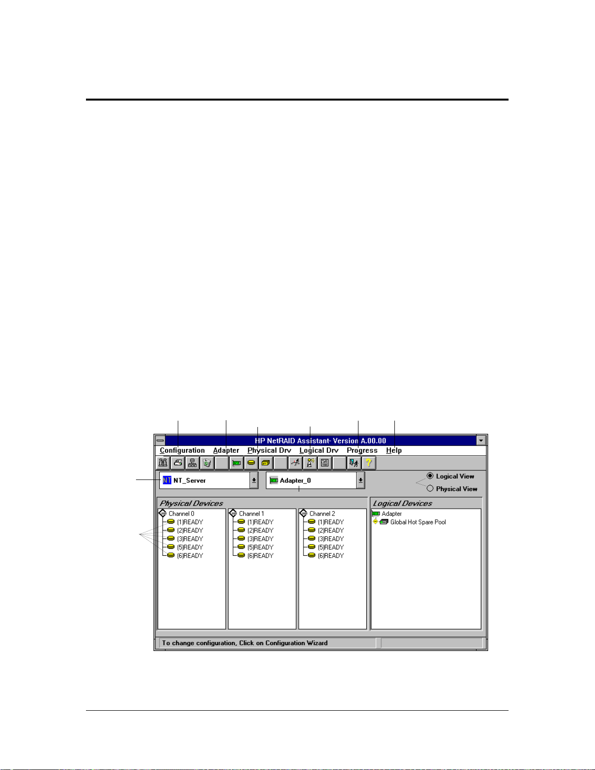
A. HP NetRA ID A ssistant Menu Options
HP NetRAID Assistant offers several menu options to assist you in configuring and monitoring
RAID systems. The menu options are listed below in the order they appear on the HP NetRAID
Assistant menu bar, from left to right.
Server
Selector
Physical
Drives
Configuration
Menu
dapter
Menu
Physical
Drive
Menu
Logical
Drive
Menu
Adapter Selector
HP NetRAID Assistant Main Menu
Progress
Menu
Help
Menu
Toggle
Between
Views
21
Page 26

NOTE Since the HP NetRAID-1 is a single channel adapter, the
HP NetRAID Assistant Main Menu Screen for HP NetRAID-1 contains only
Channel 0 information. Channel 1 and Channel 2 columns do not exist.
Config Menu Options
The following Configuration menu options will assist you in configuring the RAID.
• Wizard: The Wizard performs an Automatic or Custom Configuration to suit your needs.
The Automatic Configuration allows HP NetRAID Assistant to automatically configure the
RAID subsystem arrays, logical drives, and parameters. The Automatic Configuration default
setting is RAID 5.
The Custom Configuration option allows you to specify the arrays, logical drives, and
parameters that you want.
• Display: Displays the current configuration properties:
◊ Logical drives properties: State, RAID Type, Write Policy, Read Policy, Stripe Size,
Number of Stripes, Size (in MB)
◊ Physical drives properties: Rank, Channel, and Target (SCSI)
• Print: Prints a hardcopy of the current configuration display.
• Save: Saves the current configuration. A dialogue box prompts you to give your
configuration a file name with a .cfg extension.
• Load: Loads a previously saved configuration. A dialogue box prompts you to choose your
configuration from among .cfg files in the directory.
• Clear Configuration: Select this option to erase the current configuration information from
the adapter’s non-volatile memory. The current RAID configuration becomes invalid after
you select this option. This option should be used only when configuring a new system.
• Exit: Select this option to quit HP NetRAID Assistant. You cannot exit if disk operatio ns are
ongoing.
NOTE New configurations are not sa ved when exiting unless you first select the Save
Configuration option.
Adapter Menu Options
The options on the HP NetRAID Assistant Adapter menu are described below.
• Flush Cache: If the adapter must be powered down rapidly, you must flush the contents of
the cache memory to preserve data integrity. Perform a normal shutdown sequence for your
OS/NOS.
• Performance Monitor On/Off: Click the left mouse button on a drive icon and select
Performance Monitor to display a graphic representation of drive performance. You can
choose different logical drives, the type of graph, and the screen arrangement from the
Performance Monitor menus.
• Properties: Displays the adapter properties, including the firmware and BIOS versions, the
rebuild rate, and cache memory size.
22
Page 27

• Rebuild Rate: This option allows you to set the RAID rebuild drive rate for rebuilding a
failed drive. The rebuild rate determines the percentage of system resources devoted to the
rebuild. A 100% rebuild rate means that 100% of the system’s resources are applied to the
rebuild, leaving no resources available for other tasks until the rebuild completes. The default
rebuild rate is 50%.
• Rescan: The currently selected adapter rescans its SCSI channels to make sure that all drive
configuration information is current.
• View Log: Selecting this menu option displays the contents of the View Log File, which
records adapter activities and conditions such as battery backup charge (HP NetRAID only),
logical drive properties, and changes to configurations along with the date and time changes
are made.
• Alarm Control: There are two onboard tone generator settings, described below.
◊ Enable/Disable Alarm: Choose this option to enable or disable the onboard tone
generator. The default setting is Enabled.
◊ Silence Alarm: This setting stops the alarm when it goes off. To silence a sounding
alarm, choose Alarm and Silence.
Physical Drives Menu Options
The physical drive menu options are described below.
• Rebuild: To rebuild one or more failed disk drives, choose the Rebuild option from the
Physical Drv Menu. Select Cancel to stop the rebuild process at any time. The drive will
return to its original status before the rebuild began. A RAID 1, 3, 5, 10, 30 or 50
configuration has built-in redundancy. If a drive in one of these RAID groups fails, the RAID
subsystem continues to work but no additional redundancy is provided. Another drive failure
will bring the system down. Rebuilding the failed drive replaces and adds it into the RAID
system. The rebuild process can take place while the RAID system is still running, although
performance may be affected.
• Format: Choose the Format option from the Physical Drv Menu only to low-level format one
or more physical drives. Since most SCSI disk drives are low-level formatted at the factory,
this step is usually not necessary. You typically must format a disk if:
◊ The disk drive was not low-level formatted at the factory
◊ There is an excessive number of media errors detected on the disk drive
NOTE You do not need to use the Format option if you simply want to erase existing
information on your hard drives, such as a DOS partition. That information is
erased when you initialize the logical drive(s). Hewlett-Packard drives are
factory-formatted.
• Change Status: Select this option from the Physical Drv Menu to change the status of the
following functions:
◊ Make Online: Puts the drive online and available to the adapter
◊ Make Offline: Puts the drive offline and unavailable to adapter
◊ Spin Up: Sets the method and timing for spinning up the hard disk drives
◊ Spin Down: Sets the method and timing for spinning down the hard disk drives
23
Page 28

◊ Make Hot Spare: Click first on the drive icon of the drive you want to be the hot spare
• Properties: Choose this option from the Physical Drv Menu to display physical drive
properties of a selected drive. The properties include Device Identification, Device
Attributes, and Device Error.
Physical Drive Right Mouse Button Menus
When the Physical Devices box is set to either Physical View or Logical View, clicking on
the right mouse button opens the Physical Drive Menu. To access this menu, place the mouse
pointer on the icon of the physical drive and click the right mouse button. The following
popup menu options appear.
• Rebuild
• Abort Rebuild
• Format
• Tools
◊ Make Online
◊ Make Hot Spare
◊ Fail Drive
◊ Spin Down*
◊ Spin Up*
◊ Rewind*
◊ Eject*
◊ Erase*
• Firmware Download*
• Remove
• Properties
* not available
Logical Drives Menu Options
The logical drive options are described below.
•Initialize:
CAUTION HP NetRAID Assistant allows you to initialize a drive at any time. Make sure
that the drive being initialized does not hold live data. All data will be lost.
Logical Drives are initialized in one of two ways:
1. From the Logical Devices box of the main screen, select the logical drive(s) to be initialized,
and choose Initialize.
or
2. Drag the icon of the logical drive you want to initialize and drop it onto the Initialize icon.
NOTE If you have inadvertently reset your configuration, you can recover it by
immediately re-configuring the physical drives involved into the exact same array
and logical drive structure in which they had been, and by saving the
configuration without initializing.
24
Page 29

• Check Consistency: Ensures that parity or mirroring is correct for the selected drives. Click
on the drive to be checked (LD0-LD7). RAID levels 1, 3, and 5 use mirroring or parity to
store parity data blocks. Parity or mirroring is checked between these parity data blocks and
the selected drives when you select this option.
Check consistency should be run if the system shuts down irregularly, e.g., if the system
hangs or suffers a power failure. It is also recommended to run consistency checks every 2-4
weeks to ensure that bad blocks on the disk drive are mapped out. (See the “Check
Consistency Feature.”) Check consistency will always remedy inconsistencies. Check
consistency will only fail because firmware could not complete parity and data writes due to a
power-failure or a system hang, or because the logical drive degraded or failed due to the
physical drives going offline.
• Properties: Displays the logical drive properties of the selected logical drive. Each logical
drive can be displayed by selecting the Previous or Next buttons.
• Change Config: Select the logical drive or drives to change, then click on Change Config
and the preferred Change Config option. You must also initialize these drives.
◊ Cache: This parameter specifies read cache mode during data transfers involving the
current logical drive.
∗ Direct: Direct I/O specifies only repeated reads to same locations are cached.
∗ Cached: Cached I/O specifies that all reads are cached.
◊ Read: This parameter enables the SCSI Read-Ahead feature for the logical drive.
∗ Normal: Specifies that the controller does not use Read-Ahead for the current logical
drive.
∗ Read-Ahead: Specifies that the adapter uses Read-Ahead for the current logical
drive.
∗ Adaptive Read-Ahead: Specifies that the adapter begins using Read-Ahead if the
two most recent disk accesses occurred in sequential sectors. This is the default
setting.
◊ Write: This parameter sets the cache write policy. You can set the write policy to Write-
Back or Write-Through. Write-Through caching has a data security advantage over
Write-Back caching, whereas Write-Back caching has a performance advantage over
Write-Through caching.
∗ In Write-Back caching the adapter sends a data transfer completion signal to the host
when the adapter cache has received all the data in a transaction.
∗ In Write-Through caching, the adapter sends a data transfer completion signal to the
host when the disk subsystem has received all the data in a transaction. Write-Through
is the default setting.
◊ RAID Level: This option allows you to set a valid RAID level.
◊ Add Capacity: Use this option to add capacity to the logical drive.
Logical Drive Right Mouse Button Menus
When the Logical Devices box is set to Logical View, clicking on the right mouse button opens a
quick-access Logical Drive Menu. To access this menu, place the mouse pointer on a logical drive
icon and click the right mouse button. The following popup menu options appear.
25
Page 30
• Initialize
• Check Consistency
• Change Policy
• Advanced Menu
◊ Change Config (changes RAID level only)
◊ Add Drive
◊ Virtual Sizing
• Properties
Progress Menu Options
Using the Windows option, you can access and view the following utility monitors:
• Rebuild Progress
• Initialize Progress
• Check Consistency Progress
• Reconstruction Progress
• Performance Monitor
Help Menu Options
The Help Menu option yields the following choices.
• Help: Accesses the Help Menu for assistance.
• About: Provides informatio n about the version of the adapter you are running.
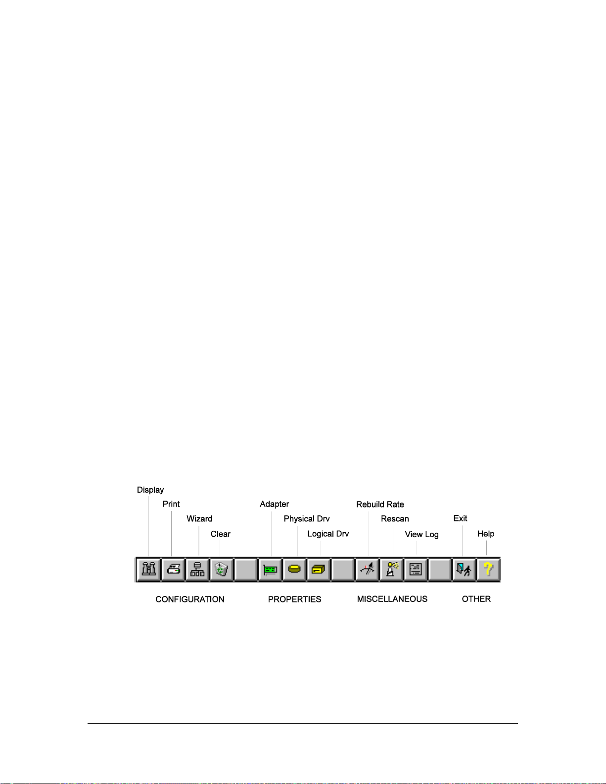
B. Toolbar Options
The toolbar icons are separated into four catego ries of functions: Configuration, Properties,
Progress, and Other, organized from left to right. They provide shortcuts to access the menu options
listed above each category in the following illustration.
HP NetRAID Assistant Main Menu Toolbar Options
26
Page 31
C. Managing RAID With HP NetRA ID A ssistant
Procedur es for perfor ming some of the most common RAID management functions are d escribed in
this section. Many of the adapter’s management functions can be performed using the drag-and-d rop
feature of the graphical interface in HP NetRAID’s Management Menu.
Rebuilding a Failed Physical Drive
The data of a failed physical drive will automatically be rebuilt onto another drive that is standing by
as a hot spare.
If you do not have a hot spare standing by, you will need to rebuild the failed drive or a drive that is
in the Ready state. Rebuild a drive by following these steps:
1. In the Physical Devices box, use the mouse pointer to highlight the physical drive icon.
2. From the Physical Drv Menu, choose Rebuild.
If you want to physically replace the failed hard drive with another hard drive, refer to your
NetServer's user instructio ns for directions on replacing hard d rives.
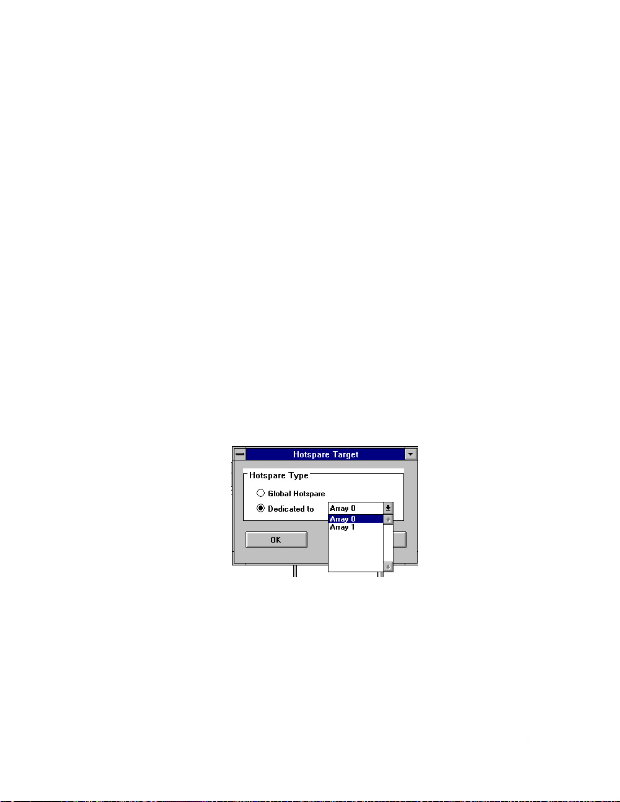
Adding a Hot Spare
With at least one drive in the Ready state, drag a Ready drive icon to the Global Hot Spare Pool
icon.
Hot Spares can be Global, i.e., available to every array, or Dedicated, i.e., available only to a
specified array. To make a Dedicated Hot Spare, from the main menu highlight the Ready drive and
select Make Hot Spare from the Physical D rv Menu. A dialogue box opens, prompting you to
choose to make the hot spare global (available to all arrays) or dedicated (available only to a
specified array). To make a Dedicated Hot Spare, click on the Dedicated Hot Spare selection and
select from the pulldown menu the array to which you want to dedicate the hot spare; then click OK.
Dedicated Hot Spare Target Selection Box
27
Page 32

Changing RAID Levels
RAID levels can be changed using a drive in the Ready state in one of two ways:
• From the Logical Drv Menu of the HP NetRAID Assistant
1. Select Logical View.
2. Highlight the logical drive you want to change from the Logical Devices box on the
right side of the screen.
3. Select Logical Drv, Change Status, RAID Level. The Change RAID Level dialogue
box opens.
4. Select your new RAID Level from the levels available for the new logical drive
configuration.
5. Select Apply. The Reconstruction Progress of the logical drive rebuild is displayed in
a message box and in the Logical Devices box.
• By drag and drop, moving the icon of a physical drive in the Ready state from the Physical
Devices box into a logical drive icon in the Logical Devices box. To change RAID levels of
logical drives by using the icons, at least one physical drive must be in the Ready state.
1. Drag the icon of a physical drive in the Ready state from the Physical Devices box into a
logical drive in the Logical Devices box.
2. A dialogue box will prompt you to select a new RAID level from those available in the
pulldown menu.
3. Click Apply. The logical drive you are changing will begin to Reconstruct.
NOTE Once started, reconstruction cannot be stopped.
Re-configuring Array s and Logical Drives
If you want to re-configure a configuration in which all physical drives are Online or hot spares, you
must clear the configuration and create a new configuration, preferably with the Custom
configuration.
You may add Ready physical drives to an existing configuration by using the RAID Configuration
Wizard.
Changing Logical Drive Parameters
To change logical drive parameters via the HP NetRAID Assistant Logical Drv Menu options, refer
to the previous section logical drives Menu Options.
Taking a Drive Offline/Online
A NetServer physical drive can be taken offline or put online in one of two ways:
• Manually, by removing or inserting the di sk drive by hand from a NetServer hot swap bay.
• As a menu selection, by highlighting the drive with the mouse poi nter and selecting Physical
Drv Menu, Change Status, M ake Offline or Make Online. (Only a Failed drive can go online
in this way. To put a Ready drive online, you must use the Configuration options.)
Making a drive Offline will put the drive into a Failed state.
28
Page 33

NetWare, OS/2, SCO and Vines: HP NetRAID
Config
Overv iew
HP NetRAID Config is a character-based, non-GUI utility that configures and monitors RAID
systems. HP NetRAID Config runs under the following operating systems:
• Novell NetWare 3.x, 4.xx, 4.xx SMP, SFTIII 4.1
• Banyan VINES 6.0 and 7.0
• IBM OS/2 Server 2.11, 2.11 SMP, and Warp SMP
• MS-DOS 3.2 or later
• SCO ODT 3.0, MPX 3.0, and OpenServer 5.0
NOTE These instructions in using HP NetRAID Config refer specifically to the Novell
NetWare network operating system. Specific features may not be available in all
network operating systems, and the exact location of specific menu options may
vary.
This section describes the following functions:
A. HP NetRAID Config NOS Starting Commands
B. HP NetRAID Config Management Menu Options
C. Configuring Arrays and Logical Drives
D. Initializing Logical Drives
E. Formatting Physical Drives
F. Exiting HP NetRAID Config
A. HP NetRA ID Config NOS Starting Commands
To start HP NetRAID Config, make sure the program file is in your file path and type the command
corresponding to your network operating system, as listed in the following table.
Operating
System
NetWare load megamgr
OS/2 megaconf
SCO UNIX megamgr
VINES 6.0, 7.0 megaconf
HP NetRAID Config
Starting Commands
29
Page 34

B. HP NetRAID Config Management Menu Options
The Management Menu options are explained below.
NOTE These instructions in using HP NetRAID Config refer specifically to the Novell
NetWare network operating system. Specific features may not be available in all
network operating systems, and the exact location of specific menu options may
vary.
Configure
Choose the Configure option to select a method for configuring arrays and logical drives. Refer to
Configuration Methods below for instructions.
Initialize
CAUTION Initializing logical drives erases all data on the physical drives.
Choose this option from the HP NetRAID Config Management Menu to initialize one or more
logical drives. This action typically follows the configuration of a new logical drive. To select the
drive to initialize, press the spacebar. To select all the drives, press F2. To initialize the selected
drive(s), press F10.
To cancel initialization once you have started it, press Esc.
Objects Menu
Objects
Choose the Objects option to access the adapters, logical drives, physical drives, and SCSI channels
individually. You can also change certain settings for each object.
Adapter
Choose the Adapter option from the Objects menu to select an HP NetRAID or HP NetRAID-1
adapter (if your NetServer has more than one) and to modify parameters.
• Clear Configuration: Erases the current configuration from the adapter non-volatile
memory.
• View Adapter Performance: Displays the selected adapter read/write performance.
• PowerFail Safeguard: Enables/Disable drive rebuild to restart when the system restarts in
the event of a power failure. (Rebuilds will take longer if PowerFail Safeguard is enabled.)
The default setting is Disabled.
• Disk Spin-UpTimings: Sets the method and timing for spinning up the hard disk drives in
the NetServer. The default setting is Automatic.
• Alarm Control: Choose this option to enable, disable, or silence the onboard alarm tone
generator. The default setting is Enabled.
• View/Update Parameters: Displays the selected adapter properties: Rebuild Rate (default is
50%), Firmware Version, BIOS Version, DRAM Size, and logical drive properties.
30
Page 35

Logical Drive
Choose this option to perform the listed actions. You must first select the logical drive on which you
want to perform these options.
• Initialize: Initializes the selected logical drive. This should be done for every logical drive
you configure.
• Check Consistency: Verifies the correctness of the redundancy data in the selected logical
drive. This option is only available if RAID level 1, 3, 5, 10, 30, or 50 is used.
Check consistency should be run if the system shuts down irregularly, e.g., if the system
hangs or suffers a power failure. Check consistency will always remedy inconsistencies. It is
also recommended to run consistency checks every 2-4 weeks to ensure that bad blocks on
the disk drive are mapped out. (See the “Check Consistency Feature.”) Check consistency
will only fail because firmware could not complete parity and data writes due to a powerfailure or a system hang, or because the logical drive degraded or failed due to the physical
drives going offline.
• View Performance: Displays the selected adapter read/write performance.
• Properties: Displays the selected logical drive properties: Raid level, size (MB) Stripe Size,
Write Policy, Ready Policy, Cache Policy, Virtual Sizing, Number of Stripes, and State.
Physical Drive
Choose this option to select a physical device and to perform the operations listed below. When you
choose this option, a selection menu is displayed showing the physical drives in the NetServer. Move
the cursor to the desired device and press Enter. The following menu options become available:
• Rebuild: Choose this option to rebuild the selected disk drive.
• Format: Choose this option to low-level format the selected hard disk drive.
• Make Online: Choose this option to make the selected disk drive online.
• Fail Drive: Choose this option to change the state of the selected disk drive to Fail.
• Make Hot Spare: Choose this optio n to designate the selected disk drive as a hot spare.
• Properties: Displays the selected physical drive properties: Device Type, Capacity, Vendor
ID, Product ID, Revision, SCSI Standard, and Queue Tags.
• View Rebuild Progress: Displays the Rebuild progress.
SCSI Channel
Choose this option to select a SCSI channel on the currently selected adapter. You can perform the
following operations on the selected channel.
• Deactivate Channel: Deactivates the selected channel.
• Activate Channel: Activates the selected channel. Be sure that TermPWR is provided for all
active channels.
• Terminate High 8 Bits: Enables termination on the selected channel for the upper eight bits
and disable termination on the adapter for the lower eight bits. This setting is required if the
selected SCSI channel is terminated with 8-bit devices at both ends.
31
Page 36

• Terminate Wide Channel: Enables Wide termination for the selected channel. This is
required if the HP NetRAID or HP NetRAID-1 adapter is at one end of the SCSI bus for the
selected channel. The default setting is Wide Termination.
• Disable Termination: Disables termination on the adapter for the selected channel. This
option should be used if the selected SCSI channel is terminated with Wide devices at both
ends.
• View Parameters: Displays the termination and active status of the selected channel.
Battery Backup (HP NetRAID Only)
View the Battery Backup properties from this option. The properties of your battery pack should be
identical or similar to the following properties.
• Battery Card Present
• Battery Pack Present
• Temperature Good
• Voltage Good
• Fast Charging Completed
• Charge Counter 1
◊ Reset Charge Count Cycles
∗ Yes
∗ No
NOTE The HP NetRAID-1 adapter does not have a battery backup module. This menu
item will produce an error message (missing battery) if accessed with the HP
NetRAID-1 adapter. Disregard the message for NetRAID-1 adapters.
Format
Choose the Format option to low-level format one or more physical drives.
Since most SCSI disk drives, including all HP drives, are low-level formatted at the factory, this step
is usually not necessary. You typically must format a disk only if:
• The disk drive was not low-level formatted at the factory.
• There is an excessive number of media errors detected on the disk drive.
You do not need to use the Format option if you simply want to erase existing information on your
SCSI disks, such as a DOS partition. That information is erased when you initialize the logical
drive(s).
You cannot format a drive that is online.
Rebuild
Choose the Rebuild option to rebuild one or more failed disk drives.
32
Page 37

Check Consistency
Choose the Check Consistency option to verify the redundancy data in logical drives using RAID
levels 1, 3, 5, 10, 30, or 50. When you choose Check Consistency, the parameters of the existing
logical drives on the current adapter appear. The logical drives are listed by number.
Press the arrow keys to highlight the desired logical drives. Press the spacebar to select or deselect a
drive for consistency checking. Press F2 to select or deselect all the logical drives.
Press F10 to begin the consistency check. A progress indicator for each selected logical drive
appears.
When the consistency check is finished, press any key to clear the progress display and press Esc to
return to the Management Menu.
Advanced Menu Check c onsistency should be run if the system shuts down irregularly, e. g., if the
system hangs or suffers a power failure. It is also recommended to run consistency checks every 2-4
weeks to ensure that bad blocks on the disk drive are mapped out. (See the “Check Consistency
Feature.”) Check consistency will always remedy correctable inconsistencies. Check consistency will
only fail because firmware could not complete parity and data writes due to a power-failure or a
system hang, or because the logical drive degraded or failed due to the physical drives going offline.
Advanced Menu
Reconstruct Logical Drive
Choose this option before you add or remove a physical drive, or change a RAID Level.
C. Configuring Array s and Logical Drives
Each configuration method requires a different level of user input. However, the general flow of
operations for array and logical drive configuration is outlined below.
1. Choose a configuration method.
2. Designate hot spares (optional).
Configuration Methods
HP NetRAID Config provides the following configuration methods:
• Automatic Configuration: In Auto Configuration, the HP NetRAID and HP NetRAID-1
adapters examines the physical drives connected to it and automatically configures them into
arrays and logical drives. If there are already logical drives configured when you select Auto
Configuration, their configuration information is not di sturbed.
• Easy Configuration: In Easy Configuration, each physical array you create is associated
with exactly one logical drive, and you can modify the following parameters: RAID level,
Stripe size, Cache write policy, Read policy, and I/O policy. If there are already logical
drives configured when you select Easy Configuration, their co nfiguration information is not
disturbed.
• New Configuration: In New Configuration, you can modify the following logical drive
parameters: RAID level, Stripe size, Cache write policy, Read policy, I/O Policy, logical
drive size, and Spanning of arrays. If you select New Configuration, the existing
configuration information on the selected adapter is destroyed when the new configuration is
saved.
33
Page 38

• View/Add/Delete Configuration: View/Add/Delete Configuration allows you to control the
same logical drive parameters as New Configuration, but without disturbing the existing
configuration information. It also allows you to delete a configuration.
• Clear Configuration: Deletes the existing configuration.
Using Auto Configuration
In Auto Configuration, HP NetRAID and HP NetRAID-1 use the following configuration guideline s
in the following sequence:
1. Gather drives with the same capacity into groups of five, four, or three. These groups become
arrays associated with RAID level 5 logical drives.
2. Gather pairs of drives with the same capacity together. These pairs become arrays associated
with RAID 1 logical drives.
3. Configure any remaining single disk drives as arrays associated with RAID 0 logical drives.
Logical Drive Settings
The logical drive default settings for each parameter are listed in the following table.
Parameter
Stripe size 8 KB
Write Policy WRTHRU
Read Policy Adaptive
Cache Policy CachedI/O
Spanning NoSpan
You can change the write policy, read policy, and cache policy after the configuration is complete.
Setting
User Actions
Perform the following steps when using auto configuration.
1. Designate hot spares (optional, but if chosen, should be done first).
2. Choose Configure from the HP NetRAID Co nfig Management Menu.
3. Choose Auto Configuration from the Config menu and respond to the confirmation prompt.
The logical drives that result from Auto Configuration are displayed on the screen with a save
prompt. Choose Yes to save the configuration.
4. If you chose Yes at the space prompt, initialize the logical drives. See Initializing Logical
Drives below.
Using Easy Configuration
In Easy Configuration, each array is associated with exactly one logical drive. Follow the steps
below to create arrays using Easy Configuration.
1. Choose Configure from the HP NetRAID Co nfig Management Menu.
2. Choose Easy Configuratio n from the Configure menu. The array selection menu appears. The
hot key information appears at the bottom of the screen. The hot key functions are:
34
Page 39

F2 Display drive information for the highlighted drive.
F3 Display the logical drives that have been configured.
F4 Designate the highlighted drive as a hot spare.
3. Press the arrow keys to highlight specific physical drives. Press the spacebar to associate the
highlighted physical drive with the current array. The indicator for the selected drive changes
from READY to ONLIN A [array number]-[drive number]. For example, ONLIN A2-3
means disk drive 3 in array 2.
Add physical drives to the current array as needed. Try to use drives of the same capacity in a
specific array. If you use drives with different capacities in an array, all the drives in the array
are treated as though the y have the capacity of the smallest drive in the array.
The number of physical drives in a specific array determines the RAID levels that can be
implemented with the array.
4. Press Enter when you are finished creating the current array. The logical drive configuration
screen appears.
The window at the top of the screen shows the logical drive that is currently being configured
as well as any existing logical drives. The column headings are:
LD The logical drive number
RAID The RAID level
Size The logical drive size
#Stripes The number of stripes (physical drives) in the associated
physical array
StrpSz The stripe size
Drive-State The state of the logical drive
5. Set the RAID level for the logical drive. Highlight RAID and press Enter. The available
RAID levels for the current logical drive are displayed. Select a RAID level and press Enter
to confirm.
6. Set the stripe size, cache write policy, Read policy, and I/O (cache) policy from the
Advanced Menu.
• Stripe size: This parameter sets the Stripe Size. The default setting is 8 K.
• Write policy: This parameter specifies the cache write policy. You can set the write policy to
Write-Back or Write-Through. The default setting is WRTHRU.
• Read-Ahead: This parameter enables the SCSI Read-Ahead feature for the logical drive.
You can set this parameter to Normal, Read-Ahead, or Adaptive. The default setting is
Adaptive Read-Ahead. (See glossary for definitions.)
• Cache policy: This parameter specifies read cache mode during data transfers involving the
current logical drive. The default setting is Cached I/O.
Press Esc to exit the Advanced Menu.
7. When you are finished defining the current logical drive, highlight Accept and press Enter.
The array selection screen appears if there are any unconfigured disk drives left.
8. Repeat steps 3 through 7 to configure a nother array and logica l drive. HP NetRAID supports
up to eight logical drives per adapter. If you are finished configuring logical drives, press Esc
to exit Easy Configuration. A list of the currently configured logical drives appears.
After you respond to the Save prompt, you will return to the Configure menu.
9. Initialize the logical drives you have just configured. See Initializing logical drives below.
35
Page 40

Using New Configuration
The New Configuration option allows you to associate logical drives with partial and/or multiple
physical arrays (the latter is called spanning of arrays).
Erases Configuration
Choose the New Configuration option to erase the existing configuration information about the
selected adapter.
To use the spanning feature and keep the existing c onfiguration, use View/Add Configuration.
1. Choose Configure from the HP NetRAID Co nfig Management Menu.
2. Choose New Configure from the Configure menu. An array selection window is displayed
showing the devices connected to the current adapter. Hot key information appears at the
bottom of the screen. The hot key functions are:
F2 Display the manufacturer data and the adapter error
count for the highlighted drive.
F3 Display the logical drives that have been configured.
F4 Designate the highlighted drive as a hot spare.
F10 Display the logical drive configuration screen.
Before you can press F10 to start the configuration, you must press Enter to End the Array.
3. Press the arrow keys to highlight specific physical drives. Press the spacebar to associate the
highlighted physical drive with the current array. The indicator for the selected drive changes
from READY to ONLIN A [array number]-[drive number]. For example, ONLIN A2-3
means disk drive 3 in array 2.
Add physical drives to the current array as needed. Try to use drives of the same capacity in a
specific array. If you use drives with different capacities in an array, all the drives in the array
are treated as though they have the capacity of the smallest drive in the array. The number of
physical drives in a specific array determines the RAID levels that can be implemented with
the array.
4. Press Enter when you are finished creating the current array. To continue defining arrays,
repeat step 3. To begin logica l drive configuration, go to step 5.
5. Press F10 to configure logical drives. The logical drive configuration screen appears.
The window at the top of the screen shows the logical drive that is currently being configured
as well as any existing logical drives. The column headings are:
◊ RAID =: Sets the RAID level
◊ Size =: Sets the logical drive size
◊ Advanced Menu: Provides access to the following options
∗ Style Size =
∗ Write Policy =
∗ Read Policy =
∗ Cache Policy =
◊ Accept: Accept or reject the new configuration
◊ Span =: Set the spanning options described below.
∗ CanSpan: Array spanning is enabled for the current logical drive. The logical drive
can occupy space in more than one array.
∗ NoSpan: Array spanning is disabled for the current logical drive. The logical drive
can occupy space in only one array.
36
Page 41

The default setting is NoSpan.
6. Set the RAID level for the logical drive. Highlight RAID and press Enter. The available
RAID levels for the current logical drives are listed. Select a RAID level and press Enter to
confirm.
7. Set the spanning mode for the current logical drive. (Refer to the Span submenu options
above.) Highlight Span and press Enter.
8. Set the logical drive size. Move the cursor to Size and press Enter. By default, the logical
drive size is set to all available space in the array(s) being associated with the current logical
drive, thus accounting for the Span setting and for partially used array space. For example, if
the previous logical drive used only a part of the space in an array, the current logical drive
size is set to the remaining space by default.
9. Choose the Advanced menu (see above) to set remaining options.
• Stripe size: This parameter specifies the size of the segment written to each disk in a RAID
0, 1, 3, or 5 logical drive. The default setting is 8 K.
• Write Policy: This parameter specifies the cache write policy. You can set the write policy to
Write-Back or Write-Through. The default setting is WRTHRU.
• Read-Ahead: This parameter specifies that the SCSI Read-Ahead feature is used for the
logical drive. You can set this parameter to Normal, Read-Ahead, or Adaptive. The default
setting is Adaptive Read-Ahead.
• Cache Policy: This parameter selects read cache operation during data transfers involving
the selected logical drive. The default setting is CachedI/O.
Press Esc to exit the Advanced Menu.
10. When you are finished defining the current logical drive, highlight Accept and press Enter. If
there is space remaining in the arrays, the next logical drive to be configured appears. Repeat
steps 6 to 9 to configure another logical drive. If the array space has been used up, a list of
the existing logical drives appears. Press any key to continue and respond to the Save prompt.
11. Initialize the logical drives you have just configured. See Initializing Logical Drives below.
Using View/Add Configuration
View/Add Configuration allows you to associate logical drives with partial and/or multiple physical
arrays. This is called array spanning.
The existing configuration is left intact, so you can also use View/Add Configuration simply to
examine the current configuration.
1. Choose Configure from the HP NetRAID Co nfig Management Menu.
2. Choose View/Add Configuration from the Configure menu. An array selection window
displays showing the devices connected to the current adapter. Hot key information appears
at the bottom of the screen. The hot key functions are:
F2 Display the manufacturer data and the adapter error
count for the highlighted drive.
F3 Display the logical drives that have been configured.
F4 Designate the highlighted drive as a hot spare.
F10 Display the logical drive configuration screen.
Before you can press F10 to start the configuration, you must press Enter to End the Array.
37
Page 42

3. Press the arrow keys to highlight the physical drives. Press the spacebar to select physical
drives to be associated with the current array. The indicator for the selected drive changes
from READY to ONLIN A [array number]-[drive number]. For example, ONLIN A2-3
means disk drive 3 in array 2. Add physical drives to the current array as desired. Try to use
drives of the same capacity in a specific array. If you use drives with different capacities in an
array, all drives in the array are treated as if they have the capacity of the smallest drive in the
array. The number of physical drives in a specific array determine the RAID levels that can
be implemented with the array.
4. Press Enter to end the selection process. To continue defining arrays, repeat step 3. To begin
logical drive configuration, go to step 5.
5. Press F10 to configure logical drives. The logical drive configuration screen appears. The
window at the top of the screen shows the logical drive that is currently being configured as
well as any existing logical drives. The column headings are:
LD The logical drive number
RAID The RAID level
Size The logical drive size
#Stripes The number of stripes (physical drives) in the associated
physical array
StrpSz The stripe size
Drive-State The state of the logical drive
6. Set the RAID level for the logical drive. Highlight RAID and press Enter. The available
RAID levels for the current logical drive are displayed. Select a RAID level and press Enter
to confirm.
7. Set the spanning mode for the current logical drive. Highlight Span and press Enter. The
choices are:
• CanSpan: Array spanning is enabled for the current logical drive. The drive can occupy
space in more than one array.
• NoSpan: Array spanning is disabled for the current logical drive. The drive can occupy space
in only one array.
To be able to span two arrays, they must have the same stripe width (they must contain the
same number of physical drives) and must be consecutively numbered.
The default setting is NoSpan.
8. Set the logical drive size. Move the cursor to Size and press Enter. By default, the logical
drive size is set to all available space in the array(s) being associated with the current logical
drive, accounting for the Span setting and for partially used array space. For example: if the
previous logical drive used only a part of the space in an array, the current logical drive size
is set to the remaining space by default.
9. Open the Advanced menu to set the remaining options.
• Stripe size: This parameter sets the size of the segment written to each disk in a RAID 0, 1,
3, or 5 logical drive. The d e fault setting is 8 K.
• Write Policy: This parameter sets the cache write policy. You can set the write policy to
Write-Back or Write-Through. The default setting is WRTHRU.
• Read-Ahead: This parameter enables the SCSI Read-Ahead feature for the logical drive. Set
this parameter to Normal, Read-Ahead, or Adaptive. The default setting is Adaptive.
• Cache Policy: This parameter sets read cache operation during data transfers involving the
current logical drive. The default setting is CachedI/O.
38
Page 43

10. When you are finished defining the current logical drive, highlight Accept and press Enter. If
there is space remaining in the arrays, the next logical drive ready to be configured appears.
Repeat steps 6 to 9 to configure another logical drive. If the array space has been used up, a
list of the existing logical drives appears. Press any key to continue. Respond to the Save
prompt.
11. Initialize the logical drives you have just configured. See Initializing Logical Drives below.
D. Designating Drives as Hot Spares
Hot Spares
There are two methods for designating physical drives as hot spares:
• Press F4: While creating arrays in Easy, New or View/Add Configuration mode, press F4.
When you choose any configuration option in the Configure menu, all physical devices
connected to the current adapter are listed. Press the arrow keys to highlight a disk drive that
has a READY indicator and press F4 to designate it as a hot spare. The indicator changes to
HOTSP.
or
• Objects Menu: Highlight a drive using the space bar and press Enter. Select Make Hot
Spare. Select Objects from the Configure menu, then select physical drive. A physical drive
selection screen will appear. Press the space bar to select a disk drive and press Enter to
display the action menu for the drive. Press the arrow keys to select Make Hot Spare and
press Enter. The indicator for the selected drive changes to HOTSP.
E. Initializing Logical Drives
You should initialize each new logical drive you configure. You can initialize the logical drives in
two ways:
• Batch Initialization lets you initialize up to eight logical drives simultaneously
• Individual Initialization lets you initialize an individual logical drive
NOTE A 5-drive RAID 5 array typically takes 620 seconds to initialize 10 GB of logical
capacity.
Batch Initialization
To initialize multiple logical drives, perform the following steps:
1. Choose Initialize from the HP NetRAID Config Management Menu. A list of the current
logical drives appears.
2. Press the arrow keys to highlight all drives to be initialized. Press the spacebar to select the
highlighted logical drive for initialization. Press F2 to select or deselect all the logical drives.
3. When you have selected the logical drives, press F10 and choose Yes at the confirmation
prompt. The progress of the initialization for each drive is shown in bar graph format.
4. When initialization is complete, press any key to continue. Press Esc to return to the
Management Menu.
39
Page 44

Individual Initialization
To initialize an individual logical drive, perfor m the following steps:
1. Choose the Objects option from the HP NetRAID Config Management Menu. Choose the
logical drive option from the Objects menu.
2. Select the logical drive to be initialized.
3. Choose Initialize from the Action menu. The progress of the initialization appears as a bar
graph on the screen.
4. When initialization completes, press any key to return to the previous menu.
F. Using Logical Drives in the Operating Sy stem
For information on an operating system other than DOS, see the software manual accompanying the
drivers for that operating system. To use the logical drive(s) in DOS, follow these steps:
1. Exit HP NetRAID Config and reboot the NetServer.
2. Run DOS FDISK and configure one or more partitions using the logical drives. (FDISK can
only read a maximum of 2 GB, and can only read the first 8 logical drives.)
3. Format the partitions with the FORMAT command.
G. Formatting Physical Driv es
Since most SCSI disk drives are low-level formatted at the factory, this step is usually not necessary.
Hewlett-Packard drives do not require formatting. You typically must format a disk if:
• The disk drive was not low-level formatted at the factory.
• There is an excessive number of media errors detected on the disk drive.
NOTE Formatting a physical drive erases all information on the disk.
Media Errors
Check the properties screen for the drive you wish to format. You can check this screen by choosing
Objects from the physical drive menu, pressing the arrow keys to highlight the selected drive and
pressing F2.
The error count appears at the bottom of the properties screen. If you feel that the number of errors
is excessive, you should probably format the disk drive. If there are more than 32 media errors
detected, the adapter automatically puts the drive in FAIL state. In such cases formatting the drive
can clear up the problem.
You do not have to use the Format option to erase existing information on your SCSI disks, such as a
DOS partition. That information is erased when you initialize logical drives.
Formatting Options
You can format the physical drives using one of HP NetRAID Config’s two formatting options:
• Batch Formatting lets you format up to eight disk drives simultaneously.
• Individual Formatting lets you format a single disk drive.
40
Page 45

Batch Formatting
1. Choose Format fr om the HP NetRAID Config Management Menu. A device selection
window is displayed showing the devices connected to the current adapter.
2. Press the arrow keys to highlight all drives to be formatted. Press the spacebar to select the
highlighted physical drive for formatting. The selected drive flashes.
3. When you have selected the physical drives, press F10 and choose Yes to the confirmation
prompt to begin formatting. The indicators for the selected drives change to FRMT[number],
where number reflects the drive selection order. Formatting can take some time, depending
on the number of drives you have selected and the drive capacities.
4. When initialization completes, press any key to continue. Press Esc to return to the
Management Menu.
Individual Formatting
1. Choose the Objects option from the HP NetRAID Config Management Menu. Choose the
Physical Drive option from the Objects menu. A device selection window is displayed
showing the devices connected to the current adapter.
2. Press the arrow keys to highlight the physical drive to be formatted and press Enter. The
following action menu appears.
3. Choose the Format option from the action menu and respond to the confirmation prompt.
Formatting can take some time, depending on the drive capacity.
4. When formatting completes, press any key to return to the previous menu.
Rebuilding Failed Disk Drives
If a disk drive fails in an array that is configured as a RAID 1, 3, 5, 10, 30, or 50 logical drive, you
can recover the lost data by rebuilding the drive.
There are two types of rebuild options:
• Automatic Rebuild: If you have configured hot spares, the adapter automatically tries to use
them to rebuild failed disks. Display the Objects/physical drive screen while a rebuild is in
progress. The drive indicator for the hot spare disk drive has changed to REBLD A [array
number]-[drive number], indicating the disk drive being replaced by the hot spare.
• Manual Rebuild: Manual rebuild is necessary if there are no hot spares with enough
capacity to rebuild the failed drives. Select the HP NetRAID Config Management Menu
Rebuild option or the Rebuild option on the Objects/physical drive menu.
Manual Rebuild of an Individual Drive
To replace a physical drive following a drive failure, consult you NetServer documentation. After
you have replaced the physical drive, follow these steps to rebuild it.
1. Choose the Objects option from the HP NetRAID Config Management Menu. Choose
Physical Drive from the Objects menu. A device selection window is displayed showing the
devices connected to the current adapter.
2. Press the arrow keys to highlight the physical drive to be rebuilt and press Enter.
3. Choose the Rebuild option from the action menu and respond to the confirmation prompt.
Rebuilding can take several minutes, depending on the drive capacity.
4. When rebuild completes, press any key to return to the previous menu.
41
Page 46

Manual Rebuild with Batch Mode
1. Choose Rebuild from the HP NetRAID Co nfig Management Menu. A device selection
window is displayed showing the devices connected to the current adapter. The failed drives
have FAIL indicators.
2. Press the arrow keys to highlight all drives to be rebuilt. Press the spacebar to select the
highlighted physical drive for rebuild.
3. After selecting the physical drives, press F10 and type Yes at the confirmation prompt. The
indicators for the selected drives changes to REBLD. Rebuilding can take some time,
depending on the number of drives you have selected and their capacities.
4. When rebuild is complete, press any key to continue. Press Esc to return to the Management
Menu.
H. Exiting HP NetRAID Config
To exit HP NetRAID Config, press Esc at the Management Menu and choose “Yes” at the prompt.
A message appears if there are uninitialized logical drives in the system.
42
Page 47

HP NetRAID Express Tools
Overv iew
HP NetRAID Express Tools is a text-based utility contained in the adapter BIOS that co nfigures and
maintains RAID arrays, formats disk drives, and manages the RAID subsystem. HP NetRAID
Express Tools contains management and diagnostic utilities that are not available with HP NetRAID
Assistant or HP NetRAID Config. HP NetRAID Express Tools resides in the HP NetRAID and HP
NetRAID-1 adapter BIOS, and is therefore independent of any operating system.
Because HP NetRAID Express Tools provides an extensive setup utility intended to improve the
simplicity and speed of configuration setup, Hewlett-Packard recommends that you do not use HP
NetRAID Express Tools until you are experienced in using the RAID configuration and management
utilities described in this User Guide.
This section describes the following topics:
A. Specifications
B. Starting HP NetRAID Express Tools
C. Configuring Arrays and Logical Drives
D. Formatting Physical Drives
E. Exiting HP NetRAID Express Tools
A. Specifications
HP NetRAID Express Tools resides on a 256 KB × 8 flash ROM for easy upgrade. HP NetRAID
Express Tools supports INT 13h calls to boot DOS without special software or device drivers.
B. Starting HP NetRAID Express Tools
When the host NetServer boots, follow one of these procedures:
1. When the following prompt appears, immediately press <Ctrl> <m> to start HP NetRAID
Express Tools.
Option: Experienced users may press <Ctrl> <M> for HP NetRAID
Express Tools now.
Alternatively, you may press <Ctrl> <m> while the following message is flashing:
Firmware Initializing
2. While this message is flashing, press <Ctrl> <m>. When the system stops scanning, HP
NetRAID Express Tools will immediately start.
HP NetRAID Express Tools Management Menu
The HP NetRAID Express Tools Management Menu options are described below.
• Configure: Configures physical arrays and logical drives
• Initialize: Initializes one or more logical drives
• Objects: Individually accesses adapters, logical drives, and physical drives
• Format: Low-level formats selected hard disk drives
• Rebuild: Rebuilds failed disk drives
• Check Consistency: Verifies redundancy data in logical drives at RAID levels 1, 3, 5, 10,
43
Page 48

30, or 50. Check consistency should only be run if the system shuts down irregularly, e.g., if
the system hangs or suffers a power failure. Check consistency will always remedy
inconsistencies. Check consistency will only fail because firmware could not complete parity
and data writes due to a power-failure or a system hang, or because the logical drive degraded
or failed due to the physical drives going offline.
• Disable/Enable BIOS: Disables the BIOS, e.g., to boot off the imbedded SCSI instead of
the adapter. If the BIOS is disabled, DOS will not read logical drives, and one cannot boot
from RAID. The default setting is Enabled.
Configure
For information on configuring, refer to the section Configuring Arrays and Logical Drives.
Initialize
Choose this option from the HP NetRAID Express Too ls Management Menu to initialize one o r
more logical drives. This action typically follows the configuration of a new logical drive.
NOTE Initializing a logical drive destroys all data on the logical drive.
Selecting Initialize from the Management Menu opens the logical drives Configured box, which
states the properties for the logical drives configured. The hot key options available at the bottom of
the screen are:
SPACE-(De)Select, F2-(De)Select All Drives, F10-Initialize
Select the logical drive(s) you want to initialize with the spacebar or F2 button, then press F10 to
initialize the logical drives. You will be prompted for confirmation that you want to initialize the
logical drives. Choosing Yes begins initialization. The Initialize lo gical drives in Progress box opens
to report on the progress of the initialization pro cess.
NOTE A 5-drive RAID 5 array typically takes 620 seconds to initialize 10 GB of logical
capacity, equivalent to 16.5 MB/s (physical capacity to initialize).
If you want to cancel the initialization process once you have started it, press the Esc key. You will
be prompted for confirmation that you want to abort initialization.
Objects
Choose the Objects option from the HP Express Tools Management Menu to access the adapters,
logical drives, physical drives, and SCSI channels individually. You can also change settings for
each object. The Objects Submenu options are described below.
Adapter
To select an HP NetRAID or HP NetRAID-1 adapter (if the NetServer has more than one) and to
modify parameters, choose the Adapter option from the submenu listed below.
• Reset to Default Settings: Resets all user-defined parameters of the selected adapter to the
factory default settings.
• PowerFail Safeguard: Enables/Disables prevents data loss if the power fails during a
reconstruction. The default setting is Disabled.
• Disk Spin-Up Timings: Sets the method and timing for spinning up the hard disk drives in the
NetServer. The default setting is Automatic.
44
Page 49

• Cache Flush Timings: Sets the cache flush interval to once every 2, 4, 6, 8, or 10 seconds.
The default setting is four seconds.
• View/Update Rebuild Rate: View or change the rebuild rate for the adapter.
• Alarm Control: Enables, Disables, or Silences the onboard alarm tone generator. The default
setting is Enabled.
• Diagnostics: The hardware diagnostic tool performs the following hardware tests:
◊ On-b oard memory test
◊ NVRAM test
◊ Parity check
◊ DMA test
◊ Timer test
◊ Interrupt test
◊ Hardware register test
• Auto Rebuild: Enables/Disables Auto Rebuild of the physical drives
• Initiator ID: Changes the Initiator ID Assumed by the SCSI Chips at System Bootup
Logical Drive
To perform a logical drive procedure, choose logical drive from the Objects menu. The logical drive
options are:
• Initialize: Initializes the selected logical drive; this should be done for every logical drive you
configure.
• Check Consistency: Verifies the correctness of the redundancy data in the selected logical
drive; this option is only available if RAID level 1, 3, or 5 is used. Check consistency should
be run if the system shuts down irregularly, e.g., if the system hangs or suffers a power
failure. It is also recommended to run consistency checks every 2-4 weeks to ensure that bad
blocks on the disk drive are mapped out. (See the “Check Consistency Feature.”) Check
consistency will always remedy inconsistencies. Check consistency will only fail because
firmware could not complete parity and data writes due to a power-failure or a system hang,
or because the logical drive degraded or failed due to the physical drives going offline.
• Properties: Displays the selected logical drive properties of RAID level, size (MB) Stripe
Size, Write Policy, Read Policy, Cache Policy, Virtual Sizing, Power-On Rights, Number of
Stripes, and State.
Physical Drive
Selecting physical drive opens the physical drive Selection Menu. The hard disk drives in the
NetServer are listed. Hot key functions are displayed at the bottom of the screen. To access drive
information, press F2, and view logical drives by pressing F3. Move the cursor to the desired device
and press Enter to display the following options.
• Rebuild: Rebuilds the selected disk drive
• Format: Low-level formats the selected disk drive. Choose the Format option only if:
◊ The disk drive was not low-level formatted at the factory
◊ There is an excessive number of media errors detected on the disk drive
NOTE You do not need to use the Format option if you simply want to erase existing
information on your hard drives, such as a DOS partition. Initializing the logical
drive(s) erases that information.
45
Page 50

• Make Online: Changes the state of the selected disk drive to Online
• Fail Drive: Changes the state of the selected disk drive to Fail
• Make Hot spare: Designates the selected disk drive as a hot spare
• Properties: Displays the selected physical drive properties of Device Type, Capacity,
Vendor ID, Product ID, Revision, SCSI Standard, and Device Errors.
• Synchronous Negotiation: Disables synchronous negotiation for the selected physical
device. The default is Enabled.
• SCSI-2 Command Tagging: Sets the number of queue tags per command to 2, 3, or 4, or
to disable command tagging. The default setting is 4 queue tags.
SCSI Channel
The SCSI Channel option allows you to select a SCSI channel on the currently selected adapter.
Select a channel to perform the operations described below.
• Terminate High 8 Bits: Enables termination on the selected channel for the upper eight bits
and disable termination on the adapter for the lower eight bits. Use this setting if the selected
SCSI channel is terminated with 8-bit devices at both ends.
• Terminate Wide Channel: Enables Wide termination for the selected channel. If the adapter
is at one end of the SCSI bus for the selected channel, you must use this option. This is the
default setting.
• Disable Termination: Disables termination on the adapter for the selected channel. Use this
option if the selected SCSI channel is terminated with Wide devices at both ends.
• Automatic Termination: Enables Automatic Termination on the adapter for the selected
channel.
• Ultra/Wide SCSI: Enables/Disables adapter Ultra/Wide SCSI. The default is Disabled. New
parameters will become effective on the next system reboot.
Battery Backup (HP NetRAID only)
Displays the battery status. This menu item will produce an error message (missing battery) if
accessed with the NetRAID-1 adapter. Disregard the message for NetRAID-1 adapters.
Format
Formatting a hard drive destroys all data on the drive. Choose the Format option to low-level format
one or more physical drives only if:
• The disk drive was not low-level formatted at the factory.
• There is an excessive number of media errors detected on the disk drive.
Since most SCSI disk drives are low-level formatted at the factory, this step is usually not necessary.
NOTE You do not need to use the Format option to erase existing information on your
SCSI disks, such as a DOS partition. That information is erased when you
initialize the logical drive(s).
To format a hard drive, select Format, then select the drive you want to format from the drives listed.
Rebuild
Choose the Rebuild option from the HP NetRAID Express Tools Setup Management Menu to
rebuild one or more failed disk drives. When the physical drives Selection Menu opens, choose the
46
Page 51

drive you want to rebuild by highlighting it. Press the spacebar to select the drive, F10 to start the
Rebuild, F2 to view drive information, and F3 to view logical drives.
Check Consistency
Choose this option to verify the redundancy data in logical drives using RAID levels 1, 3, 5, 10, 30,
or 50.
When you choose Check Consistency, the parameters of the existing logical drives on the current
adapter and a selection menu listing the logical drives by number appear.
Press the arrow keys to highlight the desired logical drives. Press the spacebar to select or deselect a
drive for consistency checking. Press F2 to select or deselect all the logical drives. Press F10 to
begin the consistency check. A progress indicator for each selected logical drive is displayed.
You may cancel a consistency check in progress by pressing Esc.
When the consistency check is finished, press any key to clear the progress display and press Esc to
return to the Management Menu.
Check consistency should be run if the system shuts down irregularly, e.g., if the system hangs or
suffers a power failure. It is also recommended to run consistency checks every 2-4 weeks to ensure
that bad blocks on the disk drive are mapped out. (See the “Check Consistency Feature.”) Check
consistency will always remedy inconsistencies. Check consistency will only fail because firmware
could not complete parity and data writes due to a power-failure or a system hang, or because the
logical drive degraded or failed due to the physical drives going offline.
Disable/Enable BIOS
Disables or enables the BIOS firmware. The default setting is Enabled. If the BIOS is disabled, DOS
cannot read logical drives, and one cannot boot from RAID.
C. Configuring Array s and Logical Drives
Each configuration method requires a different level of user input. The general flow of operations
for array and logical drive configuration is described below.
1. Choose a configuration method.
2. Designate hot spares (optional).
3. Create arrays using the available physical drives.
4. Initialize the new logical drives.
Choosing a Configuration Method
Easy Configuration
In Easy Configuration, each physical array you create is associated with exactly one logical drive,
and you can modify the following parameters:
• RAID level
• Stripe size
• Cache write policy
• Read policy
• I/O policy
If there are already logical drives configured when you select Easy Configuration, their configuration
information is not disturbed.
47
Page 52

New Configuration
In New Configuration, you can modify the following logical drive parameters:
• RAID level
• Stripe size
• Cache write policy
• Read policy
• I/O policy
• logical drive size
• Spanning of arrays
If you select New Configuration, the existing configuration information on the selected adapter is
destroyed when the new configuration is saved.
View/Add Configuration
View/Add Configuration allows you to control the same logical drive parameters as New
Configuration without disturbing the existing configuration information
Designating Drives as Hot Spares
Hot spares are physical drives that are powered up along with the RAID drives and stay in a standby
state. If a disk drive used in a RAID logical drive fails, a hot spare will automatically take its place.
The data on the failed drive is reconstructed on the hot spare. Hot spares can be used for RAID
levels 1, 3 and 5. Each adapter supports up to eight hot spares.
Use one of the two methods described below to designate physical drives as hot spares.
• Press F4: While creating arrays in Easy, New or View/Add Configuration mode, press F4.
• Objects Option:
1. Select Objects from the Management Menu.
2. Select physical drive. After scanning devices, the physical drive selection screen appears.
3. Use the arrow keys to select a disk drive, and press Enter to display the action menu for
the selected drive.
4. Press the arrow keys to select Make Hot Spare and press Enter. The indicator for the
selected drive changes to HOTSP.
Creating Array s Using A vailable Phy sical Driv es
Creating Array s Using Easy Configuration
In Easy Configuration, each array is associated with exactly one logical drive. Follow the steps
described b elow to create arrays using Easy Configur ation.
1. Choose Configure from the HP NetRAID Express Tools Management Menu.
2. Choose Easy Configuratio n from the Configure menu, and the arr ay selection menu appears.
Hot key information is displayed at the bottom of the screen. The hot key functions are:
F2 Display drive information.
F3 Display the logical drives that have been configured so far.
F4 Designate the highlighted drive as a hot spare.
SPACE Select the highlighted drive for an array.
ENTER Start the configuration.
48
Page 53

A message box opens to warn you if you select a drive that has already been selected in a different
array.
3. Press the arrow keys to highlight specific physical drives. Press the spacebar to associate the
highlighted physical drive with the current array. The indicator for the selected drive changes
from READY to flashing ONLIN A[array number]-[drive number]. For example, ONLIN
A2-3 means disk drive 3 in array 2. Add physical drives to the current array as desired. Try to
use drives of the same capacity in a specific array. If you use drives with different capacities
in an array, all drives in the array are treated as if they have the capacity of the smallest drive
in the array. The hot key selections listed at the bottom of the screen are:
SPACE Select drive for the array.
ENTER Start the configuration.
F2 View physical drive information.
F3 View logical drive Configured information.
F4 Select the drive as a hot spare.
The number of physical drives in a specific array determines the RAID levels that can be
implemented with the array.
4. Press Enter when you have finished creating the current array. The logical drive configuration
screen appears, prompting you to confirm the configuration settings. The window at the top
of the screen shows the logical drive that is currently being configured as well as any existing
logical drives. The column headings are, from left to right:
LD The logical drive number
RAID The RAID level
Size The logical drive size
#Stripes The number of stripes (physical drives) in the
associated physical array
StrpSz The stripe size
DriveState The state of the logical drive
5. Set the RAID level for the logical drive. Highlight RAID and press Enter. The available
RAID levels for the current logical drive are displayed. Select a RAID level and press Enter
to confirm.
6. Set the stripe size, cache write policy, read policy, and I/O (cache) policy from the Advanced
Menu.
• Stripe size: This parameter specifies the size of the segments written to each disk in a RAID
logical drive.
• Write Policy: This option sets the caching method to Write-Back or Write-Through.
• Read-Ahead: This option enables the SCSI Read-Ahead feature for the logical drive. You
can set this parameter to Normal, Read-Ahead, or Adaptive.
• Cache Policy: This parameter sets read cache operation during data transfers involving the
selected logical drive.
Press Esc to exit the Advanced Menu.
7. When you have defined the current logical drive, highlight Accept and press Enter. The array
selection screen appears if there are any unconfigured disk drives left.
8. Repeat steps 3 through 7 to configure a nother array and logica l drive. HP NetRAID supports
up to eight logical drives per adapter. When you finish configuring logical drives, press Esc
to exit Easy Configuration. A list of the currently configured logical drives appears as shown
in the following figure.
49
Page 54

After you respond to the Save prompt, you will return to the Configure menu.
9. Initialize the logical drives you have just configured; refer to Initializing logical drives later
in this section.
Creating Array s Using New Configuration
The New Configuration option allows you to associate logical drives with partial and/or multiple
physical arrays (the latter is called spanning of arrays).
NOTE Choosing the New Configuration o ption erases the existing co nfiguration
information on the selected adapter.
To use the spanning feature and keep the existing c onfiguration, use View/Add Configuration.
1. Choose Configure from the HP NetRAID Express Tools Management Menu.
2. Choose New Configuration from the Configure menu. An arr ay selection window is
displayed showing the devices connected to the current adapter. Hot key information appears
at the bottom of the screen. The hot key functions are:
F2 Displays physical drive information.
F3 Displays the logical drives that have been configured.
F4 Designates the highlighted drive as a hot spare.
F10 Display the logical drive configuration screen.
Before you can press F10 to start the configuration, you must press Enter to End the Array.
3. Press the arrow keys to highlight specific physical drives. Press the spacebar to associate the
highlighted physical drive with the current array. The indicator for the selected drive changes
from READY to ONLIN A[array number]-[drive number]. For example, ONLIN A2-3
means disk drive 3 in array 2.
Add physical drives to the current array as desired. Try to use drives of the same capacity in a
specific array. If you use drives with different capacities in an array, all the drives in the array
are treated as though the y have the capacity of the smallest drive in the array.
The number of physical drives in a specific array determines the RAID levels that can be
implemented with the array.
4. Press Enter when you finish creating the current array. To continue defining arra ys, repeat
step 3. To begin logical drive configuration, go to step 5.
5. Press F10 to configure logical drives. The logical drive configuration screen appears, as
shown below:
The window at the top of the screen shows the logical drive that is currently being configured as
well as any existing logical drives. The column headings are, from left to right:
LD The logical drive number
RAID The RAID level
Size The logical drive size
#Stripes The number of stripes (physical drives) in the
associated physical array
StrpSz The stripe size
Drive-State The state of the logical drive
6. Set the RAID level for the logical drive. Highlight RAID and press Enter. A list of the
available RAID levels for the current logical drive appears. Select a RAID level and press
Enter to confirm.
50
Page 55

7. Set the spanning mode for the current logical drive. Highlight Span and press Enter. The
options are:
• CanSpan: Array spanning is enabled for the current logical drive. The logical drive can
occupy space in more than one array
• NoSpan: Array spanning is disabled for the current logical drive. The logical drive can
occupy space in only one array
To be able to span two arrays, they must have the same stripe width (they must contain the
same number of physical drives) and must be consecutively numbered. For example,
assuming Array 2 contains four disk drives, it can be spanned only with Array 1 and/or Array
3, and only if Arrays 1 and/or 3 also contain four disk drives. If the two criteria for spanning
are met, the adapter automatically allows spanning. If the criteria are not met, the Span
setting makes no difference for the current logical drive. In an inconsistent stripe, firmware
always updates the parity stripe to restore consistency. Highlight a spanning option and press
Enter.
8. Set the logical drive size. Move the cursor to Size and press Enter. By default, the logical
drive size is set to all available space in the array(s) being associated with the current logical
drive, thus accounting for the Span setting and for partially used array space. For example, if
the previous logical drive used only a part of the space in an array, the current logical drive
size is set to the remaining space by default.
9. Open the Advanced menu to set the remaining options.
• Stripe Size: This parameter specifies the size of the segments written to each disk in a RAID
0, 3, or 5 logical drive.
• Write Policy: This option sets the caching method to Write-Back or Write-Through.
• Read-Ahead: This option enables the SCSI Read-Ahead feature for the logical drive. You
can set this parameter to Normal, Read-Ahead, or Adaptive.
• Cache Policy: This parameter sets read cache operation during data transfers involving the
selected logical drive.
Press Esc to exit the Advanced Menu.
10. When you are finished defining the current logical drive, highlight Accept and press Enter. If
there is space remaining in the arrays, the next logical drive to be configured appears. To
configure another logical drive, repeat steps 6 to 9. If the array space has been used up, a list
of the existing logical drives appears. Press any key to continue and respond to the Save
prompt.
11. Initialize the logical drives you have just configured. See Initializing Logical Drives later in
this section.
Creating Array s Using View/Add Configuration
View/Add Configuration allows you to associate logical drives with partial and/or multiple physical
arrays (this is called spanning of arrays).
The existing configuration is left intact, so you can also use View/Add Configuration simply to look
at the current configuration.
1. Choose Configure from the HP NetRAID Express Tools Management Menu.
2. Choose View/Add Configuration from the Configure menu. An array selection window is
displayed showing the devices connected to the current adapter. Hot key information appears
at the bottom of the screen. The hot key functions are:
51
Page 56

F2 Displays the manufacturer data and the adapter error count
for the highlighted drive.
F3 Displays the logical drives that have been configured.
F4 Designates the highlighted drive as a hot spare.
F10 Displays the logical drive configuration screen.
NOTE Before you can press F10 to start the configuration, you must press Enter to end
the configuration of the array.
3. Press the arrow keys to highlight specific physical drives. Press the spacebar to associate the
highlighted physical drive with the current array. The indicator for the selected drive changes
from READY to ONLIN A[array number]-[drive number]. For example, ONLIN A2-3
means disk drive 3 in array 2.
Add physical drives to the current array as desired. Try to use drives of the same capacity in a
specific array. If you use drives with different capacities in an array, all the drives in the array are
treated as if they have the capacity of the smallest drive in the array.
The number of physical drives in a specific array determines the RAID levels that can be
implemented with the array.
4. Press Enter when you are finished creating the current array. To continue defining arrays,
repeat step 3. To begin logica l drive configuration, go to step 5.
5. Press F10 to configure logical drives. The logical drive configuration screen appears, as
shown below:
The window at the top of the screen shows the logical drive that is currently being configured as well
as any existing logical drives. The column headings are, from left to right:
LD The logical drive number
RAID The RAID level
Size The logical drive size
#Stripes The number of stripes (physical drives) in the
associated physical array
StrpSz The stripe size
Drive-State The state of the logical drive
6. Set the RAID level for the logical drive. Highlight RAID and press Enter. The available
RAID levels for the current logical drive appear. Select a RAID level and press Enter to
confirm.
7. Set the spanning mode for the current logical drive. Highlight Span and press Enter. The
choices are:
• CanSpan: Array spanning is enabled for the current logical drive. The logical drive can
occupy space in more than one array.
• NoSpan: Array spanning is disabled for the current logical drive. The logical drive can
occupy space in only one array.
8. Set the logical drive size. Move the cursor to Size and press Enter. By default, the logical
drive size is set to all available space in the array(s) being associated with the current logical
drive, thus accounting for the Span setting and for partially used array space. For example, if
the previous logical drive used only a part of the space in an array, the current logical drive
size is set to the remaining space by default.
9. Open the Advanced menu to set the remaining options.
52
Page 57

• Stripe Size: This parameter specifies the size of the segment written to each disk in a RAID
logical drive.
• Write Policy: This parameter specifies the cache write policy. You can set the write policy to
Write-Back or Write-Through.
• Read-Ahead: This parameter enables the SCSI Read-Ahead feature for the logical drive.
You can set this parameter to Normal, Read-Ahead, or Adaptive.
• Cache Policy: This parameter sets read cache operation during data transfers involving the
current logical drive.
Press Esc to exit the Advanced Menu.
10. When you are finished defining the current logical drive, highlight Accept and press Enter. If
there is space remaining in the arrays, the next logical drive ready to be configured appears.
Repeat steps 6 to 9 to configure another logical drive. If the array space has been used up, a
list of the existing logical drives appears. Press any key to continue and respond to the Save
prompt.
11. Initialize the logical drives you have just configured. See Initializing logical drives later in
this section.
Initializing Logical Drives
You should initialize each new logical drive that you configure. You can initialize the logical drives
in two ways:
• Batch Initialization: The Initialize option in the Management Menu lets you initialize up to
eight logical drives simultaneously.
• Individual Initialization: The Objects/logical drive action menu for an individual logical
drive has an Initialize option.
NOTE A 5-drive (ST32550W 2 GB) RAID 5 array takes 620 seconds to initialize 10 GB
of logical capacity, equivalent to 16.5 MB/s (physical capacity to initialize).
Batch Initialization
To initialize logical drives by using the batch initialization pro cedure, following these steps:
1. Choose Initialize from the HP NetRAID Express Tools Management Menu. A list of the
current logical drives appears.
2. Press the arrow keys to highlight the drives. Press the spacebar to select the highlighted
logical drive for initialization. Press F2 to select/deselect all logical dr ives.
3. When you finish selecting logical drives, press F10 and choose Yes at the confirmation
prompt. Initialization progress is displayed for each drive.
4. When initialization is complete, press any key to continue. Press Esc to return to the
Management Menu.
Individual Initialization
To initialize logical drives by using the individual initialization pro cedure, follow these steps:
1. Choose the Objects option from the HP NetRAID Express Tools Management Menu. Choose
the logical drive option from the Objects menu.
53
Page 58

2. Select the logical drive to be initialized.
3. Choose the Initialize option from the action menu. The progress of the initialization appears
as a bar graph on the screen.
4. When initialization completes, press any key to return to the previous menu.
Using Logical Drives in the Operating System
For information on an operating system other than DOS, see the software manual accompanying the
drivers for that operating system. To use the logical drive(s) in DOS, follow the procedure outlined
below.
1. Exit HP NetRAID Express Tools and re-boot the NetServer.
2. Run DOS FDISK and configure one or more partitions using the logical drives. (FDISK can
only read the first 8 logical drives, and a maximum of 2 GB.)
3. Format the partitions with the FORMAT command.
D. Formatting Physical Driv es
Since most SCSI disk drives are low-level formatted at the factory, this step is usually not necessary.
Usually, you must format a disk only if:
• The disk drive was not low-level formatted at the factory
• There is an excessive number of media errors detected on the disk drive
NOTE Formatting a physical drive deletes all information on the disk.
Media Errors
Check the View Drive Information screen for the drive to be formatted. You can view this screen by
following these steps:
1. Choose Objects from the Management menu.
2. Select the physical drives option, and choose a device.
3. Press F2.
The error count is displayed at the bottom of the properties screen. If you feel that the number of
errors is excessive, you should probably format the disk drive. If there are more than 32 media errors
detected, the adapter automatically puts the drive in a Fail state. In these cases, formatting the drive
can clear up the problem.
NOTE You do not need to use the Format option if you simply want to erase existing
information on your SCSI disks, such as a DOS partition. That information is
erased when you initialize logical drives.
Formatting Drives Options
You can format the physical drives in two ways:
• Batch Formatting: The Format option in the HP NetRAID Config Management Menu lets
you format up to eight disk dr ives simultaneously.
54
Page 59

• Individual Formatting: Choose the Format option from Objects on the physical drive action
menu for an disk physical drive.
NOTE A 5-drive RAID 5 array typically takes 620 seconds to initialize 10 GB of logical
capacity, equivalent to 16.5 MB/s (physical capacity to initialize).
Batch Formatting
1. Choose Format from the BIOS Setup management menu. A device selection window displays
the devices connected to the current adapter.
2. Press the arrow keys to highlight all drives. Press the spacebar to select the highlighted
physical drive for formatting. The indicators for selected drives start flashing.
3. When you are done selecting physical drives, press F10 and choose Yes at the confirmation
prompt. The indicators for the selected drives changes to FRMT[number], where number
reflects the order of drive selection. Formatting may take some time, depending on the
number of drives you have selected and the drive capacities.
4. When formatting is complete, press any key to continue. Press Esc to return to the
Management Menu.
Individual Formatting
1. Choose the Objects option from the HP NetRAID Express Tools Management Menu. Choose
the physical drive option from the Objects menu. A device selection window is displayed
showing the devices connected to the current adapter, as shown in the figure below:
2. Press the arrow keys to highlight the physical drive to be formatted and press Enter.
3. Choose the Format option from the action menu and respond to the confirmation prompt.
Formatting can take some time, depending on the drive capacity.
4. When formatting is finished, press any key to return to the previous menu.
Rebuilding Failed Disk Drives
If a disk drive fails in an array that is configured as a RAID 1, 3, 5, 10, 30, or 50 logical drive, you
can recover the lost data by rebuilding the drive.
There are two rebuild types:
• Automatic Rebuild: If you have configured hot spares, the adapter automatically tries to use
them to rebuild failed disks. Display the Objects/physical drive screen while a rebuild is in
progress. The drive indicator for the hot spare disk drive has changed to REBLD A [array
number]-[drive number], indicating the disk drive being replaced by the hot spare.
• Manual Rebuild: Manual rebuild is necessary if there are no hot spares with enough
capacity to rebuild the failed drives. Select the HP NetRAID Config Management Menu
Rebuild option or the Rebuild option on the Objects/physical drive menu.
Manual Rebuild – Rebuilding an Individual Drive
1. Choose the Objects option from the HP NetRAID Config Management Menu. Choose
physical drive from the Objects menu. A device selection window is displayed showing the
devices connected to the current adapter.
2. Press the arrow keys to highlight the physical drive to be rebuilt and press Enter.
55
Page 60

3. Choose the Rebuild option from the action menu and respond to the confirmation prompt.
Rebuilding can take some time, depending on the drive capacity.
4. When rebuild completes, press any key to return to the previous menu.
Manual Rebuild – Batch Mode
1. Choose Rebuild from the HP NetRAID Co nfig Management Menu. A device selection
window is displayed showing the devices connected to the current adapter. The failed drives
have FAIL indicators.
2. Press the arrow keys to highlight all drives to be rebuilt. Press the spacebar to select the
highlighted physical drive for rebuild.
3. After selecting the physical drives, press F10 and select Yes at the confirmation prompt. The
indicators for the selected drives changes to REBLD. Rebuilding can take some time,
depending on the number of drives you have selected and the drive capacities.
4. When rebuild is complete, press any key to continue. Press Esc to return to the Management
Menu.
Using a Pre-loaded SCSI Drive "A s-is"
NOTE To use a pre-loaded drive in the manner described here, you must make it the first
logical drive defined (for example: LD1) on the adapter to which it is connected.
You may have a SCSI disk drive that is already loaded with software. The drive may be a boot disk
containing an operating system. You can use the adapter as a SCSI adapter for such a drive by
performing the following steps:
1. Connect the SCSI drive to one of the channels on the HP NetRAID or HP NetRAID-1
adapter, with proper termination and Target ID (TID) settings.
2. Boot the NetServer and start HP NetRAID Express Tools by pressing Ctrl M.
3. Choose Easy Configuration from the Configure menu.
4. Use the arrow keys to highlight the pre-loaded drive.
5. Press the spacebar. The pre-loaded drive should now become an array element.
6. Press Enter. You have now declared the pre-loaded drive as a one-disk array. Display the
logical drive configuration screen.
7. Set the Read Policy and Cache option on the Advanced menu.
8. Exit the Advanced menu. Highlight Accept and press Enter.
9. Press Esc and choose Yes at the Save prompt.
10. Exit BIOS setup and reboot.
11. Set the host system to boot from SCSI, if such a setting is available.
E. Exiting HP NetRAID Express Tools
To exit HP NetRAID Express Tools, press Esc at the Management Menu display. Choose Yes at the
prompt. You must then reboot the NetServer.
56
Page 61

Troubleshooting
Problem Solving
Issue Answer
Some operating systems do not load in
a NetServer with a HP NetRAID
adapter.
One of the hard drive in the array fails
often.
Pressed Ctrl M. Ran hpnrconf.e xe and
tried to make a new configuration. The
system hangs when scanning devices.
Pressing Ctrl M or running
hpnrconf.exe does not display the
Management Menu.
At system power-up with the HP
NetRAID installed, the screen display is
garbled.
Cannot flash or update the EEPROM. Make sure that Pins 2-3 of J5 are shorted on the HP NetRAID
The HP NetRAID Express Tools and
firmware banner does not appear.
The boot message
Firmware
Initializing...
appears and remains on the screen.
Check the system BIOS configuration for boot sequence. Make
sure some Interrupts are assigned for PCI.
Be sure the system is booting to the correct drive.
Check the drive error counts using HP NetRAID Assistant.
Format the drive.
Rebuild the drive.
If the drive continues to fail, replace the drive with another drive
with the same capacity, and rebuild.
Check the drives IDs on each channel to make sure each device
has a different ID .
Check the termination. The device at the end of the channel must
be terminated.
Replace the drive cable.
These utilities require a color monitor.
At least one MB of memory must be installed in bank 0 (the
lower memory socket) before power-up. For proper cache
memory operation, you should install at least 4 MB of memory
in HP NetRAID.
adapter card. If J5 is OK, you may need a new EEPROM.
Make sure that J2 (Enable Expansion BIOS) is jumpered on at
least one of the HP NetRAID adapters in the system.
Make sure that TERMPWR is properly provided to each
peripheral device populated channel.
Make sure that each end of the channel chain is properly
terminated using the recommended terminator type for the
peripheral device. The channel is automatically terminated at the
HP NetRAID card if only one cable is connected to a channel.
Make sure that (on a channel basis) only one cable is connected
at any one time.
Make sure that memory modules are rated at 70 ns or faster.
Make sure that the HP NetRAID adapter is properly seated in the
PCI slot.
57
Page 62

Monitor Alert List
NOTE For Windows NT, the monitor capability is integrated into the HP NetRAID
Assistant utility.
NetWare Monitor Messages
Condition Messages
Physical drive state changes HP NetRAID-Adapter # (Channel: SCSI ID#) state (previous
Logical drive state change HP NetRAID-Adapter # LD-# state (previous state) to (new
Physical drive rebuilding at
startup of monitor
Logical drive state at
startup
state) to (new state)
state)
Warning: HP NetRAID-Adapter # Channel: SCSI ID# at
startup is in REBUILD state
HP NetRAID-# LD-# state at startup is X
The number of adapters
found by monitor
OS/2 Monitor Messages
Condition Messages
Logical drive state change Adp = # LogDrv # state changed from (previous state) to
Physical drive state change Adp = # PhysDrv at Ch # Tid # state changed from
Monitor started HP NetRAID Monitor for OS/2
Memory allocation failure Malloc Failure
Adapter not identified No HP NetRAID Adapters Found
Adapter rebuild completed
X%
HP NetRAID Mon: # HP NetRAID Adapters Found
NetWare Monitor Messages
(new state).
(previous state) to (new state).
Adp = # Rebuilding Ch# Tid # Percent Rbld = X
OS/2 Monitor Messages
58
Page 63

SCO UNIX Monitor Messages
Condition Messages
Monitor starts HP NetRAID Monito r activated
Monitor deactivated HP NetRAID Monitor deactivated
No adapter found No HP NetRAID Adapter found
Adapter inquiry failed HP NetRAID inquiry failed for adapter x
Physical drive state change Adapter: # PDrv Channel: SCSI ID # state change from
Physical drive rebuilding
(when monitor starts)
Rebuild percentage
completed
Rebuild failed Adapter: # PDrv Channel: SCSI ID# Rbld failed
Rebuild over (completed) Adapter: # PDrv Channel: SCSI ID# Rbld over
Logical drive state change Adapter: # LDrv # state change from (previous state) to
Logical drive state at startup Adapter: # LDrv # state at startup is (current state)
SCO UNIX Monitor Activate/Deactivate Messages
(previous state) to (new state).
Adapter: # PDrv Channel: SCSI ID# At startup is in
Rebuild state
Adapter: # PDrv Channel: SCSI ID# Rbld X% over
(new state).
Banyan Vines 6.0 (0) Monitor M essages
Condition Messages
Physical drive state change HP NetRAID Monitor Ver x.xx WARNING: Physical drive
(Host adapter #, Channel: SCSI ID #) State changed from
(previous state) to (next state).
No adapter found HP NetRAID Monitor Ver x.xx program found no HP
NetRAID Controller.
Monitor has started for
specified adapter
I/O controller error HP NetRAID Monitor Ver x.xx: Host Inquiry failed for host
Failed to ascertain I/O status
for specified adapter
Unable to count number of
disks on specified adapter
HP NetRAID Monitor Ver x.xx program started for #
adapter(s).
adapter #, ioctl error #.
HP NetRAID Monitor Ver x.xx: Host Inquiry failed for host
adapter #, io.status #.
HP NetRAID Monitor Ver x.xx: Failed to get number of disks
on host adapter #.
Banyan Vines 6.0 (0) Monitor Messages
59
Page 64

BIOS Error Messages
Physical Drive Ro aming
Message Condition Solution
Error: Following
SCSI disk not found
and no empty slot
available for mapping
it.
Following SCSI IDs
have the same data
<y,z> Channelx:a,b,c
Unresolved
Configuration
Mismatch
Drive Roaming Done SCSI drives not found at
No slot to map the disk;
controller cannot
complete roaming due to
missing disk.
Two or more drives (a, b,
c, etc.) on channel x have
the same information,
controller cannot resolve
which drive to use.
Unresolved configuration
mismatch between disk(s)
and NVRAM on the
adapter.
correct positions; drive
roaming completed by
firmware
Physical Drive Roaming Error Messages
Reconfigure the array because the
adapter cannot resolve the physical
drives into the current configuration.
Remove one or more drives to leave
only one with the duplicated data to
complete roaming.
Fix in HP NetRAID Express Tools by
examining both configurations with
View/Add Configuration and selecting
the configuration to use.
No correction required.
60
Page 65

Other Error Messages
Message Condition Solution
Following SCSI disk
not found and NO
empty slot available
for mapping it
Battery life low The battery backing the
Warning: Battery
voltage low
Battery temperature
out of range
The physical drive
roaming feature failed to
find the physical drive
with the listed SCSI ID,
and no slot is available in
which to map the physical
drive.
cache memory is
approaching its predicted
end of life.
The voltage of the battery
backing the cache is low.
The temperature of the
battery backing the cache
is abnormal.
Questions and Answers
Reconfigure the array.
Return the battery to HP for
replacement.
Fast charge the battery.
If the battery is too cold, allow it to
warm up first. If the battery is too hot,
check for system overheating or fan
failure. The battery will not fast charge
if the temperature is out of range.
Other Error Messages
What is the maximum numb er of HP NetRAID
Adapters per NetServer?
Why does a failed logical array still get a drive
assignment?
Currently, all the utilities and drivers support
up to six HP NetRAID adapters per system.
To maintain the DOS Path statement
integrity.
61
Page 66

Page 67

Audible Warnings
HP NetRAID has an onboard tone generator that indicates events and errors.
Tone Pattern
Three seconds on and
one second off
One second on and one
second off
One second on and
three seconds off
Meaning Examples
A logical drive is offline. One or more drives in a RAID 0
configuration failed.
Two or more drives in a RAID 1, 3,
or 5 configuratio n failed.
A logical drive is running
in degraded mode.
An automatically initiated
rebuild has been
completed.
One drive in a RAID 3 or 5
configuration failed.
While you were away from the
system, a disk drive in a RAID 1, 3,
or 5 configuration failed and was
rebuilt.
63
Page 68

Page 69

Connector Pinouts
High-Density 68-Pin SCSI Connector and P-Cable SingleEnded Cable Pinout
High-Density Connector
The following facts apply to the information in the High-Density SCSI connector table below:
• A hyphen before a signal name indicates that signal is active low.
• The connector pin refers to the conductor position when using 0.025 inch centerline flat
ribbon cable with a high-density connector (AMPLIMITE .050 Series connectors).
• Eight-bit devices connected to the P-Cable must leave the following signals open: -dB (8),
-dB (9), -dB (10), -dB (11), -dB(12), -dB (13), -dB (14), -dB 15), and -dB (P1).
CAUTION Lines labeled RESERVED should be connected to GROUND in the bus
terminator assemblies or in the end devices on the SCSI cable.
RESERVED lines should be open in the other SCSI devices, but can be
connected to GROUND.
All other signals should be connected as defined.
Signal
GROUND 1 1 2 35 -dB(12)
GROUND 2 3 4 36 -dB(13)
GROUND 3 5 6 37 -dB(14)
GROUND 4 7 8 38 -dB(15)
GROUND 5 9 10 39 -dB(P1)
GROUND 6 11 12 40 -dB(0)
GROUND 7 13 14 41 -dB(1)
GROUND 8 15 16 42 -dB(2)
GROUND 9 17 18 43 -dB(3)
GROUND 10 19 20 44 -dB(4)
GROUND 11 21 22 45 -dB(5)
GROUND 12 23 24 46 -dB(6)
GROUND 13 25 26 47 -dB(7)
GROUND 14 27 28 48 -dB(P)
GROUND 15 29 30 49 GROUND
GROUND 16 31 32 50 GROUND
TERMPWR 17 33 34 51 TERMPWR
Connector Pin Cable Pin Cable Pin Connector Pin Signal
65
Page 70

Signal Connector Pin Cable Pin Cable Pin Connector Pin Signal
TERMPWR 18 35 36 52 TERMPWR
RESERVED 19 37 38 53 Reserved
GROUND 20 39 40 54 GROUND
GROUND 21 41 42 55 -ATN
GROUND 22 43 44 56 GROUND
GROUND 23 45 46 57 -BSY
GROUND 24 47 48 58 -ACK
GROUND 25 49 50 59 -RST
GROUND 26 51 52 60 -MSG
GROUND 27 53 54 61 -SEL
GROUND 28 55 56 62 -C/D
GROUND 29 57 58 63 -REQ
GROUND 30 59 60 64 -I/O
GROUND 31 61 62 65 -dB(8)
GROUND 32 63 64 66 -dB(9)
GROUND 33 65 66 67 -dB(10)
GROUND 34 67 68 68 -dB(11)
High-Density 68-Pin SCSI Connector Definitions
66
Page 71

Battery Backup Module
The Battery Backup Module preserves data handled by the HP NetRAID adapter by providing
protection from power supply interruptions to the HP NetRAID cache memory.
The Battery Backup Module can preserve 4 MB of data in DRAM for up to 72 hours.
The HP NetRAID Battery Backup Module monitors the voltage level of the DRAM modules
installed on the HP NetRAID card and supporting circuitry. If the voltage drops below a predefined
level, the Battery Backup Module switches the memory power source from the HP NetRAID card to
the battery pack attached to the HP NetRAID Battery Backup Module. As long as the voltage level
is below the predefined value, the HP NetRAID Battery Backup Module provides the memory
refresh cycles necessary to retain the contents of the HP NetRAID memory modules. If the voltage
level returns to an acceptable level, the Battery Backup Module switches the power source back to
the HP NetRAID adapter card.
Charging the Battery Pack
The battery pack is shipped uncharged. The battery will charge automatically when the system is
turned on.
Description
Battery, NIMH, 4.8V, 650mA onboard battery
pack with mounting brackets
Minimum Battery Charging Time
The full data retention time is not available until the battery pack is fully charged. Set the HP
NetRAID cache write policy option to Write-Through while charging the battery pack. After the
battery pack is fully charged, you can change the cache write policy to Write-Back.
Time to Charge
6 hours
Changing the Battery Backup Module
The batteries installed in the Battery Backup Module carry a one-year warranty. The HP NetRAID
software will warn you when the battery needs to be replaced. Do not attempt to install a new battery
pack. You must remove the Battery Backup Module and send it to Hewlett-Packard. We will install
a new battery pack.
To change the battery pack, follow these steps:
1. Bring down the operating system properly. Make sure that cache memory has been flushed.
You must perform a system reset if operating under DOS. When the computer reboots, the
HP NetRAID controller flushes cache memory. Turn the computer power off. Remove the
computer cover. Remove the HP NetRAID controller.
2. Disconnect the battery pack from J2 on the Battery Backup Module.
3. Disconnect the entire Battery Backup Module from the HP NetRAID controller. Unscrew
both the plastic standoff and the metal clip.
4. Do not remove the battery pack. Place the Battery Backup Module in an anti-static bag.
5. Mail the Battery Backup Module to:
Support Materials Organization
67
Page 72

WARNING Do not dispose of the HP NetRAID Battery Backup Module by burning it. Do
not mutilate the battery pack. Do not damage it in any way. Toxic chemicals may
be released if it is damaged. Do not short-circuit the battery pack.
Installing the Battery Backup Module on the Adapter Card
Battery Specifications
Charge Time for Battery Packs
The following time-to-charge values are calculated assuming 80% efficiency in the charging process.
The time-to-charge values may vary depe nding on individual battery packs.
Fast Charge
Time
6 hours 190 mA 28 mA: 25 C - 35 C ambient
Battery Life
The HP NetRAID software will warn you when the battery needs to be replaced. Under normal
usage, the battery should last twice the warranty period of the NetRAID adapter. A new battery pack
should be installed every 1 to 5 years.
Retention Time for Cache Memory
The Battery Backup Module can preserve 4 MB of data in HP NetRAID DRAM for up to 72 hours.
The retention time for cache memory will vary with the number of SIMMs installed, the number of
chips on the installed SIMMs, the DRAM memory size, and the DRAM manufacturer.
Fast Charge
Rate
Battery Charge Rates
Trickle Charge
Rate
Operating
Environment
68
Page 73

CAUTION Do not place the HP NetRAID battery backup module or the HP NetRAID
adapter card on a conductive surface while the battery is being attached.
Connecting Battery Packs
The HP NetRAID battery backup module usually is shipped with an onboard four-cell Nickel-Metal
Hydride battery pack already installed. If this is the case, you must only insert the battery connector
into J2, as shown in the following figure. The battery cable connector is keyed to make sure that the
proper connection is made, as demonstrated in the following figure.
Attaching the Battery Pack Connector to J2
69
Page 74

Page 75

Changing DRAM Modules
NOTE The battery backup module must be disconnected before you add or remove
DRAM’s to or from the HP NetRAID adapter card. Refer to the section Battery
Backup for instructions on disconnecting the battery backup module.
To change DRAM Modules, perform the following steps:
1. Bring down the operating system properly. Make sure that cache memory has been flushed.
You must perform a system reset if operating under DOS. When the NetServer reboots, the
HP NetRAID adapter flushes cache memory.
2. Turn the NetServer power off and disconnect the power cord.
3. To remove the NetServer panels, refer to the instructions in the HP Information Assistant
which accompany your NetServer.
4. Disconnect the battery pack cable from the battery backup module.
5. Remove the HP NetRAID adapter.
6. You can now add or remove DRAM modules from the HP NetRAID adapter.
7. Following the instructions in the HP NetRAID Series Installation and Configuration Guide,
reinstall the HP NetRAID adapter.
8. Replace the NetServer covers and panels.
9. Re-connect the power cord and power up the NetServer.
71
Page 76

Page 77

HP NetRAID Specifications
Parameter Specification
Product Number D4943A (NetRAID); D4992A (NetRAID-1)
Card Size 12.3" x 4.2" (full length PCI)
Processor Intel i960CA™ 32-bit RISC processor @ 33 MHz
Bus Type PCI 2.1
PCI Adapter Custom ASIC
Bus Data Transfer Rate Up to 132 MB
BIOS HP NetRAID BIOS
Cache Configuration 4 MB using 60/70 ns × 36 (72-pin) SIMMs
Firmware 256 KB × 8 flash ROM
Nonvolatile RAM 8 KB × 8 for storing RAID configuration
Operating Voltage 5.00 V ± 0.25 V
SCSI Adapter Symbios Logic 53C770 on each channel
SCSI Data Transfer Rate Up to 40 MB/s for HP NetRAID
SCSI Bus Single-ended
SCSI Termination Active
Termination Disable Automatic through cable detection
Devices per SCSI
Channel
SCSI Device Types
Supported
SCSI Channels Three (HP NetRAID); one (HP NetRAID-1)
RAID Levels Supported 0, 1, 3, 5,10, 30, and 50
SCSI Connectors Three 68-pin high-density internal co nnectors (HP NetRAID). One
Multiple Cards Up to six adapters per system
Battery Backup Thr ough plug-in module (HP NetRAID only)
Up to 6 or 8, depending on SCSI mode and storage cabinet
Synchronous or Asynchronous, Fast/Wide, or Ultra/Wide SCSI
68-pin high-density internal connector (HP NetRAID-1).
Two ultra/wide-high density 68-pin external connectors (HP
NetRAID). One ultra/wide-high density 68-pin external connector
(HP NetRAID-1).
HP NetRAID Specifications
73
Page 78

Page 79

Glossary
Array: An array of disk modules combines the storage space on the disk modules into a single
segment of contiguous storage space. The HP NetRAID adapter can group disk modules on one or
more of its SCSI channels into an array. A hot spare disk module does not participate in an array.
Array Management Software: Software that provides common control and management for a disk
array. Array Management Software most often executes in a disk adapter or intelligent host bus
adapter, but can also execute in a host NetServer. When it executes in a disk adapter or adapter,
Array Management Software is an embedded utility.
Array Spanning: Array spanning by a logical drive combines storage space in two arrays of disk
modules into a logical drive’s single, contiguous storage space. logical drives of the HP NetRAID
adapter can span two consecutively numbered arrays that each consist of the same number of disk
modules. Array spanning promotes RAID levels 1, 3, and 5 to RAID levels 10, 30, and 50,
respectively.
Asynchronous Operations: Operations that bear no relationship to each other in time and can
overlap. The concept of asynchronous I/O operations is central to independent access arrays in
throughput-intensive applications.
BIOS: (Basic Input/Output System) The part of the operating system of the computer that provides
the lowest level interface to peripheral devices. The HP NetRAID BIOS resides in the adapter.
Cache I/O: A small, fast memory holding recently-accessed data, designed to speed up subsequent
access to the same data. It is most often applied to processor-memory access but also used for a local
copy of data accessible over a network etc. When data is read from, or written to, main memory a
copy is also saved in the cache, along with the associated main memory address. The cache monitors
the addresses of subsequent reads to see if the required data is already in the cache. If it is (a cache
hit), then it is returned immediately and the main memory read is aborted (or not started). If the data
is not cached (a cache miss), then it is fetched from main memory and also saved in the cache.
Channel: An electrical path for the transfer of data and control information between a disk and a
disk adapter.
Cold Swap: Replacing a defective hard drive in a disk subsystem that requires the power be turned
off to do the substitution.
Consistency Check: An examination of the disk system on a stripe-by-stripe basis to verify if data
and parity are valid. Inconsistent data or parity will be repa ired if enough redundant/valid data
remains.
Data Transfer Capacity: The amount of data per unit time moved through a channel. For disk I/O,
bandwidth is expressed in megabytes per second (MB/s).
dB: A decibel; a logarithmic unit of measure of sound.
Degraded: A logical drive that has decreased in performance due to a failed physical drive.
Disk: A non-volatile, randomly addressable, rewritable mass storage device, including both rotating
magnetic and optical disks and solid-state disks, or non-volatile electronic storage elements.
Disk Array: A collection of disks from one or more disk subsystems combined with array
management hardware and software. It controls the disks and presents them to the operating system
as one or more logical disks.
Disk Duplexing: A variation on disk mirroring where, as well as redundant disk drives, a second
disk adapter or host adapter is also present.
75
Page 80

Disk Mirroring: Writing duplicate data to more than one (usually two) hard disks, in order to
protect against loss of data in the event of device failure. It is a common feature of RAID systems.
Disk Spanning: Disk spanning allows multiple disk drives to function like one big drive. Spanning
not only overcomes disk space shortage; it also simplifies storage management by combining
existing resources or adding relatively inexpensive resources. For example, four 400 MB disk drives
can be combined to appear to the operating system as one single 1600 MB drive. Spanning alone
does not provide reliability or performance enhancements. Spanned logical drives must have the
same stripe size and must be contiguous. For example logical drives 1 and 2 can be spanned; logical
drives 1 and 3 cannot.
Disk Striping: A method of data management in which data is separated into consecutive stripes of
data and mapped round-robin to consecutive physical drives.
Disk Subsystem: A collection of disks and the hardware that connects them to one or more host
NetServers. The hardware can include an intelligent adapter, or the disks can attach directly to a host
NetServer I/O bus adapter.
Double Buffering: A technique that achieves maximum data transfer bandwidth by constantly
keeping two I/O requests for adjacent data outstanding. A software component begins a doublebuffered I/O stream by issuing two requests in rapid sequence. Thereafter, each time an I/O request
completes, another is immediately issued. If the disk subsystem is capable of processing requests fast
enough, double b uffe ring allows data to be transferred at the full-volume transfer rate.
Failed Drive: A drive that has ceased to function, or consistently functions improperly.
Fast SCSI: A variant on the SCSI-2 bus. It uses the same 8-bit bus as the original SCSI-1, but runs
at up to 10MB/s, i.e., double the speed of SCSI-1.
Firmware: Software stored in read-only memory (ROM) or Programmable ROM (PROM).
Firmware is responsible for the behavior of a system when it is first switched on.
Format: The process of writing zeroes to all data fields in a physical drive (hard drive) and to map
out unreadable or bad sectors. Because most hard drives are factory formatted, formatting is usually
only done if a hard disk generates several media errors.
GB: A gigabyte; 1,073,741,824 (2 to the 30th power) bytes.
Host Computer: Any computer to which disks are directly attached. Mainframes, servers,
workstations, and personal computers can all be considered host computers.
Hot Spare: An idle, powered/on stand-by disk module ready for use should another disk module
fail. It does not contain any user data. Up to eight disk modules can be assigned as hot spares for an
adapter. A hot spare can be dedicated to a single array, or it can be part of the global hot-spare pool
for all the arrays controlled by the adapter. Only one hot spare can be dedicated to a given array.
When a disk fails, the adapter’s firmware automatically replaces and rebuilds the data from the failed
disk onto the hot-spare disk. Data can only be rebuilt from logical drives with redundancy (RAID
levels 1, 3, 5, 10, 30, or 50; not RAID 0), and the hot spare-disk must have sufficient capacity. The
system administrator can replace the failed disk module and designate the replacement disk module
as a new hot spare.
Hot Swap: The substitution of a replacement unit in a disk subsystem for a defective one, where the
substitution can be performed while the subsystem is running (performing its normal functions). Hot
swaps are manual.
Hot Swap Disk Module: Hot swap modules allow a system administrator to replace a failed disk
drive in a server without powering down the server and suspending network services. The hot swap
module simply pulls out from its slot in the drive cage because all power and cabling connections are
integrated into the server backplane. Then the replacement hot swap module can slide into the slot.
Hot swapping only works for RAID 1, 3, 5, 10 30 and 50 configurations.
76
Page 81

Initialization: The process of writing zeros to the data fields of a logical drive and generating
corresponding parity to put the logical drive in a Ready state. Initializing erases previous data,
generating parity so that the logical drive will pass a Consistency Check. Arrays will work without
initializing, but they may fail a Consistency Check because parity fields may not have been
generated.
I/O Driver: A host NetServer software component (usually part of the operating system) that
controls the operation of peripheral adapters or adapters attached to the host NetServer. I/O drivers
communicate between applications and I/O devices, and in some cases participates in data transfer.
Logical Drive: A virtual drive within an array, which may consist of more than one physical drive.
Logical drives divide up the contiguous storage space of an array of disk modules or a spanned
group of arrays of disks. The storage space in a logical drive is spread across all the disks in the
array or spanned arrays. Each HP NetRAID adapter can be configured with up to eight logical drives
in any combination of sizes. Configure at least one logical drive for each array.
A logical drive can be in one of three states (also see the SCSI Disk Status below):
• Online: all participating disk modules are online.
• Degraded: (Critical) a single disk module in a redundant array (not RAID 0) is not online.
Data loss may result if a second disk module fails.
• Offline: two or more disk modules in a redundant array (not RAID 0) or one or more disk
modules in a RAID 0 array are not online.
I/O operations can only be performed with logical drives that are online or degraded (critical).
Logical Volume: An array virtual disk made up of logical disks rather than physical ones. Also
called a partition.
Mapping: The conversion between multiple data addressing schemes, especially conversions
between member disk block addresses and block addresses of the virtual disks presented to the
operating environment by Array Management Software.
MB: A megabyte; an abbreviation for 1,048,576 (2 to the 20th power) bytes; used for memory or
disk capacities.
Multi-threaded: Having multiple concurrent or pseudo-concurrent execution sequences in computer
systems. Multi-threaded processes a llow throughput-intensive applications to efficiently use a disk
array to increase I/O performance.
ns: A nanosecond, 10^-9 seconds.
Online: Information available via any medium (e.g., disk, CD-ROM, network) that is accessible by
computer, as opposed to hardcopy.
Online Expansion: Capacity expansion by adding volume or another hard drive.
Operating Environment: The operating environment includes the host computer where the array is
attached, any I/O buses and adapters, the host operating system, and any additional software required
to operate the array. For host-based arrays, the operating environment includes I/O driver software
for the member disks, but does not include Array Mana gement Software, which is regarded as part
of the array itself.
Parity: Parity is an extra bit added to a byte or word to reveal errors in storage (in RAM or disk) or
transmission. It is used to generate a set of redundancy data from two or more parent data sets. The
redundancy data can be used to reconstruct one of the parent data sets; however, parity data do not
fully duplicate the parent data sets. In RAID, this method is applied to entire drives or stripes across
all disk drives in an array. Parity consists of Dedicated Parity, in which the parity of the data on two
or more disks is stored on an additional disk, and Distributed Parity, in which the parity data are
77
Page 82

distributed among all the disks in the system. If a single disk fails, it can be rebuilt from the parity of
the respective data on the remaining disks.
Partition: An array virtual disk made up of logical disks rather than physical ones. Also called
logical volume.
Physical Disk: A hard disk, one or more rigid magnetic discs rotating about a central axle with
associated read/write heads and electronics, used to store data.
Physical Disk Roaming: The ability of an adapter to keep track of a hot swap disk module that has
been moved to a different slot in the hot swap cages. Both slots must be controlled by the same
adapter.
Protocol: A set of formal rules describing how to transmit data, especially across a network. Low
level protocols define the electrical and physical standards to be observed, bit- and byte-ordering and
the transmission and error detection and correction of the bit stream. High level protocols deal with
the data formatting, including the syntax of messages, the terminal to computer dialogue, character
sets, sequencing of messages, etc.
RAID: Redundant Array of Independent Disks (originally Redundant Array of Inexpensive Disks) is
an array of multiple small, independent hard disk drives that yields performance exceeding that of a
Single Large Expensive Disk (SLED). A RAID disk subsystem improves I/O performance using
only a single drive. The RAID array appears to the host NetServer as a single storage unit. I/O is
expedited because several disks can be accessed simultaneously.
RAID Levels: A style of redundancy applied to a particular logical drive. It may increase the
performance of the logical drive, and it may decrease its usable capacity. Each logical drive must
have a RAID level assigned to it. RAID Level drive requirements are: RAID 0 requires one or more
physical drives, RAID 1 requires exactly two physical drives, RAID 3 requires at least three physical
drives, RAID 5 requires at least three physical drives.
RAID levels 10, 30, and 50 result when logical drives span arrays; RAID 10 results when a RAID 1
logical drive spans arrays RAID 30 results when a RAID 3 logical drive spans arrays, and RAID 50
results when a RAID 5 logical drive spans arrays.
Read-Ahead: A memory caching ability of some adapters to read sequentially ahead of requested
data and cache the further data in memory, anticipating that the further data will be requested. ReadAhead supplies sequential data faster, but is not as effective when accessing random data.
Ready State: A condition in which a workable hard drive is neither online nor a hot spare, and
therefore is available to add to an array or to designate as a hot spare.
Rebuild: The regeneration of all data from a failed disk in a RAID level 1, 3, 5, 10, 30, or 50 array
to a replacement disk . A disk rebuild normally occurs without interruption of application access to
data stored on the array virtual disk.
Rebuild Rate: The speed in MB/s at which the rebuild operation proceeds. Each adapter is assigned
a rebuild rate, which specifies the percentage of CPU resources to be devoted to rebuild operations.
A 5-drive (ST32550W 2 GB), RAID 5 array with a 64 KB stripe size takes 750 seconds to rebuild 8
GB of logical capacity, equivalent to 11 MB/s (logical capacity rebuild).
Reconstruct: The act of remaking a logical drive after changing RAID levels or stripe size.
Redundancy: The provision of multiple interchangeable components to perform a single function to
cope with failures and errors. Redundancy normally applies to hardware, e.g., using two or even
three computers to do the same job. The computers could all be active all the time, thus giving extra
performance through par allel processing and extra a va ilability. Another type of redundancy could b e
for one computer to be active while the others monitor its activity, ready to take over if it failed
(warm standby). Alternatively, the "spares" could be kept turned off and only switched on when
needed (cold standby). Another common form of hardware redundancy is disk mirroring.
78
Page 83

Replacement Disk: A disk available for use as or used to replace a failed member disk in a RAID
array.
Replacement Unit: A component or collection of components in a disk subsystem that are always
replaced as a unit when any part of the collection fails. Typical replacement units in a disk subsystem
includes disks, adapter logic boards, power supplies, and cables.
SCSI: (Small Computer System Interface) /skuh’zee/ A processor-independent standard for systemlevel interfacing between a computer and intelligent devices, including hard disks, floppy disks, CDROM, printers, scanners, etc. SCSI can connect up to 7 devices to a single adapter (or host adapter)
on the computer’s bus. SCSI transfers eight bits in parallel in narrow wide, or 16 bits in wide.
SCSI Channel: The HP NetRAID adapter controls the disk drives via SCSI-2 buses called
“channels” over which the system transfers data in either Fast/Wide or Ultra/Wide SCSI mode. The
NetRAID adapter has three channels and the NetRAID-1 adapter has one channel.
SCSI Disk Status: A SCSI disk module (physical drive) can be in one of these five states:
◊ Ready: a powered-on and operational disk that has not been configured
◊ Online: a powered-on and operational disk
◊ Hot Spare: a powered-on, stand-by disk ready for use if a disk fails
◊ Not Responding: the d isk is not present, not powered-on, or has failed
◊ Rebuild: a disk to which one or more critical logical drives is restoring data
SCSI ID: Each SCSI device on an HP NetRAID SCSI bus must have a different SCSI address
number (Target ID, or TID) from 0 to 15, but not 7, which is reserved for the SCSI controller.
Drives IDs are determined by the slot positions. Consult your HP NetServer documentation and
chassis labels for the correct switch settings.
SNMP: (Simple Network Management Protocol) The Internet standard protocol developed to
manage nodes on an Internet Protocol (IP) network.
Spare: A hard drive available to back up the data of other drives.
Striping: Segmentation of logically sequential data, such as a single file, so that segments can be
written to multiple physical devices in a round-robin fashion. This technique is useful if the
processor is capable of reading or writing data faster than a single disk can supply or accept it. While
data is being transferred from the first disk, the second disk can locate the next segment. Data
striping is used in some modern databases and in certain RAID devices. In an inconsistent stripe,
firmware always updates the parity stripe to restore consistency.
Stripe Size: The amount of data contiguously written to each disk. Also called “stripe depth.” You
can specify stripe sizes of 4 KB, 8 KB, 16 KB, 32 KB, 64 KB, and 128 KB, for each logical drive.
For best performance, choose a stripe size equal to or smaller than the block size used by your host
operating system. A larger stripe depth produces higher read performance, especially if most of the
reads are sequential. For mostly random reads, select a smaller stripe width. You may specify a
stripe size for each logical drive.
Stripe Width: The number of disk modules across which the data are striped. The stripe width is
equivalent to the number of disks in the array.
Terminator: A resistor connected to a signal wire in a bus or network for the purpose of impedance
matching to prevent reflections, e.g., a 50 ohm resistor connected across the end of an Ethernet
cable. SCSI chains and some LocalTalk wiring schemes also require terminators.
Ultra/Wide-SCSI: An extension of SCSI-2, proposed by a group of manufacturers, which doubles
the transfer speed of Fast-SCSI to give 20 MB/s on an 8-bit connection and 40 MB/s on a 16-bit
connection.
79
Page 84

Wide SCSI: A variant on the SCSI-2 interface. It uses a 16-bit bus, double the width of the original
SCSI-1, and therefore cannot be connected to a SCSI-1 bus. It supports transfer rates up to 20 MB/s,
like Fast SCSI.
Write-Through/Write-Back: When the processor writes to main memory, the data is first written to
the cache on the assumption that the processor will probably read it again soon. In a "write-through"
cache, data is written to main memory at the same time as it is cached. In a "write-back" cache it is
only written to main memory when it is forced out of the cache. Write-through is simpler than writeback because an entry that is to be replaced can just be overwritten in the cache, as it will already
have been copied to main memory. Write-back requires the cache to initiate a main memory write of
the flushed entry followed (for a processor read) by a main memory read. However, write-back is
more efficient because an entry may be written many times in the cache without a main memory
access.
80
 Loading...