

Page 1

hphpLaserJet 9055 mfp
LaserJet 9065 mfp
field service
handbook
Page 2

Page 3

hp LaserJet 9055mfp/9065mfp
field service handbook
Page 4

Copyright Information
© 2003 Copyright
Hewlett-Packard Development
Company, L.P.
Reproduction, adaptation or
translation without prior written
permission is prohibited,
except as allowed under the
copyright laws.
The information contained
herein is subject to change
without notice.
The only warranties for HP
products and services are set
forth in the express warranty
statements accompanying
such products and services.
Nothing herein should be
construed as constituting an
additional warranty. HP shall
not be liable for technical or
editorial errors or omissions
contained herein.
Part number: Q3631-90909
Edition 1, 11/2003
Trademark Credits
Microsoft®, Windows®,
and Windows NT® are
U.S. registered trademarks
of Microsoft Corporation.
All other products mentioned
herein may be trademarks of
their respective companies.
Page 5

Contents
1 Safety
Safety and important warning items . . . . . . . . . . 2
Important notices. . . . . . . . . . . . . . . . . . . . . 2
Description items for Warning, Caution,
and Note . . . . . . . . . . . . . . . . . . . . . . . 2
Safety warnings. . . . . . . . . . . . . . . . . . . . . . . . . . 3
Modifications not authorized by hp . . . . . . . 3
Power supply. . . . . . . . . . . . . . . . . . . . . . . . 5
Installation requirements. . . . . . . . . . . . . . . 7
Measures to take in case of an accident. . 13
Conclusion . . . . . . . . . . . . . . . . . . . . . . . . 13
Handling and disposition of consumables. . . . . 14
Regulatory statements . . . . . . . . . . . . . . . . . . . 14
FCC Regulations. . . . . . . . . . . . . . . . . . . . 14
Safety information. . . . . . . . . . . . . . . . . . . . . . . 15
Safety circuits . . . . . . . . . . . . . . . . . . . . . . 15
Overall protection circuit . . . . . . . . . . . . . . 15
Safety labels on the MFPs . . . . . . . . . . . . . . . . 18
Scanner section . . . . . . . . . . . . . . . . . . . . 20
Laser/scanner assembly . . . . . . . . . . . . . . 20
Rear cover. . . . . . . . . . . . . . . . . . . . . . . . . 20
2 Adjustments
How to use this section . . . . . . . . . . . . . . . . . . . 24
Scope and precautions . . . . . . . . . . . . . . . 24
Adjustments made when replacing parts . . . . . 24
How to read tables . . . . . . . . . . . . . . . . . . 25
List of adjustment items on 9055mfp/9065mfp . 26
LCD adjustment . . . . . . . . . . . . . . . . . . . . . . . . 28
LCD control panel adjustment. . . . . . . . . . 28
LCD panel contrast/key sound
adjustment . . . . . . . . . . . . . . . . . . . . 28
Settings and adjustments made with the
P function . . . . . . . . . . . . . . . . . . . . . . . . . 28
Checking and printing the P function . . . . 28
Setting up the P function . . . . . . . . . . . . . . 28
Mode changing menu . . . . . . . . . . . . . . . . . . . . 29
Mode selection . . . . . . . . . . . . . . . . . . . . . 29
2-5 mode . . . . . . . . . . . . . . . . . . . . . . . . . . . . . . 29
Setting the 2-5 mode. . . . . . . . . . . . . . . . . 29
List of adjustment items for 2-5 mode . . . . 30
Setting software switches . . . . . . . . . . . . . 31
List of software switches . . . . . . . . . . . . . . 32
PM count resetting . . . . . . . . . . . . . . . . . . 45
Setting the PM cycle . . . . . . . . . . . . . . . . . 45
Collecting data . . . . . . . . . . . . . . . . . . . . . 46
Copy count by parts to be replaced (fixed
parts). . . . . . . . . . . . . . . . . . . . . . . . . 57
Copy count parts counter . . . . . . . . . . . . . 58
Copy count by parts to be replaced
(optional parts) . . . . . . . . . . . . . . . . . 61
Setting passwords . . . . . . . . . . . . . . . . . . 62
Setting the telephone number and/or fax
number of the service center . . . . . . 63
Setting the serial number . . . . . . . . . . . . . 63
Setting date. . . . . . . . . . . . . . . . . . . . . . . . . . . . 64
3-6 mode. . . . . . . . . . . . . . . . . . . . . . . . . . . . . . 64
Setting method . . . . . . . . . . . . . . . . . . . . . 64
List of adjustment items for 3-6 mode. . . . 65
High voltage adjustment . . . . . . . . . . . . . . 67
Charging grid voltage adjustment . . . . . . . 68
Drum calibration adjustment . . . . . . . . . . . 68
Drum calibration adjustment (manual) . . . 73
Custom paper setting . . . . . . . . . . . . . . . . 73
Recall standard data (process
adjustment). . . . . . . . . . . . . . . . . . . . 73
Image adjustment. . . . . . . . . . . . . . . . . . . 73
Tray adjustment . . . . . . . . . . . . . . . . . . . . 73
Magnification adjustment . . . . . . . . . . . . . 74
Document feeder adjustment . . . . . . . . . . 80
Distortion adjustment (MFP) . . . . . . . . . . . 83
Non-image area erase check . . . . . . . . . . 83
Recall standard data (Image adjustment). 84
Running test mode . . . . . . . . . . . . . . . . . . 84
Test pattern density setting. . . . . . . . . . . . 92
Finisher adjustment . . . . . . . . . . . . . . . . . 92
Stapling and folding stopper adjustment. . 92
List output mode . . . . . . . . . . . . . . . . . . . . 96
4-7 Mode. . . . . . . . . . . . . . . . . . . . . . . . . . . . . . 96
4-7 Mode/multi-mode setting method . . . . 96
Adjustment data display . . . . . . . . . . . . . . 98
Hard disk check . . . . . . . . . . . . . . . . . . . . 98
Input checklist . . . . . . . . . . . . . . . . . . . . . . . .100
Output checklist . . . . . . . . . . . . . . . . . . . 104
Contents
ENWW iii
Page 6

Other adjustments. . . . . . . . . . . . . . . . . . . . . . 111
Tray centering adjustment. . . . . . . . . . . . 111
HCI: Paper size adjustment . . . . . . . . . . 113
MFP skew adjustment. . . . . . . . . . . . . . . 114
HCI pick roller pressure adjustment
(ledger/A3 only). . . . . . . . . . . . . . . . 114
HCI lift plate horizontal adjustment . . . . . 115
HCI skew adjustment . . . . . . . . . . . . . . . 117
Trays 1-4, HCI, and PI spring pressure
adjustment . . . . . . . . . . . . . . . . . . . 118
HCI paper feed height upper limit
adjustment . . . . . . . . . . . . . . . . . . . 120
HCI pick-up release amount adjustment . 121
ADF: aligning on top of scanner . . . . . . . 122
ADF: alignment to ADF glass . . . . . . . . . 123
ADF: paper skew adjustment . . . . . . . . . 124
Finisher: adjusting the magnets on the
bypass conveyance guide plate . . . 125
Finisher: adjusting the bypass gate. . . . . 126
Finisher: adjusting the shift position . . . . 128
Finisher: adjusting the paper exit
solenoid. . . . . . . . . . . . . . . . . . . . . . 129
Finisher: adjusting the mount location
of the paper exit arm . . . . . . . . . . . . 130
Finisher: adjusting the mount location
of the alignment plates/U . . . . . . . . 131
Finisher: adjusting the mount location
of the alignment plates/L
(Multifunction Finisher only) . . . . . . 132
Finisher: adjusting the stapling
position (flat stapling) . . . . . . . . . . . 133
Finisher: adjusting the stapler vertical
positioning. . . . . . . . . . . . . . . . . . . . 134
Finisher: adjusting the stapling position
(staple-and-fold) (Multifunction
Finisher only) . . . . . . . . . . . . . . . . . 136
Finisher: adjusting the angle of the
folding stopper (Multifunction
Finisher only) . . . . . . . . . . . . . . . . . 137
Finisher: adjusting the folding force
(Multifunction Finisher only) . . . . . . 138
Finisher: adjusting the tri-fold positions
(Multifunction Finisher only) . . . . . . 139
Adjusting the vertical skew of the
punch kit . . . . . . . . . . . . . . . . . . . . . 140
Sensor threshold adjustment for the
punch kit paper edge sensor. . . . . . 141
PI centering adjustment . . . . . . . . . . . . . 142
Adjusting the vertical skew when
using the post inserter. . . . . . . . . . . 144
Finisher: stapler driver belt position
adjustment . . . . . . . . . . . . . . . . . . . 145
Other adjustments. . . . . . . . . . . . . . . . . . . . . . 146
MFP: Optics unit alignment. . . . . . . . . . . 146
MFP: Scanner motor belt adjustment . . . 146
MFP: Fuser temp sensor alignment . . . . 146
MFP: Fuser thermostat alignment . . . . . 146
Finisher: Up/down wire tension
adjustment . . . . . . . . . . . . . . . . . . . 146
3 Software tools
Upgrading ICB, PRCB, and Finisher firmware 148
ISW. . . . . . . . . . . . . . . . . . . . . . . . . . . . . 148
Using ISW. . . . . . . . . . . . . . . . . . . . . . . . 148
Firmware files required . . . . . . . . . . . . . . 148
Preparing the MFP . . . . . . . . . . . . . . . . . 149
Troubleshooting . . . . . . . . . . . . . . . . . . . 150
Relationships between processing
states and operational LEDs. . . . . . 151
Rewriting procedure after an error
interruption . . . . . . . . . . . . . . . . . . . 151
Upgrading print controller firmware. . . . . . . . . 152
Upgrading firmware to the print
controller. . . . . . . . . . . . . . . . . . . . . 152
Firmware upgrade methods . . . . . . . . . . 153
Embedded Web Server (EWS) . . . . . . . . . . . . 156
System requirements . . . . . . . . . . . . . . . 156
Opening the EWS . . . . . . . . . . . . . . . . . . 156
Key components of EWS for Service . . . 157
Useful hints. . . . . . . . . . . . . . . . . . . . . . . 157
HP90x5mfp Config Utility . . . . . . . . . . . . . . . . 158
Features of the Config Utility . . . . . . . . . 158
Useful hints. . . . . . . . . . . . . . . . . . . . . . . 159
4 Print controller
Print controller components . . . . . . . . . . . . . . 162
Troubleshooting . . . . . . . . . . . . . . . . . . . . . . . 164
Power-on time sequence . . . . . . . . . . . . 164
LED indications. . . . . . . . . . . . . . . . . . . . 165
Internal pages . . . . . . . . . . . . . . . . . . . . . . . . . 166
Print controller error codes . . . . . . . . . . . . . . . 167
Print controller service modes. . . . . . . . . . . . . 170
Service Menu (PIN code 11905503 or
11906503). . . . . . . . . . . . . . . . . . . . 170
9-0 mode. . . . . . . . . . . . . . . . . . . . . . . . . 170
iv ENWW
Page 7

5 Service
A Terminology cross-reference
Main precautions for maintenance . . . . . . . . . 174
Points to be confirmed before
maintenance . . . . . . . . . . . . . . . . . . 174
Copy sample . . . . . . . . . . . . . . . . . . . . . . 174
Drum . . . . . . . . . . . . . . . . . . . . . . . . . . . . 174
Service schedule. . . . . . . . . . . . . . . . . . . 175
Maintenance items . . . . . . . . . . . . . . . . . 176
Periodic inspection items . . . . . . . . . . . . 180
Replacement parts list. . . . . . . . . . . . . . . 184
Important maintenance parts . . . . . . . . . 186
Support materials . . . . . . . . . . . . . . . . . . . . . . 186
PM kit (GA4GKC) . . . . . . . . . . . . . . . . . . 186
Service tools and supplies . . . . . . . . . . . 187
CE tool list . . . . . . . . . . . . . . . . . . . . . . . . 188
6 Troubleshooting
Electronic parts layout drawing . . . . . . . . . . . . 192
9065 parts layout drawing. . . . . . . . . . . . 192
ADF parts layout drawing . . . . . . . . . . . . 201
HCI parts layout drawing . . . . . . . . . . . . . 202
Stapler/stacker and multifunction
finisher parts layout drawing . . . . . . 203
Post inserter parts layout drawing. . . . . . 206
Punch kit parts layout drawing . . . . . . . . 206
Connector layout drawing . . . . . . . . . . . . . . . . 207
9065 connector layout drawing . . . . . . . . 207
Q3637A/Q3638A Connector layout
drawing . . . . . . . . . . . . . . . . . . . . . . 211
Q3633A/Q3634A connector layout
drawing . . . . . . . . . . . . . . . . . . . . . . 212
Q3636A connector layout drawing . . . . . 213
Punch kit connector layout drawing . . . . 214
Jam code list . . . . . . . . . . . . . . . . . . . . . . . . . . 215
Error code list . . . . . . . . . . . . . . . . . . . . . . . . . 221
Timing chart . . . . . . . . . . . . . . . . . . . . . . . . . . 231
9065 timing chart (1) . . . . . . . . . . . . . . . . 231
9065 timing chart (2) . . . . . . . . . . . . . . . . 232
ADF timing chart (1) . . . . . . . . . . . . . . . . 233
ADF timing chart (2) . . . . . . . . . . . . . . . . 234
Q3637A/Q3638A timing chart . . . . . . . . . 235
Q3633A/Q3634A timing chart (1) . . . . . . 236
Q3633A/Q3634A timing chart (2) . . . . . . 237
Q3633A/Q3634A timing chart (3) . . . . . . 238
Q3633A/Q3634A timing chart (4) . . . . . . 239
Q3636A timing chart . . . . . . . . . . . . . . . . 240
Punch kit timing chart . . . . . . . . . . . . . . . 241
Terminology cross-reference for the MFP . . . 244
Index
Contents
ENWW v
Page 8

vi ENWW
Page 9

1Safety
Safety and important warning items. . . . . . . . . . . . . . . . . . . . . . . . . . . . . . . . . 2
Important notices . . . . . . . . . . . . . . . . . . . . . . . . . . . . . . . . . . . . . . . . . . . 2
Description items for Warning, Caution, and Note. . . . . . . . . . . . . . . . . . 2
Safety warnings . . . . . . . . . . . . . . . . . . . . . . . . . . . . . . . . . . . . . . . . . . . . . . . . 3
Modifications not authorized by hp. . . . . . . . . . . . . . . . . . . . . . . . . . . . . . 3
Power supply . . . . . . . . . . . . . . . . . . . . . . . . . . . . . . . . . . . . . . . . . . . . . . 5
Installation requirements . . . . . . . . . . . . . . . . . . . . . . . . . . . . . . . . . . . . . 7
Measures to take in case of an accident . . . . . . . . . . . . . . . . . . . . . . . . 13
Conclusion . . . . . . . . . . . . . . . . . . . . . . . . . . . . . . . . . . . . . . . . . . . . . . . 13
Handling and disposition of consumables . . . . . . . . . . . . . . . . . . . . . . . . . . . 14
Regulatory statements . . . . . . . . . . . . . . . . . . . . . . . . . . . . . . . . . . . . . . . . . . 14
FCC Regulations . . . . . . . . . . . . . . . . . . . . . . . . . . . . . . . . . . . . . . . . . . 14
Safety information . . . . . . . . . . . . . . . . . . . . . . . . . . . . . . . . . . . . . . . . . . . . . 15
Safety circuits. . . . . . . . . . . . . . . . . . . . . . . . . . . . . . . . . . . . . . . . . . . . . 15
Overall protection circuit. . . . . . . . . . . . . . . . . . . . . . . . . . . . . . . . . . . . . 15
Safety labels on the MFPs . . . . . . . . . . . . . . . . . . . . . . . . . . . . . . . . . . . . . . . 18
Scanner section . . . . . . . . . . . . . . . . . . . . . . . . . . . . . . . . . . . . . . . . . . . 20
Laser/scanner assembly . . . . . . . . . . . . . . . . . . . . . . . . . . . . . . . . . . . . 20
Rear cover . . . . . . . . . . . . . . . . . . . . . . . . . . . . . . . . . . . . . . . . . . . . . . . 20
Safety
ENWW 1
Page 10

Safety and important warning items
Read carefully the safety and important warning items described below to understand them
before doing service work.
Important notices
Because of possible hazards to an inexperienced person servicing this MFP as well as the risk
of damage to the MFP, HP corporation strongly recommends that all servicing be performed
only by HP-trained service technicians.
Changes may have been made to this MFP to improve its performance after this service manual
was printed. Accordingly, HP corporation does not warrant, either explicitly or implicitly, that the
information contained in this service manual is complete and accurate.
The user of this service manual must assume all risks of personal injury and/or damage to the
MFP while servicing the MFP for which this service manual is intended.
Therefore, this service manual must be carefully read before doing service work both in the
course of technical training and even after that, for performing maintenance and control of the
MFP properly.
Keep this service manual also for future service.
When it is impossible to read the description about safety and warning (due to contamination or
tear), the relevant page should be replaced.
Description items for Warning, Caution, and Note
In this service manual, Warning, Caution, and Note are defined as follows together with a
symbol mark to be used in a limited meaning.
When servicing the MFP, the relevant works (disassembling, reassembling, adjustment, repair,
maintenance, and so forth) need to be conducted with utmost care.
WARNING! Warning messages alert the reader to a specific procedure or practice which,
if not followed correctly, could cause personal injury or catastrophic loss of data
or equipment.
CAUTION Caution messages appear before procedures which, if not observed, could
result in loss of data or damage to equipment
Note Notes contain important information.
2Safety ENWW
Page 11
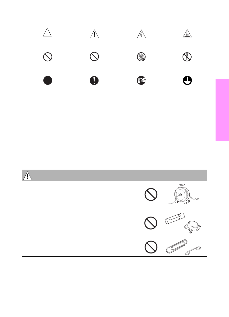
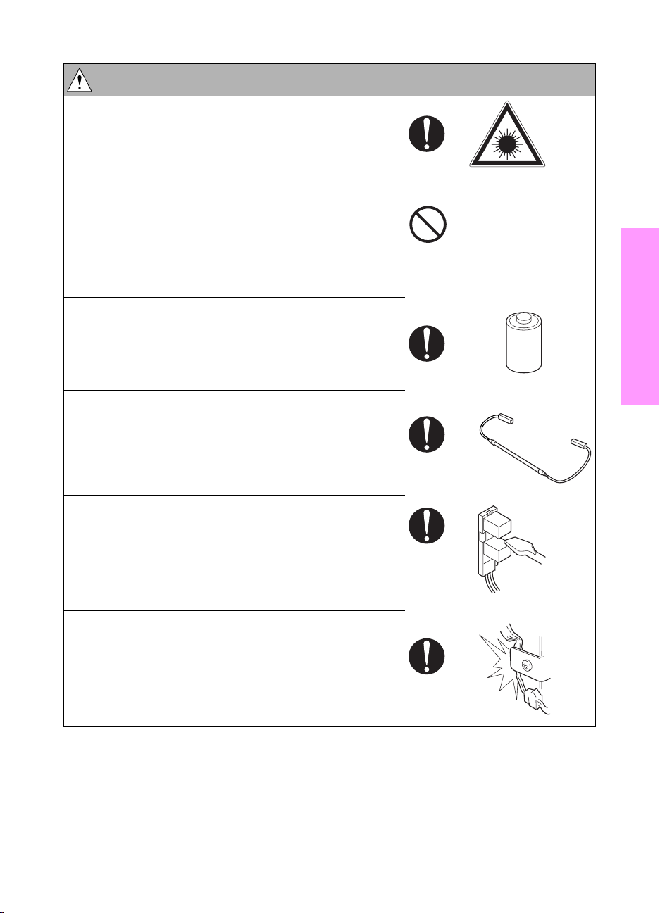
Symbols used for safety and important warning items are defined as follows:
Precaution when
using the MFP
Prohibition when
using the MFP
Direction when
using the MFP
General precaution Electric hazard High temperature
General prohibition Do not touch with wet hand Do not disassemble
General instruction Unplug Ground/Earth
Safety warnings
Modifications not authorized by hp
HP MFPs are renowned for their high reliability. This reliability is achieved through high-quality
design and a solid service network.
MFP design is a highly complicated and delicate process where numerous mechanical,
physical, and electrical aspects have to be taken into consideration, with the aim of arriving at
proper tolerances and safety factors. For this reason, unauthorized modifications involve a high
risk of degradation in performance and safety. Such modifications are therefore strictly
prohibited. the points listed below are not exhaustive, but they illustrate the reasoning behind
this policy.
WARNING: Prohibited actions
Safety
● Using any cables or power cord not specified by HP.
● Using any fuse or thermostat not specified by HP.
● Safety will not be assured, leading to a risk of fire
and injury.
● Disabling fuse functions or bridging fuse terminals
with wire, metal clips, solder or similar object.
ENWW Safety warnings 3
Page 12
WARNING: Prohibited actions
● Disabling relay functions (such as wedging paper
between relay contacts).
● Disabling safety functions (interlocks, safety circuits,
and so forth) Safety will not be assured, leading to a
risk of fire and injury.
● Making any modification to the MFP unless
instructed by HP.
● Using parts not specified by HP.
Checkpoints when performing on-site service
HP MFPs are extensively tested before shipping, to ensure that all applicable safety standards
are met, in order to protect the customer and customer engineer (hereafter called the CE) from
the risk of injury. However, in daily use, any electrical equipment may be subject to parts wear
and eventual failure. In order to maintain safety and reliability, the CE must perform regular
safety checks.
4Safety ENWW
Page 13
Power supply
WARNING: Wall outlet
● Check that mains voltage is as specified. Plug the
power cord into the dedicated wall outlet with a
capacity greater than the maximum power
consumption.
● If excessive current flows in the wall outlet, fire may
result.
● If two or more power cords can be plugged into the
wall outlet, the total load must not exceed the rating
of the wall outlet.
● If excessive current flows in the wall outlet, fire may
result.
kw
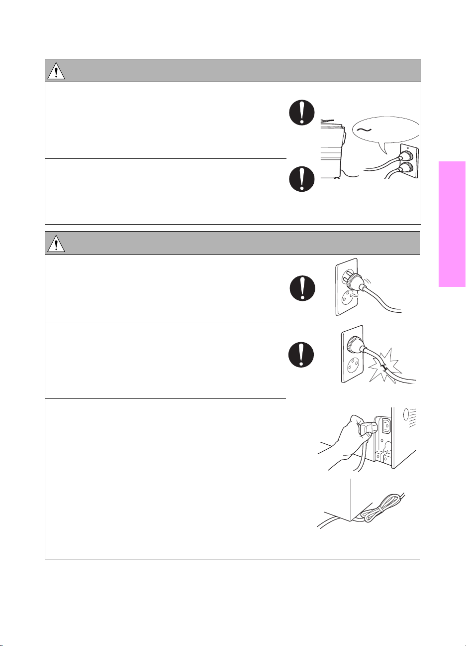
WARNING: Power plug and cord
● Make sure the power cord is plugged in the wall
outlet securely.
Contact problems may lead to increased resistance,
overheating, and the risk of fire.
● Check whether the power cord is damaged. Check
whether the sheath is damaged.
If the power plug, cord, or sheath is damaged,
replace with a new power cord (with plugs on both
ends) specified by HP. Using the damaged power
cord may result in fire or electric shock.
● When using the power cord (inlet type) that came
with this MFP, be sure to observe the following
precautions:
a Make sure the MFP-side power plug is securely
inserted in the socket on the rear panel of the
MFP.
Secure the cord with a fixture properly.
b If the power cord or sheath is damaged, replace
with a new power cord (with plugs on both ends)
specified by HP.
If the power cord (inlet type) is not connected to
the MFP securely, a contact problem may lead to
increased resistance, overheating, and risk of fire.
Safety
ENWW Safety warnings 5
Page 14
WARNING: Power plug and cord
Check whether the power cord is not stepped on or
●
pinched by a table and so on.
● Overheating may occur there, leading to a risk of
fire.
● Do not bundle or tie the power cord.
Overheating may occur there, leading to a risk of
fire.
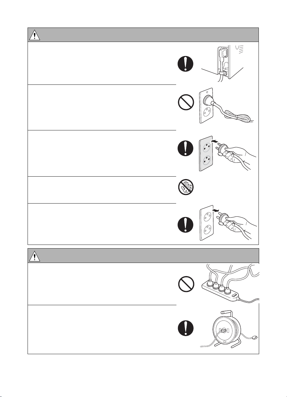
● Check whether dust is collected around the power
plug and wall outlet.
Using the power plug and wall outlet without
removing dust may result in fire.
● Do not insert the power plug into the wall outlet with
a wet hand.
The risk of electric shock exists.
● When unplugging the power cord, grasp the plug,
not the cable.
The cable may be broken, leading to a risk of fire
and electric shock.
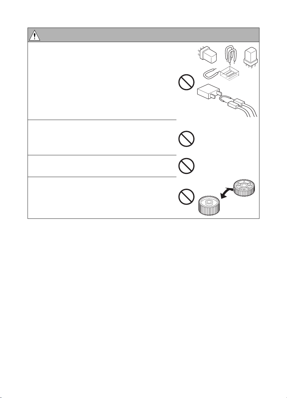
WARNING: Wiring
● Never use multi-plug adapters to plug multiple power
cords in the same outlet.
If used, the risk of fire exists.
● When an extension cord is required, use the
specified type.
Current that can flow in the extension cord is limited,
so using a too long extension cord may result in fire.
Do not use an extension cable reel with the cable
taken up. Fire may result.
6Safety ENWW
Page 15
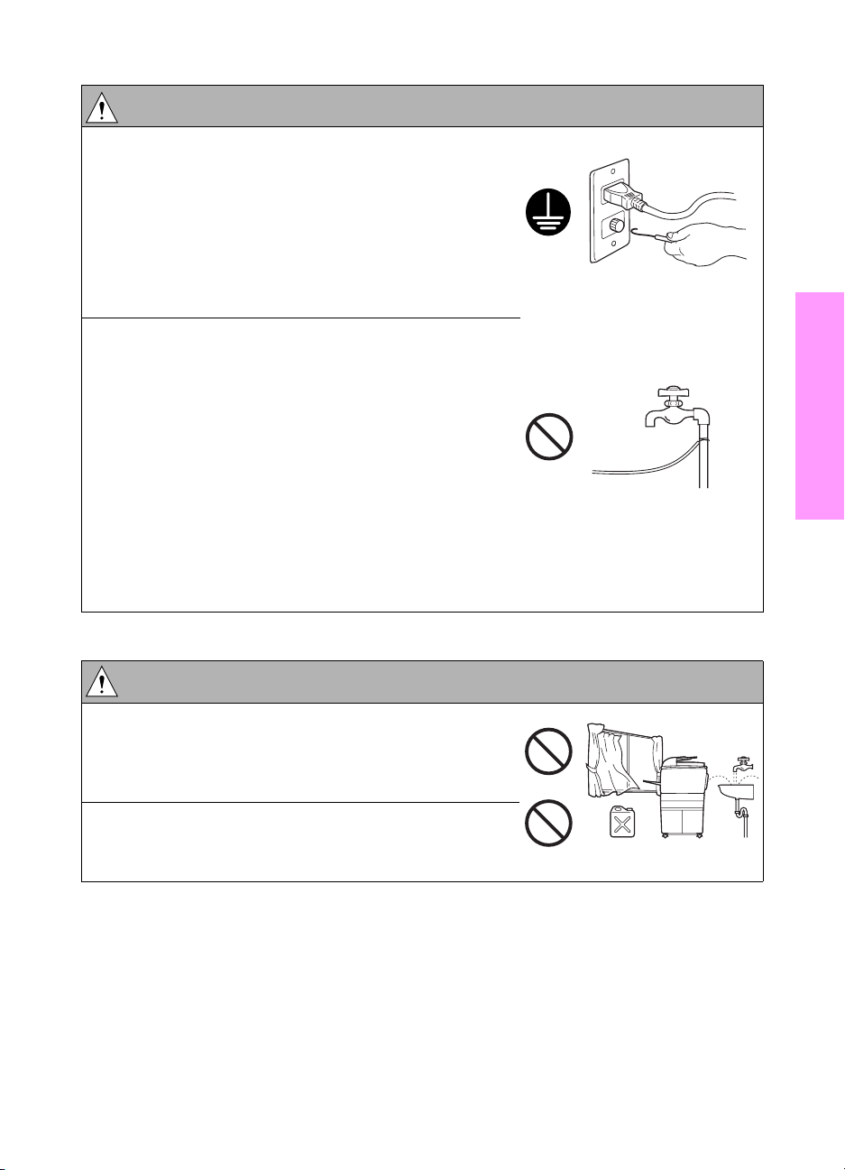
WARNING: Ground lead
● Check whether the MFP is grounded properly.
If current leakage occurs in an ungrounded MFP, you
may suffer electric shock while operating the MFP.
Connect the ground lead to one of the following
points:
a Ground terminal of wall outlet
b Ground terminal for which Class D work has been
done
● Pay attention to the point to which the ground lead is
connected.
Connecting the ground lead to an improper point
such as the points listed below results in a risk of
explosion and electric shock:
a Gas pipe (A risk of explosion or fire exists.)
b Lightning rod (A risk of electric shock or fire
exists.)
c Telephone line ground (A risk of electric shock or
fire exists in the case of lightning.)
d Water pipe or faucet (It may include a plastic
portion.)
Safety
Installation requirements
WARNING: Prohibited installation place
● Do not place the MFP near flammable materials
such as curtains or volatile materials that may catch
fire.
A risk of fire exists.
● Do not place the MFP in a place exposed to water
such as rain water.
A risk of fire and electric shock exists.
ENWW Safety warnings 7
Page 16
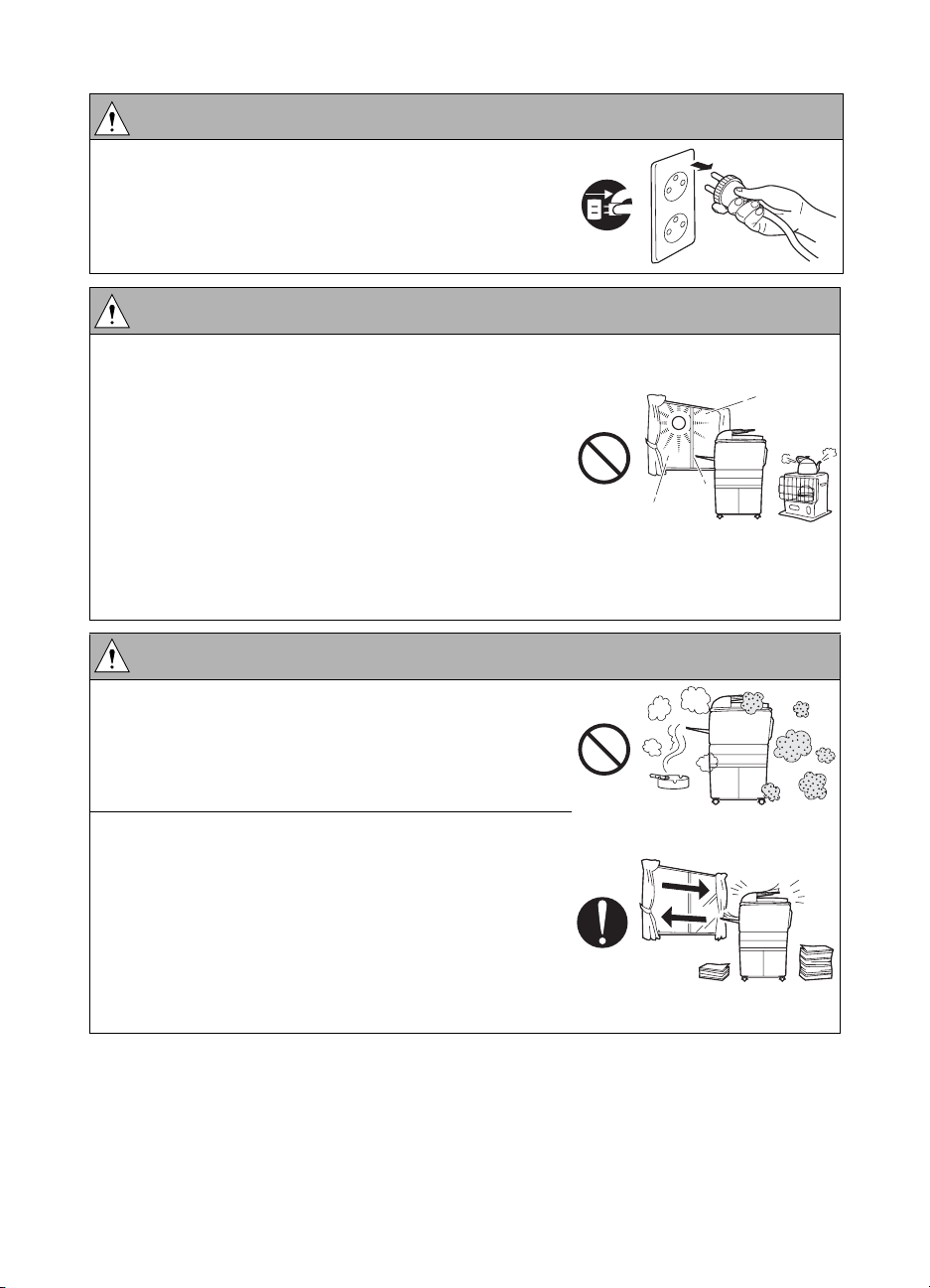
WARNING: Non-operational handling
● When the MFP is not used over an extended period
of time (holidays, and so forth), switch it off and
unplug the power cord.
Dust collected around the power plug and outlet may
cause fire.
CAUTION: Temperature and humidity
● Do not place the MFP in a place exposed to direct
sunlight or near a heat source such as a heater.
A risk of degradation in MFP performance or
deformation exists.
Do not place the MFP in a place exposed to cool
wind. Recommended temperature and humidity are
as follows:
Temperature: 10
Humidity: 10 percent to 80 percent (no dew
condensation)
Avoid other environments as much as possible.
° C to 30° C
CAUTION: Ventilation
● Do not place the MFP in a place where there is much
dust, cigarette smoke, or ammonia gas.
Place the MFP in a well ventilated place to prevent
MFP problems and image issues.
● The MFP generates ozone gas during operation, but
it is not sufficient to be harmful to the human body.
If a bad smell of ozone is present in the following
cases, ventilate the room.
a When the MFP is used in a poorly ventilated room
b When making a lot of copies
c When using multiple MFPs at the same time
8Safety ENWW
Page 17
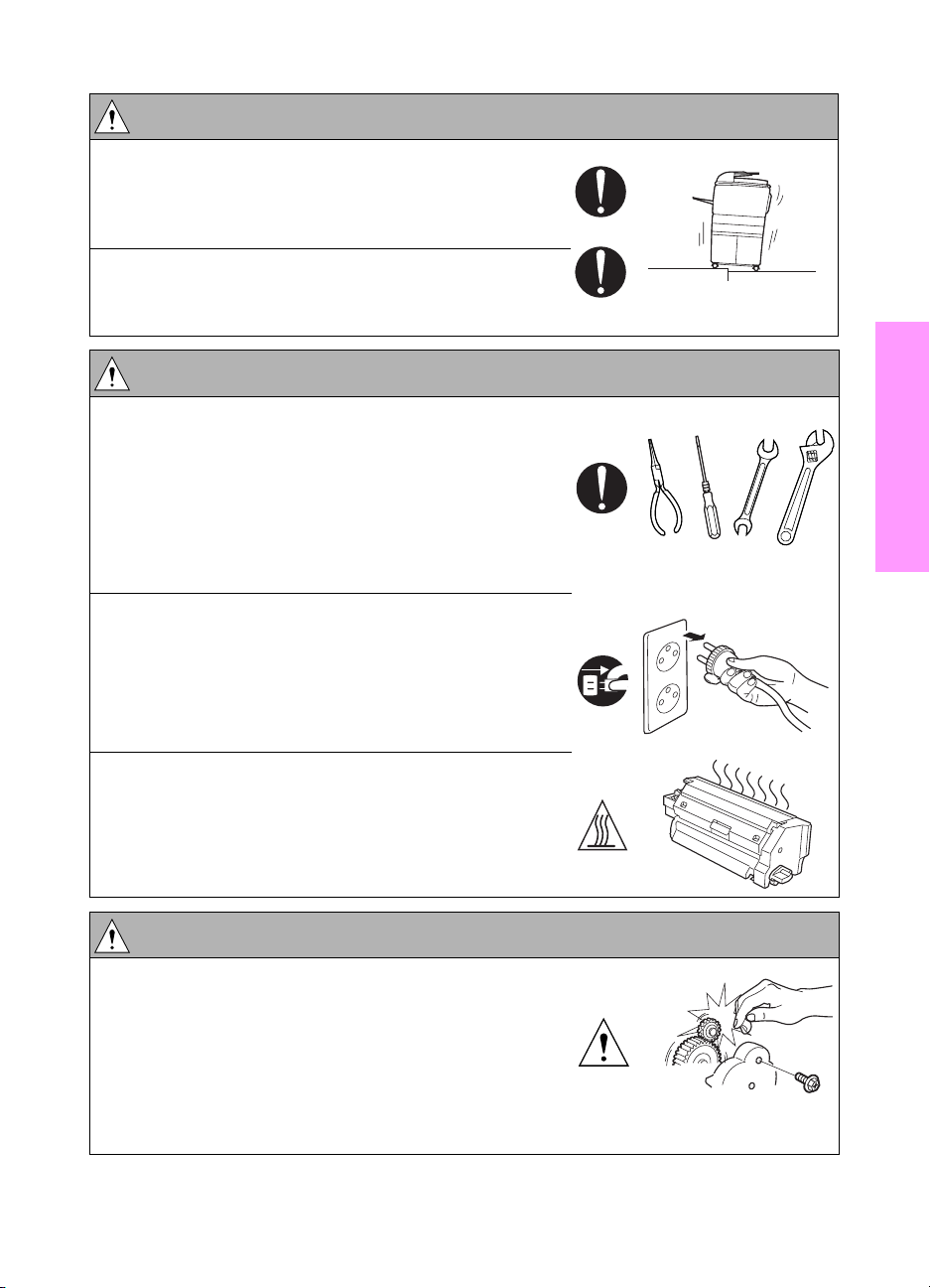
CAUTION: Vibration
● When installing the MFP, read the installation guide
thoroughly. Be sure to install the MFP on a level and
sturdy place.
Constant vibration will cause problems.
● Be sure to lock the caster stoppers.
In the case of an earthquake and so on, the MFP
may slide, leading to a injury.
CAUTION: Inspection before servicing
● Before conducting an inspection, read all relevant
documentation (service manual, technical notices,
and so forth) and proceed with the inspection
following the prescribed procedure in safety clothes,
using only the prescribed tools. Do not make any
adjustment not described in the documentation.
If the prescribed procedure or tool is not used, the
MFP may break and a risk of injury or fire exists.
● Before conducting an inspection, be sure to
disconnect the power plugs from the MFP and
options.
When the power plug is inserted into the wall outlet,
some units are still powered even if the power switch
is turned off. A risk of electric shock exists.
Safety
● The area around the fuser is hot.
You may get burned.
WARNING: Work performed with the MFP powered
● Take every care when making adjustments or
performing an operation check with the MFP
powered.
If you make adjustments or perform an operation
check with the external cover detached, you may
touch live or high-voltage parts or you may be caught
in moving gears or the timing belt, leading to a risk of
injury.
ENWW Safety warnings 9
Page 18
WARNING: Work performed with the MFP powered
Take every care when servicing with the external
●
cover detached.
High-voltage exists around the drum unit. A risk of
electric shock exists.
WARNING: Safety checkpoints
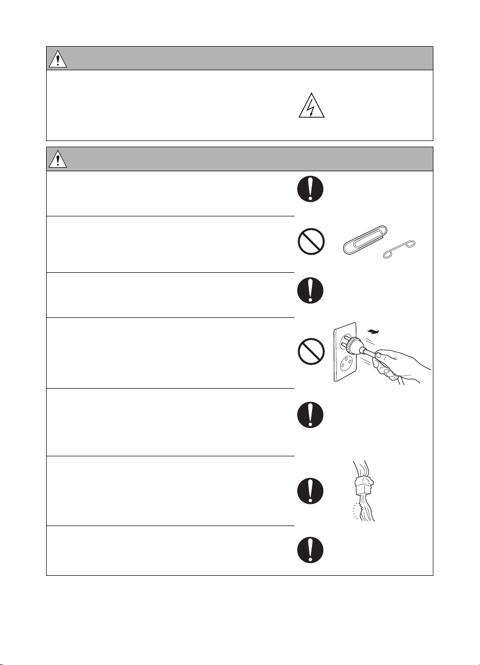
● Check the exterior and frame for edges, burrs, and
other damages.
The user or CE may be injured.
● Do not allow any metal parts such as clips, staples,
and screws to fall into the MFP.
They can short internal circuits and cause electric
shock or fire.
● Check wiring for squeezing and any other damage.
Current can leak, leading to a risk of electric shock
or fire.
● When disconnecting connectors, grasp the
connector, not the cable. (Specifically, connectors of
the AC line and high-voltage parts.)
Current can leak, leading to a risk of electric shock
or fire.
● Carefully remove all toner remnants and dust from
electrical parts and electrode units such as a
charging corona unit.
Current can leak, leading to a risk of MFP trouble or
fire.
● Check high-voltage cables and sheaths for any
damage.
Current can leak, leading to a risk of electric shock
or fire.
● Check electrode units such as a charging corona
unit for deterioration and sign of leakage.
Current can leak, leading to a risk of trouble or fire.
10 Safety ENWW
Page 19
WARNING: Safety checkpoints
● Before disassembling or adjusting the laser/scanner
assembly incorporating a laser, make sure that the
power cord has been disconnected.
The laser light can enter your eye, leading to a risk of
loss of eyesight.
● Do not remove the cover of the laser/scanner
assembly. Do not supply power with the
laser/scanner assembly shifted from the specified
mounting position.
The laser light can enter your eye, leading to a risk of
loss of eyesight.
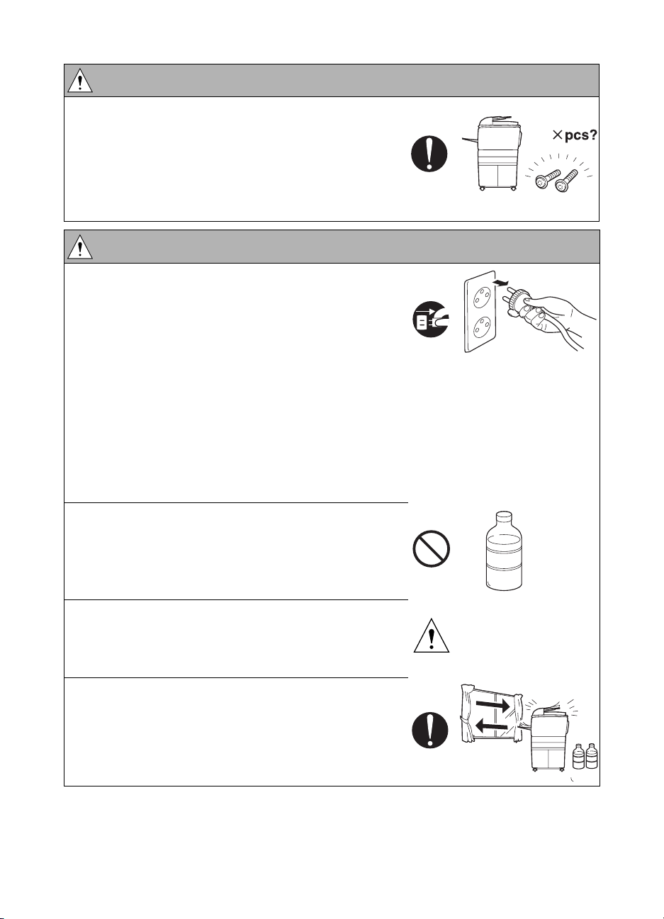
● When replacing a lithium battery, replace it with a
new lithium battery specified in the parts guide
manual. Dispose of the used lithium battery using
the method specified by local authority.
Improper replacement can cause explosion.
● After replacing a part to which AC voltage is applied
(for example, optical lamp and fuser lamp), be sure
to check the installation state.
A risk of fire exists.
Safety
● Check the interlock switch and actuator for loosening
and check whether the interlock functions properly.
If the interlock does not function, you may receive an
electric shock or be injured when you insert your
hand in the MFP (for example, for clearing paper
jam).
● Make sure the wiring cannot come into contact with
sharp edges, burrs, or other pointed parts.
Current can leak, leading to a risk of electric shock
or fire.
ENWW Safety warnings 11
Page 20
WARNING: Safety checkpoints
Make sure that all screws, components, wiring,
●
connectors, and so forth that were removed for
safety check and maintenance have been reinstalled
in the original location. (Pay special attention to
forgotten connectors, pinched cables, forgotten
screws, and so forth.)
A risk of MFP trouble, electric shock, and fire exists.
WARNING: Handling of service materials
● Unplug the power cord from the wall outlet.
● Drum cleaner (isopropyl alcohol) and roller cleaner
(acetone-based) are highly flammable and must be
handled with care. A risk of fire exists.
Use sparingly with wipes to avoid fumes.
Collect wipes in a resealable plastic bag, and
remove the bag from the customer’s site.
Have flammable spill absorbents in your tool box in
case material is spilled.
Consider using protective gloves if skin irritation
develops.
Containers should be labeled with the chemical
name and the word/symbol Flammable.
● Do not replace the cover or turn the MFP on before
any solvent remnants on the cleaned parts have fully
evaporated.
A risk of fire exists.
● Use only a small amount of cleaner at a time and
take care not to spill any liquid. If this happens,
immediately wipe it off.
A risk of fire exists.
● When using any solvent, ventilate the room well.
Breathing large quantities of organic solvents can
lead to discomfort.
12 Safety ENWW
Page 21
WARNING: Handling of service materials
● Toner and developer are not harmful substances, but
care must be taken not to breathe excessive
amounts or let the substances come into contact
with eyes, and so on. It may be stimulative.
If the substances get in the eye, rinse with plenty of
water immediately. When symptoms are noticeable,
consult a physician.
Avoid creating dust and inhaling dust, particularly
wen removing waste developer and adding new
developer.
Place waste toner and developer in a resealable
plastic bag, and remove the bag from the customer’s
site.
Use an explosion-proof vacuum with a HEPA filter for
cleaning up toner and developer.
● Never throw the used cartridge and toner into fire.
You may be burned due to dust explosion.
Measures to take in case of an accident
If an accident has occurred, the distributor who has been notified first must immediately take
emergency measures to provide relief to affected persons and to prevent further damage.
If a report of a serious accident has been received from a customer, an on-site evaluation must
be carried out quickly and HP Corporation must be notified.
To determine the cause of the accident, conditions and materials must be recorded through
direct on-site checks, in accordance with instructions issued by HP Corporation.
Safety
Conclusion
Safety of users and customer engineers depends highly on accurate maintenance and
administration. Therefore, safety can be maintained by the appropriate daily service work
conducted by the customer engineer.
When performing service, each MFP on the site must be tested for safety. The customer
engineer must verify the safety of parts and ensure appropriate management of the equipment.
ENWW Safety warnings 13
Page 22

Handling and disposition of consumables
All preventive maintenance replacement parts, consumables, and associated supplies,
including all wipes, waste developer, and so on, should be removed from the customer’s site.
Wipes, in particular wipes used with drum cleaner and roller cleaner, should be placed in a
resealable bag or other sealable container to avoid fumes and potential fire danger. Waste
developer should also be placed in a resealable bag or other sealable container to avoid
creating dust. Care should be taken when removing waste developer and when placing the
waste in the sealable container to avoid creating dust.
All parts, consumables, and associated supplies should be returned to the service office
location for appropriate recycling or disposal. Service office Environment, Health, and Safety
staff should be consulted to determine the proper handling and disposition.
Regulatory statements
FCC Regulations
FCC Class A Statement
This equipment has been tested and found to comply with the limits for a Class A digital device,
pursuant to Part 15 of the FCC Rules. These limits are designed to provide reasonable
protection against harmful interference when the equipment is operated in a commercial
environment. This equipment generates, uses, and can radiate radio frequency energy and, if
not installed and used in accordance with the instruction manual, may cause harmful
interference to radio communications. Operation of this equipment in a residential area is likely
to cause harmful interference, in which case the user will be required to correct the interference
at his own expense. The end user of this product should be aware that any changes or
modifications made to this equipment without the approval of Hewlett-Packard could result in
the product not meeting the Class A limits, in which case the FCC could void the user’s authority
to operate the equipment.
● Reorient or relocate the receiving antenna.
● Increase separation between equipment and receiver.
● Connect equipment to an outlet on a circuit different from that to which the receiver is
located.
● Consult your dealer or an experienced radio/TV technician.
Note Any changes or modifications to the MFP that are not expressly approved by HP
14 Safety ENWW
could void the user’s authority to operate this equipment.
Use of a shielded interface cable is required to comply with the Class A limits of
Part 15 of FCC rules.
Page 23
Safety information
Safety circuits
This MFP is provided with the following safety circuits to prevent MFP issues from resulting in
serious accidents.
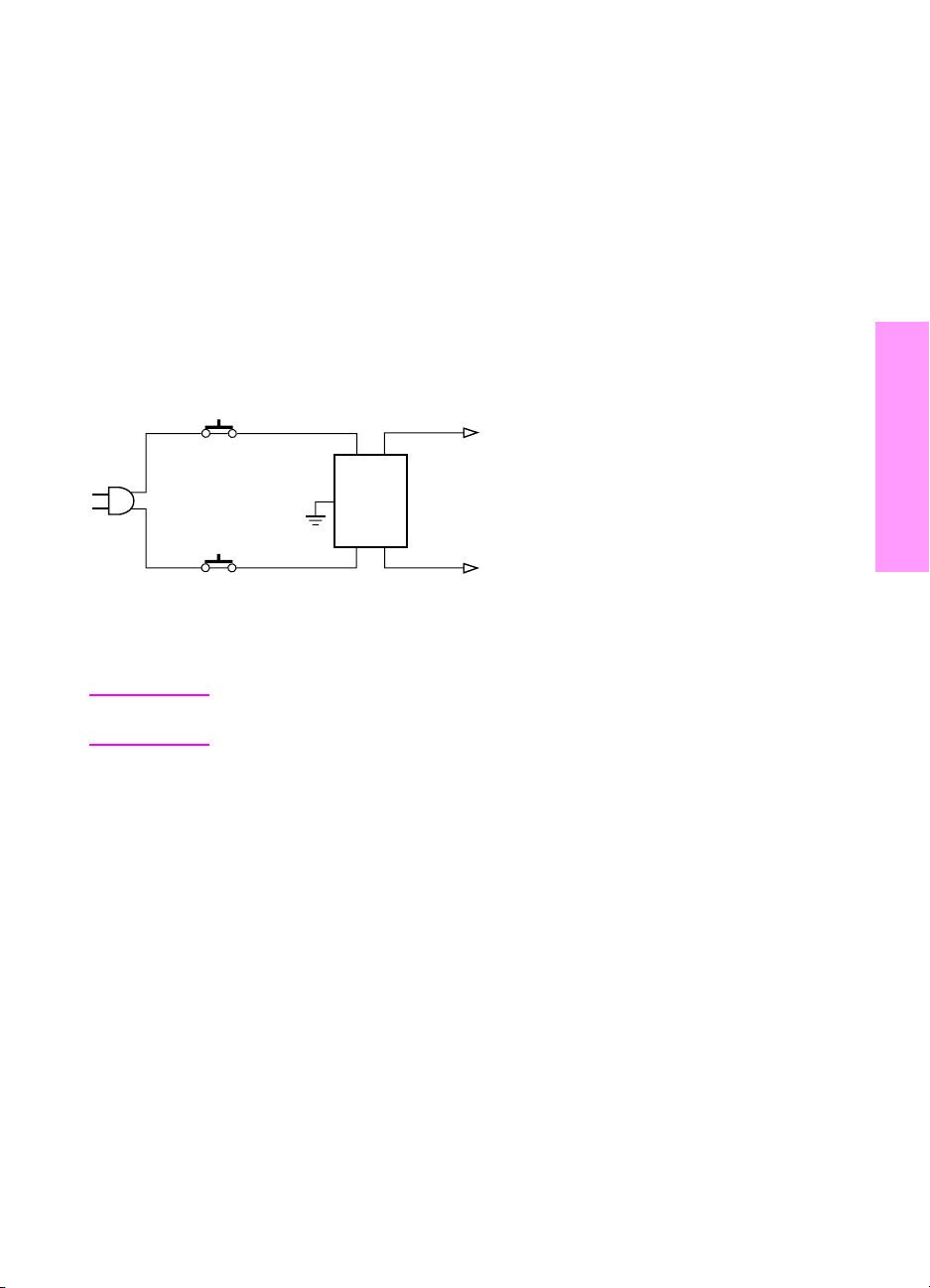
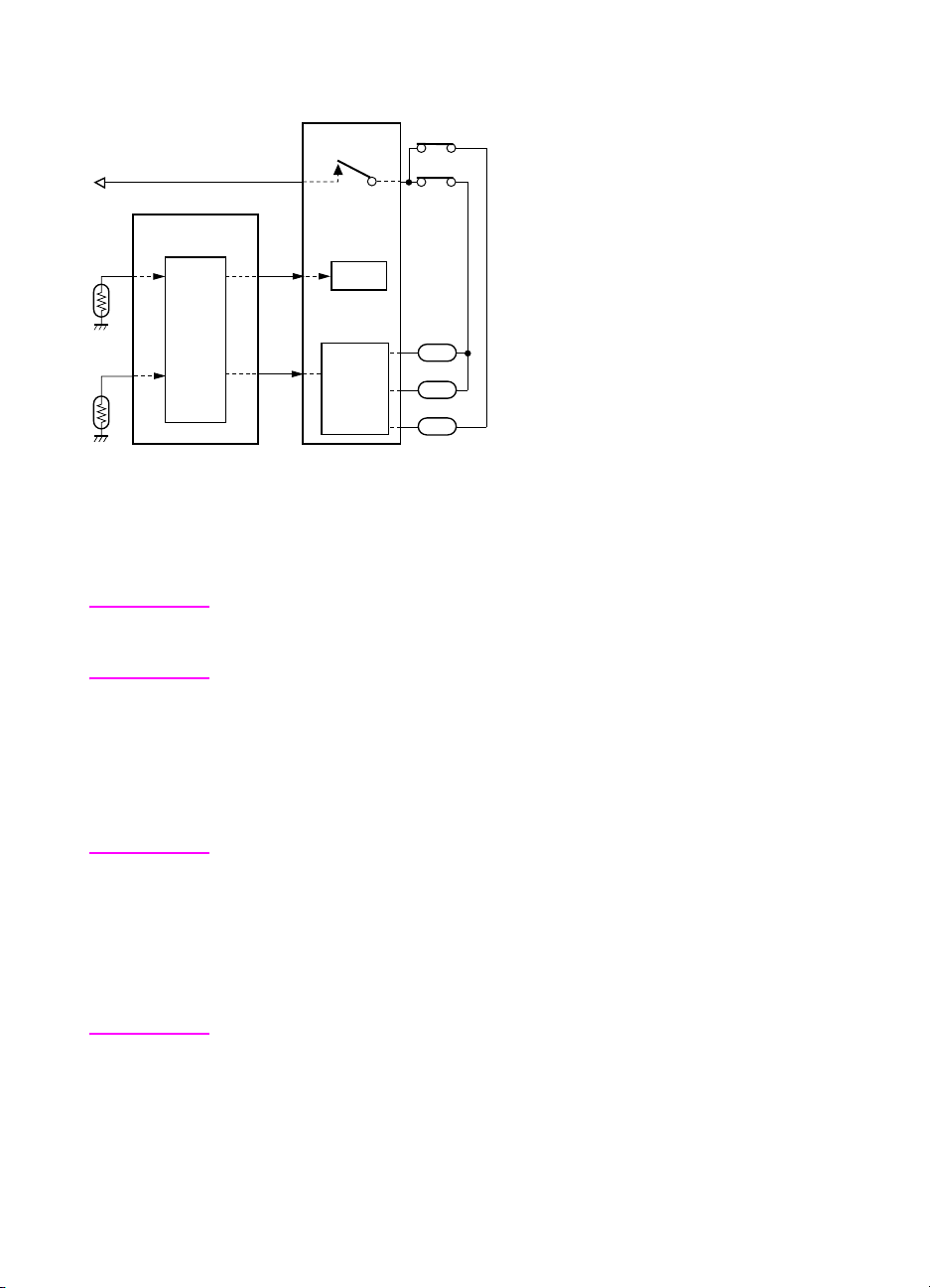
Overall protection circuit
L2 and L3 (fuser heater lamps) overheating prevention circuit
These safety circuits are described below to provide the service engineer with a renewed
awareness of them in order to prevent servicing errors that may impair their functions.
Overall protection circuit
CBR1
NF
CBR2
Protection by CBR1 and CBR2 (circuit breakers)
CBR1 and CBR2 interrupt the AC line instantaneously when an excessive current flows due to a
short in the AC line.
Safety
CAUTION The CBR1 and CBR2 functions must not be deactivated under any
circumstances.
ENWW Safety information 15
Page 24
Protection by L2, L3, and L4 (fuser heater lamps) overheating prevention circuit
TS2
TS1
L2
L3
L4
TH2
TH1
DCPS
RL1
PRCB
RL1
Control
section
AC driver
section
Protection by software
The output voltage from TH1 (fuser temperature sensor 1) is read by the CPU. If this voltage is
abnormal, L2 (fuser heater lamp 1), L3 (fuser heater lamp 2), L4 (fuser heater lamp 3), and RL1
(main relay) are turned off.
CAUTION Do not change the gap between the roller and TH1. When replacing TH1, check
the specified mounting dimensions. The RL1 function must not be deactivated
under any circumstances.
Protection by the hardware circuit
The output voltages from TH1 and TH2 (fuser temperature sensors) are compared with the
abnormality judgment reference value in the comparator circuit. If the output voltage from TH1
or TH2 exceeds the reference value, L2 (fuser heater lamp 1), L3 (fuser heater lamp 2), L4
(fuser heater lamp 3), and RL1 (main relay) are turned off in hardware means.
CAUTION Periodically check the TH2 face contacting the roller, and replace TH2 if any
abnormality is detected.
Since theTH1 (fuser temperature sensor) face does not contact the roller, check
the distance from the roller and the sensor orientation if any abnormality is
detected.
The RL1 function must not be deactivated under any circumstances.
16 Safety ENWW
Page 25

Protection by TS1 (thermostat/U) and TS2 (thermostat/L)
When the temperature of the fuser roller (upper/lower) exceeds the specified value, TSs are
turned off, thus interrupting the power to L2 (fuser heater lamp/1), L3 (fuser heater lamp/2), and
L4 (fuser heater lamp/3) directly.
CAUTION Do not use any other electrical conductor in place of TS1 and TS2. Do not
change the distance between the roller and TS (thermostat).
Safety
ENWW Safety information 17
Page 26
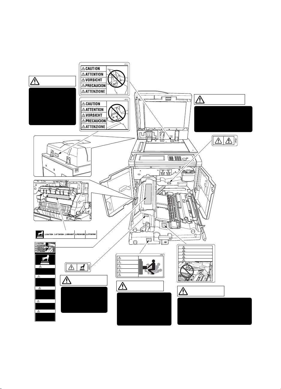
Safety labels on the MFPs
Caution labels shown below are attached in some areas on/in the MFP. When accessing these
areas for maintenance, repair, or adjustment, special care should be taken to avoid burns and
electric shock.
CAUTION
DO NOT INSERT
your finger into the
two RADF hinge
portions;
otherwise you may
be injured.
WARNING
This area generates
high voltage. If touched,
electrical shock may
occur. DO NOT TOUCH.
CAUTION
ATTENTION
VORSICHT
PRECAUCION
ATTENZIONE
CAUTION
DO NOT put your hand between
the main body and developing
fixing unit; otherwise you may
be injured.
CAUTION
High temperature!
Do not touch. Use care
when clearing paper.
ATTENTION
Temp rature lev e!
Risque de br lure. Soyez
prudent en retirant la
feuille coinc e.
VORSICHT
Hei§e OberflŠche!
Brandverletzungsgefahr.
Bei Beseitigung von
Papierstaus vorsichtig
vorgehen.
PRECAUCION
ÁTemperatura alta!
No tocar. Tener cuidado al
remover el papel.
ATTENZIONE
Alta temperatura!
Non toccare. Agire con
prudenza nel rimuovere la
carta.
CAUTION
The fixing unit is
very hot. To avoide
getting burned, DO
NOT TOUCH.
CAUTION
ATTENTION
VORSICHT
PRECAUCION
ATTENZIONE
CAUTION
The conveyance fixing
unit is heavy. Use care
and draw it out gently;
otherwise you may be
injured.
18 Safety ENWW
Page 27
Safety
CAUTION You may be burned or injured if you touch any area that you are advised by
any caution label to avoid.
ENWW Safety labels on the MFPs 19
Page 28
CAUTION Do not remove caution labels. If any caution label has come off or is soiled and
therefore the caution cannot be read, contact our Service Office.
Scanner section
Laser/scanner assembly
Rear cover
CAUTION You may be burned or injured if you touch any area that you are advised by
any caution label to avoid.
20 Safety ENWW
Page 29

2Adjustments
How to use this section . . . . . . . . . . . . . . . . . . . . . . . . . . . . . . . . . . . . . . . . . 24
Scope and precautions . . . . . . . . . . . . . . . . . . . . . . . . . . . . . . . . . . . . . 24
Adjustments made when replacing parts . . . . . . . . . . . . . . . . . . . . . . . . . . . . 24
How to read tables . . . . . . . . . . . . . . . . . . . . . . . . . . . . . . . . . . . . . . . . . 25
List of adjustment items on 9055mfp/9065mfp . . . . . . . . . . . . . . . . . . . . . . . 26
LCD adjustment . . . . . . . . . . . . . . . . . . . . . . . . . . . . . . . . . . . . . . . . . . . . . . . 28
LCD control panel adjustment . . . . . . . . . . . . . . . . . . . . . . . . . . . . . . . . 28
LCD panel contrast/key sound adjustment . . . . . . . . . . . . . . . . . . . . . . 28
Settings and adjustments made with the P function . . . . . . . . . . . . . . . . . . . 28
Checking and printing the P function . . . . . . . . . . . . . . . . . . . . . . . . . . . 28
Setting up the P function . . . . . . . . . . . . . . . . . . . . . . . . . . . . . . . . . . . . 28
Mode changing menu. . . . . . . . . . . . . . . . . . . . . . . . . . . . . . . . . . . . . . . . . . . 29
Mode selection. . . . . . . . . . . . . . . . . . . . . . . . . . . . . . . . . . . . . . . . . . . . 29
2-5 mode . . . . . . . . . . . . . . . . . . . . . . . . . . . . . . . . . . . . . . . . . . . . . . . . . . . . 29
Setting the 2-5 mode . . . . . . . . . . . . . . . . . . . . . . . . . . . . . . . . . . . . . . . 29
List of adjustment items for 2-5 mode . . . . . . . . . . . . . . . . . . . . . . . . . . 30
Setting software switches. . . . . . . . . . . . . . . . . . . . . . . . . . . . . . . . . . . . 31
List of software switches . . . . . . . . . . . . . . . . . . . . . . . . . . . . . . . . . . . . 32
PM count resetting . . . . . . . . . . . . . . . . . . . . . . . . . . . . . . . . . . . . . . . . . 45
Setting the PM cycle . . . . . . . . . . . . . . . . . . . . . . . . . . . . . . . . . . . . . . . 45
Collecting data . . . . . . . . . . . . . . . . . . . . . . . . . . . . . . . . . . . . . . . . . . . . 46
Copy count by parts to be replaced (fixed parts) . . . . . . . . . . . . . . . . . . 57
Copy count parts counter. . . . . . . . . . . . . . . . . . . . . . . . . . . . . . . . . . . . 58
Copy count by parts to be replaced (optional parts) . . . . . . . . . . . . . . . 61
Setting passwords . . . . . . . . . . . . . . . . . . . . . . . . . . . . . . . . . . . . . . . . . 62
Setting the telephone number and/or fax number of the
service center. . . . . . . . . . . . . . . . . . . . . . . . . . . . . . . . . . . . . . . . . 63
Setting the serial number . . . . . . . . . . . . . . . . . . . . . . . . . . . . . . . . . . . . 63
Setting date . . . . . . . . . . . . . . . . . . . . . . . . . . . . . . . . . . . . . . . . . . . . . . . . . . 64
3-6 mode . . . . . . . . . . . . . . . . . . . . . . . . . . . . . . . . . . . . . . . . . . . . . . . . . . . . 64
Setting method. . . . . . . . . . . . . . . . . . . . . . . . . . . . . . . . . . . . . . . . . . . . 64
List of adjustment items for 3-6 mode . . . . . . . . . . . . . . . . . . . . . . . . . . 65
High voltage adjustment. . . . . . . . . . . . . . . . . . . . . . . . . . . . . . . . . . . . . 67
Charging grid voltage adjustment . . . . . . . . . . . . . . . . . . . . . . . . . . . . . 68
Drum calibration adjustment . . . . . . . . . . . . . . . . . . . . . . . . . . . . . . . . . 68
Drum calibration adjustment (manual) . . . . . . . . . . . . . . . . . . . . . . . . . . 73
Custom paper setting. . . . . . . . . . . . . . . . . . . . . . . . . . . . . . . . . . . . . . . 73
Recall standard data (process adjustment) . . . . . . . . . . . . . . . . . . . . . . 73
Image adjustment. . . . . . . . . . . . . . . . . . . . . . . . . . . . . . . . . . . . . . . . . . 73
Tray adjustment . . . . . . . . . . . . . . . . . . . . . . . . . . . . . . . . . . . . . . . . . . . 73
Adjustments
ENWW 21
Page 30

Magnification adjustment . . . . . . . . . . . . . . . . . . . . . . . . . . . . . . . . . . . . 74
Document feeder adjustment . . . . . . . . . . . . . . . . . . . . . . . . . . . . . . . . . 80
Distortion adjustment (MFP) . . . . . . . . . . . . . . . . . . . . . . . . . . . . . . . . . 83
Non-image area erase check . . . . . . . . . . . . . . . . . . . . . . . . . . . . . . . . . 83
Recall standard data (Image adjustment) . . . . . . . . . . . . . . . . . . . . . . . 84
Running test mode. . . . . . . . . . . . . . . . . . . . . . . . . . . . . . . . . . . . . . . . . 84
Test pattern density setting . . . . . . . . . . . . . . . . . . . . . . . . . . . . . . . . . . 92
Finisher adjustment . . . . . . . . . . . . . . . . . . . . . . . . . . . . . . . . . . . . . . . . 92
Stapling and folding stopper adjustment . . . . . . . . . . . . . . . . . . . . . . . . 92
List output mode. . . . . . . . . . . . . . . . . . . . . . . . . . . . . . . . . . . . . . . . . . . 96
4-7 Mode . . . . . . . . . . . . . . . . . . . . . . . . . . . . . . . . . . . . . . . . . . . . . . . . . . . . 96
4-7 Mode/multi-mode setting method. . . . . . . . . . . . . . . . . . . . . . . . . . . 96
Adjustment data display . . . . . . . . . . . . . . . . . . . . . . . . . . . . . . . . . . . . . 98
Hard disk check . . . . . . . . . . . . . . . . . . . . . . . . . . . . . . . . . . . . . . . . . . . 98
Input checklist . . . . . . . . . . . . . . . . . . . . . . . . . . . . . . . . . . . . . . . . . . . . . . . . .100
Output checklist . . . . . . . . . . . . . . . . . . . . . . . . . . . . . . . . . . . . . . . . . . 104
Other adjustments . . . . . . . . . . . . . . . . . . . . . . . . . . . . . . . . . . . . . . . . . . . . 111
Tray centering adjustment . . . . . . . . . . . . . . . . . . . . . . . . . . . . . . . . . . 111
HCI: Paper size adjustment . . . . . . . . . . . . . . . . . . . . . . . . . . . . . . . . . 113
MFP skew adjustment . . . . . . . . . . . . . . . . . . . . . . . . . . . . . . . . . . . . . 114
HCI pick roller pressure adjustment (ledger/A3 only). . . . . . . . . . . . . . 114
HCI lift plate horizontal adjustment . . . . . . . . . . . . . . . . . . . . . . . . . . . 115
HCI skew adjustment . . . . . . . . . . . . . . . . . . . . . . . . . . . . . . . . . . . . . . 117
Trays 1-4, HCI, and PI spring pressure adjustment . . . . . . . . . . . . . . . 118
HCI paper feed height upper limit adjustment . . . . . . . . . . . . . . . . . . . 120
HCI pick-up release amount adjustment . . . . . . . . . . . . . . . . . . . . . . . 121
ADF: aligning on top of scanner. . . . . . . . . . . . . . . . . . . . . . . . . . . . . . 122
ADF: alignment to ADF glass. . . . . . . . . . . . . . . . . . . . . . . . . . . . . . . . 123
ADF: paper skew adjustment . . . . . . . . . . . . . . . . . . . . . . . . . . . . . . . . 124
Finisher: adjusting the magnets on the bypass conveyance
guide plate . . . . . . . . . . . . . . . . . . . . . . . . . . . . . . . . . . . . . . . . . . 125
Finisher: adjusting the bypass gate . . . . . . . . . . . . . . . . . . . . . . . . . . . 126
Finisher: adjusting the shift position. . . . . . . . . . . . . . . . . . . . . . . . . . . 128
Finisher: adjusting the paper exit solenoid. . . . . . . . . . . . . . . . . . . . . . 129
Finisher: adjusting the mount location of the paper exit arm . . . . . . . . 130
Finisher: adjusting the mount location of the alignment plates/U . . . . . 131
Finisher: adjusting the mount location of the alignment plates/L
(Multifunction Finisher only) . . . . . . . . . . . . . . . . . . . . . . . . . . . . . 132
Finisher: adjusting the stapling position (flat stapling) . . . . . . . . . . . . . 133
Finisher: adjusting the stapler vertical positioning . . . . . . . . . . . . . . . . 134
Finisher: adjusting the stapling position (staple-and-fold)
(Multifunction Finisher only) . . . . . . . . . . . . . . . . . . . . . . . . . . . . . 136
Finisher: adjusting the angle of the folding stopper (Multifunction
Finisher only) . . . . . . . . . . . . . . . . . . . . . . . . . . . . . . . . . . . . . . . . 137
Finisher: adjusting the folding force (Multifunction Finisher only) . . . . 138
Finisher: adjusting the tri-fold positions (Multifunction Finisher only). . 139
Adjusting the vertical skew of the punch kit . . . . . . . . . . . . . . . . . . . . . 140
Sensor threshold adjustment for the punch kit paper edge sensor . . . 141
PI centering adjustment . . . . . . . . . . . . . . . . . . . . . . . . . . . . . . . . . . . . 142
Adjusting the vertical skew when using the post inserter. . . . . . . . . . . 144
Finisher: stapler driver belt position adjustment . . . . . . . . . . . . . . . . . . 145
22 ENWW
Page 31

Other adjustments . . . . . . . . . . . . . . . . . . . . . . . . . . . . . . . . . . . . . . . . . . . . 146
MFP: Optics unit alignment . . . . . . . . . . . . . . . . . . . . . . . . . . . . . . . . . 146
MFP: Scanner motor belt adjustment. . . . . . . . . . . . . . . . . . . . . . . . . . 146
MFP: Fuser temp sensor alignment. . . . . . . . . . . . . . . . . . . . . . . . . . . 146
MFP: Fuser thermostat alignment . . . . . . . . . . . . . . . . . . . . . . . . . . . . 146
Finisher: Up/down wire tension adjustment . . . . . . . . . . . . . . . . . . . . . 146
ENWW 23
Adjustments
Page 32

How to use this section
Note Disregard any references
in this manual to the
following:
• KRDS
• PZ
• PK-110
They are not used with the
HP LaserJet 9055mfp and
HP LaserJet 9065mfp.
Scope and precautions
This section provides detailed information
about adjustment items and procedures.
Before addressing customer complaints,
perform the following checks.
1 Check whether the power supply voltage
meets the specifications.
2 Check whether the power supply is
properly grounded.
3 Check whether this MFP shares the power
supply with any other MFP that draws
large current intermittently (for example,
elevator and air conditioners that produce
electrical noise).
4 Check whether the installation
environment is good.
a High temperature/high humidity, direct
sunlight, ventilation, and so forth.
b Level of installed location
5 Check whether original has a problem that
may cause defective images.
6 Check whether the selected density value
is correct.
7 Check whether the scanner glass, ADF
glass, and so forth is soiled.
8 Check whether correct paper is used for
copying.
9 Check whether copying materials and
parts (for example, developer, drum, and
cleaning blade) are replenished and
replaced when they reach the end of their
useful life.
10 Check whether toner remains.
When servicing the MFP, observe the
following precautions:
a Only either side of the AC line is shut off
when the primary power switch (SW1)
of this MFP is turned off. Always unplug
the power cord before starting service
work. If it is necessary to service the
MFP with the power on, take care not to
be caught in the scanning gear of the
exposure unit.
b Special care should be taken when
handling the fuser because it operates
at extremely high temperatures.
c The developing unit has a strong
magnetic field. Keep watches and
measuring equipment away from it.
d Take care not to damage the drum with
tools and so on.
e Do not touch IC pins with bare hands.
Adjustments made when replacing parts
Adjustments (including checks) and settings
are not only required when a customer
complaint about the copy image quality is
received but also after replacing or
reassembling parts.
24 Adjustments ENWW
Page 33

How to read tables
Components of the tables used in this
section are as follows:
1 Mode
Adjustment mode to be selected.
[P]: P mode [25]: 2-5 mode
[36]: 3-6 mode [47]: 4-7 mode
[?]: key operator mode
2 Code
Code and copy quantity setting button
used in each mode.
3 Page
Page in the “Adjustment” section.
4 Circled numbers
1 2
Indicate that adjustments
(including checks) must be made in order
of precedence.
(Circle without numeric character):
Indicates that adjustments (including
checks) can be made independently.
ENWW Adjustments made when replacing parts 25
Adjustments
Page 34

List of adjustment items on 9055mfp/9065mfp
Item No.
Classification by Adjustment
1 Process
adjustment
2Drum
3 Auto maximum contrast
4 Auto dot diameter
5 LD1 offset adjustment 1-51
6 LD2 offset adjustment 1-52
7 Auto gamma adjustment
8 Auto gamma adjustment
9 Cartridge set mode (drum) 1-54
10 Image
adjustment
11 Magnification
12 MFP horizontal
13 Scanner drum clock
14 ADF drum clock adjustment 1-59 O O
15 Timing
16 MFP registration loop
17 MFP pre-registration
18 MFP leading edge timing
19 Scanner restart timing
20 ADF restart timing
21 Scanner (ADF) registration
22 Document
23 ADF original size
24 ADF skew offset adjustment 1-66 O O
25 Centering
26 Scanner (platen) centering
27 ADF centering adjustment 1-68 O O O
28 Warp
29 Scanner (platen) warp
30 Scanner (ADF) warp (main
31 Scanner (ADF) warp
32 Finisher
adjustment
33 Folding stopper adjustment 1-79 O O
34 Cover sheet tray size adjustment 1-80 O O
35 Finisher
adjustment
36 Punch horizontal
37 Punch registration loop
High voltage
adjustment
calibration
adjustment
Tray adjustment
adjustment
adjustment
feeder
adjustment
adjustment
adjustment
(MFP)
Stapling and folding stopper adjustment 1-79 O O
Punch
adjustment
Adjustment Item
Charging grid manual
adjustment
Blade setting mode 1-49
adjustment
adjustment
Mode
36 1-48
1-49
1-50
Page
Drum
Developer
Laser/scanner assembly
c
e
fdcc
gedd
Dust-proof glass
Each tray unit
Tray 1 paper feed unit
Tray up/down wire
Registration roller
Registration unit
Registration clutch
Mis-centering detection sensor
ADU unit
CCD unit
Fuser
hfe
igf
1-53
(1dot)
(2dot)
1-54
jhge
kihf
dc
1-56 O O O
MFP vertical magnification
adjustment
magnification adjustment
adjustment
MFP leading edge timing
adjustment
adjustment
adjustment
adjustment
adjustment
adjustment
loop adjustment
Document feeder contrast
adjustment
adjustment
MFP centering adjustment 1-67 O O O
adjustment
Scanner (platen) warp (main
scan)
(secondary)
scan)
(secondary)
Punch vertical position
adjustment
position adjustment
adjustment
1-57 O O O
1-58 O O O
1-58 O O
1-61 O O O O O
1-61 O
1-62 O
1-62 O
1-63 O O
1-63 O O O
1-64 O
1-65 O
1-65 O O
1-67 O O
1-68 O O
1-68 O O
1-68 O O
1-68 O O
36 1-81 O O
1-81 O O
1-81-1 O O
Memory board
ADF
HCI
Finisher
O
O
O
O
O
O
O
O
O
Stapler unitPIPK (Punch kits)
26 Adjustments ENWW
Page 35

Item No.
Classification by Adjustment
40 Tri-folding stopper adjustment 1-82 O O
41 2 Positions staple pitch adjustment 1-82 O O
42 Tray centering adjustment 1-97 O O
43 ADF mounting position adjustment 1-108 O
44 ADF s kew adjustment 1-109 O
45 ADF p aper skew
adjustment
46 Back side of original paper 1-111 O
47 PI centering adjustment 1-129
48 PK adjusting the skew of punched holes position 1-127
49 PK adjusting the vertical positioning of punched holes 1-128
50 Drum count reset 1-38 O
51 Developer count reset 25 1-38 O
52 Web counter reset 1-38 O
Adjustment Item
Face side of original paper 1-110 O
Mode
Other Adjustments
Page
Drum
Developer
Laser/scanner assembly
Dust-proof glass
Each tray unit
Tray 1 paper feed unit
Tray up/down wire
Registration roller
Registration unit
Registration clutch
Mis-centering detection sensor
ADU unit
CCD unit
Fuser
Memory board
ADF
CAUTION When replacing the Image
Control Board (ICB), the
memory board located on
the ICB must be installed
on the replacement ICB.
The memory board
contains the adjustment
values for the MFP.
If the memory board
requires replacement,
contact HP technical
support for instructions.
HCI
Finisher
Stapler unitPIPK (Punch kits)
Adjustments
ENWW List of adjustment items on 9055mfp/9065mfp 27
Page 36

LCD adjustment
LCD control panel adjustment
Enter the key operator mode and touch
10
Touch panel adjustment to adjust
the LCD touch panel.
* If you cannot select the touch panel
adjustment mode, follow this procedure:
1 Power on the MFP secondary power
switch while holding down the Help
button. This will take you directly to key
operator mode.
2 Touch any key on the numeric key pad to
access Touch panel adjustment.
10
LCD panel contrast/key sound adjustment
Enter the key operation mode and touch
7
LCD Panel contrast/Key sound
adjustment to adjust the contrast,
backlight, and/or buzzer as desired.
Settings and adjustments made with the P function
The P function allows you to perform
following numerical value checks using the
P button:
1 Total counter
2 Copy controller counter
3 MFP counter
4 PM counter *
5 Density shift (auto <text/photo>)
6 Density shift (increase contrast)
7 Density shift (photo)
8 Density shift (text)
Checking and printing the
P function
1 Turn on the secondary power switch
(SW2).
2 Press the P button.
3 Counter list is displayed.
4 Touch the key.
5 Press the START button to print out the
counter list. The P function is cancelled
automatically.
6 If the counter list need not be displayed,
touch the key.
COUNTER MENU
EXIT
Setting up the P function
1 Turn on the secondary power switch
(SW2).
2 Touch the key.
3 Select the required image quality, text,
photo, and so forth. Then press the P
button to set the desired density shift.
4 Enter a value (0-5) with a numeric key,
then touch the key. The smaller the
value, the darker the density.
5 Touch the key to return to the main
screen.
SPECIAL
ORIGINAL
OK
OK
28 Adjustments ENWW
Page 37

Mode changing menu
Mode selection
You can select a mode from the following
Mode changing menu: Select mode without
turning off and on the power switch.
1
Main screen
2
3-6 mode
3
2-5 mode
4
Key operation mode
5
4-7 mode
Step Operation
1 Turn on the secondary power switch (SW2).
2 Press P button and wait until Enter password
for mode selection message appears.
3 Enter the password 9272 and press the START
button. (Note that this password is fixed and
cannot be changed.)The Mode changing menu
appears.
4 Enter the number to select the desired mode.
5 To return to the Mode Changing menu, press the
P button and wait until the menu appears again.
6 Upon completion of the adjustment, touch
key to return to the main screen.
EXIT
The Memory Setting mode menu screen
will appear. Now the MFP is in the
2-5 mode, disabling normal copy
operations.
Figure 2.1 Memory Setting mode menu
screen.
3 Touch the numeric button of the desired
setting item. The associated setting
screen will appear.
4 Enter data in the setting screen.
5 Turning off the secondary power switch
(SW2) cancels the 2-5 mode.
6 New data will take effect after restart.
Adjustments
2-5 mode
Setting the 2-5 mode
This MFP has an adjustment mode called
the 2-5 Mode. Select this mode to rewrite
data in the non-volatile memory or make
various settings.
1 Turn off the secondary power switch
(SW2).
2 While pressing the copy quantity setting
buttons 2 and 5, turn on the SW2.
ENWW Mode changing menu 29
Page 38

List of adjustment items for 2-5 mode
Adjustment item menu Remarks
Software SW setting See “List of software
1
Paper size setting
2
PM count Resetting PM count
3
Data collection Total count of each paper size
4 1
Parts counter Count of special parts COUNT RESET
5 1
Password setting Key operator password 4 digits
6
Telephone/Fax number setting Customer support telephone number 16 digits
7
M/C serial number setting MFP
8
Indication of ROM version Indication of firmware
9
Firware updating
11
Setting date input
12
Setting PM cycle
Copy count of each paper size
2
Print count of each paper size
3
ADF count
4
Pixel ratio of each section
5
Pixel ratio ranking list
6
Jam data by date and time series
7
Jam count
8
Count of each copy mode
9
Service call count
10
Jam count of each section
11
Service call count of each section
12
Count of each part COUNT RESET
2
Monitor master key code 8 digits
Weekly timer password 4 digits
Hard disk management password 4 digits
Customer support fax number 16 digits
Optional tray
Finisher
switches” on page 32.
Part name setting
P/N setting
Limit setting
versions of the ICB, PRCB,
finisher, and punch kit.
30 Adjustments ENWW
Page 39

Setting software switches
Procedure
Bring up the software SW setting screen and
set software DIP switches.
Step Operation
1 Enter the 2-5 mode.
2 Memory setting mode menu screen
1
Touch Software DIP SW setting.
3 Software SW setting screen
Select a DIP switch number.
Use the or key or numeric keys.
To use numeric keys, touch the DIP switch
number key at the left before entering a DIP
switch number.
4 Select a bit number of the selected switch.
Use the or key or numeric keys.
To use numeric keys, touch the bit number key at
the upper center before entering a DIP switch
number.
5Select On (1), or Off (0) of the switch.
Use the or key.
6
Touch the key to return to the
Memory setting mode menu screen.
ON
OFF
ON
: Sets 1.
: Sets 0.
OFF
RETURN
Adjustments
For the function of each switch, see “List of
software switches” on page 32.
ENWW 2-5 mode 31
Page 40

List of software switches
Note Do not change any bit settings that do not have a description in the
Function column.
SW Bit Function 0 1 Initial value
1 0 Condition for stopping copying after
2 0 Hard disk connection Disconnected Connected 0 0 0 0
30 - - - 0000
4 0 ADF automatic skew adjustment Enabled Disabled 0 0 0 0
5 0 Image density selection (toner
indication of toner supply
1 0000
2 Method for stopping copying after
indication of toner supply
3 0000
4 Inhibition of copying when PM count is
reached
5 Number of copies made before inhibition
of copying when PM count is reached
6 0000
7 0000
1 Electrode cleaning cycle (when power is
turned on, fuser temperature is 50º C or
2 0000
less)
3 0000
4 Electrode cleaning cycle (after power is
turned on)
5 0000
6 - - - 0000
7 - - - 0000
1 Service call latch Unlatched Latched 0 0 0 0
2 2-5, 3-6, 4-7 mode password request
(9272)
3 Charger cleaning function On Off 0 0 0 0
4 Transfer/separation cleaning function On Off 0 0 0 0
5 - - - 0000
6 4-7 mode 15-01 data collection clearing Disabled Enabled 0 0 0 0
7 Job editor connection Disconnected Connected 0 0 0 0
1 Inhibition of postcard double-sided copy Disabled Enabled 0 0 0 0
2 Destination Area * 6 * 6 1 0 0 0
3 Destination Area * 6 * 6 0 1 1 1
4 Key counter removal recovery Disabled Enabled 0 0 0 0
5 Inhibition of magnified auto paper Enabled Disabled 1 0 0 0
6 Fixed magnification rate setting change in
key operator mode
7 A3 (Ledger) counting method Increased by 1 Increased by 2 0 0 0 0
concentration threshold)
1 0000
2 Image density selection (laser PWM) for
MFP
3 0000
4 - - - 0000
5 - - - 0000
6 - - - 0000
7 - - - 0000
* 1 * 1 1111
* 2 * 2 1111
Disabled Inhibited 0 0 0 0
* 3 * 3 0000
* 4 * 4 0000
* 5 * 5 0000
Not requested Requested 0 0 0 0
Enabled Disabled 0 0 0 0
* 7 * 7 0000
* 8 * 8 1111
US Europe Asia Taiwan
32 Adjustments ENWW
Page 41

SW Bit Function 0 1 Initial value
6 0 Transfer/separation output for plain paper * 9 * 9 0 0 0 0
1 0000
2 0000
3 Transfer/separation output for thick paper * 10 * 10 0 0 0 0
4 0000
5 Transfer/separation output for thin paper * 11 * 11 0 0 0 0
6 0000
7 - - - 0000
7 0 Toner guide roller current correction * 12 * 12 0 0 0 0
1 0000
2 - - - 0000
3 TSL timing/location Under transfer
4 - - - 0000
5 Transfer/separation output for recycled
paper
6 0000
7 0000
8 0 Image density selection (laser PWM) for IP* 35 * 35 0000
1 0000
2 Fuser roller initial rotation * 14 * 14 0 0 0 0
3 1111
4 Fuser roller initial rotation time setting * 15 * 15 1 1 1 1
5 0000
6 A3 (Ledger) PM counter switch 1 count 2 count 0 0 0 0
7 Store on hard disk Enable Disable 0 0 0 0
9 0 Operation at key counter removal (copy) Same as stop
1 Operation at key counter removal
(Q3639A print kit)
2 Message switching * 16 * 16 0 0 0 0
3 0000
4 Copy count limit * 17 * 17 0 0 0 0
5 0000
6 0000
7 0000
10 0 Page memory allocation when powered. * 18 * 18 0 0 0 0
1 1111
2 Page memory allocation when job starts * 19 * 19 0 0 0 0
3 Duplex shift printing from Adobe PS3
(Note1)
4 Transfer/separation output for high-quality
paper
5 0000
6 0000
7 0000
Note 1: When printing from an Adobe PS3 driver in duplex mode with the image shift function, the shift amount of
the copier (it can be set from “APPLICATION-Image sift”) is used for the print job.
0: Both front and back side is decided by the front side shift amount data of copier.
1: The shift data for each front and back side set in the copier is used for duplex print mode.
corona
* 13 * 13 0000
key
Ignored Same as
Common shift Independent
* 20 * 20 0000
Under
separation
corona
Immediate
stop (jam)
DIPSW 9-0
shift
US Europe Asia Taiwan
1111
0000
0000
0000
Adjustments
ENWW 2-5 mode 33
Page 42

SW Bit Function 0 1 Initial value
11 0 - - - 0000
1 - - - 0000
2 Index paper rear end erasing amount 3 mm erased 1 mm erased 0 0 0 0
3 Service call/E code screen switchover Switched Not switched
4 Selection of filter for jagged edges on
slanting lines
5 Tone switchover in photo mode 2bit ED-2dot
6 - - - 0000
7 Jam indication screen type Without jam
12 0 Black stripe creation interval Every 10
1 Coin vendor paper size signal switchover A3/ledger A3R 1 1 1 1
2 - - - 0000
3 MFP automatic centering correction Enable Disable 0 0 0 0
4 High voltage output in 36/4-7 mode Not output Output 1 1 1 1
5 Paper exit direction of booklet mode Face down Face up 0 0 0 0
6 - - - 0000
7 - - - 0000
13 0 Size detection 1 A5 5.5 by 8.5 1 0 0 0
1 Size detection 2 A4R Letter R 1 0 0 0
2 Size detection 3 Legal F4 0 1 1 1
3 Size detection 4 * 21 * 21 0 0 0 0
4 1000
5 F4 size detection * 22 * 22 0 1 1 1
6 0111
7 - - - 0000
14 0 Size detection 5 (MFP) B4: Ledger/
1 - - - 0000
2 - - - 0000
3 Size detection 5 (tray 1 feed) B4: Ledger/
4 Size detection 5 (platen) B4: Ledger/
5 Size detection 5 (ADF) B4: Ledger/
6 Size detection 5 (PI) B4: Ledger/
7 - - - 0000
15 0 Not used on the HP LaserJet
9055mfp/9065mfp
1 Maximum number of sheets to be stapled * 23 * 23 0 0 0 0
2 0000
3 Finisher alarm stop SW * 24 * 24 0 0 0 0
4 0000
5 Not used on the HP LaserJet
9055mfp/9065mfp
6 Dmax. (maximum contrast) value during
print jobs
7 - - - 0000
Not selected Selected 0 0 0 0
PWM
code
copies
B5: Letter/B5R
B5: Letter/B5R
B5: Letter/B5R
B5: Letter/B5R
B5: Letter/B5R
Telephone line E-mail 0 0 0 0
Disconnected Connected 0 0 0 0
1.43 1.35 0 0 0 0
(All are F
codes)
1bit ED-2dot
PWM
With jam code 1 1 1 1
Every 50
copies
8K/16K/16KR 1 0 0 1
8K/16K/16KR 1 0 0 1
8K/16K/16KR 1 0 0 1
8K/16K/16KR 1 0 0 1
8K/16K/16KR 1 0 0 1
US Europe Asia Taiwan
0000
0000
0000
34 Adjustments ENWW
Page 43

SW Bit Function 0 1 Initial value
16 0 - - - 0000
1 Copy reserve function Enabled Disabled 0 0 0 0
2 - - - 0000
3 Key counter counting in MFP mode Not counted Counted 0 0 0 0
4 TC start date indication (P mode) Indicated Not indicated 0 0 0 0
5 Non-original area automatic erasure mode
judgement level
6 0000
7 Not used on the HP LaserJet
17 0 Weekly timer summer time setting * 26 * 26 0 0 0 0
18 0 Tray 2's faulty part isolation Normal Unavailable 0 0 0 0
19 0 - - - 0000
20 0 Group stapling Disabled Enabled 0 0 0 0
9055mfp/9065mfp
1 1111
2 1111
3 0000
4 Density selection for scanning tab paper * 27 * 27 0 0 0 0
5 0000
6 0000
7 - - - 0000
1 Tray 3's faulty part isolation Normal Unavailable 0 0 0 0
2 Tray 4's faulty part isolation Normal Unavailable 0 0 0 0
3 HCI faulty part isolation Normal Unavailable 0 0 0 0
4 ADF faulty part isolation Normal Unavailable 0 0 0 0
5 Folding, stapling, and tri-folding faulty part
isolation
6 PI faulty part isolation Normal Unavailable 0 0 0 0
7 Hard disk faulty part isolation Normal Unavailable 0 0 0 0
1 Fuser temperature setting switch over * 28 * 28 0 0 0 0
2 0000
3 0000
4 0000
5 PK faulty part isolation Normal Unavailable 0 0 0 0
6 IP scanner default resolution * 29 * 29 0 0 0 0
7 0000
1 Original size scanning with shift function
(Note 2)
2 Stamp page number switching Based on
3 Keyboard layout ABC layout QWERTY
4 - - - 0000
5 - - - 0000
6 - - - 0000
7 Tandem connection Disconnected Connected 0 0 0 0
Note 2: When Normal is selected, the original size is compared with the copy paper size and the smaller one is
assumed to be the image area size. When Original priority is selected, the original size is compared assumed to be
the image area size only when the image shift mode is selected.
* 25 * 25 0000
- - 0000
Normal Unavailable 0 0 0 0
Normal Original
original
priority
Based on
transfer paper
layout
US Europe Asia Taiwan
0000
0000
1111
Adjustments
ENWW 2-5 mode 35
Page 44

SW Bit Function 0 1 Initial value
21 0 Mixed sized print stapling inhibition
22 0 IP address setting Inhibited Allowed 1 1 1 1
23 0 Print controller installed Not installed Installed 0 0 0 0
24 0 Method of accessing hard disk job Password Password +
(Q3639A print kit)
1 HCI size setting in key operator mode Disabled Enabled 0 0 0 0
2 Original count display Displayed Not displayed 0 0 0 0
3 - - - 0000
4 - - - 0000
5 - - - 0000
6 Special paper auto paper response Disabled Enabled
7 IP scanner 600/400 dpi Enabled Disabled 0 0 0 0
1 Number of punched holes * 30 * 30 1 0 0 0
2 0111
3 Image reference position of unspecified
size of paper
4 Sleep button function Enabled Disabled 0 0 0 0
5- - - 0000
6 Finisher no staple operation Staple supply
7 Jam indication screen type Position Illustration 0 0 0 0
1 Operation when MFP monitor password is
not matched
2 Image density selection (toner density
selection of developer)
3 0000
4 - - - 0000
5 - - - 0000
6 Registration of tray 1 special paper setting
for job memory
7 Ejection of the thick paper 2 to sub-tray
(IP)
1 Job editor image transfer method default
setting
2 - - - 0000
3 - - - 0000
4 Maximum number of sheets with Z-fold
(paper exit face down tray)
5 0000
6 Maximum number of sheets with Z-fold +
stapling (paper exit face down tray)
7 0000
Enabled
(realtime
output)
- - 0000
requested
Counted and
output to
monitor or
other user
domain
* 31 * 31 0000
Prohibited Allowed 0 0 0 0
Face down Face up 0 0 0 0
Automatic Manual 0 0 0 0
* 33 * 33 0000
* 34 * 34 0000
Disabled
(batch
processing)
(except thick
paper)
Request for
staple supply
and stapling
canceled
Not output
(display it on
the JOB list
that is not
produced)
file name
US Europe Asia Taiwan
0000
0000
0000
0000
0000
36 Adjustments ENWW
Page 45

SW Bit Function 0 1 Initial value
25 0 IP scanner image format TIFF TIFF/PDF 0 0 0 0
1 - - - 0000
2 Mixplex rotation control Each job Each page 0 0 0 0
3 - - - 0000
4 - - - 0000
5 Coin vendor reset timing When coin is
6 Image shift on tandem sub MFP (IP). Master MFP
7 Proof/wait with tandem mode (IP). Disabled Enabled 0 0 0 0
26 0 0000
1 0000
2 0000
3 0000
4 0000
5 0000
6 0000
7 0000
27 0
28 0 Correspondence of Mixplex (IP) Correspond Not
Image
’s gray background control at power
on (Toner density reduction control) * 32
1
2 Toner supply operation (use prohibited) Performed Not performed 0 0 0 0
3
4 Image density optimization control (use
5
6 0000
7
1 IP scanner function Enabled Disabled 0 0 0 0
2 - - - 0000
3 Limitation of punch function Selected Not selected 0 0 0 0
4 - - - 0000
5 - - - 0000
6 - - - 0000
7 - - - 0000
’s gray background control at power
Image
on (Toner recycle CL control during
printing) * 32
Image
’s gray background control at power
on (Drum/developer rotation control at
power on after γ correction) * 32
prohibited)
’s gray background control at power
Image
on (Toner recycle CL on control during
drum/developer rotation performed when
the power is turned on) * 32
’s gray background control at power
Image
on (Toner recycle CL on control during
Dmax (maximum contrast) and γ
correction) * 32
inserted
data
Not performed Performed 0 0 0 0
Not performed Performed 0 0 0 0
Not performed Performed 0 0 0 0
Performed Not performed 0 0 0 0
Not performed Performed 0 0 0 0
Not performed Performed 0 0 0 0
When coin
runs out
Sub MFP data 0 0 0 0
correspond
US Europe Asia Taiwan
0000
1111
Adjustments
ENWW 2-5 mode 37
Page 46

SW Bit Function 0 1 Initial value
29 0 Not used on the HP LaserJet
30 0 - - - 0000
31 0 1111
32 0 0000
9055mfp/9065mfp
1 Correspondence of memory overflow
when IP printing
2 0000
3 Include of proof copy to the set copy
quantity
4 - - - 0000
5 - - - 0000
6 - - - 0000
7 - - - 0000
1 2-5 mode collection data 7-12 for
checking
2 - - - 0000
3 - - - 1111
4 - - - 0000
5 - - - 0000
6 - - - 0000
7 Passwords to save/access hard disk JOB Not displayed Displayed 0 0 0 0
1 0000
2 0000
3 0000
4 1111
5 0000
6 0000
7 0000
1 1111
2 0000
3 0000
4 0001
5 0000
6 0000
7 0000
Not
correspond
* 36 * 36 0000
Not included Included 0 0 0 0
Display
restriction
Correspond 0 0 0 0
No display
restriction
US Europe Asia Taiwan
1111
Note IP refers to interaction with the Print Kit.
*1 Condition for stopping copying after
indication of toner supply request
Mode 1-1 1-0
Stops after printing 1,500 copies 0 0
Stops after printing 3,000 copies 0 1
Stops after printing 4,000 copies 1 0
Stops after printing 5,000 copies 1 1
*2 Method for stopping copying after
indication of toner supply request
Mode 1-3 1-2
Stops after ejecting the paper
remaining in the MFP
Stops after printing specified
number of copies
Stops at the end of the current job 1 0
Does not stop 1 1
00
01
38 Adjustments ENWW
Page 47

*3 Number of copies made before
inhibition of copying when PM count is
reached
Mode 1-7 1-6 1-5
1,000 copies 0 0 0
2,000 copies 0 0 1
3,000 copies 0 1 0
4,000 copies 0 1 1
5,000 copies 1 0 0
1,000 copies 1 0 1
1,000 copies 1 1 0
1,000 copies 1 1 1
*4 Electrode cleaning cycle (fuser temp is
50° C or lower when power is turned on)
Mode 2-3 2-2 2-1
When power is turned on 0 0 0
5,000 copies 0 0 1
10,000 copies 0 1 0
15,000 copies 0 1 1
20,000 copies 1 0 0
25,000 copies 1 0 1
30,000 copies 1 1 0
Not cleaned 1 1 1
*5 Electrode cleaning cycle (after power is
turned on)
Mode 2-5 2-4
10,000 copies 0 0
20,000 copies 0 1
30,000 copies 1 0
40,000 copies 1 1
*6 Destination area
Mode 4-3 4-2
Japan 0 0
Inch area 0 1
Metric area 1 0
*7 Image density selection (toner
concentration threshold)
These bits set the read level of the toner
concentration patch formed on the drum
to determine the toner concentration.
Against image excessive density, image
blur, and toner scattering in all tone
areas, the setting should be made by
shifting the threshold of black color to
the positive side.
Against insufficient density in all tone
areas, shift to the negative side.
• Standard -10: The image becomes
darker.
• Standard +10: The image becomes
lighter.
• Standard + 20: The image becomes
far lighter.
Mode 5-1 5-0
Standard 0 0
Standard -10 0 1
Standard +10 1 0
Standard +20 1 1
Note There are three DIP
switches to change the
image density: 5-0/1 (toner
concentration threshold,
5- 2/3 (laser PWM), and
23-2/3 (toner density of
developer). The priority of
order of these adjustments
are as follows:
(1) Laser PWM
(2) Toner density of
developer
(3) Toner concentration
threshold
*8 Image density selection (laser PWM) for
MFP
These bits set image write laser PWM.
Against excessive density of
100 percent black color, thick letters and
lines, and excessive toner consumption,
the setting should be made by selecting
light. In the opposite case, select
dark.
Mode 5-3 5-2
Darker (255) 0 0
Normal (235) 0 1
Lighter (215) 1 0
Adjustments
ENWW 2-5 mode 39
Page 48

Note There are three DIP
switches to change the
image density:
5-0/1(toner concentration
threshold), 5-2/3 (laser
PWM), and 23-2/3 (toner
density of developer). The
priority of order of these
adjustments are as
follows:
(1) Laser PWM
(2) Toner density of
developer
(3) Toner concentration
threshold
*9 Transfer/separation output for plain
paper
These bits are used when Normal,
Color, Special, or Seal is selected
for paper type/special size
setting in the key operator mode.
When Custom paper is selected with
this bit, the transfer/separation output
for the Custom paper setting made
in the 3-6 mode is applied.
When No specification is selected,
the output data by destination and
paper size (metric or inch system)
(Japan/metric: 64 g/m
2
plain paper,
inch: 20 lb plain paper, inch area/inch:
20 lb plain paper, metric: 75 g/m2 plain
paper, metric area/metric: 75 g/m
2
paper, inch: 20 lb plain paper) is used.
Mode 6-2 6-1 6-0
No specification 0 0 0
Not used 0 0 1
Not used 0 1 0
Not used 0 1 1
Recycled paper 1 (Japan) 1 0 0
Recycled paper 2 (inch
area)
Recycled paper 3 (metric
area)
Custom paper 1 1 1
101
110
*10 Transfer/separation output for thick
paper
plain
This bit is used when Thick is selected
for Paper type/special size
setting in the key operator mode to
change transfer/separation output,
linear speed, and fuser temperature.
When No specification is selected,
standard data for 170 g/m
2
or heavier
paper is used.
• 170 g/m2 or heavier (TSL off): When
toner is scattered around the image.
• Plain paper: Transfer/separation data
for plain paper of each destination is
used to set only the line speed and
fuser temperature for thick paper.
This setting is applied when the fuser
condition is insufficient even though
paper is not so thick.
Mode 6-4 6-3
No specification 0 0
2
or more (TSL off)
170 g/m
Plain paper 1 0
01
*11 Transfer/separation output for thin
paper
This bit is used when Thin is selected
for Paper type/special size
setting in the key operator mode.
When No specification is selected,
the output data by destination (Japan:
52.4 g/m
metric area: 48 g/m
Mode 6-6 6-5
No specification 0 0
52.4 g/m
64 g/m
2
paper, inch area: 16 lb paper,
2
paper
2
paper
2
paper) is used.
01
10
*12 Toner guide roller current correction
When the room temperature causes
defect cleaning, the bias value of the
toner guide roller should be changed to
+10 µA or +20 µA. If the original setting
value is changed without any defective
cleaning observed, the drum can be
damaged, or the toner may be spilled. In
this case, the use of the MFP is never
recommended.
40 Adjustments ENWW
Page 49

Mode 7-1 7-0
Standard 0 0
Approx. +10 µA 0 1
Approx. +20 µA 1 0
No correction 1 1
*13 Transfer/separation output for recycled
paper
These bits are used when Recycle is
selected for Paper type/special
size setting in the key operator
mode.
When Custom paper is selected with
these bits, the transfer/separation
output for the custom paper setting
made in the 3-6 mode is applied. When
No specification is selected,
output data by destination and paper
size (metric or inch series)
(Japan/metric: 64 g/m
2
recycled paper,
Inch: 20 lb recycled paper, Inch
area/inch: 20 lb recycled paper, metric:
2
75 g/m
area/metric: 75 g/m
recycled paper, Metric
2
recycled paper,
inch: 20 lb recycled paper) is used.
When humid paper causes uneven
image, select Humid paper 1/2/3.
Mode 7-7 7-6 7-5
No specification 0 0 0
2
64 g/m
standard paper
(Japan)
20 lb standard paper
(USA)
2
standard paper
75 g/m
(Europe)
Humid paper 1 (Japan) 1 0 0
Humid paper 2 (USA) 1 0 1
Humid paper 3 (Europe) 1 1 0
Custom paper 1 1 1
001
010
011
*14 Fuser roller initial rotation
Fuser may be insufficient if the
temperature of the place where the
MFP is installed is low. To prevent this,
increase the warm-up time (fuser roller
initial rotation time) to allow the fuser
roller to be evenly warmed up. This bit
specifies the condition(s) under which
initial rotation of the fuser roller is
required.
• Low temperature: Initial rotation of the
fuser roller is carried out only under
the low temperature condition.
• Low and normal temperatures: Initial
rotation of the fuser roller is carried
out under low and normal
temperature conditions.
• Low, normal, and high temperatures:
Initial rotation of the fuser roller is
carried out under low, normal, and
high temperature conditions.
Mode 8-3 8-2
Low temperature 0 0
Low and normal temperature 0 1
Low, normal, and high
temperatures
No initial rotation 1 1
10
*15 Fuser roller initial rotation time setting
This bit sets the maximum time of initial
rotation of the fuser roller.
Mode 8-5 8-4
2 minutes (Japan) 0 0
3 minutes (inch and metric series) 0 1
4 minutes 1 0
10 minutes 1 1
*16 Message switching
Mode 9-3 9-2
Please insert key counter. 0 0
Please insert copy card. 0 1
Please insert coin. 1 0
Please insert key counter. 1 1
*17 Copy count limit
Mode 9-7 9-6 9-5 9-4
No limit 0 0 0 0
1 copy 0 0 0 1
3 copies 0 0 1 0
5 copies 0 0 1 1
9 copies 0 1 0 0
10 copies 0 1 0 1
20 copies 0 1 1 0
30 copies 0 1 1 1
50 copies 1 0 0 0
99 copies 1 0 0 1
250 copies 1 0 1 0
No limit 1 0 1 1
Adjustments
ENWW 2-5 mode 41
Page 50

Mode 9-7 9-6 9-5 9-4
No limit 1 1 0 0
No limit 1 1 0 1
No limit 1 1 1 0
No limit 1 1 1 1
*18 Page memory allocation when powered
Mode 10-1 10-0
No allocation 0 0
32 MB (default for DP65) 0 1
64 MB 1 0
*19 Page memory allocation when starts
When memory overflow occurs in a
mode where page memory is used, this
bit allocates page memory at the start of
job to print out copied paper, the data of
which was already read in the memory.
Page memory quantity differs as in the
following table, according to the number
of gradation.
.
1 bit ED 18 MB (A3 by 2)
2 bit ED 36 MB (A3 by 2)
Mode 10-2
No allocation 0
Allocated 1
When Allocated is selected by DIP
switch 10-0 or 10-1 with power supply
on, this setting has priority.
*20 Transfer/separation output for
high-quality paper
These bits are used when
High-quality is selected for Paper
type/special size setting in the
key operator mode.
When No specification is selected,
output data by paper size (metric or inch
system) (metric: 64 g/m
2
standard
paper, inch: 20 lb standard paper) is
used.
Mode 10-7 10-6 10-5 10-4
No specification 0 0 0 0
2
64 g/m
paper for
printing press
2
75 g/m
paper for
printing press
0001
0010
*21 Size detection 4
Destination Mode 13-4 13-3
Metric series A5R 0 0
B6R 0 1
Inch series 5.5 by 8.5R 1 0
*22 F4 size detection
Mode 13-6 13-5
8 by 13 0 0
8.25 by 13 0 1
8.125 by 13.25 1 0
8.5 by 13 1 1
*23 Maximum number of sheets that can be
stapled
Mode 15-2 15-1
50 sheets 0 0
45 sheets 0 1
40 sheets 1 0
35 sheets 1 1
*24 Finisher alarm stop SW
Mode 15-4 15-3
Stop immediately after detection 0 0
Stop at end of copy after detection 0 1
No alarm stop 1 0
No alarm stop 1 1
*25 Selection of area to be erased in
non-original area automatic erasure
These bits are used to make a setting
associated with the non-original
automatic erasure mode (application
function).
Mode 16-6 16-5
Standard 0 0
Dark original 0 1
Coping with light interference 1 0
*26 Weekly timer summer time setting
Mode 17-3 17-2 17-1 17-0
0 minute 0 0 0 0
10 minutes 0 0 0 1
20 minutes 0 0 1 0
30 minutes 0 0 1 1
40 minutes 0 1 0 0
50 minutes 0 1 0 1
60 minutes 0 1 1 0
70 minutes 0 1 1 1
80 minutes 1 0 0 0
42 Adjustments ENWW
Page 51

Mode 17-3 17-2 17-1 17-0
90 minutes 1 0 0 1
100 minutes 1 0 1 0
110 minutes 1 0 1 1
120 minutes 1 1 0 0
130 minutes 1 1 0 1
140 minutes 1 1 1 0
150 minutes 1 1 1 1
*27 Density selection for scanning tab paper
The higher the brightness level, the
higher the density.
Mode 17-6 17-5 17-4
80 (brightness level) 0 0 0
40 0 0 1
60 0 1 0
100 0 1 1
120 1 0 0
160 1 0 1
200 1 1 0
255(not clipped) 1 1 1
*28 Fuser temperature setting switch over
This setting is performed to change the
fuser temperature when fuser is
insufficient or paper curl is excessive.
This setting is effective only when
standard paper is used. Therefore, it is
not applied when thick or thin paper is
used or temperature is specified in
power mode.
• Standard setting value
• Standard+α Set when fuser is
insufficient
• Standard-α Set when paper curl is
excessive
Mode 19-3 19-2 19-1
Standard 0 0 0
Standard +5° C001
Standard +10° C010
Standard +15° C011
Standard -5° C100
Standard -10° C101
Standard -15° C110
Standard +20 C 1 1 1
*29 IP scanner default resolution
Mode 19-7 19-6
400 dpi 0 0
600 dpi 0 1
200 dpi 1 0
300 dpi 1 1
*30 Number of punched holes
Mode 22-2 22-1
2 or 3 holes
(inch area)
4 hole
(metric area)
01
10
*31 Image density selection (toner density
selection of developer)
These bits set the toner density of
developer by changing toner supply
threshold and developing sleeve
rotation speed with image density
unchanged.
Decrease toner density when the image
is gray background or toner is scattered.
Increase toner density when the image
is unevenly transferred or white spots
occur.
Mode 23-3 23-2
Standard toner density 0 0
Approx. 0.75 percent up 0 1
Approx. 0.75 percent down 1 0
Approx. 1.5 percent down 1 1
Note There are three DIP
switches to change the
image density: 5-0/1 (toner
concentration threshold),
5-2/3 (lase PWM), and
23-2/3 (toner density of
developer). The priority
order of these adjustments
are as follows:
(1) Laser PWM
(2) Toner density of
developer
(3) Toner concentration
threshold
Adjustments
ENWW 2-5 mode 43
Page 52

*32 Image's gray background control at
power on
If an image's gray background problem
occurs while making about 100 copies
after power on (the fuser temperature is
50° C or lower), set bits 0, 1, 3, 5, 6, and
7 of DIPSW27 to 1.
to E-RDH memory will be delayed to
gain time until memory overflow occurs.
Mode 29-2 29-1
No countermeasure 0 0
Remaining capacity 10 percent 0 1
Remaining capacity 20 percent 1 0
Remaining capacity 30 percent 1 1
Note When this setting is used,
be sure to set six bits to 1
all together. And never set
bits 2 and 4 of DIPSW27
to 1.
*33 Maximum number of sheets with Z-fold
(paper exit face down tray)
Mode 24-5 24-4
Up to 50 sheets 0 0
Up to 40 sheets 0 1
Up to 30 sheets 1 0
Up to 20 sheets 1 1
*34 Maximum number of sheets with Z-fold
+ stapling
Mode 24-7 24-6
Up to 5 sheets 0 0
Up to 8 sheets 0 1
Up to 10 sheets 1 0
Up to 3 sheets 1 1
*35 Image density selection (laser PWM) for
IP
Mode 8-1 8-0
Normal (235) 0 0
Dark (255) 0 1
Lighter (175) 1 0
Lightest (150) 1 1
*36 Countermeasure for memory overflow
during IP printing
When MFP stops due to paper empty
and so on during large amount printing
from IP without reserved print, a
memory overflow will occur on the MFP,
and then a time out will occur on PC.
When remaining capacity of E-RDH
memory is reached to the specified
amount, the transmission speed from IP
Setting the paper size
When the HCI paper type is changed, it must
be stored in the MFP. This setting is effective
when an optional HCI is added.
Select a paper size among standard, custom
paper sizes. After selecting a tray size,
specify a paper size.
Setting the standard size
Step Operation
1 Enter the 2-5 mode.
2 Memory Setting mode menu screen
Tou c h Paper size setting.
2
3 Paper Size Setting mode screen
Tou c h th e k ey.
4
Touch the or button to select a paper
size.
5
Touch the key to finish setting.To cancel
the new setting, touch the key,
Pressing either key will display the Memory
setting mode menu screen again.
Setting the custom size
Step Operation
1 Enter the 2-5 mode.
2 Memory Setting mode menu screen
To u ch Tray Size Setting.
3 Paper Size Setting mode screen
Tou c h th e ke y.
4 Paper Size input screen
Touch the key for specifying the main (vertical)
scanning direction to highlight it.
5
Touch the or key or numeric keys to
enter the size in the main (vertical) scanning
direction. Max. 314 mm
STD SIZE
OK
CANCEL
2
Non STD size
44 Adjustments ENWW
Page 53

6 Touch the key for specifying the sub (horizontal)
scanning direction to highlight it.
7
Touch the or key or numeric keys to
enter the size in the sub (horizontal) scanning
direction. Max. 223 mm (HP 4000-sheet high
capacity input [letter/A4]), 459 mm
(HP 4000-sheet high capacity input [ledger/A3])
8
Touch the key to finish setting.
To cancel the new setting, touch the
key.
Pressing either key will display the Memory
setting mode menu screen again.
OK
CANCEL
Setting the wide paper
Step Operation
1 Enter the 2-5 mode.
2 Memory Setting mode menu screen
2
Touch Paper size setting.
3 Paper Size Setting mode screen
Touch the key.
4 Paper Size Selecting screen
Touch the or key to select a wide
paper size.
5
Input size
6 Paper Size input screen
Touch the key for specifying the main (vertical)
scanning direction to highlight it.
7
Touch the or key or numeric keys to
enter the size in the main (vertical) scanning
direction. Max. 314 mm
8 Touch the button for specifying the sub
(horizontal) scanning direction to highlight it.
9
Touch the or key or numeric keys to
enter the size in the sub (horizontal) scanning
direction. Max. 223 mm (HP 4000-sheet high
capacity input [letter/A4]), 459 mm
(HP 4000-sheet high capacity input [ledger/A3])
10
Touch the key to finish setting.
To cancel the new setting, touch the
key.
Pressing either key will display the Memory
setting mode menu screen again.
Wide size paper
key.
OK
CANCEL
Reference 1: Each time the current tray size
is changed on this screen, the new setting
will be written into the non-volatile memory.
PM count resetting
Care should be taken not to reset the PM
count by mistake. The PM count should only
be reset after all PM has been completed.
Step Operation
1 Enter the 2-5 mode.
2 Memory Setting mode menu screen
3
To u ch PM count.
3 PM Count/cycle screen
Tou c h th e key.
4 Reset Confirmation screen
Touch the key.The PM count is reset and
the start date is input automatically.
Pressing the key closes the Reset
Confirmation screen at once.
5
Touch the key to finish setting.
To cancel the new setting, touch the
key.
Pressing either key will display the Memory
setting mode menu screen again.
COUNT RESET
YES
NO
OK
CANCEL
Setting the PM cycle
This function allows you to change the PM
cycle.
The PM cycle is factory-set. Use this
function to change the factory-set PM cycle.
Step Operation
1 Enter the 2-5 mode.
2 Memory Setting mode menu screen
To u ch PM count.
3 PM Count/Cycle screen
Tou c h th e k ey.
4 After making sure that three digits of the cycle
value are displayed in reverse video, enter a
desired cycle value using numeric keys.
Only the three digits of the cycle value can be
entered. The entered digits will be shifted to the
left one after another.
PM Cycle Setting
Adjustments
ENWW 2-5 mode 45
Page 54

5
Touch the key to finish setting.
To cancel the new setting, touch the
key.
Pressing either key will display the Memory
setting mode menu screen again.
OK
CANCEL
Collecting data
This function allows you to view various data
retained by the MFP.
Data that can be viewed
No. Data type Pre-operation
1 Total count of each paper
size
2 Copy count of each
paper size
3 Print count of each paper
size
4 ADF count
5 Pixel ratio of each section
6 Pixel ratio ranking list
7 Jam data of time series Enter the 2-5 mode,
8 Jam count
9 Count of each copy mode
10 Service call count
11 Jam count of each
section
12 Service call count of each
section
When bit 1 of DIP switch 30-1 is set to 0,
only collected data 1 to collected data no. 6
can be viewed.
Viewing collecting data no.1 to no.6
Step Operation
1 Enter the 2-5 mode.
2 Memory Setting mode menu screen
4
Touch Data collection.
3 Collecting Data menu screen
Select the collecting data you want to view by
touching one of numeric keys to .
4 Individual Data view screen
View the selected data by scrolling the screen
using the and keys.
5
Touch the key to return to the
Memory setting mode menu screen.
RETURN
select Software DIPSW
Setting, and set bit 1 of
address 30-1 to 1.
(Note 1)
1 6
Viewing collecting data no.7 to no.12
Step Operation
1 Enter the 2-5 mode.
2 Memory Setting mode menu screen
1
To u ch Software DIP SW setting.
3 Software DIP SW Setting screen
Set bit 1 of DIP switch 30-1 to 1.
4
Touch the key to return to the
Memory setting mode menu screen.
5 Memory Setting mode menu screen
To u ch Data Collection.
6 Collecting Data menu screen
Select the collected data you want to view by
pressing one of numeric keys to .
To select the key or later touch the
key.
If the key is pressed with key
displayed, the Collected data selection screen
containing keys to appears again.
7 Individual Data view screen
View the selected data by scrolling the screen
using the and keys. (Note)
8
Touch the key to return to the
Memory setting mode menu screen.
RETURN
4
7 12
11
11
1 12
RETURN
On the individual data view screen showing
the jam count of each section (collected data
11
) or service call count of each section
(collected data ), the key
12
COUNT RESET
appears.
Pressing the key resets the
COUNT RESET
selected data count.
46 Adjustments ENWW
Page 55

Details on display data
1 Collecting data No. 1 to No. 3: Total, copy, and print counts of each paper size
No. Destination Maximum count Remarks
Japan Inch area Metric area
1 A2 17 by 22 A2 99999999 All counters are 8-digit counters.
2 A3 Ledger A3
3 B4 Legal B4 (8K)
4 A4 Letter A4
5 B5 5.5 by 8.5 B5 (16K)
6A5 - A5
7B6 - F4
8 Legal - 9 Letter A4 10 Special Special Special
● Each time a printed copy is ejected, the counter is increased by 1 regardless of the paper
size.
● Any size other than paper sizes 1-9 is counted as Special size. (SEF/LEF are counted as the
same size.)
2 Collecting data No. 4: ADF mode
No. Items Maximum count Remarks
1 Number of originals fed in ADF mode 99999999 All counters are 8-digit counters.
2 Number of originals fed in ADF mode
3 Number of 1-sided mixed original fed
4 Number of 2-sided mixed original fed
5 Number of 1-sided Z-fold mode original fed
6 Number of 2-sided Z-fold mode original fed
7 Undefined
8
9
10
11
12
13
14
15
16
Adjustments
● The counter is increased each time one original side has been scanned in each mode.
● Counters 1 and 2 count original sides independently of counters 3-7.
3 Collecting data No. 5: Pixel ratio of each section *1
This allows checking the average pixel ratio of 5000 prints for latest 30 data.
4 Collecting data No. 6: Pixel ratio ranking list *1
This allows checking pixel ratio data, number of prints, transfer paper size, mode, and date
for the top 15 job data ranked from highest rates of pixel ratio.
The pixel ratio rank list is allowed to contain only those jobs which have five or more copies,
so that jobs that have made erroneous copies will be excluded from the list.
ENWW 2-5 mode 47
Page 56

5 Collecting data No. 7: Jam data of time series
A jam code, total count, date and time of occurrence, tray type, paper size, and magnification
can be displayed for the latest 100 jams.
*1 This pixel ratio is the theoretical value obtained by converting the black dot area on the
image data and the area of the transfer paper, therefore it is different from the black ratio
obtained by the actual printing.
6 Collecting data No. 8: Jam count/Collecting data; No. 11: Jam count of each section (can be
reset)
No. Description of jam Jam position
Location of jam Code displayed when
1 Tray 1 paper feed 10-1 6 999999 All counts are
210-26
3 Tray 2 paper feed 11-1 1
411-21
5 Tray 3 paper feed 12-1 2
612-22
7 Tray 4 paper feed 13-1 3
813-23
9 Note: Not used on the HP LaserJet
9055mfp/9065mfp.
10 14-2 4
11 HCI paper feed 15-1 5
12 15-2 5
13 Paper feed conveyance (common to all trays) 17-1 9
14 Paper feed conveyance (Tray 2) 17-2 7
15 Paper feed conveyance (Tray 3/4) 17-3 7
16 Paper feed conveyance (Tray 3) 17-4 7
17 Paper feed conveyance (Tray 4) 17-5 7
18 Note: Not used on the HP LaserJet
9055mfp/9065mfp.
19 17-7 7
20 HCI 17-8 8
21 Drum 21-1 10
22 Second paper feed conveyance 31-1 9
23 31-2 10
24 Fuser/Exit 32-1 11
25 32-2 11
26 32-3 11
27 32-4 11
28 32-5 11
29 ADU 92-1 12
30 92-2 12
31 93-1 13
32 94-1 13
33 94-2 13
34 Vertical conveyance door 19-1 35 HCI 19-2 36 Front door 51-1 -
display of jam code is
selected by 25DIPSW
14-1 4
17-6 7
display on
control panel
Maximum
count
Counting
condition
6-digit counters.
48 Adjustments ENWW
Page 57

No. Description of jam Jam position
Location of jam Code displayed when
37 Finisher 71-1 - 999999 All counts are
38 71-2 39 ADF 61-1 40 61-2 41 62-1 14
42 62-2 14
43 62-3 14
44 62-4 14
45 62-5 14
46 62-6 14
47 62-7 14
48 62-8 14
49 62-9 14
50 62-10 14
51 63-1 15
52 63-2 15
53 63-3 15
54 63-4 15
55 63-5 15
56 Finisher 72-16 16
57 72-17 16
58 72-18 16
59 72-19 16
60 72-20 16
61 72-21 16
62 72-22 17
63 72-23 17
64 72-24 18
65 72-25 18
66 72-26 18
67 72-27 16
68 72-28 16
69 72-29 16
70 72-30 16
71 - 72-32 19
72 72-33 19
73 72-34 19
74 PI 72-35 17
75 PZ 72-38 20
76 72-39 20
77 72-40 20
78 72-41 20
79 72-42 20
80 PK 72-43 16
81 PZ 72-44 20
82 72-45 20
83 72-46 20
84 72-47 20
85 Finisher 72-48 18
display of jam code is
selected by 25DIPSW
display on
control panel
Maximum
count
Counting
condition
6-digit counters.
Adjustments
ENWW 2-5 mode 49
Page 58

No. Description of jam Jam position
Location of jam Code displayed when
86 PI 72-49 17 999999 All counts are
87 72-50 17
88 72-51 17
89 Finisher 72-81 16
90 72-82 16
91 72-83 16
92 72-90 16
93 PZ 72-60 20
94 72-61 20
95 72-62 20
96 72-63 20
97 71-3 -
display of jam code is
selected by 25DIPSW
display on
control panel
Maximum
count
Counting
condition
6-digit counters.
When a jam occurs, the associated counter is increased by 1. (Static jams are not counted.)
7 Collecting Data No. 7: Count of each copy mode
No. Item Maximum count Counting condi tion
1 1-1 mode 99999999 All counters are 8-digit counters.
2 1-2 mode
3 2-1 mode
4 2-2 mode
5 ADF1-1 mode
6 ADF1-2 mode
7 Mixed original mode
8 Index original
9 Z-fold original mode
10 LEF/portrait, SEF/landscape normal set
11 LEF/landscape, SEF/portrait normal set
12 LEF/portrait, SEF/landscape reverse set
13 LEF/landscape, SEF/portrait reverse set
14 Auto (text/photo)
15 Text
16 Photo
17 Pencil
18 custom size
19 1 staple (upper-left)
20 1 staple (upper-right)
21 2 staples (left side)
22 2 staples (top side)
23 Stapled at left
24 Stapled at right
25 Stapled on top
26 Tri-fold
27 Staple-and-fold
28 Fold
29 Paper exit face down tray: Group
30 Paper exit face down tray: Sort
31 Paper exit face down tray: Non sort
32 Upper tray: Group (face down)
50 Adjustments ENWW
Page 59

No. Item Maximum count Counting condi tion
33 Upper tray: Group (FACE UP) 99999999 All counters are 8-digit counters.
34 Upper tray: Sort (FACE DOWN)
35 Upper tray: Sort (FACE UP)
36 Upper tray: Non sort (FACE DOWN)
37 Upper tray: Non sort (FACE UP)
38 Cover sheet
39 Trimmer
40 Real size copy
41 Preset magnification E4
42 Preset magnification E3
43 Preset magnification E2
44 Preset magnification E1
45 Preset magnification R4
46 Preset magnification R3
47 Preset magnification R2
48 Preset magnification R1
49 User lens mode 1
50 User lens mode 2
51 User lens mode 3
52 Zoom
53 Vertical/Horizontal zoom
54 Maximum zoom
55 Minimum zoom
56 Auto paper
57 Auto scale
58 Auto density (EE)
59 User density level 1
60 User density level 2
61 Interrupted copy
62 Automatic image rotation cancellation
63 Inter sheet
64 Chapter control
65 Combination
66 Booklet copy
67 Transparency interleave (copy)
68 Transparency interleave (blank)
69 Image insert
70 Dual page
71 Program job
72 Non-image area erase
73 Reverse image
74 Auto repeat
75 Manual repeat
76 STD size repeat
77 Frame erasure
78 Folding erasure
79 Auto layout
80 Full-image area
81 Image shift
82 Reduction shift
83 Overlay
84 Water mark
Adjustments
ENWW 2-5 mode 51
Page 60

No. Item Maximum count Counting condi tion
85 Stamp 99999999 All counters are 8-digit counters.
86 Date/time
87 Page
88 Numbering
89 Set quantity 1
90 Set quantity 2-5
91 Set quantity 6-10
92 Set quantity 11 or more
93 Energized time of power condition 1 Total period of time during which image control board
94 Energized time of power condition 2 Total period of time during which remote power supply
95 Unused
96 Energized time of power condition 4 Total period of time during which remote power supply
97 Time during low power mode Total period of time during which low power mode is
98 Time during WUP Total period of time during which fuser heater is on
99 Time during front door open Total period of time during which front door is open.
100 Operation time in 1 side straight exit Total time from start to end of printing. The count is
101 Operation time in 1 side reverse exit
102 Operation time in 2 side print
103 Operation time in ADF mode Total operation time of ADF. The count is increased by
104 Morning correction count The count is increased by 1 each time correction is
105 Time during document size detection
sensor on
106 N of paper exit face down tray used jobs Number of jobs
107 N of paper exit tray used jobs
108 N of stapling folding used jobs
109 N of folding jobs
110 N of ADF NF occurred
111 N of ADF special error 1 occurred Original size detection error occurrence count
112 N of ADF special error 2 occurred Next original information error occurrence count
113 N of ADF special error 3 occurred Mixed loading prohibited original size error occurrence
114 N of scanner scanned The count is increased by 1 each time Platen Mode
115 N of electrode cleaned
116 N of memory overflow
117 N of fuser alarm occurred
118 N of no toner stop occurred
119 N of AGC retry
is energized. Total period of time during the operation
of CPU.
2 is on.
1 is counted per minute.
3 is on. 1 is counted per minute.
selected. The count is increased by 1 per minute.
when the fuser is UNREADY. The count is increased
by 1 per second. Data is output per minute.
The count is increased by 1 per second. Data is output
per minute.
increased by 1 per second. Data is output per minute.
(Halt time caused by jam stop, and so forth is not
included.)
1 per second. Data is output per minute.
made before starting work in the morning.
Total period of time during which document size
detection sensor is on. The count is increased by 1 per
second. Data is output per minute.
count
Copy button is pressed.
52 Adjustments ENWW
Page 61

No. Item Maximum count Counting condi tion
120 N of sub scan beam correct error 99999999 The count is increased by 1 each time Platen Mode
121 N of mis-centering correct error
122 N of ADF distortion adjust error
123 N of ADF distortion data error
124 Compression memory overflow
125 Page memory overflow (scan)
126 Page memory overflow (print)
127 Finisher alarm (tray/trimming)
128 Finisher alarm (staple)
129 Scanner count
130 N of ADF special error 4 occurred Ready-time out error
131 Store for hard disk (sync. with copying)
132 Store for hard disk (SRV mode scan->
Hard disk)
133 Store for PC (SRV mode scan-> hard disk)
134 Store for PC (SRV mode hard disk-> PC)
135 Recall from Hard disk (SRV mode hard
disk)
136 Recall from PC (SRV mode PC)
137 Image edit count by SRV
138 Wide paper count (A3W or LedgerW)
139 Wide paper count (A4W or LetterW)
140 Wide paper count (A4RW or LetterRW)
141 Wide paper count (A5W or 5.5 by 8.5W)
142 Wide paper count (Others)
143 Punch
144 Z-fold
145 Unused
146 Mixplex (1-sided)
147 Mixplex (2-sided)
Copy button is pressed.
8 Collecting data No. 10: Service call count /collecting data No. 12: Service call count of each
section (can be reset)
No. Trouble code Description Maximum count Remarks
1 13 1 Paper feed MT EM 9999 All counters are 4-digit
2 13 2 HCI conveyance MT EM
3 18 10 Tray 2 up MT EM
4 18 11 Tray 2 up error
5 18 20 Tray 3 up MT EM error
6 18 21 Tray 3 up error
7 18 30 Tray 4 up MT EM error
8 18 31 Tray 4 up error
918 40 Note: Not used on the HP LaserJet
9055mfp/9065mfp
10 18 41 Note: Not used on the HP LaserJet
9055mfp/9065mfp
11 18 50 HCI up/down MT EM
12 18 51 HCI up/down error
13 18 60 Tray 1 up error
14 21 1 Charging corona unit cleaning MT error 1
15 21 2 Charging corona unit cleaning MT error 2
16 21 3 Charging corona unit cleaning MT error 3
17 21 4 Charging corona unit cleaning MT error 4
counters.
Adjustments
ENWW 2-5 mode 53
Page 62

No. Trouble code Description Maximum count Remarks
18 21 5 Transfer/separation corona unit cleaning MT error 1 9999 All counters are 4-digit
19 21 6 Transfer/separation corona unit cleaning MT error 2
20 21 7 Transfer/separation corona unit cleaning MT error 3
21 21 8 Transfer/separation corona unit cleaning MT error 4
22 22 1 Developing suction fan lock
23 22 2 Cleaner cooling fan lock
24 23 1 Toner bottle MT EM
25 23 2 Developing MT EM
26 23 3 Drum MT error
27 28 1 Charging EM
28 28 2 Transfer EM
29 28 3 Separation EM
30 29 1 Maximum density correction error 1
31 29 2 Maximum density correction error 2
32 29 3 Maximum density correction error 3
33 29 4 γ correction error 1
34 29 5 γ correction error 2
35 29 6 γ correction error 3
36 29 7 Dot diameter correction error 1
37 29 8 Dot diameter correction error 2
38 32 1 Conveyance suction fan lock
39 32 2 Paper exit fan/2 lock
40 32 3 Paper exit fan/R lock
41 32 4 Paper exit fan/F lock
42 32 1 Second paper feed MT EM
43 33 1 Fuser upper roller high temperature error detection
44 34 2 Fuser upper roller high temperature error detection
45 34 1 Fuser upper roller low temperature error detection 1
46 35 2 Fuser upper roller low temperature error detection 2
47 35 3 Fuser upper roller low temperature error detection 3
48 35 1 Fuser upper roller sensor error detection
49 36 2 Fuser lower roller sensor error detection
50 36 1 Scanner home position return error
51 41 2 Polygon MT error
52 41 1 Scanner cooling fan lock
53 42 2 Laser scanner unit cooling fan lock
54 42 1 APC error
55 46 2 Scanner FIFO error
56 46 3 MFP FIFO error
57 46 5 Compressed input/output FIFO error
58 46 6 Expansion error
59 46 8 Index sensor error
60 46 10 No margin of scanner control
61 46 11 No margin of MFP control
62 46 12 SVV length error
63 46 13 Scanner time-out
64 46 14 MFP time-out
65 46 15 Expansion device access error
66 46 16 Compression device access error
67 46 17 Filter factory error
68 46 19 Memory device access error on data flow
69 46 21 Data flow memory mode time-out
counters.
54 Adjustments ENWW
Page 63

No. Trouble code Description Maximum count Remarks
70 46 23 SVV off error 9999 All counters are 4-digit
71 46 24 Black/white collection error
72 46 25 AOC/AOG Level adjustment error
73 46 26 Invalid correction data by resolution
74 46 27 Density conversion (γ curve generation error)
75 46 29 Calibration start error
76 46 30 Calibration abnormal end
77 46 31 APC initial sampling error
78 46 32 MPC error
79 46 33 Sub-scan beam correction error
80 46 34 Unfinished calibration
81 46 35 Continuous copy page area error
82 46 40 Hard disk initialization trouble
83 46 41 Hard disk job save error
84 46 42 Hard disk periodic cleaning error
85 46 43 Hard disk access failure
86 46 50 Tandem communication error
87 46 51 Tandem image communication error
88 46 64 PWMg curve generation failure
89 46 80 Insufficient/broken message queue
90 46 81 Invalid message or method parameter
91 46 82 Invalid task
92 46 83 Invalid event
93 46 90 Memory access error
94 46 91 Header access error
95 46 99 DIMM initialization error
96 49 1 97 49 2 Print kit communication error
98 49 3 Direct memory access error
99 49 4 100 49 5 101 50 1 MFP drive serial input error 1
102 50 2 MFP drive serial input error 2
103 50 3 MFP drive serial input error 3
104 50 4 MFP drive serial input error 4
105 50 5 Drive board communication reception error detection
106 50 10 Image control board communication connection error
107 50 11 Detection error of image control board
communication serial reception error
108 52 1 Power supply cooling fan lock
109 52 2 MFP cooling fan/1 lock
110 53 1 Fuser MT EM
111 56 2 Operation section communication error
112 62 1 ADF fan lock
113 70 1 Finisher communication error
114 70 2 Finisher communication start acknowledgement error
detection error
115 77 1 Shift driving error
116 77 2 Tray up/down driving error
117 77 3 Alignment plate/U drive error
118 77 4 Exit roller drive error
119 77 5 Exit driving error
counters.
Adjustments
ENWW 2-5 mode 55
Page 64

No. Trouble code Description Maximum count Remarks
120 77 6 Stapler movement driving error 9999 All counters are 4-digit
121 77 7 Clincher rotation driving error
122 77 8 Stapler rotation driving error
123 77 11 Stapler/F error
124 77 12 Stapler/R error
125 77 13 Clincher/F driving error
126 77 14 Clincher/F driving error
127 77 21 Stopper motor drive error
128 77 22 Alignment plate/L drive error
129 77 25 Folding knife motor drive error
130 77 26 Folding conveyance motor drive error
131 77 31 Trimmer conveyance drive error
132 77 32 Trimmer conveyance error
133 77 33 Trimmer rear end stopper drive error
134 77 34 Trimmer rear end release motor driving error
135 77 35 Trimmer press motor driving error
136 77 36 Trimmer pusher motor driving error
137 77 37 Trimmer holder motor driving error
138 77 41 Sheet feeder up motor driving error /L
139 77 42 Sheet feeder up motor driving error /U
140 77 43 Sheet feeder conveyance driving error
141 77 52 Motor drive error for Z-fold stopper 1
142 77 53 Motor drive error for Z-fold stopper 2
143 77 54 Punch drive motor driving error
144 77 81 Gate motor drive error
145 77 91 Sub-CPU reception error
146 77 92 Main CPU reception error
147 80 1 MFP control initial communication error
148 80 2 MFP control communication error
149 80 3 Control panel communication error
150 80 1* MFP control ISW not written
151 80 21 VIF control ISW not written
152 80 30 ISW time-out error
153 80 31 ISW data error
154 80 32 ISW write error
155 80 40 Finisher with unwritten ISW
156 80 41 ZU with unwritten ISW
157 90 1 ADU drive serial input error 1
158 90 2 ADU drive serial input error 2
159 92 1 ADU cooling fan lock
160 77 44 Punch shift motor driving error
161 77 45 Unused
162 77 46 Stacker fan driving error
163 77 47 Communication error between the finisher and punch
164 77 55 PZ punch shift motor driving error
165 77 56 PZ conveyance motor fan driving error
166 77 57 PZ punch motor driving error
167 77 58 PZ Punch switching motor driving error
●
When DIP switch is set to 3-1-1, SC34, 35, and 36 are not counted.
kits
counters.
56 Adjustments ENWW
Page 65

Copy count by parts to be replaced (fixed parts)
This function allows you to display or reset
the copy count for a fixed part or data.
Step Operation
1 Enter the 2-5 mode.
2 Memory Setting mode menu screen
Touch Parts counter.
5
3 Copy Count of Parts menu screen
Touch Count of special parts.
1
4 Copy Count of Special menu screen
Data numbers (No.), part names (Name), and
count values are displayed in a list format.
Using and keys, select a part name.
To scroll the screen, use and keys.
5
Touch the key to reset
the count value of the part highlighted.
6
Touch the key to return to the
Memory setting mode menu screen.
COUNT RESET
RETURN
ENWW 2-5 mode 57
Adjustments
Page 66

Copy count parts counter
No. Part name Part number Maximum
1 Web unit * 1 56AA-543 99999999 Count 1 per ejected paper for single-sided, 2 for
2 Developer * 1 56AA3060
3 OPC drum * 1 56AA-220
4 Cleaning blade 56AA2010
5 Toner reclaim roller unit
assembly
6 Charging grid 56AA2503
7 Charger cleaning block for
upper assembly
8 Charger cleaning block for
lower assembly
9 Drum separation claw 56AA2070
10 Discharging wire 56AA2609
11 Trans./sep. cleaning assembly 56AA-264 25DIPSW8-6
12 Fuser upper roller 56AA5305
13 Fuser lower roller 56AA5306
14 Fuser upper claw 56AA5427
15 Fuser lower claw 25BA5333
16 Heat insulate sleeve (upper) 45405339
17 Upper roller bearing 45407504
18 Cleaning roller 56AA5308
19 Toner control board unit 56AA-910
20 Trans./sep. corona unit 56AA-260
21 Separation cleaning assembly 56AA-267
22 Charging wire 56AA2509
23 Upper roller error detection
sensor
24 Ozone filter 56FA7301
25 Charging corona unit 56AA-250
26 PCL assembly 56AA-256
27 Developer 56AA-300
56AA-213
56AA-253
56AA-254
56AA8804
count
Counting condition
double-sided
25DIPSW8-6
=0: Count 1 per ejected paper for single-sided, 2 for
double-sided
=1: For A3, Ledger, 8k, count 2 per ejected paper for
single-sided, 4 for double-sided
=0: Count 1 per ejected paper for single-sided, 2 for
double-sided
=1: For A3, Ledger, 8k, count 2 per ejected paper for
single-sided, 4 for double-sided
58 Adjustments ENWW
Page 67

No. Part name Part number Maximum
28 TSL cover assembly 56AA-387 99999999 1 is counted each time the paper from Tray 2 is
29 Tray 2 feed rubber 25AA4001
30 Tray 2 feed conv/rev rubber 25SA4096
31 Tray 2 feed clutch 56AA8201
32 Tray 2 convey clutch 56AA8201
33 Tray 2 feed count 56AA-400
34 Tray 3 feed rubber 25AA4001 1 is counted each time the paper from Tray 3 is
35 Tray 3 feed conv/rev rubber 25SA4096
36 Tray 3 feed clutch 56AA8201
37 Tray 3 convey clutch 56AA8201
38 Tray 3 feed count 56AA-400
39 Tray 4 feed rubber 25AA4001 1 is counted each time the paper from Tray 4 is
40 Tray 4 feed conv/rev rubber 25SA4096
41 Tray 4 feed clutch 56AA8201
42 Tray 4 convey clutch 56AA8201
43 Tray 4 feed count 56AA-400
44 25AA4001 1 is counted each time the paper from Tray 5 is
45 25SA4096
46 56AA8201
47 56AA8201
48 56AA-400
49 Tray 1 pick roller 55FA4233 1 is counted each time the paper from Tray 1 is
50 Tray 1 conveyance/reverse
roller
51 Tray 1 count 56AA-460
52 HCI pick roller 55VA-484 1 is counted each time the paper from the HCI is
53 HCI conveyance/reverse roller 55VA-483
54 HCI feed clutch 56AA8201
55 HCI conveyance clutch 56AA8201
56 HCI feed count 13RJ/RE-050
57 Loop roller 56AA4251 1 is counted each time the paper from Tray 2, Tray 3,
58 V-convey exit pick roller 56AA4408 1 is counted each time the paper from Tray 3, Tray 4
59 V-convey pick roller/M 56AA4408 1 is counted each time the paper from Tray 4 and
60 V-convey pick roller/ L 56AA4408 1 is counted each time the paper from Tray 5 (HCI) is
61 V-convey feed clutch 1 56AA8201 1 is counted each time the paper from Tray 3, Tray 4,
62 V-convey feed clutch 2 56AA8201 1 is counted each time the paper from Tray 4 and
63 Web solenoid 55VA8252 Every operation
64 Registration clutch 56AA8201 1 is counted each time single-side original is ejected;
65 ADU preregistration clutch 56AA8201 1 is counted each time double-side paper is ejected
66 Registration feed count - 1 is counted each time single-side original is ejected;
54004056
count
Counting condition
ejected.
ejected.
ejected.
ejected.
ejected.
ejected.
Tray 4, Tray 5 (HCI) and HCI is ejected.
and Tray 5 (HCI) is ejected.
Tray 5 (HCI) is ejected.
ejected.
and Tray 5 (HCI) is ejected.
Tray 5 (HCI) is ejected.
2 is counted each time double-side paper is ejected.
(not counted for single-side paper)
2 is counted each time double-side original is ejected.
Adjustments
ENWW 2-5 mode 59
Page 68

No. Part name Part number Maximum
67 Reverse exit count - 99999999 2 is counted each time single-side paper is ejected
68 ADU feed count - 1 is counted each time double-side paper is ejected
69 Finisher up/down motor 129U8004 1 is counted each time the paper from finisher paper
70 Finisher stapler/front 20AK42410KC 1 is counted each time a copy is ejected in stapling
71 Finisher stapler/rear 12QE4241
72 Finisher shift motor 12QR-357 1 is counted each time even-numbered paper is
73 Finisher exit opening
open/close motor
74 Finisher folding knife motor 120H8001 1 is counted each time one set of paper in
75 Finisher Tray 1 SD 12QR-263 1 is counted each time one set of paper in DM folding
76 Finisher DM gate SD 12QR-263 Counted each time one paper is ejected in tri-fold
77 PI sheet feed clutch/U 13QN8201 Counted each time paper is fed into PI/U
78 PI pick roller unit/A 50BA-574
79 PI pick roller unit/B 50BA-575
80 PI reverse robber unit 13QN-443
81 PI torque limiter 13QN4073
82 PI sheet feed clutch/L 13QN8201 Counted each time one paper is fed into PI/L
83 PI pick roller unit/A 50BA-574
84 PI pick roller unit/B 50BA-575
85 PI reverse robber unit 13QN-443
86 PI torque limiter 13QN4073
87 - 13LH1026 1 is counted each time knife movement is made
88 Punched holes (2 holes) 13NK5001 Number of ejected papers with the punch mode
89 Punched holes (3 holes) 13NL5001
90 Punched holes (4 holes) 13NM5001
91 - - Not used
92 ADF pick roller 13QA4127 Number of originals passes in all modes
93 ADF Separation roller 13QA4104
94 ADF double-feed prevention
robber
95 ADF double-feed prevention
roller
96 ADF paper exit solenoid 12QV8251 1 is counted each time one original passes in the
97 ADF feed clutch 56AA8201 Single-side: Number of originals passes in every
98 ADF reverse solenoid 12QV8251 1 is counted each time one original passes in the
99 ADF pressure roller release
solenoid
100 Exposure on time 55TA8301 Unit
12QR-361 1 is counted each time large size stapling
13QA4045
13QA4001
25SA8265 2 is counted each time one original passes in the
count
Counting condition
after being reversed. 0 is counted each time
single-side paper is ejected straight. 1 is counted each
time double-side paper is ejected.
(not counted for single-side paper)
exit face down tray is ejected. 1 is counted each time
a copy is ejected in stapling mode.
front 1-point stapling, stapling 2-point stapling, or
middle binding mode.
ejected.
(A4R/LetterR or larger) job starts. 1 is counted each
time paper is ejected from each section. 1 is counted
each time stapling and folding or folding job starts.
stapling/folding, folding, or tri-folding mode is ejected.
mode is ejected.
mode
selected
double-side or the mixed mode
Single-side mode count
Double-side: Number of originals passes in every
Double-side mode x3 counts
double-side or the mixed mode
double-side or the mixed mode
60 Adjustments ENWW
Page 69

No. Part name Part number Maximum
101 Sub power switch 55GA8602 99999999 1 is counted each time sub power is switched off.
102 Door switch 40AA8501 1 is counted each time front door is opened.
103 Drum separation claw
solenoid
104 Main power switch 25AA8502 1 is counted each time image control turns on
105 PI registration clutch 13QN8201 1 is counted each time PI sheet is ejected.
106 Punch motor 54008003 Number of papers ejected when punch mode is
124
125
126
127
128
26NA8251 1 is counted each time a paper is ejected, 2 is counted
count
Counting condition
for double-sided.
(number of times CPU is activated from other than
sub power supply (SK/SHUT OFF/WT))
selected.
Copy count by parts to be replaced (optional parts)
This function allows you to make the
following settings for an optional part or data:
1 Copy count resetting
2 Limit value setting
3 Part number setting
4 Part name setting
The above settings can be made for 30 data
numbers, No. 1 to No. 30. The copy count is
increased by 1 for each side irrespective of
the paper size.
Resetting the copy count by parts to
be replaced (optional parts)
This function allows you to reset the copy
count by parts to be replaced (optional
parts).
Step Operation
1 Enter the 2-5 mode.
2 Memory Setting mode menu screen
Touch the Parts counter.
3 Copy Count of Part menu screen
Touch the Count of each parts.
5
2
Step Operation
4 Copy Count of Each Part screen
Data numbers (No.), part names (name), part
numbers (P/N), and count/limit values are
displayed in a list format.
Using and keys, select a part name.
To scroll the screen, use and keys.
5
Touch the key to reset the
count value of the part highlighted.
6
Touch the key to return to the
Memory setting mode menu screen.
COUNT RESET
RETURN
Reference: If the copy count exceeds the
limit, the * mark appears to the left of the
limit value.
Changing the data on the copy count
by parts to be replaced (optional
parts)
This function allows you to change the limit
value, part number, or part name for the
desired optional copy count by parts to be
replaced (optional parts).
Adjustments
ENWW 2-5 mode 61
Page 70

Step Operation
1 Enter the 2-5 mode.
2 Memory Setting mode menu screen
Touch the Parts counter.
3 Copy Count of Part menu screen
Touch the Count of each parts.
4 Copy Count of Each Part screen
Data numbers (No.), part names (Name), part
numbers (P/N), and count/limit values are
displayed in a list format.
Using and keys, select a data
number.
To scroll the screen, use and keys.
5 Touch the Part Name Set, P/N Set, or Limit
Set key.
6 Data Change screen by parts to be replaced
Touch the ,
or key corresponding to the data you
want to change.
7 Enter new data using alphabetic and numeric
keys.
8 Perform steps 6 and 7 repeatedly to change other
data.
9
Touch the key to allow the new data to
take effect.
To cancel the new data, touch the
key.
Pressing either key will display the Copy count by
parts to be replaced (optional parts) screen again.
10 Data Change screen by parts to be replaced
Touch the key to return to the
Memory setting mode menu screen.
5
2
Parts name P/N set
Limit set
OK
CANCEL
RETURN
Reference 1: The characters entered in the
data field of each data item will be shifted to
the left, one after another.
Reference 2: When the number of entered
characters exceeds 10, the leftmost
character will disappear.
Setting passwords
This function allows you to set the following
passwords:
1 Key operator password (4 digits)
This password is required to enter the key
operator mode.
2 Monitor master key code (8 digits)
This code is necessary when entering
various monitor setting modes.
3 Weekly timer password (4 digits)
This password is necessary when entering
various weekly timer setting modes.
Note This password cannot be
set if weekly timer is not
specified for the weekly
timer in the key operator
mode.
4 Hard disk management password
(4 digits)
This password is necessary when entering
the hard disk management modes in the
key operator mode while connecting the
optional hard disk.
Step Operation
1 Enter the 2-5 mode.
2 Memory Setting mode menu screen
Touch the Password setting.
3 Password Setting mode screen
Select Key operator password
(4 digits), monitor master key code
(8 digits), Weekly timer password
(4 digits) or Hard disk management
password (4 digits).
4 Enter a new password using numeric keys.
5 Perform step 3 and 4 repeatedly to set other
passwords.
6
Touch the key to allow the passwords to
take effect.
To cancel the new passwords, touch
the key. Pressing either key will
display the Memory setting mode menu screen
again.
6
OK
CANCEL
Reference 1: The digits entered in the data
field of each data item will be shifted to the
left one after another.
Reference 2: When the number of entered
digits exceeds 4 or 8, the leftmost character
will disappear.
62 Adjustments ENWW
Page 71

Reference 3: Setting the key operator
password, weekly timer password, and hard
disk management password to 0000 allows
you to use individual modes without
passwords. That is, the menu screen of each
mode appears directly without displaying the
password input screen.
Setting the telephone number and/or fax number of the service center
This function allows you to set the telephone
and/or fax numbers of the service center
displayed when a service call occurs. The
telephone number and/or fax number are/is
also displayed as the basic help topic
“Contact Number of Service Center
on the user screen. The telephone and/or
fax numbers are/is displayed on the screen.
Step Operation
1 Enter the 2-5 mode.
2 Memory Setting mode menu screen
Touch the Telephone number/FAX
number setting.
3 Customer Support TEL/FAX setting screen
Touch Service center telephone number
(16 digits) or Service center fax
number (16 digits).
4 Enter the telephone or fax number using numeric
keys.
5 To set both telephone number and fax numbers,
perform steps 3 and 4 repeatedly.
6
Touch the key to allow the telephone
number and/or fax number to take effect.
To cancel the telephone number and/or fax
number, touch the key.
Pressing either key will display the Memory
setting mode menu screen again.
Reference 1: If the length of a telephone or
fax number is shorter than 16 digits, use a
hyphen(s) to make the overall length 16
digits.
Reference 2: The entered digits will be
shifted to the left one after another, starting
at the right end.
7
OK
CANCEL
Setting the serial number
This function allows you to display, set, or
change the serial number of the MFP or
option.
Step Operation
1 Enter the 2-5 mode.
2 Memory Setting mode menu screen
Touch the Serial number setting.
3 Serial Number setting mode screen
Touch the key you want to change among
the , , or
key.
4 Enter the serial number using alphabetic and
numeric keys.
5 Perform steps 3 and 4 repeatedly to set other
serial numbers.
6
Touch the key to allow the serial numbers
to take effect.
To cancel the serial numbers, touch
the key. Pressing either key will
display the Memory setting mode menu screen
again.
Reference 1: If the set serial number is
invalid, a pop-up window appears to display
a warning message. Touch the key
to close the pop-up window, then enter a
valid serial number again.
Reference 2: The entered characters will be
shifted to the left one after another, starting
at the right end.
Displaying the ROM version
Indication of firmware versions of the ICB,
PRCB, finisher, and punch kit.
Step Operation
1 Enter the 2-5 mode.
2 Memory Setting mode menu screen
To u ch Indication of ROM version.
3 Indication of ROM version screen
The versions of the ROMs installed in the image
control (I1 to I5), MFP control (C1 to C5), finisher
(N), and punch (H) are displayed.
4
Touch the key to return to the
Memory setting mode menu screen.
8
Main body
OK
CANCEL
9
RETURN
Option tray
Finisher
OK
Adjustments
ENWW 2-5 mode 63
Page 72

Setting date
Set the total count start day
Step Operation
1 Enter the 2-5 mode.
2 Memory Setting mode menu screen
12
Touch Setting date input.
3 Setting Date input screen
Using the numeric keys, input the new setting
date.
4
Touch the key to return to the Memory
setting mode menu screen.
Note Ends when the
OK
CANCEL
key is pressed without
amending the entered
date, and returns to the
Memory setting mode
menu screen.
3-6 mode
Setting method
This MFP is provided with 3-6 mode as an
adjustment mode.
1 Turn off the secondary power switch
(SW2).
2 Turn on the SW2 while holding down both
paper quantity buttons 3 and 6.
The Adjustment mode menu screen
appears.
At this point, you are in 3-6 mode and
normal copy operation is disabled.
4 Enter data in each adjustment screen.
5 If there are several adjustment items,
touch the or key to select
NEXT BACK
the desired item. If there are more screens
below, touch the key displayed on screen
to change screen.
6 Enter data and touch the key if it is
SET
available, to confirm your entry.
7 Touch the key to end
RETURN
adjustment.
8 Turn off the SW2 and exit the 3-6 mode.
9 The new adjustment values take effect
after restarting the MFP.
3 Touch the number key corresponding to
the item to adjust.
The setting screen for each item is
displayed.
64 Adjustments ENWW
Page 73

List of adjustment items for 3-6 mode
process adj hv hv adj (charge)
1
1 1
2
3
4
5
6
7
8
drum cal blade setting
2
drum cal mnl
3
custom paper setting
4
recall std data
5
1
2
3
4
5
6
7
8
9
10
hv adj (transfer)
hv adj (sep AC)
hv adj (sep DC)
hv adj (charging grid)
hv adj (dev bias)
transfer guide confirm
hv adj (TGR)
auto max contrast adj
auto dot diameter adj
LD1 offset adj
LD2 offset adj
LD2 bias adj
LD2 bias adj
auto gamma (1dot)
auto gamma (2dot)
cartridge set mode
ENWW 3-6 mode 65
Adjustments
Page 74

image adj trayadj
2
running test intermittent copy
3
test pattern output
4
test pattern contrast
5
finisher stapling & folding
6
1
magnification adj printer drum clk adj
2
timing adj printer restart timing
3
document feeder adj doc feeder contrast adj
4
centering adj printer centering adj
5
warp adj (copier)
6
non-image area erase
7
recall std data
8
1
paperless running
2
paperless
3
paperless endless
4
running
5
1
folding stopper
2
cover sheet tray size
3
(trimmer)
4
punch
5
tri-folding stopper
6
2-position staple pitch
7
1
printer horizontal adj
2
scanner drum clk adj
3
ADF drum clk adj
4
1
printer regis loop adj
2
printer pre-regist adj
3
printer leading edge timing
4
scanner restart timing
5
ADF restart timing
6
ADF regist loop adj
7
1
ADF original size adj
2
ADF skew offset adj
3
1
scanner centering adj
2
ADF centering adj
3
66 Adjustments ENWW
Page 75

list output mode machine mgmt list1
7
1
adj data list
2
black ratio data list
3
machine mgmt list2
4
parameter list
5
memory dump list
6
font pattern
7
High voltage adjustment
Process adjustment
Adjusting the high voltage for charging,
transfer, separation, and development.
1 Touch Process adjustment in the
2 Touch High voltage adjustment
3 High Voltage Adjustment consists of the
4 Touch the number key corresponding to
5 When adjustment completes, the screen
1
Adjustment mode menu screen to display
the Process Adjustment mode menu
screen.
1
in the Process Adjustment mode menu
screen to display the High Voltage
Adjustment mode menu.
following:
1
HV adjustment (charge)
2
HV adjustment (transfer)
3
HV adjustment (separation AC)
4
HV adjustment (separation DC)
5
HV adjustment (charging grid voltage)
6
HV adjustment (bias of development)
7
Transfer guide confirm
8
HV adjustment (TGR)
the item to be adjusted.
The adjustment screen of the selected
item is displayed.
returns to the High Voltage Adjustment
mode menu screen.
6 Touch the key in the High
RETURN
Voltage Adjustment mode menu screen to
return to the Process Adjustment mode
menu screen.
1 Charging main manual adjustment
Charging main manual adjustment is
inhibited in the field.
2 Transfer manual adjustment
Default setting value must be set under
the guidance of HP support.
3 Separation (AC) manual adjustment
Default setting value must be set under
the guidance of HP support.
4 Separation (DC) manual adjustment
Default setting value must be set under
the guidance of HP support.
5 Charging grid manual adjustment
See “Charging grid voltage adjustment”
below.
6 Developing bias manual adjustment
Default setting value must be set under
the guidance of HP support.
7 Transfer guide confirm
Transfer guide confirm is inhibited in the
field.
Adjustments
ENWW 3-6 mode 67
Page 76

8 TGR manual adjustment
TGR manual adjustment is inhibited in the
field.
Charging grid voltage adjustment
Adjusting the charging grid voltage. Before
performing this adjustment, check that the
drum counter was reset.
Insert the door SW tool to interlock SW/L
and interlock SW/R.
Step Operation
1 Check the adjustment value of the charging grid
voltage on the drum flange.
2 Connect the V tester as shown below.
+: Grid pin
-: GND (Earth)
Range: DC1000V
3 Enter the 3-6 mode.
4 Adjustment mode menu screen
Touch Process adjustment.
1
5 Process Adjustment mode menu screen
Touch High voltage adjustment.
1
6 High Voltage Adjustment mode menu screen
Touch HV adjustment (charging grid
5
voltage).
7 HV Adjustment (charging grid voltage) screen
Press START button, and check the voltage
shown, then press the CANCEL button.
8 When the voltage measured is not satisfactory,
change the data using the numeric keys on the
screen and touch the key.
9 Turn the secondary power switch (SW2) off.
Standard value specified value on the drum flange ±5V
Range of input: 0 to 255
1 step: 1.6V
SET
Metal frame
Grid
+
Drum calibration adjustment
Adjusting the blade set, maximum density
(Dmax), dot diameter, laser offset and
gamma.
1 Touch Process adjustment in the
Adjustment mode menu screen to display
the Process Adjustment mode menu
screen.
2 Touch Drum calibration
adjustment in the Process Adjustment
mode menu screen to display the Drum
Calibration Adjustment mode menu
screen.
3 Drum calibration adjustment consists of
the following:
4 Touch the number key corresponding to
the item to be adjusted.
The adjustment screen of the selected
item is displayed.
1
2
1
Blade setting mode
2
Auto maximum contrast
3
Auto dot diameter adjustment
4
LD1 offset adjustment
5
LD2 offset adjustment
6
LD1 bias adjustment
7
LD2 bias adjustment
8
Auto gamma adjustment (1 dot)
9
Auto gamma adjustment (2 dot)
10
Cartridge set mode (drum)
68 Adjustments ENWW
Page 77

5 When adjustment completes, the screen
returns to the drum calibration adjustment
mode menu screen.
6 Touch the key in the Drum
RETURN
Calibration Adjustment mode menu
screen to return to the Process
Adjustment mode menu screen.
Blade setting mode
In this mode, toner stuck on the drum
surface during replacement of the cleaning
blade or drum is removed to prevent
damage to the drum and cleaning blade.
Preparation: Be sure the drum unit is set.
Apply setting powder to all the surface of the
drum.
Step Operation
1 Enter the 3-6 mode.
2 Adjustment mode menu screen
1
Touch Process adjustment.
3 Process Adjustment mode menu screen
2
Touch Drum calibration adjustment.
4 Drum Calibration Adjustment mode menu
screen
1
Touch Blade setting mode.
5 Blade Setting mode screen
Touch the key.
Adjustment completes in about 1 second and a
complete message is displayed.
6
Touch the key to return to the Drum
Calibration Adjustment mode menu screen.
Start
RETURN
Auto maximum contrast adjustment
(Dmax adjustment)
Automatically adjusting the maximum
density (Dmax). This adjustment should be
performed when the drum, developer,
laser/scanner assembly, or dust-proof glass
is replaced.
Preparation: Be sure the drum unit is set
and developer is in the developing unit.
Step Operation
1 Enter the 3-6 mode.
2 Adjustment mode menu screen
1
To u ch Process adjustment.
3 Process Adjustment mode menu screen
2
To u ch Drum calibration adjustment.
4 Drum Calibration Adjustment mode menu
screen
2
To u ch Auto maximum density
adjustment
5 Auto Maximum Contrast Adjustment screen
Tou c h th e ke y.
The maximum density (Dmax) is adjusted
automatically.
Adjustment completes in about 15 seconds and
an complete message is displayed.
6
Touch the key to return to the Drum
Calibration Adjustment mode menu screen.
Start
RETURN
Reference: If any one of the following error
messages appears during auto maximum
contrast adjustment, clean the TSCB (toner
control sensor board), check its installation
state, and retry the auto maximum contrast
adjustment.
<1> Error 1: The Dmax (maximum contrast)
sensor dirt correction has been
corrected.
<2> Error 2: Maximum density adjustment is
not complete when the number of
rotation of developing sleeve reaches
the specified value.
<3> Error 3: No signal is output from the
Dmax (maximum contrast) sensor. No
control patch is output.
Auto dot diameter adjustment
Automatically adjusting the dot diameter.
This adjustment should be performed when
the drum, developer, laser/scanner
assembly, or dust-proof glass is replaced.
Preparation: Be sure the drum unit is set
and developer is in the developing unit. Auto
maximum contrast adjustment must have
been completed.
Step Operation
1 Enter the 3-6 mode.
Adjustments
ENWW 3-6 mode 69
Page 78

2 Adjustment mode menu screen
1
Touch Process adjustment.
3 Process Adjustment mode menu screen
2
Touch Drum calibration adjustment.
4 Drum Calibration Adjustment mode menu
screen
3
Touch Auto dot diameter adjustment.
5 Auto Dot Diameter Adjustment screen
Touch the key.
The dot diameter is adjusted automatically.
Adjustment completes in about 10 seconds and a
complete message is displayed.
6
Touch the key to return to the Drum
calibration adjustment mode menu screen.
Start
RETURN
Reference: If either of the following error
messages appears during auto dot diameter
adjustment, clean the TSCB (toner control
sensor board), check its installation state,
and retry the auto dot diameter adjustment.
<1> Error 1: The γ sensor dirt correction has
been corrected.
<2> Error 2: Auto dot diameter adjustment
has ended with an abnormal value.
Auto maximum contrast adjustment and auto
dot diameter adjustment must have been
completed.
Reference:
Step Operation
1 Enter the 3-6 mode.
2 Adjustment mode menu screen
1
To u ch Process adjustment.
3 Process Adjustment mode menu screen
2
To u ch Drum calibration adjustment.
4 Drum Calibration Adjustment mode menu
screen
4
To u ch LD1 offset adjustment.
5 LD1 Offset Adjustment screen
Touch any key of , , or
LS185
6
Tou c h th e k e y.
7 Touch A3 size paper and press the START
button to output the test pattern.
8 Check the test pattern.
Specification: Check if two output patterns from
laser are consistent and the beginning of the
lower density part is aligned between the two lines
as illustrated below.
LS320
.
COPY SCREEN
LS280
LD1 offset adjustment
This adjusts the place at which LD1 laser
starts writing.
Note This adjustment should be
performed when the drum
or developer is replaced.
The adjustment is
performed:
● at a line speed of
320 mm/sec (normal) and
185 mm/sec (thick) for the
HP LaserJet 9065mfp
● at a line speed of
280 mm/sec (normal) and
185 mm/sec (thick) for the
HP LaserJet 9055mfp
Be sure the drum unit is set.
9 If the specification is not satisfied, press the C
10 LD1 Offset Adjustment screen
11 Repeat steps 6 to 10 until the specification is
LD1 LD2
LD1 LD2
LD1 LD2
LD1 LD2
button while pressing the P button.
Enter an offset value using the numeric keys and
touch the key.
Setting range: -128 to +127
satisfied.
SET
70 Adjustments ENWW
Reference line
Reference line
Page 79

Step Operation
12
Touch the key to return to the Drum
Calibration Adjustment mode menu screen.
RETURN
LD2 offset adjustment
This adjusts the place at which LD2 laser
starts writing.
Step Operation
8 Check the test pattern.
Specification: Check if two output patterns from
laser are consistent and the beginning of the lower
density part is aligned between the two lines as
illustrated below.
Note This adjustment should be
performed when the drum
or developer is replaced.
The adjustment is
performed:
● at a line speed of
320 mm/sec (normal) and
185 mm/sec (thick) for the
HP LaserJet 9065mfp
● at a line speed of
280 mm/sec (normal) and
185 mm/sec (thick) for the
HP LaserJet 9055mfp
Be sure the drum unit is set.
Auto maximum contrast adjustment, auto dot
diameter adjustment, and LD1 offset
adjustment must have been completed.
Reference:
Step Operation
1 Enter the 3-6 mode.
2 Adjustment mode menu screen
1
Touch Process adjustment.
3 Process Adjustment mode menu screen
2
Touch Drum calibration adjustment.
4 Drum Calibration Adjustment mode menu
screen
5
Touch LD2 offset adjustment.
5 LD2 Offset Adjustment screen
Touch any key of , , or
LS185
6
Touch the key.
7 Touch A3 size paper and press the START
button to output the test pattern.
LS320
.
COPY SCREEN
LS280
Reference line
Reference line
LD1 LD2 LD1 LD2 LD1 LD2 LD1 LD2
9 If the specification is not satisfied, press the C
button while pressing the P button.
10 LD2 Offset Adjustment screen
Enter an offset value using the numeric keys and
touch the key.
Setting range: -128 to +127
11 Repeat steps 6 to 10 until the specification is
satisfied.
12
Touch the key to return to the Drum
Calibration Adjustment mode menu screen.
SET
RETURN
LD1 bias adjustment
LD1 bias adjustment is inhibited in the field.
LD2 bias adjustment
LD2 bias adjustment is inhibited in the field.
Auto gamma adjustment (1 dot)
Performs gamma adjustment (1 dot)
automatically.
This adjustment should be performed when
the drum, developer, laser/scanner
assembly, or dust-proof glass is replaced.
Adjustments
ENWW 3-6 mode 71
Page 80

Preparation: Be sure the drum unit is set.
Auto maximum contrast adjustment, auto dot
diameter adjustment, LD1 offset adjustment
and, LD2 offset adjustment must have been
completed.
Step Operation
1 Enter the 3-6 mode.
2 Adjustment mode menu screen
1
Touch Process adjustment.
3 Process Adjustment mode menu screen
2
Touch Drum calibration adjustment.
4 Drum Calibration Adjustment mode menu
screen
8
Touch Auto gamma adjustment
(1 dot).
5 Auto Gamma Adjustment (1 dot) screen
Touch the key.
The drum and developer operate to automatically
adjust gamma.
Adjustment completes in about 10 seconds and a
complete message is displayed.
6
Touch the key to return to the Drum
Calibration Adjustment mode menu screen.
Start
RETURN
Reference: If any one of the following error
messages appears during auto gamma
adjustment, clean the TSCB (toner control
sensor board), check its installation state,
and retry the auto gamma adjustment.
<1> Error 1: The γ sensor dirt correction has
been corrected.
<2> Error 2: No signal is output from the γ
sensor. No control patch is output.
<3> Error 3: A recurrence error occurred
during γ curve calculation.
Auto gamma adjustment (2 dot)
Performs gamma adjustment (2 dot)
automatically.
This adjustment should be performed when
the drum, developer, laser/scanner
assembly, or dust-proof glass is replaced.
Preparation: Be sure the drum unit is set.
Auto maximum contrast adjustment, auto dot
diameter adjustment, LD1 offset adjustment,
LD2 offset adjustment, and auto gamma
adjustment (1 dot) must have been
completed.
Step Operation
1 Enter the 3-6 mode.
2 Adjustment mode menu screen
1
To u ch Process adjustment.
3 Process Adjustment mode menu screen
2
To u ch Drum calibration adjustment.
4 Drum Calibration Adjustment mode menu
screen
9
To u ch Auto gamma adjustment
(2 dot).
5 Auto Gamma Adjustment (2 dot) screen
Touch the key.
The drum and developer operate to automatically
adjust gamma.
Adjustment completes in about 10 seconds and
an complete message is displayed.
6
Touch the key to return to the Drum
Calibration Adjustment mode menu screen.
Start
RETURN
Reference: If any one of the following error
messages appears during auto gamma
adjustment, clean the TSCB (toner control
sensor board), check its installation state,
and retry the auto gamma adjustment.
<1> Error 1: The γ sensor dirt correction has
been corrected.
<2> Error 2: No signal is output from the γ
sensor. No control patch is output.
<3> Error 3: A recurrence error occurred
during γ curve calculation.
Cartridge set mode (drum)
This adjustment should be performed when
black dots appear on the copy after
removing and installing the drum.
Step Operation
1 Enter the 3-6 mode.
2 Adjustment mode menu screen
1
To u ch Process adjustment.
3 Process Adjustment mode menu screen
2
To u ch Drum calibration adjustment.
72 Adjustments ENWW
Page 81

Step Operation
4 Drum Calibration Adjustment mode menu
screen
10
Touch Cartridge set mode (drum).
5 Cartridge Set mode (drum) screen
Touch the key.
6 The developing unit and the drum rotate for two
minutes, and return to Cartridge Set mode (drum)
screen.
7
Touch the key.
8 Select the wide paper (i.e. A3, A4, Ledger, Letter)
in the direction of the drum shaft, set 10 copies,
and press the START button.
9 If black dots still appear, press the C button while
pressing the P button to return to the cartridge set
mode (drum), and repeat the step 5 to 8.
10 Press the C button while pressing P button when
black dots disappear.
11
Touch key to return to the Drum
Calibration Adjustment mode menu screen.
Start
COPY SCREEN
RETURN
Drum calibration adjustment (manual)
Maximum density manual adjustment
This adjustment must be performed under
the guidance of HP support.
Variable range: 0 to 41
Dot diameter manual adjustment
This adjustment must be performed under
the guidance of HP support.
Variable range: 0 to 255
2
The data for 64 g/m
plain paper is input as
the default.
Step Operation
1 Enter the 3-6 mode.
2 Adjustment mode menu screen
1
To u ch Process adjustment.
3 Process Adjustment mode menu screen
4
To u ch Custom paper setting.
4 Transfer/separation output screen appears.
Enter data according to the user specified paper.
Data should be input under the guidance of
HP support.
Recall standard data (process adjustment)
Restoring process adjustment settings to
standard values (factory setting data).
Step Operation
1 Enter the 3-6 mode.
2 Adjustment mode menu screen
1
To u ch Process adjustment.
3 Process Adjustment mode menu screen
5
To u ch Recall standard data.
4 Recall Standard Data screen
Tou c h th e key.
Various data is restored to standard values.
5
Touch the key to return to the
Process Adjustment screen.
YES
RETURN
Image adjustment
Adjustments
Custom paper setting
This adjustment is only performed when
using special copy paper and the settings
cannot be adjusted using the standard
adjustment process.
This setting is applied when User is
selected for Paper type/Special size
setting in the key operator mode or when
Custom paper is selected for
Transfer/separation output for
Tray adjustment
This adjustment should be performed when
the tray or bypass unit is replaced.
Step Operation
1 Enter the 3-6 mode.
2 Adjustment mode menu screen
2
To u ch Image adjustment.
3 Image Adjustment mode menu screen
To u ch Tray adjustment.
1
plain paper or Recycled paper in
2-5 Mode DIPSW.
ENWW 3-6 mode 73
Page 82

Step Operation
4 Tray adjustment screen
Touch the or key to select
the tray to be adjusted.
The screen changes from Tray 2 to Tray 3 to
Tray 4 to Tray 1-1 to Tray 1-2.
Using a scale, perform each adjustment
individually, set the distance between (the inner
surfaces of) the paper side guide plates of
Trays 2, 3, and 4 to 210 mm (A4R).
Set the distance between (the inner surfaces of)
the paper side guide plates of Tray 1-1 to 210 mm
(A4R) and Tray 1-2 to 280 mm (Letter)
respectively. The variable resistor is recalibrated.
5
Touch the key.
The selected tray is automatically adjusted.
After adjustment completes, a message is
displayed.
6
Touch the key.
NEXT BACK
Start
RETURN
Magnification adjustment
Adjusting the MFP vertical and horizontal
magnifications.
1 Touch Image adjustment in the
2 Touch Magnification
3 Magnification adjustment consists of the
4 Touch the number key corresponding to
5 After adjustment completes, return to the
6 Touch the key on the
2
Adjustment mode menu screen to display
the Image Adjustment mode menu screen.
2
adjustment in the Image Adjustment
mode menu screen to display the
Magnification Adjustment mode menu
screen.
following:
1
MFP drum clock adjustment
2
MFP horizontal adjustment
3
Scanner drum clock adjustment
4
ADF drum clock adjustment
the item to be adjusted.
Magnification Adjustment menu screen.
RETURN
Magnification adjustment menu screen to
return to the Image adjustment mode
menu screen.
Note Check and adjust the MFP
vertical magnification
adjustment during
maintenance. Also adjust
the MFP restart timing
because it changes with
the MFP vertical
magnification adjustment.
MFP drum clock magnification
adjustment
Adjusting the MFP vertical magnification.
Step Operation
1 Enter the 3-6 mode.
2 Adjustment mode menu screen
To u ch Image adjustment.
2
3 Image Adjustment mode menu screen
To u ch Magnification adjustment.
2
4 Magnification Adjustment mode menu screen
To u ch MFP drum clock adjustment.
1
5 MFP Drum Clock Adjustment screen
Tou c h th e k e y.
6 Touch A3 size paper and press the START
button to output the test pattern (No.16).
7 Measure the vertical magnification with a ruler.
± 0.5 percent or less (100 percent magnification)
Within ± 1 mm with respect to 206 mm.
8 If the specification is not satisfied, press the C
button while pressing the P button.
9 MFP Drum Clock Adjustment screen
Enter a value using the numeric keys and touch
the key.
Setting range: -27 to +100
1 step=0.05 percent
10 Repeat steps 5 to 9 until the specification is
satisfied.
11
Touch the key to return to the
Magnification Adjustment mode menu screen.
COPY SCREEN
206 1
SET
RETURN
74 Adjustments ENWW
Page 83

MFP horizontal magnification
adjustment
Adjusting the horizontal magnification.
Step Operation
1 Enter the 3-6 mode.
2 Adjustment mode menu screen
Touch Image adjustment.
2
3 Image Adjustment mode menu screen
Touch Magnification adjustment.
2
4 Magnification Adjustment mode menu screen
Touch MFP horizontal
2
magnification adjustment.
5 MFP Horizontal Adjustment screen
Touch the key.
6 Touch A3 size paper and press the START
button to output the test pattern (No.16).
7 Measure the horizontal magnification with a
ruler.
± 0.5 percent or less (100 percent magnification)
Within ± 1 mm with respect to 190 mm.
8 If the specification is not satisfied, press the C
button while pressing the P button.
9 MFP horizontal adjustment screen
Enter a value using the numeric keys and touch
the key.
Setting range: -10 to +10
1 step=0.1 percent
10 Repeat steps 5 to 9 until the specification is
satisfied.
11
Touch the key to return to the
Magnification Adjustment mode menu screen.
COPY SCREEN
190±1
SET
RETURN
2 Adjustment mode menu screen
To u ch Image adjustment.
2
3 Image Adjustment mode menu screen
To u ch Magnification adjustment.
2
4 Magnification adjustment mode menu screen
To u ch Scanner drum clock
3
adjustment.
5 Scanner drum clock adjustment screen
Tou c h th e ke y.
6 Touch A3 size paper, set a pyramid chart on
the original glass, and press the START button.
7 Measure the vertical magnification with a ruler.
± 0.5 percent or less (100 percent magnification)
Within ± 1 mm with respect to 200 mm.
COPY SCREEN
200±1
8 If the specification is not satisfied, press the C
button while pressing the P button.
9 Scanner drum clock adjustment screen
Enter a value with the numeric keys and press the
key.
SET
Setting range: -40 to +40
1 step=0.05 percent
10 Repeat steps 5 to 9 until the specification is
satisfied.
11
Touch the key to return to the
Magnification Adjustment mode menu screen.
RETURN
Adjustments
Scanner drum clock magnification
adjustment
Adjusting the vertical magnification for the
scanner.
Step Operation
1 Enter the 3-6 mode.
ENWW 3-6 mode 75
Page 84

Scanner (ADF) drum clock
magnification adjustment
Adjusting the vertical magnification during
ADF copy.
Step Operation
1 Enter the 3-6 mode.
2 Adjustment mode menu screen
Touch Image adjustment.
2
3 Image Adjustment mode menu screen
Touch Magnification adjustment.
2
4 Magnification Adjustment mode menu screen
Touch ADF drum clock adjustment.
4
5 ADF Drum Clock Adjustment screen
Touch the or key to select
the magnification to be adjusted.
The screen rotates from 100 percent to 50 percent
to 200 percent to 400 percent.
6
Touch the key.
7 Touch A3 size paper, set an adjustment chart
on ADF, and press the START button.
8 Measure the vertical magnification with a ruler.
± 0.5 percent or less (100 percent magnification)
Within ± 1 mm with respect to 190 mm.
9 If the specification is not satisfied, press the C
button while pressing the P button.
10 ADF Drum Clock Adjustment screen
Enter a value with the numeric keys and touch the
SET
Setting range: -40 to +40
1 step=0.05 percent
11 Repeat steps 5 to 11 until the specification is
satisfied.
12
Touch the key to return to the
Magnification adjustment mode menu screen.
NEXT BACK
COPY SCREEN
190±1
key.
BACK
Timing adjustment
Adjusting the leading edge timing (paper
feed restart timing), registration loop
amount, and leading edge erasure amount.
1 Touch Image adjustment in the
2
Adjustment mode menu screen to display
the Image adjustment mode menu screen.
2 Touch Timing adjustment in the
3
Image adjustment mode menu screen to
display the Timing adjustment mode menu
screen.
3 Timing adjustment consists of the
following adjustments:
1
MFP restart timing adjustment
2
MFP registration loop adjustment
3
MFP pre-registration adjustment
4
MFP lead edge timing adjustment
5
Scanner restart timing adjustment
6
ADF restart timing adjustment
7
ADF Registration loop adjustment
4 Touch the number key corresponding to
the item to be adjusted.
The adjustment screen of the selected
item appears.
5 After adjustment completes, return to the
Timing Adjustment mode menu screen.
6 Touch the key in the Timing
RETURN
Adjustment mode menu screen to return
to the Image adjustment mode menu
screen.
MFP restart timing adjustment
This adjusts the MFP restart timing (paper
feed timing). The adjustment is performed at
line speed of 320, 280, and 185 respectively.
Step Operation
1 Enter the 3-6 mode.
2 Adjustment mode menu screen
2
To u ch Image adjustment.
3 Image Adjustment mode menu screen
3
To u ch Timing adjustment.
76 Adjustments ENWW
Page 85

Step Operation
4 Timing Adjustment mode menu screen
1
Touch MFP restart timing
adjustment.
5 MFP Restart Timing Adjustment screen
Touch any key of , , or
LS185
6
Touch the key.
7 Touch A3-size paper and press the START
button to output the test pattern (No.16).
8 Check the leading edge detection timing.
Specification: 20 mm+1.0 mm-0 mm
9 If the specification is not satisfied, press the C
button while pressing the P button.
10 MFP Restart Timing Adjustment screen
Enter a value with the numeric keys and touch the
SET
key.
Setting range: -30 to +60
1 step=0.1 mm
11 Repeat steps 5 to 10 until the specification is
satisfied.
12
Touch the key to return to the
Timing Adjustment mode menu screen.
LS320
.
COPY SCREEN
RETURN
LS280
20
MFP registration loop adjustment
Adjusting the MFP registration loop amount
for Trays 1, 2, 3, and 4), and the ADF.
Step Operation
1 Enter the 3-6 mode.
2 Adjustment mode menu screen
2
Touch Image adjustment.
3 Image Adjustment mode menu screen
3
Touch Timing adjustment.
4 Timing Adjustment mode menu screen
2
Touch MFP registration loop
adjustment.
Step Operation
5 MFP Registration Loop Adjustment screen
Touch the or key to select the
item to be adjusted.
The screen changes from Tray to Tray 1 to ADU.
6
Touch the key.
7 Press the START button to make a copy.
8 Check the MFP registration loop amount.
9 If the MFP registration loop amount is not
appropriate, press the C button while pressing the
P button.
10 MFP Registration Loop Adjustment screen
Enter a value with the numeric keys and touch the
SET
Tray (tray 2, 3, 4 and 5)
Setting range: -5 to +5
1 step=2ms
Tray 1
Setting range: -10 to +10
1 step=2ms
ADU
Setting range: -10 to +10
1 step=2ms
11 Repeat steps 5 to 10 until the MFP registration
loop amount is appropriate.
12
Touch the key to return to the
Timing Adjustment mode menu screen.
NEXT BACK
COPY SCREEN
key.
RETURN
MFP pre-registration amount
adjustment
Adjusting the pre-registration loop amount
for Trays 1, 2, 3, the HCI, and the ADU.
Step Operation
1 Enter the 3-6 mode.
2 Adjustment mode menu screen
2
To u ch Image adjustment.
3 Image adjustment mode menu screen
3
To u ch Timing adjustment.
4 Timing adjustment mode menu screen
3
To u ch MFP pre-registration
adjustment.
5 MFP Pre-registration Adjustment screen
Touch the or key to select the
item to be adjusted.
The screen changes from Tray 2 to Tray 3 to
Tray 4 to HCI to ADU.
6
Touch the key.
7 Press the START button to make a copy.
NEXT BACK
COPY SCREEN
Adjustments
ENWW 3-6 mode 77
Page 86

Step Operation
8 Check the MFP pre-registration loop amount.
9 If the MFP pre-registration loop amount is not
appropriate, press the C button while pressing the
P button.
10 MFP Pre-registration Adjustment screen
Enter a value with the numeric keys and touch the
SET
key.
Tray (Tray 2, 3, 4, and 5
Setting range: -5 to +5
1 step=2ms
ADU
Setting range: -10 to +10
1 step=2ms
11 Repeat steps 5 to 10 until the MFP preregistration
loop amount is appropriate.
12
Touch the key to return to the
Timing Adjustment mode menu screen.
RETURN
MFP leading edge timing adjustment
Adjusting the MFP leading edge timing
(image erasure amount).
Step Operation
1 Enter the 3-6 mode.
2 Adjustment mode menu screen
2
Touch Image adjustment.
3 Image adjustment mode menu screen
3
Touch Timing adjustment.
4 Timing Adjustment mode menu screen
4
Touch MFP lead edge timing
adjustment.
5 MFP lead edge timing adjustment screen
Touch the key.
6 Touch A3 size paper, place a pyramid chart on
the original glass, and press the START button.
7 Check the MFP leading edge erasure amount.
Specification: Within 3 mm
8 If the MFP leading edge erasure amount is not
appropriate, press the C button while pressing the
P button.
9 MFP Lead Edge Timing Adjustment screen
Enter a value with the numeric keys and touch the
SET
Setting range: -20 to +40
1 step=0.1 mm
10 Repeat steps 5 to 10 until the MFP leading edge
erasure amount is within specification.
11
Touch the key to return to the
Timing Adjustment mode menu screen.
COPY SCREEN
key.
RETURN
Scanner (platen) restart timing
adjustment
Adjusting the scanner restart timing during
platen copy.
Note MFP restart timing
adjustment must be
completed before
performing this
adjustment.
Step Operation
1 Enter the 3-6 mode.
2 Adjustment mode menu screen
2
To u ch Image adjustment.
3 Image Adjustment mode menu screen
3
To u ch Timing adjustment.
4 Timing Adjustment mode menu screen
5
To u ch Scanner restart timing
adjustment.
5 Scanner (Platen) Restart Timing Adjustment
screen
Touch the key.
6 Touch A3-size paper, set a pyramid chart on
the original glass, and press the START button.
7 Check the restart timing.
Specification: Within 3 mm
8 If the leading edge timing is not appropriate, press
the C button while pressing the P button.
9 Scanner (Platen) Restart Timing Adjustment
screen
Enter a value with the numeric keys and touch the
SET
Setting range: -60 to +20
1 step=0.1 mm
10 Repeat steps 5 to 10 until the leading edge timing
is within specification.
11
Touch the key to return to the
Timing Adjustment mode menu screen.
COPY SCREEN
key.
RETURN
78 Adjustments ENWW
Page 87

ADF restart timing adjustment
Adjusting the scanner leading edge timing
during ADF copy.
Note MFP restart timing
adjustment must be
completed before
performing this
adjustment.
Step Operation
1 Enter the 3-6 mode.
2 Adjustment mode menu screen
2
Touch Image adjustment.
3 Image Adjustment mode menu screen
3
Touch Timing adjustment.
4 Timing Adjustment mode menu screen
6
Touch ADF Restart timing
adjustment.
5 ADF Restart Timing Adjustment screen
Touch the key and then
switch to double-sided /single-sided copy mode.
6 Touch A3 size paper, set an adjustment chart
on ADF, and press the START button.
7 Check the leading edge timing on front and back
side.
Specification: Within 3 mm
8 If the restart timing is not appropriate, press the C
button while pressing the P button.
9 ADF Restart Timing Adjustment screen
Touch the or key to select
the item to be adjusted.
The screen changes from single-side to
double-side (front), to double-side (back) copy.
10 Enter a value with the numeric keys and touch the
SET
Setting range: -60 to +50
1 step=0.1 mm
11 Repeat steps 5 to 10 until the leading edge timing
is within specification.
12
Touch the key to return to the
Timing Adjustment mode menu screen.
COPY SCREEN
NEXT BACK
key.
RETURN
ADF registration loop amount
adjustment
Adjusting the registration loop amount during
ADF copy.
Note MFP restart timing
adjustment must be
completed before
performing this
adjustment.
Step Operation
1 Enter the 3-6 mode.
2 Adjustment mode menu screen
2
To u ch Image adjustment.
3 Image Adjustment mode menu screen
3
To u ch Timing adjustment.
4 Timing Adjustment mode menu screen
7
To u ch ADF Registration loop
adjustment.
5 ADF Registration Loop Adjustment screen
Touch the key and then
switch to double-sided/single-sided copy mode.
6 Touch A3 size paper, set an adjustment chart
on ADF, and press the START button.
7 Check the loop amounts on the front and back
side.
8 If the registration loop amount is not appropriate,
press the C button while pressing the P button.
9 ADF Registration loop adjustment screen
Touch the or key to select
the item to be adjusted.
The screen changes from single-sided to
double-sided (front) to double-sided (back), to
double-sided pre-registration.
10 Enter a value with the numeric keys and touch the
SET
Setting range: -10 to +10
1 step=0.5 mm
11 Repeat steps 5 to 11 until the registration loop
amount is within specification.
12
Touch the key to return to the
Timing Adjustment mode menu screen.
COPY SCREEN
NEXT BACK
key.
RETURN
Adjustments
ENWW 3-6 mode 79
Page 88

Document feeder adjustment
Performing document feeder contrast
adjustment, ADF original size adjustment
and ADF skew offset adjustment.
1 Touch Image adjustment in the
2 Touch Document feeder
3 Document feeder adjustment consists of
4 Touch the number key corresponding to
5 After adjustment completes, return to the
6 Touch the key in the Document
Document feeder contrast
adjustment
When the original reader ADF glass is
replaced, the density when reading originals
with the ADF must be adjusted.
Preparation: Wipe the original reader ADF
glass clean. Check that the white chart is not
dirty or folded.
Step Operation
1 Enter the 3-6 mode.
2 Adjustment mode menu screen
2
Adjustment mode menu screen to display
the Image adjustment mode menu screen.
4
adjustment in the Image adjustment
mode menu screen and display the
Document feeder adjustment mode menu
screen.
the following items:
1
Document feeder contrast adjustment
2
ADF original size adjustment
3
ADF skew offset adjustment
the item to be adjusted.
The adjustment screen of the selected
item appears.
Document feeder adjustment mode menu
screen.
RETURN
Feeder Adjustment mode menu screen to
return to the Image adjustment mode
menu screen.
2
Touch Image adjustment.
Step Operation
3 Image adjustment mode menu screen
4
To u ch Document feeder adjustment.
4 Document Feeder Adjustment mode menu
screen
1
To u ch Document feeder contrast
adjustment.
5 Document Feeder Contrast Adjustment screen
Set white chart on ADF (Caution 1).
6
Touch the key.
ADF density is adjusted automatically.
When adjustment completes, a message appears
on the screen.
7 If an error message is displayed, repeat steps 5
and 6 (Caution 2).
8
Touch the key to return to the
Document Feeder Adjustment mode menu
screen.
Start
RETURN
Note Be sure to set the white
chart in letter/A4
orientation.
CAUTION If the error message
appears repeatedly, there
is a possibility of a scanner
system mechanical,
optical, or electrical
adjustment error or parts
defect.
ADF original size adjustment
Perform this adjustment when the ADF
original size detection does not operate
properly.
Note ADF original size
adjustment consists of
letter/A4 and
5.5 x 8.5R/A5R. Use the
NEXT BACK
or key to
select the desired
adjustment item.
Step Operation
1 Enter the 3-6 mode.
80 Adjustments ENWW
Page 89

Step Operation
2 Adjustment mode menu screen
2
Touch Image adjustment.
3 Image adjustment mode menu screen
4
Touch Document feeder adjustment.
4 Document feeder adjustment mode menu
screen
2
Touch ADF Original size adjustment.
5 ADF original size adjustment screen
Touch the or key to select
original size to adjust.
The screen changes between letter/A4 to A5R.
6 Set the original of the selected size on ADF and
touch the key.
ADF original size is adjusted automatically.
7 Repeat steps 5 and 6 and adjust both sizes.
8
Touch the key to return to the
Document Feeder Adjustment mode menu
screen.
NEXT BACK
Start
RETURN
ADF skew offset adjustment
Adjusting the standard value of the distortion
adjustment (MFP).
Step Operation
1 Enter the 3-6 mode.
2 Adjustment mode menu screen
2
Touch Image adjustment.
3 Image adjustment mode menu screen
4
Touch Document feeder adjustment.
4 Document feeder adjustment mode menu
screen
3
Touch ADF Skew offset adjustment.
5 ADF skew offset adjustment screen
Touch the key.
6 Touch A3 size paper, set an adjustment chart
on ADF, and press the START button.
7 Check the ADF Skew offset amount.
Specification: 0.5 percent
8 If the ADF incline offset amount is not appropriate,
press the C button while pressing the P button.
9 ADF skew offset adjustment screen
Enter a value with the numeric keys and touch the
SET
Setting range: -60 to +60
1 step = 0.05 percent
COPY SCREEN
key.
Step Operation
10 If the ADF skew offset amount is not within
specification, repeat steps 5 to 9.
11
Touch the key to return to the
Document Feeder Adjustment mode menu
screen.
RETURN
Image centering adjustment
Perform this adjustment to center the image
in a direction perpendicular to the paper feed
direction.
1 Touch Image adjustment in the
2
Adjustment mode menu screen to display
the Image adjustment mode menu screen.
2 Touch Centering adjustment in
5
the Image adjustment mode menu screen
to display the centering adjustment menu
screen.
3 Centering adjustment consists of the
following:
1
MFP centering adjustment
2
Scanner centering adjustment
3
ADF centering adjustment
4 Touch the number key corresponding to
the item to be adjusted.
The adjustment screen of the selected
item appears.
5 After adjustment completes, return to the
centering adjustment menu screen.
6 Touch the key in the Centering
RETURN
Adjustment menu screen to return to the
Image Adjustment mode menu screen.
MFP centering adjustment
Adjusting the MFP centering.
Step Operation
1 Enter the 3-6 mode.
2 Adjustment mode menu screen
2
To u ch Image adjustment.
3 Image adjustment mode menu screen
5
To u ch Centering adjustment.
Adjustments
ENWW 3-6 mode 81
Page 90

Step Operation
4 centering adjustment mode menu screen
1
Touch MFP Centering adjustment.
5 MFP centering adjustment screen
Touch the key.
6 Touch A3-size paper and press the START
button to output the test pattern (No.16).
7 Folding ledger/A3 size paper in half in the short
edge (landscape) orientation and check whether
the lines on the left and right overlap completely.
Specification: ± 1mm or less
8 If the printed image is not appropriate, press the C
button while pressing the P button.
9 MFP Centering adjustment screen
Enter a value with the numeric keys and touch the
SET
Setting range: -64 to +63
1 step = 0.1 mm
10 Repeat steps 5 to 9 until the offset is within
specification.
11
Touch the key to return to the
Centering Adjustment mode menu screen.
COPY SCREEN
key.
RETURN
Scanner (platen) centering
adjustment
Adjusting the scanner (platen) centering.
Preparation: MFP centering adjustment
must be completed before performing this
adjustment.
Step Operation
1 Enter the 3-6 mode.
2 Adjustment mode menu screen
2
Touch Image adjustment.
3 Image Adjustment mode menu screen
5
Touch Centering adjustment.
4 Centering Adjustment mode menu screen
2
Touch Scanner centering adjustment.
5 Scanner (Platen) centering adjustment screen
Touch the key.
6 Touch A3 size paper, set a pyramid chart on
the original glass, and press the START button.
7 Folding ledger/A3 size paper in half in the short
edge (landscape) orientation and check whether
the lines on the left and right overlap completely.
Specification: ± 2mm
8 If the offset is not within specification, press the C
button while pressing the P button.
COPY SCREEN
Step Operation
9 Scanner (Platen) centering adjustment screen
Enter a value with the numeric keys and touch the
SET
key.
Setting range: -30 to +30
1 step=0.1 mm
10 Repeat steps 5 to 9 until the offset is within
specification.
11
Touch the key to return to the
centering adjustment mode menu screen.
RETURN
ADF Centering adjustment
This adjusts centering for the ADF copy.
There are six adjustment items as follows:
● Single-sided small size
● Double-sided (front) small size
● Double-sided (back) small size
● Single-sided large size
● Double-sided (front) large size
● Double-sided (back) large size
Step Operation
1 Enter the 3-6 mode.
2 Adjustment mode menu screen
2
To u ch Image adjustment.
3 Image adjustment mode menu screen
5
To u ch Centering adjustment.
4 Centering adjustment mode menu screen
3
To u ch ADF Centering adjustment.
5 ADF centering adjustment screen
Touch the key and enter
double-sided/single-sided copy mode.
6 Load ledger/A3 size paper in the tray, place small
size or large size original on ADF, and press the
START button.
7 Folding ledger/A3 size paper in half in the short
edge (landscape) orientation and check whether
the lines on the left and right overlap completely.
Specification: ± 1mm
8 If the offset is not within specification, press the C
button while pressing the P button.
COPY SCREEN
82 Adjustments ENWW
Page 91

Step Operation
9 ADF centering adjustment screen
Touch the or key to select
the item to be adjusted.
The screen changes from single-sided small size
to double-sided (front) small size to double-sided
(back) small size to single-sided large size to
double-sided (front) large size to double-sided
(back) large size.
10 Enter a value with the numeric keys and touch the
SET
Setting range: -30 to +30
1 step=0.1 mm
11 Repeat steps 5 to 10 until the centering is within
specification.
12
Touch the key to return to the
centering adjustment mode menu screen.
NEXT BACK
key.
RETURN
Distortion adjustment (MFP)
This is to correct distortion during
platen/ADF copying. There are four
adjustment items as follows:
● Scanner (platen) distortion (main scan)
● Scanner (platen) distortion (sub-scan)
● Scanner (ADF) distortion (main scan)
● Scanner (ADF) distortion (sub-scan)
Step Operation
1 Enter the 3-6 mode.
2 Adjustment mode menu screen
2
Touch Image adjustment.
3 Image adjustment mode menu screen
6
Touch Warp adjustment (MFP).
4 Scanner warp adjustment screen
Touch the key.
5 Touch A3 size paper. To check the platen, set
an adjustment chart on the original glass. To
check ADF, set it on ADF.
6 Check for platen copy distortion or ADF copy
distortion.
Specification: The difference in lengths of two
diagonals of a 200 mm square must be within
1.4 mm.
7 If the platen copy distortion or ADF copy distortion
is not within specification, press the C button while
pressing the P button.
8 Scanner warp adjustment screen
Touch the or key to select
the desired adjustment item.
COPY SCREEN
NEXT BACK
Step Operation
9 Enter a value with the numeric keys and touch the
SET
key.
Range of setting: -50 to +50
1 step=0.05 percent
10 Repeat steps 6 to 9 until the distortion is within
specification.
11
Touch the key to return to the Image
Adjustment mode menu screen.
RETURN
Non-image area erase check
When this MFP is installed in a place or is
moved to another location, research should
be conducted on the conditions under which
the MFP is placed.
Preparation: ADF must be opened. Nothing
should be put on the original glass. The
original glass must be clean and
transparent.
Step Operation
1 Enter the 3-6 mode.
2 Adjustment mode menu screen
2
To u ch Image adjustment.
3 Image adjustment mode menu screen
7
To u ch Non-image area erase check.
4 Non-image area erase check screen
Open the ADF, and touch the key.
5 Confirm that a message indicating that it operated
normally is displayed in the message display.
When a message indicating it did not operate
properly is displayed, refer to Reference 1 shown
below. Then, perform the non-original automatic
erasure installation research again.
Reference: Here are measures to be taken
when the following error messages are
indicated.
● <Error message 1>
Adjust for Extreme Brightness. In many
cases, the Non-image-area-erase function
will not operate correctly. Please confirm
“Adjustment” - “3-6 mode columns of the
Service Manual.
● <Countermeasure1>
If you use the non-original erasure
function, or copy originals that have a dark
Start
Adjustments
ENWW 3-6 mode 83
Page 92

background using the non-original erasure
method, infrequently, use the MFP in its
present installation environment.
If, however, you copy originals that have a
dark background fairly frequently, move
the MFP to a dark location and facing a
direction such that external light does not
get into it, then carry out the installation
survey once again.
● <Error message2>
A datum with potential not to function
non-image-area-erase is found.
Please confirm “Adjustment - “3-6 mode
columns of the Service Manual.
● <Countermeasure2>
If you use the non-original erasure
function relatively infrequently, you can
use the MFP in its present installation
environment.
If, however, you copy originals that have a
dark background fairly frequently, move
the MFP to a dark location and facing a
direction such that external light does not
get into it, then carry out the installation
survey once again. In this case, if there is
a bright light source, such as a fluorescent
light, directly above the MFP, reconsider
the installation location and direction, or
take steps to block off the light from the
light source (by using a cover, for
example), then carry out the installation
survey once again.
Recall standard data (Image adjustment)
Restoring image adjustment settings to
standard values (factory setting data).
Step Operation
1 Enter the 3-6 mode.
2 Adjustment mode menu screen
2
Touch Image adjustment.
3 Image adjustment mode menu screen
8
Touch Recall standard data.
Step Operation
4 Recall standard data screen
Touch the key.
Various data is restored to standard values.
5
Touch the key to return to the Image
adjustment mode menu screen.
YES
RETURN
Running test mode
Testing continuous copy operation.
Touch Running test mode in the
Adjustment mode menu screen.
This adjustment consists of the following
items:
3
1
Intermittent copy mode
In this mode, the MFP goes into the copy
ready state after completing a set number
of copy operations, waits 0.5 seconds,
and then repeats the same operation.
2
Paper-less running mode
In this mode, the MFP goes into the copy
ready state after completing a set number
of copy operations without performing
paper detection or jam detection, waits 0.5
seconds, and then repeats the same
operation.
3
Paper-less mode
In this mode, the MFP makes a set
number of copies at approximately the
same timing as for normal copy without
performing paper detection or jam
detection.
4
Medialess endless mode
In this mode, the MFP makes copies at
approximately the same timing as for
normal copy without performing paper
detection or jam detection. The copy
quantity is set to infinity automatically.
5
Running mode
This mode consists of Paper-less mode
with repetitive scanner scan and auto
paper feed tray change.
84 Adjustments ENWW
Page 93

Step Operation
1 Enter the 3-6 mode.
2 Adjustment mode menu screen
3
Touch Running test mode.
3 Running Test mode menu screen
Touch mode keys to .
4 Copy screen
Press the START button.
5 Check the copy operation and then press the
STOP button to stop.
6 Turn the secondary power switch (SW2) off.
1 5
Test pattern output mode
Output test pattern.
Touch Test pattern output mode
in the Adjustment mode menu screen to
display the Test pattern output mode screen.
CAUTION Do not touch any mode
4
that is not specifically
described.
Step Operation
1 Enter the 3-6 mode.
2 Adjustment mode menu screen
Touch Test pattern output mode.
4
3 Test pattern output mode screen
Use the numeric keys to enter the number of the
test pattern to output and touch the key.
4
Touch the key.
5 Copy screen
Touch A3 size paper and press the START
button to output the test pattern.
6 To output another test pattern, press the C button
while pressing the P button and repeat steps 3
to 5.
7
Touch the key to end.
COPY SCREEN
RETURN
SET
Adjustments
ENWW 3-6 mode 85
Page 94

No.1 Overall halftone
Check items:
● When density is set to 70 (halftone)
If there are white stripes, black stripes, or uneven density, determine whether the fault is with the scanner or
the MFP.
● When density is set to 0 (white)
If the test pattern is gray background, determine whether the fault is with the scanner or the MFP.
● When density is set to 255 (black)
If the density is light, determine whether the fault is with the scanner or the MFP.
* The above density settings are typical values. See 18 “Test pattern density setting” for more information on
density setting.
Test patterns
Density set to 70 Density set to 0 Density set to 255
86 Adjustments ENWW
Page 95

No.2 Gradation pattern
Check items:
If the test pattern is gray background or the density is light, determine whether the fault is with the processing
system or with γ correction. If the copy image is abnormal despite this test pattern being normal, either the image
processing system or the scanner system is abnormal.
Test patterns
ENWW 3-6 mode 87
Adjustments
Page 96

.
No.3 Gradation pattern
Check items:
If the test pattern is abnormal, check whether the two lasers are emitting light normally.
Test patterns
88 Adjustments ENWW
Page 97

No.5 Gradation pattern
Check items:
If the text pattern is abnormal, check whether the two laser outputs are uniform.
Test patterns
LD1 LD2
ENWW 3-6 mode 89
Adjustments
Page 98

No.11 Beam misalignment check
Check items:
If the text pattern is abnormal, check to see if position correction of the two laser beams is normal.
Test patterns
90 Adjustments ENWW
Page 99

No.16 Linearity evaluation pattern
Check item:
Use this check pattern to determine whether the fault is with the scanner or the MFP. The MFP horizontal
magnification, vertical magnification, tilt, and leading edge timing, and so forth can be checked. If the copy image
is defective despite no abnormality in the test pattern, the scanner is at fault.
Test patterns
Edge of paper
206mm
31mm
Edge of paper
237mm
20mm
190mm190mm
280mm
280mm
Adjustments
ENWW 3-6 mode 91
Page 100

Test pattern density setting
Setting the test pattern density.
Touch Test pattern density
5
setting in the Adjustment mode menu
screen to display the Test pattern density
setting screen.
Step Operation
1 Enter the 3-6 mode.
2 Adjustment mode menu screen
Touch Test pattern density
5
setting.
3 Test Pattern Density screen
Use the numeric keys to enter the number of the
test pattern to output and touch the key.
Setting range: 0 to 255
4
Touch the key.
5 Press the START button to output a test pattern.
6 To output another test pattern, press the C button
while pressing the P button and repeat steps 3
to 5.
7
Touch the key to end.
COPY SCREEN
RETURN
SET
Finisher adjustment
Adjusting the finisher, cover sheet tray, and
puncher.
1 Touch Finisher adjustment on
2 Finisher adjustment items are as follows:
3 Touch the number key corresponding to
4 The adjustment screen for the selected
5 After adjustment completes, return to the
6
the Adjustment mode menu screen to
display the Finisher adjustment mode
menu screen.
Stapling and folding stopper
1
adjustment
Folding stopper adjustment
2
Cover sheet tray size adjustment
3
Punch adjustment
5
Tri-Folding position adjustment
7
2-positions staple pitch adjustment
8
the item to be adjusted.
adjustment item appears.
Finisher adjustment mode menu screen.
6 Touch the key of the
RETURN
Finisher adjustment mode menu to return
to the Adjustment mode menu screen.
Stapling and folding stopper adjustment
Adjusting the stapling position in staple and
fold mode.
Step Operation
1 Enter the 3-6 mode.
2 Adjustment mode menu screen
To u ch Finisher adjustment.
6
3 Finisher adjustment mode menu screen
To u ch Stapling and folding stopper
1
adjustment“.
4 Stapling and Folding Stopper Adjustment
screen
Touch the key.
5 Set paper in the tray, set originals on ADF, and
press the START button.
6 Check the paper center and stapling position.
Specification: ± 1 mm
7 If the stapling position is not within specification,
press the C button while pressing the P button.
8 Stapling and Folding Stopper Adjustment
screen
Touch the or key to select a
desired paper size.
9 Enter a value with numeric keys and touch the
Setting range: -128 to +127
1 step=0.1 mm
10 Repeat steps 4-9 until the stapling position is
within specification.
11
Touch the key to return to the
Finisher adjustment mode menu screen.
Folding stopper adjustment
Adjusting the folding position in staple and
fold or fold mode.
Step Operation
1 Enter the 3-6 mode.
2 Adjustment mode menu screen
To u ch Finisher adjustment.
SET
6
COPY SCREEN
NEXT BACK
key.
RETURN
92 Adjustments ENWW
 Loading...