

Page 1

May 1998 Edition
HP Color LaserJet and
HP Color Laser Jet 5/5M Printer
Quick Reference Service Guide
Page 2

Page 3

HP Color LaserJet and
HP Color LaserJet 5/5M
Printer Quick Reference
Service Guide
Page 4

© Copyright Hewlett-Packard
Company 1998
All Rights Reserved.
Reproduction, adaptation, or
translation without prior written
permission is prohibited, except
as allowed under the copyright
laws.
Publication number
5041-9258
First edition, May 1998
Warranty
The information contained in this
document is subject to change
without notice.
Hewlett-Packard makes no
warranty of any kind with respect
to this information.
HEWLETT-PACKARD
SPECIFICALLY DISCLAIMS
THE IMPLIED WARRANTY OF
MERCHANTABILITY AND
FITNESS FOR A PARTICULAR
PURPOSE.
Hewlett-Packard shall not be
liable for any direct, indirect,
incidental, consequential, or other
damage alleged in connection
with the furnishing or use of this
information.
Trademark credits
Adobe and PostScript are registered
trademarks of Adobe Systems, Inc.,
which may be registered in certain
jurisdictions.
®
Microsoft
trademark of Microsoft Corporation.
MS-DOS
trademark of Microsoft Corporation.
UNIX is a registered trademark in the
United States and other countries,
licensed exclusively through X/Open
Company Limited.
is a U.S. registered
®
is a U.S. registered
Hewlett-Packard Company
11311 Chinden Boulevard
Boise, Idaho 83714 U.S.A.
Page 5
Ordering other manuals
This
HP Color LaserJet and HP Color LaserJet 5/5M Printer Quick
Reference Service Guide
service engineer quickly troubleshoot common printer problems. While
this reference is intended to pr ovide information the service engineer
will need for on-site repair of HP LaserJet color products, it is not
intended to replace the service manual for any HP LaserJet color
product. For detailed information about the HP LaserJet color products
described in this guide, see the user guide or service manual for that
product.
Service manuals for HP LaserJet products are available from
Hewlett-Packard. The phone number for the Service Parts Order
Desk is:
(800) 227-8164 (U.S. only)
If you are located outside of the U.S., contact your local HP Sales and
Service Office. See “Training and support resources” in chapter 9.
has been created to help the HP LaserJet
Supported products
Name used in
this guide
HP Color LaserJet/
HP Color LaserJet
5/5M
Model
number
C3100A
C3961A/C3962A/
Maximum
pages per
month
30K C3100-90916/
Service
manual part
number
C3961-90955
Note
This guide will be updated as the service needs change, as new
products are introduced, or as information becomes available.
EN
iii
Page 6

Contents
1 Troubleshooting control panel messages. . . . . . . . . . . . . 1
2 Cleaning and maintenance. . . . . . . . . . . . . . . . . . . . . . . 73
3 Service Mode and diagnostics . . . . . . . . . . . . . . . . . . . . 85
4 Media specifications . . . . . . . . . . . . . . . . . . . . . . . . . . . 115
5 Printer options and replaceable parts. . . . . . . . . . . . . . 121
6 Parts and part locations . . . . . . . . . . . . . . . . . . . . . . . . 125
7 Image quality . . . . . . . . . . . . . . . . . . . . . . . . . . . . . . . . 145
8 Wiring diagrams . . . . . . . . . . . . . . . . . . . . . . . . . . . . . . 197
9 Training and support resources . . . . . . . . . . . . . . . . . . 205
A Acronyms and abbreviations. . . . . . . . . . . . . . . . . . . . . 213
iv
EN
Page 7

Troubleshooting
1
control panel
messages
Overview
This chapter contains the following sections:
Pretroubleshooting checklist . . . . . . . . . . . . . . . . . . . . . . . . . . . . . . 2
Contains a list of questions to address bef ore troubleshootin g printer
problems
Basic troubleshooting process . . . . . . . . . . . . . . . . . . . . . . . . . . . . 4
Includes a flowchart that provides help in solving printer hardware
problems
Control panel messages . . . . . . . . . . . . . . . . . . . . . . . . . . . . . . . . . . 5
Provides a list of control panel messages along with solutions.
Alphabetical messages are listed first, followed by numerical
messages. Self-explanatory messages are not included.
Aids to troubleshooting. . . . . . . . . . . . . . . . . . . . . . . . . . . . . . . . . . 61
Provides tools to help isolate the cause of many printer failures,
including troubleshooting by part swapping and a self-test printout
Troubleshooting paper feed problems. . . . . . . . . . . . . . . . . . . . . . 68
Provides preventive and troubleshooting techniques for paper and
paper path jams
Note
If you need more detailed information, see the printer service manual.
EN
Overview
1
Page 8

Pretroubleshooting checklist
WARNING!
Always unplug the printer before servicing. Current is present in the
main body cooling fan (M4), the noise filter board (Color LaserJet
only), the AC driver board (Color LaserJet only), and the DC power
supply whenever the printer is plugged in.
Before troubleshooting any specific printer problem, check the following:
• Has the printer been maintained on a regular basis (as described in
Chapter 2, “Cleaning and maintenance”)?
– Note the location of spilled or accumulated toner before
troubleshooting. Toner contamination may be an indication of
another problem.
Note
The customer is responsible for ensuring that the maintenance units
are in good condition.
• Are all of the maintenance units within their rated life?
• Is the customer using media as specified in Chapter 4, “Media
specifications” and the
Guide
?
• Is the media stored correctly and within environmental limits?
• Is the printer installed on a solid, level surface?
• Has the line voltage been chec ked to ma ke sure that it does not v ary
more than 20% from the nominal rated v alue specified on the po w er
rating label?
– Large motors used near the printer can cause temporary voltage
changes.
• Is the operating environment within the parameters listed in the
printer service manual?
• Is the printer protected from substances such as office cleaning
materials and the ammonia gas that is produced by diazo copiers?
HP LaserJet Family Paper Specification
2 Chapter 1 – Troubleshooting control panel messages
EN
Page 9

• Is the printer protected from direct sunlight?
• Have all non-HP components (toner, typeface cartridges, memory
boards, and MIO cards) been removed from the printer?
CAUTION
Using non-HP components, such as toner, may cause permanent
damage to the printer.
• Has the printer hardware or software configuration changed?
Or could the problem be associated with any specific software?
– Contact the Customer Care Center for software-related problems
(see Chapter 9, “Training and support resources”).
• Could the problem be related to network configuration changes?
– Remove the printer from the network and make sure that the
failure is associated with the printer before beginning
troubleshooting.
1
EN
Pretroubleshooting checklist
3
Page 10
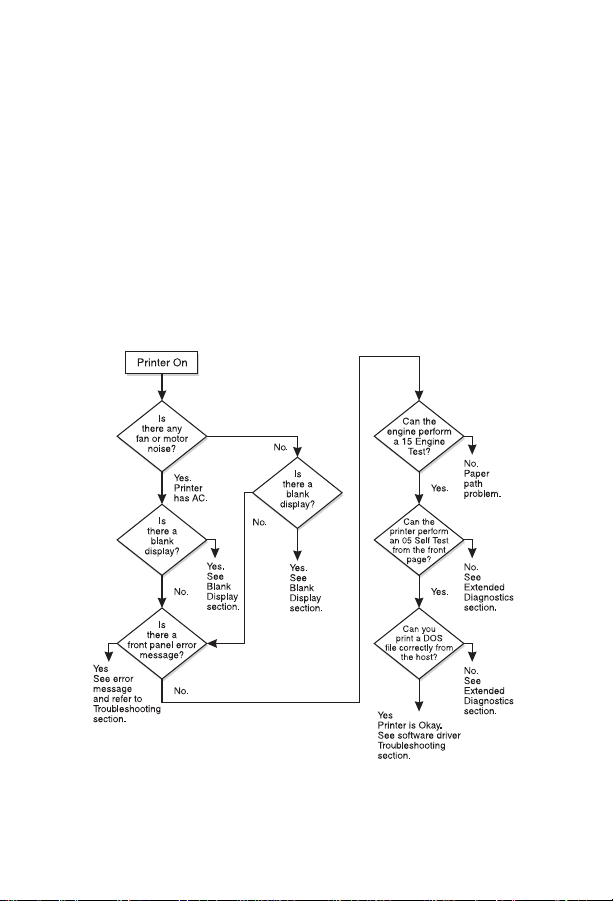
Basic troubleshooting process
The troubleshooting flowchart shown below highlights the process that
most quickly solves printer hardware problems. During its power-on
sequence, the printer verifies that its components are operating
correctly. If the printer fails to turn on correctly, use the steps shown in
the flowchart to troubleshoot the failure.
Note
User-accessible parts are blue-coded in the Color LaserJet and
purple-coded in the Color LaserJet 5/5M.
Troubleshooting flowchart
4 Chapter 1 – Troubleshooting control panel messages
EN
Page 11

Control panel messages
Alphabetical messages
Blank display
• Remove the cover over the display and look in the upper right-hand
corner of the vacuum florescent display (VFD). The dot should be
dark. If it is white, the vacuum in the display has been lost. Replace
the front panel.
• Turn off the printer. Then unplug and plug in the printer before
turning the printer on again.
• Check the 5 VDC on Fuse 1 on the control PCA, as shown in
“Voltage checks” in the printer service manual. The 5 VDC may be
missing.
• Reseat the display connections.
• Reseat the formatter.
• Check the fuses and connectors and listen for running fans and
motors when turning the printer on.
– If no fans or motors are running, there is no AC voltage to the
unit.
• Check the voltage at the test connector.
• Replace the formatter.
Config language
• Do not interrupt this installation sequence.
• This message is displayed when pressing and holding
turning the printer on. When the power-on self-test is completed, the
display language menu is available for configuration. This message
is not localized.
[Enter]
while
1
EN
Control panel messages
5
Page 12

Drum inst./drum number = xxx
• This message indicates that the printer has detected a new drum
and is waiting for the user to enter the number that is printed on the
bar-code label on the front of the drum. Press the [+] and [-] keys to
enter this information. The number xxx is a whole number between
1 and 127.
Note
The drum number (or drum ID) should match the number shown on
the self-test printout. (See “Understanding the self-test printout” on
page 64.)
Note
If the incorrect number was entered when the
number = xxx
message appeared, it can be corrected now.
Drum inst./drum
Error log
• To display this message, press and hold [Form Feed] while
power-cycling the printer.
• When the power-on self-test is completed, the error log is available
to use. See Chapter 7 in the printer service manual for instructions
on entering the Error Log Mode. This message is not localized.
Extended diagnostics
• Use extended diagnostics to test the printer when formatter,
memory (DRAM only), and MIO-related errors persist. The extended
diagnostics test exercises the ability of the f ormatter to communicate
across the MIO and with the memory. To perform the extended
diagnostics tests, see “Extended diagnostics” on page 110.
6 Chapter 1 – Troubleshooting control panel messages
EN
Page 13

FE font cart err/cycle power
Color LaserJet only
• The font cartridge was removed while the printer was online.
– This error occurs whether or not the cartridge was being
accessed.
– Power cycle the printer to clear this error.
Initializing NVRAM
• This message occurs when NVRAM must be initialized because one
or more values are incorrect.
• After the initialization is complete, the printer self-test message
appears.
Note
This message should only appear when the printer is turned on. It
should never appear during normal printer operation.
Installing new developer
Note
Do not interrupt this installation sequence.
• The new developer sequence has started.
– The installation sequence lasts about 3 minutes for the black
developer and 9 minutes for the color developer.
No fonts top/bottom/both font cartridge
1
Color LaserJet only
• The printer is not reading some (or all) of the indicated cartridges.
– To clear this error, reinsert the specified font cartridge and press
.
[Online]
• If the message persists, the indicated cartridge is bad and should be
replaced.
EN
Control panel messages
7
Page 14

Please verify drum number = xxx
• Re-enter the drum number for verification.
– Press the [+] and [-] keys to change the displayed number. If the
incorrect number was entered when the Drum inst. drum
number + xxx message appeared, it can be corrected now.
– This verifies that the correct number was entered.
Reinsert top/bottom/both font cartridge
Color LaserJet only
• Any or all of the font cartridges were removed while the printer was
offline and contained buffered data.
• Clear this error by reinserting the specified cartridge(s) and pressing
[Online].
Service Mode
• Service Mode is used to test printer functions by issuing commands
to the control PCA through the control panel. For more information
on this display panel message, see “Accessing Service Mode” on
page 87.
8 Chapter 1 – Troubleshooting control panel messages
EN
Page 15

Numerical messages
11.x Front tray empty
• The paper tray is not installed, or the tray is empty.
– Load paper.
– Check the paper-size detect board.
– Check that the switch actuators (on the tray) are not damaged.
11.4 Front tray empty
• The paper-out photosensor (PS8) senses an empty tray.
• If paper is in the tray, the sensor arm could be stuck or broken.
Troubleshoot PS8 as follows:
Remove the paper tray and open the top cover.
1
Check that the paper-size switch actuators on the tray are not damaged.
2
Check that PS8 is free throughout its entire range of travel and is properly
3
located in its mount.
Check that connector CN802 (on the controller) is fully seated.
4
If the error persists, perform the PS8 Service Mode Test as described
5
below.
PS8 Service Mode test
• PS8, the paper-out photosensor, can be tested in Service Mode as
follows:
Enter Service Mode (see “Accessing Service Mode” on page 87) and
1
select the Status Test Mode.
Enter the PS8 test address (10) and press
2
With no tray installed, the display will read
3
Open the printer, lift the paper guide, and move the sensor shaft through
4
its range of motion.
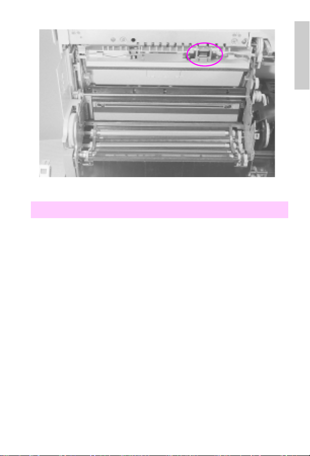
The display should change from low to high (
5
activated. If it does not change, check that the PS8 connector on the highvoltage power supply (HVPS) is fully seated, as shown in the figure below.
(The connectors are on the back of the HVPS.)
Replace the photosensor.
6
.
[Enter]
for paper tray empty.
0
to 1) as the photosensor is
0
1
EN
Control panel messages
9
Page 16
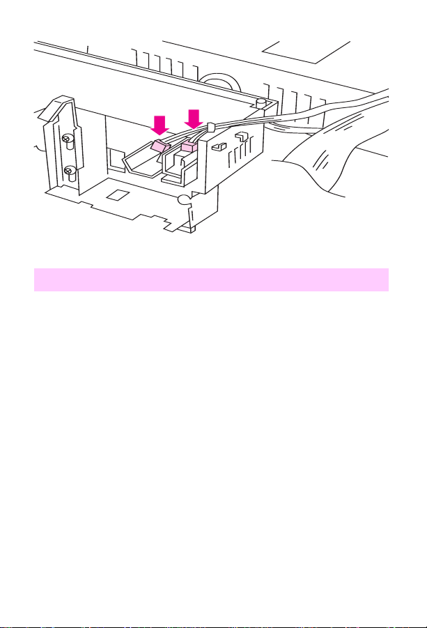
Photosensor PS8 connections on HVPS (HVPS inverted)
11.X Rear tray empty
• Check that the rear feed unit (RFU) is installed and that it has paper
in it.
• Remove the RFU and check that the connector is not damaged.
• Remove and reseat the RFU if paper is present.
Note
Do not remove or install the RFU when the power is on. The printer
only checks for the prese nce of the RFU when the printer is turned on.
10 Chapter 1 – Troubleshooting control panel messages
EN
Page 17

12 Close top or side door
• The printer’s top or side door is open or the door sensor has failed.
– Close the top or side door or replace the door sensor.
• One of the two interlock switch es (MS2 or MS3) m ay be defective . If
the following test proves that the switches are defective, replace the
interlock switch assembly as shown in Chapter 6 of the printer
service manual.
Note
Power cycle the printer and re-close both doors to confirm the
message before troubleshooting.
Test the interlock switch
WARNING!
Do not inhibit the free movement of the interlock switch. If this
mechanism is blocke d, voltage ma y be present when the top cove r is
open.
Open and close the top cover. If the message remains, open and
1
close the side door.
Open the side door and push the interlock mechanism with a flat-
2
blade screwdriver (see “Testing the interlock switches” on page 7-21
of the service manual), while running test 41 from Service Mode
(see Chapter 3).
If the message persists, remove the top cover and check that the
3
switch linkage is not bent.
Check that the switch connectors are in good repair. Toggle the
4
switches by pressing down on the metal tab over the switches.
If the linkage is not damaged, remove the switch assembly and test
5
it with an ohmmeter.
Replace the assembly if it is defective.
6
1
EN
Control panel messages
11
Page 18

13.1 Clear drum winding jam
Note
The locations of all sensors are identified on page 139.
• Paper is detected in the out of limit area of the print drum. The
drum-winding jam sensor indicates that paper is beginning to wrap
around the print drum.
– Turn the paper stack over end-to-end.
– Check that the paper meets HP paper specifications for the
printer.
– Check that media is not being re-fed into the printer.
– Check that the drum-wrap sensor is not blocked by opening the
side door and checking for paper wrapped around the drum.
• If no paper is seen, calibrate the drum-winding jam sensor by
entering into Service Mode (see “Accessing Service Mode” on
page 87“) and running test 47.
• See “Troubleshooting paper feed problems” on page 68.
13.2 Clear output jam
Note
The locations of all sensors are identified on page 139.
• Print media is jammed in the exit assembly because it failed to clear
the exit sensor (PS1) in the allotted time.
– Check that the sensor flag moves freely and that the sensor is
free of paper dust.
– Check that media is not in the sensor when the printer is turned
on.
– Te st th e operation of the sensors by entering Service Mode (see
“Accessing Service Mode” on page 87“) and running test 22.
• See “Troubleshooting paper feed problems” on page 68.
12 Chapter 1 – Troubleshooting control panel messages
EN
Page 19

13.4 Clear front tray input jam
Note
The locations of all sensors are identified on page 139.
• The printer detects a paper jam in the front tray area.
– Clear the front tray area.
• The paper failed to arrive at PS7 within the allotted time after SL1
(the paper feed solenoid) was engaged.
– Inspect the input an d registrati on area f or media . Transparencies
can be especially difficult to see.
– Test the operation of the sensors by entering Service Mode (see
“Accessing Service Mode” on page 87“) and running test 20.
• See “Troubleshooting paper feed problems” on page 68.
13.5 Clear fuser jam (CLJ)
13.5 Clear paper jam (CLJ5)
• Paper did not arrive at PS1 (exit sensor) in the allotted time. (See
the diagram on page 141 for the location of PS1.)
– Check that PS1 is free throughout its entire range of travel and
that media is not at the sensor when the printer is turned on.
– Check for paper dust in the sensor.
– Chec k to see if me dia has cleared the reg istra tion pl ate. If media
is present, check the operation of the registration plate solenoid
by running test 25 from the status and test section of the printer
service manual.
• Check to see if the transfer assembly is installed correctly.
• Test the interlock switch. (For instructions, see the section called “To
test the interlock switch” under erro r message 12 on page 11.)
• See “Troubleshooting paper feed problems” on page 68.
1
EN
Control panel messages
13
Page 20

13.6 Clear rear tray input jam
• The printer detects paper in the rear input area.
– Clear the RFU.
• The sensor (PS4) did not activate within the allotted time after M7
started. (See the diagram on page 142 for the location of PS4.)
– Repair the sensor.
– Check that PS4 is not blocked.
• Sensor PS4, the RFU paper sensor, failed to detect paper media
within the allotted time.
– Check that the sensor is not stuck.
– Check if media has been picked from the tray.
• Verify that the RFU is properly adjusted for the loaded media.
• See “Troubleshooting paper feed problems” on page 68.
13.7 Clear rear tray paper jam
Note
The locations of all sensors are identified on page 140.
• The printer detects a paper jam at the rear input area. This message
indicates that the paper was picked, but did not arrive at the
registration area (PS7), in the allotted time.
– Clear the jam and check the paper feed rollers.
– Check that sensor PS4 is not defective and that it is free
throughout its travel.
• See “Troubleshooting paper feed problems” on page 68.
13.8 Clear paper jam
• Paper is jammed in the paper registration area.
– Open the printer and remove the jammed paper.
• Paper may be on PS7 when the printer is turned on. (See the
diagram on page 141 for the location of PS7.)
– Check that PS7 is free.
• See “Troubleshooting paper feed problems” on page 68.
14 Chapter 1 – Troubleshooting control panel messages
EN
Page 21

13.8 Internal paper jam during warm-up
• Media was detected in the printer during warm up.
– Open the top cover and clear any media found inside the printer.
– If no media is found in the printer, check all sensors by running
the tests described under error messages 13.1, 13.2, 13.4,
and 13.5.
• Verify that all paper path sensors are not blocked and that the
detection flags are free throughout their travel.
• See “Troubleshooting paper feed problems” on page 68.
14.5 Replace collection box
16.5 Replace collection box
• Remove the toner collection box from the OPC drum assembly and
inspect the flexible diaphragm (in the top surface of the collection
box).
– If the diaphragm has been pushed above the collection box
surface by accumulated toner, the box is full. In this case, the
collection box must be replaced. Do not attempt to push the
diaphragm down to correct this condition.
• The excess toner collection box is monitored by PS3. (See the
diagram on page 141 for the location of PS3.) Perform the sensor
checks below to isolate the problem.
Toner collection box full sensor tests
Power cycle the printer.
1
Open the top cover and lower the print drum.
2
Pull the toner collection box out of the drum assembly.
3
Verify that the toner-full flag is moving freely (it should raise up as
4
you are pulling the toner collection box out of the assembly and drop
down once the collection box is remo ved).
Check to see if the toner collection box is full. If the toner collection
5
box is full, the diaphragm will be pushed out. If it is pushed out, then
the collection box is full and needs to be replaced.
1
EN
Control panel messages
15
Page 22

CAUTION
Do not try to continue using the toner collection box by pushing the
diaphragm down.
6 Check that the PS3 sensor is fully seated, clean, and connected
properly. (See the diagram on page 141 for the location of PS3.)
If these tests are not effective, perform the PS3 Service Mode test
described below.
Note
If the collection box is overfilled, the printer may need a thorough
cleaning. In addition, the excess toner auger (inside the print drum)
may be compacted or broken. The print drum may have to be
replaced.
PS3 Service Mode test
Note
The PS3 sensor flag is not accessible to toggle by hand. You must
have an empty collection box to perform this test.
1 P o wer cycle the printer and enter the Service Mode (see “Accessing
Service Mode” in Chapter 3.)
2 Select the status and test Mode of the Service menu.
3 Enter the PS3 test address (55), and press [Enter].
4 Install the empty collection box. If the display is high (1), the sensor
is stuck or defective.
5 If the display is low (0), pull out the collection box about an inch to
make the sensor flag rise. If the displa y does not change from 0 to 1,
the sensor flag is stuck or brok en or the sensor (PS3) is disl odged or
defective .
6 Check connector CN904 on the toner sensor PCA (Color LaserJet
only).
16 Chapter 1 – Troubleshooting control panel messages
EN
Page 23

14.6 Replace coating kit
• If this message does not clear when the coating pad kit is replaced,
the fusible link in the coating pad may not be contacting the leaf
spring in the fusing assembly or a coating kit with a blown fuse has
been installed.
– Reseat the coating pad.
Color LaserJet only
• If a new style fusing assembly with a purple handle has been
installed, then the fusible-link contacts are not making proper
electrical contact with the contact fusing spring assembly.
– Reseat the cleaning roller.
CAUTION
The printer should continue to print when returned online. The fuser
and main drive may be damag ed if the oil pad and cleaning roller are
not replaced as soon as possible.
16.5 Replace collection box
• See “14.5 Replace collection box.”
17.1 Install developer
17.2 Install developer
• The printer failed to detect either the black developer (for the 17.1
message) or the color developer (for the 17.2 message).
– If the developer is not installed, install it.
Power cycle the printer.
1
If the message persists, remove the suspected developer and
2
inspect the blade connectors that insert into the toner sensor PCA.
Check that they are clean and straight. Also check the toner sensor
PCA connectors.
Re-install the developer.
3
1
EN
Control panel messages
17
Page 24
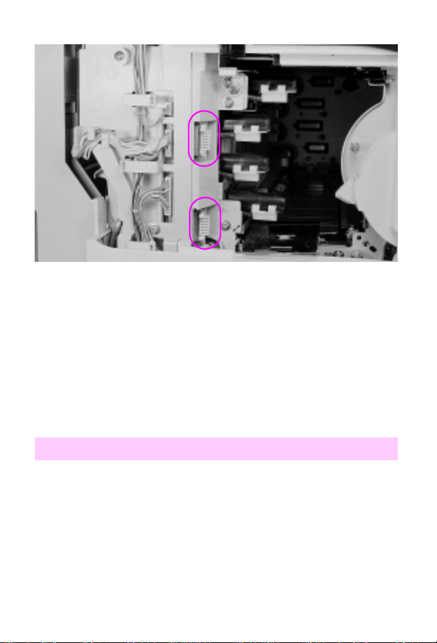
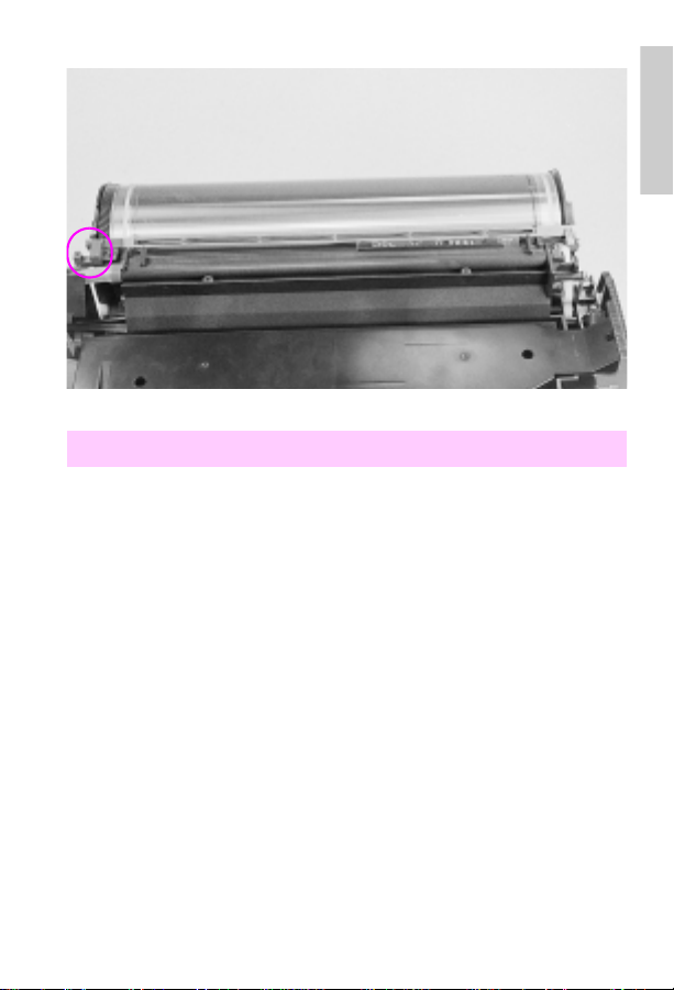
Ton er sensor PCA connections (circled)
4 Check all the connectors on the toner sensor PCA. Ensure that they
are all fully seated.
5 Check the wiring behind the power supply drawer for nicks or cuts
that may cause the signal line to short to ground. Reseat the
connectors if any are suspect.
6 Replace the toner sensor PCA if necessary.
7 If steps 1 through 6 do not resolve the problem, replace the
developer.
17.4 Install fuser
• The fuser is not installed, or the printer failed to detect the fuser.
1 Power cycle the printer.
2 If the message persists, remove and reseat the fuser.
3 Check that the fuser connectors are not damaged (no bent or
broken pins).
4 Check that nothing prevents the fuser from fully seating into its plug.
5 Check the connector (CN105) at the control PCA.
18 Chapter 1 – Troubleshooting control panel messages
EN
Page 25

Replace the fuser.
6
Replace the control PCA if necessary.
7
17.6 Install collection box
• The toner collection box or the print drum is not installed or is not
detected. The switches that post this message are inside the print
drum cartridge and cannot be tested directly.
Power cycle the printer to clear the message.
1
With the printer turned off and unplugged, inspect the print drum
connector (see the figure under “17.8 Reinstall drum”). Ensure that the
connections are not bent and that both the male and female ends are in
good repair and clean.
Ensure that nothing inhibits the print drum from fully seating into the
2
connection.
Check that CN101 on the control PCA and CN 254 on top of the
3
developer bias supply are fully seated.
Reseat the collection box and listen for an audible click.
4
If the collection box does not click into place, the leaf spring inside
5
the housing may be defective. Replace the print drum.
Remove the drum and very carefully clean the inside of the sensor,
6
using a cotton swab and isopropyl alcohol.
Re-install the drum.
7
1
EN
Control panel messages
19
Page 26

17.7 Remove drum cover
• The protective shipping cover for the print drum has not been
removed.
– Remove the drum cover (see the printer service manual for
instructions) or clear the drum wrap sensor.
• If the error persists, perform the status and test checks (see the
printer service manual) to test the drum wrap sensor.
• If the error still persists, perform the drum reflectance calibration
(Service Mode status and test address 47). Also see the procedures
for the 66.1 Jam sensor service message.
17.8 Reinstall drum
• This message indicates that the drum-winding sensor output is
abnormal during printing (see 66.1 Jam sensor error message).
• A jam sensor could be broken or defective, or a connection could be
loose.
1 Remove the print drum and inspect both sides of the connector as
shown in the “Print drum connector” figure below.
2 Re-install the print drum. Check that nothing prevents the print drum
from being fully seated into the printer.
Note
If the drum assembly is for a Color LaserJet 5/5M (the assembly will
be purple-coded), you will need to make sure the corona cleaning
lever on the drum is fully seated to the right.
3 Power cycle the printer.
4 Run test 47 in Service Mode (see Chapter3 for information on
accessing Service Mode).
5 Replace the drum cartridge assembly.
20 Chapter 1 – Troubleshooting control panel messages
EN
Page 27
Print drum connector (circled).
17.9 Reinstall fuser
• The fuser did not warm up correctly.
– Reseat the fuser.
• The fuser connection is not stable.
WARNING!
The fuser is HOT. Turn off the printer to allow the fuser to cool for at
least 30 minutes before beginning this procedure.
– Power cycle the printer to clear the message.
• If the message persists:
– Remove the fuser. Check that all the connectors are strai ght an d
clean.
– Reseat the fuser, being certain that all the connectors make
contact.
• If the message persists, replace the fuser.
1
EN
Control panel messages
21
Page 28

18.1 Clean transfer corona wire
• The paper-charging brush or the bias roller in the transfer assembly
is arcing.
– Power cycle the printer.
– Clean the transfer corona wire (see Chapter 2, “Cleaning and
maintenance”).
– Check connector CN701 on the control PCA and connector
CN702 on the HVPS.
– Replace the transfer assembly and try another test print.
– Replace the HVPS.
18.2 Reinstall drum
• The printer sensed a high-voltage leak in the print drum neutralizing
corona.
– Power cycle the printer to clear this error.
– Remove and reinstall the print drum. Try a test print.
– Check connector CN731 on the control PCA and connector
CN730 on the HVPS.
– Check the neutralizing corona contact for damage or
contamination. (see the “Neutralizing corona contacts” figure
below.)
– Replace the print drum.
– Replace the HVPS.
• The neutralizing corona may have arced.
– Clean the printer.
22 Chapter 1 – Troubleshooting control panel messages
EN
Page 29
Neutralizing corona contacts (circled)
18.3 Reinsert developers
• The printer detected a high-voltage leak in the de v elo per bias po wer
supply. (Although this is a developer bias fault, the print drum is
often the root cause of this failure.)
• The developer is not turning.
Remove each developer and check their pin contacts.
1
Check that each of the high voltage contacts on the developer bias
2
assembly is clean and located correctly.
Print several self-tests and look for repetitive defects. Replace the
3
print drum if repetitive defects appear.
Remove the print drum and check its surface for any bright metallic
4
spots, dents, or def ects that may indicate an arcing point (anywhere
in the green area). Replace the print drum if any defects are found.
Check CN601 on the developer bias supply and CN600 on the
5
control PCA.
Try a test print.
6
1
EN
Control panel messages
23
Page 30

• If the message persists, replace the print drum f ollo w e d b y the color
developer and the black developer if necessary.
7 Replace the developer bias power supply.
18.4 Clean transfer corona
• There is a high-voltage leak in the transf er belt, print drum, or HVPS.
– Power cycle the printer.
Note
If the problem will not repeat dependably , print transparencies in color.
Transparencies print at a slower speed with a higher transf er current.
• Clean the transfer corona (see Chapter 2, “Cleaning and
maintenance”).
• Check that the print drum contacts are clean.
• Remove the transfer belt assembly and print a test page.
• If a 13.x Paper jam message appears when printing without the
transfer assembly installed, the high-voltage leak is associated with
the transfer assembly.
– Check the transfer assembly contacts for proper alignment,
corrosion, etc. before replacing them.
• If the error persists, reseat the print drum. Then replace the print
drum followed by the HVPS if necessary.
24 Chapter 1 – Troubleshooting control panel messages
EN
Page 31

18.5 Reinsert developers
18.6 Reinsert developers
Note
18.5 Reinsert developers is for black developers.
18.6 Reinsert developers is for color developers.
Note
Do not replace devel opers until the actual cause h as been identified.
Replace the developers only if they are proven defective.
• The printer does not sense the changing output from the toner
concentration sensor that occurs with normal toner mo vement within
the developers.
– The developer is not selected.
– The developer drive gears are not engaging the developer.
– The developer drive gears do not rotate.
– The developer is not rotating.
• Reinsert the developer.
Note
If new developers are installed in the printer, toner compaction may
cause the toner concentration sensor to give an abnormal reading.
Remove the new dev eloper , shake it as described in Chapter 4 of the
printer service manual, and reinstall.
• Perform the following procedure to troubleshoot the 18.5 and 18.6
message:
Remove the developers and check that the drive and gears are not worn
1
and that no teeth are missing.
Remove the developer assemblies and print drum. Move the top cover up
2
and down. Check that the developer drive gears extend and retract and
are free throughout their travel. With the top cover partially closed, press
each developer drive gear and check that each has firm spring pressure.
Rotate the gears on each developer assembly by hand (this requires some
3
force). Check that they all hav e similar resistance. If the gears will not turn,
replace the developer.
Shake the developer as shown in chapter 4 of the service manual. Toner
4
may be compacted inside the developer.
1
EN
Control panel messages
25
Page 32

Examine the connectors on the developer and the toner sensor PCA for
5
damaged pins or connectors.
If symptoms still persist, follow the procedures listed below.
6
Service Mode tests
• Use Service Mode to check that the developers are rotating. This
test is especially useful because the status Mode displays the toner
concentration value while the developer augers rotate. To perform
this test, follow the steps below.
CAUTION
Do not perform this test with the RFU installed. Performing this test
with the RFU installed and the toner hopper cover removed will
damage the toner feed augers.
1 Enter Service Mode (see “Accessing Service Mode” in Chapter 3).
2 From the Status and Test Mode, select address 08.
3 Select subtest 0 for the 18.5 message, or address 1, 2, or 3 for the
18.6 message. Once selected, press [Online] to start the test. When
the test starts, the control panel displays the toner concentration
value for the selected developer. If the developer drive gear rotates,
the toner concentration sensor value displayed on the control panel
should fluctuate slightly.
4 If the gears do not rotate, check the developer rotation as follows:
A Remove the RFU, if installed.
B Remove the toner hopper cover.
C Run the Service Mode test again.
D Watch the developer drive gears at the rear of the printer. They
should turn when the test is started. Make sure you are looking
at the developer drive gear and the developer gear during this
test. (The black drive gear is the most difficult to see.)
E If the gears do not rotate, perform the mechanism alignment
checks.
5 If the gears rotate and the toner conce ntration sensor valu e does not
fluctuate, check the electrical connections between the developer
and the control PCA.
26 Chapter 1 – Troubleshooting control panel messages
EN
Page 33

If the electrical connections are OK, replace the toner sensor PCA.
6
If the message persists, replace the developer.
7
Mechanism alignment checks
• Misalignment between the developer drive assembly, the toner
hopper assembly, and the printer frame may cause 18.5 and 18.6
errors. Check the f ollowing items for a lignment when troub leshooting
this error.
Remove the developer and check to see if the developer casing is
1
bent. To do so, follow these instructions:
Place the developer on a flat surface with the back of the
A
developer toward you.
Push the developer forward inside the casing.
B
If the developers do not mov e f or ward un til the bias contact p in is
C
against the casing on the left side, the casing is bent.
Replace the developer assembly.
D
The printer frame has detents that position the developer drive
5
assembly correctly on the printer frame. Ensure that the assembly is
properly seated on these detents. Improper seating will misalign the
developer drive assembly with the developers and the toner hopper
assembly . If misa ligned, loosen the screw s, align the de ve loper drive
assembly on the detents, and then tighten the screws.
The developer drive assembly aligns with the toner hopper
6
assembly through an alignment pin located on the developer drive
assembly. Check that the alignment pin is straight and that the toner
hopper is fully seated. If the alignment pin is bent, replace the
developer drive assembly.
If the alignment pin is not damaged, remove the screws that hold the
7
toner hopper in place, and then:
Slide the toner hopper towards the left side of the printer (to the
A
right when viewed from the rear of the printer).
1
EN
Control panel messages
27
Page 34

B Check the gear cluster on the toner hopper for bent sheet metal.
If the toner hopper select shaft is out of its bushing or if the b u shing is not mounted correctly in the sheet metal, the sheet metal
may be bent. If the gear cluster is damaged, replace the toner
hopper assembly.
C Check to see if the activation arms for the toner hopper lockout
fingers are against the select cams. If the arms are on the cams,
check the toner hopper lock solenoid (SL6), located on the left
side of the toner hopper, for binding and correct operation.
D If the toner hopper assembly is functioning correctly, slide the
assembly back into position. Align it with the developer drive
assembly being careful not to damage the gear cluster. Reinstall
the toner hopper screws.
19.x User maintenance
• A printer consumable has exceeded its maximum life . Press [Online]
to continue. The printer will continue to print, but print quality will
degrade until the indicated consumable is replaced.
CAUTION
The main drive gears could become damaged if the fuse r is allo w ed
to remain past its maximum life in the printer.
• If the indicated consumable has been replaced:
Reseat the consumable.
1
Check both sides of the connector for bent pins.
2
Power cycle the printer.
3
Verify that the fuse for the consumable is not blown. The drum,
4
developers, transfer, fuser, and coating kit are fused. If the fuse is blown
when a new consumable is installed in the printer, the consumable will not
be detected as a “new” part.
Note
Do not return a consumable to stock once the fuse is blown.
Try another of the indicated consumables.
5
Check the self-test print for any value that is inconsistent with the
6
perceived actual cumulative usage. If a value is suspect, investigate the
possibility of a NVRAM problem. If necessary, contact your local response
center.
28 Chapter 1 – Troubleshooting control panel messages
EN
Page 35

20 Memory overflow
• More data has been received from the host than fits in internal
memory.
– Press
printer memory is printed.
• If the message persists, install more memory.
to continue printing. Only the data that fits in
[Online]
21 Memory out
• The printer has run out of memory. Imaging the current job cannot
continue until the engine clears memory.
– Press
• If this error persists, install additional memory.
to clear memory. This results in data loss.
[Online]
22 I/O config error
• The computer is not obeying the pacing mechanism of the MIO link.
This causes the printer’s receiving buffer to overflow during a busy
state.
23 MIO not ready
• The MIO card cannot accept data.
– Print the self-test page for more information.
– The MIO card could be defective.
• If the message persists, reseat the MIO card and ensure it is
properly connected to the network. If necessary, replace the MIO
card.
1
EN
Control panel messages
29
Page 36

24 Busy moving toner
• The printer is adding toner to the developers. If this message is
displayed frequently, check for faint print. If several pages of heavy
toner coverage are being printed, this message may not indicate an
error. If the message persists, the toner feed auger may not be
turning or a toner sensor may be defective.
1 Power cycle the printer.
2 Check the toner level in the toner hopper assembly by manually
opening each hopper. If any of the hoppers are completely empty,
the toner sensor for the empty hopper may be defective. Use the
Service Mode status and test (address 01) to test the toner level
sensors.
Note
The toner sensors on the hoppers are piezo -electric. When the toner
falls below the level of the sensor, the sensor output is audible.
However, the high-pitched sound may be out of hearing range for
some people.
3 If the hoppers have enough toner to cover the sensor, and the
message persists, check the toner hopper auger operation as
follows:
A Remove the RFU.
B Manually open the hoppers and watch the paddles while printing
the demo page.
C If the paddles turn, the problem is in the hopper augers . Replace
the toner hopper assembly.
D If the paddles do not turn, print the demo page 10 times. Watch
that the toner hopper supply shaft rotates, that the hopper select
shaft engages the hopper clutch, and that the toner supply
augers turn.
E If the toner supply shaft does not rotate, perform the toner supply
solenoid test as described below.
30 Chapter 1 – Troubleshooting control panel messages
EN
Page 37

Toner supply solenoid test
Test the toner supply solenoid (SL3) and supply augers as follows:
Enter the Service Mode (see “Accessing Service Mode” in
1
Chapter 3) and select test address 52.
Remove the RFU and the back cover. Listen for the solenoid to
2
actuate.
30 PostScript error xx
• The printer encountered a PostScript error indicated by XX.
– Press
to continue. The current job is canceled.
[Online]
Note
For PostScript errors, look at the program that is being sent, rather
than at the printer unless every Po stScript file comes up with the same
error.
30 PostScript error 00
• An attempt was made to add an item to a dictionary that is full. This
may be a driver incompatibility problem.
– Select a different PostScript driver and resend the print job.
30 PostScript error 01
• An attempt was made to place too many dictionaries on the
dictionary stack. This may be a driver incompatibility problem.
– Select a different PostScript driver and resend the print job.
1
30 PostScript error 02
• An attempt was made to remove more dictionaries from the
dictionary stack than were available. This may be a driver
incompatibility problem.
– Select a different PostScript driver and resend the print job.
EN
Control panel messages
31
Page 38

30 PostScript error 03
• The execution stack is too large. Procedure invocation is nested
deeper than PostScript allows. This may be a driver incompatibility
problem.
– Select a different PostScript driver and resend the print job.
30 PostScript error 04
• An attempt was made to access an array, dictionary, file, or string
object incorrectly.
30 PostScript error 05
• An incorrect exit was executed.
30 PostScript error 06
• An incorrect access string specification to the file operator occurred.
30 PostScript error 07
• The operand to make font or set font is not a well formed font
dictionary.
30 PostScript error 08
• An incorrect restore was attempted.
30 PostScript error 09
• An error occurred during the execution of one or more of the file
operators.
30 PostScript error 10
• A PostScript implementation limit was exceeded.
32 Chapter 1 – Troubleshooting control panel messages
EN
Page 39

30 PostScript error 11
• An operator requiring a current point was exceeded while the
current path was empty.
30 PostScript error 12
• A numeric operand’s value is out of range.
30 PostScript error 13
• An attempt was made to push too many objects on the operand
stack.
30 PostScript error 14
• An attempt was made to pop an item from an empty operand stack.
30 PostScript error 15
• The PostScript scanner encountered text that does not conform to
the PostScript syntax rules.
30 PostScript error 16
• The PostScript interpreter timed out waiting for the user to manually
feed paper, waiting for data from the computer, or because a job
took too long to complete.
1
30 PostScript error 17
• An operand was encountered that is not the correct type, such as a
number when a string is required.
30 PostScript error 18
• A name was encountered that cannot be found since it was
previously undefined.
EN
Control panel messages
33
Page 40

30 PostScript error 19
• A file identified by a name string operand of the file or run operators
cannot be found or opened.
30 PostScript error 20
• An overflow, underflow, or meaningless result of a numeric
calculation (such as division by zero) occurred.
30 PostScript error 21
• A clear-to-mark or count-to-mark operator could not find the
required mark on the stack.
30 PostScript error 22
• An operator object was executed for which the interpreter has no
built in action.
30 PostScript error 23
• An error occurred in virtual memory.
30 PostScript error 24
• The systemdict quit operator was executed causing the PostScript
interpreter to re-initialize virtual memory. All non-persistent
information was lost.
30 PostScript error 25
• A PostScript firmware failure occurred. This is associated with
normal error handling and not with hardware.
30 PostScript error 26
• A “setpagedevice” request cannot be satisfied.
34 Chapter 1 – Troubleshooting control panel messages
EN
Page 41

30 PostScript error 27
• An external interrupt request was received by the PostScript
interpreter.
30 PostScript error 28
• A named resource sought by the findresource operator does not
exist.
40 I/O data error
• A data error has occurred while receiving data from the computer.
Press
the printer and computer.
to continue printing. Check the connection between
[Online]
48 Invalid job/aborting job
• The printer does not recognize the language it is being switched to.
– This message remains in the display until it receives a valid
language.
50.x Fuser service
• The printer senses that the fuser temperature is incorrect for the
application. The voltage read at the upper fusing roller thermistor
momentarily exceeded the limit. Leave the printer on for 20 minutes
(this gives the internal clock time to count do wn and rese t) and th en
power cycle the printer to clear this message. This message can
also be reset by going into the service Mode, register adjust, and
setting address 47 to 00. If the message persists:
• Check that the fuser connector is in good repair (no bent or broken
pins).
• Open and close both doors during the warm-up period. If the
message appears immediately, replace the fuser.
• Make certain the fuser can be fully seated into the printer and that
toner has not accumulated around the fuser area.
1
EN
Control panel messages
35
Page 42

• Check the connectors on the fuser, and check the connectors in the
printer that interface with these fuser connectors.
• Check connector CN105. CN105 is labeled on the control PCA.
(See the main wiring diagram in Chapter 8).
• Replace the fusing assembly.
50.1 Fuser service error
• The fuser temperature is too high for the application.
– Leav e the pow er on f or 20 minutes while the printer counts down,
then power cycle the printer to clear this error or use address 47
in the register adjust section of the Service Mode to reset this
message.
– Check the fuser connections.
50.2 Fuser service error
• The fuser temperature is too low for the application.
– Leav e the pow er on f or 20 minutes while the printer counts down,
then power cycle the printer to clear this error or use address 47
in the register adjust section of the Service Mode to reset this
message.
– Check the fuser connections.
50.3 Fuser service error
• The fuser temperature sensor is open.
– Leav e the pow er on f or 20 minutes while the printer counts down,
then power cycle the printer to clear this error or use address 47
in the register adjust section of the Service Mode to reset this
message.
– Check the fuser connections.
36 Chapter 1 – Troubleshooting control panel messages
EN
Page 43

50.4 Fuser service error
• There is a fuser temperature error caused by erratic sensor values.
– Leave the power on for 20 minutes, and then power cycle the
printer to clear this error or use address 47 in the register adjust
section of the Service Mode to reset this message.
52.1 Engine NVRAM error
• This error indicates a fail ure to read the N VRAM on the control PCA.
To troubleshoot this problem:
Power cycle the printer.
1
If for some reason the NVRAM was remov ed from its soc k et, ensure
2
that there are no bent pins and that they are all in their correct
position.
If the error persists, contact your local response center for
3
assistance in evaluating NVRAM viability.
52.2 Engine NVRAM error
• A developer with a blown fuse is being installed into a new printer.
• The NVRAM data could be corrupt.
– The printer checks an address in NVRAM for the status of the
engine. If the status returned is new, then the printer checks the
developers to see if the fuses are ne w (clo sed). If the fuses ha ve
been blown, then the
fuses are blown on the developers use an ohmmeter across pins
5 and 6 on the color developer, and pins 4 and 6 on the black
developer (see the main wiring diagram in Chapter 8). (Pin 1 is at
the bottom of each connector.) If either developer has a blown
fuse, replace the developer.
• If the printer is new, replace the developer. If the printer is not new,
troubleshoot as 52.1 Engine NVRAM error.
52.2 error
is displayed. To check if the
1
EN
Control panel messages
37
Page 44

53 Laser error
• The printer has detected a laser diode error.
– Power cycle the printer.
• If the error persists, reseat connectors CN300 and CN101. (See
Chapter 8, “Wiring diagrams” for the locations of these connectors.)
• If the connectors are in good repair, replace the laser scanner
assembly.
53 Laser error/service
• The laser signal is unstable.
1 Press [Online] to continue.
2 Power cycle the printer.
3 Open, then close the side door.
4 Check the side door interlock.
54.x Engine error/service error
The engine reported one of five types of failures or errors as listed
below. Try to clear the errors by pressing [Online]. If the message
persists, perform the appropriate procedure described below for the
applicable 54 error message.
54.1 Engine error/service
• The scanner motor (M6) did not reach the correct speed in the
allotted time.
– Power cycle the printer.
• If the motor spins up and the error persists, perform the following
procedure.
1 Check CN104 and CN350 on the optics assembly.
2 Inspect the wires behind the power supply drawer for nicks or cuts
on the insulation.
3 Measure the 24V DC.
38 Chapter 1 – Troubleshooting control panel messages
EN
Page 45

Replace the laser scanner assembly.
4
Replace the control PCA.
5
54.2 Engine error/service
• The printer detected an error in the 24V DC supply.
– Power cycle the printer to clear the error.
• If the error persists, check the 24V DC line.
– If the 24V DC voltage is missing, replace the DC power supply.
Note
The actual measured voltage should be approximately 22V DC.
• A defective or misaligned interlock switch can also cause this error.
– Use a screwdriver to push the interlock mechanism in the
direction shown in the printer service manual, page 7-21, Figure
7-4.
• If the message clears, adjust the tab on the side door which
operates the interlock mechanism.
• If the message persists, turn off the printer and check the interlock
mechanism, connectors, and cabling.
• Check fuse F5 on the DC power supply and fuse F2 on the control
PCA.
54.3 Engine error/service
Note
Do not replace any dev elopers until the cause of the error is identi fied.
Replacing developers without identifying the cause of the error will
only mask the problem and could lead to an other service call from the
customer.
• A toner concentration error occurs when the toner concentration
sensor reading is at a minimum or maximum value. This error can
be caused by:
– a defective toner concentration sensor
– failure of the toner hopper sensor or toner supply mechanism
– too much or too little toner in the developer
1
EN
Control panel messages
39
Page 46

– a defective toner sensor PCA
– incorrect NVRAM values. Incorrect NVRAM values can be
caused by:
not installing the correct NVRAM on the control PCA
•
installing the NVRAM incorrectly
•
a defective NVRAM
•
installing a used devel o pe r.
•
Incorrect NVRAM values usually cause too much toner to be
delivered to the developer. Failure of the toner hopper sensor or
toner supply mechanism is usually associated with not enough ton er
being delivered to the developer. To determine the cause of this
error follow the steps below:
1 Power cycle the printer.
2 Run se v eral self-test pa ges to see if the e rror returns. You should be
able to print at least one self-test page before the 54.3 error
message reappears.
3 If the error returns, look at the self-test page and check for faded or
bold colors.
4 If a color looks fa ded, the problem will most lik ely be associated with
a defective toner hopp er sensor or the toner supply mechanism. If
any color looks bold, then too much toner may have been added to a
developer.
5 To identify which developer is reporting the error, run the toner
concentration test shown below. A value of 127 or 63 on the front
panel is an indicator for the developer reporting the error.
6 See “Faint print” on page 157 for the procedure to troubleshoot a
problem with faded print.
7 If a color looks bold on the self-test page, the problem can be
caused by one of the following:
– an incorrect NVRAM value
– the wrong NVRAM was installed on the control PCA
– a developer, which is not the most recent one to be initialized by
the printer, has been installed
40 Chapter 1 – Troubleshooting control panel messages
EN
Page 47

• The NVRAM values correspond to the last developer that was
initialized in the printer. Even if the developer currently installed was
initialized in the printer, if it was not the last de veloper initialized, the
NVRAM values are not correct.
If the wrong developer was installed, reinstall the correct developer.
8
If the wrong NVRAM was installed, reinstall the correct NVRAM.
9
If the correct NVRAM or the correct developer(s) is not available, a
10
new developer(s) must be initialized in the printer.
For other NVRAM associated problems, contact your local response
11
center.
Toner concentration test
Note
The toner concentration test is useful whenever the printed page
displays characteristics of having either low toner concentration or
high toner concentration. The procedures to correct low and high
toner concentration are discussed later in this chapter.
Print a self-test page and note the relative humidity reading.
1
Power cycle the printer and enter the Service MODE (see
2
“Accessing Service Mode” in Chapter 3). Select the Register Adjust
function of the Service Mode (see Chapter 3 for instructions on the
register adjust function) to obtain the data values contained in the
NVRAM addresses listed below.
NVRAM addresses
1
Color Black Yellow Magenta Cyan
Address
Data
Example:
Page
count
EN
30 29 28 33 32 31 36 35 34 39 38 37
AA00BB16CC23AA00BB08CC28AA00BB08CC28AA00BB08CC
AABBCC AABBCC AABBCC AABBCC
Control panel messages
15
41
Page 48

3 Press the [Form Feed] and [Reset] keys to select the desired
NVRAM address. When the desired NVRAM address is displayed,
press [Enter] to display the value held at that address. For example,
if the displayed NVRAM address is 29 and the value held at that
address is 18, then the display will read:
Current Value
029 ReadOnly 18
Record the address and the value it contains. To clear this display
and toggle back to
Enter Address xxx
, press [Enter] again.
Repeat this procedure until the NVRAM values for all of the
addresses in the “NVRAM addresses” table ha ve been obtained and
recorded.
4 The current cumulative page counts for each of the developers can
now be constructed from the data you have obtained. See the
following e x amples:
Examples
Address: 30=00, Address 29-16 and Address 28-23. The black page count is
001623.
Address 33=00. Address 32=08 and Address 31=28. The yellow page count is
000828.
Address 36=00. Address 35=08 and Address 34=28. The magenta page
count is 000828.
Address 39=00. Address 38=08 and Address 37=15. The cyan page count
:
is
000815.
Note
Do not use the black and color page counts from the self-test page
(these counts indicate the total cumulative page counts for the printer ,
which are usually different than the page counts for the developers).
5 Power cycle the printer and enter Service Mode again. Select the
status and test function from the Engine Service Status/Test Mode.
6 Follow the Status and Test Mode flow charts (pages 88 and 90 until
you come to the
Enter Address AB
several times to increment to AB = 08 (see the toner concentration
values table on page 43).This sets the system to select test number
08 (developer rotation).
display. Press [Form Feed]
42 Chapter 1 – Troubleshooting control panel messages
EN
Page 49
7
Press
[Enter]
to display:
Enter Subset #
08 0
Enter the value of the subset # that is appro priate for the developer;
select the number from the target toner concentration table below.
8
Press
[Enter]
to display:
Online to Start
AB x YYY
When
values of YYY will be displayed. After allo wing the rotation/update to
run for at least 30 seconds, record the
displayed. While the rotation/update is in progress, the following
message displays:
is pressed, the developer will rotate and updated
[Online]
value that is being
YYY
Reset to Cancel
AB x YYY
Make sure to record the displayed
developer. Press
Use the following table to convert the number displayed on the
9
control panel to the actual concentration value.
to end the rotation/update.
[Reset]
value for the appropriate
YYY
Toner concentration values
1
Displayed value (
Less than 64 Same as displayed value
64 or larger 64 minus the displayed value
Using the Internal Humidity reading from the self-test page and the
10
page count for the developer (from NVRAM), locate the target toner
concentration value for each developer from the target toner
concentration table.
If the toner concentration value (derived from step 10) is more than
11
12 points lower than the target value, then the toner concentration in
the developer is too low. If the toner concentration value is more
than 12 points higher than the target value, then the toner
concentration value is too high. Try the following techniques for
correcting low or high toner concentration problems.
EN
) Actual toner concentration value
YYY
Control panel messages
43
Page 50

Correcting toner concentration levels
Low toner level
Effective resolution of a low toner concentration problem r equires
correction of the root cause. Here are some likely causes:
• Poor distribution of the toner mix in the developer cartridge at the
time of its initial use in the printer.
– It is possib le that shipment or stor age of the de veloper resulte d in
some toner/carrier segregation. This can result in erroneous
calibration of the toner-concentration sensor when the new
developer is initialized in the printer. Toner/carrier segregation
can result in toner-rich compaction in the concentration-sensor
zone. This presents a worst-case condition f or sensor cali bration
error. Properly shaking new developer before initialization, as
prescribed in the installation instructions and in the user guide f or
the printer will usually prevent this condition. Correcting an
improper initialization is not practical. If print quality is noticeably
deficient, replace the developer.
• Use of a replacement developer that has not been properly
initialized in this printer.
– This can cause a toner concentration error. Short-term use of a
previously initialized developer for troubleshooting is acceptable,
but the original (properly initialized) developer should be
reinstalled after troubleshooting is completed ; otherwise, install a
new developer.
• Compaction of toner in the replenishment mechanism (auger
assembly or feed-in port).
– This can result in toner depletion.
• Empty auger tubes.
– If service efforts have resulted in replacing the toner hopper
assembly, the toner auger tubes may not have been filled. To
correct this problem:
Use Test 19 in Service Mode to unlock the hoppers.
1
Fill the hoppers with toner, if necessary.
2
Manually rotate (downwards) the large white gear on the side of each
3
hopper to fill the auger tubes. Do this while holding the auger tube
shutter open at the developer end of the auger tube with something in
place to catch any toner that escapes, such as a tissue or index card.
44 Chapter 1 – Troubleshooting control panel messages
EN
Page 51

• Incomplete toner fill in the auger tubes.
– Ensure a complete toner fill in the auger tube associated with
any developer (which has been revealed by the Toner
Concentration Test). This can be accomplished in the manner
described above (step 3).
• Incomplete toner concentration test.
– After completing any corrective action(s) for low toner
concentration, such as described above, run the Toner
Concentration Test again. Remember, it takes some time for the
replenished toner to be uniformly distributed through the
developer; the test should be allowed to run for at least 30
seconds before making the front panel reading (
resulting
return to normal toner concentration on its own during regular
operation. If it “errors out” or if the displayed value is greater than
100, manually feed toner (step 3, above) and repeat the Toner
Concentration Test. Failure to improve toner concentration
values with these measures may indicate failure of the toner
concentration detection circuitry or the toner replenishment
mechanisms. Installation of a new developer may appear to
correct the problem, but if the detection system, replenishment
system, or both are malfunctioning, the problem can return.
value is in the range 000 to 100, the printer will
YYY
value). If the
YYY
High toner level
• Recovering from this toner condition is not as easy as recovering
from a low toner level. It is important that the root problem for this
condition has been clearly identified; otherwise, the problem will be
masked for only a short time and the original problem will eventually
occur again.
Print a solid fill page for the color generating the error. Continue to
1
print this page until the error no longer appears.
If far too much toner is in the developer, the developer will need to
2
be replaced.
1
EN
Control panel messages
45
Page 52

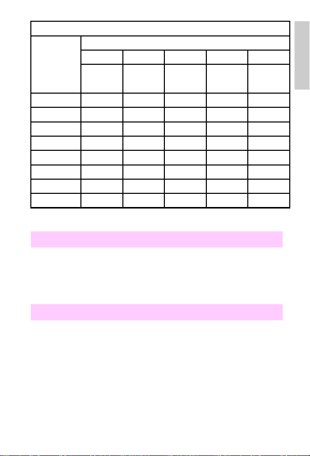
Target toner concentration
Target toner concentration
Developer
count
>0 4 4 3 3 2 2 2 1 2 0
>40 8 8 6 6 4 4 4 2 4 0
>80 12 12 9 9 6 6 6 3 6 0
>120 15 15 11 11 8 8 8 4 8 0
>160 18 18 13 14 9 9 9 5 9 0
>230 21 21 15 16 11 10 11 6 11 0
>310 24 24 17 18 12 12 12 6 12 0
>400 27 27 19 20 14 13 14 7 14 0
>500 30 30 22 23 16 14 16 8 16 0
>650 33 33 24 25 17 16 17 9 17 0
>800 36 36 26 27 19 17 19 9 19 0
>1000 39 39 28 29 20 19 20 10 20 0
>1250 42 42 30 32 22 20 22 11 22 0
>1500 45 45 32 34 23 22 23 12 23 0
>1750 48 48 35 36 25 23 25 12 25 0
>2000 50 50 38 36 26 24 26 11 26 0
>2750 47 47 34 35 24 23 24 10 24 0
>3500 44 44 32 33 23 21 23 9 23 0
>4250 41 41 30 31 21 20 21 8 21 0
>5000 38 38 27 29 20 18 20 6 20 0
>5750 35 35 25 26 18 17 18 4 18 -2
>6500 32 32 23 24 17 15 17 2 17 -4
20% or less 20-29% 30-39% 40-59% >60%
KY
M
C
Relative humidity
KY
M
C
KY
M
C
KY
M
C
KY
M
C
46 Chapter 1 – Troubleshooting control panel messages
EN
Page 53
Target toner concentration (continued)
Developer
count
>7000 28 28 20 21 16 13 16 0 16 -6
>7500 28 28 20 18 15 12 15 -2 15 -8
>8000 28 28 20 18 15 10 14 -4 14 -10
>8500 28 28 20 18 15 8 13 -6 13 -12
>9000 28 28 20 18 15 8 12 -6 12 -14
>9500 28 28 20 18 15 8 11 -6 11 -16
>10000 28 28 20 18 15 8 10 -6 10 -18
>14000 28 28 20 18 15 8 9 -6 9 -20
20% or less 20-29% 30-39% 40-59% >60%
KY
M
C
Relative humidity
KY
M
C
KY
M
C
KY
M
C
KY
54.4 Engine error/service
• A pressure cam home position sensor (PS2) error has occurred.
The pressure cam did not sense the home position with in 4 seconds
after the initial rotation of the pressure cam.
– Power cycle the printer.
54.4 Cam home position sensor
1
M
C
• The cam sensor (PS2) did not detect home position. This message
can also occur with general printer disassembly involving the control
PCA or the developer bias supply.
– Since PS2 is located on the back of the developer bias supply,
make sure it is reconnected if the developer bias supply was
removed. (See page 139 for the location of PS2.)
– Make sure that the connector (CN802) on the control PCA is fully
seated.
EN
Control panel messages
47
Page 54

• Other symptoms include the following:
– complete or partially blank pages
– smeared vertical line on the front of the page
– smeared toner image on the back of the page
Note
This message might appear as a result of the drive gears being
installed incorrectly causing a loss of cam timing. Follow the cam
timing procedure in Chapter 6 of the printer service manual to correct
the cam timing problem.
• To troubleshoot the 54.4 message:
1 Open the top cov er and locate the tab that activ ates the A C interlock
switch. The tab is located to the right and belo w th e black dev el oper
and is part of the developer drive assembly. If the tab is bent, bend
the tab until it is aligned with the plunger.
2 If the tab is stra ight, turn the printer on while chec king the 24V DC at
the test connector, which is located on the rear of the printer.
Note
The actual measured voltage will be approximately 22V DC.
3 If no voltage is present, check the interlock switches on the left side
of the printer and verify that they are working correctly. Replace the
switch mechanism if defective.
4 If the switch mechanism is oka y and the v oltage does not reach 22V
when the printer is turned on, replace the DC power supply.
5 If the DC voltage is OK, remove the right-side cover and watch the
AC motor (M2) to see if it turns as you turn on the printer.
6 If M2 does not turn, turn off the printer and unplug the power cord.
Disconnect the connector to M2 and connect a voltmeter.
WARNING!
With the printer turned on, there is 120/240V AC at this connector . Do
not cross the leads of your meter or touch them with your hand. Doing
so will cause damage to the printer or result in electrical shock.
7 Plug the power cord into the printer and turn the printer on. Watch to
see if the AC voltage is supplied.
48 Chapter 1 – Troubleshooting control panel messages
EN
Page 55

If power is available replace M2.
8
If no power is available, replace the AC power supply in the Color
9
LaserJet or the DC power supply in the Color LaserJet 5/5M.
If the power supply does not solve the problem, follow the
10
procedures for the cam service Mode test to verify that the sensor is
operating correctly.
Run test 53 in service Mode to verify that the solenoid is operating.
11
You should be able to hear when the solenoid turns on or off.
Replace the solenoid if defective. A good solenoid should have a
resistance value of approximately 56 ohms.
If the solenoid is okay when the resistance is measured and
12
everything else noted above has been checked, replace the control
PCA.
Cam Service Mode test
Enter the status and test section of the Service Mode (see
1
“Accessing Service Mode” in Chapter 3).
Select address 51.
2
Open the top cover, remove the print drum, and release the cam
3
solenoid (SL4), as shown in the figure below.
Turn the gear train slowly, and watch the control panel display. The
4
status display will change from 000 to 001 when the cam home
sensor is activated.
If the home sensor reading does not change, check the following:
• The developer bias supply is fully seated.
• The cam home sensor is mounted in the printe r frame correctly.
• The sensor connector is in good repair.
• If all of the above are okay, replace the sensor PS2. (See page 141
for the location of PS2.)
• When checking the cam home solenoid, run a demo page. With the
top cover removed, check that the solenoid releases. If it does not,
replace solenoid (SL4) and its clutch, and then check th e cam timing
as shown in Chapter 6 of the printer service manual.
1
EN
Control panel messages
49
Page 56

Releasing the pressure cam home solenoid
54.5 Engine error/service
• A developer home position sensor (PS6) error has occurred. The
developing switch position sensor did not detect the home position
within 4 seconds after the initial motion of the pressure cam.
54.5 Developer home position sensor
• The printer failed to detect the developer cam home position within
4 seconds after the initial rotation of the pressure cam.
• The sensor (PS6) is defective. (See page 141 for the location of
PS6.)
Note
If this message occurs after general printer disassembly around the
control PCA, the sensor PS6 may be disconnected. See chapter 5
under “Sensors” in the printer service manual to locate PS6, and
check that it is plugged in both at the sensor and at the control PCA
(CN802).
50 Chapter 1 – Troubleshooting control panel messages
EN
Page 57

54.5 Service Mode test
Select the Service Mode Status and test address 51 and check that
1
the developer drive motor rotates.
If the developer drive motor (M2) does not rotate, check the
2
connectors. If the connectors are proper and M2 still does not rotate,
replace M2.
If the developer d rive mo tor rotates , use the status Mode test (50) to
3
test the developer home sensor. (It may be necessary to turn the
gear train by hand to activ ate this sensor .) The displa y changes from
00 to 01 when the sensor is activated.
If the sensor does not activate, check that the sensor is properly
4
connected at both ends.
If the connections are correct and the sensor is properly mounted,
5
replace the sensor, PS6.
55.X Engine CMD error
• All 55.X messages indicate that the formatter and the control PCA
have failed in some aspect of their communication. When
troubleshooting this message:
– Reseat the formatter into its connector and perform a test print.
– If the message persists, remove the formatter, and check that
none of the formatter connector pins are bent or broken. (This is
not a probable cause if the control PCA or formatter have never
been removed.)
– Check the 5V fuse on the control PCA. If the fuse is blown,
attempt to determine why the fuse blew, then correct the
condition.
– If the message persists, replace the formatter, followed by the
control PCA if necessary.
1
EN
Control panel messages
51
Page 58

56 Laser index service
• The printer failed to register the beam detect pulse, or the beam
detect pulse is missing.
1 Power cycle the printer to clear this error.
2 Check the wiring harness behind the power supply drawer for nicks
and cuts.
3 Wrap with insulation tape to prevent the wires from grounding.
4 If the error persists, replace the laser scanner assembly, followed by
the control PCA if necessary.
5 Reseat all the connectors to the laser scanner assembly.
• The laser index pulse is absent.
– Open and then close the side door and power cycle the printer.
57 Fan motor service error
• There is a cooling fan error.
– One of the cooling fans is not connected.
– One of the cooling fans is defective.
• Either the main body fan, formatter cooling fan, DC power supply
fan, or fuser cooling fan is not running or is running at an incorrect
speed.
– Power cycle the printer to clear this error. If the error persists:
Reseat all fan connectors on the relay board.
•
Ensure that the wiring harness is in good condition, and that the wires
•
are fully seated into the connector.
Check that nothing inhibits the fan rotation.
•
Replace the defective fan assembly.
•
Note
The formatter cooling fan and DC power supply fan are only for the
Color LaserJet.
52 Chapter 1 – Troubleshooting control panel messages
EN
Page 59

59 Manual feed service error
• The RFU was removed or installed while the power was on.
– Power cycle the printer to clear this error.
59 Alternate feed service
• The RFU was installed or removed while the printer was turned on.
– Power cycle the printer to clear this error.
CAUTION
Installing or removing the rear feed unit with the printer turned on ma y
damage the electronics within the unit.
• If the message persists after power cycling, replace the RFU.
• Check the blade connectors on the RFU and inspect their matching
connectors on the printer. Check that the pins are straight and that
none of the connectors are damaged. If the printer has been
disassembled, ensure that none of the wires are damaged
(pinched).
60.X SIMM error/SIMM service error
Note
The 60.X through 63.X Service errors occur only during the poweron sequence.
• The firmware detects a bad CRC (cyclical redundancy check) in a
SIMM. (The bad SIMM is indicated by the X.) The printer completes
its power-on sequence without initializing (and therefore using) the
defective SIMM, but uses all base RAM and usable SIMMs. The
60.X message appears in the display when the power-on sequence
is complete. Full memory capability is not available.
• Multiple ROMs (such as two PostScript ROMs o r tw o Epso n ROMs)
have been installed. Troubleshoot this message as follows:
Power cycle the printer to clear this error.
1
If the error persists, reseat the indicated SIMM and try to print.
2
Replace the indicated SIMM.
3
1
EN
Control panel messages
53
Page 60

– If the SIMM is detected when the printer is turned on, the bad
SIMM can be ignored.
Replace the formatter.
4
61.X SIMM compatibility
• The size or speed of the SIMM that is installed is incompatible with
the formatter. If this SIMM is detected when the printer is turned on,
the printer does not use the incompatible SIMM, but uses all base
RAM as well as usable SIMMs. The 61.X message appears in the
display when the power-on sequence is complete. Full memory
capability is not available. Troubleshoot this message as follows:
Power cycle the printer to clear this error.
1
If the message persists, reseat the indicated SIMM and try to print.
2
Finally, if the message persists, replace the indicated SIMM with a
3
compatible SIMM.
62.x Internal ROM service
• A checksum error has occurred in the ROM. The X indicates which
ROM generated the error. If x=0, the error is in the code ROMs. If
x=1, the error is in the lower 4M ROMs. If x=2, the error is in the
upper 4M ROMs. Power cycle the printer to clear this error. If the
error persists, replace the formatter. The individual ROMs are not
replaceable.
Note
Indicate the failure Mode on the return slip when exchanging the
formatter PCA.
62 Internal ROM service error
• This message indicates an error in the internal ROM.
– Power cycle the printer to clear this error.
• If the error persists, replace the formatter.
54 Chapter 1 – Troubleshooting control panel messages
EN
Page 61

63.0 DRAM service error
• This message indicates the printer detected an error in the base
DRAM.
– Power cycle the printer to clear this error.
– If the error persists, replace the formatter PCA.
• When this error message is displayed, pressing any control panel
key displays more information about this error
Note
Indicate the failure Mode on the return slip when exchanging the
formatter PCA.
63.X SIMM error
• This message indicates a faulty SIMM expansion memory module.
• If the error occurs when the printer is turned on, press
• If this error occurs after the printer is turned on, unplug the printer
and remove the defective SIMMs as indicated by the control panel
display.
[Continue]
.
Note
When a SIMM expansion card is removed, the printer can continue
to operate, but may not be able to print all jobs that require greater
memory. The printer still uses the base memory plus all the installed
SIMMs.
64.X DMA timeout service error
1
• The printer has detected a video direct access error. Power cycle
the printer to clear this error. If the error persists:
Run the job that caused the error, then wait about 3 minutes for the
1
timeout to repeat.
If the error message reappears, run a self-test, and wait another three
2
minutes. If the message persists, reseat, then replace the formatter PCA,
followed by the control PCA, if necessary.
If no error appeared after running the job, run the error log to see the
3
occurrence rate.
EN
Control panel messages
55
Page 62

If the error occurs frequently:
4
– Reseat, then replace the formatter.
– Check the 5V DC line for noise.
– Check the 5V DC voltage at the control PCA.
– Replace the control PCA, if necessary.
• The printer detected a video DMA error.
– Power cycle the printer to clear the error.
• If the error persists, run the extended diagnostic test to determine
the cause. See “Extended diagnostics” on page 110.
66.1 Jam sensor service error
Drum reflectance calibration procedure
• The printer must initially and periodically calibrate the electronics
against the value of print drum reflectance. The sensor on the jam
detect PCA senses media wrapping on the drum and the value of
print drum reflectance. The print drum reflectance changes over
time. False jams may occur if the print drum reflectance is not
recalibrated. This message occurs when the printer calibrates the
print drum reflectance during new drum installation, or during the
course of normal, periodic print drum recalibration. To troubleshoot
this error:
1 Power cycle the printer and enter the Service Mode (See
Chapter 3).
2 Enter test code 47 and press [Enter]. The printer will begin the drum
calibration process.
3 If the message persists after p erforming the drum reflectance
calibration, the drum reflectance is out of specification. This may be
caused by a faulty yellow developer. Ensure that a solid yellow strip
is being deposited on the drum during the calibration process.To do
so, interrupt the calibration process by opening the cover while the
printer is turned on to inspect the yellow calibration strip on the
drum.
4 Clean the drum-wrap sensor as described below.
5 Replace the print drum.
56 Chapter 1 – Troubleshooting control panel messages
EN
Page 63

• An abnormal drum-wrap value was detected while the sensor was
being calibrated.
– Clear this error by reinstalling the drum, or power-cycling the
printer.
Cleaning the drum wrap sensor
• The drum-wrap sensor may be cleaned if necessary. Perform this
task only if the printer has become dirty from a neglect of periodic
maintenance.
CAUTION
Be careful not to damage the print drum. To prevent scratching, place
the print drum on the cleaning cloth provided in the collection kit. Also ,
do not blow on the print drum.
Remove the print drum from the printer and place it on the cleaning
1
cloth provided in the collection kit.
Place a sheet of paper between the print dr um and the sensor.
2
Remove the screw located at the top of the print drum.
3
Remove the print drum neutralizing corona housing.
4
Release the sensor board from its retainers, being careful not to
5
damage the print drum.
Ensure that connectors CN970 and CN971 are fully seated.
6
Use the toner cloth provided in the toner collection box kit to clean
7
the sensor.
1
Note
Run the reflectance calibration service Mode status and test (address
47) procedure after cleaning the drum-wrap sensor.
EN
Control panel messages
57
Page 64

68 NVRAM error
• A recoverable error has been detected in the formatter NVRAM.
– Press [Online] to clear the error, then verify the control panel
settings. One or more of the control panel settings may have
been reset to the factory defaults during error recovery.
• Run the extended diagnostics test before replacing any
components. See “Extended diagnostics” on page 110.
• Replace the formatter if the error occurs whenever the printer is
turned on.
68 NVRAM service error
• A general formatter NVRAM failure has occurred.
– Power cycle the printer to clear the error.
• If the error persists, run the extended diagnostic tests to determine
the cause. See “Extended diagnostics” on page 110.
• This message refers to the formatter NVRAM, not the NVRAM chip
on the DC controller board.
68 Cold reset
• All of the control panel values have been reset to their factory
defaults. If this message appears whenever the printer is turned on,
part of the formatter NVRAM is defective.
– Check that the [Online] ke y is not stuck. If the [Online] key is okay ,
replace the formatter.
– Run the extended diagnostics tests before replacing any
components. See “Extended diagnostics” on page110.
– If the message persists, replace the formatter.
58 Chapter 1 – Troubleshooting control panel messages
EN
Page 65

79 Service error
• If this error is associated with a specific job, there could be a defect
in the software code that created the job.
– Run a self-test to check that the error is not generated by the
printer. If the error is isolated to the user’s print job, ref er the user
to the software manufacturer.
• An unrecoverable error occurred in the formatter PCA firmware.
– Run the e xten ded diagno stic tests to get more information about
this message. Then, power cycle the printer to clear this error.
• Replace the formatter if the error persists.
– Be sure to include the failure code which accompanied the
message on the control panel when returning the formatter.
Note
It is extremely rare that a formatter causes a 79 Service error.
80 Service
• This error indicates that an unrecoverable MIO error has occurred.
The XXX meaning is listed in the technical reference manual that
came with the MIO card.
– Power cycle the printer to clear this error.
– If the error persists, replace the MIO card.
Note
Run the extended diagnostic tests before replacing any components.
See “Extended diagnostics” on page 110. Be sure to put the entire
error code (including the numbers in parenthe ses) on the retu rn slip
when returning the MIO card. Also, be sure to include the failure code
which accompanied the message on the control panel when returning
the MIO card.
1
EN
Control panel messages
59
Page 66

89 Service
• An unrecoverable error occurred in the PostScript SIMM.
– Power cycle the printer to clear this error.
• Run the extended diagnostic tests before replacing any
components. See “Extended diagnostics” on page 110.
• If the message persists, replace the PostScript SIMM.
– Be sure to include the failure code which accompanied the
message on the control panel when returning the PostScript
SIMM.
60 Chapter 1 – Troubleshooting control panel messages
EN
Page 67

Aids to troubleshooting
Troubleshooting by swapping parts
The printer records the age of most of the user-replaceable
maintenance units. All new maintenance units (except the toner
collection kit) have fusible links. When a new maintenance unit is
installed, the printer senses its fusible link and blows the fuse. The
control PCA resets the counter for the maintenance unit to zero. When
the developers or print drum are replaced, the control PCA restarts the
page-dependent firmware algorithms which control the printer operating
point. Also, when the print drum is replaced, the drum-winding sensor is
calibrated.
The fusible links and the associated firmware algorithms affect service
and troubleshooting strategy as follows:
• The maintenance units cannot be removed and used as a new unit
in another printer.
• If a new maintenance unit is installed, the control PCA resets its
counters and determines the optimum operating point for the
installed unit. If another unit with no fusible link (such as a print drum
or developer from another printer) is installed, the operating point
will not be correct. The correct operating point is especially critical
for the print drum and developers.
Swapping parts
The following procedures use maintenance units known to be in good
working condition to help troubleshoot maintenance units problems.
Ensure that the original (or a new) maintenance unit is installed after
performing each procedure. Donot leave a test unit installed.
1
EN
Aids to troubleshooting
61
Page 68

Print drum
A test print drum, which has the fusible link already blown, can be
installed to verify failures such as repetitive print defects. Do not print
more than 50 pages with the test drum. The test print drum may cause
13.1 CLEAR DRUM WINDING JAM errors. If this occurs, use the Service
Mode status and test address 47 to calibrate the drum-winding sensor.
It is necessary to recalibrate this sensor when installing the original
drum. If the print defect is confirmed and a new print drum is installed,
the drum-winding calibration process is automaticall y perf ormed as part
of the installation algorithm. Do not leave the test print drum installed
after troubleshooting.
Developer
A test developer in which the fu sible link h as already blo wn can be used
to troubleshoot print problems such as white lines. Do not print more
than 50 pages with the test developer. If the print defect is shown to be
unrelated to the developer, be sure to reinstall the original developer. If
the defect is related to the original developer, use the installation
procedures shown in Chapter 4 of the service manual to install the new
developer. Do not leave the test developer installed after
troubleshooting.
Transfer belt, fuser, and coating kit
Test units in which the fusible link has already blown can be installed
briefly to verify print defects. Do not print more than 200 pages with
these units. If a print defect is not verified, reinstall the original unit. If a
defect is verified, replace the defective unit as described in Chapter 4 of
the service manual. Do not leave the test components installed after
troubleshooting.
62 Chapter 1 – Troubleshooting control panel messages
EN
Page 69

Voltage checks
The illustration below shows the most readily accessible voltage test
points of the printer.
91
18 10
26 19
1
+5V
Pin #22
Pin #8
Pin #20
PGND
+24V
Voltage test points
CAUTION
Be careful not to damage the printer when inserting test probes in the
connector.
Note
The actual voltage measured for 24V will be approximately 22V.
EN
Aids to troubleshooting
63
Page 70

Understanding the self-test printout
1
4
5
6
7
8
9
11
PCL self-test page (Color LaserJet)
(See the table on page 67 for a description of the numbered elements.)
2
12
3
10
64 Chapter 1 – Troubleshooting control panel messages
EN
Page 71

1
1
4
7
8
12
5
11
PostScript self-test page (Color LaserJet 5/5M)
(See the table on page 67 for a description of the numbered elements.)
23
6
EN
Understanding the self-test printout
65
Page 72

1
2
3
4
5
6
7
8
9
11
PCL self-test page (Color LaserJet 5/5M)
(See the table on page 67 for a description of the numbered elements.)
66 Chapter 1 – Troubleshooting control panel messages
EN
Page 73

Self-test page elements
Printing menu:
1
Config menu:
2
Parallel menu:
3
the same as the MIO configuration. The advanced functions feature
enables the bidirectional I/O.
Consumable life:
4
the printer maintenance units. use this section when performing printer
maintenance, and when deciding how to troubleshoot specific printer
failures. The consumable counters show how many of each maintenance
units have been installed in the printer throughout its life.
MIO configuration:
5
Installed memory and page count:
6
the printer, and the page count. Black pages and color pages are listed
separately. Add the numbers to get the total page count.
Serial number and firmware datecode:
7
when replacing the formatter PCA. If possible, run the self-test page
before replacing the formatter. The firmware datecode is used by HP to
identify the printer’s program level.
Options:
8
components.
Print test pattern:
9
drum for random defects.
REt setting:
10
current REt setting. Use the lines to adjust the REt setting such that the
horizontal and vertical lines match. Inaccurate REt settings cause
horizontal and vertical bands in the lines.
Color bars:
11
are enabled.
Internal humidity:
12
the internal humidly sensor.
Shows the configuration of the print menu.
Lists the current printer configuration.
Lists the configuration for the parallel I/O port. This is not
Lists the percent of the maximum life used b y each of
Shows the configuration of the MIO.
Displays the memory recognized by
The serial number is used
Shows the installed and recognized optional printer
(displayed on PCL self-test page only) Tests the print
(displayed on Color LaserJet self-test page only) Shows the
Demonstrates that each of the primary and process colors
Shows the humidity inside of the printer as read by
1
EN
Understanding the self-test printout
67
Page 74

Troubleshooting paper feed problems
Paper problems
Paper problems can be difficult to detect. The following series of steps
will help isolate paper-induced problems versus printer problems:
• Isolate a paper path.
• Isolate a brand of paper.
• Isolate a type of paper.
• Evaluate paper-use practices.
• Evaluate environmental conditions.
Here are some simple tips:
• Turn the paper over and print on the other side. Doing so often
corrects excess paper curl.
• Rotate the paper 180° (end-to-end) to f e ed a different leading edge.
This can help correct multi-sheet feeding problems.
Paper jams
When troubleshooting paper jams, r emember that jams are posted as a
result of timing errors. That is, paper fails to arrive at (or fails to clear)
the paper path sensor in the allotted time. The paper path timing is set
by the control PCA. Stuck or defective sensors will cause the paper
path timing to post a jam message when the printer is turned on, as will
scraps of paper caught in the paper path. See the figure on page 69 to
locate the paper path sensors. The paper jam message code identifies
the sensor which failed to change state within the required time.
Note
Check that the paper path sensors are free throughout their full r ange
of travel. All interlock switches must be operational in order for the
printer to clear paper jam messages.
68 Chapter 1 – Troubleshooting control panel messages
EN
Page 75

1
2
3
4
5
7
Paper path sensors
1 Manual feed sensor (RFU) 5 PS8 paper out sensor (main tray)
2 Paper-out sensor (RFU autofeed) 6 Drum wrap sensor board
3 RFU paper in path sensor 7 PS1 paper exit sensor
4 PS7 paper registration sensor
• Check that the transfer corona cleaner is pushed all the way to the
right. Paper jams occur when this knob is out of place.
• Clean the printer. Toner and paper dust in the paper path inhibit free
movement of media through the printer and block the sensors.
• Vary the input and output selections of the printer to de termine if the
problem is associated with a particular area of the printer.
• Worn separation pads on the paper tray cause last page multifeeds.
Check the condition of the pickup rollers and separation pads when
troubleshooting multifeeds. Bent separation tabs cause misfeeds
and multifeeds. Replace the tray if necessary.
6
1
EN
Troubleshooting paper feed problems
69
Page 76

• Defective paper tray switches may cause paper jams by indicating
the wrong size paper to the formatter.
• Scraps of paper left in the paper path may cause intermittent pa per
jams. Always check that the paper path is clear when cleaning the
printer and when clearing paper jams. Also, remove the fuser and
carefully check it for jammed paper.
• If the optional RFU is installed, check that the paper is loaded
correctly. Check that the correct paper size is selected and that the
paper is not slumped.
• Curl on the trailing edge of transparencies is caused by improper
face-up output bin position. Make sure the face-up output bin is
pulled out all the way. It tilts up slightly when in its proper position.
Reduce curl of black-only transparencies by printing to the face-up
output bin and by keeping the transparencies in a presentation sleeve.
CAUTION
Duplexing (printing on both sides of the page) is not supported
and could damage the printer. Duplexing causes paper jams at the
input and exit areas.
70 Chapter 1 – Troubleshooting control panel messages
EN
Page 77

Multifeeds from the front input tray
• Check that the media meets the specifications f or this printer . Rou gh
paper and lightweight media multi-feed more frequently.
• Ensure that the media is not sticking together in the paper stack.
• Check the condition of the media. Look for damaged paper or
ragged edges.
• Check the paper stack tabs in the paper tray (see Figure 7-17 on
page 7-68 in the service manual). Replace the paper tray if the tabs
are bent or burred.
• Check the paper-size adjustment lever to ensure it is snug against
the media without pinching.
• Check that the media is fully under the paper stack tabs. Do not
overload the paper tray. The paper tray can hold approximately 250
sheets of 20-pound paper (a 1-inch stack).
1
EN
Troubleshooting paper feed problems
71
Page 78

Feed problems from the rear feed unit (RFU)
• Check that the media meets the specifications for this printer.
• Check that the RFU is not overloaded. The RFU can hold 250
sheets of 20-pound paper (a 1-inch stack).
• Check the paper-size adjustment for the rear input tray and the
manual feed input.
– The guides should be snug against the media without pinching.
– The paper adjustment knob for the rear input tray should be set
for the correct media before the media is loaded. If necessary,
fine adjustments can be made after the media is in the tray.
• Check that media is not slumped forward in the rear input tray. The
top cover or the rear tray must be fully opened when loading media.
• Check that the media is neatly stacked in the rear input tray.
• When manually feeding, push the media slightly into the pickup
roller nip, especially when using legal and tabloid size paper.
• The pickup rollers should be cleaned with a cloth moistened with
isopropyl alcohol.
72 Chapter 1 – Troubleshooting control panel messages
EN
Page 79

Cleaning and
2
Overview
This chapter gives information on cleaning and maintaining the printer,
and on identifying consumables.
maintenance
EN
Overview
73
Page 80

Cleaning locations and tool
The following illustration shows the areas of the printer that require
periodic cleaning and the location of the provided laser optics cleaning
tool.
1
2
3
5
4
Areas that require periodic cleaning
1 Toner hopper area 4 Laser optics cleaning tool
2 Laser optics glass 5 Transfer corona wire
3 Drum corona wire *
* New style drum (C3967A) only.
74 Chapter 2 – Cleaning and maintenance
EN
Page 81

Regular maintenance procedures
Overall print quality largely depends on keeping critical components of
the printer clean. Some of the more sensitive printer components need
to be cleaned regularly (approximately every 2,000 pages) to ensure
the highest possible print quality. Use the procedure that follows to
clean these three components:
• optics glass
• drum corona
• transfer corona
CAUTION
Remove all jewelry and watches before continuing. The drum can be
easily scratched, causing damage.
Do not expose the print drum to direct light for extended periods.
Exposure to light can permanently damage the drum.
1
2
2
Press the top cover release button (1) and open the top cover (2).
1
EN
Regular maintenance procedures
75
Page 82
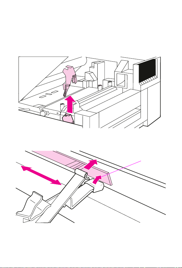
2 Pull the drum lock lever at the left edge of the drum toward you.
Lower the drum until it is horizontal.
CAUTION
Be careful not to contaminate the cleaning tool pad with the oil from
your hands or other contaminants.
3 Locate the laser optics cleaning tool.
1
4 Insert the cleaning tool above the drum with the padded portion
down and towards the glass, and with the cupped portion against
the chrome rod (1). Press the pad on the cleaning tool firmly against
76 Chapter 2 – Cleaning and maintenance
EN
Page 83

the right end of the optics glass. Slide the cleaning tool to the left
side of the printer, and then slide it back to the right. Repeat several
times, then return the cleaning tool to its storage place.
Find the drum cleaning handle located toward the back-right corner
5
of the main drum.
2
Slide the cleaning handle slowly and smoothly to the left end of the
6
drum and completely back to the right home position. (This
EN
Regular maintenance procedures
77
Page 84

procedure should take approximately 3-5 seconds.) Repeat as
necessary.
7 Raise the drum until it locks into place.
Note
The drum corona cleaning handle is only on the new style drum
(C3967A).
CAUTION
Before closing the printer, be sure that the drum corona cleaning
handle and transfer corona cleaning knob are reseated in the
full-right position.
8 Locate the transfer corona cleaning knob located between the
transfer belt and the fuser on the right side of the printer.
CAUTION
Do not touch the transfer be lt surface. Oil fr om your hands and debris
can reduce the life span of the belt and affect print quality.
9 Slide the cleaning knob slowly and smoothly to the left end of the
drum and completely back to the right home position. (This
procedure should take approximately 3-5 seconds.) Repeat as
necessary.
78 Chapter 2 – Cleaning and maintenance
EN
Page 85

When you add toner, clean the toner reservoir area. Add toner only
10
when prompted by a control panel message.
• Push the optional rear feed unit away from the printer. Then open
the toner reservoir cover and use the cover to hold the rear feed
unit away from the printer.
• With the cleaning cloth from the toner collection kit, wipe off any
dust or toner on the area between the individual toner doors.
CAUTION
Do not drop excess toner into the manual feed area. Toner in the
manual feed area can result in manual feed problems.
• Close the toner reservoir cover.
• Return the optional rear feed unit to its upright position against
the back of the printer.
2
EN
Regular maintenance procedures
79
Page 86

Replacement of maintenance units
The printer prompts you from the control panel when it is time to replace
a maintenance unit. The following table lists the approximate time
intervals for replacing maintenance units. For proper printer operation,
use only HP maintenance units. (See Chapter 8 in the service manual.)
Approximate replacement intervals
Unit Printer message Page count** Time period*
Toner TONER OUT [CMYK] ADD [color] 2200 pages 1 to 2 months
Toner collection
box filter
Coating pad,
cleaning roller
Coating roller,
cleaning roller
Black
developer
Color developer 19.2 COLOR DEVEL. USER
Transfer belt 19.5 TRANS BELT USER
Fuser 19.4 FUSER USER
Print drum 19.3 DRUM USER
* This time period assumes you are printing 2,000 pages per month. If your print quantities
differ, adjust the time period accordingly.
** Approximate page count based on 5% coverage of individual toner colors
*** HP Color LaserJet printer
**** HP Color LaserJet 5/5M printer
***** The page count for the drum increments once for every standard black and white or
monochrome page and twice for each multiple color page, legal, tabloid, or A3-size page.
14.5 REPLACE COLLECTION KIT Varies with toner
14.6 REPLACE (CLJ)***
COATING PAD KIT
14.6 Replace Coating Kit
(CLJ5/5M)****
19.1 BLACK DEVEL. USER
MAINTENANCE
MAINTENANCE
MAINTENANCE
MAINTENANCE
MAINTENANCE
usage.
Varies with toner
usage.
Varies with
transparency usage
40,000 pages 15 months
40,000 pages 15 months
60,000 pages 30 months
80,000 pages 40 months
60,000 pages***** 30 months
4 to 6 months
4 to 6 months
4 to 6 months
80 Chapter 2 – Cleaning and maintenance
EN
Page 87
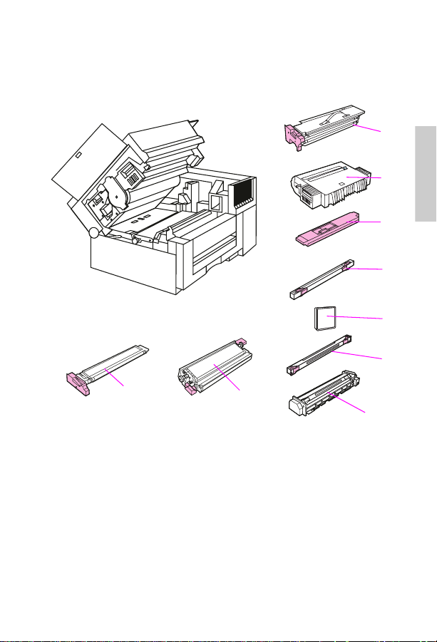
Identifying consumables
The following illustration shows the location of the consumables.
1
2
2
3
4
5
6
9
Consumable locations (CLJ 5/5M)
Color developer
1
Print drum
2
Toner collection
3
box *
* The toner collection box and ozone filter are included in the collection kit.
** The cleaning roller and coating roller are included in the coating kit.
EN
Coating roller**
4
Ozone filter**
5
Cleaning roller
6
8
Fuser
7
Transfer belt
8
Black developer
9
Identifying consumables
7
81
Page 88

Note
Do not install an old-style coating pad kit into a new style fuser. See
the “Supplies compatibility” table on page 83.
Note
All original maintenance items for the HP Color LaserJet printer have
blue handles and tabs that indicate user access or lift points. With the
exception of the toner area, the maintenance items in the HPColor
LaserJet 5/5M printer should have purple handles and tabs.
82 Chapter 2 – Cleaning and maintenance
EN
Page 89

Supplies compatibility
The following supplies for the HPColor LaserJet 5/5M printers are fully
backward-compatible with the HP Color LaserJet printer. However, the
original set of HP Color LaserJet printer supplies should not be used in
HP Color LaserJet 5/5M printers.
HP Color LaserJet and HP Color LaserJet 5/5M
Product
number
Toner Supplies
C3105A Black toner bottle full compatibility • •
C3102A Cyan toner bottle full compatibility • •
C3103A Yellow toner bottle full compatibility • •
C3104A Magenta toner bottle full compatibility • •
C3120A Toner collection kit full compatibility • •
C3106A Coating pad kit compatible with C3911A
C3964A Coating kit* compatible with C3969A
Imaging Units
C3107A Black developer HP Color LaserJet
C3965A Black developer* full compatibility • •
C3108A Color developer HP Color LaserJet
C3966A Color developer* full compatibility • •
C3109A Print drum HP Color LaserJet
C3967A Print drum full compatibility • •
C3110A Transfer assembly HP Color LaserJet
C3968A Transfer assembly* full compatibility • •
C31111
Opt. 110 or
220A
C3969A
Opt 110 or
220
* Products in
Product name Comment Compatible with
fuser unit only
fuser unit only
compatibility ONLY
compatibility ONLY
compatibility ONLY
compatibility ONLY
printers.
Fuser 110 = 110V Opt.
220 = 220V)
Fuser*
(Opt 110 = 110V
Opt 220 = 220V)
bold-faced type
HP Color LaserJet
compatibility ONLY
full compatibility • •
are new supplies introduced with the HP Color LaserJet 5/5M
HP Color
LaserJet
HP Color
LaserJet 5/5M
•
••
•
•
•
•
•
2
EN
Supplies compatibility
83
Page 90

84 Chapter 2 – Cleaning and maintenance
EN
Page 91

Service Mode and
3
Overview
Service Mode allows service personnel to verify and manipulate
internal printer settings and diagnostics. Service Mode should be used
only by authorized service personnel.
diagnostics
EN
Overview
85
Page 92

Service Mode menu
Service Mode is used to test printer functions by issuing commands to
the control board through the control panel. The menu items are:
• Register adjust allows the service engineer to change the factory-
set NVRAM values that control the placement of the image on the
page. In this mode, detailed developer counter information is also
available for troubleshooting toner concentration problems. Enter
this mode as shown in the “Keystroke sequence to enter Service
Mode” on page 87 and “Keystroke sequence to enter Register
Adjust Mode” on page 90. See the “Register adjust addresses”
table on page 91.
input
• Status requests indicates the state of an
Generally, this test applies to sensor requests and switches. These
commands have a control panel indication (or digital value, either
high or low) of the state of the selected input. Inputs that can be
checked with the Service Mode are listed in the “Status and test
address” table on page 94.
• Operation commands control the output of the control board to the
selected component. (Motors and developers are examples of
selectable components.) The command addresses are listed in the
“Status and test address” on page 94. Issuing an output command
starts the function shown in the output list.
Note
Some outputs will stop automatically after a preset time.
• Subtests of the operation command are used for components with
multiple assemblies, functions, or modes. These subtests are
identified by a subtest number. Subtest numbers allow the operator
to select a particular item when several selections are possible. The
subtest numbers are listed in the table on page 97.
to the control board.
86 Chapter 3 – Service Mode and diagnostics
EN
Page 93

Accessing Service Mode
Turn off the printer.
1
Press and hold
2
while turning the printer on. Continue holding the keys until all the
control panel lights are illuminated and the control panel display is
blank.
Press
3
The display will flash
self-test and boot cycle.
[Item]
[Online], [Form Feed]
, and then press
SERVICE MODE
, and
.
[Enter]
. Allow the printer to complete its
(simultaneously)
[Item]
1
1
1
get
5
Keystroke sequence to enter Service Mode
EN
2
3
Service Mode menu
3
4
87
Page 94

A
Service Mode flow chart
B
88 Chapter 3 – Service Mode and diagnostics
EN
Page 95

Register Adjust Mode
The Register Adjust Mode allows the service engineer access to the
NVRAM address. Changing the value of this address allows the paper
registration to be adjusted. This mode also provides detailed developer
counter information that is needed for troubleshooting toner
concentration.
Note
This mode does not affect the operation of solenoids or sensors. Use
the Status and T est Mode on page 92 to monitor and test the solenoids
and sensors.
Accessing the Register Adjust Mode
Enter Service Mode as described in the previous section.
1
Repeatedly press
2
Press
3
Press
4
Use
5
digits until the desired address is displayed.
Press
6
Use
7
desired value.
Press
8
If the address is invalid or appears as read-only, press
9
select a new address.
Power cycle the printer to continue normal operation.
10
to display
[Item]
to activate the Register Adjust Mode.
[Enter]
[Online], [Form Feed]
to obtain the address value.
[Enter]
[Form Feed]
to save the new value.
[Enter]
to display
[Menu]
REGISTER ADJUST
, and
and
[Reset]
ENGINE SERVICE
.
to increment the address
[Reset]
to change the address value to the
.
[Enter]
to
3
EN
Register Adjust Mode
89
Page 96
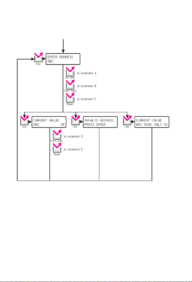
A
Keystroke sequence to enter Register Adjust Mode
90 Chapter 3 – Service Mode and diagnostics
EN
Page 97

Register Adjust Mode addresses
This table lists the accessible addresses in the control NVRAM.
Register adjust addresses
Address Initial
* These are read-only values.
** This register can be reset to 00 to clear 50.X Fuser errors without waiting for the fuser error
*** Default values
value
28 00* Black developing unit counter (10s & 1s digit). Range = 00-99
29 00* Black developing unit counter (1000s & 100s digit). Range= 00-99
30 00* Black developing unit counter (100,000s & 10,000s digit. Range=00-99
31 00* Yellow developing unit counter (10s & 1s digit). Range = 00-99
32 00* Yellow developing unit counter (1000s & 100s digit). Range= 00-99
33 00* Yellow developing unit counter (100000s & 10000s digit). Range = 00-99
34 00* Magenta developing unit counter (10s & 1s digit). Range = 00-99
35 00* Magenta developing unit counter (1000s & 100s digit). Range = 00-99
36 00* Magenta developing unit counter (100000s & 10000s digit).
37 00* Cyan developing unit counter (10s & 1s digit). Range = 00-99
38 00* Cyan developing unit counter (1000s & 100s digit). Range = 00-99
39 00* Cyan developing unit counter (100000s & 10000s digit). Range = 00-99
47 00** Fuser error code (00 - 01)
74 48*** Leading edge margin adjustment for RFU auto-feed. Range = 35-65
75 43*** Side margin (start of scan) adjustment for RFU auto-feed.
76 48*** Leading edge margin adjustment for manual feed. Range = 35-65
77 43*** Side margin (start of scan) adjustment for manual feed.Range = 01-99
78 48*** Leading edge margin adjustment for main tray. Range = 35-65
79 43*** Side margin (start of scan) adjustment for main tray. Range = 01-99
timeout.
Range = 00-99
Range = 01-99
Function
3
EN
Register Adjust Mode
91
Page 98

Status and Test Mode
B
Selecting the status and test addresses
The Status and Test Mode allows the service engineer access to
individual printer components. Access the Status and Test Mode from
the Service Mode menu. Enter Service Mode as shown on page 87 and
then complete the following steps:
1 Repeatedly press [Menu] to display
selection is
2 Press [Item] to select the Status and Test Mode.
3 Press [Enter] to activate the Status and Test Mode.
4 Use [Online] and [Form Feed] to increment the address digits until
the desired address is displayed.
REGISTER ADJUST
ENGINE SERVICE
.
. The first
92 Chapter 3 – Service Mode and diagnostics
EN
Page 99

Press
5
If necessary, input the subtest number by pressing
6
desired subtest number is displayed.
When
7
The number on the right is the status value for the address that was
entered in step 5. This value is updated once every second.
Press
8
Press
9
for the address entered in step 5.
Press
10
to activate the displayed address.
[Enter]
ONLINE TO START
to cancel the Status Mode.
[Reset]
to activate the Test Mode. The printer starts the test
[Online]
to cancel the Test Mode.
[Reset]
is displayed, the printer is in Status Mode.
[Online]
until the
Status and test addresses
The addresses listed in the “Status and test address” table on page 94
select the function shown in the status column or enable the test listed
in the test column. Status shows the state of the switch, sensor , or other
component that the control board responds to. Subtest numbers also
apply to some of the tests (such as developer tests). Subtest numbers
select a particular subtest (such as black developer) when more than
one function is possible. Subtest numbers are listed separately on page
97.
Note
Status and test codes are not coded together and therefore may not
match. Many status outputs and test functions share an address. For
instance, when address 20 is entered, the display shows the status
of the registration sensor. Pressing
solenoid.
EN
activates the paper-feed
[Online]
Status and Test Mode
93
3
Page 100

Status and test address
Address Status Test
01 Toner leve l detection. Shows logic of the
08 Toner concentration sensor signal for the
10 Paper empty (main tray). Indicates the state
13 Rear input empty sensor (RFU).
14 Paper empty sensor (RFU manual feed).
15 Paper size signal (tray). Indicates the
16 Paper size signal (RFU). Indicates the state
19* Unlocks all toner hoppers
20* Registration sensor signal. (PS7) Indicates
21 Rear feed unit paper-in-path sensor. Detects
22 Paper exit sensor signal, indicates the logic
25* Turns on the registration solenoid
* This address has an automatic shut-off to protect the component from extended use.
toner level detect sensor for the selected
color.
1=toner present, 0=toner empty
selected color. The initial value is 63.
Starting the test displays the current
concentration offset value.
of the paper-out sensor (PS8).
1=paper present, 0=paper empty
1=paper empty, 0=paper present
1=paper not present, 0=paper present
detected tray size: lgl=0, ledger (tabloid)=1,
Ltr=2, Exec=4, A3=5, A4=6, No tray=7
of the RFU paper size sensor: 1=A4,
2=exec, 3=ltr.
the state of the registration sensor.
1=paper detected, 0=paper not detected
media in the RFU.
states of the paper exit sensor. (PS1)
1=paper not detected, 0=paper detected
Rotates the developing unit for the
selected color. You should hear the
developer rotate when this test is
run.
Turns on the paper tray solenoid
(SL1)
(SL2)
94 Chapter 3 – Service Mode and diagnostics
EN
 Loading...