

Page 1
Page 2

Page 3

HP LaserJet 3100/3150 Product
Service Manual
Page 4

Copyright Information
© 2002 Hewlett-Packard
Company
All Rights Reserved.
Reproduction, adaptation, or
translation without prior written
permission is prohibited except
as allowed under copyright
laws.
Part Number: C4256-90954
Second Edition, February 2002
Warranty
The information contained in
this document is subject to
change without notice.
Hewlett-Packard makes no
warranty of any kind with
respect to this information.
HEWLETT-PACKARD
SPECIFICALLY DISCLAIMS
THE IMPLIED WARRANTY OF
MERCHANTABILITY AND
FITNESS FOR A PARTICULAR
PURPOSE
Hewlett-Packard shall not be
liable for any dire ct, indirect,
incidental, consequential, or
other damage alleged in
connection with the furnishing or
use of this information.
NOTICE TO U.S.
GOVERNMENT USERS:
RESTRICTED RIGHTS
COMMERCIAL COMPUTER
SOFTWARE: “Use, duplication,
or disclosure by the
Government is subject to
restrictions as set forth in
subparagraph (c)(1)(ii) of the
Rights in Technical Data Clause
at DFARS 52.227-7013.”
Material scanned by this
product may be protected by
governmental laws and other
regulations, such as copyright
laws. The customer is solely
responsible for complying with
all such laws and regulations.
This product ma y be ser viced
only in the country for which it
was designed to be used.
Trademark Credits
JetSuite Pro Desktop for
Hewlett-Packard is a trademark
of JetFax, Inc.
Microsoft, Windows, and
MS-DOS are U.S. registered
trademarks of Microsoft
Corporation.
Iris is a registered trademark of
the Caere Corporation.
E
NERGY STAR is a U.S.
registered service mark of the
United States Environmental
Protection Agency.
CompuServe is a trademark of
CompuServe, Inc.
All other products mentioned
herein may be trademarks of
their respective companies.
Hewlett-Packard Company
11311 Chinden Boulevard
Boise, Idaho 83714 U.S.A.
Page 5

Contents
1 Product I nformation
Chapter contents. . . . . . . . . . . . . . . . . . . . . . . . . . . . . . . . . . . . . . . 13
Introduction . . . . . . . . . . . . . . . . . . . . . . . . . . . . . . . . . . . . . . . . . . . 14
Product features . . . . . . . . . . . . . . . . . . . . . . . . . . . . . . . . . . . . . . . 15
Product specifications . . . . . . . . . . . . . . . . . . . . . . . . . . . . . . . . . . . 16
Model and serial numbers. . . . . . . . . . . . . . . . . . . . . . . . . . . . . . . . 18
Product overview. . . . . . . . . . . . . . . . . . . . . . . . . . . . . . . . . . . . . . . 19
Regulatory information . . . . . . . . . . . . . . . . . . . . . . . . . . . . . . . . . . 23
Safety . . . . . . . . . . . . . . . . . . . . . . . . . . . . . . . . . . . . . . . . . . . . 23
Laser statement for Finland . . . . . . . . . . . . . . . . . . . . . . . . . . . 24
FCC regulations . . . . . . . . . . . . . . . . . . . . . . . . . . . . . . . . . . . . 25
Telephone consumer protection act (U.S.). . . . . . . . . . . . . . . . 27
IC CS-03 requirements. . . . . . . . . . . . . . . . . . . . . . . . . . . . . . . 28
Declaration of conformity . . . . . . . . . . . . . . . . . . . . . . . . . . . . . 29
Canadian DOC regulations. . . . . . . . . . . . . . . . . . . . . . . . . . . . 30
Environmental product stewardship program . . . . . . . . . . . . . . 30
Material safety data sheet. . . . . . . . . . . . . . . . . . . . . . . . . . . . . 34
2 Installation and operation
EN
Chapter contents. . . . . . . . . . . . . . . . . . . . . . . . . . . . . . . . . . . . . . . 35
Operating environment . . . . . . . . . . . . . . . . . . . . . . . . . . . . . . . . . . 36
Media requirements. . . . . . . . . . . . . . . . . . . . . . . . . . . . . . . . . . . . . 37
Toner cartridge information. . . . . . . . . . . . . . . . . . . . . . . . . . . . . . . 38
Storage conditions . . . . . . . . . . . . . . . . . . . . . . . . . . . . . . . . . . 38
Storing opened toner cartridges . . . . . . . . . . . . . . . . . . . . . . . . 38
Toner Recycling . . . . . . . . . . . . . . . . . . . . . . . . . . . . . . . . . . . . 38
Control panel. . . . . . . . . . . . . . . . . . . . . . . . . . . . . . . . . . . . . . . . . . 39
Control panel messages. . . . . . . . . . . . . . . . . . . . . . . . . . . . . . 40
Menu tree . . . . . . . . . . . . . . . . . . . . . . . . . . . . . . . . . . . . . . . . . 52
3 Ma intena nce
Chapter contents. . . . . . . . . . . . . . . . . . . . . . . . . . . . . . . . . . . . . . . 55
Life expectancies of consumables . . . . . . . . . . . . . . . . . . . . . . . . . 56
Cleaning and maintaining the equipment . . . . . . . . . . . . . . . . . . . . 57
Cleaning the document scanner path . . . . . . . . . . . . . . . . . . . . . . . 58
Cleaning the print path . . . . . . . . . . . . . . . . . . . . . . . . . . . . . . . . . . 60
Using a cleaning page. . . . . . . . . . . . . . . . . . . . . . . . . . . . . . . . . . . 63
Contents
3
Page 6

4 Functional overview
Chapter contents. . . . . . . . . . . . . . . . . . . . . . . . . . . . . . . . . . . . . . . 65
Basic functions . . . . . . . . . . . . . . . . . . . . . . . . . . . . . . . . . . . . . . . . 66
Printer functions . . . . . . . . . . . . . . . . . . . . . . . . . . . . . . . . . . . . . . . 67
ECU/power system . . . . . . . . . . . . . . . . . . . . . . . . . . . . . . . . . . . . . 68
Print engine control system . . . . . . . . . . . . . . . . . . . . . . . . . . . 69
Power system (on ECU) . . . . . . . . . . . . . . . . . . . . . . . . . . . . . . 70
Formatter system . . . . . . . . . . . . . . . . . . . . . . . . . . . . . . . . . . . . . . 72
Central processing unit. . . . . . . . . . . . . . . . . . . . . . . . . . . . . . . 72
Memory. . . . . . . . . . . . . . . . . . . . . . . . . . . . . . . . . . . . . . . . . . . 72
Parallel interface. . . . . . . . . . . . . . . . . . . . . . . . . . . . . . . . . . . . 73
Control panel. . . . . . . . . . . . . . . . . . . . . . . . . . . . . . . . . . . . . . . 73
Draft mode . . . . . . . . . . . . . . . . . . . . . . . . . . . . . . . . . . . . . . . . 73
Image formation system . . . . . . . . . . . . . . . . . . . . . . . . . . . . . . . . . 74
Toner cartridge . . . . . . . . . . . . . . . . . . . . . . . . . . . . . . . . . . . . . 74
Step 1: Primary charging . . . . . . . . . . . . . . . . . . . . . . . . . . . . . 75
Step 2: Scanning exposure. . . . . . . . . . . . . . . . . . . . . . . . . . . . 75
Step 3: Developing . . . . . . . . . . . . . . . . . . . . . . . . . . . . . . . . . . 75
Step 4: Transferring . . . . . . . . . . . . . . . . . . . . . . . . . . . . . . . . . 76
Step 5: Separating . . . . . . . . . . . . . . . . . . . . . . . . . . . . . . . . . . 76
Step 6: Drum cleaning . . . . . . . . . . . . . . . . . . . . . . . . . . . . . . . 76
Fixing stage. . . . . . . . . . . . . . . . . . . . . . . . . . . . . . . . . . . . . . . . 76
Printer feed system . . . . . . . . . . . . . . . . . . . . . . . . . . . . . . . . . . . . . 77
Paper jam detection . . . . . . . . . . . . . . . . . . . . . . . . . . . . . . . . . 79
Solenoid, photosensors, and switches . . . . . . . . . . . . . . . . . . . 80
Document scanner system . . . . . . . . . . . . . . . . . . . . . . . . . . . . . . . 81
Basic sequence of operation (formatter-to-printer) . . . . . . . . . . . . . 83
4 Contents
5 Removal and replacement
Chapter contents. . . . . . . . . . . . . . . . . . . . . . . . . . . . . . . . . . . . . . . 85
Removal and replacement strategy. . . . . . . . . . . . . . . . . . . . . . . . . 86
Required tools. . . . . . . . . . . . . . . . . . . . . . . . . . . . . . . . . . . . . . . . . 87
Covers. . . . . . . . . . . . . . . . . . . . . . . . . . . . . . . . . . . . . . . . . . . . . . . 88
Back cover . . . . . . . . . . . . . . . . . . . . . . . . . . . . . . . . . . . . . . . . 88
Right side cover . . . . . . . . . . . . . . . . . . . . . . . . . . . . . . . . . . . . 90
Left side cover. . . . . . . . . . . . . . . . . . . . . . . . . . . . . . . . . . . . . . 91
Left front cover . . . . . . . . . . . . . . . . . . . . . . . . . . . . . . . . . . . . . 92
Top cover . . . . . . . . . . . . . . . . . . . . . . . . . . . . . . . . . . . . . . . . . 93
RFI shield . . . . . . . . . . . . . . . . . . . . . . . . . . . . . . . . . . . . . . . . . 94
Document scanner assemblies. . . . . . . . . . . . . . . . . . . . . . . . . . . . 95
Printer door. . . . . . . . . . . . . . . . . . . . . . . . . . . . . . . . . . . . . . . . 95
Document release door. . . . . . . . . . . . . . . . . . . . . . . . . . . . . . . 98
Upper guide assembly . . . . . . . . . . . . . . . . . . . . . . . . . . . . . . 100
Contact image sensor. . . . . . . . . . . . . . . . . . . . . . . . . . . . . . . 102
Document scanner assembly/motor . . . . . . . . . . . . . . . . . . . . 104
Document scanner pickup roller . . . . . . . . . . . . . . . . . . . . . . . 106
EN
Page 7

Internal assemblies . . . . . . . . . . . . . . . . . . . . . . . . . . . . . . . . . . . . 107
LIU board . . . . . . . . . . . . . . . . . . . . . . . . . . . . . . . . . . . . . . . . 107
Formatter board . . . . . . . . . . . . . . . . . . . . . . . . . . . . . . . . . . . 108
Metal side plate. . . . . . . . . . . . . . . . . . . . . . . . . . . . . . . . . . . . 110
Exit roller. . . . . . . . . . . . . . . . . . . . . . . . . . . . . . . . . . . . . . . . . 111
Delivery assembly. . . . . . . . . . . . . . . . . . . . . . . . . . . . . . . . . . 112
Fuser pressure plate. . . . . . . . . . . . . . . . . . . . . . . . . . . . . . . . 114
Front casing . . . . . . . . . . . . . . . . . . . . . . . . . . . . . . . . . . . . . . 116
Heating element . . . . . . . . . . . . . . . . . . . . . . . . . . . . . . . . . . . 117
Pressure roller. . . . . . . . . . . . . . . . . . . . . . . . . . . . . . . . . . . . . 119
Face-up/face-down lever . . . . . . . . . . . . . . . . . . . . . . . . . . . . 120
Fuser exit roller assembly. . . . . . . . . . . . . . . . . . . . . . . . . . . . 121
Paper exit sensor flag. . . . . . . . . . . . . . . . . . . . . . . . . . . . . . . 122
Laser/scanner assembly. . . . . . . . . . . . . . . . . . . . . . . . . . . . . 123
Solenoid . . . . . . . . . . . . . . . . . . . . . . . . . . . . . . . . . . . . . . . . . 124
Pickup roller assembly . . . . . . . . . . . . . . . . . . . . . . . . . . . . . . 126
Paper feed frame . . . . . . . . . . . . . . . . . . . . . . . . . . . . . . . . . . 129
Transfer roller guide and transfer roller. . . . . . . . . . . . . . . . . . 132
Kick plate . . . . . . . . . . . . . . . . . . . . . . . . . . . . . . . . . . . . . . . . 133
Separation pad . . . . . . . . . . . . . . . . . . . . . . . . . . . . . . . . . . . . 135
Subpads . . . . . . . . . . . . . . . . . . . . . . . . . . . . . . . . . . . . . . . . 136
Feed assembly . . . . . . . . . . . . . . . . . . . . . . . . . . . . . . . . . . . . 137
Bottom assemblies . . . . . . . . . . . . . . . . . . . . . . . . . . . . . . . . . . . . 140
Cable guide. . . . . . . . . . . . . . . . . . . . . . . . . . . . . . . . . . . . . . . 140
Main Motor . . . . . . . . . . . . . . . . . . . . . . . . . . . . . . . . . . . . . . . 141
ECU . . . . . . . . . . . . . . . . . . . . . . . . . . . . . . . . . . . . . . . . . . . . 142
Feet. . . . . . . . . . . . . . . . . . . . . . . . . . . . . . . . . . . . . . . . . . . . . 146
EN
6 Trouble shooting
Chapter contents. . . . . . . . . . . . . . . . . . . . . . . . . . . . . . . . . . . . . . 147
Basic troubleshooting . . . . . . . . . . . . . . . . . . . . . . . . . . . . . . . . . . 148
Error messages. . . . . . . . . . . . . . . . . . . . . . . . . . . . . . . . . . . . . . . 152
Image formation troubleshooting. . . . . . . . . . . . . . . . . . . . . . . . . . 157
Check the toner cartridge . . . . . . . . . . . . . . . . . . . . . . . . . . . . 157
Solving image quality problems . . . . . . . . . . . . . . . . . . . . . . . 158
Solving paper feed problems. . . . . . . . . . . . . . . . . . . . . . . . . . . . . 165
Solving general software problems. . . . . . . . . . . . . . . . . . . . . . . . 169
Functional checks . . . . . . . . . . . . . . . . . . . . . . . . . . . . . . . . . . . . . 173
Simple hardware test . . . . . . . . . . . . . . . . . . . . . . . . . . . . . . . 173
Engine test . . . . . . . . . . . . . . . . . . . . . . . . . . . . . . . . . . . . . . . 174
Internal reports . . . . . . . . . . . . . . . . . . . . . . . . . . . . . . . . . . . . 175
Printing all reports at once . . . . . . . . . . . . . . . . . . . . . . . . . . . 176
Half-self test functional check. . . . . . . . . . . . . . . . . . . . . . . . . 177
Drum rotation functional check . . . . . . . . . . . . . . . . . . . . . . . . 178
Heating element check . . . . . . . . . . . . . . . . . . . . . . . . . . . . . . 179
High-voltage power supply check. . . . . . . . . . . . . . . . . . . . . . 180
Contents
5
Page 8

Paper curl . . . . . . . . . . . . . . . . . . . . . . . . . . . . . . . . . . . . . . . . 181
Paper path check . . . . . . . . . . . . . . . . . . . . . . . . . . . . . . . . . . 182
Troubleshooting tools . . . . . . . . . . . . . . . . . . . . . . . . . . . . . . . . . . 183
Paper path and components. . . . . . . . . . . . . . . . . . . . . . . . . . 183
Document path and components . . . . . . . . . . . . . . . . . . . . . . 184
Repetitive image defect ruler . . . . . . . . . . . . . . . . . . . . . . . . . 185
Document scanner recalibration. . . . . . . . . . . . . . . . . . . . . . . 186
Main wiring . . . . . . . . . . . . . . . . . . . . . . . . . . . . . . . . . . . . . . . 188
Service menus. . . . . . . . . . . . . . . . . . . . . . . . . . . . . . . . . . . . . . . . 190
Control panel service menu . . . . . . . . . . . . . . . . . . . . . . . . . . 190
Extended service menu . . . . . . . . . . . . . . . . . . . . . . . . . . . . . 191
Softswitches . . . . . . . . . . . . . . . . . . . . . . . . . . . . . . . . . . . . . . . . . 197
To change the country code softswitch. . . . . . . . . . . . . . . . . . 197
Firmware and software downloads . . . . . . . . . . . . . . . . . . . . . . . . 199
Hardware, software, and firmware compatibility. . . . . . . . . . . 200
Fax trace report. . . . . . . . . . . . . . . . . . . . . . . . . . . . . . . . . . . . . . . 201
7 Parts and diagrams
Chapter contents. . . . . . . . . . . . . . . . . . . . . . . . . . . . . . . . . . . . . . 209
How to use the parts lists and diagrams . . . . . . . . . . . . . . . . . . . . 210
Ordering parts. . . . . . . . . . . . . . . . . . . . . . . . . . . . . . . . . . . . . 210
Consumables and accessories . . . . . . . . . . . . . . . . . . . . . . . . . . . 211
Ordering consumables . . . . . . . . . . . . . . . . . . . . . . . . . . . . . . 213
Common hardware . . . . . . . . . . . . . . . . . . . . . . . . . . . . . . . . . . . . 214
Alphabetical parts list . . . . . . . . . . . . . . . . . . . . . . . . . . . . . . . . . . 242
Numerical parts list . . . . . . . . . . . . . . . . . . . . . . . . . . . . . . . . . . . . 249
6 Contents
Appendix A Additional use r notes
Document scanner separation pad replacement. . . . . . . . . . . . . . 255
When to replace the document scanner separation pad . . . . 255
How to replace the document scanner separation pad. . . . . . 256
Index
EN
Page 9

Figures
Figure 1. Model and serial number label . . . . . . . . . . . . . . . . . 18
Figure 2. Document scanner path . . . . . . . . . . . . . . . . . . . . . . 19
Figure 3. Printer path (1 of 2) . . . . . . . . . . . . . . . . . . . . . . . . . . 20
Figure 4. Printer path (2 of 2) . . . . . . . . . . . . . . . . . . . . . . . . . . 21
Figure 5. Rear view . . . . . . . . . . . . . . . . . . . . . . . . . . . . . . . . . . 22
Figure 6. Control panel layout . . . . . . . . . . . . . . . . . . . . . . . . . . 39
Figure 7. Basic configuration . . . . . . . . . . . . . . . . . . . . . . . . . . 66
Figure 8. Printer unit functional block diagram . . . . . . . . . . . . . 67
Figure 9. ECU loads . . . . . . . . . . . . . . . . . . . . . . . . . . . . . . . . . 68
Figure 10. High-voltage power supply circuit . . . . . . . . . . . . . . . 71
Figure 11. Image formation block diagram . . . . . . . . . . . . . . . . . 74
Figure 12. Simplified paper path . . . . . . . . . . . . . . . . . . . . . . . . . 78
Figure 13. Solenoid, photosensors, and switches . . . . . . . . . . . 80
Figure 14. Simplified document path . . . . . . . . . . . . . . . . . . . . . 82
Figure 15. General timing diagram . . . . . . . . . . . . . . . . . . . . . . . 84
Figure 16. Back cover removal (1 of 2) . . . . . . . . . . . . . . . . . . . . 88
Figure 17. Back cover removal (2 of 2) . . . . . . . . . . . . . . . . . . . . 89
Figure 18. Right side cover removal . . . . . . . . . . . . . . . . . . . . . . 90
Figure 19. Left side cover removal . . . . . . . . . . . . . . . . . . . . . . . 91
Figure 20. Left front cover removal . . . . . . . . . . . . . . . . . . . . . . . 92
Figure 21. Top cover removal . . . . . . . . . . . . . . . . . . . . . . . . . . . 93
Figure 22. RFI shield removal . . . . . . . . . . . . . . . . . . . . . . . . . . . 94
Figure 23. Printer door removal (1 of 3) . . . . . . . . . . . . . . . . . . . 95
Figure 24. Printer door removal (2 of 3) . . . . . . . . . . . . . . . . . . . 96
Figure 25. Printer door removal (3 of 3) . . . . . . . . . . . . . . . . . . . 97
Figure 26. Document release door removal (1 of 2) . . . . . . . . . . 98
Figure 27. Document release door removal (2 of 2) . . . . . . . . . . 99
Figure 28. Upper guide assembly removal (1 of 2) . . . . . . . . . . 100
Figure 29. Upper guide assembly removal (2 of 2) . . . . . . . . . . 101
Figure 30. Contact image sensor removal (1 of 2) . . . . . . . . . . 102
Figure 31. Contact image sensor removal (2 of 2) . . . . . . . . . . 103
Figure 32. Document scanner motor removal (1 of 2) . . . . . . . 104
Figure 33. Document scanner motor removal (2 of 2) . . . . . . . 105
Figure 34. Document scanner pickup roller removal . . . . . . . . 106
Figure 35. LIU board removal . . . . . . . . . . . . . . . . . . . . . . . . . . 107
Figure 36. Formatter board removal (1 of 2) . . . . . . . . . . . . . . . 108
Figure 37. Formatter board removal (2 of 2) . . . . . . . . . . . . . . . 109
Figure 38. Metal side plate removal . . . . . . . . . . . . . . . . . . . . . 110
Figure 39. Exit roller removal . . . . . . . . . . . . . . . . . . . . . . . . . . 111
Figure 40. Delivery assembly removal (1 of 2) . . . . . . . . . . . . . 112
Figure 41. Delivery assembly removal (2 of 2) . . . . . . . . . . . . . 113
EN
Contents-7
Page 10

Figure 42. Fuser pressure plate removal . . . . . . . . . . . . . . . . . 114
Figure 43. Fuser pressure plate replacement . . . . . . . . . . . . . . 115
Figure 44. Front casing removal . . . . . . . . . . . . . . . . . . . . . . . . 116
Figure 45. Heating element removal (1 of 2) . . . . . . . . . . . . . . 117
Figure 46. Heating element removal (2 of 2) . . . . . . . . . . . . . . 118
Figure 47. Pressure roller guide removal . . . . . . . . . . . . . . . . . 119
Figure 48. Face-up/face-down lever replacement . . . . . . . . . . 120
Figure 49. Fuser exit roller assembly removal . . . . . . . . . . . . . 121
Figure 50. Paper exit sensor flag replacement . . . . . . . . . . . . . 122
Figure 51. Laser/scanner assembly removal . . . . . . . . . . . . . . 123
Figure 52. Solenoid removal (1 of 2) . . . . . . . . . . . . . . . . . . . . 124
Figure 53. Solenoid removal (2 of 2) . . . . . . . . . . . . . . . . . . . . 125
Figure 54. Pickup roller assembly removal (1 of 2) . . . . . . . . . 126
Figure 55. Pickup roller assembly removal (2 of 2) . . . . . . . . . 127
Figure 56. Paper pickup roller assembly replacement . . . . . . . 128
Figure 57. Paper feed frame removal (1 of 3) . . . . . . . . . . . . . . 129
Figure 58. Paper feed frame removal (2 of 3) . . . . . . . . . . . . . . 130
Figure 59. Paper feed frame removal (3 of 3) . . . . . . . . . . . . . . 131
Figure 60. Transfer roller guide and transfer roller removal . . . 132
Figure 61. Kick plate removal . . . . . . . . . . . . . . . . . . . . . . . . . . 133
Figure 62. Kick plate spring replacement . . . . . . . . . . . . . . . . . 134
Figure 63. Separation pad removal . . . . . . . . . . . . . . . . . . . . . 135
Figure 64. Subpad removal . . . . . . . . . . . . . . . . . . . . . . . . . . . 136
Figure 65. Feed assembly removal (1 of 3) . . . . . . . . . . . . . . . 137
Figure 66. Feed assembly removal (2 of 3) . . . . . . . . . . . . . . . 138
Figure 67. Feed assembly removal (3 of 3) . . . . . . . . . . . . . . . 139
Figure 68. Cable guide removal . . . . . . . . . . . . . . . . . . . . . . . . 140
Figure 69. Motor removal . . . . . . . . . . . . . . . . . . . . . . . . . . . . . 141
Figure 70. ECU removal (1 of 4) . . . . . . . . . . . . . . . . . . . . . . . . 142
Figure 71. ECU removal (2 of 4) . . . . . . . . . . . . . . . . . . . . . . . . 143
Figure 72. ECU removal (3 of 4) . . . . . . . . . . . . . . . . . . . . . . . . 144
Figure 73. ECU removal (4 of 4) . . . . . . . . . . . . . . . . . . . . . . . . 145
Figure 74. Feet removal . . . . . . . . . . . . . . . . . . . . . . . . . . . . . . 146
Figure 75. Engine test switch location . . . . . . . . . . . . . . . . . . . 174
Figure 76. Toner cartridge high-voltage connection points . . . . 180
Figure 77. High-voltage connector assembly . . . . . . . . . . . . . . 181
Figure 78. Overriding SW101 . . . . . . . . . . . . . . . . . . . . . . . . . . 182
Figure 79. Paper path and components . . . . . . . . . . . . . . . . . . 183
Figure 80. Document path and components . . . . . . . . . . . . . . . 184
Figure 81. Repetitive image defect ruler . . . . . . . . . . . . . . . . . . 185
Figure 82. General circuit diagram (1 of 2) . . . . . . . . . . . . . . . . 188
Figure 83. General circuit diagram (2 of 2) . . . . . . . . . . . . . . . . 189
Figure 84. Example of a successfully sent fax . . . . . . . . . . . . . 206
Figure 85. Example of a successfully received fax . . . . . . . . . . 207
Figure 86. Major assembly locations . . . . . . . . . . . . . . . . . . . . 215
Figure 87. Supports . . . . . . . . . . . . . . . . . . . . . . . . . . . . . . . . . 216
Figure 88. External covers and panels . . . . . . . . . . . . . . . . . . . 218
8
EN
Page 11

Figure 89. Printer door (1 of 2) . . . . . . . . . . . . . . . . . . . . . . . . . 220
Figure 90. Printer door (2 of 2) . . . . . . . . . . . . . . . . . . . . . . . . . 222
Figure 91. Document scanner assembly . . . . . . . . . . . . . . . . . 224
Figure 92. Internal components (1 of 3) . . . . . . . . . . . . . . . . . . 226
Figure 93. Internal components (2 of 3) . . . . . . . . . . . . . . . . . . 228
Figure 94. Internal components (3 of 3) . . . . . . . . . . . . . . . . . . 230
Figure 95. Electrical components assembly . . . . . . . . . . . . . . . 232
Figure 96. Paper pickup assembly . . . . . . . . . . . . . . . . . . . . . . 234
Figure 97. Feed assembly . . . . . . . . . . . . . . . . . . . . . . . . . . . . 236
Figure 98. Separation guide assembly . . . . . . . . . . . . . . . . . . . 238
Figure 99. Delivery assembly . . . . . . . . . . . . . . . . . . . . . . . . . . 240
Figure 100. Document scanner separation pad replacement . . . 256
EN
9
Page 12

10
EN
Page 13

Tables
Table 1. Product features . . . . . . . . . . . . . . . . . . . . . . . . . . . . . 15
Table 2. Physical specifications . . . . . . . . . . . . . . . . . . . . . . . . 16
Table 3. Performance specifications . . . . . . . . . . . . . . . . . . . . 16
Table 4. Power specifications. . . . . . . . . . . . . . . . . . . . . . . . . . 17
Table 5. Operating acoustical emissions specifications . . . . . . 17
Table 6. Skew specifications . . . . . . . . . . . . . . . . . . . . . . . . . . 17
Table 7. Environmental requirements. . . . . . . . . . . . . . . . . . . . 36
Table 8. Media requirements . . . . . . . . . . . . . . . . . . . . . . . . . . 37
Table 9. Control panel messages. . . . . . . . . . . . . . . . . . . . . . . 40
Table 10. Life expectancies of consumables . . . . . . . . . . . . . . . 56
Table 11. DC power distribution . . . . . . . . . . . . . . . . . . . . . . . . . 70
Table 12. Timing. . . . . . . . . . . . . . . . . . . . . . . . . . . . . . . . . . . . . 83
Table 13. Control panel service menu . . . . . . . . . . . . . . . . . . . 190
Table 14. Extended service menu tree. . . . . . . . . . . . . . . . . . . 192
Table 15. Extended service mode self-test failures . . . . . . . . . 193
Table 16. Extended service mode tests . . . . . . . . . . . . . . . . . . 194
Table 17. Extended service mode reports . . . . . . . . . . . . . . . . 195
Table 18. Country code softswitch sequences. . . . . . . . . . . . . 198
Table 19. Hardware, software, and firmware compatibility. . . . 200
Table 20. Fax phase sequence . . . . . . . . . . . . . . . . . . . . . . . . 202
Table 21. Appropriate responses . . . . . . . . . . . . . . . . . . . . . . . 203
Table 22. Fax abbreviations . . . . . . . . . . . . . . . . . . . . . . . . . . . 204
Table 23. Consumables and accessories. . . . . . . . . . . . . . . . . 211
Table 24. Common fasteners . . . . . . . . . . . . . . . . . . . . . . . . . . 214
Table 25. Supports . . . . . . . . . . . . . . . . . . . . . . . . . . . . . . . . . . 217
Table 26. External covers and panels . . . . . . . . . . . . . . . . . . . 219
Table 27. Printer door (1 of 2) . . . . . . . . . . . . . . . . . . . . . . . . . 221
Table 28. Printer door (2 of 2) . . . . . . . . . . . . . . . . . . . . . . . . . 223
Table 29. Document scanner assembly . . . . . . . . . . . . . . . . . . 225
Table 30. Internal components (1 of 3). . . . . . . . . . . . . . . . . . . 227
Table 31. Internal components (2 of 3). . . . . . . . . . . . . . . . . . . 229
Table 32. Internal components (3 of 3). . . . . . . . . . . . . . . . . . . 231
Table 33. Electrical components assembly . . . . . . . . . . . . . . . 233
Table 34. Paper pickup assembly . . . . . . . . . . . . . . . . . . . . . . 235
Table 35. Feeder assembly . . . . . . . . . . . . . . . . . . . . . . . . . . . 237
Table 36. Separation guide assembly . . . . . . . . . . . . . . . . . . . 239
Table 37. Delivery assembly . . . . . . . . . . . . . . . . . . . . . . . . . . 241
Table 38. Alphabetical parts list . . . . . . . . . . . . . . . . . . . . . . . . 242
Table 39. Numerical parts list. . . . . . . . . . . . . . . . . . . . . . . . . . 249
EN
Contents-11
Page 14

12
EN
Page 15

1
Product Information
C hapter conte nts
Introduction . . . . . . . . . . . . . . . . . . . . . . . . . . . . . . . . . . . . . . . . . . . 14
Product features . . . . . . . . . . . . . . . . . . . . . . . . . . . . . . . . . . . . . . . 15
Product specifications . . . . . . . . . . . . . . . . . . . . . . . . . . . . . . . . . . . 16
Model and serial numbers. . . . . . . . . . . . . . . . . . . . . . . . . . . . . . . . 18
Product overview. . . . . . . . . . . . . . . . . . . . . . . . . . . . . . . . . . . . . . . 19
Regulatory information . . . . . . . . . . . . . . . . . . . . . . . . . . . . . . . . . . 23
EN
Chapter contents 13
Page 16

Introduction
The HP LaserJet 3100/3150 product is a powerful business tool with
the capabilities of a full range of office equipment. With the HP
LaserJet 3100/3150 product, you can:
● Print—Easily print documents with the laser quality you have
● Fax—Use the HP LaserJet 3100/3150 product as a standalone
● Copy—Make superior laser-quality copies. You can make up to
● Scan—Scan important documents to create electronic files.
● Use Software—Use the software to print, fax, copy, or scan. Also
come to expect from an HP LaserJet printer.
fax machine to send and receive faxes, as well as perform
advanced tasks such as forwarding faxes to other locations. Use
the software to send faxes from and receive them to your
computer.
99 copies of a 30-page original. You can also enlarge, reduce,
adjust contrast and collate.
use the software to store and organize scanned documents.
14 Product Information
EN
Page 17

P roduct feature s
Table 1. Product features
Feature Description
Print speed 6 pages per minute (ppm)
Copy speed 6 ppm
Fax transmission speed 6 seconds per page
Margins for scanned items 0.16 in (4.06 mm) at leading and trailing edges
0.12 in (3.05 mm) at sides
Margins for printed pages 0.20 in (5.08 mm) at sides
0.25 in (6.35 mm) at leading and trailing edges
Fax compatibility International Telecommunications Union (ITU) Group 3
Fax coding schemes MR, MMR, MH, and JBIG
Modem speed 14,400 bits per second (bps)
Speed dialing Yes
Distinctive ring detect Yes
Multiple copies Up to 99 per job
Copy Reduction/
Enlargement
Memory 2 megabytes (MB) (approximately 150 pages)
Printer Duty Cycle 6,000 single-sided pages per month
Document Scanner Duty
Cycle
EN
50% to 200%
2,500 single-sided items per month
Product features 15
Page 18

P roduct specifications
Table 2. Physical specifica tions
Category Specification
Height 10.71 in (272 mm) without supports attached;
15.91 in (404 mm) with supports attached
Depth 15.36 in (390 mm) without supports attached;
23.55 in (598 mm) with supports attached
Width 15.12 in (384 mm)
Weight (cartridge installed) 23.37 pounds (10.6 kilograms)
Table 3. P erformance specifications
Category Specification
Print resolution 600 dots per inch (dpi)
Scan resolution 600 dpi enhanced; 300 dpi optical, with 256 levels of gray
Fax resolution Standard: 203 by 98 dpi
Fine: 203 by 196 dpi
Superfine: 300 by 300 dpi (no halftone)
Photo: 300 by 300 dpi (halftone enabled)
Print speed 6 ppm
Copy speed 6 ppm
16 Product Information
EN
Page 19

Table 4. Power specifications
Category Specification
Power requirements 100 to 127 Volts alternating current (Vac) +/-10%; 50 to 60 hertz
220 to 240 Vac +/-10%; 50 hertz
Power consumption (in
continuous copy mode)
Power consumption (idle) 9 watts
Minimum recommended
circuit capacity
135 watts
4.2 amps (110 volts)
2 amps (220 volts)
(4.2 amps maximum pull)
Table 5. Oper ating acoustical em issions (per ISO 9296) specifications
Category Specification
Sound Power Level,
L
(1 bel = 10 decibels)
WAd
Sound Pressure Level,
L
(Operator Position)
pAm
Sound Pressure Level,
L
(Bystander Position)
pAm
5.7 bels (B)
52 decibels (dB)
43 dB
Table 6. Skew specifications
Category Specification
Print skew—left 0.6% (1.5 mm over 250 mm in length)
Print skew—right angle
accuracy
Scan skew 1.2%
EN
0.64% (1.2 mm over 190 mm in width)
Product specifications 17
Page 20

M odel and ser ial numbers
The model number and serial number are listed on an identification
label located on the back of the printer.
z
HP LaserJet 3100 product Model number C3948A
z
HP LaserJet 3150 product
The serial number contains information about the Country of Origin,
the Revision Level, the Production Code, and production number of
the HP LaserJet 3100/3150 product.
The label also contains power rating and regulatory information. The
label shown in Figure 1 below is a label from an HP LaserJet 3100
product.
Model number C4256A
Figure 1. Model a nd seria l n umber label
18 Product Information
EN
Page 21
P roduct ov er view
3
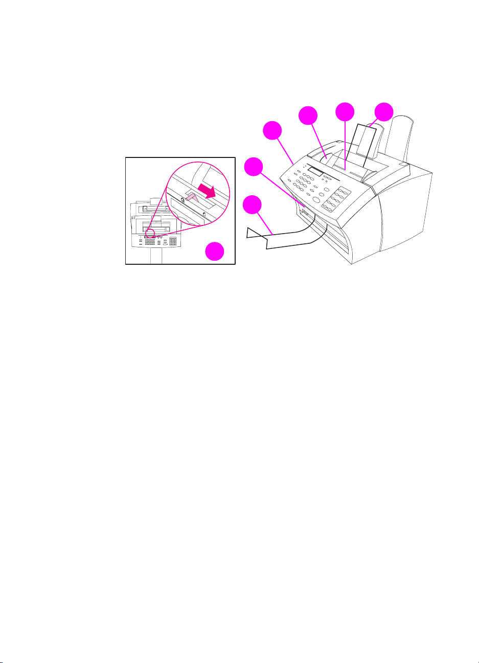
2
1
7
Figure 2. Document sca nner path
Document output support
1
Document output slot
2
Document release door/control panel
3
Document feeder tray guides
4
Document feeder tray
5
4
5
6
EN
Document feeder support
6
Special media lever
7
Product overview 19
Page 22
4
5
6 7
3
2
1
Figure 3. Printer path (1 of 2)
1 Front paper output
2 Paper path lever
3 Control panel
4 Printer door
5 Printer door release latches
6 Paper output support
7 Paper input support
5
20 Product Information
EN
Page 23
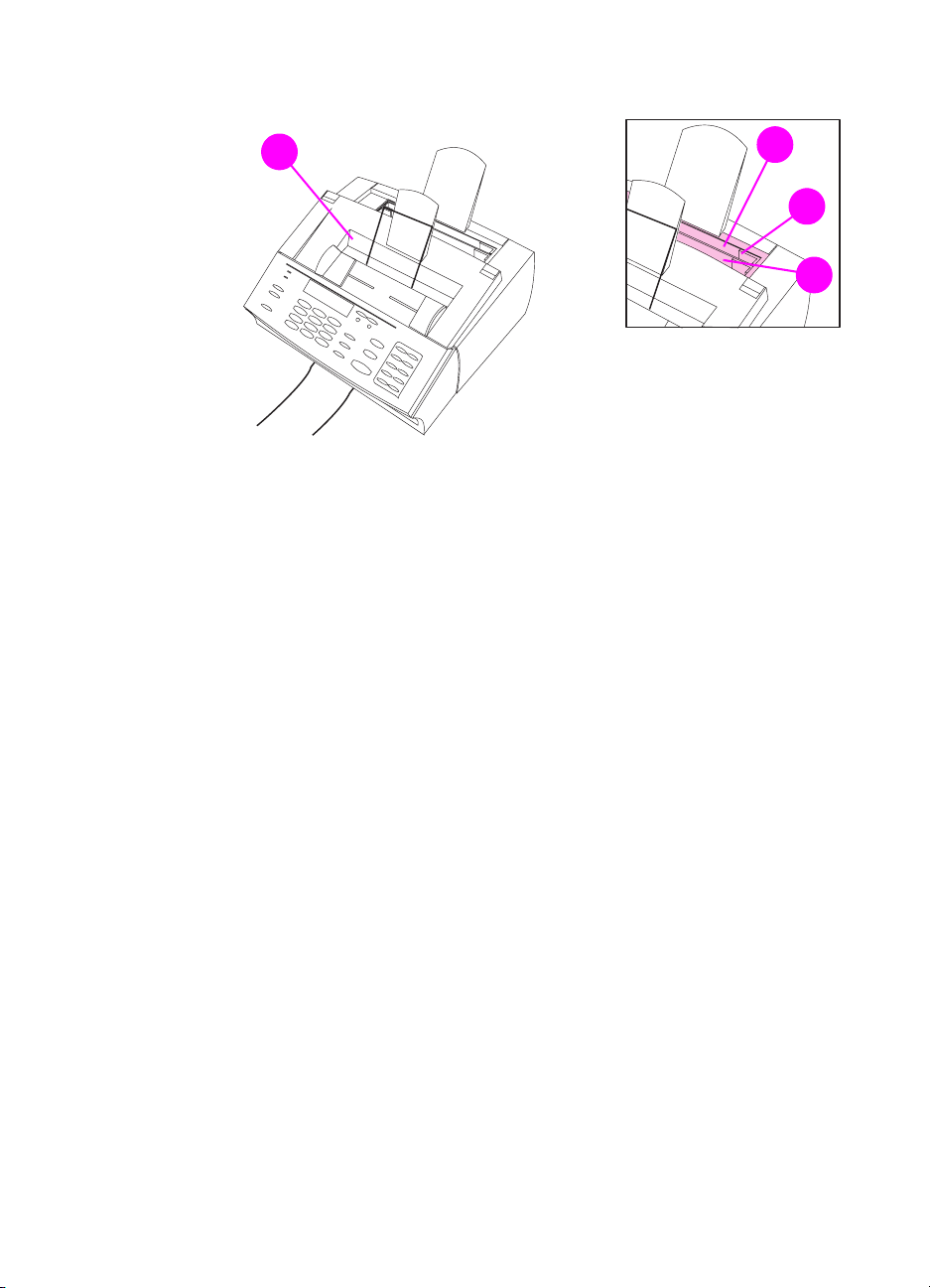
1
Figure 4. Printer path (2 of 2)
Output bin
1
Input bin
2
Paper guides
3
Single-sheet input slot
4
2
3
4
EN
Product overview 21
Page 24
2
3
1
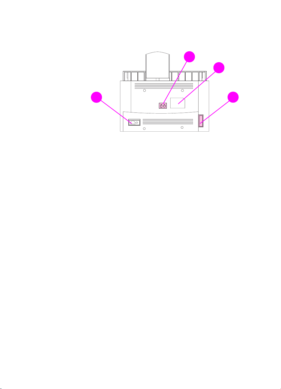
Figure 5. Rear view
1 Power cable connector
2 Phone line connector (or connectors, depending on country)
3 Model and serial number label
4 Parallel cable connector
4
22 Product Information
EN
Page 25

R egulator y information
Safety
Transporta tion
Non-operating Magnetic Field Emissions, IAT A Pac kaging Instructions
902
La ser sa fety sta teme nt
The Center for Devices and Radiological Health (CDRH) of the U.S.
Food and Drug Administration has implemented regulations for laser
products manufactured since August 1, 1976. Compliance is
mandatory for products marketed in the United States. This printer is
certified as a “Class 1” laser product under the U.S. Department of
Health and Human Services (DHHS) Radiation Performance
Standard according to the Radiation Control for Health and Safety Act
of 1968. Since radiation emitted inside this printer is completely
confined within protective housings and external covers, the laser
beam cannot escape during any phase of normal user operation.
WARNING!
Using controls, making adjustments, or performing procedures other
than those specified in this manual may result in e xposure to hazardous
radiation.
EN
Regulatory information 23
Page 26

La ser sta tement for F inland
Luoka n 1 la serlaite
Kla ss 1 Laser Appa r at
HP LaserJet 3100/3150 laserkirjoitin on käyttäjän kannalta turvallinen
luokan 1 laserlaite. Normaalissa käytössä kirjoittimen suojakotelointi
estää lasersäteen pääsyn laitteen ulkopuolelle.Laitteen
turvallisuusluokka on määritetty standardin EN 60825-1 (1994)
mukaisesti.
Varoitus!
Laitteen käyttäminen muulla kuin käyttöohjeessa mainitulla tavalla
saattaa altistaa käyttäjän turvallisuusluokan 1 ylittävälle
näkymättömälle lasersäteilylle.
Varning !
Om apparaten används på annat sätt än i bruksanvisning
specificerats, kan användaren utsättas för osynlig laserstrålning, som
överskrider gränsen för laserklass 1.
HUOLTO
HP LaserJet 3100/3150 -kirjoittimen sisällä ei ole käyttäjän
huollettavissa olevia kohteita. Laitteen saa avata ja huoltaa
ainoastaan sen huoltamiseen koulutettu henkilö. Tällaiseksi
huoltotoimenpiteeksi ei katsota väriainekasetin vaihtamista,
paperiradan puhdistusta tai muita käyttäjän käsikirjassa lueteltuja,
käyttäjän tehtäväksi tarkoitettuja ylläpitotoimia, jotka voidaan
suorittaa ilman erikoistyökaluja.
Varo!
Mikäli kirjoittimen suojakotelo avataan, olet alttiina näkymättömälle
lasersäteilylle laitteen ollessa toiminnassa. Älä katso säteeseen.
Varning !
Om laserprinterns skyddshölje öppnas då apparaten är i funktion,
utsättas användaren för osynlig laserstrålning. Betrakta ej strålen.
Tiedot laitteessa käytettävän laserdiodin säteilyominaisuuksista:
24 Product Information
Aallonpituus 775-795 nm
Teho 5 mW
Luokan 3B laser
EN
Page 27

F CC regulations
This equipment has been tested and found to comply with the limits
for a Class B digital device, pursuant to Part 15 of the FCC rules.
These limits are designed to provide reasonable protection against
harmful interference in a residential installation. This equipment
generates, uses, and can radiate radio frequency energy. If is not
installed and used in accordance with the instructions, it may cause
harmful interference to radio communications. However, there is no
guarantee that interference will not occur in a particular installation.
If this equipment does cause harmful interference to radio or
television reception, which can be determined by turning the
equipment off and on, the user is encouraged to try to correct the
interference by one or more of the following measures:
● Reorient or relocate the receiving antenna.
● Increase separation between equipment and receiver.
● Connect equipment to an outlet on a circuit different from that to
which the receiver is located.
● Consult your dealer or an experienced radio/TV technician.
Note
Note
Any changes or modifications to the printer that are not expressly
approved by HP could void the user’s authority to operate this
equipment.
Use of a shielded interface cable is required to comply with the Class
B limits of Part 15 of FCC rules.
F CC part 6 8 re quireme nts
This equipment complies with FCC rules, Part 68. On the back of this
equipment is a label that contains, among other information, the FCC
registration number and ringer equivalence number (REN) for this
equipment. If requested, this information must be provided to the
telephone company.
The REN is used to determine the quantity of devices which may be
connected to the telephone line. Excessive RENs on the telephone
line may result in the devices not ringing in response to an incoming
call. In most, but not all, areas, the sum of the RENs should not
exceed five (5.0). To be certain of the number of devices that may be
connected to the line, as determined by the total RENs, contact the
telephone company to determine the maximum REN for the calling
area.
EN
Regulatory information 25
Page 28

This equipment uses the following USOC jacks:
RJ11C
An FCC-compliant telephone cord and modular plug is provided with
this equipment. This equipment is designed to be connected to the
telephone network or premises wiring using a compatible modular
jack which is Part 68 compliant.
This equipment cannot be used on telephone company-provided coin
service. Connection to Party Line Service is subject to state tariffs.
If this equipment causes harm to the telephone network, the
telephone company will notify you in advance that temporary
discontinuance of service may be required. If advance notice isn’t
practical, the telephone company will notify the customer as soon as
possible. Also , y ou will be advised of y our right to file a complaint with
the FCC if you believe it is necessary.
The telephone company may make changes in its facilities,
equipment, operations, or procedures that could affect the operation
of the equipment. If this happens, the telephone company will provide
advance notice in order for you to make the necessary modifications
in order to maintain uninterrupted service.
If trouble is experienced with this equipment, please see the numbers
in the front of this manual for repair and (or) warranty information.
If the trouble is causing harm to the telephone network, the telephone
company may request you remove the equipment from the network
until the problem is resolved.
The following repairs can be done by the customer:
Replace any original equipment that came with the HP LaserJet
3100/3150 product. This includes the toner cartridge, the supports for
trays and bins, the power cord and the telephone cord.
It is recommended that the customer install an AC surge arrestor in
the AC outlet to which this device is connected. This is to avoid
damage to the equipment caused by local lightning strikes and other
electrical surges.
26 Product Information
EN
Page 29

Tele phone consumer prote ction act (U.S. )
The Telephone Consumer Protection Act of 1991 makes it unlawful
for any person to use a computer or other electronic de vice , including
fax machines, to send any message unless such message clearly
contains, in a margin at the top or bottom of each transmitted page or
on the first page of the transmission, the date and time it is sent and
an identification of the business, other entity, or individual sending the
message and the telephone number of the sending machine or such
business, other entity, or individual. (The telephone number provided
may not be a 900 number or any other number for which charges
exceed local or long-distance transmission charges.)
In order to program this information into your facsimile, please see
“Setting the fax header” and “Setting the time and date” in the user
guide.
EN
Regulatory information 27
Page 30

IC CS-03 requirements
NOTICE: The Industry Canada label identifies certified equipment.
This certification means that the equipment meets certain
telecommunications network protective, operational and safety
requirements as prescribed in the appropriate Terminal Equipment
Technical Requirement document(s). The Department does not
guarantee the equipment will operate to the user’s satisfaction.
Before installing this equipment, users should ensure that it is
permissible to be connected to the facilities of the local
telecommunications company. The equipment must also be installed
using an acceptable method of connection. The customer should be
aware that compliance with the above conditions may not prevent
degradation of service in some situations.
Repairs to certified equipment should be coordinated by a
representative designated by the supplier. Any repairs or alterations
made by the user to this equipment, or equipment malfunctions, may
give the telecommunications company cause to request the user to
disconnect the equipment.
Users should ensure for their own protection that the electrical ground
connections of the power utility, telephone lines and internal metallic
water pipe system, if present, are connected together. This
precaution may be particularly important in rural areas.
Caution: Users should not attempt to make such connections
themselves, but should contact the appropriate electric inspection
authority, or electrician, as appropriate.
The Ringer Equivalence Number (REN) of this device is 0.7.
NOTICE: The Ringer Equivalence Number (REN) assigned to each
terminal device provides an indication of the maximum number of
terminals allowed to be connected to a telephone interface. The
termination on an interface may consist of any combination of de vices
subject only to the requirement that the sum of the Ringer
Equivalence Number of all the devices does not exceed 5.
The standard connecting arrangement code (telephone jack type) for
equipment with direct connections to the telephone network is
CA11A.
28 Product Information
EN
Page 31

D ecla r ation of confor mity
according to ISO/IEC Guide 22 and EN 45014
Manufacturer’s Name: Hewlett-Packard Company
Manufacturer’s Address: 11311 Chinden Boulevard
Boise, Idaho 83714-1021, USA
declares, that the product
Product N ame: HP LaserJet 3100/3150 product
Model Number: CxxxxA
Product O p tions:ALL
conforms to the following Product Specifica tions :
Safety: IEC 950:1991+A1+A2+A3 / EN 60950:1992+A1+A2+A3
EMC: CISPR 22:1993+A1 / EN 55022:1994 Class B
Supplementa ry Infor mation:
The product herewith complies with the requirements of the following Directives and carries the CEmarking accordingly:
- the EMC directive 89/336/EEC
- the Low Voltage Directive 73/23/EEC
1
This product was tested in a typical configuration with Hewlett-Packard Personal Computer Systems.
2
This Device complies with part 15 of the FCC Rules. Operation is subject to the following two
conditions: (1) this device may not cause harmful interference, and (2) this device must accept any
interference received, including interference that may cause undesired operation.
March 25, 1997
For Compliance Information ONLY, contact:
Australia Contact: Product Regulations Manager, Hewlett-Packard Australia Ltd., 31-41 Joseph Street,
EN 41003:1993
IEC 825-1:1993 / EN 60825-1:1994 Class 1 (Laser/LED)
EN 50082-1:1992
IEC 801-2:1991 / prEN 55024-2:1992-3kV CD, 8kV AD
IEC 801-3:1984 / prEN 55024-3:1991-3 V/m
IEC 801-4:1988 / prEN 55024-4:1992-0.5 kV Signal Lines
IEC 1000-3-2:1995 / EN61000-3-2:1995
IEC 1000-3-3:1994 / EN61000-3-3:1995
FCC Title 47 CFR, Part 15 Class B
2
/ ICES-003, Issue 2
AS / NZS 3548:1995 / CISPR 22:1993 Class B
Blackburn, Victoria 3130, Australia
1
1.0 kV Power Lines
1
European Contact: Your Local Hewlett-Packard Sales and Service Office or Hewlett-Packard Gmbh,
Department HQ-TRE / Standards Europe, Herrenberger Strasse 130, D-71034
Böblingen (FAX: +49-7031-14-3143)
USA Contact: Product Regulations Manager, Hewlett-Packard Company, PO Box 15, Mail Stop 160,
Boise, ID, 83707-0015 (Phone: 208-396-6000)
EN
Regulatory information 29
Page 32

C ana dian D OC regulations
Complies with Canadian EMC Class B requirements.
Conforme á la classe B des normes canadiennes de compatibilité
électromagnétiques. << CEM>>.
E nvironmenta l product stewardship progr am
P rote cting the e n vironment
Hewlett-Packard Company is committed to providing quality products
in an environmentally sound manner. This HP LaserJet printer has
been designed with several attributes to minimize impacts on our
environment.
This HP LaserJet printer design eliminates:
Ozone production
The printer does not use high-voltage corona wires in the
electrophotographic process and therefore generates no appreciable
ozone gas (O
cartridge and in the print engine.
This HP Lase rJet printer design reduces:
). Instead, this printer uses charging rollers in the toner
3
Energy consumption
Energy usage drops to as little as 9 watts while in idle mode. Not only
does this save natural resources, but it also saves money without
affecting the high performance of this product. This product qualifies
for the E
established to encourage the development of energy-efficient office
products. E
Environmental Protection Agency.
30 Product Information
NERGY STAR
NERGY STAR
. E
NERGY STAR
is a voluntary program
is a U.S. registered service mark of the U.S.
As an E
NERGY STAR
partner, HewlettPackard Company has determined that
this product meets E
NERGY STAR
Guidelines for energy efficiency.
EN
Page 33

Toner consumption
Depending on the type of printer driver you have, you may be able to
select a “draft” mode which uses about 50% less toner, thereby
extending the life of the toner cartridge. This is only available using
printer driver properties when printing or making copies from the
software.
Paper use
Depending on the type of program you use, y ou ma y be able to print 2
or 4 document pages on each printed page. This “N-up” printing
practice and the printer’s manual duplex capability (two-sided
printing) reduce paper usage and the resulting demands on natural
resources.
The design of this HP LaserJet printer facilitates the recycling of:
Plastics
Plastic parts have marking according to international standards that
enhance the ability to identify plastics for recycling purposes at the
end of the product’s life.
HP LaserJe t Printing S upplies
In many countries, this product's printing supplies (e.g., toner
cartridge, drum, fuser) can be returned to HP through the HP Planet
Partners Printing Supplies Environmental Program. An easy-to-use
and free takeback program is available in more than 20 countries.
Multilingual program information and instructions are included in
every new HP LaserJet toner cartridge and consumables package.
EN
HP Planet Partners Printing Supplies Environmental Program
Information
Since 1990, the HP LaserJet Toner Cartridge Recycling Program has
collected more than 25 million used LaserJet toner cartridges that
otherwise may have been discarded in the world's landfills. The HP
LaserJet toner cartridges and consumables are collected and bulk
shipped to our resource and recovery partners who disassemble the
cartridge. After a thorough quality inspection, selected parts such as
nuts, screws, and clips are reclaimed for use in new cartridges.
Remaining materials are separated and converted into raw materials
for use by other industries to make a variety of useful products.
Returns
For a more environmentally responsib le return of used cartridges and
consumables, HP encourages the use of bulk returns. Simply bundle
two or more cartridges or consumables together and use the single,
pre-paid, pre-addressed UPS label that is supplied in the package.
Regulatory information 31
Page 34

For more information in the U.S. or Canada, call (1) (800) 340-2445
(U.S.) or (1) (800) 387-3867. Or, visit the HP LaserJet Supplies
website at the following address:
http://www.ljsupplies.com/planetpartners/
For more information in Mexico, call 258-40-44 (Mexico City) or (1)
(800) 900-7200 (outside Mexico City). Or, visit the website at the
following address:
http://www.hp.com/latinamerica
All other customers should call their local HP Sales and Service
Office or visit the following websites for further information regarding
availability of the HP Planet Partners LaserJet Toner Cartridge and
Consumables Recycling Program:
Latin America: http://www.hp.com/latinamerica
Asia/Pacific Region: http://www.asiapacific.hp.com/planp1
Europe: http://www.hp.com/pays/eur_supplies/english/planetpartners
Paper
This printer is suited for the use of recycled papers when the paper
meets the guidelines outlined in the HP LaserJet Printer Family P aper
Specification Guide (HP part number 5040-9072). This printer is
suited for the use of recycled paper according to DIN 19 309.
To ensure longevity of your HP LaserJet printer, HP provides the
following:
Extended w arra nty
HP SupportPack provides cov er age for the HP hardware product and
all HP-supplied internal components. The hardware maintenance
covers a three-year period from date of the HP product purchase. HP
SupportPack must be purchased by the customer within 90 days of
the HP product purchase. Information on HP SupportPack is av ailable
in a fax format by calling the U.S. HP FIRST (Fax Information
Retrieval Support Technolog y) at (800) 333-1917.
After connecting, press 1, and then press 1 again. The document
number is 9036. International customers can contact the nearest
HP-authorized reseller about this service.
If you hav e access to the internet, please try the HP Support Services
website about HP Support Pack at the following address:
http://www.hp.com/ssg/serv.pack.html
The following website contains worldwide customer service and
support contact information:
http://www.hp.com/ssg/contact/world.html
32 Product Information
EN
Page 35

Spare parts and consuma bles a vailability
Spare parts and consumable supplies for this product will be made
available for at least five years after production has stopped.
EN
Regulatory information 33
Page 36

M ate ria l safe ty data sheet
The Material Safety Data Sheet (MSDS) can be obtained by
contacting the fax-on-demand service in the HP LaserJet Supplies
website at the following address:
http://www.hp.com/go/msds
If you do not have access to the internet, call U.S. HP FIRST at
(800) 231-9300. After connecting, press 1. Then, request document
number 10164.
Non-U.S. customers should refer to the HP LaserJet 3150 product
user guide for HP FIRST phone numbers and information.
34 Product Information
EN
Page 37

Installation and
2
operation
C hapter conte nts
Operating environment . . . . . . . . . . . . . . . . . . . . . . . . . . . . . . . . . . 36
Media requirements. . . . . . . . . . . . . . . . . . . . . . . . . . . . . . . . . . . . . 37
Toner cartridge information . . . . . . . . . . . . . . . . . . . . . . . . . . . . . . . 38
Control panel. . . . . . . . . . . . . . . . . . . . . . . . . . . . . . . . . . . . . . . . . . 39
EN
Chapter contents 35
Page 38

Operating environment
The environmental requirements listed below must be maintained to
ensure the proper operation of the HP LaserJet 3100/3150 product.
Table 7. Environme ntal requirements
Category Requirement
Operating (working or
standby)
Non-operating Temperature (toner cartridge): -4 to 104°F (-20 to 40°C);
Normal storage Temperature: 32 to 95°F (0 to 35°C)
Temperature: 59 to 90.5 degrees Fahrenheit
(15 to 32.5 degrees Celsius)
Humidity: 10 to 80 percent relative humidity (no condensation)
Temperature (product): -4 to 140°F (-20 to 60°C)
Humidity: 10 to 90 percent relative humidity (no condensation)
Humidity: 35 to 85 percent relative humidity
Consider the following before installing the printer:
● Install in a well-ventilated, dust-free area.
● Install on a hard, flat, continuous surface, with all four feet level.
Do not install on carpet or other soft surfaces.
● Ensure adequate power is supplied.
Note Uninterruptible power supplies (UPS) may be used with the
HP LaserJet 3100/3150 product.
● Install away from direct sunlight, open flames , or ammonia fumes.
If the HP LaserJet 3100/3150 product is placed near a window,
make sure the window has a curtain or blind to block direct
sunlight.
● Install with enough space around the product for proper access
and ventilation.
● Install away from the direct flow of exhaust from air ventilation
systems.
36 Installation and operation
EN
Page 39

M edia require ments
Media must be in good condition. Do not use media that is torn, worn,
or irregular. The table below details media requirements of the HP
LaserJet 3100/3150 product.
Table 8. Media requirements
Input for paper input bin and single -sheet input slot (for pr inter pa th)
Media size Maximum: 8.5 by 14 in (216 by 356 mm)
Minimum: 3 by 5 in (76.2 by 127 mm)
Media weight
For paper output bin: 16 to 28 lb; (60 to 105 g/m
For front output slot: 16 to 42 lb (60 to 157 g/m
Paper input bin capacity
Up to 100 sheets of media at 20 lb (75 g/m
(fewer than 100 sheets of heavier media) or up to 10 envelopes
Input for document feede r tray (for document scanner pa th)
Item size Maximum width: 8.5 in (216 mm)
Maximum length: 39 in (991 mm); up to 118 in (2997.2 mm) with
“long pages” enabled
Minimum size: 2 by 3.5 in (51 by 89 mm)
Item weight
Document feeder tray
capacity
Maximum: 28 lb (105 g/m
up to 67 lb (252 g/m
Minimum: 12 lb (44 g/m
Up to 30 pages of an item at 20 lb (75 g/m
Fewer than 30 pages of items up to 28 lb (105 g/m
2
) for normal use;
2
) when using special media lever
2
)
One page at a time of 12 to 67 lb (44 to 252 g/m
special media lever
Output capacities
2
)
2
)
2
) weight or lighter
2
) weight or lighter
2
) weight
2
) weight using
Paper output bin
Front paper output slot
Document output tray
EN
Up to 100 sheets of 20 lb (75 g/m
Up to 20 pages of 20 lb (75 g/m
2
) or lighter paper
2
) or lighter paper
Up to 30 pages of an item at 28 lb (105 g/m
Media requirements 37
2
)
Page 40

Toner cartr idge informa tion
Toner cartridges contain components that are sensitive to light,
temperature, and humidity. Follow the recommendations in this
section to ensure the highest quality and longest life of HP toner
cartridges.
Keep the HP LaserJet 3100/3150 product within the following
environmental conditions for optimum performance.
S torage conditions
Toner cartridges are affected by their environment. Packaging
protects toner cartridges from light and increases storage life. It is
important to store cartridges in their original packaging until ready for
installation.
When storing cartridges in a warehouse or work area, make sure the
storage place meets the conditions specified in Table 6.
S tor ing opened tone r cartr idge s
Because cartridges do not have shutters to cover the laser beam
access slot, they should be kept inside the HP LaserJet 3100/3150
product until empty. Toner cartridges that have had the toner sealing
tape removed are also more vulnerable to environmental extremes.
If a toner cartridge must be removed from the HP LaserJet 3100/3150
product, always store the cartridge:
● Inside the protective bag in which it was originally packaged.
● In a dark cabinet, away from direct sunlight.
● Correct side up and in a horizontal position (not standing on end).
● Away from ammonia or organic solvent fumes.
CAUTION Never ship the HP LaserJet 3100/3150 product with a toner cartridge
installed. Excessive vibration during shipping can cause toner to leak,
contaminating the product and possibly damaging the drum. Never
expose a cartridge to direct sunlight or to room light for more than a
few minutes. Bright light can permanently damage a toner cartridge.
Toner R ecycling
See recycling information in Chapter 1.
38 Installation and operation
EN
Page 41

C ontrol panel
1
2
3
4
5
8
9
18
6
7
17
16
12
15
Figure 6. Control pane l layout
1. Ready light 7. Forward arrow key 13. Speed-dial key
2. Error light 8. Stop/clear key 14. Redial/pause key
3. Control panel display 9. Copy key 15. Numeric keys
4. Enter/menu key 10. One-touch keys 16. Volume key
5. Backspace key 11. Start key 17. Resolution key
14
13
11
10
6. Back arrow key 12. Manual dial key 18. Contrast key
EN
Control panel 39
Page 42

C ontrol pane l messa ges
These control panel messages are listed alphabetically, and are
accompanied by the cause for the message and steps to take to
resolve the problem.
Table 9. Control panel messages
Message Cause Solution
(number) is a Group
Group not Allowed
Already in Group While programming a group-dial code,
Blacklisted
(France only)
Busy The fax line to which you sent a fax was
Cancel Group Edit
ENTER to Confirm
The group-dial code you entered is
assigned to a group, but a group cannot
be dialed at this point. (Entries assigned
as groups cannot be assigned into other
groups.)
you tried to add a fax number that is
already in the group.
The fax number you tried to dial has
received a voice answer or no answer,
was busy on the first dial and redials, or
was busy with redials pending.
busy . The HP LaserJet 3100/3150 product
automatically redials the busy line the
number of times specified.
You pressed B
dial code in the Group Dial Setup Menu.
ACK SPACE
while in a group-
Enter a different one-touch key or
speed-dial code that is not assigned.
Continue by adding the next fax number
you want to the group.
To clear the blacklist, unplug the fax
machine’s power cord from the power
strip or outlet and plug it back in.
Check the fax number and try again to
send the fax. If the message appears
again, try to send the fax to another fax
machine or try again later.
TART
Press S
code and continue editing.
Press E
Dial Setup Menu. (Press E
again to choose a different group-dial
code.)
Press S
settings.
to return to the group-dial
NTER/MENU
TOP/CLEAR
to go to the Group
NTER/MENU
to exit the Menu
40 Installation and operation
EN
Page 43

Table 9. Control panel messages
Message Cause Solution
Clear Document
From Scanner
Your document jammed while being fed
through the document feeder tray or the
HP LaserJet 3100/3150 product loaded
multiple sheets of the document.
The special media lever was in the wrong
position for the document you sent.
The control panel configuration was set
incorrectly.
Open the document release door,
remove the jammed item, and then
close the door.
Remove the jammed item as detailed
above. Then, check the special media
lever. It should be to the left for regularweight items or to the right for thick or
light items, which must be fed one at a
time.
Check the control panel configuration f or
outgoing faxes, including the “send long
pages” setting.
EN
Control panel 41
Page 44

Table 9. Control panel messages
Message Cause Solution
Communication Error An error occurred while trying to transmit
a fax. Brief descriptions of communication
errors are listed below:
60 no RTC at end of fax
81 memory filled up
82 fax was too short
84 power fail while receiving
85 failed to train
86 in ECM, fax data had error(s)
87 NEC failed to decode (T.4 or T.6
coding error
88 received scan line exceeds 13 sec
(T.4-3.2)
89 modem setup timeout
90 low speed command time out
91 bad low speed command
92 transmit error: no DIS
93 transmit error: no answer
94 transmit error: canceled by operator
95 transmit error: failed to train
96 transmit error: busy
97 transmit error: no dial tone
100 poll-in error: no document to poll
101 document jam
102 receive error: too many mailbox
logs
103 receive error: had poll document but
no memory for receive
104 transmit error: no MCF
105 image processing chip fell behind
106 transmit: modem output buffer error
107 PIN received
108 RR/RNR timeout
109 generic ECM error
110 possible missing/partial pages in
ECM
111 T4 bit not set in DIS
112 wrong pass word
113 communications error in remote
setup (JetFax only)
114 fax document was lost (JetFax only)
115 blacklist
116 SUB/PWD error
117 timeout waiting for image
processing chip
118 no fax detected
119 remote access
120 caller disconnected prematurely
Try again to send the fax.
Try to send the fax to another fax
machine.
Make sure the telephone cord is
securely connected. Then, check for a
dial tone on the phone line by pressing
ANUAL DIAL
M
Make sure the phone line is working by
disconnecting the HP LaserJet 3100/
3150 product, plugging in a telephone to
the phone line, and making a voice call.
Connect the product to a different phone
line.
Reset the product by pressing and
holding S
Wait and try resending the fax later.
.
TOP/CLEAR
for seven seconds.
42 Installation and operation
EN
Page 45

Table 9. Control panel messages
Message Cause Solution
Configuration
Err # (number 1-4)
Config. Stuck Addr In Service Mode only, SRAM stuck
Config. Tied Addr. In Service Mode only, SRAM tied address
Decoding Error #
(number 1-3)
An error was detected in the SRAM. Unplug the power cord from the power
address test.
test.
There was an error in decoding with the
image processing chip.
source, wait 10 seconds, and replug in
the power cord.
Try plugging the power cord into a
different power source.
If the error persists, see Chapter 6,
“Troubleshooting.”
Unplug the power cord from the power
source, wait 10 seconds, and replug in
the power cord. If the error persists, se e
Chapter 6, “Troubleshooting.”
Unplug the power cord from the power
source, wait 10 seconds, and replug in
the power cord. If the error persists, se e
Chapter 6, “Troubleshooting.”
Unplug the power cord from the power
source, wait 10 seconds, and replug in
the power cord.
Try plugging the power cord into a
different power source.
If the error persists, see Chapter 6,
“Troubleshooting.”
Documents Were
Lost START to
Continue
Encoding Error There was an error in encoding with the
Errors Likely in
Pages
EN
Power to the HP LaserJet 3100/3150
product was interrupted, and documents
in memory were lost.
image processing chip.
The fax transmission was completed, but
there are likely to be errors in the pages
specified.
TART
Press S
3150 product prints a report. Check the
Status column for the “Fax Document
was Lost” message. The associated
incoming and outgoing faxes should be
resent.
Unplug the power cord from the power
source, wait 10 seconds, and replug in
the power cord. If the error persists, se e
Chapter 6, “Troubleshooting.”
Try resending the fax or asking the
sender to resend the fax to you.
Try faxing to another fax number.
Try connecting the product to a different
phone line.
. The HP LaserJet 3100/
Control panel 43
Page 46

Table 9. Control panel messages
Message Cause Solution
Fax Document was
Lost
Fax Memory Error
#(number 1-5)
Group is Empty, Use
ONE-TOUCH/
SPEED DIAL
Input Limit Reached Too many fax numbers were dialed when
Invalid Date or Time An invalid time or date was entered, such
Fax es in memory were lost as a result of a
power failure.
An error was detected in DRAM. Unplug the power cord from the power
Appears when you are creating a groupdial code.
you tried to send to an ad-hoc group.
as 25:99 PM or June 35
If you set up faxes to be sent at a future
time or to be polled, or if the product
was set to receive faxes to memory,
print a fax log to identify the lost faxes.
The lost faxes should be resent.
source, wait 10 seconds, and replug in
the power cord.
Try a different power source or surge
protector.
If the error persists, see Chapter 6,
“Troubleshooting.”
Begin adding fax numbers to the groupdial code. For more information, see
“Programming group-dial codes from
the control panel” in the user guide.
The maximum number of fax numbers
that can be added to an ad-hoc group is
100. Resend the fax to 100 or fewer
numbers.
Re-enter the date and time. If the error
persists, see Chapter 6,
“Troubleshooting.”
Keypad Test Failed In Service Mode only, the keypad test
failed.
Long Page?
START to Continue
The HP LaserJet 3100/3150 product
senses a document over 39 inches (991
mm), such as a banner, may be feeding
through the document feeder tray or that a
paper jam has occured.
44 Installation and operation
Check the cabling connections and run
the keypad test again.
If the error persists, see Chapter 6,
“Troubleshooting.”
If there is no jam, quickly press S
continue scanning. If you do not press
TART
S
within a f ew seconds , the product
assumes that a page is jammed and
cancels the job.
If there is a jam, remove it and restart
the job.
If you are sending a fax or copying a
document longer than 39 inches (991
mm), you can also set the control panel
to use the “Send long pages” procedure.
TART
to
EN
Page 47

Table 9. Control panel messages
Message Cause Solution
Memory Full - Send
Unscanned Pages
Memory is Full The HP LaserJet 3100/3150 product
Modem Error #
(number 1-3)
No Answer You tried to send a fax, but the receiving
No Dial Tone The HP LaserJet 3100/3150 product
During the fax job the memory filled. All
pages of the fax have to be in memory for
a fax job to work correctly. Only the pages
that fit into memory were sent.
memory was completely filled during a
copy or a scan.
An error was detected with the modem. Make sure that the telephone cord is
fax line did not answer.
cannot detect a dial tone
Reload the pages that were not sent
and send them.
This message should clear
automatically when the next task starts
(for example when you start a copy or
receive a fax).
securely connected on both ends.
Unplug the power cord from the power
source, wait 10 seconds, and replug in
the power cord.
Try a different power source or surge
protector.
Check the fax number and try again to
send the fax.
Try to send the fax to another fax
machine or try again later.
Make sure that the telephone cord is
securely connected on both ends.
Press and hold S
seconds to check for a dial tone.
Make sure the phone line is working by
disconnecting the HP LaserJet 3100/
3150 product, plugging in a telephone to
the phone line, and making a voice call.
Connect the product to a different phone
line.
TOP/CLEAR
for seven
No Fax in (number)
Tries
EN
The HP LaserJet 3100/3150 product f ailed
to connect to the receiving fax machine in
the number of redials specified.
Check the fax number and try again to
send the fax. If the message appears
again, try to send the fax to another fax
machine or try again later.
Control panel 45
Page 48

Table 9. Control panel messages
Message Cause Solution
No Memory for
Report
Erase/Print
Document
No Modem Installed There is a problem with the line interface
No Room in Fax Log The fax log was unable to print because of
Not Enough Memory There is not enough memory to complete
There is not enough memory to print a
report because memory is being used to
store faxes that have been received to
memory.
There is not enough memory to print a
report because memory is being used to
store faxes set up to be sent at a future
time or to be polled.
unit (LIU).
an error; for example, the product is out of
paper.
the job indicated.
Print faxes that have been received to
memory.
If you have several faxes set up to be
sent at a future time or to be polled, try
clearing these faxes using job status.
Unplug the power cord from the power
source, wait 10 seconds, and replug in
the power cord.
Connect the product to a different power
source.
If the error persists, see Chapter 6,
“Troubleshooting.”
Solve the error condition so that the
product can print the fax log.
Try again to send the job. If the error
persists, press and hold S
seven seconds to reset the product.
TOP/CLEAR
for
Not Enough Memory
to Duplicate for
COPY
No Fax Pages in
Memory to Reprint
Nov-22-93 06:30 PM
(An incorrect date
appears.)
The HP LaserJet 3100/3150 product does
not have enough memory to complete the
copy job.
The HP LaserJet 3100/3150 product
attempted to execute “Reprint Last Fax”
when nothing was in memory.
The battery inside the HP LaserJet 3100/
3150 product has failed, causing all Menu
features to revert to the factory settings.
Settings that contained alphabetic and
numeric characters you entered, such as
header information and speed-dial names
and numbers, have been erased.
46 Installation and operation
Divide the copy job into smaller sections
and then try again to copy.
Use the Document Assistant to
complete the copy job.
Wait for a f ax, then as soon as a fax is in
the memory, the HP LaserJet 3100/
3150 product will reprint the fax.
The battery should be replaced. You can
continue to use the HP LaserJet 3100/
3150 product without replacing the
battery, but any information you enter
will be erased again if power is lost.
EN
Page 49

Table 9. Control panel messages
Message Cause Solution
Paper Bin is Empty
Please Add Paper
Password must be 4
Digits
Paused (Memory
Full)
PC Not Detected
Address Invalid
The paper input bin is empty. Load paper. If paper is already loaded,
remove it. Check for and remove any
jammed sheets and discard them. Then,
reload the paper stack in the paper input
bin.
An attempt was made to enter a password
that was not four digits.
The HP LaserJet 3100/3150 product
memory is full, and the current job in the
document feeder tra y is pa used to w ait for
memory to become available.
If you tried to send a document to an email address in a one-touch key, speeddial code, group-dial code, or to one that
you entered manually at the control panel,
the product must be directly connected to
a computer using a parallel cable, the
computer must be on, and a compatible email program must be installed on the
computer.
Re-enter four-digit password.
Reduce activity on the HP LaserJet
3100/3150 product, or wait for other jobs
to finish so that memory will be freed.
If there are faxes set up to be polled or
sent at a future time, you may want to
cancel these jobs to free memory.
Make sure that the parallel cable is
securely connected between the
computer and the HP LaserJet
3100.3150 product.
Make sure that the computer is on.
Make sure that a compatible e-mail
program and the JetSuite Pro software
are installed on the computer.
PC Print Timed Out The print job took too long to print, and the
HP LaserJet 3100/3150 product timed
out.
Phone Number Error Too many characters were entered when
dialing a phone number.
EN
Let the “print jobs retry” continue for five
minutes. If the HP LaserJet 3100/3150
product still does not print, cancel the
current print job and resend it.
The maximum number of characters
that can be entered is 60. If you have a
number longer than 60 characters,
break the number into smaller chunks.
Enter the first part of the number, and
EDIAL/PAUSE
press R
character in the first number. Then,
enter the second part of the number as
if it were a second number going to a
group. When the product dials, it will
treat both numbers as if they are one.
as the last
Control panel 47
Page 50

Table 9. Control panel messages
Message Cause Solution
Polling-In Error The HP LaserJet 3100/3150 product tried
to poll another fax machine. The poll failed
because there was no answer, the line
was busy, or the other fax machine was
not ready to be polled.
Printer Comm Error There was an error in communicating with
the HP LaserJet 3100/3150 product.
Printer Comm Error ^1In Service Mode only. There was an error
in communicating with the HP LaserJet
3100/3150 product.
Make sure that the sender’ s fax ma chine
is ready to be polled, and check the fax
number. Then, set up to poll again.
Make sure that the parallel cable is
securely connected between the HP
LaserJet 3100/3150 product and the
computer.
If the problem persists, unplug the
power cord from the power source for 10
seconds, and then replug it in.
Try connecting the product to a different
power source.
If the error persists, see Chapter 6,
“Troubleshooting.”
Make sure that the parallel cable is
securely connected between the HP
LaserJet 3100/3150 product and the
computer.
If the problem persists, unplug the
power cord from the power source for 5
seconds, and then replug it in.
If neither of these solutions works, see
Chapter 6, “Troubleshooting.”
Printer Cover Open
or No Cartridge
Printer Fixing Error
Replace Fixing Unit
The printer door is open or the toner
cartridge is not installed properly.
There is an error with the print engine. Unplug the power cord from the power
48 Installation and operation
Make sure that the printer door is
closed.
Check the toner cartridge for proper
installation.
source for 10 seconds, and then replug
it in.
Try connecting the product to a different
power source.
If the error persists, see Chapter 6,
“Troubleshooting.”
EN
Page 51

Table 9. Control panel messages
Message Cause Solution
Printer is Busy The HP LaserJet 3100/3150 product is
temporarily unavailable for other types of
printing (such as printing faxes or copies).
Printer Laser Error
Call for Service
Printer Motor Error
Call for Service
The printer door is not latched securely.
A problem has occurred with the print
engine.
A problem has occurred with the print
engine.
No action is needed. If you already
started another job, such as you sent a
copy job through the document feeder
tray and it was scanned in or you
requested a report to print, the job will
be completed when the HP LaserJet
3100/3150 product becomes available.
Open the printer door and reclose it
making sure both latches are secure.
Unplug the power cord from the power
source, wait 10 seconds, and replug in
the power cord.
Try connecting the product to a different
power source.
If the error persists, see Chapter 6,
“Troubleshooting.”
Unplug the power cord from the power
source, wait 10 seconds, and replug in
the power cord.
Try connecting the product to a different
power source.
If the error persists, see Chapter 6,
“Troubleshooting.”
Printer Paper Jam
Check Paper Path
Printer signal error The printer door is not latched securely.
Receive Error An error occurred while the HP LaserJet
EN
A paper jam has occurred. Clear the jam. The job should continue
There was an error in the HP LaserJet
3100/3150 product print unit.
3100/3150 product was receiving a fax.
to print. If it doesn’t, try reprinting the
job.
Open the printer door and reclose it
making sure both latches are secure.
Unplug the power cord from the power
source, wait 10 seconds, and replug in
the power cord.
Try connecting the product to a different
power source.
If the error persists, see Chapter 6,
“Troubleshooting.”
Ask the sender to resend the fax.
If the error persists, see Chapter 6,
“Troubleshooting.”
Control panel 49
Page 52

Table 9. Control panel messages
Message Cause Solution
Redial Failed Attempts to redial a fax number failed. Try resending the fax. If the fax still fails
to transmit, call the recipient to make
sure that the fax machine is on and
ready.
Make sure that you are dialing the
correct fax number.
Disconnect the telephone cord from
both the product and the wall outlet and
then reconnect it.
Press and hold down S
seconds to check for a dial tone.
Make sure the phone line is working by
disconnecting the HP LaserJet 3100/
3150 product, plugging in a telephone to
the phone line, and making a voice call.
Connect the product to a different phone
line.
If the error persists, see Chapter 6,
“Troubleshooting.”
TOP/CLEAR
for 7
Remote Fax was
Busy
Scan Reference
Error
Scanner Error #1 An error has occurred in the SRAM. Press and hold down the S
Scanner isn’t
Available
Scanner Jam Reload
The fax number dialed was busy. Try again later.
There was an error detected in the HP
LaserJet 3100/3150 product.
The document scanner mechanism is in
use.
A document has jammed in the document
scanner area.
Recalibrate the document scanner.
key for 7 seconds to reset the product.
If the error persists, unplug the power
cord from its power source for 10
seconds, and then replug it in.
Try connecting the product to a different
power source.
If the error persists, see Chapter 6,
“Troubleshooting.”
Wait until the document scanner has
finished the current job before sending
the next job.
Pull open the document release door
and then remove the jammed docume nt.
TOP/CLEAR
50 Installation and operation
EN
Page 53

Table 9. Control panel messages
Message Cause Solution
Speed Dial (number)
is not Assigned
System Error An error has occurred. Unplug the power cord from the power
There are No
Documents in
Memory
Unrecognized
Format
You tried to dial a speed-dial code that
doesn’t have a fax number stored in it or
you assigned a non-defined one-touch
key to a group.
HP LaserJet 3100/3150 product tried to
print faxes from memory when no faxes
had been received to memory.
When printing, the incorrect printer driver
was selected or an error occured on the
parallel interface.
Choose a speed-dial code to which you
have already assigned a fax number.
source, wait 10 seconds, and replug in
the power cord.
Try connecting the product to a different
power source.
If the error persists, record the threedigit error number in the message and
see Chapter 6, “Troubleshooting.”
No action is required. There are no
faxes to retrieve.
After selecting the Prin t command in the
program from which you are printing,
select the HP LaserJet 3100 or 3150
as the printer. Reprint the job.
Disconnect and reconnect the parallel
cable from both the product and the
computer
Unsuccessful Call The fax number entered co uld not be
reached.
EN
Check the fax number and try resending
the fax.
Try to send the fax to another fax
machine or try again later.
Control panel 51
Page 54

Menu tree
The following page shows the layout of the menu settings in a
hierarchical diagram. You may want to refer to this menu tree before
making changes to settings and features. To see the current settings,
print a configuration report. Current settings are marked with an
asterisk (*).
The service menu and the extended service menu are discussed in
Chapter 6, “Troubleshooting.”
To print a menu tre e
1 Press E
NTER/MENU
2 Use the < and > keys to select Reports and press E
.
NTER/MENU
3 Use the < and > keys to select Print the Menu and press E
M
.
ENU
The HP LaserJet 3100/3150 product exits the menu settings and
prints the menu tree.
NTER
.
/
52 Installation and operation
EN
Page 55

Menu tree for the HP LaserJet 3100 product
Press E
M
to access
ENU
the M enu.
NTER
/
Use the < and > keys
to sele ct one of the
choices be low and
press E
NTER/MENU
Job Status
Fax Functions
Time/Date, Header
Reports
Copy Settings
Fax Settings
User Defaults
Use the < and > keys to
sele ct one of the
choices below and press
E
.
NTER/MENU
Delayed Fax
Reprint Last Faxes
Print Faxes
Clear Memory
Send Confirmation
Polling
Time/Date
Fax Header
.
Fax Log
Transmission Reports
Phonebook
Print the Menu
Print Config Report
Self Test
Print All
Default Collation
Next Copy Size
Phonebook
Outgoing Faxes
Incoming Faxes
All Faxes
Language
Default Resolution
Default Contrast
Copy Size
Paper Size
Print Density
Volume Settings
Restore Defaults
Use the < and > keys to
sele ct one of the choices
below a nd press E
M
, or se e the display.
ENU
Receive
Send
Print Fax Log
Automatic Log
Speed Dial Setup
Group Dial Setup
Dialing Mode
Number of Redials
Time Between Redials
Dial Symbols
Send Long Pages
Answer Mode
Rings to Answer
Distinctive Ring*
Extension Phone
Silence Detection
Auto Reduction
Stamp Received Faxes
Pager Notification
Memory Receive
Fax Forwarding
Error Correction
Remote Retrieval
Alarm Volume
Ring Volume
Front Panel Keys
NTER
/
EN
Control panel 53
Page 56

Menu tree for the HP LaserJet 3150 product
Press E
to access
M
ENU
the M enu.
* denotes
limited
availability.
NTER
Use the < and > keys
/
to sele ct one of the
choices be low and
press E
NTER/MENU
Job Status
Fax Functions
Time/Date, Header
Reports
Copy Settings
Fax Settings
User Defaults
Use the < and > keys to
sele ct one of the
choices below and press
.
E
NTER/MENU
Delayed Fax
Reprint Last Faxes
Print Faxes
Clear Memory
Polling
Time/Date
Fax Header
.
Fax Log
Transmission Reports
Speed Dials
Print the Menu
Print Config Report
Print Billing Report
Blocked Fax List
Self Test
Print All
Default Collation
Next Copy Size
Speed Dials
Outgoing Faxes
Incoming Faxes
All Faxes
Language
Default Resolution
Default Contrast
Copy Size
Paper Size
Print Density
Volume Settings
Restore Defaults
Use the < and > keys to
sele ct one of the choices
below a nd press E
, or se e the display.
M
ENU
Receive
Send
Print Fax Log
Automatic Log
Speed Dial Setup
Group Dial Setup
E-Dial Setup
Dialing Mode*
Number of Redials
Time Between Redials
Dial Symbols
Dial Prefix
Send Long Pages
Detect Dial Tone
Billing Codes
Answer Mode
Rings to Answer
Distinctive Ring*
Extension Phone
Silence Detection
Auto Reduction
Stamp Received Faxes
Pager Notification
Memory Receive
Fax Forwarding
Block Faxes
Compression
Error Correction
Remote Retrieval
Alarm Volume
Ring Volume
Front Panel Keys
NTER
/
54 Installation and operation
EN
Page 57

3
Maintenance
C hapter conte nts
Life expectancies of consumables. . . . . . . . . . . . . . . . . . . . . . . . . . 56
Cleaning and maintaining the equipment . . . . . . . . . . . . . . . . . . . . 57
Cleaning the document scanner path . . . . . . . . . . . . . . . . . . . . . . . 58
Cleaning the print path . . . . . . . . . . . . . . . . . . . . . . . . . . . . . . . . . . 60
Using a cleaning page. . . . . . . . . . . . . . . . . . . . . . . . . . . . . . . . . . . 63
EN
Chapter contents 55
Page 58

Life expecta ncies of consumables
Inspect the consumables when servicing the HP LaserJet 3100/3150.
Replace consumables as needed, based on failures or wear, not
strictly on usage.
The following table lists approximate schedules for replacing
consumables.
Table 10. Life expectancies of consumable s
Description Part number Estimated
life (pages)
Toner cartridge (user
replaceable)
Printer transfer roller RF5-1534-000CN 50,000 Can affect print quality and/or
Printer pickup roller
assembly
Printer separation pad and
subpads
Heating element RG5-4678-000CN (110V)
Pressure roller RF5-2362-000CN 50,000 Look for marks on pressure roller
Document scanner pickup
roller assembly
Document scanner
separation pad kit
Document scanner feed
roller and document
scanner delivery roller
* The estimated toner cartridge life is based on Letter- or A4-sized paper with an average of 5% toner
coverage and a medium density setting. Toner cartridge life can be extended further by conserving toner
using draft mode settings.
C3906A 2,500* When print becomes faint,
RG5-3486-040CN 50,000 Look for glazing and/or cracks.
RY7-5008-000CN 50,000 Can affect paper movement.
50,000 Can affect print quality and/or
RG5-4681-000CN (220V)
RG5-4688-000CN 25,000 Look for glazing and/or cracks.
RY7-5055-000CN 25,000 Can affect document movement.
RG5-4223-000CN
(Document scanner
assembly)
25,000 Can affect document movement.
Remarks
redistribute toner in the cartridge.
paper movement.
paper movement.
or upper Teflon sleeve.
56 Maintenance
EN
Page 59

C leaning a nd maintaining the e quipment
WARNING!
WARNING!
CAUTION
Note
Before you perform these steps, unplug the printer to avoid shock
hazard.
To maintain quality, thoroughly clean the HP LaserJet 3100/3150
product:
● Any time a new toner cartridge is installed.
● After printing approximately 2,500 pages.
● Whenever print quality problems appear.
Clean the outside of the printer with a slightly water-dampened cloth.
Clean the inside with only a dry, lint-free cloth (such as lens tissues).
To avoid permanent damage to the toner cartridge, do not use
ammonia-based cleaners on or around the HP LaserJet 3100/3150
product.
When cleaning around the printer door area, avoid touching the heating
element. It might be very hot and can cause burns.
Do not touch the surface of the transfer roller. Contaminants on the
roller can cause print quality problems.
Be careful not to touch the glass surface of the image sensor. If you
inadvertently touch the glass, clean it according to the instructions on
the following pages.
EN
Cleaning and maintaining the equipment 57
Page 60

C leaning the document scanne r path
1
2
3
Clean parts of the document scanner if
the ink on items you are scanning can be
smudged with your hand, or if the parts
have excessive amounts of dust or dirt
on them. Also clean these parts if there
are smudges, lines, or other marks on
original documents, copies, or scans of
documents.
WARNING!
Before cleaning the HP LaserJet 3100/
3150 product, disconnect it from the
power source.
1 Open the document release door.
2 If the white sheet is dirty, clean it
with a dry cotton swab. If there is still
something on the white sheet, dab a
swab in a small amount of isopropyl
alcohol and gently clean the white
sheet.
CAUTION
When you use alcohol, only use a very
small amount. Exposing internal parts to
dripping alcohol can damage them.
58 Maintenance
3 If the glass surface of the contact
image sensor is dirty, clean it with a
dry cotton swab. If there is still
something on the glass, dab a swab
in a small amount of isopropyl
alcohol and gently clean the glass.
EN
Page 61

5
4
6
Inspect each of the six rollers in the
4
document scanner area for dirt or
debris. Using a lint-free cloth
dampened with a small amount of
isopropyl alcohol, wipe any dirty
rollers using a side-to-side motion.
CAUTION
Do not spray alcohol or any other liquid
directly into the HP LaserJet 3100/3150
product. Doing so can damage the
product.
CAUTION
As much as possible, a void touching the
white sheet and the glass surface with
alcohol.
Near the top, inside edge of the
5
document release door, inspect the
three pressure feet and pad for dirt
or debris. If they are dirty, clean
them with a lint-free cloth dampened
with a small amount of alcohol.
EN
Close the document release door
6
after allowing alcohol to dry.
Note
If, after cleaning the document scanner
path, you still notice that copies, items
scanned to the computer, or faxes you
send have black or white lines running
through them, see Chapter 6,
“Troubleshooting,” for information about
recalibrating the document scanner and
interpreting the calibration graph.
Cleaning the document scanner path 59
Page 62

C leaning the print path
1
Clean the print path to re-establish print
quality if you frequently duplex or if you
notice other marks on printed pages.
WARNING!
Before cleaning the HP LaserJet 3100/
3150 product, disconnect it from the
power source.
2
1 Clean the outside of the device with
a slightly damp cloth (use only
water).
CAUTION
Using ammonia-based cleaners on or
around the HP LaserJet 3100/3150
product can damage it.
2 Use the two latches on the printer
door to open it. Clean the inside of
the HP LaserJet 3100/3150 product
with a dry , lint-free cloth. Remo ve all
dust, spilled toner, and particles of
paper.
CAUTION
Only use a dry, lint-free cloth to remove
dust and toner. Using a vacuum or other
device to clean inside the product can
damage it. Also, do not touch the
transfer roller . Touching it can reduce the
print quality of output.
60 Maintenance
EN
Page 63

3
Note
If toner gets on your clothing, wipe it off
with a dry cloth and wash clothing in cold
water. Hot water and the heat of the
dryer set toner into the fabric.
Remove the toner cartridge.
3
4
5
Note
If you notice excessive amounts of toner
inside the HP LaserJet 3100/3150
product, the toner cartridge may be
defective. Use HP LaserJet toner
cartridges to ensure high-quality printing
and to reduce incidence of excessive
toner.
Dab a lint-free cloth in isopropyl
4
alcohol.
Locate the light gray pickup roller
5
near the center in the opening.
Note
Do not touch the transfer roller . Touching
it can reduce the print quality of output.
EN
Cleaning the print path 61
Page 64

6
6 Scrub the exposed area (top and
front) of the pickup roller using a
side-to-side motion. Do not rotate
the roller to clean the unexposed
sides.
7 Using a dry, lint-free cloth, dry the
exposed area of the pickup roller
using a side-to-side motion.
7
8
8 After the alcohol inside the product
has dried completely, replace the
toner cartridge and close the printer
door.
62 Maintenance
EN
Page 65

U sing a clea ning page
1
6
After you have cleaned the printer parts,
use this procedure to print and use a
cleaning page, if needed. This cleaning
page can help remove toner specks on
your printed pages.
To use a clea ning page
Place a stack of plain letter- or A4-
1
sized paper into the paper input bin.
(Do not use thick or rough paper.)
For Windows 9
2
Explorer.
- Or For Windows 3.1x, open File
Manager.
Open the JetSuite folder (if the
3
JetSuite Pro software was installed
to the default location, the path is
“C:\JetSuite”).
, open Windows
x
EN
Note
If you do not have access to JetSuite Pro
software, a cleaning page is available
from the HP web addresses:
http://www.hp.com/support/lj3100
-orhttp://www.hp.com/support/lj3150
Double-click
4
the cleaning page.
When the document opens in the
5
JetSuite Pro software, click
the link icon bar at the bottom of the
dialog.
After the cleaning page has printed,
6
remove the stack of paper from the
paper input bin.
CleanPg.jsd
Using a cleaning page 63
to open
in
Print
Page 66

7
7 Place the cleaning page into the
paper input bin, top first, face down.
8 Print a different file.
9 Inspect the page. If there are no
shiny, black spots on the page’s
black strip, the print path is clean.
Discard the page, and the procedure
has been completed.
9
10
10 If there are shiny, black spots on the
page’s black strip, toner has been
cleaned from the print path. Discard
the page. Repeat steps 1 through 9
until there are no shiny, black spots
on the page.
Note
If toner specks appear often and there is
a frequent need to clean the print path,
try using a different type of paper, and
make sure the paper meets HP paper
specifications. If the problem persists,
see Chapter 6, “Troubleshooting,” for
detailed information about repetitive
defects and other image quality
problems.
64 Maintenance
EN
Page 67

4
Functional overview
C hapter conte nts
Basic functions . . . . . . . . . . . . . . . . . . . . . . . . . . . . . . . . . . . . . . . . 66
Printer functions . . . . . . . . . . . . . . . . . . . . . . . . . . . . . . . . . . . . . . . 67
ECU/power system . . . . . . . . . . . . . . . . . . . . . . . . . . . . . . . . . . . . . 68
Formatter system . . . . . . . . . . . . . . . . . . . . . . . . . . . . . . . . . . . . . . 72
Image formation system . . . . . . . . . . . . . . . . . . . . . . . . . . . . . . . . . 74
Printer feed system . . . . . . . . . . . . . . . . . . . . . . . . . . . . . . . . . . . . . 77
Document scanner system . . . . . . . . . . . . . . . . . . . . . . . . . . . . . . . 81
Basic sequence of operation (formatter-to-printer) . . . . . . . . . . . . . 83
EN
Chapter contents 65
Page 68

Ba sic functions
FORMATTER
This chapter presents a functional overview of the HP LaserJet 3100/
3150 product’s processes. The following systems are discussed:
● optical system (document scanner)
● ECU (engine controller unit) system/power system
● formatter system
● image formation system
● paper feed system (printer) and document feed system
(document scanner)
● laser/scanner system
● telecommunications system/line interface unit (LIU)
The HP LaserJet 3100/3150 product consists of the printer and the
document scanner. Oper ation sequences of the printer are controlled
by the ECU. Operation sequences of the document scanner are
controlled by the video controller .
Figure 7. Basic configur ation
66 Functional overview
EN
Page 69

P r inter functions
Printer functions are divided into four groups:
● engine control
● image formation
● printer laser/scanner
● pickup/feed
The following figure is a block diagram of the printer unit:
EN
Figure 8. P r inter unit functional b lock diagra m
Printer functions 67
Page 70

E CU/ po wer system
Formatter
The ECU coordinates all print engine activities, drives the laser, and
coordinates print data from the formatter with the image formation
process. The ECU also includes power supply and distribution
circuitry. The ECU controls the following systems and functions:
● print engine control
• laser/scanner drive
• paper motion photosensors (paper out, paper registration, and
paper exit sensors)
• motor
● power system
• AC power distribution
• DC power distribution
• overcurrent/undervoltage protection
• high-voltage power distribution
The following figure shows the various ECU loads:
68 Functional overview
Figure 9. ECU loads
EN
Page 71

P r int engine control syste m
P r inter la ser/ scanne r dr ive
Based on information received from the formatter, the ECU sends
signals to the laser/scanner assembly to modulate the laser diode
“on” and “off” and to drive the laser/scanner motor. For more
information, see “Image formation system” later in this chapter.
Pape r motion monitor ing and control
The ECU controls paper motion by continuously monitoring the
various paper sensors and coordinating the timing with the other print
processes.
For a detailed explanation of paper movement, and the interaction of
photosensors and solenoid with the paper movement process, see
the “Printer feed system” section later in this chapter.
1 2-v olt DC pow er shutoff switch
The 12-volt DC power shutoff switch (SW101), located on the top of
the printer, is activated by the printer door. The front door must be
closed before the printer can resume printing.
EN
E ngine te st switch
The engine test switch (SW201), located on the ECU, is activated
manually from the bottom of the HP LaserJet 3100/3150 product. The
switch causes the print engine to perform a self-diagnostic which
bypasses the formatter and prints a full page of black vertical lines.
This test is useful for troubleshooting printer problems because it
isolates the print engine from the formatter. (See the “Engine test”
section of Chapter 6, “Troubleshooting,” for more information about
engine tests.)
Motor
The motor is controlled by the ECU. The motor provides all of the
printer's paper movement.
ECU/power system 69
Page 72

Pow er syste m (on EC U)
The AC, DC, and high-voltage powe r supply circuits are all contained
within the ECU.
AC pow er distribution
The AC power circuitry supplies AC v oltage whene ver the power cord
is connected to the AC power source. AC voltage is distributed to the
DC power supply circuitry and to the AC driver circuitry, which
controls AC voltage to the fusing assembly's heating element.
DC power distribution
The DC power distribution circuitry , located on the ECU , distributes +5
V DC and +12 V DC as follows:
Table 11. DC power distribution
+5 V DC: Formatter
Photosensors
DC Controller Circuitry
Laser/Beam Detect Circuitry
+12 V DC: Motor
Scanner Motor
Solenoid
+12VA DC: High Voltage Power Supply
Overcurrent/overvoltage
There are two overvoltage devices in this printer:
● Fuse F101 provides overcurrent protection for the fixing system
circuitry. To check or replace the fuse requires the removal of the
ECU. Fuse 102 (found only on 110V units) provides overcurrent
protection to the printer DC power supply circuitry.
● In addition, the +12V DC and +5V DC power circuitry contains an
overcurrent protection circuit which automatically shuts off the
output voltage when an overcurrent condition occurs due to a
short or abnormal voltage on the load side.
70 Functional overview
EN
Page 73

High-volta ge power distr ibution
The high-voltage power supply PCA applies an o verlap of DC and A C
voltage to the primary charging roller and the developing roller. This
circuit also applies a positive or negative DC voltage to the transfer
roller according to the instructions from the ECU.
This circuit also controls the image density by changing the primary
AC voltage and the developing AC bias according to the print density
setting.
High voltage is disabled when SW101 is open (in other words, when
the printer door is open).
EN
Figure 10. High- voltage pow er supply circuit
ECU/power system 71
Page 74

F orma tter system
The formatter is responsible for the following:
● controlling the document scanner
● formatting and controlling faxes
● formatting and controlling copies
● receiving and processing print data from the printer interface
● monitoring the control panel and relaying printer status
information
● developing and coordinating data placement and timing with the
print engine
● communicating with the host computer through the bidirectional
interface
The formatter receives print data from the bidirectional ECP interface
and converts it into a dot image. The ECU synchronizes the image
formation system with the paper feed system and signals the
formatter to send the print image data. The formatter sends the print
image data (dots) in the form of a video signal and the printing
process begins.
C entral proce ssing unit
The formatter incorporates a Motorola 68030 custom microprocessor
operating at 25.2 megahertz (MHz).
Memory
Memory can be cleared by removing the formatter board. For
information about removing the formatter board, see Chapter 5,
“Removal and replacement.”
Read-only memory (ROM)
● Flash ROM stores the microprocessor control program.
● Masked ROM, also known as Boot ROM, stores startup
sequences, commands, and the demo page.
72 Functional overview
EN
Page 75

Random- acce ss memor y (R AM)
● One bank of RAM, which is battery-backed, stores parameters.
Another two banks of RAM are used for temporary storage.
● DRAM (Dynamic RAM) provides temporary storage of fax, copy,
scan, and print data.
Parallel inte rface
The formatter receives incoming data through its bidirectional ECP
interface. This interface provides high speed and two-way
communication between the printer and the host, allowing the user to
change printer settings and monitor printer status from the host
computer.
C ontrol pane l
● two front panel status lights
● control panel keyboard
● control panel display
D raft mode
EN
Depending on the printer driver, selecting a “draft” or “economy”
mode from the printer driver allows the HP LaserJet 3100/3150
product to use approximately 50% less toner, extending the lif e of the
toner cartridge. This is only available using printer driver properties
when printing or making copies from the software.
Formatter system 73
Page 76

I mage for mation system
Laser printing requires the interaction of several diff erent technologies
(such as electronics, optics, and electrophotographics) to provide a
printed page. Each process functions independently and must be
coordinated with the other printer processes. Image formation
consists of six processes:
● Step 1. Primary charging
● Step 2. Scanning exposure
● Step 3. Developing
● Step 4. Transferring
● Step 5. Separating
● Step 6. Drum cleaning
Figure 11. Image formation block diagram
Toner ca rtridge
As the heart of the image formation system, the toner cartridge
houses the cleaning, conditioning, and developing steps of the
process. The toner cartridge contains the photosensitive primary
charging roller, developing station, toner cavity, and cleaning station.
Including these components (which wear, deg rade , or are consumed)
in the replaceable toner cartridge eliminates the need for a service
call when replacement is required. The special photosensitive
properties of the drum allow an image to be formed on the drum
surface and then transferred to paper.
74 Functional overview
EN
Page 77

CAUTION
The printer's toner cartridge does not include a light-blocking shutter.
Be careful to avoid e xposing the drum to light, which can permanently
damage the drum. Protect the cartridge whenev er removing it from the
printer.
Step 1: Primary charging
This process consists of applying a uniform negative charge to the
surface of the drum with the primary charging roller, located in the
toner cartridge. The primary charging roller is coated with conductive
rubber. An AC bias is applied to the roller to erase any residual
charges from any previous image. In addition, a negative DC bias is
applied by the charging roller to create a uniform negative potential on
the drum surface. The amount of DC voltage is modified by the print
density setting.
S tep 2 : Sca n ning e x posure
During this process, a modulated laser diode projects the beam onto
a rotating scanning mirror. As the mirror rotates , the beam reflects off
the mirror, first through a set of focusing lenses, then off a mirror , and
finally through a slot in the top of the toner cartridge, and onto the
photosensitive drum. The beam sweeps the drum from left to right,
discharging the negative potential wherever the beam strikes the
surface. This creates a latent electrostatic image, which later is
developed into a visible image.
EN
Because the beam is sweeping the entire length of the drum and the
drum is rotating, the entire surface area of the drum can be covered.
At the end of each sweep, the beam strikes the beam detect lens,
generating the beam detect signal (BD signal). The BD signal is sent
to the ECU, where it is converted to an electrical signal used to
synchronize the output of the next scan line of data.
S tep 3 : De veloping
At this stage of the process, the latent electrostatic image is present
on the drum. The toner particles obtain a negative surface charge by
rubbing against the developing cylinder which is connected to a
negative DC supply. The negatively charged toner is attracted to the
discharged (exposed, grounded) areas of the drum, and repelled from
the negatively charged (unexposed) areas.
Image formation system 75
Page 78

Step 4: Transferring
During the transferring process, the toner image on the drum surface
is transferred to the paper. A positive charge applied to the back of
the paper by the transfer roller causes the negatively charged toner
on the drum surface to be attracted to the paper . After separation, the
drum is cleaned and conditioned for the next image.
Step 5: Separating
During the separating process, the paper separates from the drum. To
stabilize the feed system and prevent dropouts on the printed image
at low temperature and humidity, the charge on the back of the paper
is reduced by the static charge eliminator .
Step 6: Drum cleaning
The cleaning blade is in contact with the surface of the drum at all
times. As the drum rotates during printing, excess toner is wiped off
and stored in the waste toner receptacle.
F ixing stage
During the fixing process, the toner is fused into the paper by heat
and pressure to produce a permanent image. The paper passes
between a heated fusing element and a soft pressure roller. This
melts the toner and presses it into the paper.
76 Functional overview
EN
Page 79

P rinte r feed system
Both the paper input bin and the single-sheet input slot merge into
one, main input area. Paper placed in either of these areas enables
the paper-out sensor (PS202), which informs the ECU that paper is
present.
When the printer receives a print job and is ready to print, the ECU
enables the laser/scanner assembly and the motor. Paper motion
begins when the ECU energizes solenoid SL1. This causes the paper
pickup roller to rotate once. Two actions occur as a result of this
rotation. First, the paper kick plate pushes the paper against the
pickup roller. Second, the pickup roller grabs the top sheet and
advances it to the feed assemb ly drive rollers. To ensure that only one
sheet is fed, a main separation pad and two subpads hold the
remainder of the stack in place.
The feed assembly drive rollers advance the paper to the paper
registration photosensor (PS203). This sensor informs the ECU of the
exact location of the paper's leading edge, so that the image being
written on the photosensitive drum can be precisely positioned on the
page. The feed assembly drive rollers then advance the paper to the
transfer area where the toner image on the photosensitive drum is
transferred to paper.
EN
After the image is transferred, the paper enters the fusing assembly
where heat from the fuser and pressure from the pressure roller
permanently bond the toner image to paper. The paper exit sensor
(PS201) determines that paper has successfully moved out of the
fusing area. The fusing assembly exit rollers deliver paper to either
the paper output bin or the front paper output slot, depending upon
the position of the face-up/face-down lever.
Printer feed system 77
Page 80

The following figure shows a simplified printer paper path.
6
5431
87 9 10 11 12
2
Figure 12. Simplified paper path
1 Face-up output path
2 Document output support
3 Face-down output path
4 Single-sheet input slot
5 Paper input bin
6 Delivery roller
7 Face-up/face-down lever
8 Fixing unit
9 Pressure roller
10 Toner cartridge
11 Transfer roller
12 Pickup roller
78 Functional overview
EN
Page 81

Paper ja m detection
The paper out sensor (PS202), paper registration sensor (PS203),
and the paper exit sensor (PS201) detect paper moving through the
HP LaserJet 3100/3150 product. If a paper jam is detected, the ECU
immediately stops the printing process and displays a paper jam
message on the control panel.
A paper jam can be detected under any of the following conditions:
● Po wer-on jams. Paper is present under either PS201 or PS203 at
power-on.
● Pickup jams. P aper does not reach and clear photosensor PS203
within a specified period of time. The time period begins when the
Paper Pickup Solenoid (SL1) is energized.
● Delay jams. P aper does not reach or clear a specific photosensor
within a specified period of time.
EN
Printer feed system 79
Page 82

S olenoid, photosensors, a nd switches
21 3 4
7
8
5
6
The following figure shows the locations of the solenoid,
photosensors, and switches.
Figure 13. Sole noid, photosensors, a nd switches
1 Pickup solenoid (SL1). Enables the pickup roller.
2 Paper registration
sensor (PS203).
3 Door open/cartridge
sensor (SW101).
4 Paper out sensor
5 Document sensor
6 Edge of document
7 Paper exit sensor
8 Engine test switch
(PS202).
(PS801)
sensor (PS802)
(PS201).
(SW201).
Detects the leading and trailing edges of the paper. Synchroniz es
the photosensitive drum and the top of the paper.
Detects whether or not the printer door is closed and the toner
cartridge is present. Printing cannot continue until the printer
door is closed and the toner cartridge is in its correct position.
If the sensor does not sense paper in the paper input bin or the
single-sheet input slot, the control panel displays the paper-out
message. Paper must be loaded before printing can resume.
Detects the presence of a document in the document input bin.
Detects the leading edge of a document in the document
scanner path.
Senses when paper has successfully moved out of the fixing
area.
See Chapter 6, “Troubleshooting,” for information about engine
tests.
80 Functional overview
EN
Page 83

D ocument scanner syste m
The document scanner system consists of the optical system and
document pickup and feed systems.
The optical system, also known as the contact image sensor, contains
the following:
● light-emitting diode (LED) array
● contact glass
● rod lens array
● phototransistor array
The LED array, which emits light from two types of LEDs, is controlled
by the formatter. The contact glass refracts the light to documents.
Light reflected from documents passes through the rod lens array to
the phototransistor array.
The phototransistor array consists of 2,574 phototransistors: 11 driv er
circuits that amplify the light reception output in units of 234
phototransistors. The image data is converted and sent from the
driver circuits to the formatter.
The document pickup and feed systems contain a pic kup roller , a f eed
roller, and a delivery roller, all of which are driven by the document
scanner motor. There are also two photosensors in the document
path. PS801 detects the presence of a document and PS802 detects
the leading edge of a document.
EN
Document scanner system 81
Page 84

The following figure shows a simplified Document scanner document
4
3
1
5 6
2
path.
Figure 14. Simplified document path
1 Document output support
2 Document delivery roller
82 Functional overview
3 Document feed roller
4 Document input bin
5 Contact image sensor
6 Document pickup roller
EN
Page 85

Ba sic sequence of oper a tion (formatte r-to-pr inter)
The formatter and the ECU share information during printer
operation. The ECU-to-formatter connector (J201) forms a link which
operates as a serial data bus. This allows printer status, command
information, and dot-image data to be passed between the two. The
following events take place during normal printer operation:
Table 12. Timing
Period Purpose Remarks
WAIT (WAIT period)
From power ON to the end of the
initial rotation of the main motor.
STBY (STANDBY)
From the end of the W AIT period or
the LSTR period until the input of
the /PRNT signal from the video
controller. Or from the end of the
LSTR period until power OFF.
INTR (INITIAL ROTATION period)
From the input of the /PRNT signal
from the video controller until the
end of the APC operation.
PRINT (print)
From the end of initial rotation until
the motor stops.
LSTR (LAST ROTATION period)
From when the primary high
voltage (DC) goes OFF until the
main motor stops.
To clear the drum surface of its
charge and to clean the transfer
charging roller.
To maintain the printer in ready
mode.
To stabilize the photosensitive
drum sensitivity in preparation
for printing. Also to clean the
transfer charging roller.
To form images on the
photosensitive drum based on
the /VDO signal from the video
controller and transfers the
toner image to paper.
To deliver the last page. Also to
clean the transfer charging
roller.
The printer enters the
INTR period when the
/PRNT signal is sent
from the video controller.
EN
Basic sequence of operation (formatter-to-printer) 83
Page 86

Figure 15. Ge nera l timing diagra m
84 Functional overview
EN
Page 87

Removal and
5
replacement
C hapter conte nts
Removal and replacement strategy. . . . . . . . . . . . . . . . . . . . . . . . . 86
Required tools. . . . . . . . . . . . . . . . . . . . . . . . . . . . . . . . . . . . . . . . . 87
Covers. . . . . . . . . . . . . . . . . . . . . . . . . . . . . . . . . . . . . . . . . . . . . . . 88
Document scanner assemblies. . . . . . . . . . . . . . . . . . . . . . . . . . . . 95
Internal assemblies . . . . . . . . . . . . . . . . . . . . . . . . . . . . . . . . . . . . 107
Bottom assemblies . . . . . . . . . . . . . . . . . . . . . . . . . . . . . . . . . . . . 140
EN
Chapter contents 85
Page 88

Removal and replacement strategy
This chapter documents removal and replacement of field
replaceable units (FRUs) only.
Replacement is generally the rev erse of remo val. Occasionally, notes
are included to provide direction for difficult or critical replacement
procedures.
WARNING! Unplug the power cord from the power outlet before attempting to
service the HP LaserJet 3100/3150 product. If this warning is not
followed, severe injury can result. Certain functional checks must be
performed during troubleshooting with power supplied to the product.
However, the power supply should be disconnected during
disassembly.
Never operate or service the HP LaserJet 3100/3150 product with the
protective cover removed from the laser/scanner assembly. The
reflected beam, although invisible, can damage your eyes.
The sheet metal edges of the HP LaserJet 3100/3150 product can be
sharp. Exercise caution when working the HP LaserJet 3100/3150
product.
CAUTION The HP LaserJet 3100/3150 product contains parts that are
electrostatic discharge (ESD) sensitive. Alwa ys perform servicing at an
ESD-protected workstation.
CAUTION If possible, print the configuration report before working on the product.
Removing the screws from the formatter board clears the settings in
memory. Clearing the settings can render the product illegal or
inoperable. The list of configuration settings can assist in restoring the
settings.
Note To install a self-tapping screw, first turn it counterclockwise to align it
with the existing thread pattern, then carefully turn clockwise to tighten.
Do not overtighten. If a self-tapping screw-hole becomes stripped,
repair the screw-hole or replace the affected assembly.
Note Always remov e the toner cartridge before removing or replacing parts.
86 Removal and replacement
EN
Page 89

Be fore pe rfor ming ser vice . . .
Print internal reports.
Remove all media from the product.
Unplug all cables from the product, beginning with the power
cable.
Place the product on an ESD mat.
Remove all supports and bins.
Remove the toner cartridge.
After completing se rvice . . .
Restore the country code softswitch for the appropriate country.
Make sure the latest firmware is installed on the product.
Restore customer configuration settings.
R equired tools
CAUTION
EN
● #1 Phillips screwdriver with a magnetic tip
● #2 Phillips screwdriver with a magnetic tip
● small flatblade screwdriver
● needlenose pliers
● ESD mat
A 5.5 mm hexhead nutdriver might also prove useful, but is not
required.
A Posidriv screwdriver will damage screw heads on the HP LaserJet
3100/3150 product. Use Phillips only.
Required tools 87
Page 90

Covers
2
1
Ba ck co ver
1 Unplug the power cord and phone cord(s) and remove the
parallel cable from the back of the printer.
2 Remove all supports and bins.
3 Press the printer door release latches and open the printer door.
4 Remove the toner cartridge.
5 Rotate the HP LaserJet 3100/3150 product so that you face the
back of the product.
6 Remove the four (4) screws (callout 1) from the back cover.
Figure 16. Back cove r remova l (1 of 2)
88 Removal and replacement
EN
Page 91

Insert the small flatblade screwdriver into the openings (callout 1)
2
1
7
at the top of the back cover to pop the upper corners.
EN
Figure 17. Back cove r remova l (2 of 2)
Remove the back co v e r b y gr ab bing it on both sides and pulling it
8
away .
To r eins tall
After placing the back cover in its correct position, squeeze the back
cover and the paper input tray together to secure the back cover.
Covers 89
Page 92

R ight side cover
2
1
1 Remove the back cover.
2 Rotate the HP LaserJet 3100/3150 product so that you face its
right side.
3 Remove one (1) screw (callout 1) from the top of the right side
cover.
Figure 18. Right side cover remo val
4 Pop the latches at the top of the cover.
5 Remove the cover by lifting it up and off the latches at the bottom
of the cover.
To r eins tall
Attach the cover at the bottom latches before repositioning the cover.
90 Removal and replacement
EN
Page 93

Le ft side cover
2
2
2
1
Remove the back cover.
1
Rotate the HP LaserJet 3100/3150 product so that you face the
2
back of the product.
Pop the latches at the top and bottom (callout 1), at the back of
3
the product.
EN
Figure 19. Left side cover remo val
Remove the left side cover by rotating it away from and toward
4
the front of the product.
The I/O bezel (callout 2) separates from the left side cover as the
cover is removed.
To r eins tall
Reinstall the left side cover before snapping the I/O bezel into place.
Covers 91
Page 94

Le ft front cover
2
2
1
2
1 Remove the back cover and the left side cover.
2 Rotate the HP LaserJet 3100/3150 product so that you face its
left side.
3 Remove the pressure release lever cover by inserting the small
flatblade screwdriver into the slot (callout 1) to release the latch,
and then pressing up from the left side of the product.
4 Remove one (1) screw (callout 2) from the top of the left front
cover.
Figure 20. Left front cove r removal
5 Remove the cover by popping the tab at the top and lifting the
cover up and away from the HP LaserJet 3100/3150 product.
92 Removal and replacement
EN
Page 95

Top cover
2
1
Remove the back cover, the right side cover, the left side cover,
1
and the left front cover.
Remove one (1) screw (callout 1) from the top of the top cover.
2
EN
Figure 21. Top cove r remova l
Lift the top cover off the product.
3
4
Lift the input bin straight up and away from the product.
Covers 93
Page 96

R FI shield
2
2
3
1
2
2
1 Remove all covers.
2 Remove four (4) screws (callout 1) from the RFI shield.
CAUTION When step 3 below is performed, all memory is cleared from the
formatter, including country-specific settings. Clearing memory can
render the product illegal or inoperable. See the section in Chapter 6,
“Troubleshooting,” about softswitches to restore the country code.
3 Remove the fifth screw (callout 2) from the RFI shield.
Figure 22. RFI shield removal
4 Remove the RFI shield by lifting the shield up and off the hook
(callout 3).
94 Removal and replacement
EN
Page 97

D ocument scanner a ssemblies
2
2
1
2
P r inter door
Press the printer door release latches and open the printer door.
1
Remove all covers and the RFI shield.
2
Pull the four (4) cables (callout 1) from the connectors aligned
3
vertically along the right side of the formatter board, and then
open tie-wrap that holds all four cables to release the cables.
Remove the three (3) grounding screws (callout 2).
4
Note
EN
Figure 23. Printer door remo val (1 of 3)
Upon reinstallation, make sure that you reinstall the grounding wires to
their correct locations.
Document scanner assemblies 95
Page 98

5 Remove the printer door cable guide (callout 1) by rocking it free
2
2
1
2
and lifting it out.
6 Remove the spacer (callout 2) by releasing the latch at one end
and then lifting it out.
Figure 24. Printer door remo val (2 of 3)
96 Removal and replacement
EN
Page 99

Rotate the HP LaserJet 3100/3150 product so that you face the
7
front.
Tabs on the printer door hinge covers prevent the hinge covers from
becoming dislodged. The tabs flex inward (toward the middle of the
product) to release the hinge covers.
Beginning with the left hinge cover, use the small flatblade
8
screwdriver to pry the tab inward.
When the hinge cover is released from the printer door , rotate the
9
hinge cover up and then slide it off the hinge.
EN
Figure 25. Printer door remo val (3 of 3)
Repeat the procedure to remove the right hinge cover.
10
Lift the printer door off the hinges.
11
Document scanner assemblies 97
Page 100

D ocument re lease door
2
2
1
2
Note Although it is possible to separate the document release door from the
printer door without opening or removing the printer door, HP
recommends that you remove the printer door before replacing
components of the document release door.
1 Remove the printer door from the HP LaserJet 3100/3150
product.
2 Release the interlocks (callout 1) on each side of the document
release door and lift open the door (callout 2).
Figure 26. Docume nt release door remova l (1 of 2)
3 Rotate the strap on the left side of the printer door to unhook the
strap.
98 Removal and replacement
EN
 Loading...