

Page 1
Page 2

www.REPAIR-PRINTER.ru
•
a) Service manuals
b) Service handbooks
c) Service bulletins
d) Parts catalogs
e) …
• !" # $ %&'
$( )
a) ! "# # $%&
b) '()$ * +),- !)$"
c) '()$ #!" *.),- !! $"
d) /$&), !)$,
Brother, Canon, Epson, Gestetner, IBM, Hewlett Packard, Kyocera, MB, Lexmark, Minolta, OCE, OKI,
Olivetti, Panasonic, Ricoh, Samsung, Sanyo, Sharp, Toshiba, Utax, Xerox .
Page 3

Page 4

HP LaserJet 3015, 3020, and 3030 all-in-one
Service Manual
Page 5

Copyright Information
© Copyright 2004 Hewlett-Packard
Development Company, L.P.
Reproduction, adaptation or translation
without prior written permission is prohibited,
except as allowed under the copyright laws.
The information contained herein is subject
to change without notice.
The only warranties for HP products and
services are set forth in the express warranty
statements accompanying such products
and services. Nothing herein should be
construed as constituting an additional
warranty. HP shall not be liable for technical
or editorial errors or omissions contained
herein.
Part number Q2665-90901
Edition 1, 01/2004
Trademark Credits
®
and PostScript® are trademarks of
Adobe
Adobe Systems Incorporated.
Microsoft
®
, Windows®, and Windows NT
®
are U.S. registered trademarks of Microsoft
Corporation.
Safety Information
WARNING!
Potential Shock Hazard
Always follow basic safety precautions when
using this product to reduce risk of injury
from fire or electric shock.
Read and understand all instructions in the
user guide.
Observe all warnings and instructions
marked on the product.
Use only a grounded electrical outlet when
connecting the HP LaserJet 3015, 3020, and
3030 all-in-one products to a power source.
If you don't know whether the outlet is
grounded, check with a qualified electrician.
Do not touch the contacts on the end of any
of the sockets on the HP LaserJet 3015,
3020, or 3030 all-in-one. Replace damaged
cords immediately.
Unplug this product from wall outlets before
cleaning.
Do not install or use this product near water
or when you are wet.
Install the product securely on a stable
surface.
Install the product in a protected location
where no one can step on or trip over the
power cord and the power cord will not be
damaged.
If the product does not operate normally, see
the online user guide.
Refer all servicing questions to qualified
personnel.
Page 6

Table of contents
1 Product Information
Product configurations...............................................................................................................2
HP LaserJet 3015, 3020, and 3030 all-in-one products......................................................2
HP LaserJet 3015 all-in-one product...................................................................................3
HP LaserJet 3020/3030 all-in-one product..........................................................................3
Product features ........................................................................................................................4
Overview of products.................................................................................................................5
Hardware components........................................................................................................5
Product identification..................................................................................................................7
Model and serial numbers...................................................................................................7
Product specifications................................................................................................................8
Physical specifications.........................................................................................................8
Environmental specifications (all models)...........................................................................8
HP LaserJet 3015 performance specifications....................................................................8
HP LaserJet 3020/3030 performance specifications.........................................................10
Electrical specifications (all models)..................................................................................12
Acoustic emissions (all models)........................................................................................12
Skew specifications (all models).......................................................................................12
HP LaserJet 3030 fax capabilities.....................................................................................13
HP LaserJet 3015, 3020, and 3030 all-in-one battery.......................................................14
Warranty statement..................................................................................................................15
HP’s Premium Protection print-cartridge warranty...................................................................16
Extended warranty...................................................................................................................17
Print-cartridge information .......................................................................................................18
Refilled print cartridges ....................................................................................................18
HP LaserJet printing supplies ...........................................................................................18
HP Printing Supplies Returns and Recycling Program information..................................18
FCC regulations.......................................................................................................................20
Telephone Consumer Protection Act (United States)..............................................................22
IC CS-03 requirements............................................................................................................23
Declaration of Conformity ........................................................................................................24
Safety statements....................................................................................................................25
Laser safety statement......................................................................................................25
Canada DOC regulations..................................................................................................25
Laser statement for Finland...............................................................................................26
Korean EMI statement.......................................................................................................26
Australian EMC requirements............................................................................................26
Regulatory information for the European Union countries/regions .........................................27
2 Operation
Operating environment.............................................................................................................30
Identifying the control-panel components................................................................................31
Control-panel menu structure..................................................................................................33
To use the control-panel buttons.......................................................................................33
To print the control-panel menu structure.........................................................................33
ENWW iii
Page 7

Product media specifications ..................................................................................................37
Main input tray (all models) ..............................................................................................37
Automatic document feeder (ADF) specifications.............................................................38
To gain access to the optimizing feature...........................................................................38
Guidelines for using media.......................................................................................................39
Paper and transparencies ................................................................................................39
Common media problems table........................................................................................39
Labels................................................................................................................................40
Envelopes..........................................................................................................................40
Card stock and heavy media ............................................................................................41
Loading media .........................................................................................................................43
Media input tray ................................................................................................................43
Priority input tray ...............................................................................................................43
Specific types of media .....................................................................................................43
Media information for ADF originals .................................................................................43
Media information for the flatbed (HP LaserJet 3020 and 3030) .....................................44
Loading originals to copy or scan......................................................................................44
Loading originals into the LJ 3020 and 3030 ADF input tray............................................45
Loading originals onto the LJ 3020 and 3030 flatbed scanner.........................................46
3 Maintenance
Life expectancies of parts that wear .......................................................................................48
Scanner calibration .................................................................................................................49
Cleaning the product ...............................................................................................................50
To clean the print path ......................................................................................................50
Cleaning the glass.............................................................................................................50
Cleaning the print-cartridge area.............................................................................................54
To cleaning the print-cartridge area (all models)...............................................................54
Cleaning the printer pickup roller (all models)...................................................................55
Cleaning the printer separation pad (all models)..............................................................56
User replaceable parts.............................................................................................................57
Printer pickup roller (all models)........................................................................................57
Printer separation pad (all models)...................................................................................59
Printer main input tray (all models)....................................................................................60
HP LaserJet 3015 ADF pickup roller ................................................................................61
HP LaserJet 3015 ADF separation pad set.......................................................................62
HP LaserJet 3015 ADF input tray......................................................................................62
HP LaserJet 3015 ADF output bin.....................................................................................63
HP LaserJet 3020 and 3030 ADF pickup roller.................................................................63
HP LaserJet 3020 and 3030 ADF separation pad............................................................66
HP LaserJet 3020 and 3030 control-panel bezel..............................................................66
4 Operational overview
Basic functions (all models) ....................................................................................................70
Basic sequence of operation ...................................................................................................71
Formatter system ....................................................................................................................75
Central processing unit .....................................................................................................75
Line interface unit (HP LaserJet 3015 and 3030 only) .....................................................75
Standard boot process .....................................................................................................75
RAM ..................................................................................................................................76
Parallel interface or universal serial bus (USB) interface .................................................76
Control panel ....................................................................................................................76
EconoMode .......................................................................................................................76
MEt ....................................................................................................................................77
Enhanced I/O ....................................................................................................................77
iv ENWW
Page 8

PJL overview ....................................................................................................................77
Printer functions (all models)...................................................................................................78
Engine control system (engine control unit and power-supply assembly)........................78
Image-formation system....................................................................................................83
Print cartridge....................................................................................................................84
Printer paper-feed system.................................................................................................84
Jam detection in the printer ..............................................................................................85
HP LaserJet 3015 all-in-one unique components....................................................................87
Basic operation..................................................................................................................87
HP LaserJet 3020 and 3030 all-in-one unique components....................................................93
Scanner and ADF functions and operation ......................................................................93
Fax functions and operation (HP LaserJet 3015 and 3030 only) ...........................................96
PSTN operation ................................................................................................................96
The fax subsystem ...........................................................................................................96
Formatter in the fax subsystem ........................................................................................96
LIU in the fax subsystem ..................................................................................................96
Fax page storage in flash memory ...................................................................................99
5 Removal and replacement
Removal and replacement strategy.......................................................................................103
Required tools..................................................................................................................103
Before performing service...............................................................................................103
After performing service..................................................................................................104
Parts removal order.........................................................................................................104
HP LaserJet 3015 all-in-one..................................................................................................107
Link assemblies and scanner support frame springs......................................................107
Scanner side covers........................................................................................................110
Separation-pad set..........................................................................................................111
Control-panel bezel.........................................................................................................112
Control-panel assembly...................................................................................................113
Media lever and media lever torsion spring....................................................................114
Separation pad assembly................................................................................................115
Scanner assembly...........................................................................................................118
Scanner assembly top cover...........................................................................................126
Top-cover assembly........................................................................................................129
Pickup roller ....................................................................................................................130
White platen.....................................................................................................................131
HP LaserJet 3020 and 3030 all-in-one..................................................................................133
ADF input tray..................................................................................................................133
Flatbed lid........................................................................................................................134
Link assemblies and scanner support frame springs......................................................136
Control-panel bezel.........................................................................................................139
Control-panel assembly...................................................................................................139
ADF separation pad ........................................................................................................140
ADF input-tray flag...........................................................................................................141
ADF pickup roller ............................................................................................................142
ADF scanner glass..........................................................................................................143
Scanner assembly...........................................................................................................145
Printer (product base)............................................................................................................153
Printer separation pad.....................................................................................................154
Print cartridge..................................................................................................................154
Printer pickup roller..........................................................................................................156
Media input tray...............................................................................................................158
Transfer roller..................................................................................................................159
Printer side covers...........................................................................................................161
ENWW v
Page 9

Print-cartridge door..........................................................................................................163
Rear cover and fuser cover.............................................................................................164
Front cover.......................................................................................................................165
Installing the scanner cushions.......................................................................................167
Speaker assembly...........................................................................................................168
Power supply...................................................................................................................169
Formatter and line interface unit (LIU).............................................................................171
Scanner support frame ...................................................................................................175
Engine controller unit.......................................................................................................177
Laser/scanner assembly..................................................................................................181
Main motor.......................................................................................................................182
Fuser................................................................................................................................184
Paper-pickup assembly...................................................................................................186
6 Troubleshooting
Basic troubleshooting ............................................................................................................188
Control-panel messages .......................................................................................................193
Alert and warning messages ..........................................................................................193
Critical error messages ...................................................................................................201
Event-log codes...............................................................................................................204
Solving image-quality problems ............................................................................................206
Checking the print cartridge ............................................................................................206
Solving print image-quality problems .............................................................................206
Solving scanning (copying) image-quality problems ............................................................216
Repetitive image defect ruler ................................................................................................222
Solving paper-feed problems ................................................................................................223
Jams occur in the printer.................................................................................................223
Solving print paper-feed problems .................................................................................225
Jams occur in the automatic document feeder (ADF).....................................................227
Solving scanner (copier) paper-feed problems ..............................................................229
Solving problems with digital subscriber line (DSL) connections..........................................231
Connecting additional devices.........................................................................................231
Functional checks .................................................................................................................235
Control-panel test............................................................................................................235
Half self-test functional check .........................................................................................235
Drum rotation functional check ......................................................................................237
High-voltage contacts check ..........................................................................................238
Updating the firmware code...................................................................................................240
Troubleshooting tools ............................................................................................................241
Printing a configuration report, demonstration page, or menu structure ........................241
Printing all fax reports at once (HP LaserJet 3015 and 3030 only) ...............................241
T.30 protocol trace (HP LaserJet 3015 and 3030 only) .................................................241
Service-mode functions .........................................................................................................262
Secondary service menu ................................................................................................262
Developer’s menu ...........................................................................................................263
Adjusting the country/region code parameters................................................................264
Soft reset.........................................................................................................................265
NVRAM init .....................................................................................................................265
System settings for localized products............................................................................266
Printer job language (PJL) software commands ............................................................268
Main wiring ............................................................................................................................269
Component locations, HP LaserJet 3015 all-in-one .............................................................272
Component locations, HP LaserJet 3020 and 3030 all-in-one..............................................276
Component locations, HP LaserJet 3015, 3020 and 3030 printer (product base)................277
vi ENWW
Page 10

7 Parts and diagrams
Ordering parts and supplies ..................................................................................................282
Parts that wear ................................................................................................................282
Parts ............................................................................................................................... 282
World-wide customer support .........................................................................................282
Accessories ...........................................................................................................................284
Common hardware .........................................................................................................284
How to use the parts lists and diagrams ........................................................................285
HP LaserJet 3015 scanner assembly ...................................................................................286
HP LaserJet 3020/3030 scanner assembly ..........................................................................296
HP LaserJet 3015/3020/3030 printer base............................................................................304
Alphabetical parts list.............................................................................................................320
Numerical parts list.................................................................................................................326
Index
ENWW vii
Page 11

viii ENWW
Page 12

List of tables
Table 1-1. Physical specifications.......................................................................................8
Table 1-2. Environmental specifications (all models)..........................................................8
Table 1-3. HP LaserJet 3015 performance specifications..................................................8
Table 1-4. HP LaserJet 3020/3030 performance specifications.......................................10
Table 1-5. Electrical specifications (all models)................................................................12
Table 1-6. Acoustic emissions (all models).......................................................................12
Table 1-7. Skew specifications (all models) .....................................................................12
Table 1-8. HP LaserJet 3030 fax capabilities....................................................................13
Table 1-9. HP LaserJet 3015, 3020, and 3030 all-in-one battery.....................................14
Table 2-1. Control-panel menu structure..........................................................................33
Table 2-2. Supported media types....................................................................................37
Table 3-1. Life expectancies of parts that wear ...............................................................48
Table 4-1. HP LaserJet 3015 basic sequence of operation..............................................71
Table 4-2. HP LaserJet 3020 and 3030 basic sequence of operation..............................71
Table 4-3. HP LaserJet 3015, 3020 and 3030 printer (product base) basic
sequence of operation......................................................................................73
Table 4-4. Product startup messages...............................................................................76
Table 4-5. Dc power distribution........................................................................................80
Table 6-1. Alert and warning messages ........................................................................193
Table 6-2. Critical error messages..................................................................................201
Table 6-3. Event-log codes.............................................................................................204
Table 6-4. Fax receive codes..........................................................................................243
Table 6-5. Fax send codes..............................................................................................248
Table 6-6. Fax phase sequence (HP LaserJet 3015 and 3030 only).............................254
Table 6-7. Appropriate responses (HP LaserJet 3015 and 3030 only)...........................256
Table 6-8. Fax abbreviations (HP LaserJet 3015 and 3030 only)..................................257
Table 6-9. System settings..............................................................................................266
Table 7-1. Technical support websites and related documentation................................282
Table 7-2. Accessories....................................................................................................284
Table 7-3. Common fasteners .......................................................................................284
Table 7-4. Alphabetical parts list.....................................................................................320
Table 7-5. Numerical parts list.........................................................................................326
ENWW ix
Page 13

x ENWW
Page 14

List of figures
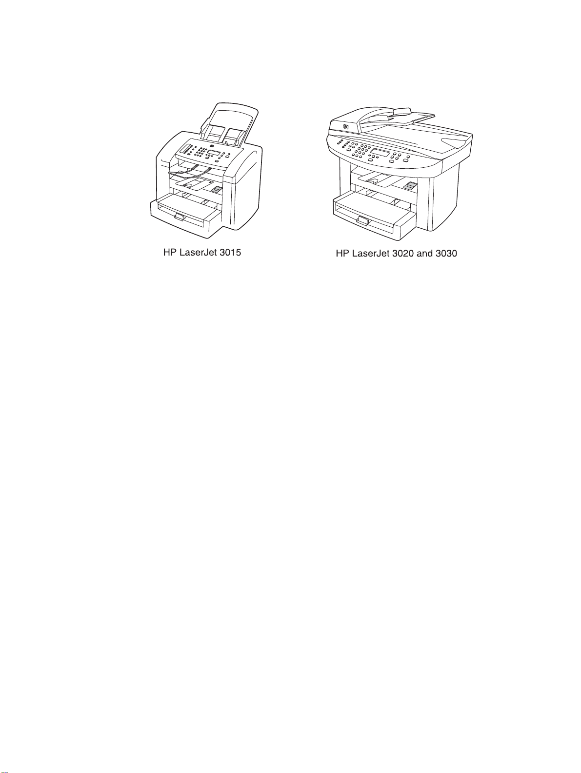
Figure 1-1. HP LaserJet 3015, 3020, and 3030 all-in-one products....................................2
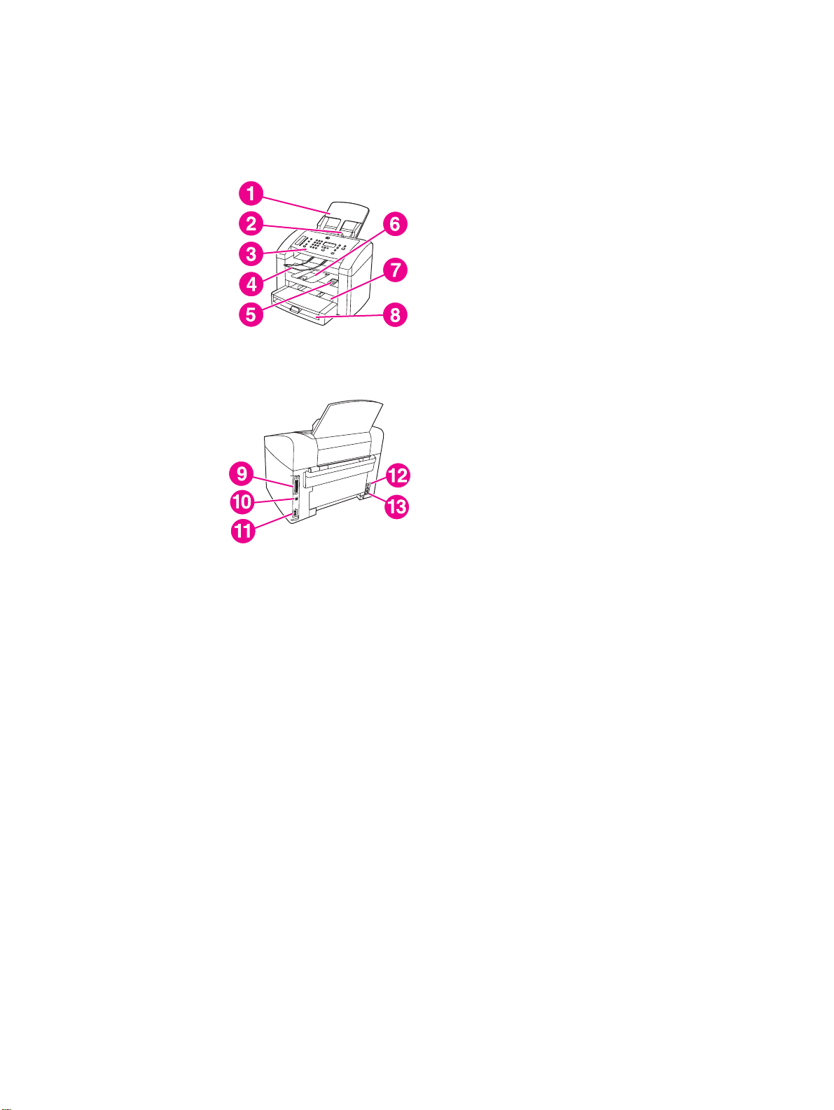
Figure 1-2. HP LaserJet 3015 all-in-one hardware components..........................................5
Figure 1-3. HP LaserJet 3020 all-in-one hardware components..........................................6
Figure 1-4. HP LaserJet 3030 all-in-one hardware components..........................................6
Figure 1-5. Sample Identification label (on the back of the product)....................................7
Figure 1-6. Location of additional serial number label.........................................................7
Figure 2-1. HP LaserJet 3015 dimensions.........................................................................30
Figure 2-2. HP LaserJet 3020/3030 dimensions................................................................30
Figure 2-3. HP LaserJet 3015 all-in-one control panel.......................................................31
Figure 2-4. HP LaserJet 3020 all-in-one control panel.......................................................32
Figure 2-5. HP LaserJet 3030 all-in-one control panel.......................................................32
Figure 2-6. Envelope construction......................................................................................41
Figure 2-7. Loading the LJ 3015 ADF (1 of 3)....................................................................44
Figure 2-8. Loading the LJ 3015 ADF (2 of 3)....................................................................45
Figure 2-9. Loading the LJ 3015 ADF (3 of 3)....................................................................45
Figure 2-10. Loading the LJ 3020 and 3030 ADF (1 of 2)....................................................46
Figure 2-11. Loading the LJ 3020 and 3030 ADF (2 of 2)....................................................46
Figure 2-12. Loading the LJ 3020 and 3030 flatbed scanner...............................................46
Figure 3-1. Cleaning the LJ 3015 glass..............................................................................51
Figure 3-2. Cleaning the LJ 3015 white platen...................................................................51
Figure 3-3. Cleaning the LJ 3020 and 3030 glass (1 of 2).................................................52
Figure 3-4. Cleaning the LJ 3020 and 3030 glass (2 of 2).................................................52
Figure 3-5. Cleaning the LJ 3020 and 3030 lid backing.....................................................52
Figure 3-6. Cleaning the print-cartridge area (1 of 3).........................................................54
Figure 3-7. Cleaning the print-cartridge area (2 of 3).........................................................54
Figure 3-8. Cleaning the print-cartridge area (3 of 3).........................................................55
Figure 3-9. Cleaning the separation pad............................................................................55
Figure 3-10. Cleaning the pickup roller (1 of 3)....................................................................55
Figure 3-11. Cleaning the pickup roller (2 of 3)....................................................................56
Figure 3-12. Cleaning the pickup roller (3 of 3)....................................................................56
Figure 3-13. Cleaning the separation pad (1 of 2)................................................................56
Figure 3-14. Cleaning the separation pad (2 of 2)................................................................56
Figure 3-15. Replacing the pickup roller (1 of 7)..................................................................57
Figure 3-16. Replacing the pickup roller (2 of 7)..................................................................57
Figure 3-17. Replacing the pickup roller (3 of 7)..................................................................57
Figure 3-18. Replacing the pickup roller (4 of 7)..................................................................58
Figure 3-19. Replacing the pickup roller (5 of 7)..................................................................58
Figure 3-20. Replacing the pickup roller (6 of 7) .................................................................58
Figure 3-21. Replacing the pickup roller (7 of 7) .................................................................58
Figure 3-22. Replacing the printer separation pad (1 of 5)..................................................59
Figure 3-23. Replacing the printer separation pad (2 of 5)..................................................59
Figure 3-24. Replacing the printer separation pad (3 of 5)..................................................60
Figure 3-25. Replacing the printer separation pad (4 of 5) .................................................60
Figure 3-26. Replacing the printer separation pad (5 of 5) .................................................60
Figure 3-27. Remove the media input tray (1 of 2)...............................................................61
Figure 3-28. Remove the paper pickup tray (2 of 2).............................................................61
ENWW xi
Page 15

Figure 3-29. Remove the separation pad.............................................................................62
Figure 3-30. Replacing the ADF input tray...........................................................................63
Figure 3-31. Replacing the ADF output bin..........................................................................63
Figure 3-32. Replacing the ADF pickup-roller assembly (1 of 9) ........................................63
Figure 3-33. Replacing the ADF pickup-roller assembly (2 of 9) ........................................64
Figure 3-34. Replacing the ADF pickup-roller assembly (3 of 9) ........................................64
Figure 3-35. Replacing the ADF pickup-roller assembly (4 of 9) ........................................64
Figure 3-36. Replacing the ADF pickup-roller assembly (5 of 9) ........................................64
Figure 3-37. Replacing the ADF pickup-roller assembly (6 of 9) ........................................65
Figure 3-38. Replacing the ADF pickup-roller assembly (7 of 9) ........................................65
Figure 3-39. Replacing the ADF pickup-roller assembly (8 of 9) ........................................65
Figure 3-40. Replacing the ADF pickup-roller assembly (9 of 9) ........................................65
Figure 3-41. Remove the separation pad.............................................................................66
Figure 3-42. Replacing the control-panel bezel (1 of 4).......................................................66
Figure 3-43. Replacing the control-panel bezel (2 of 4).......................................................67
Figure 3-44. Replacing the control-panel bezel (3 of 4).......................................................67
Figure 3-45. Replacing the control-panel bezel (4 of 4).......................................................67
Figure 4-1. Product configuration ......................................................................................70
Figure 4-2. HP LaserJet 3015, 3020, and 3030 printer (product base) timing
diagram .........................................................................................................74
Figure 4-3. Printer functional block diagram.......................................................................78
Figure 4-4. Laser/scanner operation..................................................................................80
Figure 4-5. High-voltage power supply circuit....................................................................82
Figure 4-6. Image-formation block diagram ......................................................................83
Figure 4-7. Printer paper path ...........................................................................................85
Figure 4-8. Basic operation block diagram.........................................................................87
Figure 4-9. HP LaserJet 3015 optical and feed systems...................................................88
Figure 4-10. HP LaserJet 3015 feed control (1 of 2)............................................................89
Figure 4-11. HP LaserJet 3015 feed control (2 of 2)............................................................90
Figure 4-12. HP LaserJet 3015 optical system (1 of 2)........................................................91
Figure 4-13. HP LaserJet 3015 optical system (2 of 2)........................................................92
Figure 4-14. HP LaserJet 3020 and 3030 optical system ...................................................93
Figure 4-15. HP LaserJet 3020 and 3030 ADF path ...........................................................95
Figure 5-1. HP LaserJet 3015, 3020, and 3030 products................................................104
Figure 5-2. Parts removal order for the HP LaserJet 3015 all-in-one..............................105
Figure 5-3. Parts removal order for the HP LaserJet 3020 and 3030 all-in-one .............105
Figure 5-4. Parts removal order for the printer (product base, all models)......................106
Figure 5-5. Parts removal order HP LaserJet 3015 scanner assembly...........................107
Figure 5-6. Remove the link assemblies and scanner support frame springs (1 of 4) ....108
Figure 5-7. Remove the link assemblies and scanner support frame springs (2 of 4).....108
Figure 5-8. Remove the link assemblies and scanner support frame springs (3 of 4).....109
Figure 5-9. Remove the link assemblies and scanner support frame springs (4 of 4).....109
Figure 5-10. Remove the scanner side covers (1 of 3)......................................................110
Figure 5-11. Remove the scanner side covers (2 of 3)......................................................110
Figure 5-12. Remove the scanner side covers (3 of 3)......................................................111
Figure 5-13. Remove the separation pad...........................................................................112
Figure 5-14. Remove the control-panel bezel (1 of 3)........................................................112
Figure 5-15. Remove the control-panel bezel (2 of 3)........................................................113
Figure 5-16. Remove the control-panel bezel (3 of 3)........................................................113
Figure 5-17. Remove the control-panel assembly (1 of 2).................................................114
Figure 5-18. Remove the control-panel assembly (2 of 2).................................................114
Figure 5-19. Remove the media lever and media lever torsion spring (1 of 2)..................115
Figure 5-20. Remove the media lever and media lever torsion spring (2 of 2)..................115
Figure 5-21. Remove the separation pad assembly (1 of 3)..............................................116
Figure 5-22. Remove the separation pad assembly (2 of 3)..............................................117
Figure 5-23. Remove the separation pad assembly (3 of 3)..............................................117
xii ENWW
Page 16

Figure 5-24. Remove the scanner assembly (1 of 15).......................................................118
Figure 5-25. Remove the scanner assembly (2 of 15).......................................................118
Figure 5-26. Remove the scanner assembly (3 of 15).......................................................119
Figure 5-27. Remove the scanner assembly (4 of 15).......................................................119
Figure 5-28. Remove the scanner assembly (5 of 15) ......................................................120
Figure 5-29. Remove the scanner assembly (6 of 15).......................................................120
Figure 5-30. Remove the scanner assembly (7 of 15).......................................................121
Figure 5-31. Remove the scanner assembly (8 of 15).......................................................121
Figure 5-32. Remove the scanner assembly (9 of 15).......................................................122
Figure 5-33. Remove the scanner assembly (10 of 15).....................................................122
Figure 5-34. Remove the scanner assembly (11 of 15) ....................................................123
Figure 5-35. Remove the scanner assembly (12 of 15) ....................................................124
Figure 5-36. Remove the scanner assembly (13 of 15).....................................................125
Figure 5-37. Remove the scanner assembly (14 of 15).....................................................125
Figure 5-38. Remove the scanner assembly (15 of 15).....................................................126
Figure 5-39. Remove the scanner assembly top cover (1 of 4).........................................127
Figure 5-40. Remove the scanner assembly top cover (2 of 4).........................................127
Figure 5-41. Remove the scanner assembly top cover (3 of 4).........................................128
Figure 5-42. Remove the scanner assembly top cover (4 of 4) ........................................128
Figure 5-43. Reinstalling the scanner assembly top cover................................................129
Figure 5-44. Align the scanner assembly top cover and base...........................................129
Figure 5-45. Remove the top-cover assembly (1 of 2).......................................................130
Figure 5-46. Remove the top-cover assembly (2 of 2) ......................................................130
Figure 5-47. Remove the pickup roller (1 of 2)...................................................................131
Figure 5-48. Remove the pickup roller (2 of 2)...................................................................131
Figure 5-49. Remove the white platen (1 of 2)...................................................................132
Figure 5-50. Remove the white platen (2 of 2) ..................................................................132
Figure 5-51. Parts removal order HP LaserJet 3020 and 3030 scanner assembly...........133
Figure 5-52. Remove the ADF input tray............................................................................133
Figure 5-53. Remove the flatbed lid (1 of 5) ......................................................................134
Figure 5-54. ADF cover correctly installed.........................................................................134
Figure 5-55. Remove the flatbed lid (2 of 5).......................................................................135
Figure 5-56. Remove the flatbed lid (3 of 5).......................................................................135
Figure 5-57. Remove the flatbed lid (4 of 5).......................................................................136
Figure 5-58. Remove the flatbed lid (5 of 5).......................................................................136
Figure 5-59. Remove the link assemblies and scanner support frame springs (1 of 4).....137
Figure 5-60. Remove the link assemblies and scanner support frame springs (2 of 4).....137
Figure 5-61. Remove the link assemblies and scanner support frame springs (3 of 4).....138
Figure 5-62. Remove the link assemblies and scanner support frame springs (4 of 4).....138
Figure 5-63. Remove the control-panel bezel ...................................................................139
Figure 5-64. Remove the control panel assembly (1 of 2).................................................139
Figure 5-65. Remove the control panel assembly (2 of 2) ................................................140
Figure 5-66. Remove the separation pad...........................................................................140
Figure 5-67. Remove the ADF input-tray flag.....................................................................141
Figure 5-68. Correct positioning of the ADF input-tray spring ...........................................141
Figure 5-69. Remove the ADF pickup roller (1 of 2)..........................................................142
Figure 5-70. Remove the ADF pickup roller (2 of 2)..........................................................142
Figure 5-71. Remove the ADF scanner glass (1 of 3)........................................................143
Figure 5-72. Remove the ADF scanner glass (2 of 3)........................................................143
Figure 5-73. Remove the ADF scanner glass (3 of 3)........................................................144
Figure 5-74. Install the ADF scanner glass........................................................................144
Figure 5-75. Remove the scanner assembly (1 of 13).......................................................145
Figure 5-76. Remove the scanner assembly (2 of 13) ......................................................145
Figure 5-77. Remove the scanner assembly (3 of 13).......................................................146
Figure 5-78. Remove the scanner assembly (4 of 13).......................................................146
Figure 5-79. Remove the scanner assembly (5 of 13).......................................................147
ENWW xiii
Page 17

Figure 5-80. Remove the scanner assembly (6 of 13).......................................................147
Figure 5-81. Remove the scanner assembly (7 of 13).......................................................148
Figure 5-82. Remove the scanner assembly (8 of 13).......................................................148
Figure 5-83. Remove the scanner assembly (9 of 13).......................................................149
Figure 5-84. Remove the scanner assembly (10 of 13) ....................................................150
Figure 5-85. Remove the scanner assembly (11 of 13) ....................................................151
Figure 5-86. Remove the scanner assembly (12 of 13).....................................................151
Figure 5-87. Remove the scanner assembly (13 of 13).....................................................152
Figure 5-88. Parts removal order for the printer (product base, all models)......................153
Figure 5-89. Remove the printer separation pad (1 of 2)...................................................154
Figure 5-90. Remove the printer separation pad (2 of 2)...................................................154
Figure 5-91. Remove the print cartridge (1 of 2)................................................................155
Figure 5-92. Remove the print cartridge (2 of 2)................................................................155
Figure 5-93. Remove the printer pickup roller (1 of 5).......................................................156
Figure 5-94. Remove the printer pickup roller (2 of 5).......................................................156
Figure 5-95. Remove the printer pickup roller (3 of 5).......................................................157
Figure 5-96. Remove the printer pickup roller (4 of 5).......................................................157
Figure 5-97. Remove the printer pickup roller (5 of 5).......................................................158
Figure 5-98. Remove the media input tray (1 of 3).............................................................158
Figure 5-99. Remove the media input tray (2 of 3).............................................................159
Figure 5-100. Remove the media input tray (3 of 3).............................................................159
Figure 5-101. Remove the transfer roller (1 of 3).................................................................160
Figure 5-102. Remove the transfer roller (2 of 3).................................................................160
Figure 5-103. Remove the transfer roller (3 of 3).................................................................161
Figure 5-104. Remove the printer side covers (1 of 3).........................................................161
Figure 5-105. Remove the printer side covers (2 of 3) ........................................................162
Figure 5-106. Remove the printer side covers (2 of 3) ........................................................162
Figure 5-107. Remove the printer side covers (3 of 3).........................................................163
Figure 5-108. Remove the print-cartridge door (1 of 2)........................................................163
Figure 5-109. Remove the print-cartridge door (2 of 2)........................................................164
Figure 5-110. Remove the rear cover and fuser cover (1 of 3)............................................164
Figure 5-111. Remove the rear cover and fuser cover (2 of 3)............................................165
Figure 5-112. Remove the rear cover and fuser cover (3 of 3)............................................165
Figure 5-113. Remove the front cover (1 of 3).....................................................................166
Figure 5-114. Remove the front cover (2 of 3).....................................................................166
Figure 5-115. Remove the front cover (3 of 3).....................................................................167
Figure 5-116. Front-cover locking tabs.................................................................................167
Figure 5-117. Installing the scanner cushions......................................................................168
Figure 5-118. Remove the speaker assembly (1 of 2).........................................................168
Figure 5-119. Remove the speaker assembly (2 of 2).........................................................169
Figure 5-120. Remove the power supply (1 of 3).................................................................170
Figure 5-121. Remove the power supply (2 of 3).................................................................170
Figure 5-122. Remove the power supply (3 of 3).................................................................171
Figure 5-123. Correct routing of the power-supply wire-harnesses.....................................171
Figure 5-124. HP LaserJet 3015 formatter and LIU.............................................................173
Figure 5-125. HP LaserJet 3020 formatter without LIU........................................................173
Figure 5-126. HP LaserJet 3030 formatter and LIU.............................................................173
Figure 5-127. Remove the formatter (1 of 2) (and LIU installed).........................................174
Figure 5-128. Remove the formatter (2 of 2)........................................................................174
Figure 5-129. Remove the scanner support frame (1 of 3)..................................................175
Figure 5-130. Remove the scanner support frame (2 of 3)..................................................176
Figure 5-131. Remove the scanner support frame (3 of 3)..................................................176
Figure 5-132. Remove the chassis reinforcement plate.......................................................177
Figure 5-133. Remove the ECU (1 of 6)...............................................................................178
Figure 5-134. Remove the ECU (2 of 6)...............................................................................178
Figure 5-135. Remove the ECU (3 of 6)...............................................................................179
xiv ENWW
Page 18

Figure 5-136. Remove the ECU (4 of 6)...............................................................................179
Figure 5-137. Remove the ECU (5 of 6)...............................................................................180
Figure 5-138. Remove the ECU (6 of 6)...............................................................................180
Figure 5-139. Laser/scanner assembly shutter arm.............................................................181
Figure 5-140. Remove the laser/scanner assembly.............................................................182
Figure 5-141. Remove the main motor (1 of 2)....................................................................183
Figure 5-142. Remove the main motor (2 of 2) ...................................................................183
Figure 5-143. Remove the fuser assembly (1 of 2)..............................................................184
Figure 5-144. Remove the fuser assembly (2 of 2)..............................................................185
Figure 5-145. Fragile tab on fuser assembly........................................................................185
Figure 5-146. Remove the paper-pickup assembly..............................................................186
Figure 6-1. Repetitive image defect ruler ........................................................................222
Figure 6-2. Clear a jam in the product base (1 of 3)........................................................223
Figure 6-3. Clear a jam in the product base (2 of 3)........................................................224
Figure 6-4. Clear a jam in the product base (3 of 3)........................................................224
Figure 6-5. Clearing output bin jams (HP LJ 3015) .........................................................225
Figure 6-6. Clearing ADF output bin jams (HP LaserJet 3015) ......................................225
Figure 6-7. Clearing output bin jams (HP LaserJet 3020 and 3030) ...............................225
Figure 6-8. ADF lid open (HP LaserJet 3015)..................................................................228
Figure 6-9. ADF lid open (HP LaserJet 3020 and 3030)..................................................228
Figure 6-10. Clear an ADF jam (HP LaserJet 3015)..........................................................229
Figure 6-11. Clear an ADF jam (HP LaserJet 3020 and 3030; 1 of 2)...............................229
Figure 6-12. Clear an ADF jam (HP LaserJet 3020 and 3030; 2 of 2)...............................229
Figure 6-13. Check the fuser connectors on the fuser.......................................................237
Figure 6-14. Check the fuser connectors on the power supply..........................................237
Figure 6-15. Print-cartridge high-voltage contacts ............................................................238
Figure 6-16. High-voltage contacts ....................................................................................239
Figure 6-17. Example of a T.30 trace of a successfully sent fax ......................................260
Figure 6-18. Example of a T.30 trace of a successfully received fax ................................261
Figure 6-19. Main wiring, HP LaserJet 3015 scanner assembly .......................................269
Figure 6-20. Main wiring, HP LaserJet 3020 and 3030 scanner assembly ......................270
Figure 6-21. Main wiring, HP LaserJet 3015, 3020,and 3030 product base......................271
Figure 6-22. Major components..........................................................................................272
Figure 6-23. Main parts.......................................................................................................273
Figure 6-24. Sensors and motors ......................................................................................274
Figure 6-25. PCBs..............................................................................................................275
Figure 6-26. HP LaserJet 3020 and 3030 components.....................................................276
Figure 6-27. Major components..........................................................................................277
Figure 6-28. Solenoid, sensors, switches, and motor........................................................278
Figure 6-29. PCBs..............................................................................................................279
Figure 7-1. HP LaserJet 3015 .........................................................................................286
Figure 7-2. ADF input and delivery assemblies (HP LaserJet 3015)...............................288
Figure 7-3. Internal components (HP LaserJet 3015) .....................................................290
Figure 7-4. Frame assembly (HP LaserJet 3015)............................................................292
Figure 7-5. Guide assembly (HP LaserJet 3015).............................................................294
Figure 7-6. HP LaserJet 3020/3030 scanner assembly ..................................................296
Figure 7-7. Link assembly (HP LaserJet 3020/3030) ......................................................298
Figure 7-8. Major assemblies (HP LaserJet 3020/3030) .................................................300
Figure 7-9. HP LaserJet 3015/3020/3030 printer base....................................................304
Figure 7-10. Pickup and delivery tray assemblies (LJ 3015/3020/3030 printer base).......306
Figure 7-11. External covers (LJ 3015/3020/3030 printer base)........................................308
Figure 7-12. Internal components 1 of 1 (LJ 3015/3020/3030 printer base)......................310
Figure 7-13. Internal components 2 of 2 (LJ 3015/3020/3030 printer base)......................312
Figure 7-14. Internal components 3 of 3 (LJ 3015/3020/3030 printer base)......................314
Figure 7-15. Paper-pickup assembly (LJ 3015/3020/3030 printer base)...........................316
Figure 7-16. Fuser (fixing assy) assembly (LJ 3015/3020/3030 printer base)...................318
ENWW xv
Page 19

xvi ENWW
Page 20

1
Product Information
This chapter provides information about the following topics.
Product configurations...............................................................................................................2
HP LaserJet 3015, 3020, and 3030 all-in-one products......................................................2
HP LaserJet 3015 all-in-one product...................................................................................3
HP LaserJet 3020/3030 all-in-one product..........................................................................3
Product features ........................................................................................................................4
Overview of products.................................................................................................................5
Hardware components........................................................................................................5
Product identification..................................................................................................................7
Model and serial numbers...................................................................................................7
Product specifications................................................................................................................8
Physical specifications.........................................................................................................8
Environmental specifications (all models)...........................................................................8
HP LaserJet 3015 performance specifications....................................................................8
HP LaserJet 3020/3030 performance specifications.........................................................10
Electrical specifications (all models)..................................................................................12
Acoustic emissions (all models)........................................................................................12
Skew specifications (all models).......................................................................................12
HP LaserJet 3030 fax capabilities.....................................................................................13
HP LaserJet 3015, 3020, and 3030 all-in-one battery.......................................................14
Warranty statement..................................................................................................................15
HP’s Premium Protection print-cartridge warranty...................................................................16
Extended warranty...................................................................................................................17
Print-cartridge information .......................................................................................................18
Refilled print cartridges ....................................................................................................18
HP LaserJet printing supplies ...........................................................................................18
HP Printing Supplies Returns and Recycling Program information..................................18
FCC regulations.......................................................................................................................20
Telephone Consumer Protection Act (United States)..............................................................22
IC CS-03 requirements............................................................................................................23
Declaration of Conformity ........................................................................................................24
Safety statements....................................................................................................................25
Laser safety statement......................................................................................................25
Canada DOC regulations..................................................................................................25
Laser statement for Finland...............................................................................................26
Korean EMI statement.......................................................................................................26
Australian EMC requirements............................................................................................26
Regulatory information for the European Union countries/regions .........................................27
ENWW 1
Page 21
Product configurations
HP LaserJet 3015, 3020, and 3030 all-in-one products
Figure 1-1.
HP LaserJet 3015, 3020, and 3030 all-in-one products
● Prints up to 15 pages per minute (less than a 10-second wait for the first page to print)
● 150-sheet printer input tray with a 10-page priority input tray
● 600 by 600 dpi printing using Resolution Enhancement technology (REt)
● 2,000-page print cartridge (using an average of 5 percent toner coverage on printed A4-
or letter-size pages)
●
4 MB of ROM, 32 MB of RAM
●
Universal serial bus (USB) port
● 1284-B compliant parallel port
●
V.34 fax modem that supports speeds up to 33.6 kbps (HP LaserJet 3015 and 3030 only)
● Two RJ-11 ports (one line and one accessory port)
● Two-line LCD display (16 characters per line)
● Additional 2 MB flash ROM for fax storage (up to 110 pages based on a slerexe test
page) (HP LaserJet 3015 and 3030 only)
● Expandable input/output (I/O) using the HP Jetdirect 10/100Base-TX
● Individual speed-dial memory and group speed-dial memory (120 entries using the
Toolbox) (HP LaserJet 3015 and 3030 only)
2 Chapter 1 Product Information ENWW
Page 22

●
Supported software
● HP Toolbox
● HP LaserJet Scan
● TWAIN or WIA Scan Driver
● HP LaserJet Fax
● Readiris OCR (not installed with other software; separate installation is required)
●
Printer drivers (PCL 5e, PCL 6, and PS
● Installer/unistaller
●
Supported operating systems
● Windows 98Se (second edition)
● Windows Millennium Edition (Me)
● Windows 2000
● Windows XP (32-bit)
● Mac OS 9.1 or 9.2.x
● Mac OS X (10.2.x only)
Note
Note
Driver-only support for Windows 98 (first edition), Windows XP 64-bit, and Windows 2003
Server.
HP LaserJet 3015 all-in-one product
●
Contact image scanner (CIS) 600 ppi, 24-bit color scanner
● 30-sheet automatic document feeder (ADF) feeds pages at up to 12 pages per minute
(ppm)
● Three status LEDs, a numeric keypad, and menu navigation buttons on the control panel
● Selectable single- or multiple-sheet lever for the ADF
HP LaserJet 3020/3030 all-in-one product
● Coupled charged device (CCD) 600 ppi 24-bit color scanner
● Letter/A4-sized flatbed scanner glass
● 50-sheet automatic document feeder (ADF) feeds pages at up to 12 pages per minute
(ppm)
● Status LEDs, a numeric keypad, and menu navigation buttons on the control panel (the HP
LaserJet 3020 has two status LEDs; the HP LaserJet 3030 has three status LEDs)
The HP LaserJet 3020 does not have fax capabilities.
ENWW Product configurations 3
Page 23

Product features
The HP LaserJet 3015, 3020, and 3030 all-in-one products are designed to perform the
following tasks:
● Print: Print documents with HP LaserJet quality.
● Copy: Make up to 99 laser-quality copies of a 50-page original. It also enlarges, reduces,
and lightens/darkens copies. (The HP LaserJet 3020 and 3030 also collate copies.)
● Scan: Scan documents to create electronic text or graphics files.
● Fax: Send and receive documents by using standard fax communications (HP LaserJet
3015 and 3030 only).
4 Chapter 1 Product Information ENWW
Page 24
Overview of products
Hardware components
Use the following illustrations to identify the hardware components.
Figure 1-2.
Figure 1-2.
HP LaserJet 3015 all-in-one hardware components (1 of 2)
HP LaserJet 3015 all-in-one hardware components (2 of 2)
1 Automatic document feeder (ADF) input tray
2
ADF media lever
3 Control panel
4 ADF output bin
5 Print-cartridge-door release
6
Output bin
7 Priority input slot
8 Media input tray
9 Parallel port
10 USB port
11 Fax interface ports
12 Power switch
13 Power receptacle
ENWW Overview of products 5
Page 25
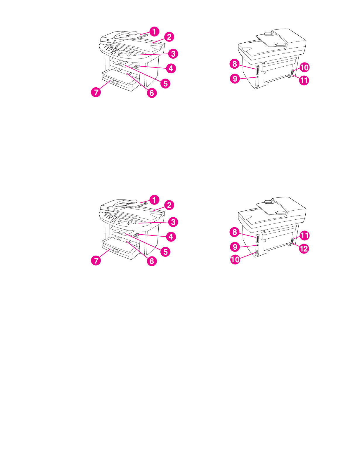
Figure 1-3. HP LaserJet 3020 all-in-one hardware components
1 Automatic document feeder (ADF) input tray
2 Flatbed scanner lid and ADF output bin
3 Control panel
4 Print-cartridge-door release
5 Output bin
6 Priority input tray
7 Media input tray
8 Parallel port
9 USB port
10 Power switch
11 Power receptacle
Figure 1-4. HP LaserJet 3030 all-in-one hardware components
1 Automatic document feeder (ADF) input tray
2 Flatbed scanner lid and ADF output bin
3 Control panel
4 Print-cartridge-door release
5 Output bin
6 Priority input tray
7 Media input tray
8 Parallel port
9 USB port
10 Fax interface ports
11 Power switch
12 Power receptacle
6 Chapter 1 Product Information ENWW
Page 26
Product identification
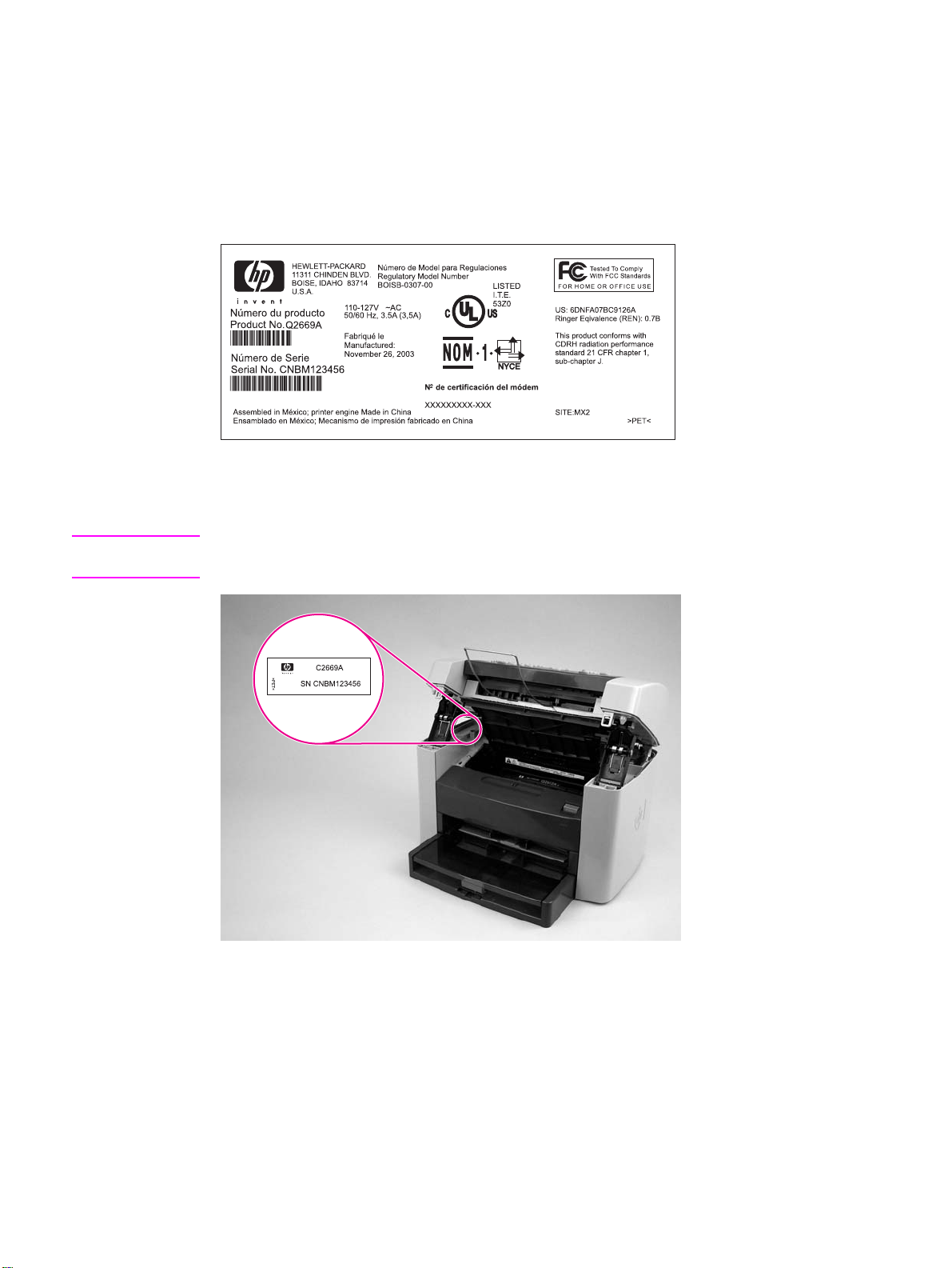
Model and serial numbers
An identification label is located on the back of the product. This label contains the model and
serial numbers. The serial number contains information about the country/region of origin,
revision level, production code, and production number of the product. The label also contains
power-rating and regulatory information.
Figure 1-5. Sample Identification label (on the back of the product)
An additional identification label is located on the top-left side of the scanner support frame.
Open the print cartridge door to find this label.
Note
Figure 1-6. Location of additional serial number label
The additional serial number label is in the same location on the scanner support frame for all
of the HP LaserJet 3015, 3020, and 3030 all-in-one products.
ENWW Product identification 7
Page 27

Product specifications
Physical specifications
Table 1-1. Physical specifications
Product Height Depth Width Weight
HP LaserJet 3015
product
HP LaserJet
3020/3030
product
445 mm
(17.5 inches)
556 mm
21.89 inches)
440 mm
(17.3 inches)
483 mm
(19.02 inches)
430 mm
(16.9 inches)
497 mm
(19.6 inches)
Environmental specifications (all models)
Table 1-2. Environmental specifications (all models)
Category Specification
Operating environment (unit plugged into an ac
outlet)
Storage environment (unit not plugged into an ac
outlet)
● Temperature: 15° to 32.5° C ( 59° to 90.5° F)
● Humidity: 10 percent to 80 percent relative
humidity (no condensation)
● Temperature: -20° to 40° C (-4° to 104° F)
● Humidity: Less than 95 percent relative
humidity (with no condensation)
9.1 kg
(20 pounds)
11.34 kg
(25 pounds)
HP LaserJet 3015 performance specifications
Table 1-3. HP LaserJet 3015 performance specifications
Category Specification
Printer capacities and ratings
Print speed
Media input tray capacity
Priority input slot capacity
Output bin capacity
Minimum paper size
8 Chapter 1 Product Information ENWW
● 15 pages per minute (ppm) for letter size paper and 14 ppm for
A4-size paper
● First page out in less than 10 seconds
150 sheets of regular-weight 60-g/m2 (16-lb) paper or up to 30
envelopes
10 sheets of regular-weight 75-g/m2 (20-lb) paper or 1 envelope
Up to 125 sheets of regular-weight 16-lb (60-g/m2) paper
76 by 127 mm (3 by 5 inches)
Page 28

Table 1-3. HP LaserJet 3015 performance specifications (continued)
Category Specification
Maximum paper size
216 by 356 mm (8.5 by 14 inches). The output bin holds one sheet
of legal-size media 215 by 356 mm (8.5 by 14 inches). Subsequent
sheets of legal-size media slide off of the output bin.
Media weight
Media input tray: 60- to 163-g/m2 (16- to 43-lb) cut sheet paper
2
Priority input slot: 60- to 90-g/m
(16- to 24-lb) single thickness
envelopes
Print paper output: 135- to 176-g/m
Base memory
4 MB of ROM and 32 MB of RAM (9 MB for the product and 23 MB
available to the user)
Print resolution
Duty cycle
1,200 dpi
● 7,000 single-sided pages per month (maximum)
● 800 single-sided pages per month (average)
PCL (Printer Control Language) Level 5e and 6
PostScript® (PS) Emulates Adobe® PostScript level 2
Copier capacities and ratings
Copy speed
Up to 15 ppm
Multiple copies Up to 99 per job
2
(36- to 47-lb) postcards
Copy reduction or enlargement
Acoustic emissions (per ISO
25 percent to 400 percent
6.3 Bel sound power level
9296) while copying
Scanner capacities and ratings
Margins for scanned items
3.05 mm (0.12 inch) right and left
4.23 mm (0.17 inch) top and bottom
Scanner duty cycle
Scan resolution
2,000 single-sided items per month
600 dpi color
Automatic document feeder (ADF) input tray specifications
Input capacity
Media weight (input and output)
Up to 30 sheets of flat 60- to 75-g/m2 (16- to 20-lb) media
Single sheet setting ( blue media lever set to the right): 42- to 260-
2
(11- to 69-lb)
g/m
Multiple sheet setting ( blue media lever set to the left): 46- to 105-
2
g/m
(12- to 28-lb)
Media size 74 by 105 mm (2.9 by 4.1 inches) to 216 mm by 381 mm (8.5 by 15
inches). The ADF output bin holds one sheet of legal-size media
215 by 356 mm (8.5 by 14 inches). Subsequent sheets of legal-size
media slide off of the ADF output bin.
Speed Up to 12 ppm for letter-size or A4-size media
Duty cycle
1,000 pages per month
Port availability
ENWW Product specifications 9
Page 29

Table 1-3. HP LaserJet 3015 performance specifications (continued)
Category Specification
USB
Parallel
Fax capabilities and ratings
Fax transmission speed
Right/left margins for printed
pages
Top/bottom margins for printed
pages
Fax compatibility ITU Group 3; ECM
Fax coding schemes MH, MR, and MMR
Modem speed
Speed dialing Yes
Distinctive ring detect Yes
Fax resolution (standard)
Fax resolution (fine) 203 by 196 dpi
Compatible with USB 2.0 specification
● IEEE 1284-B level 2 device with an IEEE 1284-B receptacle
● Set the host computer to ECP (enhanced capabilities mode)
3 seconds per page (ITU-T Test Image #1)
6.3 mm (0.25 inch)
5.08 mm (0.2 inch)
Up to 33,600 bits per second (bps)
203 by 98 dpi
Fax resolution (superfine) 300 by 300 dpi (no halftone)
Fax resolution (photo) 300 by 300 dpi (halftone enabled)
Fax page storage Up to 110 slerexe pages
HP LaserJet 3020/3030 performance specifications
Table 1-4. HP LaserJet 3020/3030 performance specifications
Category Specification
Printer capacities and ratings
Print speed
Media input tray capacity
Priority input tray capacity
Output bin capacity
● 15 pages per minute (ppm) for letter-size paper and 14 ppm for
A4-size paper
● First page out in less than 9 seconds
150 sheets of regular-weight 60-g/m2 (16-lb) paper or up to 30
envelopes
10 sheets of regular-weight 75-g/m2 (20-lb) paper or 1 envelope
Up to 125 sheets of regular-weight 75-g/m2 (20-lb) paper
Minimum paper size
Maximum paper size
76 by 127 mm (3 by 5 inches)
216 by 356 mm (8.5 by 14 inches)
10 Chapter 1 Product Information ENWW
Page 30

Table 1-4. HP LaserJet 3020/3030 performance specifications (continued)
Category Specification
Media weight
Media input tray: 60- to 163-g/m2 (16- to 43-lb) cut sheet paper
2
Priority input slot: 60- to 90-g/m
(16- to 24-lb) single thickness
envelopes
Print paper output: 135- to 176-g/m
Base memory
4 MB of ROM and 32 MB of RAM (9 MB for the product and 23 MB
available to the user)
Print resolution
Duty cycle
1,200 dpi
● 7,000 single-sided pages per month (maximum)
● 1,000 single-sided pages per month (average)
PCL (Printer Control Language) Level 5e and 6
PostScript (PS) Emulates Adobe PostScript level 2
Copier capacities and ratings
Copy speed
Up to 15 ppm
Multiple copies Up to 99 per job
Copy reduction or enlargement
Acoustic emissions (per ISO
25 percent to 400 percent
6.3 Bel sound power level
9296) while copying
2
(36- to 47-lb) postcards
Scanner capacities and ratings
Margins for scanned items
3.05 mm (0.12 inch) right and left
4.06 mm (0.16 inch) top and bottom
Media size (216 by 356 mm) (8.5 by 11.7 inches) no minimum size
Scanner duty cycle
Scan resolution
2,000 single-sided items per month
600 dpi color
Automatic document feeder (ADF) input tray specifications
Input capacity
Media weight (input and output)
Up to 50 sheets of flat 60 to 75-g/m2 (16- to 20-lb) media
60- to 90-g/m2 (16- to 24-lb)
Media size 127 by 127 mm (5 by 5 inches) to 216 by 381 mm (8.5 by 15
inches)
Speed Up to 15 ppm for letter-size or A4-size media
Duty cycle
1,000 pages per month
Port availability
USB
Parallel
Compatible with USB 2.0 specification
● IEEE 1284-B level 2 device with an IEEE 1284-B receptacle
● Set the host computer to ECP (enhanced capabilities mode)
ENWW Product specifications 11
Page 31

Electrical specifications (all models)
Note
The values are subject to change. See http://www.hp.com/support/lj3015 or
http://www.hp.com/support/lj3030 for the most current information. The 110-volt and 220-volt
power sources are not interchangeable.
Table 1-5. Electrical specifications (all models)
Item 110-volt models 220-volt models
Power supply 110 to 127 V (± 10%)
50 to 60 Hz (± 2 Hz)
Power consumption (typical)
Printing
Standby
Power Save
Off
Minimum recommended circuit
capacity
300 W (average)
14 W (average)
14 W (average)
0 W
4.5 A 2.3 A
220 to 240 V (± 10%)
50 to 60 Hz (± 2 Hz)
300 W (average)
14 W (average)
14 W (average)
0 W
Acoustic emissions (all models)
Note
The values are subject to change. See http://www.hp.com/support/lj3015 or
http://www.hp.com/support/lj3030 for the most current information. During other operations,
acoustic emissions can vary.
Table 1-6. Acoustic emissions (all models)
Activity
level
Active LpAm56 dB (A) LpAm48 dB (A) LWAd6.1 Bels dB (A)
Idle inaudible inaudible inaudible
Operator (<1m) Bystander (1m) Sound power
Skew specifications (all models)
Table 1-7. Skew specifications (all models)
Category Specification
Skew: all vertical lines are
parallel to the left edge of the
media.
3.0 mm (0.12 inch) over 250 mm (9.85 inches) length (0.8 percent)
for cut-sheet media (except for A5 size)
3.3 mm (.13 inch) over 220 mm (8.66 inches) length (1.5 percent)
for envelopes, postcards, and A5 size cut-sheet media.
1.65 mm (0.06 inch) over 190 mm (7.48 inches) width for cut-sheet
media (leading-edge skew)
12 Chapter 1 Product Information ENWW
Page 32

Table 1-7. Skew specifications (all models) (continued)
Category Specification
First line/leading edge skew:
the distance of the first scan line
from the leading edge of the
media.
Left margin: the distance of the
left-most vertical line (first two
dots of each scan line) from the
left edge of the media.
Parallelism All vertical lines must be parallel within an absolute value of 2
4.23 mm (0.16 inch) ± 2.0 mm (0.07 inch) for cut-sheet media.
4.23 mm (0.16 inch) ± 2.5 mm (0.09 inch) for thick media over
105-g/m
15.0 mm (0.59 inch) ± 3.5 mm (0.13 inch) for envelopes and
postcards.
4.23 mm (0.16 inch) ± 2.0 mm (0.07 inch) for cut-sheet media.
15.0 mm (0.59 inch) ± 3.5 mm (0.13 inch) for envelopes and
postcards.
percent (1.5 mm [0.05 inch] over a 250 mm [9.85 inch] length for
cut-sheet media).
2
(28 pounds).
HP LaserJet 3030 fax capabilities
Table 1-8. HP LaserJet 3030 fax capabilities
Category Specification
Fax transmission speed
Right/left margins for printed
pages
3 seconds/page (ITU-T Test Image #1)
6.3 mm (0.25 inch)
Top/bottom margins for printed
pages
Fax compatibility ITU Group 3; ECM
Fax coding schemes MH, MR, and MMR
Modem speed
Speed dialing Yes
Distinctive ring detect Yes
Fax resolution (standard)
Fax resolution (fine) 203 by 196 dpi
Fax resolution (superfine) 300 by 300 dpi (no halftone)
Fax resolution (photo) 300 by 300 dpi (halftone enabled)
Fax page storage Up to 110 slerexe pages
5.08 mm (0.2 inch)
Up to 33,600 bits per second (bps)
203 by 98 dpi
ENWW Product specifications 13
Page 33

HP LaserJet 3015, 3020, and 3030 all-in-one battery
Table 1-9. HP LaserJet 3015, 3020, and 3030 all-in-one battery
Category Specification
Battery material Polycarbon Monoflouride Lithium
Battery type Button or coin cell battery
Note
The battery is permanently attached to the formatter and cannot be
removed or replaced.
Quantity per device 1
Weight Approximately 1 gram (0.04 ounce)
Lithium type Solid
Battery manufacturers Rayovac of Madison, Wisconsin, USA; and Panasonic of Secaucus,
New Jersey, USA
14 Chapter 1 Product Information ENWW
Page 34

Warranty statement
HP PRODUCT
HP LaserJet 3015/3020/3030 printers
HP warrants to you, the end-user customer, that HP hardware, accessories, and supplies will be free from defects
in materials and workmanship after the date of purchase, for the period specified above. If HP receives notice of
such defects during the warranty period, HP will, at its option, either repair or replace products which prove to be
defective. Replacement products may be either new or equivalent in performance to new.
HP warrants to you that HP software will not fail to execute its programming instructions after the date of purchase,
for the period specified above, due to defects in material and workmanship when properly installed and used. If HP
receives notice of such defects during the warranty period, HP will replace software which does not execute its
programming instructions due to such defects.
HP does not warrant that the operation of HP products will be uninterrupted or error free. If HP is unable, within a
reasonable time, to repair or replace any product to a condition as warranted, you will be entitled to a refund of the
purchase price upon prompt return of the product.
HP products may contain remanufactured parts equivalent to new in performance or may have been subject to
incidental use.
Warranty does not apply to defects resulting from (a) improper or inadequate maintenance or calibration, (b)
software, interfacing, parts, or supplies not supplied by HP, (c) unauthorized modification or misuse, (d) operation
outside of the published environmental specifications for the product, or (e) improper site preparation or
maintenance.TO THE EXTENT ALLOWED BY LOCAL LAW, THE ABOVE WARRANTIES ARE EXCLUSIVE AND
NO OTHER WARRANTY OR CONDITION, WHETHER WRITTEN OR ORAL, IS EXPRESSED OR IMPLIED AND
HP SPECIFICALLY DISCLAIMS ANY IMPLIED WARRANTIES OR CONDITIONS OF MERCHANTABILITY,
SATISFACTORY QUALITY, AND FITNESS FOR A PARTICULAR PURPOSE. Some countries/regions, states, or
provinces do not allow limitations on the duration of an implied warranty, so the above limitation or exclusion might
not apply to you. This warranty gives you specific legal rights and you might also have other rights that vary from
country/region to country/region, state to state, or province to province.
HP’s limited warranty is valid in any country/region or locality where HP has a support presence for this product and
where HP has marketed this product. The level of warranty service you receive may vary according to local
standards. HP will not alter form, fit, or function of the product to make it operate in a country/region for which it
was never intended to function for legal or regulatory reasons.TO THE EXTENT ALLOWED BY LOCAL LAW, THE
REMEDIES IN THIS WARRANTY STATEMENT ARE YOUR SOLE AND EXCLUSIVE REMEDIES. EXCEPT AS
INDICATED ABOVE, IN NO EVENT WILL HP OR ITS SUPPLIERS BE LIABLE FOR LOSS OF DATA OR FOR
DIRECT, SPECIAL, INCIDENTAL, CONSEQUENTIAL (INCLUDING LOST PROFIT OR DATA), OR OTHER
DAMAGE, WHETHER BASED IN CONTRACT, TORT, OR OTHERWISE. Some countries/regions, states, or
provinces do not allow the exclusion or limitation of incidental or consequential damages, so the above limitation or
exclusion may not apply to you.THE WARRANTY TERMS CONTAINED IN THIS STATEMENT, EXCEPT TO THE
EXTENT LAWFULLY PERMITTED, DO NOT EXCLUDE, RESTRICT, OR MODIFY AND ARE IN ADDITION TO
THE MANDATORY STATUTORY RIGHTS APPLICABLE TO THE SALE OF THIS PRODUCT TO YOU.
DURATION OF LIMITED WARRANTY
One year from date of purchase
ENWW Warranty statement 15
Page 35

HP’s Premium Protection print-cartridge warranty
Limited Warranty Statement
This HP Print Cartridge is warranted to be free from defects in materials and workmanship.
This warranty does not apply to print cartridges that (a) have been refilled, refurbished,
remanufactured or tampered with in any way, (b) experience problems resulting from misuse,
improper storage, or operation outside of the published environmental specifications for the
printer product or (c) exhibit wear from ordinary use.
To obtain warranty service, please return the product to place of purchase (with a written
description of the problem and print samples) or contact HP customer support. At HP’s option,
HP will either replace products that prove to be defective or refund your purchase price.
TO THE EXTENT ALLOWED BY LOCAL LAW, THE ABOVE WARRANT IS EXCLUSIVE AND
NO OTHER WARRANTY OR CONDITION, WHETHER WRITTEN OR ORAL, IS
EXPRESSED OR IMPLIED AND HP SPECIFICALLY DISCLAIMS ANY IMPLIED
WARRANTIES OR CONDITIONS OF MERCHANTABILITY, SATISFACTORY QUALITY, AND
FITNESS FOR A PARTICULAR PURPOSE.
TO THE EXTENT ALLOWED BY LOCAL LAW, IN NO EVENT WILL HP OR ITS SUPPLIERS
BE LIABLE FOR DIRECT, SPECIAL, INCIDENTAL, CONSEQUENTIAL (INCLUDING LOST
PROFIT OR DATA), OR OTHER DAMAGE, WHETHER BASED IN CONTRACT, TORT, OR
OTHERWISE.
THE WARRANTY TERMS CONTAINED IN THIS STATEMENT, EXCEPT TO THE EXTENT
LAWFULLY PERMITTED, DO NOT EXCLUDE, RESTRICT OR MODIFY AND ARE IN
ADDITION TO THE MANDATORY STATUTORY RIGHTS APPLICABLE TO THE SALE OF
THIS PRODUCT TO YOU.
16 Chapter 1 Product Information ENWW
Page 36

Extended warranty
In most countries/regions, HP Care Pack provides additional coverage, beyond standard
warranty, for the HP device and for all HP-supplied internal components. This hardware
maintenance can uplift the standard warranty, for example, from next-day to same-day
service, and/or extend it up to 5 years. HP Care Pack can also provide Express Exchange or
onsite service. For more information, see the support flyer that came with your device for the
appropriate phone numbers and information.
ENWW Extended warranty 17
Page 37

Print-cartridge information
The print cartridge is designed to simplify replacement of the major consumable parts. The
print cartridge contains the printing mechanism and a supply of toner.
At 5-percent page coverage, a standard print cartridge will print approximately 2,000 pages.
As the percentage of toner coverage on the page increases, the number of pages that can be
printed from a standard print cartridge decreases. These estimates are only approximate;
usage conditions and print patterns can cause results to vary.
Refilled print cartridges
While Hewlett-Packard does not prohibit the use of refilled print cartridges during the warranty
period or while the product is under a maintenance contract, it is not recommended for the
following reasons:
● Repairs resulting from the use of refilled cartridges are not covered under Hewlett-Packard
warranty or maintenance contracts.
● Hewlett-Packard has no control or process to ensure that a refilled cartridge functions at
the high level of reliability of a new HP LaserJet toner cartridge. Hewlett-Packard also
cannot predict the long-term reliability effect on the product from using different toner
formulations found in refilled cartridges.
● The print quality of HP LaserJet print cartridges influences customer perception of the
product. Hewlett-Packard has no control over the actual print quality of a refilled cartridge.
● Parts that are critical to print quality might not be replaced when the cartridge is refilled
with toner.
HP LaserJet printing supplies
In many countries/regions, this product's printing supplies (for example the print cartridge) can
be returned to HP through the HP Printing Supplies Returns and Recycling Program. An
easy-to-use and free take-back program is available in more than 30 countries/regions.
Multilingual program information and instructions are included in every new HP LaserJet print
cartridge and supplies package.
HP Printing Supplies Returns and Recycling Program information
Since 1990, the HP Printing Supplies Returns and Recycling Program has collected millions
of used LaserJet print cartridges that otherwise might have been discarded in the world's
landfills. The HP LaserJet print cartridges and supplies are collected and bulk shipped to our
resource and recovery partners, who disassemble the cartridges. Remaining materials are
separated and converted into raw materials for use by other industries to make a variety of
useful products.
U.S. returns
For a more environmentally responsible return of used cartridges and supplies, HP
encourages the use of bulk returns. Simply bundle two or more cartridges together and use
the single, pre-paid, pre-addressed UPS label that is supplied in the package that the new
cartridge comes in. For more information in the U.S., call (1) (800) 340-2445 or visit the HP
LaserJet Supplies website at http://www.hp.com/recycle.
18 Chapter 1 Product Information ENWW
Page 38

Non-U.S. returns
Non-U.S. customers should call the local HP Sales and Service office or visit the
http://www.hp.com/recycle website for further information regarding availability of the HP
Supplies Returns and Recycling program.
ENWW Print-cartridge information 19
Page 39

FCC regulations
This equipment has been tested and found to comply with the limits for a Class B digital
device, pursuant to Part 15 of the FCC rules. These limits are designed to provide reasonable
protection against harmful interference in a residential installation. This equipment generates,
uses, and can radiate radio frequency energy. If not installed and used in accordance with the
instructions, it may cause harmful interference to radio communications. However, there is no
guarantee that interference will not occur in a particular installation. If this equipment does
cause harmful interference to radio or television reception, which can be determined by turning
the equipment off and on, the user is encouraged to try to correct the interference by one or
more of the following measures:
● Reorient or relocate the receiving antenna.
● Increase separation between equipment and receiver.
● Connect equipment to an outlet on a circuit different from that to which the receiver is
located.
● Consult your dealer or an experienced radio/TV technician.
Note
Note
Any changes or modifications to the product that are not expressly approved by HP could void
the user’s authority to operate this equipment.
Use of a shielded interface cable is required to comply with the Class B limits of Part 15 of
FCC rules.
FCC Part 68 Requirements (United States)
This equipment complies with FCC rules, Part 68. On the back of this equipment is a label
that contains, among other information, the FCC registration number and ringer equivalence
number (REN) for this equipment. If requested, this information must be provided to the
telephone company. The REN is used to determine the quantity of devices which may be
connected to the telephone line. Excessive RENs on the telephone line may result in the
devices not ringing in response to an incoming call. In most, but not all, areas, the sum of the
RENs should not exceed five (5.0). To be certain of the number of devices that may be
connected to the line, as determined by the total RENs, contact the telephone company to
determine the maximum REN for the calling area.
This equipment uses the following USOC jack: RJ11C.
20 Chapter 1 Product Information ENWW
Page 40

An FCC-compliant telephone cord and modular plug is provided with this equipment. This
equipment is designed to be connected to the telephone network or premises wiring using a
compatible modular jack which is Part 68 compliant. This equipment cannot be used on
telephone company-provided coin service. Connection to Party Line Service is subject to state
tariffs. If this equipment causes harm to the telephone network, the telephone company will
notify you in advance that temporary discontinuance of service may be required. If advance
notice is not practical, the telephone company will notify the customer as soon as possible.
Also, you will be advised of your right to file a complaint with the FCC if you believe it is
necessary. The telephone company may make changes in its facilities, equipment,
operations, or procedures that could affect the operation of the equipment. If this happens, the
telephone company will provide advance notice in order for you to make the necessary
modifications in order to maintain uninterrupted service. If trouble is experienced with this
equipment, please see the numbers in the front of this manual for repair and (or) warranty
information. If the trouble is causing harm to the telephone network, the telephone company
may request you remove the equipment from the network until the problem is resolved. The
following repairs can be done by the customer: Replace any original equipment that came with
the product. This includes the print cartridge, the supports for trays and bins, the power cord,
and the telephone cord. It is recommended that the customer install an ac surge arrestor in the
ac outlet to which this device is connected. This is to avoid damage to the equipment caused
by local lightning strikes and other electrical surges.
ENWW FCC regulations 21
Page 41

Telephone Consumer Protection Act (United States)
The Telephone Consumer Protection Act of 1991 makes it unlawful for any person to use a
computer or other electronic device, including fax machines, to send any message unless
such message clearly contains, in a margin at the top or bottom of each transmitted page or
on the first page of the transmission, the date and time it is sent and an identification of the
business, other entity, or individual sending the message and the telephone number of the
sending machine or such business, other entity, or individual. (The telephone number provided
cannot be a 900 number or any other number for which charges exceed local or long-distance
transmission charges.) In order to program this information into your facsimile, please see the
fax guide.
22 Chapter 1 Product Information ENWW
Page 42

IC CS-03 requirements
NOTICE: The Industry Canada label identifies certified equipment. This certification means the
equipment meets certain telecommunications network protective, operational, and safety
requirements as prescribed in the appropriate Terminal Equipment Technical Requirement
document(s). The Department does not guarantee the equipment will operate to the user’s
satisfaction. Before installing this equipment, users should ensure that it is permissible for the
equipment to be connected to the facilities of the local telecommunications company. The
equipment must also be installed using an acceptable method of connection. The customer
should be aware that compliance with the above conditions may not prevent degradation of
service in some situations. Repairs to certified equipment should be coordinated by a
representative designated by the supplier. Any repairs or alterations made by the user to this
equipment, or equipment malfunctions, may give the telecommunications company cause to
request the user to disconnect the equipment. Users should ensure for their own protection
that the electrical ground connections of the power utility, telephone lines, and internal metallic
water pipe system, if present, are connected together. This precaution can be particularly
important in rural areas.
CAUTION
Users should not attempt to make such connections themselves, but should contact the
appropriate electric inspection authority, or electrician, as appropriate. The Ringer Equivalence
Number (REN) of this device is 0.7.
Notice: The Ringer Equivalence Number (REN) assigned to each terminal device provides an
indication of the maximum number of terminals allowed to be connected to a telephone
interface. The termination on an interface may consist of any combination of devices subject
only to the requirement that the sum of the Ringer Equivalence Number of all the devices does
not exceed five (5.0). The standard connecting arrangement code (telephone jack type) for
equipment with direct connections to the telephone network is CA11A.
ENWW IC CS-03 requirements 23
Page 43

Declaration of Conformity
Declaration of Conformity
according to ISO/IEC Guide 22 and EN 45014
Manufacturer’s Name: Hewlett-Packard Company
Manufacturer’s Address: 11311 Chinden Boulevard
declares that the product
Product Name: LaserJet 3015/3020/3030 products
Regulatory Model Number:
Product Options: All
conforms to the following Product Specifications:
Safety: IEC 60950:1999 / EN 60950:2000
IEC 60825-1:1993 + A1:1996 + A2:2001 / EN 60825-1:1994 + A11:1996 + A2:2001 (Class 1 Laser/LED Product)
GB4943-1995
EMC:
CISPR 22:1998 / EN 55022:1998 - Class B
EN 61000-3-2:1995 / A14:2000
EN 61000-3-3:1995
EN 55024:1998
FCC Title 47 CFR, Part 15 Class B
GB9254-1998
Telecom: TBR-21:1998; EG 201 121:1998
Supplementary Information:
The product herewith complies with the requirements of the EMC Directive 89/336/EEC, the Low Voltage Directive 73/23/EEC, the R&TTE
Directive 1995/5/EC (Annex II), and carries the CE-Marking accordingly:
1
The product was tested in a typical configuration with Hewlett-Packard Personal Computer Systems.
2
This Device complies with Part 15 of the FCC Rules. Operation is subject to the following two Conditions: (1) this device may not cause
harmful interference, and (2) this device must accept any interference received, including interference that may cause undesired operation.
3
For regulatory purposes, this product is assigned a Regulatory model number. This number should not be confused with the marketing name
(HP LaserJet 3015/3020/3030) or the product number (Q2669A for the HP LaserJet 3015 and Q2665A for the HP LaserJet 3020 and Q2666A
for the HP LaserJet 3030).
For regulatory topics only:
Australia Contact Product Regulations Manager, Hewlett-Packard Australia, Ltd. 31-41 Joseph Street Blackburn, Victoria 3130, Australia
European Contact Your Local Hewlett-Packard Sales and Service Office or Hewlett-Packard Gmbh, Department HQ-TRE / Standards
Europe Herrenberger Strasse 140 Böblingen, D-71034, (+49-7031-14-3143)
USA Contact Product Relations Manager, Hewlett-Packard Company PO Box 15, Mail Stop 160 Boise, ID 83707-0015, USA (208-
396-6000)
Boise, Idaho 83714-1021, USA
3
LJ 3015
LJ 3020
LJ 3030
: BOISB-707-00
3
: BOISB-0306-00
3
: BOISB-0306-01
1
2
/ ICES-003, Issue 3
Boise, Idaho 83714-1021, U.S.A.
November 1, 2003
24 Chapter 1 Product Information ENWW
Page 44

Safety statements
Laser safety statement
The Center for Devices and Radiological Health (CDRH) of the U.S. Food and Drug
Administration has implemented regulations for laser products manufactured since August 1,
1976. Compliance is mandatory for products marketed in the United States. This printer is
certified as a “Class 1” laser product under the U.S. Department of Health and Human
Services (DHHS) Radiation Performance Standard according to the Radiation Control for
Health and Safety Act of 1968. Since radiation emitted inside this printer is completely
confined within protective housings and external covers, the laser beam cannot escape during
any phase of normal user operation.
WARNING!
Using controls, making adjustments, or performing procedures other than those specified in
this manual can result in exposure to hazardous radiation.
Canada DOC regulations
This equipment complies with Canadian EMC Class B requirements.
Conforme á la classe B des normes canadiennes de compatibilité électromagnétiques. <<
CEM>>.
ENWW Safety statements 25
Page 45

Laser statement for Finland
LASERTURVALLISUUS
LUOKAN 1 LASERLAITE
KLASS 1 LASER APPARAT
HP LaserJet 3315/3020/3030 all-in-one-laserkirjoitin on käyttäjän kannalta turvallinen luokan 1
laserlaite. Normaalissa käytössä kirjoittimen suojakotelointi estää lasersäteen pääsyn laitteen
ulkopuolelle.
Laitteen turvallisuusluokka on määritetty standardin EN 60825-1:1994 + A11:1996 + A2:2001
mukaisesti.
VAROITUS!
Laitteen käyttäminen muulla kuin käyttöohjeessa mainitulla tavalla saattaa altistaa käyttäjän
turvallisuusluokan 1 ylittävälle näkymättömälle lasersäteilylle.
VARNING!
Om apparaten används på annat sätt än i bruksanvisning specificerats, kan användaren
utsättas för osynlig laserstrålning, som överskrider gränsen för laserklass 1.
HUOLTO
HP LaserJet 3015/3020/3030 all-in-one-kirjoittimen sisällä ei ole käyttäjän huollettavissa olevia
kohteita. Laitteen saa avata ja huoltaa ainoastaan sen huoltamiseen koulutettu henkilö.
Tällaiseksi huoltotoimenpiteeksi ei katsota väriainekasetin vaihtamista, paperiradan
puhdistusta tai muita käyttäjän käsikirjassa lueteltuja, käyttäjän tehtäväksi tarkoitettuja
ylläpitotoimia, jotka voidaan suorittaa ilman erikoistyökaluja.
VARO!
Mikäli kirjoittimen suojakotelo avataan, olet alttiina näkymättömälle lasersäteilylle laitteen
ollessa toiminnassa. Älä katso säteeseen.
VARNING!
Om laserprinterns skyddshölje öppnas då apparaten är i funktion, utsättas användaren för
osynlig laserstrålning. Betrakta ej strålen.
Tiedot laitteessa käytettävän laserdiodin säteilyominaisuuksista:
Aallonpituus 770-795 nm
Teho 5 mW
Luokan 3B laser
Korean EMI statement
Australian EMC requirements
This equipment complies with Australian EMC requirements.
26 Chapter 1 Product Information ENWW
Page 46

Regulatory information for the European Union countries/regions
This equipment has been designed to work in all of the countries/regions of the European
Economic Area (Public Switched Telephone Networks) only. Network compatibility is
dependent on internal software settings. Contact your equipment supplier if it is necessary to
use the equipment on a different telephone network. For further product support, contact
Hewlett-Packard at the phone numbers provided in the support flyer that came with the
product.
ENWW Regulatory information for the European Union countries/regions 27
Page 47

28 Chapter 1 Product Information ENWW
Page 48

2
Operation
This chapter provides information about the following topics.
Operating environment.............................................................................................................30
Identifying the control-panel components................................................................................31
Control-panel menu structure..................................................................................................33
To use the control-panel buttons.......................................................................................33
To print the control-panel menu structure.........................................................................33
Product media specifications ..................................................................................................37
Main input tray (all models) ..............................................................................................37
Automatic document feeder (ADF) specifications.............................................................38
To gain access to the optimizing feature...........................................................................38
Guidelines for using media.......................................................................................................39
Paper and transparencies ................................................................................................39
Common media problems table........................................................................................39
Labels................................................................................................................................40
Envelopes..........................................................................................................................40
Card stock and heavy media ............................................................................................41
Loading media .........................................................................................................................43
Media input tray ................................................................................................................43
Priority input tray ...............................................................................................................43
Specific types of media .....................................................................................................43
Media information for ADF originals .................................................................................43
Media information for the flatbed (HP LaserJet 3020 and 3030) .....................................44
Loading originals to copy or scan......................................................................................44
Loading originals into the LJ 3020 and 3030 ADF input tray............................................45
Loading originals onto the LJ 3020 and 3030 flatbed scanner.........................................46
ENWW 29
Page 49

Operating environment
Place the product on a sturdy, level surface in a well-ventilated area that meets the following
environmental requirements:
● temperature (operating): 15° to 32.5° C (59° to 90.5° F)
temperature (storage): -20° to 40° C (-4° to 104° F)
● humidity (operating): 10 to 80 percent relative humidity (no condensation)
humidity (storage): less than 95 percent relative humidity (no condensation)
● away from direct sunlight, open flames, and ammonia fumes
● sufficient space around the product to allow for access and ventilation
Figure 2-1. HP LaserJet 3015 dimensions
Figure 2-2. HP LaserJet 3020/3030 dimensions
30 Chapter 2 Operation ENWW
Page 50

Identifying the control-panel components
This section provides details about the control-panel components.
Figure 2-3. HP LaserJet 3015 all-in-one control panel
1 Fax controls. Use the fax controls to send and receive faxes and to change commonly used fax
settings. See the fax guide for information about using the fax controls.
2 Alphanumeric buttons. Use the alphanumeric buttons to type data into the product control-panel
display and to dial phone numbers for faxing. For information about using alphanumeric buttons, see
the fax guide.
3 Menu and cancel controls. Use these controls to select menu options, determine the product
status, and cancel the current job.
4 Copy controls. Use these controls to change commonly used default settings and to start copying.
5 Scan controls. Use these controls to scan to e-mail or to a folder.
ENWW Identifying the control-panel components 31
Page 51

Figure 2-4. HP LaserJet 3020 all-in-one control panel
1 Scan controls. Use these controls to scan to e-mail or to a folder.
2 Alphanumeric buttons. Use the alphanumeric buttons to type data into the product control panel
display.
3 Menu and cancel controls. Use these controls to select menu options, determine the product
status, and cancel the current job.
4 Copy controls. Use these controls to change commonly used default settings and to start copying.
Figure 2-5. HP LaserJet 3030 all-in-one control panel
1 Fax controls. Use the fax controls to change commonly used fax settings. For information about
using the fax controls, see the fax guide.
2 Alphanumeric buttons. Use the alphanumeric buttons to type data into the product control-panel
display and to dial phone numbers for faxing. For information about using alphanumeric buttons, see
the fax guide.
3 Menu and cancel controls. Use these controls to select menu options, determine the product
status, and cancel the current job.
4 Copy controls. Use these controls to change commonly used default settings and to start copying.
5 Scan controls. Use these controls to scan to e-mail or to a folder.
32 Chapter 2 Operation ENWW
Page 52

Control-panel menu structure
Use the following hierarchical diagram of the control-panel menu structure to make changes to
settings and features.
To use the control-panel buttons
Note
1. Press
MENU/ENTER
to begin.
2. Use the < or > button to scroll to select one of the options from the main menu, and then
press
MENU/ENTER
.
3. Use the < or > button to scroll to select one of the options from the submenu, and then
press
MENU/ENTER
.
4. If applicable, use the < or > button to select one of the options from the second submenu,
and then press
MENU/ENTER
.
To print the control-panel menu structure
1.
2. Use the < or > button to select Reports, and then press
3. Use the < or > button to select Menu structure, and then press
To see which settings are currently selected, print a configuration report. See
tools for instructions.
Some menu items might not be available depending on the product model. For example, the
Fax Job Status menu item does not apply to the HP LaserJet 3020 because that product
does not have fax capabilities.
Press
MENU/ENTER
.
exits the menu settings and prints the report.
MENU/ENTER
MENU/ENTER
.
. The product
Troubleshooting
Table 2-1. Control-panel menu structure
Main Menu Submenu Submenu Submenu
Fax Job status
Fax Functions
Time/Date, Header
Send fax later
Stop Recv to PC
Reprint last
Polling receive
Clear saved faxs
Time/Date
Fax Header
ENWW Control-panel menu structure 33
Page 53

Table 2-1. Control-panel menu structure (continued)
Main Menu Submenu Submenu Submenu
Copy setup
Reports
Default Quality
Def. Light/Dark
Def. Collation
Def. # of copies
Def. Redu/Enlrg
Demo Page
Fax Activity log Print log now
Auto Log Print
Fax Call report Print report now
Print report
Include 1st page
PhoneBook report
Menu structure
Config report
Block Fax list
Billing report
Usage page
PCL Font list
PS Font list
All fax reports
34 Chapter 2 Operation ENWW
Page 54

Table 2-1. Control-panel menu structure (continued)
Main Menu Submenu Submenu Submenu
Fax setup
Phone Book Individual setup Add
Delete
Group setup Add/Edit group
Delete group
Del. # In group
Delete all
Fax Send setup Def. Resolution
Def. Light/Dark
Def. Glass Size
Dialing Mode
Redial if busy
Redial-no answer
Redial Comm Err.
Dial Prefix
Detect dial tone
Billing codes
Fax Recv. setup Answer mode
Common settings
Rings To answer
Answer Ring Type
Extension Phone
Silence Detect
Fit to page
Stamp faxes
Forward fax
Block faxes Add entry
Delete entry
Clear all
All faxes Error correction
V.34
Language
Def. Paper Size
Print Density
Volume settings Alarm volume
Ring volume
Key Press volume
PhoneLine Volume
ENWW Control-panel menu structure 35
Page 55

Table 2-1. Control-panel menu structure (continued)
Main Menu Submenu Submenu Submenu
Service
Print T.30 trace
Restore defaults
Cleaning Mode
Power Save time
(HP LaserJet 3020
and 3030 only)
Less paper curl
36 Chapter 2 Operation ENWW
Page 56

Product media specifications
The product accepts a variety of media. Properties such as weight, grain, and moisture
content are important factors that affect printer performance and output quality. Media should
conform to the guidelines in the user guide on the product CD. Media that does not meet HP
guidelines might cause poor print quality, increased jams, or premature wear on the product.
CAUTION
Damage caused by media that does not meet HP's specifications is not covered by the HP
warranty or service agreements.
Main input tray (all models)
The printer supports media within this size range:
● Minimum: 76 by 127 mm (3 by 5 inches)
● Maximum: 216 by 356 mm (8.5 by 14 inches)
Media-type settings control the temperature of the fuser. To optimize the print quality, change
the settings to match the media that you are using. The following are the media types that the
product supports and the associated fuser mode.
Table 2-2. Supported media types
Media type Fuser mode
Plain Light
Preprinted Normal
Letterhead Normal
Transparency Light
Note
Prepunched Normal
Labels Thick
Bond Thick
Recycled Normal
Color Normal
Light <75 g/m
Heavy (90 to 105 g/m2)
Cardstock (105 to 176 g/m2)
Envelope Envelope
Rough Thick
Unspecified Uses default setting
2
Light
Thick
Thick 2
Narrow and heavy media can cause the printer to print more slowly.
ENWW Product media specifications 37
Page 57

Automatic document feeder (ADF) specifications
HP LaserJet 3015 product
●
Input capacity: The ADF holds up to 30 sheets of flat 16 lb copier-grade paper.
Note
● Media weight: See
● Media size: Use copier-grade paper that is within the following size ranges only:
● Minimum: 74 by 105 mm (2.9 by 4.1 inches)
● Maximum: 215.9 by 356 mm (8.5 by 14 inches)
HP LaserJet 3015 performance specifications.
HP LaserJet 3020 and 3030
● Input capacity: The ADF holds up to 50 sheets of flat 16 lb copier-grade paper.
● Media weight: See
● Media size: Use copier-grade paper that is within the following size ranges only:
● Minimum: 127 by 127 mm (5 by 5 inches)
● Maximum: 215.9 by 381 mm (8.5 by 15 inches)
HP LaserJet 3020/3030 performance specifications.
To gain access to the optimizing feature
You can gain access to the optimizing feature on the Paper tab or the Paper/Quality tab in
the device properties (printer driver).
Printing speeds might vary depending on the type and size of media used.
You might need to change the setting again to optimize for the type of media on which you
normally print.
38 Chapter 2 Operation ENWW
Page 58

Guidelines for using media
Use the information in this section to choose the proper print media.
Paper and transparencies
Paper must be of good quality and free of cuts, nicks, tears, spots, loose particles, dust,
wrinkles, holes, and curled or bent edges. Check the label on the paper package for details
about the type of paper (such as bond or recycled).
Some paper causes print-quality problems, jamming, or damage to the printer.
Note
Do not use letterhead that is printed with low-temperature inks, such as those used in some
types of thermography; raised letterhead; or colored paper or preprinted forms that use inks
incompatible with the printer temperature (200° C, or 392° F, for 0.1 second).
Transparencies must be able to withstand 200° C (392° F), the printer's maximum
temperature.
Common media problems table
Symptom Problem with media Solution
Poor print quality or toner
adhesion, or problems with
feeding.
Poor toner adhesion. Fuser temperature is too low.
Dropouts, jamming, or curl. Stored improperly. Store paper flat in its moisture-
Too moist, too rough, too
smooth, or embossed.
Faulty lot.
Too smooth.
Try another kind of media
between 100 and 250 Sheffield.
Use a fresh media.
Try a higher fuser temperature
setting.
Try another kind of media
between 100 and 250 Sheffield.
proof wrapping.
Increased gray background
shading over the entire page.
Increased gray background
shading along the edges or
bottom of the page.
Excessive curl, or problems with
feeding.
Jamming, or damage to device. Cutouts or perforations. Do not use media with cutouts or
Problems with feeding. Ragged edges. Use good-quality media.
Media is not white enough or the
contrast setting is set too high.
The media weight is too heavy.
The contrast setting is set too
high.
Too moist, wrong grain direction,
or short-grain construction.
Use whiter paper. Lower the
contrast setting,
Use lighter weight paper.
Lower the contrast setting,
Use long-grain paper.
For copy or fax jobs, select less
paper curl in the service menu.
For print jobs, select a lighterweight media type from the
printer driver or the HP Toolbox.
perforations.
ENWW Guidelines for using media 39
Page 59

Labels
Note
For best results, use only HP-brand labels. To order HP supplies, visit http://www.hp.com.
When selecting labels, consider the quality of the following factors:
● Adhesives: The adhesive material should be stable at 200° C (392° F), the products
maximum temperature.
● Arrangement: Use only labels that have no exposed backing between them. Labels can
peel off sheets that have spaces between the labels, causing serious jams.
● Curl: Before printing, labels must lie flat with no more than 13 mm (0.5 inch) of curl in any
direction.
● Condition: Do not use labels that have wrinkles, bubbles, or other indications of
separation. Never use a sheet of labels that has already been run through the device.
Envelopes
When selecting envelopes, consider the quality of the following factors.
Envelope construction
Envelope construction is critical. Envelope fold lines can vary considerably, not only between
manufacturers, but also within a box from the same manufacturer. Successful printing on
envelopes depends on the quality of the envelopes, which includes the following factors:
●
Weight: The weight of the envelope paper should not exceed 105 g/m
might result.
2
(28 lb), or jamming
● Construction: Before printing, envelopes should lie flat with less than 6 mm (0.25 inch)
curl and should not contain air. Envelopes that trap air might cause problems.
● Condition: Make sure that the envelopes are not wrinkled, nicked, or otherwise
damaged.
● Sizes: Supported envelope sizes range from 90 by 160 mm (3.5 by 6.3 inches) to 178 by
254 mm (7 by 10 inches).
40 Chapter 2 Operation ENWW
Page 60

Envelopes with double-side seams
An envelope with double-side-seam construction has vertical seams at both ends of the
envelope rather than diagonal seams. This style is more likely to wrinkle during printing. Make
sure that the seam extends all the way to the corner of the envelope as shown in the following
illustration:
Figure 2-6.
Note
Envelope construction
Envelopes with adhesive strips or flaps
Envelopes with a peel-off adhesive strip or with more than one flap that folds over to seal
must use adhesives that are compatible with the heat and pressure in the device (200° C or
392° F). The extra flaps and strips might cause wrinkling, creasing, or jams.
Envelope storage
Proper storage of envelopes contributes to good print quality. Store envelopes flat to ensure
good print quality. If air is trapped in an envelope, creating an air bubble, the envelope might
wrinkle during printing.
Card stock and heavy media
Some card stock performs better than others because the construction is better suited for
feeding through a laser device. For optimum device performance, do not use media heavier
than 157 g/m
media jams, poor toner fusing, poor print quality, or excessive mechanical wear.
You might be able to print on heavier media if you do not fill the input trays to capacity and if
you use media with a smoothness rating of 100 to 180 Sheffield.
2
(42 lb). Media that is too heavy might cause misfeeds, stacking problems,
Card stock construction
●
Smoothness: 135 to 157 g/m
of 100 to 180 Sheffield. 60 to 135 g/m
rating of 100 to 250 Sheffield.
● Construction: Card stock should lie flat with less than 5 mm (0.2 inch) of curl.
ENWW Guidelines for using media 41
2
(36 to 42 lb) card stock should have a smoothness rating
2
(16 to 36 lb) card stock should have a smoothness
Page 61

● Condition: Make sure that the card stock is not wrinkled, nicked, or otherwise damaged.
● Sizes: Use card stock that is within the following size ranges only:
● Minimum: 76 by 127 mm ( (3 by 5 inches))
● Maximum: 216 by 356 mm ( (8.5 by 14 inches))
Note
The HP LaserJet 3015 ADF output bin holds one sheet of legal-size media (215 by 356 mm
[8.5 by 14 inches]). Subsequent sheets of legal-size media slide off of the ADF output bin.
Card stock guidelines
Set margins at least 2 mm ( 0.08 inch) away from the edges.
42 Chapter 2 Operation ENWW
Page 62

Loading media
This section provides information about loading media in the input trays.
Media input tray
The media input tray holds up to 150 sheets of 60-g/m2 (16-lb) paper or a 25-mm (0.98-inch)
stack of heavier media. Load media with the top forward and the side to be printed on facing
up. To prevent jams and skew, always adjust the side media guides.
Priority input tray
The priority input tray holds up to 10 pages of 75-g/m2 (20-lb) paper or one envelope,
transparency, or card. Load media with the top forward and the side to be printed on facing
up. To prevent jams and skew, always adjust the side media guides.
If you try to print on media that is wrinkled, folded, or damaged in any way, a jam might occur.
See the user guide on the product CD for more information.
Note
Note
When you add new media, make sure that you remove all of the media from the input tray and
straighten the stack of new media. This helps prevent multiple sheets of media from feeding
through the printer at one time, reducing jams.
Specific types of media
● Transparencies and labels: Load transparencies and labels with the top forward and the
side to be printed on facing up. See the user guide on the product CD for more
information.
● Envelopes: Load envelopes with the narrow, stamp side forward and the side to be
printed on facing up. See the user guide on the product CD for more information.
● Letterhead and preprinted forms: Load with the top forward and the side to be printed
on facing up. See the user guide for more information.
● Cards and custom-sized media: Load with the narrow side forward and the side to be
printed on facing up. See the user guide on the product CD for more information.
Media information for ADF originals
HP LaserJet 3015: you must use a carrier sheet to scan or copy small or delicate originals
(such as newsprint, business cards, and photos), or documents that have tears, perforations,
or punch holes.
HP LaserJet 3020 and 3030: you must use the flatbed to scan or copy small or delicate
originals (such as newsprint, business cards, and photos), or documents that have tears,
perforations, or punch holes. If you want to fax such items, first make a copy on the flatbed
and then fax the copy.
Perform the following actions to minimize the possibility of jams:
● Remove self-stick notes.
● Remove staples and paper clips.
● Straighten any curls, folds, or wrinkles in documents before putting them into the
document feeder tray.
ENWW Loading media 43
Page 63

● Do not insert any document that contains glue, correction fluid, or wet ink.
● Do not insert gum-backed paper or labels.
● Avoid multiple-copy forms.
● Do not scan originals that are larger or smaller than supported size limitations.
Note
Note
Note
To obtain good results, it is important to use the correct re-entry and color settings for the job.
See the user guide on the product CD for more information.
Media information for the flatbed (HP LaserJet 3020 and 3030)
Use the flatbed scanner for copying, scanning, and faxing if the media is fragile, thin, thick, or
damaged (folded, wrinkled), or to produce a high-quality copy or file. The flatbed scanner
provides the best copy and scan quality.
The flatbed has no minimum size specification, and accepts a maximum size of letter- (215.9
mm by 279 mm, or 8.5 inches by 11 inches) or A4- (210 mm by 297 mm, or 9.26 inches by
11.69 inches) size media.
To scan a legal-size document using the HP LaserJet 3020 or 3030, use the automatic
document feeder.
Loading originals to copy or scan
Use these instructions to load originals into the product for copying or scanning. See the
specific instructions for the model that you are servicing.
Automatic document feeder (ADF) capacity is up to 30 sheets of 75-g/m2 (20-lb) media
(depending on the thickness of the media), or until the ADF input tray is full.
The minimum size for media in the ADF input tray is 74 by 105 mm (2.9 by 4.1 inches). The
maximum size for media in the ADF input tray is 215 by 356 mm (8.5 by 14 inches).
1. Adjust the ADF media lever, if necessary.
Note
Figure 2-7. Loading the LJ 3015 ADF (1 of 3)
Move the ADF media lever to the right (single-sheet setting) if you are printing on a single
sheet of thick media.
44 Chapter 2 Operation ENWW
Page 64

2. Put the top end of the original media stack into the ADF input tray, with the media stack
face down and the first page to be scanned at the bottom of the stack.
Figure 2-8. Loading the LJ 3015 ADF (2 of 3)
3. Slide the media stack into the ADF until the media does not move any farther. You might
have to tap the stack into the ADF.
4. Adjust the media guides until they are snug.
Figure 2-9. Loading the LJ 3015 ADF (3 of 3)
5. The document is now ready to be scanned.
CAUTION
To prevent damaging the device, do not use an original that has correction fluid, correction
tape, or staples.
If you moved the ADF media lever to the right in step 1, move it back to the left when you have
finished printing. Printing on regular media with the ADF media lever moved to the right can
cause jams.
Loading originals into the LJ 3020 and 3030 ADF input tray
Note
The ADF capacity is up to 50 sheets of 75-g/m2 (20-lb) media.
The minimum size for media in the ADF is 127 by 127 mm (5 by 5 inches). For smaller sizes,
use the flatbed scanner. The maximum size for media in the ADF is 216 by 381 mm (8.5 by 15
inches).
1. Make sure that the flatbed scanner contains no media.
ENWW Loading media 45
Page 65

2. Close the flatbed scanner cover and put the top end of the stack of originals into the ADF
input tray, with the media stack face-up and the first page to be copied on top of the
stack.
Figure 2-10. Loading the LJ 3020 and 3030 ADF (1 of 2)
3. Slide the stack into the ADF until it does not move any farther.
4. Adjust the media guides until they are snug against the media.
Figure 2-11. Loading the LJ 3020 and 3030 ADF (2 of 2)
5. The document is now ready to be copied.
CAUTION
To prevent damaging the device, do not use an original that contains correction tape,
correction fluid, or staples.
Loading originals onto the LJ 3020 and 3030 flatbed scanner
1. Make sure that the automatic document feeder (ADF) contains no media.
2. Lift the flatbed scanner cover.
3. Place the original document face-down on the flatbed scanner with the top, left corner of
the document at the lower-right corner of the glass.
4. Gently close the lid.
5. The document is ready to be copied.
Figure 2-12. Loading the LJ 3020 and 3030 flatbed scanner
CAUTION
46 Chapter 2 Operation ENWW
To prevent damaging the device, do not allow the scanner lid to fall onto the flatbed scanner
surface. Always close the scanner lid when the device is not in use.
Page 66

3
Maintenance
This chapter provides information about the following topics.
Life expectancies of parts that wear .......................................................................................48
Scanner calibration .................................................................................................................49
Cleaning the product ...............................................................................................................50
To clean the print path ......................................................................................................50
Cleaning the glass.............................................................................................................50
Cleaning the print-cartridge area.............................................................................................54
To cleaning the print-cartridge area (all models)...............................................................54
Cleaning the printer pickup roller (all models)...................................................................55
Cleaning the printer separation pad (all models)..............................................................56
User replaceable parts.............................................................................................................57
Printer pickup roller (all models)........................................................................................57
Printer separation pad (all models)...................................................................................59
Printer main input tray (all models)....................................................................................60
HP LaserJet 3015 ADF pickup roller ................................................................................61
HP LaserJet 3015 ADF separation pad set.......................................................................62
HP LaserJet 3015 ADF input tray......................................................................................62
HP LaserJet 3015 ADF output bin.....................................................................................63
HP LaserJet 3020 and 3030 ADF pickup roller.................................................................63
HP LaserJet 3020 and 3030 ADF separation pad............................................................66
HP LaserJet 3020 and 3030 control-panel bezel..............................................................66
ENWW 47
Page 67

Life expectancies of parts that wear
Inspect any parts that wear when servicing the product. Replace them as needed, based on
failure or wear, rather than on usage.
The following table lists approximate schedules for replacing confusables.
Table 3-1. Life expectancies of parts that wear
Description Part number Life (estimated) Remarks
Print cartridge (userreplaceable)
Product base pickup
roller
Product base
separation pad
Fuser assembly (100127 V)
Fuser assembly (220240 V)
HP LaserJet 3015 ADF
separation pad set
HP LaserJet 3015 ADF
separation pad
assembly
PC1
Q2612A 2,000 pages (at 5
percent toner coverage)
RL1-0266-000CN 50,000 pages Look for glazing and/or
RC1-1985-000CN 50,000 pages Can affect paper
RM1-0862-000CN 50,000 pages Can affect print quality
RM1-0863-000CN 50,000 pages Can affect print quality
RM1-0891-000CN 25,000 pages Can affect movement of
RM1-0890-000CN 25,000 pages Can affect movement of
When print becomes
faint, redistribute toner
in the cartridge by
gently shaking the
cartridge from side to
side.
cracks.
Can affect print quality
and paper movement.
movement.
and paper movement.
and paper movement.
documents to be
scanned or copied.
documents to be
scanned or copied.
HP LaserJet
3020/3030 ADF
separation pad
HP LaserJet 3015 ADF
pickup roller
HP LaserJet
3020/3030 ADF pickup
roller
PC1
The estimated print cartridge life is based on letter- or A4-sized paper with an average of
C7309-60009 50,000 pages Can affect movement of
documents to be
scanned or copied.
RM1-0885-000CN 25,000 pages Can affect movement of
documents to be
scanned or copied.
C709-60109 50,000 pages Can affect movement of
documents to be
scanned or copied.
5-percent toner coverage and a medium density setting. Print cartridge life can be extended
further by using draft-mode settings to conserve toner.
48 Chapter 3 Maintenance ENWW
Page 68

Scanner calibration
The scanner calibrates itself automatically at the start of scan of copy jobs. Normally, you do
not need to initiate the calibration, but you can initiate the calibration through the secondary
service menu and produce a report that shows the calibration results. See
menu.
Secondary service
ENWW Scanner calibration 49
Page 69

Cleaning the product
WARNING!
WARNING!
CAUTION
Before you perform these steps, unplug the product to avoid the shock hazard.
To maintain quality, thoroughly clean the product when these conditions exist:
● any time a new print cartridge is installed
● after printing approximately 2,000 pages
● whenever print quality problems appear
Clean the outside of the product by using a water-dampened cloth. Clean the inside by using
only a dry, lint-free cloth (such as a lens tissue).
To avoid permanent damage to the print cartridge, do not use ammonia-based or ethyl
alcohol-based cleaners on or around the product.
Avoid touching the heating element in the fuser. It might be very hot and can cause burns.
Do not touch the surface of the black-sponge transfer roller. Contaminants on the roller can
cause print-quality problems.
To clean the print path
The product features a special cleaning mode to clean the paper path.
This process requires using a transparency to remove dust and toner from the print paper
path. Do not use bond or rough paper.
Note
Make sure that the transparency used in this cleaning process meets the media requirements
for the printer.
If transparency film is unavailable, you can use paper. If you must use paper, perform the
procedure two or three times to ensure proper cleaning.
To clean the print path
1. If one is available, load a transparency in the priority input tray.
2. Make sure that the product is in the Ready state.
3. Press
4. Use the < or > button to scroll to Cleaning Mode and press
5. The transparency feeds through the printer slowly. Discard the transparency.
The
process is complete.
MENU/ENTER
FAX/SEND
(HP LaserJet 3015 and 3030 only) and
, and then use the < or > button to scroll to Service and press
MENU/ENTER
CANCEL
lights blink until the cleaning
.
MENU/ENTER
Cleaning the glass
Use the following procedures to clean the glass on the scanner.
To clean the exterior (all models)
Use a soft, damp, lint-free cloth to wipe dust, smudges, and stains off the exterior of the
device.
50 Chapter 3 Maintenance ENWW
Page 70

To clean the LJ 3015 glass and white platen
Over time, specks of debris might collect on the scanner glass and white platen, which can
affect performance. Use the following procedure to clean the scanner glass and white platen.
1. Use the power switch to turn off the product, and then unplug the power cord from the
electrical socket.
2. Tilt the device control panel forward.
3. Clean the glass strip and the white platen with a soft cloth or sponge that has been
moistened with nonabrasive glass cleaner.
Figure 3-1. Cleaning the LJ 3015 glass
Figure 3-2. Cleaning the LJ 3015 white platen
CAUTION
Do not use abrasives, acetone, benzene, ammonia, ethyl alcohol, or carbon tetrachloride on
any part of the device; these can damage the device. Do not place liquids directly on the glass
or platen. They might seep and damage the device.
4. Dry the glass and platen with a chamois or cellulose sponge to prevent spotting.
5. Plug the product in and use the power switch to turn on the product.
To clean the LJ 3020 and 3030 glass
Dirty glass, from fingerprints, smudges, hair, and so on, slows down performance and affects
the accuracy of special features such as fit-to-page and copy.
Note
If streaks or other defects appear only on copies produced using the automatic document
feeder (ADF), clean the scanner strip (step 3). It is not necessary to clean the scanner glass.
1. Use the power switch to turn off the device, unplug the power cord from the electrical
socket, and then raise the lid.
ENWW Cleaning the product 51
Page 71

2. Clean the glass by using a soft cloth or sponge that has been moistened with nonabrasive
glass cleaner.
Figure 3-3. Cleaning the LJ 3020 and 3030 glass (1 of 2)
CAUTION
Figure 3-4. Cleaning the LJ 3020 and 3030 glass (2 of 2)
Do not use abrasives, acetone, benzene, ammonia, ethyl alcohol, or carbon tetrachloride on
any part of the device; these can damage the device. Do not place liquids directly on the
glass. They might seep and damage the device.
3. Clean the scanner strip by using a soft cloth or sponge that has been moistened with
nonabrasive glass cleaner.
4. To prevent spotting, dry the glass by using a chamois or cellulose sponge.
5. Plug the product in and use the power switch to turn on the product.
Cleaning the LJ 3020 and 3030 lid backing
Debris can accumulate on the white document lid backing that is located underneath the
device lid.
1. Use the power switch to turn off the device, unplug the power cord from the electrical
socket, and raise the lid.
Note
Figure 3-5. Cleaning the LJ 3020 and 3030 lid backing
52 Chapter 3 Maintenance ENWW
Turn the power switch to the off position.
2. Clean the white document lid backing by using a soft cloth or sponge that has been
moistened with a mild soap and warm water.
3. Wash the backing gently to loosen debris; do not scrub the backing.
Page 72

4. Dry the backing by using a chamois or soft cloth.
CAUTION
Do not use paper-based wipes because they might scratch the backing.
5. Plug the product in and use the power switch to turn on the product.
6. If this procedure does not clean the backing thoroughly, repeat the previous steps but use
isopropyl alcohol to dampen the cloth or sponge, and then wipe the backing thoroughly
with a damp cloth to remove any residual alcohol.
ENWW Cleaning the product 53
Page 73

Cleaning the print-cartridge area
You do not need to clean the print-cartridge area often. However, cleaning this area can
improve the quality of your printed sheets. During the printing process, paper, toner, and dust
particles can accumulate inside the product. Over time, this buildup can cause print-quality
problems, such as toner specks or smearing. To correct and prevent these types of problems,
you can clean the print-cartridge area and the media path.
To cleaning the print-cartridge area (all models)
WARNING!
Figure 3-6. Cleaning the print-cartridge area (1 of 3)
CAUTION
Wait for the product to cool before beginning this procedure.
1. Use the power switch to turn the product off, and then unplug the power cord.
2. Open the print-cartridge door, and remove the print cartridge.
To prevent damage, do not expose the print cartridge to light. Cover the print cartridge, if
necessary. Do not touch the transfer roller (the black rubber roller located underneath the
print cartridge). Skin oils on the roller can affect print quality.
3. Use a dry, lint-free cloth, or an HP toner cloth (part number 5090-3379) to wipe any
residue from the paper-path area and the print-cartridge cavity.
Figure 3-7. Cleaning the print-cartridge area (2 of 3)
4. Replace the print cartridge, and close the print-cartridge door.
54 Chapter 3 Maintenance ENWW
Page 74

5. Plug the product in, and then use the power switch to turn on the product.
Figure 3-8. Cleaning the print-cartridge area (3 of 3)
WARNING!
Note
Note
Do not spray or use water inside the product. Failure to follow this warning can result in severe
damage to the product or serious personal injury.
If toner gets on your clothing or other fabric, wipe off the toner with a dry cloth. Wash the items
in cold water and air-dry them. If toner gets on your hands, wash your hands in cold water.
Hot water or heat from a dryer can set toner into fabric.
Cleaning the printer pickup roller (all models)
If the product regularly picks up multiple sheets of media at one time or picks up no sheets at
all, clean or replace the pickup roller. Before replacing the pickup roller, try to clean it. To clean
the pickup roller, use the following instructions.
If the product does not pick up media from the tray, the cause is almost always a dirty or
damaged pickup roller. If cleaning the pickup roller does not resolve the problem, replace the
pickup roller. See
1. Use the power switch to turn the product off and then unplug the power cord.
Printer pickup roller (all models) for instructions.
Figure 3-9. Cleaning the separation pad
2. Remove the pickup roller. See
3. Dampen a lint-free cloth with isopropyl alcohol, and scrub the roller.
4. Using a dry lint free cloth, wipe the pickup roller to remove loosened dirt.
Figure 3-10. Cleaning the pickup roller (1 of 3)
ENWW Cleaning the print-cartridge area 55
Printer pickup roller (all models).
Page 75

5. Allow the pickup roller to dry completely before you reinstall it in the product. See steps 6
through 8 of
Figure 3-11. Cleaning the pickup roller (2 of 3)
6. Plug the product in, and then use the power switch to turn on the product.
Figure 3-12. Cleaning the pickup roller (3 of 3)
Printer pickup roller (all models).
Cleaning the printer separation pad (all models)
1.
Use the power switch to turn the product off and then unplug the power cord.
Figure 3-13. Cleaning the separation pad (1 of 2)
2. Remove the separation pad. See
3. Dampen a lint-free cloth with isopropyl alcohol, and scrub the separation pad.
4. Reinstall the separation pad. See steps 1 through 3 of
5. Plug the product in, and then use the power switch to turn on the product.
Printer separation pad (all models).
Printer separation pad (all models)
Figure 3-14. Cleaning the separation pad (2 of 2)
56 Chapter 3 Maintenance ENWW
Page 76

User replaceable parts
The following sections provide procedures that the user can follow to replace certain parts.
Printer pickup roller (all models)
CAUTION
Figure 3-15. Replacing the pickup roller (1 of 7)
CAUTION
Failure to complete all of the steps in this procedure might damage the printer.
1. Use the power switch to turn the product off and then unplug the power cord.
2. Open the print-cartridge door, and remove the print cartridge.
To prevent damage, do not expose the print cartridge to light. Cover the print cartridge or
place it in a black plastic bag, if necessary. Also, do not touch the black-sponge transfer roller
inside the product. Touching the transfer roller can damage the product.
3. Locate the pickup roller.
Figure 3-16. Replacing the pickup roller (2 of 7)
4. Gently release the small, white tabs on each side of the pickup roller by pushing them
away from the roller, and then rotate the pickup roller toward the front.
CAUTION
Figure 3-17. Replacing the pickup roller (3 of 7)
ENWW User replaceable parts 57
Use gentle pressure to release the small white tabs to avoid breaking them.
Page 77

5. Gently pull the pickup roller up and out.
Figure 3-18. Replacing the pickup roller (4 of 7)
6. Position the cleaned or replacement pickup roller in the slots on the pickup roller frame.
Hint
Circular and rectangular pegs on each side prevent you from incorrectly positioning the pickup
roller.
Figure 3-19. Replacing the pickup roller (5 of 7)
7. Rotate the top of the pickup roller into position until the white tabs on each side of the
roller snap into place.
Note
Touching the transfer roller can damage the product.
Figure 3-20. Replacing the pickup roller (6 of 7)
8. Reinstall the print cartridge and close the print-cartridge door.
9. Plug the product in, and then use the power switch to turn on the product.
Figure 3-21. Replacing the pickup roller (7 of 7)
58 Chapter 3 Maintenance ENWW
Page 78

Printer separation pad (all models)
Hint
Note
Figure 3-22. Replacing the printer separation pad (1 of 5)
Before changing the separation pad, clean the pickup roller. If the product continues to pick up
more than one page at a time, replace the separation pad. See
roller (all models).
The following procedure requires a #2 Phillips screwdriver.
1. Use the power switch to turn the product off and unplug the power cord.
2. At the back of the product, unscrew the two screws that fasten the separation pad and
frame to the product.
Cleaning the printer pickup
Figure 3-23. Replacing the printer separation pad (2 of 5)
ENWW User replaceable parts 59
Page 79

3. Remove the separation pad and frame.
Figure 3-24. Replacing the printer separation pad (3 of 5)
4. Insert the replacement separation pad and frame and fasten it to the product with the two
screws.
Figure 3-25. Replacing the printer separation pad (4 of 5)
5. Plug the product in, and then use the power switch to turn on the product.
Figure 3-26. Replacing the printer separation pad (5 of 5)
Printer main input tray (all models)
1.
Open the media input tray lid.
60 Chapter 3 Maintenance ENWW
Page 80

2. Slide the adjustable media guides (callout 1) to the center of the tray.
Figure 3-27. Remove the media input tray (1 of 2)
3. Depress the tray locking tabs (callout 2), and then remove the tray.
Figure 3-28. Remove the paper pickup tray (2 of 2)
HP LaserJet 3015 ADF pickup roller
WARNING!
ENWW User replaceable parts 61
The HP LaserJet 3015 ADF pickup roller is not a user replaceable assembly. Only trained
service personnel should attempt to replace the LJ 3015 pickup roller. See
chapter 5.
Pickup roller in
Page 81

HP LaserJet 3015 ADF separation pad set
Note
CAUTION
The separation pad set and the separation pad assembly are two different assemblies.
The separation pad set consists of the pad, clear plastic sheet, and the pad cover. The
separation pad set is a user replaceable assembly.
The separation-pad assembly consists of the separation lever, tension spring, feed arm, and
the components of the separation pad set. The separation-pad assembly is not a user
replaceable assembly.
Only trained service personnel should attempt to replace the separation-pad assembly.
1. Use the power switch to turn the product off and unplug the power cord.
2. Open the scanner top cover.
3. Carefully push the replacement separation pad set onto the guide assembly. Close the
ADF lid.
When installing the replacement pad, be careful not to bend or break the retainer-clip pins.
Do not touch the grey separation pad. Skin oils and fingerprints on the separation pad might
cause paper-feed problems.
Figure 3-29. Remove the separation pad
4. Plug the product in, and then use the power switch to turn on the product.
HP LaserJet 3015 ADF input tray
1.
Rotate the ADF input tray toward the front of the product.
62 Chapter 3 Maintenance ENWW
Page 82

2. Lift the tray up and off of the product.
Figure 3-30. Replacing the ADF input tray
HP LaserJet 3015 ADF output bin
1. Flex the wire ADF output tray until it fits into the slots on the ADF.
2. Release the output tray, and then verify that the ends of the tray are seated in the holes in
the ADF.
Figure 3-31. Replacing the ADF output bin
HP LaserJet 3020 and 3030 ADF pickup roller
If the ADF has trouble picking paper, see Troubleshooting to try to resolve the problem. If
necessary, replace the ADF pickup roller assembly. To remove the existing assembly, follow
these instructions.
1. Use the power switch to turn off the product, and then unplug the power cord.
Figure 3-32. Replacing the ADF pickup-roller assembly (1 of 9)
ENWW User replaceable parts 63
Page 83

2. Remove the input tray and open the ADF cover.
Figure 3-33. Replacing the ADF pickup-roller assembly (2 of 9)
3. Press the round, green button while lifting the green lever. Rotate the green lever until it
stops in the open position. The old pickup roller assembly should remain on the black
surface.
Figure 3-34. Replacing the ADF pickup-roller assembly (3 of 9)
4. Remove the old assembly and put the new one in exactly the same place. The largest
roller goes in back, and the gear side is away from you.
Figure 3-35. Replacing the ADF pickup-roller assembly (4 of 9)
5. Lower the green lever so that the flat green part fits between the rollers. Press down on
the green lever until you hear it snap into place.
Figure 3-36. Replacing the ADF pickup-roller assembly (5 of 9)
64 Chapter 3 Maintenance ENWW
Page 84

6. To check for proper installation, lift the green lever until it remains in the open position.
The new pickup roller assembly should be secured to the lever assembly and should not
fall out.
Figure 3-37. Replacing the ADF pickup-roller assembly (6 of 9)
7. Make sure that both sides of the assembly are secured by the green hooks.
Figure 3-38. Replacing the ADF pickup-roller assembly (7 of 9)
8. Lower the green lever assembly and close the ADF lid. Reinstall the input tray.
Figure 3-39. Replacing the ADF pickup-roller assembly (8 of 9)
Note
If you are experiencing jams in the ADF, see Troubleshooting.
9. Plug the product in, and then use the power switch to turn on the product.
Figure 3-40. Replacing the ADF pickup-roller assembly (9 of 9)
ENWW User replaceable parts 65
Page 85

HP LaserJet 3020 and 3030 ADF separation pad
CAUTION
CAUTION
Avoid touching the flatbed glass or the ADF separation pad. Skin oils and fingerprints can
contaminate the glass or pad and cause print quality or paper pickup problems.
1. Use the power switch to turn the product off and unplug the power cord.
2. Open the ADF cover and lift up the ADF pickup-roller assembly.
3. Use a #8 torx screwdriver to remove two torx screws (callout 1) and remove the
separation-pad assembly.
When installing the replacement pad, be careful not to bend or break the retainer-clip pins.
Figure 3-41. Remove the separation pad
4. Install the replacement ADF separation-pad assembly. Close the ADF lid.
5. Plug the product in, and then use the power switch to turn on the product.
HP LaserJet 3020 and 3030 control-panel bezel
1.
Use the power switch to turn off the product, and then unplug the power cord.
Figure 3-42. Replacing the control-panel bezel (1 of 4)
66 Chapter 3 Maintenance ENWW
Page 86

2. Gently pry up the outside edge of the control-panel bezel to remove it.
Figure 3-43. Replacing the control-panel bezel (2 of 4)
CAUTION
Be careful not to touch any components or buttons inside the exposed product control-panel
area.
3. Position the replacement bezel over the control panel. Working from the outside corners
towards the middle of the bezel, push down until the bezel snaps into place.
Figure 3-44. Replacing the control-panel bezel (3 of 4)
4. Plug the product in, and then use the power switch to turn on the product.
Figure 3-45. Replacing the control-panel bezel (4 of 4)
ENWW User replaceable parts 67
Page 87

68 Chapter 3 Maintenance ENWW
Page 88

4
Operational overview
This chapter contains information about the following topics.
Basic functions (all models) ....................................................................................................70
Basic sequence of operation ...................................................................................................71
Formatter system ....................................................................................................................75
Central processing unit .....................................................................................................75
Line interface unit (HP LaserJet 3015 and 3030 only) .....................................................75
Standard boot process .....................................................................................................75
RAM ..................................................................................................................................76
Parallel interface or universal serial bus (USB) interface .................................................76
Control panel ....................................................................................................................76
EconoMode .......................................................................................................................76
MEt ....................................................................................................................................77
Enhanced I/O ....................................................................................................................77
PJL overview ....................................................................................................................77
Printer functions (all models)...................................................................................................78
Engine control system (engine control unit and power-supply assembly)........................78
Image-formation system....................................................................................................83
Print cartridge....................................................................................................................84
Printer paper-feed system.................................................................................................84
Jam detection in the printer ..............................................................................................85
HP LaserJet 3015 all-in-one unique components....................................................................87
Basic operation..................................................................................................................87
HP LaserJet 3020 and 3030 all-in-one unique components....................................................93
Scanner and ADF functions and operation ......................................................................93
Fax functions and operation (HP LaserJet 3015 and 3030 only) ...........................................96
PSTN operation ................................................................................................................96
The fax subsystem ...........................................................................................................96
Formatter in the fax subsystem ........................................................................................96
LIU in the fax subsystem ..................................................................................................96
Fax page storage in flash memory ...................................................................................99
ENWW 69
Page 89

Basic functions (all models)
This chapter presents a functional overview of the HP LaserJet 3015, 3020, and 3030 all-inone products. The following systems are discussed:
● printer functions and operation
– engine controller unit (ECU) system/power system
– laser/scanner system
– image-formation system
– paper-feed system (printer) and document-feed system (document scanner)
● formatter functions
● scanner and ADF functions and operation
● fax functions and operation (HP LaserJet 3015 and 3030 only)
The full product consists of the following components:
● the scanner and ADF
● the HP LaserJet 3015 uses a fixed contact image scanner (CIS)
● the HP LaserJet 3020 and 3030 use a flatbed charged-coupled device (CCD)
● the printer
● the formatter
● the line interface unit (LIU) (HP LaserJet 3015 and 3030 only)
Each of these systems brings its own characteristic functionality to the product: scanning,
printing, and telecommunications (HP LaserJet 3015 and 3030 only), respectively. These
systems interact to provide copying and faxing capability (only the HP LaserJet 3015 and 3030
have faxing capability).
● The scanner and printer work together to make copies.
● The scanner and LIU work together to send faxes (HP LaserJet 3015 and 3030 only).
● The LIU and printer work together to receive faxes (HP LaserJet 3015 and 3030 only).
The ECU controls the operation sequences of the printer. The formatter controls the operation
sequences of the LIU (HP LaserJet 3015 and 3030 only) and document scanner.
Figure 4-1. Product configuration
70 Chapter 4 Operational overview ENWW
Page 90

Basic sequence of operation
The microprocessor (CPU) on the ECU controls the operation sequence of the printer. The
following events take place during normal printer operation:
Table 4-1. HP LaserJet 3015 basic sequence of operation
Period Purpose Remarks
WAIT. After the product is turned
on until R
control-panel display.
READY. From the end of the
WAIT period until the user
initiates action or a fax is
received.
CALIBRATION. From the time
the copy, scan, or fax button is
pressed until the STAGE period.
STAGE. From the end of the
CALIBRATION period until the
SCAN period.
SCAN. From the end of the brief
pause during the STAGE period
until the EJECT or followingpage STAGE period.
EJECT. From the end of the
SCAN period until the original
document page is completely
ejected from the scanner.
EADY
appears on the
To perform the firmware
initialization.
To keep the product ready to
print, copy, scan, or fax.
To compensate for variables in
the scanning system.
To position the leading edge of
the original document at the
scanning position.
To scan one page of the original
document.
To clear the last page of the
original document from the
scanner.
Tests RAM and establishes and
communication with the control
panel.
This occurs before media moves
past the scanner.
The page feeds partway into the
scanner, and then briefly stops.
Another STAGE period follows if
another page of the original
document is present in the ADF.
Otherwise, the EJECT period
begins.
The product returns to the
READY period at the end of the
EJECT period.
Table 4-2. HP LaserJet 3020 and 3030 basic sequence of operation
Period Purpose Remarks
WAIT. After the product is turned
on until the message Scanner
Bulb warming up appears on
the control-panel display.
AMBIENT LIGHT DETECT.
From the end of the WAIT period
until the scanner bulb is turned
on.
To perform the firmware
initialization.
To determine the level of
ambient light in the environment.
Tests RAM and establishes
communication with the control
panel.
The scanner makes a short
move toward the ADF. If
ambient light is too bright, the
scanner moves away from the
ADF until it is under the bezel (in
shadow). At the end of this
period, the scanner bulb is
turned on.
ENWW Basic sequence of operation 71
Page 91

Table 4-2. HP LaserJet 3020 and 3030 basic sequence of operation (continued)
Period Purpose Remarks
INITIAL WARMUP. From the
end of the AMBIENT LIGHT
DETECT period until the
scanner begins moving.
HOME FIND. From the end of
INITIAL WARMUP until the
Ready message appears on the
control-panel display.
READY. From the end of HOME
FIND until the STANDBY period.
STANDBY. Occurs 10 minutes
after the start of the READY
period, or 10 minutes after the
last scanner usage (copy/scan/
fax).
POWERSAVE. Occurs a
minimum of 2 hours and a
maximum of 12 hours (user
configurable) after the start of
the READY period, or after the
last scanner usage.
To warm up the scanner bulb. The length of this period varies
depending on product age and
environmental conditions.
However, this period will timeout
(end) if the scanner bulb does
not warm up within 2 minutes,
and an error message appears
on the control panel.
To position the scanner at the
home position under the bezel at
the document-origin end of the
flatbed, and to perform the final
lamp warmup checks.
To keep the product ready to
print, scan, copy, or fax with no
scanner warmup delay.
To reduce power consumption
and increase scanner bulb life.
To reduce power consumption
and increase scanner-bulb life
beyond what can be achieved
with STANDBY.
The scanner performs several
back-and-forth movements
during this period. The scanner
finds its home position by
scanning, not by using any sort
of sensor.
The scanner remains in the
READY state for 10 minutes
following HOME FIND or
following the last scanner usage.
The scanner performs a HOME
FIND before going into standby.
A workday modeling algorithm
governs the actual powersave
behavior.
CALIBRATION. From the time
the copy/scan/fax button is
pressed until the STAGE period.
STAGE. From the end of
CALIBRATION until the SCAN
period.
To compensate for variability in
the scanning system.
For an ADF scan: to position the
scanner under the ADF
scanning window, and then to
position the original document's
leading edge at the scanning
position.
For a flatbed scan: to position
the scanner at the documentorigin position before scanning
the original.
Calibration is performed by
moving the scanner back-andforth several times near the
home position. If the previous
period was STANDBY or
POWERSAVE, a short delay
occurs. The message Scanner
Bulb warming up appears on
the control-panel display during
this delay.
For an ADF scan, the page feeds
partway into the scanner, then
stops briefly.
For a flatbed scan, the STAGE
period is built-in to the SCAN
period, so STAGE is not visible
externally.
72 Chapter 4 Operational overview ENWW
Page 92

Table 4-2. HP LaserJet 3020 and 3030 basic sequence of operation (continued)
Period Purpose Remarks
SCAN.
For an ADF scan: From the end
of the brief pause that follows the
STAGE period until the EJECT
or following-page STAGE
period.
For a flatbed scan: From the end
of CALIBRATION until the
REHOME period.
EJECT. (ADF only) From the
end of the SCAN period until the
original document page is
completely ejected from the
scanner.
REHOME. From the end of the
EJECT period (ADF) or the
SCAN period (flatbed) until the
Ready message appears on the
control-panel display.
To scan one page of the original
document.
To clear the last page of the
original document from the
scanner.
To return the scanner to the
home position.
For an ADF scan: another
STAGE period follows this
period if another page of the
original document is present in
the ADF. Otherwise, the EJECT
period follows.
For a flatbed scan: The
REHOME period follows this
period.
A short back-and-forth sequence
occurs as the scanner reaches
the home position before the
Ready message appears on the
control-panel display.
Table 4-3. HP LaserJet 3015, 3020 and 3030 printer (product base) basic sequence of
operation
Period Purpose Remarks
WAIT After the product is turned
on until the end of the initial
rotation of the main motor.
STBY (Standby) From the end of
the WAIT period or the LSTR
period until the pickup command
is sent from the formatter. Or,
from the end of the LSTR period
until the product is turned off.
INTR (Initial Rotation Period)
After the pickup command has
been sent from the formatter
until the media reaches the topof-page sensor (PS801).
PRINT (Print) From the end of
the initial rotation until the
primary voltage goes OFF.
LSTR (Last Rotation Period)
After the primary voltage goes
OFF until the main motor stops
rotating.
To clear the drum surface of
potential and to clean the
primary charging roller.
To pause until the product is
ready to print.
To stabilize the photosensitive
drum sensitivity in preparation
for printing. Also to clean the
primary charging roller.
To form images on the
photosensitive drum based on
the VIDEO signals (/VDO, VDO)
sent from the formatter and to
transfer the toner image onto the
media.
To deliver the last page. Also to
clean the primary charging roller.
Detects whether or not the
cartridge is installed.
When the pickup command is
sent from the video controller,
the printer enters the INTR
period immediately after the end
of the LSTR period.
ENWW Basic sequence of operation 73
Page 93

(Unit:Seconds)
STBY
LSTR
PRINT
INTR
STBY
WAIT
About 1.1
Between-sheets Temperature Control
About 1.1
Print Temperature Control
About 0.1
100°C Control
About 0.25
About 1.1
About 0.1
About 0.45
Max. 3.0
Max. 122
0.04
About 0.2
About 0.2
About 0.7
About 0.7
About 3.0
About 1.5
About 1.5
About 1.5
0.65
About 0.6
About 0.99
About 0.17
About 0.16 About 0.17
About 0.16
About 2.2
About 0.4
About 0.4
About 0.47
About 0.5
Negative Bias
About
About 0.2
About 0.02
Between-sheets Bias
About 0.47
About 0.08
Print Bias
About 0.08
Forced emission
0.2
Max. 1.5
1.0
1.8
Max. 1.5
1.7
0.2
About 0.02
Power Switch ON
SEQUENCE
Fixing Heater (H701)
Print Command
Scanner Motor
Scanner Ready
Main Motor (M1)
Pick-up Solenoid (SL1)
Top of Paper Sensor (PS801)
Paper Delivery Sensor (PS803)
Primary Charging Bias (AC)
Primary Charging Bias (DC)
Developing Bias (AC)
Developing Bias (DC)
Transfer Charging Bias
Laser Diode
13
14
LASER BEAM signal (BD)
15
16
17
18
19
20
Figure 4-2.
1
2
3
4
5
6
7
8
9
11
10
12
HP LaserJet 3015, 3020, and 3030 printer (product base) timing diagram
74 Chapter 4 Operational overview ENWW
Page 94

Formatter system
The formatter coordinates the major systems. It is responsible for the following tasks or
actions:
● formatting and controlling copies
● receiving and processing print data from the printer interface
● monitoring the control panel and relaying printer-status information
● developing and coordinating data placement and timing with the print engine
● communicating with the host computer through the bidirectional interface
● communicating fax data to and from the LIU (HP LaserJet 3015 and 3030 only)
The formatter receives print data from the bidirectional enhanced capabilities port (ECP) mode
interface or universal serial bus (USB) interface and converts it into a dot image. The ECU
synchronizes the image-formation system with the paper-feed system and signals the
formatter to send the print-image data. The formatter sends the print-image data (dots) in the
form of a video signal, and the printing process begins.
Central processing unit
The formatter incorporates an embedded Coldfire V4 processor operating at 133 MHz.
Line interface unit (HP LaserJet 3015 and 3030 only)
The line interface unit (LIU) provides the required safety isolation, signal coupling, and
impedance matching between the telephone line and the modem chipset that is located on the
formatter.
Standard boot process
When the product is unplugged or the power is off, the firmware code is stored on the
formatter in two blocks. The first block of code is an executable boot block (about 64 K of
code). The second block of code is a compressed version of the product control code.
When the product is turned on, the boot block decompresses the product control code and
stores it in RAM. Then the product performs a full startup with the control code running from
RAM.
Product startup messages
The LED display contains different messages depending upon the progress of the boot
process:
ENWW Formatter system 75
Page 95

Table 4-4. Product startup messages
Message Cause Solution
-blank- (Blank display for many seconds
after power-on.) Boot-block
failure.
Contact Service Control-code failure. Replace the formatter. See
Hewlett Packard
<<<
[Moving-cursor HP display.]
Ready......... Product startup is complete and
The product is starting up. Wait for the Ready message.
the product is ready for use.
Use the power switch to turn the
power to the product off. Check
all wire-harness connectors and
FFCs to make sure that they are
firmly connected.
Replace the formatter. See
Formatter and line interface unit
(LIU).
Formatter and line interface unit
(LIU).
Begin using the product.
RAM
The product contains two types of random-access memory (RAM):
● One bank of nonvolatile RAM (NVRAM) stores parameters.
● Dynamic random access memory (DRAM) provides temporary storage of the product
program code along with copy, scan, and print data.
Parallel interface or universal serial bus (USB) interface
The formatter receives incoming data through its bidirectional ECP or USB interface. These
interfaces provide high-speed, two-way communication between the product and the host,
allowing you to change product settings and monitor product status from the host computer.
Control panel
The control panel consists of the following features:
● groups of buttons to control fax, copy, scan, and configuration functionality (only the HP
LaserJet 3015 and 3030 have fax capability)
● a 2-by-16 LCD display that shows status, menus, and messages
● front-panel status lights
● the HP LaserJet 3015 and 3030 have three LED status lights
● the HP LaserJet 3020 has two LED status lights
EconoMode
When you select EconoMode (draft) in the printer driver, the product uses less toner, which
extends the life of the print cartridge.
76 Chapter 4 Operational overview ENWW
Page 96

Note
When using EconoMode image quality (both clarity and contrast) will be considerably
decreased because less toner is applied to the page.
MEt
HP Memory Enhancement technology (MEt) effectively doubles the standard memory through
a variety of font- and data-compression methods.
Enhanced I/O
The enhanced I/O (EIO) feature allows product memory to be used for storing data received
from the host computer. When EIO is enabled, you can send more data to the product in
shorter amounts of time, so that you can return to the software program more quickly. The EIO
feature has the following options:
● Auto —the product uses EIO memory allocation to increase the speed of data transfer
from the host computer to the product, if necessary. The default setting is Auto.
● Off —the minimum amount of product memory is used to store data that is sent from the
host computer.
● Page Protect—the formatter creates the entire page image in page-buffer memory before
physically moving the media through the printer. This process ensures that the entire page
will be printed.
Page complexity (ruling lines, complex graphics, or dense text) can exceed the printer’s ability
to create the page image fast enough to keep pace with the image-formation process. If Page
Protect is disabled and a page is too complex, the page might print in sections (for example,
the top half on one page and the bottom half on the next page). Some print-data loss is likely
in these instances, and an error message will appear on the control-panel display.
PJL overview
Printer job language (PJL) is an integral part of configuration, in addition to the standard
printer command language (PCL). With standard ECP cabling, the product can use PJL to
perform the following functions:
● Two-way communication with the host computer through a bidirectional parallel
connection. The product can communicate information to the host (such as the controlpanel status).
● Isolation of print environment settings from one print job to the next. For example, if a
print job is sent to the product in landscape mode, the subsequent print jobs print in
landscape only if they are formatted for landscape printing.
ENWW Formatter system 77
Page 97

Printer functions (all models)
Printer functions are divided into five groups:
● engine control
● formatter
● image formation
● laser/scanner
● pickup and feed
The following figure is a block diagram of the printer:
Output tray
To external device
(host computer, etc.)
LASER/SCANNER UNIT
Scanning mirror
Laser
diode
Scanner
motor
IMAGEFORMATION
SYSTEM
Cleaning
Fuser
unit
Figure 4-3. Printer functional block diagram
BD
sensor
charging
unit
Primary
roller
Photo
sensitive
charging
drum
Transfer
roller
Develop-
ing unit
FORMATTER
ENGINE CONTROL SYSTEM
Engine power assembly
ECU
Priority input tray
Pickup
control
unit
Main input tray
PAPER PICKUP/FEED
SYSTEM
Engine control system (engine control unit and power-supply assembly)
The engine control system coordinates all print engine activities. The engine control system
includes both the engine control unit (ECU) printed circuit assembly (PCA) and the powersupply assembly PCA.
78 Chapter 4 Operational overview ENWW
Page 98

Note
In other HP LaserJet products, the ECU and power functions are combined onto one PCA
known as the controller PCA or the DC controller PCA. In the HP LaserJet 3015, 3020, and
3030, the control functions are primarily relegated to the ECU PCA and the power functions to
the power-supply assembly PCA.
The ECU controls the following systems and functions:
● Printer engine control
● paper-motion monitoring and control (printing)
● motor
● Printer laser/scanner unit
The power-supply assembly provides the following functions to the power system:
● ac power distribution
● dc power distribution
● overcurrent/overvoltage protection
● high-voltage power distribution
Printer engine control system
Paper motion monitoring and control. The ECU controls paper motion in the printer by
continuously monitoring the two paper sensors and coordinating the timing with the other print
processes.
Motor. The ECU controls the motor. The motor drives all of the printer paper movement.
ENWW Printer functions (all models) 79
Page 99

Printer laser/scanner unit
e
The ECU sends signals to the laser/scanner assembly to modulate the laser-diode on and off
modes and to drive the laser/scanner motor.
VDO
/VDO
Formatter
/BDI
CNT0
CNT1
/BD
/ACC
/DEC
Engine
controller
PCB
Laser driver PCB
Cylindrical lens
BD
sensor
Four-sided
mirror
Scanner motor
Photosensitiv
drum
Focusing lens
Figure 4-4. Laser/scanner operation
Power system on the power-supply assembly
The ac, dc, and high-voltage power supply circuits are all provided by the power-supply
assembly.
Ac power distribution
The ac power circuitry supplies ac voltage whenever the power cord is connected to the ac
power source and the power switch is on. The ac voltage is distributed to the dc power supply
circuitry and to the ac driver circuitry, which controls ac voltage to the fuser assembly heating
element.
Dc power distribution
The dc power distribution circuitry, located on the engine power assembly, distributes +3.3
Vdc, +5 Vdc, and +24 Vdc as follows:
Table 4-5. Dc power distribution
+3.3 Vdc ECU, sensors, formatter
+5 Vdc Parallel interface on the 1015 formatter
80 Chapter 4 Operational overview ENWW
Page 100

Table 4-5. Dc power distribution (continued)
+24 Vdc Main motor, laser/scanner motor, solenoid, high-
voltage power supply, fuser, safety circuit, door
switch
Overcurrent/overvoltage
There are two overvoltage devices in this product:
● Fuse F101 provides overcurrent protection for the fusing system circuitry.
● Fuse F102 (110 V products only) provides overcurrent protection to the printer dc power
supply circuitry.
You can check or replace the fuses by removing the left cover.
Note
If either of these fuses fail, replace the engine power supply. See Power supply.
High-voltage power distribution
The high-voltage power supply applies an overlap of dc and ac voltage to the primary charging
roller and to the developing roller. This circuit also applies a positive or negative dc voltage to
the transfer roller according to the instructions from the engine control unit.
ENWW Printer functions (all models) 81
 Loading...