

Page 1
HP Color LaserJet 2700 Series printers
Service Manual
Page 2

Page 3

HP Color LaserJet 2700 Series printers
Service Manual
Page 4

Copyright and license
Trademark credits
© 2006 Copyright Hewlett-Packard
Development Company, L.P.
Reproduction, adaptation, or translation
without prior written permission is prohibited,
except as allowed under the copyright laws.
The information contained herein is subject
to change without notice.
The only warranties for HP products and
services are set forth in the express warranty
statements accompanying such products
and services. Nothing herein should be
construed as constituting an additional
warranty. HP shall not be liable for technical
or editorial errors or omissions contained
herein.
Edition 1, 10/2006
Part number Q7824-90941
Microsoft® and Windows® are U.S.
registered trademarks of Microsoft
Corporation.
Linux is a U.S. registered trademark of Linus
Torvalds.
PostScript® is a trademarks of Adobe
Systems Incorporated.
UNIX® is a registered trademark of The
Open Group.
Energy Star® and the Energy Star® logo are
U.S. registered marks of the United States
Environmental Protection Agency.
Page 5

Table of contents
1 Product information
Printers at a glance .............................................................................................................................. 2
Features at a glance ............................................................................................................................. 3
Walkaround .......................................................................................................................................... 4
Understanding control-panel features .................................................................................................. 6
Using the control-panel menus ............................................................................................................. 7
To use the menus ................................................................................................................ 7
Reports menu ...................................................................................................................... 8
System Setup menu ............................................................................................................ 9
Network Config. menu (HP Color LaserJet 2700n printer only) ......................................... 11
Service menu ..................................................................................................................... 12
Printer software .................................................................................................................................. 13
Supported operating systems and printer drivers .............................................................. 13
Additional drivers ............................................................................................................... 13
Opening the printer drivers ................................................................................................ 14
Software for Windows ........................................................................................................ 15
The HP ToolboxFX ............................................................................................ 15
Software for Macintosh ...................................................................................................... 15
PostScript Printer Description (PPD) files ......................................................... 15
Macintosh Configure Device ............................................................................. 15
Software for networks ........................................................................................................ 16
HP Web Jetadmin ............................................................................................. 16
UNIX .................................................................................................................. 16
Linux .................................................................................................................. 16
Embedded Web server ..................................................................................... 16
Print-media specifications .................................................................................................................. 17
Tray 1 and tray 2 ............................................................................................................... 17
Optional tray 3 ................................................................................................................... 18
Selecting print media .......................................................................................................................... 19
Paper to avoid .................................................................................................................... 19
Paper that can damage the printer .................................................................................... 19
Printing and storage environment ...................................................................................................... 20
Printing on special media ................................................................................................................... 21
Transparencies .................................................................................................................. 21
Glossy paper ...................................................................................................................... 21
Colored paper .................................................................................................................... 21
Envelopes .......................................................................................................................... 21
Labels ................................................................................................................................ 22
Heavy paper ...................................................................................................................... 22
Preprinted forms and letterhead ........................................................................................ 22
ENWW iii
Page 6

Recycled paper .................................................................................................................. 23
HP LaserJet media ............................................................................................................ 23
2 Installation and configuration
What is in the box ............................................................................................................................... 26
Site requirements ............................................................................................................................... 27
Physical specifications ....................................................................................................... 27
Configuring trays ................................................................................................................................ 28
Configuring size ................................................................................................................. 28
Configuring type ................................................................................................................. 28
Configuring trays for custom paper .................................................................................... 28
Printing from tray 1 (100-sheet multipurpose tray) ............................................................ 28
Loading tray 1 ................................................................................................... 28
Printing from tray 2 or optional tray 3 ................................................................................. 30
Loading tray 2 ................................................................................................... 31
Loading optional tray 3 ...................................................................................... 33
Loading special media ....................................................................................................... 36
USB configuration .............................................................................................................................. 37
Connecting the USB cable ................................................................................................. 37
Network configuration (HP Color LaserJet 2700n only) ..................................................................... 38
Set up the printer and use it on the network ...................................................................... 38
To set up a network port-connected configuration (direct mode or peer-to-
peer printing) ..................................................................................................... 38
Using the embedded Web server or the HP ToolboxFX .................................................... 39
Setting a system password ................................................................................................ 39
Using the printer control panel ........................................................................................... 39
IP configuration ................................................................................................. 39
Link speed and link duplex settings .................................................................. 40
Supported network protocols ............................................................................................. 41
TCP/IP ............................................................................................................................... 42
Internet Protocol (IP) ......................................................................................... 42
Transmission Control Protocol (TCP) ............................................................... 42
IP address ......................................................................................................... 42
Configuring IP parameters ................................................................................ 42
Subnets ............................................................................................................. 43
Gateways .......................................................................................................... 43
Printer memory ................................................................................................................................... 44
Installing memory DIMMs .................................................................................................. 44
To install memory and font DIMMs ................................................................... 44
Enabling memory .............................................................................................. 47
Checking DIMM installation ............................................................................... 47
Manual configuration ........................................................................ 39
Automatic configuration .................................................................... 40
Dynamic Host Configuration Protocol (DHCP) ................................. 43
BOOTP ............................................................................................. 43
Subnet mask ..................................................................................... 43
Default gateway ................................................................................ 43
To enable memory for Windows ....................................................... 47
To check DIMM installation .............................................................. 47
iv ENWW
Page 7

3 Maintenance
Managing supplies ............................................................................................................................. 50
Replacing supplies and parts ............................................................................................................. 53
Cleaning the printer ............................................................................................................................ 56
Calibrating the printer ......................................................................................................................... 57
Tools for managing the printer ........................................................................................................... 58
Supplies life ....................................................................................................................... 50
Approximate print-cartridge replacement intervals ............................................................ 50
Checking the print-cartridge life ......................................................................................... 50
Print-cartridge storage ....................................................................................................... 51
HP print cartridges ............................................................................................................. 51
Non-HP print cartridges ..................................................................................................... 51
Print-cartridge authentication ............................................................................................. 51
HP fraud hotline and Web site ........................................................................................... 52
Supply replacement guidelines .......................................................................................... 53
Changing print cartridges ................................................................................................... 53
To change the print cartridge ............................................................................ 53
To clean the printer using the printer control panel ........................................................... 56
To clean the printer using the HP ToolboxFX .................................................................... 56
Using printer information pages ......................................................................................... 58
Using the embedded Web server ...................................................................................... 59
To access the embedded Web server by using a network connection ............. 60
Embedded Web server sections ....................................................................... 61
Using the HP ToolboxFX ................................................................................................... 62
To view the HP ToolboxFX ............................................................................... 63
Status ................................................................................................................ 64
Event log ........................................................................................... 64
Alerts ................................................................................................................. 65
Set up status alerts ........................................................................... 65
Set up e-mail alerts ........................................................................... 65
Help ................................................................................................................... 65
Device settings .................................................................................................. 66
Device information ............................................................................ 66
Paper handling ................................................................................. 67
Printing ............................................................................................. 67
PCL5c ............................................................................................... 67
PostScript ......................................................................................... 67
Print quality ....................................................................................... 68
Print density ...................................................................................... 68
Paper types ...................................................................................... 68
System setup .................................................................................... 69
Service .............................................................................................. 69
Network settings ................................................................................................ 69
Using Macintosh Configure Device .................................................................................... 69
4 Theory of operation
Engine control system ........................................................................................................................ 72
Power-on sequence ........................................................................................................... 73
Motors, fans, and solenoids ............................................................................................... 74
Laser/scanner system ........................................................................................................................ 75
ENWW v
Page 8

Pickup-and-feed-system ..................................................................................................................... 76
Sensors in the pickup-and-feed system trays (cassettes) ................................................. 76
Cassette pickup mechanism .............................................................................................. 78
Multipurpose-tray pickup mechanism ................................................................................ 78
Feed-speed control ............................................................................................................ 80
Sensor jam detection ......................................................................................................... 81
Image-formation system ..................................................................................................................... 83
Image-formation process ................................................................................................... 84
Latent-image formation stage ............................................................................................ 85
Step 1: pre-exposure ......................................................................................... 85
Step 2: primary charging ................................................................................... 85
Step 3: laser-beam exposure ............................................................................ 85
Developing stage ............................................................................................................... 85
Step 4: developing ............................................................................................ 86
Transfer stage .................................................................................................................... 86
Step 5: media feed ............................................................................................ 86
Step 6: image transfer ....................................................................................... 86
Step 7: separation from the drum ...................................................................... 87
Step 8: separation from the ETB ....................................................................... 87
Fusing stage ...................................................................................................................... 87
Step 9: fusing .................................................................................................... 87
Cleaning stage ................................................................................................................... 88
Step 10: drum cleaning ..................................................................................... 88
Print cartridge .................................................................................................................... 88
Print-cartridge activation .................................................................................................... 89
5 Removal and replacement
Removal and replacement strategy .................................................................................................... 92
Introduction ........................................................................................................................ 92
Required tools ................................................................................................................... 93
Types of screws ................................................................................................................. 94
Service approach ............................................................................................................... 95
Before performing service .................................................................................................. 95
After performing service ..................................................................................................... 95
Print cartridges ................................................................................................................... 96
External doors, covers, and panels .................................................................................................... 97
Front cover ......................................................................................................................... 97
Upper cover (fuser door) .................................................................................................. 100
Rear lower cover .............................................................................................................. 103
Left cover ......................................................................................................................... 104
Right cover ....................................................................................................................... 107
Rear upper cover ............................................................................................................. 111
Internal assemblies .......................................................................................................................... 112
Formatter cage ................................................................................................................ 112
Electrostatic transfer belt (ETB) ....................................................................................... 114
Fuser ................................................................................................................................ 115
Print-cartridge drive motors ............................................................................................. 116
Fuser drive assembly ....................................................................................................... 117
Developing separation-drive assembly ............................................................................ 119
Pickup-and-feed assembly .............................................................................................. 124
vi ENWW
Page 9

Printed circuit assemblies (PCAs) .................................................................................................... 144
Sensors ............................................................................................................................................ 160
500-sheet feeder .............................................................................................................................. 165
6 Troubleshooting
Troubleshooting process .................................................................................................................. 176
Control-panel messages .................................................................................................................. 180
Event-log messages ......................................................................................................................... 193
Jams ................................................................................................................................................. 194
Image defects ................................................................................................................................... 207
Pickup-drive assembly ..................................................................................................... 129
Laser/scanner assembly .................................................................................................. 138
Main fan ........................................................................................................................... 142
Low-voltage power-supply PCA ....................................................................................... 144
DC controller PCA ........................................................................................................... 148
High-voltage power supply .............................................................................................. 150
Memory-controller PCA ................................................................................................... 152
Driver PCA ....................................................................................................................... 154
Control panel ................................................................................................................... 156
Pickup-and-feed driver (relay) PCA ................................................................................. 158
Temperature sensor ........................................................................................................ 160
Paper and registration sensor covers .............................................................................. 161
Cartridge-sensor PCA ...................................................................................................... 162
500-sheet feeder right cover ............................................................................................ 165
500-sheet feeder left cover .............................................................................................. 167
500-sheet feeder rear cover ............................................................................................ 170
500-sheet feeder driver PCA ........................................................................................... 172
Pre-troubleshooting checklist .......................................................................................... 176
Troubleshooting flowchart ................................................................................................ 178
Power-on checks ............................................................................................................. 179
Common causes of jams ................................................................................................. 194
Clearing jams ................................................................................................................... 195
Light image ...................................................................................................................... 208
Light color ........................................................................................................................ 208
Dark image ...................................................................................................................... 209
Dark color ........................................................................................................................ 209
Completely blank image .................................................................................................. 210
All black or solid color ...................................................................................................... 210
Dots in vertical lines ......................................................................................................... 210
Dirt on back of paper ....................................................................................................... 210
Dirt on front of paper ........................................................................................................ 211
Vertical lines ................................................................................................................... 211
White vertical lines ........................................................................................................... 211
Horizontal line .................................................................................................................. 212
White horizontal line ........................................................................................................ 212
Color missing .................................................................................................................. 213
Blank spots ...................................................................................................................... 213
Poor fusing ....................................................................................................................... 213
Image distortion ............................................................................................................... 214
Color misregistration ........................................................................................................ 214
ENWW vii
Page 10

Smearing ......................................................................................................................... 215
Misplaced image .............................................................................................................. 215
Reversed color ................................................................................................................. 215
Snail tracks ...................................................................................................................... 215
Repetitive-defects troubleshooting ................................................................................................... 216
Interface troubleshooting .................................................................................................................. 218
Communication checks .................................................................................................... 218
EIO troubleshooting ......................................................................................................... 218
Secondary service menu .................................................................................................................. 219
Open the secondary service menu .................................................................................. 219
Secondary service menu structure .................................................................................. 219
Test pages ........................................................................................................................................ 221
Engine test page .............................................................................................................. 221
Formatter test .................................................................................................................. 221
Half-self test ..................................................................................................................... 221
Drum-rotation test ............................................................................................................ 222
Engine resets ................................................................................................................................... 223
Engine resets ................................................................................................................... 223
Restore defaults (cold reset) ........................................................................... 223
NVRAM initialization ........................................................................................ 223
Configuration utility .......................................................................................... 224
Troubleshooting diagrams ................................................................................................................ 225
Connector locations ......................................................................................................... 225
Major assemblies ............................................................................................................. 227
DC controller connectors ................................................................................................. 231
Timing diagram ................................................................................................................ 232
Circuit diagrams ............................................................................................................... 233
7 Parts and diagrams
Ordering parts and supplies ............................................................................................................. 238
Parts ................................................................................................................................ 238
How to use the parts lists and diagrams .......................................................................... 238
Types of screws ............................................................................................................... 238
Related documentation and software .............................................................................. 239
Accessories and supplies ................................................................................................ 239
External panels and covers .............................................................................................................. 242
Internal components ......................................................................................................................... 248
Paper-pickup drive assembly ........................................................................................................... 258
Developing separation-drive assembly ............................................................................................ 260
Fuser drive assembly ....................................................................................................................... 262
Cassette (tray 2) ............................................................................................................................... 264
Paper-pickup assembly .................................................................................................................... 266
Electrostatic transfer belt .................................................................................................................. 268
Multipurpose tray assembly (tray 1) ................................................................................................. 270
Fuser ................................................................................................................................................ 272
PCAs ............................................................................................................................................... 274
500-sheet feeder cassette (tray 3) ................................................................................................... 276
500-sheet feeder paper-pickup assembly ........................................................................................ 278
500-sheet feeder PCA ...................................................................................................................... 280
Alphabetical parts list ....................................................................................................................... 282
viii ENWW
Page 11

Numerical parts list ........................................................................................................................... 290
Appendix A Printer specifications
Physical specifications ..................................................................................................................... 300
Electrical specifications .................................................................................................................... 301
Acoustic emissions ........................................................................................................................... 302
Operating-environment specifications .............................................................................................. 303
Appendix B Service and support
Hewlett-Packard limited warranty statement .................................................................................... 306
Print cartridge limited warranty statement ........................................................................................ 307
HP Customer Care ........................................................................................................................... 308
Online Services ................................................................................................................ 308
Telephone support ........................................................................................................... 308
Software utilities, drivers, and electronic information ....................................................... 308
HP direct ordering for accessories or supplies ................................................................ 308
HP service information ..................................................................................................... 308
HP service agreements ................................................................................................... 308
The HP ToolboxFX .......................................................................................................... 309
HP support and information for Macintosh computers ..................................................... 309
HP maintenance agreements ........................................................................................................... 310
On-site service agreements ............................................................................................. 310
Next-day on-site service .................................................................................. 310
Weekly (volume) on-site service ..................................................................... 310
Extended warranty ........................................................................................................... 310
Repacking the printer ....................................................................................................................... 311
Appendix C Regulatory information
FCC regulations ............................................................................................................................... 314
Environmental product stewardship program ................................................................................... 315
Protecting the environment .............................................................................................. 315
Ozone production ............................................................................................................ 315
Power consumption ......................................................................................................... 315
Paper use ........................................................................................................................ 315
Plastics ............................................................................................................................ 315
HP LaserJet printing supplies .......................................................................................... 315
HP printing supplies returns and recycling program information ..................................... 315
Paper ............................................................................................................................... 316
Material restrictions .......................................................................................................... 316
Disposal of waste equipment by users in private households in the European Union .. .. 316
Material Safety Data Sheet (MSDS) ................................................................................ 316
Extended warranty ........................................................................................................... 316
For more information ....................................................................................................... 317
Declaration of conformity ................................................................................................................. 318
Safety statements ............................................................................................................................. 319
Laser safety ..................................................................................................................... 319
Canadian DOC regulations .............................................................................................. 319
EMI statement (Korea) ..................................................................................................... 319
VCCI statement (Japan) .................................................................................................. 319
ENWW ix
Page 12

Power cord statement (Japan) ......................................................................................... 319
Laser statement for Finland .............................................................................................................. 320
Index ................................................................................................................................................................. 321
x ENWW
Page 13

List of tables
Table 2-1 Printing ............................................................................................................................................. 41
Table 2-2 Network device discovery ................................................................................................................ 41
Table 2-3 Messaging and management ........................................................................................................... 41
Table 2-4 IP addressing ................................................................................................................................... 41
Table 4-1 Sequence of operation ..................................................................................................................... 72
Table 6-1 Troubleshooting flowchart .............................................................................................................. 178
Table 6-2 Event-log messages ....................................................................................................................... 193
Table 6-3 Image defects ................................................................................................................................. 207
Table 6-4 Causes for light images .................................................................................................................. 208
Table 6-5 Causes for one color printing light ................................................................................................. 208
Table 6-6 Causes for dark images ................................................................................................................. 209
Table 6-7 Causes for one color printing darker than others ........................................................................... 209
Table 6-8 Causes for a completely blank image ............................................................................................ 210
Table 6-9 Causes for an all black or solid colored image .............................................................................. 210
Table 6-10 Causes for vertical lines of white dots .......................................................................................... 210
Table 6-11 Causes for dirt on the back of the paper ...................................................................................... 210
Table 6-12 Causes for dirt on the front of the paper ...................................................................................... 211
Table 6-13 Causes for vertical lines ............................................................................................................... 211
Table 6-14 Causes for white vertical lines ...................................................................................................... 211
Table 6-15 Causes for horizontal line ............................................................................................................ 212
Table 6-16 Causes for white horizontal lines ................................................................................................. 212
Table 6-17 Causes for a missing color ........................................................................................................... 213
Table 6-18 Causes for blank spots ................................................................................................................. 213
Table 6-19 Causes for poor fusing ................................................................................................................. 213
Table 6-20 Causes for distortion or blurring ................................................................................................... 214
Table 6-21 Causes for color misregistration ................................................................................................... 214
Table 6-22 Causes for smearing .................................................................................................................... 215
Table 6-23 Causes for a misplaced image ..................................................................................................... 215
Table 6-24 Causes for reversed color ............................................................................................................ 215
Table 6-25 Causes for snail tracks ................................................................................................................. 215
Table 6-26 Causes of repetitive defects ......................................................................................................... 216
Table 6-27 Communication check .................................................................................................................. 218
Table 6-28 2ndary Service menu ................................................................................................................... 219
Table 7-1 Technical support Web sites .......................................................................................................... 239
Table 7-2 External panels and covers (1 of 2) ............................................................................................... 243
Table 7-3 External panels, and covers (2 of 2) .............................................................................................. 245
Table 7-4 Front-cover assembly ..................................................................................................................... 247
Table 7-5 Internal components (1 of 5) .......................................................................................................... 249
Table 7-6 Internal components (2 of 5) .......................................................................................................... 251
Table 7-7 Internal components (3 of 5) .......................................................................................................... 253
ENWW xi
Page 14

Table 7-8 Internal components (4 of 5) .......................................................................................................... 255
Table 7-9 Internal components (5 of 5) .......................................................................................................... 257
Table 7-10 Paper-pickup drive assembly ....................................................................................................... 259
Table 7-11 Developing separation-drive assembly ........................................................................................ 261
Table 7-12 Fuser drive assembly ................................................................................................................... 263
Table 7-13 Cassette (tray 2) ........................................................................................................................... 265
Table 7-14 Paper-pickup assembly ................................................................................................................ 267
Table 7-15 Electrostatic transfer belt .............................................................................................................. 269
Table 7-16 Multipurpose tray assembly (tray 1) ............................................................................................. 271
Table 7-17 Fuser ............................................................................................................................................ 273
Table 7-18 PCAs ............................................................................................................................................ 275
Table 7-19 500-sheet feeder cassette (tray 3) ............................................................................................... 277
Table 7-20 500-sheet feeder paper-pickup assembly .................................................................................... 279
Table 7-21 500-sheet feeder PCA ................................................................................................................. 281
Table 7-22 Alphabetical parts list ................................................................................................................... 282
Table 7-23 Numerical parts list ....................................................................................................................... 290
Table A-1 Printer dimensions ......................................................................................................................... 300
Table A-2 Power requirements ....................................................................................................................... 301
Table A-3 Power consumption (average, in watts) ........................................................................................ 301
Table A-4 Acoustic emissions ........................................................................................................................ 302
Table A-5 Operating-environment specifications ........................................................................................... 303
xii ENWW
Page 15

List of figures
Figure 1-1 Front view (shown with optional 500-sheet input tray) ...................................................................... 4
Figure 1-2 Back and side view ........................................................................................................................... 5
Figure 2-1 What is in the shipping box ............................................................................................................. 26
Figure 2-2 USB port connection ....................................................................................................................... 37
Figure 3-1 Printer display ................................................................................................................................. 50
Figure 4-1 Engine control system components ................................................................................................ 72
Figure 4-2 Power-on sequence ........................................................................................................................ 73
Figure 4-3 Motors, fans, and solenoids ............................................................................................................ 74
Figure 4-4 Laser/scanner system ..................................................................................................................... 75
Figure 4-5 Pickup-and-feed system ................................................................................................................. 76
Figure 4-6 Pickup-and-feed system sensors .................................................................................................... 77
Figure 4-7 Cassette pickup mechanism ........................................................................................................... 78
Figure 4-8 Multipurpose-tray pickup mechanism ............................................................................................. 79
Figure 4-9 Image formation system .................................................................................................................. 83
Figure 4-10 Image-formation steps .................................................................................................................. 84
Figure 4-11 Pre-exposure ................................................................................................................................ 85
Figure 4-12 Laser-beam exposure ................................................................................................................... 85
Figure 4-13 Media feed .................................................................................................................................... 86
Figure 4-14 Image transfer ............................................................................................................................... 87
Figure 4-15 Separation from the drum ............................................................................................................. 87
Figure 4-16 Fusing ........................................................................................................................................... 88
Figure 4-17 Print cartridge ................................................................................................................................ 89
Figure 4-18 Print-cartridge activation ............................................................................................................... 90
Figure 5-1 Phillips and pozidrive screwdriver comparison ............................................................................... 93
Figure 5-2 Remove the print cartridges (1 of 2) ............................................................................................... 96
Figure 5-3 Remove the print cartridges (2 of 2) ............................................................................................... 96
Figure 5-4 Remove the front cover (1 of 7) ...................................................................................................... 97
Figure 5-5 Remove the front cover (2 of 7) ...................................................................................................... 98
Figure 5-6 Remove the front cover (3 of 7) ...................................................................................................... 98
Figure 5-7 Remove the front cover (6 of 7) ...................................................................................................... 99
Figure 5-8 Remove the front cover (7 of 7) ...................................................................................................... 99
Figure 5-9 Remove the upper cover (1 of 5) .................................................................................................. 100
Figure 5-10 Remove the upper cover (2 of 5) ................................................................................................ 100
Figure 5-11 Remove the upper cover (3 of 5) ................................................................................................ 101
Figure 5-12 Remove the upper cover (4 of 5) ................................................................................................ 101
Figure 5-13 Remove the upper cover (5 of 5) ................................................................................................ 102
Figure 5-14 Remove the rear lower cover (1 of 2) ......................................................................................... 103
Figure 5-15 Remove the rear lower cover (2 of 2) ......................................................................................... 103
Figure 5-16 Remove the left cover (1 of 5) ..................................................................................................... 104
Figure 5-17 Remove the left cover (2 of 5) ..................................................................................................... 104
ENWW
xiii
Page 16

Figure 5-18 Remove the left cover (3 of 5) ..................................................................................................... 105
Figure 5-19 Remove the left cover (4 of 5) ..................................................................................................... 105
Figure 5-20 Remove the left cover (5 of 5) ..................................................................................................... 106
Figure 5-21 Remove the right cover (1 of 4) .................................................................................................. 107
Figure 5-22 Remove the right cover (2 of 4) .................................................................................................. 108
Figure 5-23 Remove the right cover (3 of 4) .................................................................................................. 109
Figure 5-24 Remove the right cover (4 of 4) .................................................................................................. 110
Figure 5-25 Remove the rear upper cover ..................................................................................................... 111
Figure 5-26 Remove the formatter cage ........................................................................................................ 113
Figure 5-27 Remove the front ETB ................................................................................................................ 114
Figure 5-28 Remove the fuser ........................................................................................................................ 115
Figure 5-29 Remove the print-cartridge motor ............................................................................................... 116
Figure 5-30 Remove the fuser drive assembly (1 of 4) ................................................................................. 117
Figure 5-31 Remove the fuser drive assembly (2 of 4) ................................................................................. 117
Figure 5-32 Remove the fuser drive assembly (3 of 4) .................................................................................. 118
Figure 5-33 Remove the fuser drive assembly (4 of 4) .................................................................................. 118
Figure 5-34 Remove the developing separation-drive assembly (1 of 4) ....................................................... 119
Figure 5-35 Remove the developing separation-drive assembly (2 of 4) ....................................................... 120
Figure 5-36 Remove the developing separation-drive assembly (3 of 4) ....................................................... 120
Figure 5-37 Remove the developing separation-drive assembly (4 of 4) ....................................................... 121
Figure 5-38 Reinstall the developing separation-drive assembly (1 of 2) ...................................................... 122
Figure 5-39 Reinstall the developing separation-drive assembly (2 of 2) ...................................................... 123
Figure 5-40 Remove the pickup-and-feed assembly (1 of 8) ......................................................................... 124
Figure 5-41 Remove the pickup-and-feed assembly (2 of 8) ......................................................................... 125
Figure 5-42 Remove the pickup-and-feed assembly (3 of 8) ......................................................................... 125
Figure 5-43 Remove the pickup-and-feed assembly (4 of 8) ......................................................................... 126
Figure 5-44 Remove the pickup-and-feed assembly (5 of 8) ......................................................................... 126
Figure 5-45 Remove the pickup-and-feed assembly (6 of 8) ......................................................................... 127
Figure 5-46 Remove the pickup-and-feed assembly (7 of 8) ......................................................................... 127
Figure 5-47 Remove the pickup-and-feed assembly (8 of 8) ......................................................................... 128
Figure 5-48 Remove the pickup-drive assembly (1 of 13) ............................................................................. 130
Figure 5-49 Remove the pickup-drive assembly (2 of 13) ............................................................................. 131
Figure 5-50 Remove the pickup-drive assembly (3 of 13) ............................................................................. 131
Figure 5-51 Remove the pickup-drive assembly (4 of 13) ............................................................................. 132
Figure 5-52 Remove the pickup-drive assembly (5 of 13) ............................................................................. 132
Figure 5-53 Remove the pickup-drive assembly (6 of 13) ............................................................................. 133
Figure 5-54 Remove the pickup-drive assembly (7 of 13) ............................................................................. 134
Figure 5-55 Remove the pickup-drive assembly (8 of 13) ............................................................................. 134
Figure 5-56 Remove the pickup-drive assembly (9 of 13) ............................................................................. 135
Figure 5-57 Remove the pickup-drive assembly (10 of 13) ........................................................................... 135
Figure 5-58 Remove the pickup-drive assembly (11 of 13) ........................................................................... 136
Figure 5-59 Remove the pickup-drive assembly (12 of 13) ........................................................................... 136
Figure 5-60 Remove the pickup-drive assembly (13 of 13) ........................................................................... 137
Figure 5-61 Remove the laser/scanner assembly (1 of 6) ............................................................................. 138
Figure 5-62 Remove the laser/scanner assembly (2 of 6) ............................................................................. 139
Figure 5-63 Remove the laser/scanner assembly (3 of 6) ............................................................................. 139
Figure 5-64 Remove the laser/scanner assembly (4 of 6) ............................................................................. 140
Figure 5-65 Remove the laser/scanner assembly (5 of 6) ........................................................................
Figure 5-66 Remove the laser/scanner assembly (6 of 6) ............................................................................. 141
Figure 5-67 Remove the main fan (1 of 2) ..................................................................................................... 142
..... 140
xiv ENWW
Page 17

Figure 5-68 Remove the main fan (2 of 2) ..................................................................................................... 143
Figure 5-69 Remove the low-voltage power-supply PCA (1 of 6) .................................................................. 145
Figure 5-70 Remove the low-voltage power-supply PCA (2 of 6) .................................................................. 145
Figure 5-71 Remove the low-voltage power-supply PCA (3 of 6) .................................................................. 146
Figure 5-72 Remove the low-voltage power-supply PCA (4 of 6) .................................................................. 146
Figure 5-73 Remove the low-voltage power-supply PCA (5 of 6) .................................................................. 147
Figure 5-74 Remove the low-voltage power-supply PCA (6 of 6) .................................................................. 147
Figure 5-75 Remove the DC controller PCA (1 of 3) ...................................................................................... 148
Figure 5-76 Remove the DC controller PCA (2 of 3) ...................................................................................... 149
Figure 5-77 Remove the DC controller PCA (3 of 3) ...................................................................................... 149
Figure 5-78 Remove the high-voltage power supply (1 of 3) ......................................................................... 150
Figure 5-79 Remove the high-voltage power supply (2 of 3) ......................................................................... 151
Figure 5-80 Remove the high-voltage power supply (3 of 3) ......................................................................... 151
Figure 5-81 Remove the memory-controller PCA (1 of 2) .............................................................................. 152
Figure 5-82 Remove the memory-controller PCA (2 of 2) .............................................................................. 153
Figure 5-83 Remove the driver PCA (1 of 2) .................................................................................................. 154
Figure 5-84 Remove the driver PCA (2 of 2) .................................................................................................. 155
Figure 5-85 Remove the control panel (1 of 2) .............................................................................................. 156
Figure 5-86 Remove the control panel (2 of 2) .............................................................................................. 157
Figure 5-87 Remove the pickup-and-feed driver PCA (1 of 3) ....................................................................... 158
Figure 5-88 Remove the pickup-and-feed driver PCA (2 of 3) ....................................................................... 159
Figure 5-89 Remove the pickup-and-feed driver PCA (3 of 3) ....................................................................... 159
Figure 5-90 Remove the temperature sensor ................................................................................................ 160
Figure 5-91 Remove the paper and registration sensor covers ..................................................................... 161
Figure 5-92 Remove the cartridge-sensor PCA (1 of 4) ................................................................................. 162
Figure 5-93 Remove the cartridge-sensor PCA (2 of 4) ................................................................................. 163
Figure 5-94 Remove the cartridge-sensor PCA (3 of 4) ................................................................................. 163
Figure 5-95 Remove the cartridge-sensor PCA (4 of 4) ................................................................................. 164
Figure 5-96 Remove the 500-sheet feeder right cover (1 of 3) ...................................................................... 165
Figure 5-97 Remove the 500-sheet feeder right cover (2 of 3) ...................................................................... 166
Figure 5-98 Remove the 500-sheet feeder right cover (3 of 3) ...................................................................... 166
Figure 5-99 Remove the 500-sheet feeder left cover (1 of 5) ........................................................................ 167
Figure 5-100 Remove the 500-sheet feeder left cover (2 of 5) ...................................................................... 168
Figure 5-101 Remove the 500-sheet feeder left cover (3 of 5) ...................................................................... 168
Figure 5-102 Remove the 500-sheet feeder left cover (4 of 5) ...................................................................... 169
Figure 5-103 Remove the 500-sheet feeder left cover (5 of 5) ...................................................................... 169
Figure 5-104 Remove the 500-sheet feeder rear cover (1 of 3) ..................................................................... 170
Figure 5-105 Remove the 500-sheet feeder rear cover (2 of 3) ..................................................................... 171
Figure 5-106 Remove the 500-sheet feeder rear cover (3 of 3) ..................................................................... 171
Figure 5-107 Remove the 500-sheet-feeder driver PCA (1 of 2) ..................................................................
Figure 5-108 Remove the 500-sheet-feeder driver PCA (2 of 2) ................................................................... 173
Figure 6-1 Jam locations (printer shown without optional tray 3) ................................................................... 194
Figure 6-2 Repetitive defect ruler ................................................................................................................... 217
Figure 6-3 Engine test page ........................................................................................................................... 221
Figure 6-4 Printer connector locations ........................................................................................................... 225
Figure 6-5 500-sheet tray connector locations ............................................................................................... 226
Figure 6-6 Major assemblies (1 of 4) .............................................................................................................. 227
Figure 6-7 Major assemblies (2 of 4) .............................................................................................................. 228
Figure 6-8 Major assemblies (3 of 4) .............................................................................................................. 229
Figure 6-9 Major assemblies (4 of 4) .............................................................................................................. 230
. 172
ENWW xv
Page 18

Figure 6-10 DC controller connectors ............................................................................................................ 231
Figure 6-11 Timing diagram .......................................................................................................................... 232
Figure 6-12 General circuit diagram (1 of 2) .................................................................................................. 234
Figure 6-13 General circuit diagram (2 of 2) .................................................................................................. 235
Figure 7-1 External panels and covers (1 of 2) .............................................................................................. 242
Figure 7-2 External panels and covers (2 of 2) .............................................................................................. 244
Figure 7-3 Front-cover assembly ................................................................................................................... 246
Figure 7-4 Internal components (1 of 5) ......................................................................................................... 248
Figure 7-5 Internal components (2 of 5) ......................................................................................................... 250
Figure 7-6 Internal components (3 of 5) ......................................................................................................... 252
Figure 7-7 Internal components (4 of 5) ......................................................................................................... 254
Figure 7-8 Internal components (5 of 5) ......................................................................................................... 256
Figure 7-9 Paper-pickup drive assembly ........................................................................................................ 258
Figure 7-10 Developing separation-drive assembly ....................................................................................... 260
Figure 7-11 Fuser drive assembly .................................................................................................................. 262
Figure 7-12 Cassette (tray 2) ......................................................................................................................... 264
Figure 7-13 Paper-pickup assembly ............................................................................................................... 266
Figure 7-14 Electrostatic transfer belt ............................................................................................................ 268
Figure 7-15 Multipurpose tray assembly (tray 1) ............................................................................................ 270
Figure 7-16 Fuser ........................................................................................................................................... 272
Figure 7-17 PCAs ........................................................................................................................................... 274
Figure 7-18 500-sheet feeder cassette (tray 3) .............................................................................................. 276
Figure 7-19 500-sheet feeder paper-pickup assembly ................................................................................... 278
Figure 7-20 500-sheet feeder PCA ................................................................................................................ 280
xvi ENWW
Page 19

1 Product information
Printers at a glance
●
Features at a glance
●
Walkaround
●
Understanding control-panel features
●
Using the control-panel menus
●
Printer software
●
Print-media specifications
●
Selecting print media
●
Printing and storage environment
●
Printing on special media
●
ENWW 1
Page 20

Printers at a glance
HP Color LaserJet 2700 printer HP Color LaserJet 2700n printer
Prints up to 20 pages per minute (ppm) on letter-size
●
media or 20 ppm on A4-size media in monochrome (black
and white), and 15 ppm in color
100-sheet multipurpose tray (tray 1) and 250-sheet input
●
tray (tray 2)
Hi-Speed universal serial bus (USB) 2.0 port
●
64 megabytes (MB) of random access memory (RAM)
●
HP Color LaserJet 2700 printer, plus:
Built-in networking to connect to 10Base-T/100Base-TX
●
networks
2 Chapter 1 Product information ENWW
Page 21

Features at a glance
Feature HP Color LaserJet 2700 Series printer
Performance
User interface
Printer drivers
Fonts
Accessories
Connectivity
Environmental features
Supplies
300 MHz processor
●
Two-line LCD display
●
The HP ToolboxFX (a status and troubleshooting tool)
●
Windows® and Macintosh printer drivers
●
Embedded Web server to gain access to support and to order supplies (administrator tool for
●
network-connected models only)
HP PCL 6
●
HP Postscript level 3 emulation
●
80 internal fonts available for both PCL and PostScript 3 emulation
●
80 printer-matching screen fonts in TrueType format available with the software solution
●
Optional 500-sheet input tray (tray 3)
●
Dual inline memory module (DIMM)
●
Hi-Speed USB 2.0 cable interface
●
Built-in networking (HP Color LaserJet 2700n printer only)
●
High content of recyclable components and materials
●
Supplies status page contains information about toner level, page count, and approximate pages
●
remaining.
Accessibility
No-shake cartridge design
●
Printer checks for authentic HP print cartridges at cartridge installation.
●
Internet-enabled supply-ordering capabilities (using the HP ToolboxFX)
●
The online user guide is compatible with text screen-readers.
●
Print cartridges can be installed and removed by using one hand.
●
All doors and covers can be opened by using one hand.
●
Media can be loaded in tray 1 by using one hand.
●
ENWW Features at a glance 3
Page 22
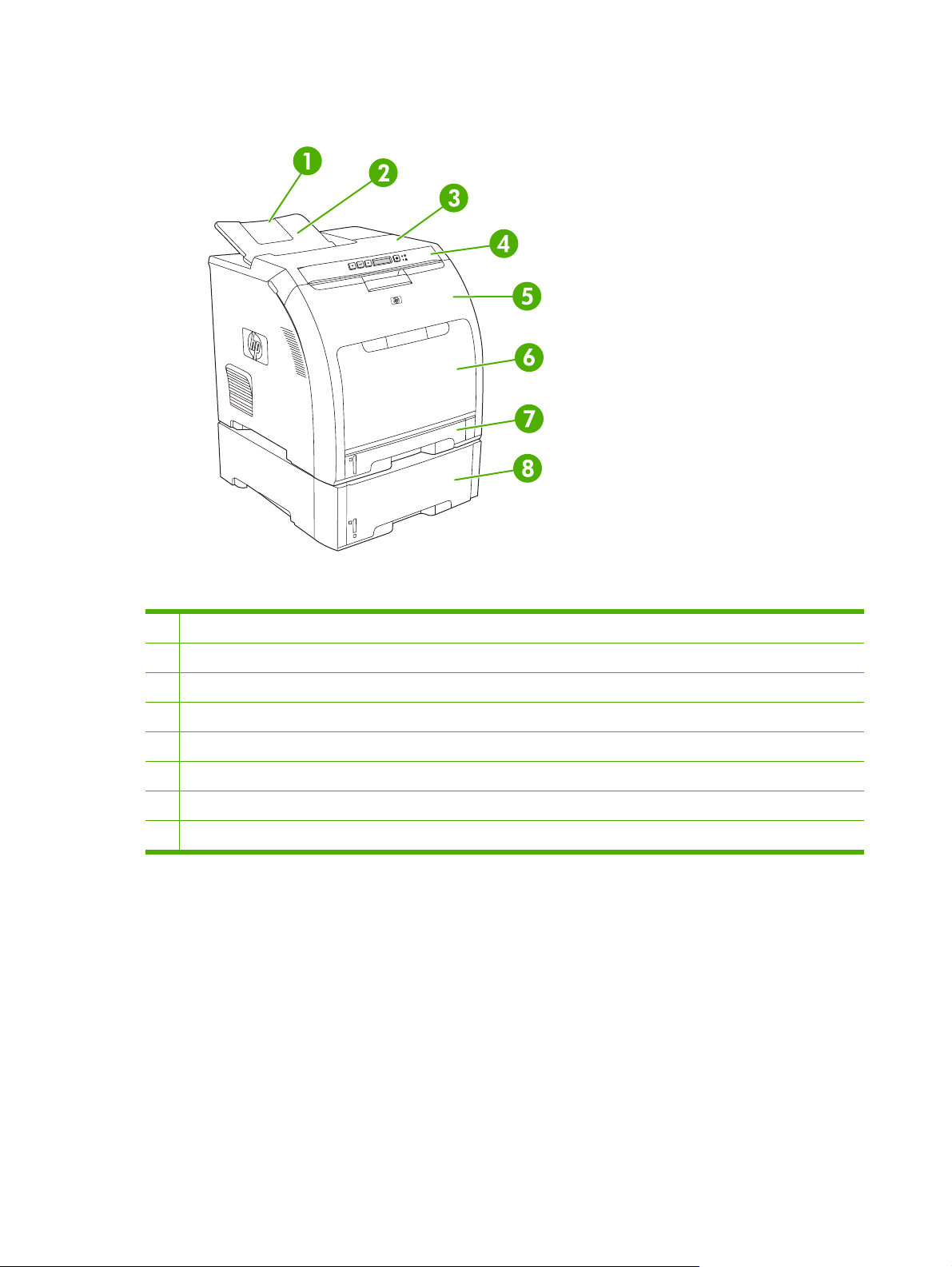
Walkaround
Figure 1-1 Front view (shown with optional 500-sheet input tray)
1 Output bin extender
2 Output bin
3 Top cover
4 Printer control panel
5 Front door
6 Tray 1 (holds 100 sheets of standard paper)
7 Tray 2 (holds 250 sheets of standard paper)
8 Tray 3 (optional; holds 500 sheets of standard paper)
4 Chapter 1 Product information ENWW
Page 23
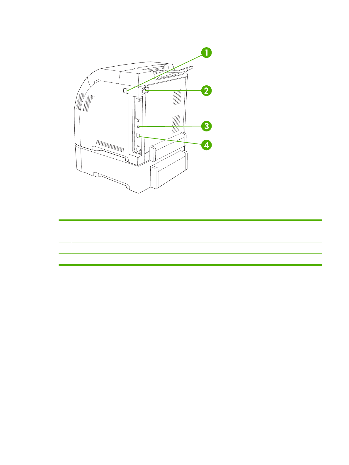
Figure 1-2 Back and side view
1 On/off (power) switch
2 Power connection
3 Hi-Speed USB 2.0 port
4 Network port (available on the HP Color LaserJet 2700n printer only)
ENWW Walkaround 5
Page 24
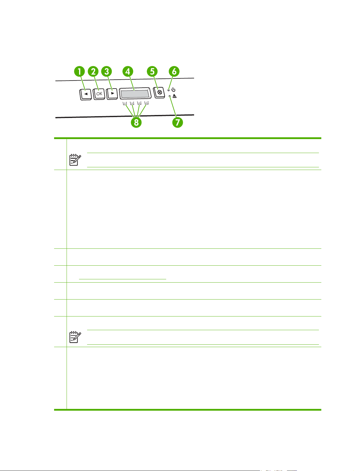
Understanding control-panel features
The printer has the following lights and buttons on the control panel:
1 Left arrow button (<): Press this button to navigate through the menus or to decrease a value that appears on the display.
NOTE Press the left and right arrow buttons simultaneously to print a demo page.
2 OK button: Press the OK button for the following actions:
Open the control-panel menus.
●
Select a menu item.
●
Clear some printer errors.
●
Continue printing after reloading a tray.
●
Acknowledge that a non-HP supply is in use.
●
Return the printer to the Ready state whenever the ready light is blinking.
●
3 Right arrow button (>): Press this button to navigate through the menus or to increase a value that appears on the
display.
4 Display: The display provides information about the printer. Use the menus on the display to establish printer settings.
See
Using the control-panel menus on page 7.
5 Cancel Job button (X): Press this button to cancel a print job whenever the attention light is blinking. You can also press
this button to exit the control-panel menus.
6 Ready light (green): The ready light is on when the printer is ready to print. It blinks when the printer is receiving print
data.
7 Attention light (amber): The attention light blinks when a print cartridge is empty.
NOTE The attention light does not blink if more than one print cartridge is empty.
8 Print-cartridge-status gauges: These gauges show the consumption level for each print cartridge (black, yellow, cyan,
and magenta).
If the consumption level is unknown, a ? symbol appears. This can occur in the following circumstances:
The print cartridge is missing or installed incorrectly.
●
The print cartridge is defective.
●
The print cartridge might not be an HP cartridge.
●
6 Chapter 1 Product information ENWW
Page 25

Using the control-panel menus
To use the menus
1. Press OK to open the menus.
2. Press < or > to navigate through the listings.
3. Press OK to select the appropriate option. An asterisk (*) appears next to the active selection.
4. Press X to exit the menu without saving any changes.
The sections that follow describe the options for each of the main menus:
Reports menu on page 8
●
System Setup menu on page 9
●
Network Config. menu (HP Color LaserJet 2700n printer only) on page 11
●
Service menu on page 12
●
ENWW Using the control-panel menus 7
Page 26

Reports menu
Use the Reports menu to print reports that provide information about the printer.
Menu item Description
Demo page Prints a color page that demonstrates print quality.
Menu structure Prints a map of the control-panel-menu layout. The active settings for each menu
are listed.
Config report Prints a list of all the printer settings. Includes network information when the printer
is connected to a network.
Supplies status Prints the status for each print cartridge, including the following information:
Estimated pages remaining
●
Part number
●
Number of pages printed
●
Network report Prints a list of all printer network settings (HP Color LaserJet 2700n printer only).
Usage page Lists PCL pages, PCL 6 pages, PS pages, pages that were jammed or mispicked in
the printer, monochrome (black and white) or color pages; and reports the page
count.
Color usage log Prints a report that shows the user name, application name, and color usage
information on a job-by-job basis.
PCL font list Prints a list of all the PCL fonts that are installed.
PS font list Prints a list of all the PostScript (PS) fonts that are installed.
PCL6 font list Prints a list of all the PCL6 fonts that are installed.
Service page Prints the service report.
8 Chapter 1 Product information ENWW
Page 27

System Setup menu
Use this menu to establish basic printer settings. The System Setup menu has several sub-menus.
Each is described in the following table.
Menu item Sub-menu item Sub-menu item Description
Language Select the language for the control-panel
display messages and the printer
reports.
Paper setup Def. paper size Letter
A4
Legal
Def. paper type A list of available media
types appears.
Tray 1 Paper size
Paper type
Tray 2 Paper size
Paper type
Tray 3 Paper size
Paper type
Paper out action Wait forever
Override
Cancel
Select the size for printing internal
reports or any print job that does not
specify a size.
Select the media type for printing internal
reports or any print job that does not
specify a type.
Select the default size and type for tray 1
from the list of available sizes and types.
Select the default size and type for tray 2
from the list of available sizes and types.
Select the default size and type for tray 3
from the list of available sizes and types.
Select how the printer should react when
a print job requires a size or type that is
not available or when a specified tray is
empty.
Select Wait forever to make the printer
wait until you load the correct media and
press OK. This is the default setting.
Select Override to print on a different
size or type after a specified delay.
Select Cancel to automatically cancel
the print job after a specified delay.
If you select either Override or Cancel,
the control panel prompts you to specify
the number of seconds to delay. Press
> to increase the time, up to
3600 seconds. Press < to decrease the
time.
Print quality Calibrate color After power on
Calibrate now
After power on: Select how soon the
printer should calibrate after you turn it
on. The default setting is 15 minutes.
Calibrate now: Makes the printer
perform a calibration immediately. If a job
is processing, the printer calibrates after
the job is complete. If an error message
is on the display, you must clear the error
first.
ENWW Using the control-panel menus 9
Page 28

Menu item Sub-menu item Sub-menu item Description
Color supply out Stop
Continue black
Replace supplies Override out
Stop at out
Cartridge low Low threshold (1-20) The percentage threshold determines
Restrict color Enable color
Disable color
Select Stop to halt printing until the
empty cartridge is replaced.
Select Continue black to allow future
color jobs to print in monochrome (black
and white) mode until the empty
cartridge is replaced.
Override out: If the printer determines
that a print cartridge is empty, you can
continue printing until you notice a
decrease in print quality.
Stop at out: If the printer determines that
a print cartridge is empty, you must
replace the cartridge before printing can
continue. This is the default setting.
when the printer begins reporting low
toner. The message is either reported on
the control-panel display or using the
toner LED, if it exists. The default setting
is 10%.
Select Enable color to allow the job to
print in either monochrome (black and
white) or color depending on the
specifications of the job.
Courier font Regular
Dark
Display contrast Medium
Darker
Darkest
Lightest
Lighter
Select Disable color to disable color
printing. All jobs will print in monochrome
(black and white).
Selects a version of the Courier font. The
default is Regular.
Select the level of contrast for the
display. The default setting is Medium.
10 Chapter 1 Product information ENWW
Page 29

Network Config. menu (HP Color LaserJet 2700n printer only)
Use this menu to establish network configuration settings.
Menu item Sub-menu item Description
TCP/IP config Automatic
Manual
Link Speed Automatic
10T Full
10T Half
100TX Full
100TX Half
Restore defaults Press OK to restore the network configuration
Select Automatic to automatically configure all the
TCP/IP settings.
Select Manual to manually configure the IP address,
subnet mask, and default gateway.
The printer should automatically detect the correct
link speed for the network. Use this menu to set the
link speed manually, if necessary.
After you set the link speed, the printer automatically
restarts.
settings to the default values.
ENWW Using the control-panel menus 11
Page 30

Service menu
Use this menu to restore default settings, clean the printer, and activate special modes that affect print
output.
Menu item Description
Restore defaults Sets all customized settings to the factory default values.
Cleaning mode Use this option to clean the printer if you see toner specks or other marks on the
printed output. The cleaning process removes dust and excess toner from the paper
path.
When you select this item, the printer prompts you to load plain paper in tray 1 and
then press OK to start the cleaning process. Wait until the process is complete.
Discard the page that prints.
USB speed Sets the USB speed to high or full. For the printer to actually operate at high speed,
it must have high speed enabled and be connected to an EHCI host controller which
is also operating at high speed. This menu item also does not reflect the current
operating speed of the printer.
Less paper curl If printed pages are consistently curled, use this option to set the printer to a mode
that reduces curl.
The default setting is Off.
Archive print If you are printing pages that will be stored for a long time, use this option to set the
printer to a mode that reduces toner smearing and dusting.
The default setting is Off.
12 Chapter 1 Product information ENWW
Page 31

Printer software
The printing-system software is included with the printer. See the getting started guide for installation
instructions.
The printing system includes software for end users and network administrators, and printer drivers for
access to the printer features and communication with the computer.
NOTE For a list of the network environments that the network-administrator software
components support, see
Network configuration (HP Color LaserJet 2700n only) on page 38.
For a list of printer drivers and updated HP printer software, go to
www.hp.com/go/
clj2700_software.
Supported operating systems and printer drivers
The printer uses the PCL 6 and PostScript 3 emulation PDL drivers.
NOTE For Windows 2000, Windows XP, and Windows Server 2003, the printer includes a
monochrome PCL 6 driver that can be installed for users who will be printing only black-and-white
print jobs.
Operating system
Windows 2000
Windows XP Home/Professional
Windows Server 2003
Mac OS X V10.2 and later
1
Not all printer features are available from all drivers or operating systems.
2
The printer includes both a monochrome and color PCL 6 driver for Windows 2000, Windows XP, and Windows Server 2003
users.
1
Network support PCL 6
2
PS 3 emulation
Additional drivers
The following drivers are not included on the CD, but are available from the following Web sites:
UNIX® model scripts:
●
Linux drivers
●
www.hp.com/go/linuxprinting
ENWW Printer software 13
www.hp.com/go/unixmodelscripts
Page 32

Opening the printer drivers
Operating System To change the settings for all
print jobs until the software
program is closed
Windows 2000, XP,
and Server 2003
Mac OS X V10.2 and
later
1. On the File menu in the
software program, click
Print.
2. Select the driver, and then
click Properties or
Preferences.
The steps can vary; this
procedure is most common.
1. On the File menu, click
Print.
2. Change the settings that
you want on the various
pop-up menus.
To change the default settings
for all print jobs
1. Click Start, click Settings,
and then click Printers or
Printers and Faxes.
2. Right-click the driver icon,
and then select Printing
Preferences.
1. On the File menu, click
Print.
2. Change the settings that
you want on the various
pop-up menus.
3. On the Presets pop-up
menu, click Save as and
type a name for the preset.
These settings are saved in the
Presets menu. To use the new
settings, you must select the
saved preset option every time
you open a program and print.
To change the product
configuration settings
1. Click Start, click Settings,
and then click Printers or
Printers and Faxes.
2. Right-click the driver icon,
and then select
Properties.
3. Click the Device Settings
tab.
1. In the Finder, on the Go
menu, click Applications.
2. Open Utilities, and then
open Print Center (Mac OS
X V10.2 and V10.3) or
Printer Setup Utility (Mac
OS X V10.4).
3. Click on the print queue.
4. On the Printers menu,
click Show Info.
5. Click the Installable
Options menu.
NOTE Configuration
settings might not be
available in Classic
mode.
14 Chapter 1 Product information ENWW
Page 33

Software for Windows
The HP ToolboxFX
The HP ToolboxFX is a software program that you can use for the following tasks:
Checking the printer status
●
Checking the supplies status and ordering supplies online
●
Setting up alerts
●
Setting up e-mail notification for certain printer and supplies events
●
Viewing and changing printer settings
●
Viewing printer documentation
●
Gaining access to troubleshooting and maintenance tools
●
You can view the HP ToolboxFX when the printer is directly connected to your computer or when it is
connected to a network. Perform a complete software installation in order to use the HP ToolboxFX.
Software for Macintosh
The HP installer provides PostScript Printer Description (PPD) files, Printer Dialog Extensions (PDEs),
and the Macintosh Configure Device software for use with Macintosh computers.
If both the printer and the Macintosh computer are connected to a network, use the embedded Web
server to configure the printer. For more information, see
on page 59.
Using the embedded Web server
PostScript Printer Description (PPD) files
The PPDs, in combination with the Apple PostScript printer drivers, provide access to printer features.
An installation program for the PPDs and other software is provided on the CD that comes with the
printer. Use the Apple PostScript printer driver that comes with the computer.
Macintosh Configure Device
The Macintosh Configure Device software provides access to features that are not available in the printer
driver. Use the illustrated screens to select printer features and complete the following tasks:
Name the printer.
●
Assign the printer to a zone on the network.
●
Assign an Internet protocol (IP) address to the printer.
●
Configure the printer for network printing.
●
Macintosh Configure Device is available for USB and network connections.
For more information about using Macintosh Configure Device, see
Device on page 69.
Using Macintosh Configure
ENWW Printer software 15
Page 34

Software for networks
HP Web Jetadmin
HP Web Jetadmin is a browser-based management tool for network-connected printers within your
intranet. It should be installed only on the network administrator’s computer.
To download a current version of HP Web Jetadmin and for the latest list of supported host systems,
www.hp.com/go/webjetadmin.
visit
When installed on a host server, any client can gain access to HP Web Jetadmin by using a supported
Web browser (such as Microsoft® Internet Explorer 6.x or Netscape Navigator 7.x or later) and
navigating to the HP Web Jetadmin host.
UNIX
For HP-UX and Solaris networks, go to www.hp.com/support/net_printing to download the network
printer installer for UNIX.
Linux
For information, go to www.hp.com/go/linuxprinting.
Embedded Web server
The HP Color LaserJet 2700n printer is equipped with an embedded Web server, which provices access
to information about printer and network activities. This information appears in a Web browser, such as
Microsoft Internet Explorer or Netscape Navigator.
The embedded Web server resides on the printer. It is not loaded on a network server. The embedded
Web server is available only when the printer is connected to a network. No special software is installed
or configured, but you must have a supported Web browser on your computer.
For a complete explanation of the features and functionality of the embedded Web server, see
the embedded Web server on page 59.
Using
16 Chapter 1 Product information ENWW
Page 35

Print-media specifications
For optimum results, use conventional 75 g/m2 to 90 g/m2 (20 to 24 lb) photocopy paper. Verify that the
paper is of good quality and is free of cuts, nicks, tears, spots, loose particles, dust, wrinkles, curls, or
bent edges.
Tray 1 and tray 2
Media type Dimensions
1
Paper (including postcards) Minimum: 76 x 127 mm
(3 x 5 inches)
Maximum: 216 x 356 mm
Weight Capacity
60 to 163 g/m2 (16 to 43 lb)
Up to 176 g/m
2
(47 lb) for
Tray 1: up to 100 sheets
Tray 2: up to 250 sheets
postcards
2
(8.5 x 14 inches)
HP Color Laser Photo Paper,
gloss and HP Color Laser
Photo Paper, matte
HP Cover Paper
3
3
Same as for paper
Same as for paper
75 to 220 g/m2 (20 to 58 lb)
200 g/m2 (53 lb)
Tray 1: up to 60 sheets
Tray 2: up to 100 sheets
Tray 1: up to 60 sheets
Tray 2: up to 100 sheets
Transparencies and opaque
film
Same as for paper Thickness: 0.12 to 0.13 mm
(4.7 to 5.1 mils)
Tray 1: up to 60 sheets
Tray 2: up to 50 sheets
4
Labels
Same as for paper Thickness: up to 0.23 mm
Tray 1: up to 60 sheets
(9 mils)
Tray 2: up to 100 sheets
Envelopes Same as for paper
Up to 90 g/m2 (24 lb)
Tray 1: up to 10 envelopes
Tray 2: up to 10 envelopes
1
The printer supports a wide range of standard and custom sizes of print media. Check the printer driver for supported sizes.
2
Capacity can vary depending on media weight and thickness, and environmental conditions.
3
Hewlett-Packard does not guarantee results when printing on other types of heavy paper.
4
Smoothness: 100 to 250 (Sheffield)
ENWW Print-media specifications 17
Page 36

Optional tray 3
Media type Size Weight Capacity
Paper Letter
60 to 120 g/m2 (16 to 32 lb)
Up to 500 sheets
Legal
Executive
A4
A5
B5-JIS
8.5 x 13
HP Color Laser Photo Paper,
gloss and HP Color Laser
Photo Paper, matte
2
Cardstock Same as for paper
Letterhead Same as for paper
1
Capacity can vary depending on media weight and thickness, and environmental conditions.
2
Hewlett-Packard does not guarantee results when printing on other types of heavy paper.
Same as for paper
106 to 120 g/m2 (28 to 32 lb)
up to 120 g/m2 (32 lb)
60 to 120 g/m2 (16 to 32 lb)
Up to 200 sheets
Up to 200 sheets
Up to 500 sheets
1
18 Chapter 1 Product information ENWW
Page 37

Selecting print media
You can use many types of paper and other print media with this printer.
Before purchasing any paper or specialized forms in quantity, verify that your paper supplier has
obtained and understands the print-media requirements that are specified in the HP LaserJet Printer
Family Print Media Specification Guide.
Accessories and supplies on page 239 to order the HP LaserJet Printer Family Print Media
See
Specification Guide. To download a copy of the guide, go to
Select Manuals.
It is possible that paper could meet all of the guidelines in this chapter or the HP LaserJet Printer Family
Print Media Specification Guide and still not print satisfactorily. This can result from abnormal
characteristics of the printing environment or other variables over which HP has no control (for example,
extremes in temperature and humidity).
Hewlett-Packard Company recommends testing any paper before buying it in large quantities.
CAUTION Using paper that does not conform to the specifications listed here or in the print
media guide can cause problems that require service. This service is not covered by the HewlettPackard warranty or service agreements.
Paper to avoid
www.hp.com/support/ljpaperguide.
The printer can handle many types of paper. Using paper that does not meet specifications will cause
lower print quality and increase the chance of jams.
Do not use paper that is too rough.
●
Do not use paper, other than standard prepunched paper, that contains cutouts or perforations.
●
Do not use multipart forms.
●
Do not use paper that has already been printed on, or that has been fed through a photocopier.
●
Do not use paper that contains a watermark if you are printing solid patterns.
●
Paper that can damage the printer
In rare circumstances, paper can damage the printer. The following paper must be avoided to prevent
possible damage to the printer:
Do not use paper with staples attached.
●
Do not use transparencies that are designed for Inkjet printers or other low temperature printers,
●
or for monochrome printing. Use only transparencies that are specified for use with HP Color
LaserJet printers.
Do not use photo paper that is intended for Inkjet printers.
●
Do not use paper that is embossed or coated, or any media that produces hazardous emissions,
●
or that melts, offsets, or discolors when exposed to 190°C (374°F) for 0.1 second. Also, do not use
letterhead paper that is made with dyes or inks that cannot withstand that temperature.
ENWW Selecting print media 19
Page 38

Printing and storage environment
Ideally, the printing and media-storage environment should be at or near room temperature, and not too
dry or too humid. Remember that paper is hygroscopic; it absorbs and loses moisture rapidly.
Heat causes the moisture in paper to evaporate, while cold causes it to condense on the sheets. Heating
systems and air conditioners remove most of the humidity from a room. As paper is opened and used,
it loses moisture, causing streaks and smudging. Humid weather or water coolers can cause the humidity
to increase in a room. As paper is opened and used it absorbs any excess moisture, causing light print
and dropouts. Also, as paper loses and gains moisture it can distort. This issue can cause jams.
As a result, paper storage and handling are as important as the paper-making process itself. Paper
storage environmental conditions directly affect the feed operation and print quality.
Evaluate purchasing more paper than can be easily used in a short time, about three months. Paper
stored for long periods can experience heat and moisture extremes, which can cause damage. Planning
is important to prevent damage to a large supply of paper.
Unopened paper in sealed reams can remain stable for several months before use. Opened packages
of paper have more potential for environmental damage, especially if they are not wrapped with a
moisture-proof barrier.
The media-storage environment should be properly maintained to ensure optimum printer performance.
The recommended condition is 20° to 24°C (68° to 75°F), with a relative humidity of 45% to 55%. The
following guidelines should be helpful when evaluating the paper storage environment:
Print media should be stored at or near room temperature.
●
The air should not be too dry or too humid to moderate the hygroscopic properties of paper.
●
The best way to store an opened ream of paper is to rewrap it tightly in its moisture-proof wrapping.
●
If the printer environment is subject to extremes, unwrap only the amount of paper to be used during
the day's operation to prevent unwanted moisture changes.
Avoid storing paper and print media near heating and air conditioning vents or near windows and
●
doors that are frequently open.
20 Chapter 1 Product information ENWW
Page 39

Printing on special media
Transparencies
Handle transparencies by the edges. Oils from your fingers can cause print-quality problems.
●
Use only overhead transparencies recommended for use in this printer. Hewlett-Packard
●
recommends using HP Color LaserJet Transparencies with this printer. HP products are designed
to work together for optimum printing results.
In either the software program or the printer driver, select Transparency as the media type, or
●
print from a tray that is configured for transparencies.
CAUTION Transparencies that are not designed for laser printing might melt in the printer,
causing damage to the printer.
Glossy paper
In either the software program or the driver, select GLOSSY as the media type, or print from a tray
●
that is configured for glossy paper.
Because this affects all print jobs, it is important to return the printer to its original settings once the
●
job has printed. See
Configuring trays on page 28 for more information.
Colored paper
Colored paper should be of the same high quality as white xerographic paper.
●
Pigments used must be able to withstand the printer’s fusing temperature of 190°C (374°F) for 0.1
●
second without deterioration.
Do not use paper with a colored coating that was added after the paper was produced.
●
The printer creates colors by printing patterns of dots, overlaying and varying their spacing to
●
produce various colors. Varying the shade or color of the paper will affect the shades of the printed
colors.
Envelopes
Adhere to the following guidelines to help ensure proper printing on envelopes and to help prevent printer
jams:
In either the software program or the printer driver, select Envelope as the media type, or configure
●
tray 1 for envelopes. See
The weight rating of envelopes should not exceed 90 g/m
●
Envelopes should be flat.
●
Do not use envelopes with windows or clasps.
●
Configuring trays on page 28.
2
(24 lb bond).
Envelopes must not be wrinkled, nicked, or otherwise damaged.
●
Envelopes with peel-off adhesive strips must use adhesives that can withstand the heat and
●
pressures of the printer’s fusing process.
ENWW Printing on special media 21
Page 40

If your software does not automatically format an envelope, specify Landscape for page orientation in
the software program. Use the guidelines in the table that follows to set margins for return and destination
addresses on Commercial #10 or DL envelopes.
Address type Left margin Top margin
Return 15 mm (0.6 inch) 15 mm (0.6 inch)
Destination 102 mm (4.0 inch) 51 mm (2.0 inch)
Labels
In either the software program or the printer driver, select Labels as the media type, or configure
●
tray 1 or tray 2 for labels. See
Verify that the labels’ adhesive material can tolerate temperatures of 190°C (374°F) for 0.1 second.
●
Verify that there is no exposed adhesive material between the labels. Exposed areas can cause
●
labels to peel off during printing, which can cause paper jams. Exposed adhesive can also cause
damage to printer components.
Do not re-feed a sheet of labels.
●
Verify that labels lie flat.
●
Configuring trays on page 28.
Do not use labels that are wrinkled, bubbled, or otherwise damaged.
●
Heavy paper
For information about which heavy paper is supported in each tray, see
●
specifications on page 17
In either the software program or the printer driver, select Heavy or Cardstock as the media type,
●
or print from a tray that is configured for heavy paper. Because this setting affects all print jobs, it
is important to return the printer back to its original settings after the job has been printed. See
Configuring trays on page 28.
CAUTION In general, do not use paper that is heavier than the media specification
recommended for this printer. Doing so can cause misfeeds, jams, reduced print quality, and
excessive mechanical wear.
Print-media
Preprinted forms and letterhead
Forms and letterhead must be printed with heat-resistant inks that will not melt, vaporize, or release
●
hazardous emissions when subjected to the printer’s fusing temperature of approximately 190°C
(374°F) for 0.1 second.
Inks must be nonflammable and should not adversely affect any printer rollers.
●
Forms and letterhead should be sealed in a moisture-proof wrapping to prevent changes during
●
storage.
Before loading preprinted paper, verify that the ink on the paper is dry. During the fusing process,
●
wet ink can come off of preprinted paper.
22 Chapter 1 Product information ENWW
Page 41

NOTE For information about how to load letterhead and preprinted forms, see Loading special
media on page 36.
Recycled paper
This printer supports the use of recycled paper. Recycled paper must meet the same specifications as
standard paper. See the HP LaserJet Printer Family Print Media Specification Guide. Hewlett-Packard
recommends that recycled paper contain no more than 5% ground wood.
HP LaserJet media
Hewlett-Packard offers many types of media that are made specifically for use in HP LaserJet printers.
HP products are designed to work together for optimum printing results.
For more information about HP LaserJet media, go to
www.hp.com.
ENWW Printing on special media 23
Page 42

24 Chapter 1 Product information ENWW
Page 43

2 Installation and configuration
What is in the box
●
Site requirements
●
Configuring trays
●
USB configuration
●
Network configuration (HP Color LaserJet 2700n only)
●
Printer memory
●
ENWW 25
Page 44

What is in the box
The following items come in the box with the printer.
Figure 2-1 What is in the shipping box
1. Printer
2. Getting started guide
3. Power cord
4. Output bin
5. CD that contains the printer software and the electronic user guide.
26 Chapter 2 Installation and configuration ENWW
Page 45

Site requirements
Select a sturdy, well-ventilated, dust-free area that is away from direct sunlight to position the printer.
Allow enough space around the printer to open the doors and trays.
Physical specifications
Product Height Depth Width Weight
400 mm
Base model
Base model plus optional tray 3 540 mm
1
The printer weight does not include print cartridges.
(15.7 inches)
(21.3 inches)
450 mm
(17.7 inches)
450 mm
(17.7 inches)
400 mm
(15.7 inches)
400 mm
(15.7 inches)
20.3 kg (44.8 lb)
25.4 kg (56.0 lb)
1
ENWW Site requirements 27
Page 46

Configuring trays
You can configure the printer trays by type and size. Load different media in the printer trays and then
request media by type or size in the software program.
The following instructions are for configuring the trays at the printer control panel. You can also configure
the trays from your computer through the embedded Web server (see
server on page 59) or through HP ToolboxFX (see Using the HP ToolboxFX on page 62).
Configuring size
1. Press OK.
2. Press > to highlight System Setup, and then press OK.
3. Press > to highlight Paper Setup, and then press OK.
4. Press > to highlight Tray 1 or Tray 2, and then press OK.
5. Press > to highlight Paper size, and then press OK.
6. Press > to highlight the appropriate size, and then press OK.
Configuring type
1. Press OK.
Using the embedded Web
2. Press > to highlight System Setup, and then press OK.
3. Press > to highlight Paper Setup, and then press OK.
4. Press > to highlight Tray 1 or Tray 2, and then press OK.
5. Press > to highlight Paper type, and then press OK.
6. Press > to highlight the appropriate type, and then press OK.
Configuring trays for custom paper
Some software programs and printer drivers allow you to specify custom media-size dimensions. Be
sure to set the correct media size in both the page setup and print dialog boxes. If your software does
not allow this, specify the custom media-size dimensions at the control panel. See
menu on page 9 for more information.
Use the Any size size setting when the selected media does not exactly match the size of the paper
specified in the document you are printing. If no source tray is specified, the printer looks first for paper
that exactly matches the document, and then it looks for and prints from a tray set to Any size or Any
type.
System Setup
Printing from tray 1 (100-sheet multipurpose tray)
Tray 1 holds up to 100 sheets of media. It provides a convenient way to print envelopes, transparencies,
custom-size paper, or other types of paper without having to unload the other trays.
Loading tray 1
See Print-media specifications on page 17 for a list of media types and sizes that tray 1 supports.
28 Chapter 2 Installation and configuration ENWW
Page 47

CAUTION Avoid adding print media to tray 1 while the printer is printing, or jams can occur.
1. Open tray 1.
2. Slide the output bin extension out from the bin.
3. Slide out the tray extender and, if necessary, open the additional tray extender.
ENWW Configuring trays 29
Page 48

4. Slide the width guides to the size of the print media.
5. Place print media into the tray with the side to be printed down, and the top, short edge in first.
Load an envelope with the side to be printed down, the stamp area farthest from the printer, and
the short edge toward the printer.
NOTE See Loading special media on page 36 for complete information about how to
orient the media and configure the printer.
Printing from tray 2 or optional tray 3
Tray 2 holds up to 250 sheets of standard paper, and optional tray 3 holds up to 500 sheets of standard
paper. Tray 2 and optional tray 3 adjust for many sizes. Optional tray 3 is installed underneath tray 2.
When optional tray 3 is installed, the printer detects it and lists tray 3 as a choice in the control panel
Paper setup menu.
CAUTION The paper path for optional tray 3 passes through tray 2. If either tray 2 or tray 3 is
partially pulled out or removed, media from tray 3 cannot feed into the printer.
30 Chapter 2 Installation and configuration ENWW
Page 49

Loading tray 2
CAUTION To avoid jams, never open or remove a tray during printing.
1. Pull tray 2 out of the printer and remove any media.
2. Slide the output bin extension out from the bin.
3. Adjust the length guide until the arrow points to the size that you are loading.
ENWW Configuring trays 31
Page 50

4. Adjust the side width guides until the arrow on the right width guide points to the size that you are
loading.
5. Load the media into the tray.
NOTE If you are printing on special media such as labels, letterhead, or envelopes, see
Loading special media on page 36 for complete information about how to orient the media
and configure the printer.
6. Make sure that the stack of media is flat and that the media is below the height tabs.
32 Chapter 2 Installation and configuration ENWW
Page 51

7. Slide the tray back into the printer.
Loading optional tray 3
1. Pull the tray out of the printer and remove any media.
2. Raise the output bin extension.
ENWW Configuring trays 33
Page 52

3. Adjust the length guide until the arrow points to the size that you are loading.
4. Adjust the side width guides until the arrow on the right width guide points to the size that you are
loading.
5. Load the media into the tray. If you are printing on special media such as labels or letterhead,
Loading special media on page 36 for complete information about how to orient the media
see
and configure the printer.
34 Chapter 2 Installation and configuration ENWW
Page 53

6. Make sure that the stack of media is flat in the tray at all four corners, and keep it below the height
tabs.
7. Slide the tray back into the printer.
ENWW Configuring trays 35
Page 54

Loading special media
The following table provides guidelines for loading special media and configuring the printer driver. Use
the correct media-type setting in the printer driver to obtain the best print quality. For some types of
media, the printer reduces the print speed.
NOTE In the Windows printer driver, adjust the media type on the Paper tab in the Type is
drop-down list.
In the Macintosh printer driver, adjust the media type on the Printer features pop-up menu in
the Media type drop-down list.
Media type Printer-driver setting Tray 1 media orientation Tray 2 or tray 3 media
orientation
Normal Plain or unspecified Side to be printed facing down Side to be printed facing up
Envelopes
Labels Labels Side to be printed facing down Side to be printed facing up
Transparencies Transparencies Side to be printed facing down Side to be printed facing up
Glossy Glossy Side to be printed facing down Side to be printed facing up
1
Envelope Side to be printed facing
down, stamp area farthest
from the printer, short edge
toward the printer
Use only tray 1 for printing
envelopes
Letterhead Letterhead Side to be printed facing
down, bottom edge toward the
printer
Light Light Side to be printed facing down Side to be printed facing up
Intermediate Intermediate Side to be printed facing down Side to be printed facing up
Heavy Heavy Side to be printed facing down Side to be printed facing up
Extra heavy Extra heavy Side to be printed facing down Side to be printed facing up
Cardstock Cardstock Side to be printed facing down Side to be printed facing up
Rough Rough Side to be printed facing down Side to be printed facing up
1
Tray 2 and optional tray 3 do not support envelopes.
Side to be printed facing up,
top edge at the front of the tray
For more information about print media, go to www.hp.com/support/ljpaperguide
36 Chapter 2 Installation and configuration ENWW
Page 55

USB configuration
All printer models support USB connections. The USB port is on the right side of the printer.
Connecting the USB cable
Plug the USB cable into the printer. Plug the other end of the USB cable into the computer.
Figure 2-2 USB port connection
1 USB port
2 USB cable
ENWW USB configuration 37
Page 56

Network configuration (HP Color LaserJet 2700n only)
You might need to configure certain network parameters on the printer. You can configure these
parameters from the printer control panel, the embedded Web server, or, for Windows operating
systems, from the HP ToolboxFX software.
Set up the printer and use it on the network
Hewlett-Packard recommends that you use the HP software installer on the CD-ROMs that came with
the printer to set up printer drivers for networks.
To set up a network port-connected configuration (direct mode or peer-to-peer printing)
In this configuration, the printer is connected directly to the network, and all computers on the network
print directly to the printer.
1. Connect the printer directly to the network by inserting a network cable into the printer network port.
2. At the printer, use the control panel to print a Configuration page. See
3. Insert the printer CD-ROM into your computer. If the software installer does not start, navigate to
the HPSETUP.EXE file on the CD-ROM and double-click the file.
4. Click Install.
5. On the Welcome screen, click Next.
6. On the Installer updates screen, click Yes to search for installer updates on the Web.
7. For Windows 2000/XP, on the Installation Options screen, choose the installation option. Hewlett-
Packard recommends a typical installation, if your system supports it.
8. On the License Agreement screen, read the license agreement, indicate that you accept the
terms, and then click Next.
9. For Windows 2000/XP, on the HP Extended Capabilities screen, choose whether you want
extended capabilities, and then click Next.
10. On the Destination Folder screen, choose the destination folder, and then click Next.
11. On the Ready to Install screen, click Next to begin installation.
NOTE If you want to change your settings, instead of clicking Next, click Back to return
to previous screens, and then change the settings.
Reports menu on page 8.
12. On the Connection Type screen, select Through the network, and then click Next.
13. On the Identify Printer screen, identify the printer either by searching for it or by specifying a
hardware or IP address, which is listed on the Configuration page you printed earlier. In most cases
an IP address is assigned, but you can change it by clicking Specify the printer by Address on
the Identify Printer screen. Click Next.
14. Allow the installation process to complete.
38 Chapter 2 Installation and configuration ENWW
Page 57

Using the embedded Web server or the HP ToolboxFX
You can use the embedded Web server (EWS) or the HP ToolboxFX to view or change your IP
configuration settings. To access the embedded Web server, type the IP address for the printer in the
address line of the browser.
For complete information about using the embedded Web server and the HP ToolboxFX software,
including instructions about how to open these tools, see
on page 59 and Using the HP ToolboxFX on page 62.
From the Networking tab (EWS) or the Network Settings tab (the HP ToolboxFX), you can change
the following configurations:
Host Name
●
Manual IP Address
●
Manual Subnet Mask
●
Manual Default Gateway
●
NOTE Changing the network configuration might require you to change the browser URL before
you can communicate with the printer again. The printer will be unavailable for a few seconds
while the network resets.
Using the embedded Web server
Setting a system password
Use the HP ToolboxFX or the embedded Web server to set a system password.
1. In the embedded Web server, click the Settings tab.
In the HP ToolboxFX, click the Device Settings tab.
NOTE If a password has been set for the printer previously, you will be prompted to type
the password. Type the password, and then click Apply.
2. Click Password.
3. In the Password box, type the password that you want to set, and then in the Confirm
password box, type the same password again to confirm your choice.
4. Click Apply to save the password.
Using the printer control panel
IP configuration
You can configure the IP address manually or automatically.
Manual configuration
1. On the control panel menu, press OK.
2. Use the < or the > button to select Network Config., and then press OK.
3. Use the < or the > button to select TCP/IP config, and then press OK.
ENWW Network configuration (HP Color LaserJet 2700n only) 39
Page 58

4. Use the < or the > button to select Manual, and then press OK.
5. Press the > button to increase the value for the first section of the IP address. Press the < button
to decrease the value. When the value is correct, press OK to accept the value and move the cursor
to the next field.
6. If the address is correct, use the < or the > button to select Yes, and then press OK. Repeat step
5 for the subnet mask and default gateway settings.
-or-
If the IP address is incorrect, use the < or the > button to select No, and then press OK. Repeat
step 5 to establish the correct IP address, and then repeat step 5 for the subnet mask and default
gateway settings.
Automatic configuration
1. On the control panel menu, press OK.
2. Use the < or the > button to select Network Config., and then press OK.
3. Use the < or the > button to select TCP/IP config, and then press OK.
4. Use the < or the > button to select Automatic, and then press OK.
It might take several minutes before the automatic IP address is ready for use.
NOTE If you want to disable or enable specific automatic IP modes (such as BOOTP, DHCP,
or AutoIP), these settings can be changed by using the embedded Web server or the
HP ToolboxFX only.
Link speed and link duplex settings
NOTE Incorrect changes to the link speed and link duplex settings might prevent the printer
from communicating with other network devices. For most situations, use the Automatic mode.
Making changes causes the printer to restart. Make changes only while the printer is idle.
1. On the control panel menu, press OK.
2. Use the < or the > button to select Network Config., and then press OK.
3. Use the < or the > button to select Link Speed, and then press OK.
4. Use the < or the > button to select one of the following settings.
10T Full
●
10T Half
●
100TX Full
●
100TX Half
●
NOTE The printer setting must be the same as the setting for the network device to which
you are connecting (a network hub, switch, gateway, router, or computer).
5. Press OK. The printer restarts.
40 Chapter 2 Installation and configuration ENWW
Page 59

Supported network protocols
The printer supports the TCP/IP network protocol, the most widely used and accepted networking
protocol. Many networking services utilize this protocol. For more information, see
on page 42. The following table lists the supported networking services and protocols.
Table 2-1 Printing
Service name Description
port9100 (Direct Mode) Printing service
Line printer daemon (LPD) Printing service
Table 2-2 Network device discovery
Service name Description
TCP/IP
SLP (Service Location Protocol) Device-discovery protocol, used to help find and configure
Bonjour Device-discovery protocol, used to help find and configure
network devices. Used primarily by Microsoft-based programs.
network devices. Used primarily by Apple Macintosh-based
programs.
Table 2-3 Messaging and management
Service name Description
HTTP (Hyper Text Transfer Protocol) Allows Web browsers to communicate with embedded Web
server.
EWS (embedded Web server) Allows a user to manage the device through a Web browser.
SNMP (Simple Network Management Protocol) Used by network applications for device management. SNMP
v1 and standard MIB-II (Management Information Base)
objects are supported.
Table 2-4 IP addressing
Service name Description
DHCP (Dynamic Host Configuration Protocol) For automatic IP address assignment. The DHCP server
provides the printer with an IP address. Generally, no user
intervention is required for the printer to obtain an IP address
from a DHCP server.
BOOTP (Bootstrap Protocol) For automatic IP address assignment. The BOOTP server
provides the printer with an IP address. Requires the
administrator to input a device's MAC hardware address on the
BOOTP server for the printer to obtain an IP address from that
server.
Auto IP For automatic IP address assignment. If neither a DHCP
server nor a BOOTP server is present, the printer uses this
service to generate a unique IP address.
ENWW Network configuration (HP Color LaserJet 2700n only) 41
Page 60

TCP/IP
Similar to a common language that people use to communicate with each other, TCP/IP (Transmission
Control Protocol/Internet Protocol) is a suite of protocols designed to define the way computers and
other devices communicate with each other over a network.
Internet Protocol (IP)
When information is sent across the network, the data is broken down into small packets. Each packet
is sent independently. Each packet is encoded with IP information, such as the IP address of the sender
and receiver. IP packets can be routed over routers and gateways: devices that connect a network with
other networks.
IP communications require no connection. When IP packets are sent, they might not arrive at their
destination in the correct sequence. However, higher-level protocols and programs place the packets
in the correct sequence, so IP communications are efficient.
Each node or device that communicates on the network requires an IP address.
Transmission Control Protocol (TCP)
TCP breaks the data into packets and recombines them on the receiving end by providing a connectionoriented, reliable, and guaranteed delivery service to another node on the network. When data packets
are received at their destination, TCP calculates a checksum for each packet to verify that the data is
not corrupt. If the data in the packet has been corrupted during transmission, TCP discards the packet
and requests that the packet be resent.
IP address
Every host (workstation or node) on an IP network requires a unique IP address for each network
interface. This address is a software address that is used to identify both the network and specific hosts
that are located on that network. It is possible for a host to query a server for a dynamic IP address each
time the device boots up (for example, using DHCP and BOOTP).
An IP address contains four bytes of information, divided into sections that each contain one byte. The
IP address has the following format:
xxx.xxx.xxx.xxx
NOTE When assigning IP addresses, always consult the IP address administrator. Setting the
wrong address can disable other equipment operating on the network or interfere with
communications.
Configuring IP parameters
TCP/IP configuration parameters can be configured manually, or they can be automatically downloaded
by using DHCP or BOOTP each time the printer is turned on.
When turned on, a new printer that is unable to retrieve a valid IP address from the network automatically
assigns itself a default IP address. The default IP address depends on the type of network to which the
printer is connected. On a small private network, a technique called link-local addressing is used to
assign a unique IP address in the range of 169.254.1.0 to 169.254.254.255, which should be valid. On
a large or enterprise network, a temporary address of 192.0.0.192 is assigned until the printer is
configured for your network. The IP address for the printer is listed on the printer Configuration page.
42 Chapter 2 Installation and configuration ENWW
Page 61

Dynamic Host Configuration Protocol (DHCP)
DHCP allows a group of devices to use a set of IP addresses that are maintained by a DHCP server.
The device or host sends a request to the server, and if an IP address is available, the server assigns
it to that device.
BOOTP
BOOTP is a bootstrap protocol used to download configuration parameters and host information from
a network server. In order for devices to start and load configuration information into RAM, they must
communicate with the server as a client through the bootstrap protocol BOOTP.
The client broadcasts a boot request packet that contains the hardware address of the device (the printer
hardware address). The server answers with a boot reply packet that contains the information that the
device needs for configuration.
Subnets
When an IP network address for a particular network class is assigned to an organization, no provision
is made for more than one network being present at that location. Local network administrators use
subnets to partition a network into several different subnetworks. Splitting a network into subnets can
result in better performance and improved use of limited network address space.
Subnet mask
The subnet mask is a mechanism used to divide a single IP network into several different subnetworks.
For a given network class, a portion of an IP address that would normally be used to identify a node is
used, instead, to identify a subnetwork. A subnet mask is applied to each IP address to specify the
portion used for subnetworks, and the portion used to identify the node.
Gateways
Gateways (routers) are used to connect networks together. Gateways are devices that act as translators
between systems that do not use the same communication protocols, data formatting, structures,
languages, or architectures. Gateways repackage the data packets and change the syntax to match
that of the destination system. When networks are divided into subnets, gateways are required to
connect one subnet to another.
Default gateway
The default gateway is the IP address of the gateway or router that moves packets between networks.
If multiple gateways or routers exist, then the default gateway is typically the address of the first, or
nearest, gateway or router. If no gateways or routers exist, then the default gateway will typically assume
the IP address of the network node (such as the workstation or printer).
ENWW Network configuration (HP Color LaserJet 2700n only) 43
Page 62

Printer memory
The printer has one dual inline memory module (DIMM) slot. Use the DIMM slot to upgrade the printer
with the following items:
More printer memory (DIMMs are available in 64, 128, and 256 MB).
●
Other DIMM-based printer languages and printer options
●
NOTE Single in-line memory modules (SIMMs) that are used on previous HP LaserJet printers
are not compatible with these printers.
You might want to add more memory to the printer if you often print complex graphics or PostScript
documents, if you use many downloaded fonts, or if a Jetdirect EIO print server will be installed for
network printing capabilities. Additional memory also allows the printer to print multiple collated copies
at the maximum speed.
Before ordering additional memory, see how much memory is currently installed by printing a
configuration page. See
Installing memory DIMMs
You can install more memory for the printer, and you can also install a font DIMM to allow the printer to
print characters for languages such as Chinese or the Cyrillic alphabet.
Using printer information pages on page 58.
CAUTION Static electricity can damage DIMMs. When handling DIMMs, either wear an
antistatic wrist strap, or frequently touch the surface of the DIMM antistatic package and then
touch bare metal on the printer.
To install memory and font DIMMs
1. Turn the printer off, and then disconnect all power and interface cables.
44 Chapter 2 Installation and configuration ENWW
Page 63

2. On the right side of the printer, gently pull the black tabs together, and then pull the formatter
assembly from the printer.
3. Place the formatter board on a clean, flat, grounded surface.
To replace a DIMM that is currently installed, spread the latches apart on each side of the DIMM
slot, lift the DIMM up at an angle, and pull it out.
4. Remove the new DIMM from the antistatic package, and then locate the alignment notch on the
bottom edge of the DIMM.
ENWW Printer memory 45
Page 64

5. Holding the DIMM by the edges, align the notch on the DIMM with the bar in the DIMM slot at an
angle and firmly press the DIMM into the slot until it is fully seated. When installed correctly, the
metal contacts are not visible.
6. Push down on the DIMM until both latches engage the DIMM.
NOTE If you have difficulty inserting the DIMM, make sure that the notch on the bottom of
the DIMM is aligned with the bar in the slot. If the DIMM still does not go in, make sure that
you are using the correct DIMM type.
7. Align the edge of the formatter board in the tracks at the top and bottom of the slot, and then slide
the board back into the printer. Push the formatter firmly until you hear the formatter latches click
into place.
46 Chapter 2 Installation and configuration ENWW
Page 65

8. Reconnect the power cable and USB or network cable, and then turn on the printer.
9. After installing a memory DIMM, see
Enabling memory on page 47.
Enabling memory
If you installed a memory DIMM, set the printer driver to recognize the newly added memory.
To enable memory for Windows
1. On the Start menu, point to Settings, and click Printers or Printers and Faxes.
2. Select this printer and select Properties.
3. On the Configure tab, click More.
4. In the Total Memory field, type or select the total amount of memory that is now installed.
5. Click OK.
6. Go to
Checking DIMM installation on page 47.
Checking DIMM installation
Check that the DIMMs are installed correctly and working.
To check DIMM installation
1. Turn the printer on. Check that the printer is in the Ready state after it has gone through the startup
sequence. If an error message appears, a DIMM might have been incorrectly installed.
2. Print a configuration page. See
3. Check the Installed Personalities and Options section on the configuration page and compare it
with the configuration page that you printed before the DIMM installation.
4. The DIMM might not be installed correctly. Repeat the installation procedure.
-or-
The DIMM may be defective. Try a new DIMM.
Using printer information pages on page 58.
ENWW Printer memory 47
Page 66

48 Chapter 2 Installation and configuration ENWW
Page 67

3 Maintenance
This chapter describes ways to maintain your printer. The following topics are covered:
Managing supplies
●
Replacing supplies and parts
●
Cleaning the printer
●
Calibrating the printer
●
Tools for managing the printer
●
ENWW 49
Page 68

Managing supplies
Using, storing, and monitoring print cartridges can help ensure quality printer output.
Supplies life
Average cartridge yield is 6,500 pages for the black print cartridge and 3,500 pages for the color print
cartridges, in accordance with ISO/IEC 19752.
Approximate print-cartridge replacement intervals
The following table lists the estimated replacement intervals for print cartridges.
Page count Approximate time period
6,500 pages (black) 6 months
3,500 pages (color)
1
Approximate life is based on 1,500 pages per month.
1
To order supplies online, go to www.hp.com/support/clj2700.
Checking the print-cartridge life
You can check the print-cartridge life using the printer control panel, the embedded Web server, printer
software, the HP ToolboxFX, or HP Web Jetadmin software. Check the supplies gauge on the printer
control panel for approximate supply levels.
Figure 3-1 Printer display
1 Message/Prompt area
2 Supplies gauge
3 Print cartridge colors from left to right: black, yellow, cyan, and magenta
For more precise levels, follow the instructions in the table below to print a supplies status page.
Device Procedure
50 Chapter 3 Maintenance ENWW
Page 69

Printer control panel 1. Press OK.
2. Press > to highlight Reports, and then press OK.
3. Press > to highlight Supplies status, and then press OK.
The HP ToolboxFX In the Status tab, click Supplies Status to open the supplies status page.
Embedded Web server 1. In your browser, enter the IP address for the printer home page and press
Enter to open the printer status page. See
on page 59.
2. On the left side of the screen, click Supplies Status to open the supplies status
page.
NOTE The IP address is found on the printer network configuration page.
Using printer information pages on page 58.
See
HP Web Jetadmin In HP Web Jetadmin, select the printer device. The device status page shows print
cartridge information.
Using the embedded Web server
Print-cartridge storage
Do not remove the print cartridge from its package until you are ready to use it.
CAUTION To prevent damage to the print cartridge, do not expose it to light for more than a
few minutes, and do not touch the surface of the roller.
HP print cartridges
When you use a genuine new HP print cartridge, you can obtain the following supplies information:
Percentage of supplies remaining
●
Approximate pages remaining
●
Number of pages printed
●
Non-HP print cartridges
Hewlett-Packard Company cannot recommend use of non-HP print cartridges, either new or
remanufactured. Because they are not genuine HP products, HP cannot influence their design or control
their quality. Service or repair that is required as a result of using a non-HP print cartridge will not be
covered under the printer warranty.
If you use a non-HP print cartridge, HP cannot ensure the accuracy of certain features.
If the non-HP print cartridge was sold to you as a genuine HP product, see
HP fraud hotline and Web
site on page 52.
Print-cartridge authentication
The printer automatically authenticates the print cartridges when the cartridges are inserted into the
printer. During authentication, the printer will let you know whether a cartridge is a genuine HP print
cartridge.
ENWW Managing supplies 51
Page 70

If the printer control panel message states that this is not a genuine HP print cartridge and you believe
you purchased an HP print cartridge, see
HP fraud hotline and Web site on page 52.
HP fraud hotline and Web site
Call the HP fraud hotline (1-877-219-3183, toll-free in North America) or go to www.hp.com/go/
anticounterfeit when you install an HP print cartridge and the printer message says the cartridge is non-
HP. HP will help determine if the product is genuine and take steps to resolve the problem.
Your print cartridge might not be a genuine HP print cartridge if you notice the following:
You are experiencing a high number of problems with the print cartridge.
●
The cartridge does not look like it usually does (for example, the orange pull tab is missing, or the
●
packaging differs from HP packaging).
52 Chapter 3 Maintenance ENWW
Page 71

Replacing supplies and parts
Carefully follow the guidelines in this section when replacing printer supplies.
Supply replacement guidelines
To facilitate the replacement of supplies, keep the following guidelines in mind when setting up the
printer.
Sufficient space is required above and in the front of the printer for removing supplies.
●
The printer should be located on a flat, sturdy surface.
●
For instructions on installing supplies, see the installation guides provided with each supply item or go
www.hp.com/support/clj2700.
to
CAUTION Hewlett-Packard recommends the use of HP products in this printer. Use of non-
HP products may cause problems requiring service that is not covered by the HP warranty or
service agreements.
Changing print cartridges
When a print cartridge approaches the end of useful life, the control panel displays a message
recommending that you order a replacement. The printer can continue to print using the current print
cartridge until the control panel displays a message instructing you to replace the cartridge.
The printer uses four colors and has a different print cartridge for each color: black (K), cyan (C), magenta
(M), and yellow (Y).
Replace a print cartridge when Replace <color> cartridge appears on the control panel.
To change the print cartridge
1. Open the front door.
CAUTION Do not place anything on the transfer unit and do not touch the transfer unit,
which is located on the inside of the front door.
ENWW Replacing supplies and parts 53
Page 72

2. Remove the used print cartridge from the printer.
3. Remove the new print cartridge from the bag. Place the used print cartridge in the bag for recycling.
4. Grasp both sides of the print cartridge and distribute the toner by gently rocking the print cartridge
from front to back.
CAUTION Do not touch the shutter or the surface of the roller.
54 Chapter 3 Maintenance ENWW
Page 73

5. Remove the orange shipping locks and the shipping tape attached to the left shipping lock from
the new print cartridge. Discard the shipping tape and shipping locks according to local regulations.
6. Align the print cartridge with the tracks inside the printer, and using the handles, insert the print
cartridge until it is firmly seated.
7. Firmly close the front door.
After a short time, Ready should appear on the control panel.
8. Installation is complete. Place the used print cartridge in the box in which the new cartridge arrived.
See the enclosed recycling guide for recycling instructions.
9. If you are using a non-HP print cartridge, check the printer control panel for further instructions.
For additional help, see the Web sites listed in
Supply replacement guidelines
on page
53.
ENWW Replacing supplies and parts 55
Page 74

Cleaning the printer
During the printing process, paper, toner, and dust particles can accumulate inside the printer. Over
time, this buildup can cause print-quality problems, such as toner specks or smearing. This printer has
a cleaning mode that can correct and prevent these types of problems.
To clean the printer using the printer control panel
1. Press OK.
2. Press > to highlight Service, and then press OK.
3. Press > to highlight Cleaning mode, and then press OK.
4. Load tray 1 with plain paper, and then press OK to start the cleaning process.
To clean the printer using the HP ToolboxFX
1. Open the HP ToolboxFX.
2. In the Devices pane, double-click the printer icon.
3. Double-click the HP folder, and click Troubleshooting.
4. Under Cleaning Page, click Print Page. A patterned page prints.
5. At the printer, load the patterned page face-up in tray 1.
6. At the computer, click Clean.
56 Chapter 3 Maintenance ENWW
Page 75

Calibrating the printer
Calibration is a printer function that optimizes print quality. If you experience any print-quality problems,
calibrate the printer.
1. Press OK.
2. Press > to highlight System Setup, and then press OK.
3. Press > to highlight Print quality, and then press OK.
4. Press > to highlight Calibrate now, and then press OK.
ENWW Calibrating the printer 57
Page 76

Tools for managing the printer
Using printer information pages
From the printer control panel, you can print pages that give details about the printer and its current
configuration. The table below provides the procedures for printing the information pages.
Page description How to print the page
Menu structure
Shows the control-panel menus and
available settings.
Configuration page
Shows printer settings and installed
accessories.
Supplies status
Shows print-cartridge toner levels.
Demo page
Shows a color page that you can use to
check print quality.
1. Press OK.
2. Press > to highlight Reports, and then press OK.
3. If Menu structure is not highlighted, press < or > until it is highlighted, and then
press OK.
For a complete list of control panel menus and possible values, see
panel menus on page 7.
1. Press OK.
2. Press > to highlight Reports, and then press OK.
3. Press > to highlight Config report, and then press OK.
1. Press OK.
2. Press > to highlight Reports, and then press OK.
3. Press > to highlight Supplies status, and then press OK.
NOTE If you are using non-HP supplies, the supplies status page might not
show the remaining life for those supplies. For more information, see
HP print cartridges on page 51.
1. Press OK.
2. Press > to highlight Reports, and then press OK.
3. Press > to highlight Demo page, and then press OK.
Using the control-
Non-
Network page (HP Color LaserJet
2700n printer only)
Shows the printer network settings.
Usage page
Lists PCL pages, PCL 6 pages, PS
pages, pages that were jammed or
mispicked in the printer, monochrome
(black and white) or color pages; and
reports the page count.
Color usage log
Shows color usage information for the
printer.
1. Press OK.
2. Press > to highlight Reports, and then press OK.
3. Press > to highlight Network report, and then press OK.
1. Press OK.
2. Press > to highlight Reports, and then press OK.
3. Press > to highlight Usage page, and then press OK.
1. Press OK.
2. Press > to highlight Reports, and then press OK.
3. Press > to highlight Color usage log, and then press OK.
58 Chapter 3 Maintenance ENWW
Page 77

Page description How to print the page
PCL font list
Shows which PCL fonts are currently
installed in the printer.
PS font list
Shows which PS fonts are currently
installed in the printer.
PCL6 font list
Shows which PCL6 fonts are currently
installed in the printer.
Service page 1. Press OK.
1. Press OK.
2. Press > to highlight Reports, and then press OK.
3. Press > to highlight PCL font list, and then press OK.
1. Press OK.
2. Press > to highlight Reports, and then press OK.
3. Press > to highlight PS font list, and then press OK.
NOTE The font lists also show which fonts are resident on an optional flash
DIMM.
1. Press OK.
2. Press > to highlight Reports, and then press OK.
3. Press > to highlight PCL6 font list, and then press OK.
2. Press > to highlight Reports, and then press OK.
3. Press > to highlight Service page, and then press OK.
Using the embedded Web server
When the printer is connected to the network, the embedded Web server is automatically available. You
can open the embedded Web server from Windows 95 and later.
NOTE When the printer is directly connected to a computer, use the HP ToolboxFX to view the
printer status.
Use the embedded Web server to view printer and network status and to manage printing functions from
your computer instead of from the printer control panel.
View printer control status information
●
Set the type of paper loaded in each tray
●
Determine the remaining life on all supplies and order new ones
●
View and change tray configurations
●
View and change the printer settings
●
View and print internal pages
●
View and change network configuration
●
View support content that is specific to the current state of the printer
●
Restrict access to color-printing features
●
To use the embedded Web server, you must have Microsoft Internet Explorer 6 or later, Netscape
Navigator 7 or later, Safari 1.2 or later, Konqueror 3.2 or later, Firefox 1.0 or later, Mozilla 1.6 or later,
ENWW Tools for managing the printer 59
Page 78

or Opera 7 or later. The embedded Web server works when the printer is connected to an IP-based
network. The embedded Web server does not support IPX-based or AppleTalk printer connections. You
do not need Internet access to open and use the embedded Web server.
To access the embedded Web server by using a network connection
1. In a supported Web browser on your computer, type the IP address for the printer in the address/
URL field. (To find the IP address, print a configuration page. See
pages on page 58.)
NOTE After you open the URL, you can bookmark it so that you can return to it quickly in
the future.
2. The embedded Web server has three tabs that contain settings and information about the printer:
the Status tab, the Settings tab, and the Networking tab. Click the tab that you want to view.
See the following section for more information about each tab.
Using printer information
60 Chapter 3 Maintenance ENWW
Page 79

Embedded Web server sections
The table below describes the basic screens of the embedded Web server.
Tab or section Description
Status tab
Provides printer, status, and
configuration information.
Device Status: Shows the printer status and shows the life remaining of HP supplies,
●
with 0% indicating that a supply is empty.
Supplies Status: Shows the life remaining of HP supplies, with 0 percent indicating
●
that a supply is empty. This page also provides supplies part numbers.
Device Configuration: Shows the information found on the printer Configuration
●
page.
Network Summary: Shows the information found on the printer Network
●
Configuration page.
Print Info Pages: Allows you to print the PCL, PCL6, PS Font Lists, and the supplies
●
status page that the printer generates.
Color Usage Job Log: Shows user color print jobs on a job-by-job basis.
●
Event log: Shows a list of all printer events and errors.
●
Support button: Provides a link to the product support page. The Support button
●
can be password-protected.
Shop for Supplies button: Provides a link to a page where you can order supplies
●
for the printer. The Shop for Supplies button can be password-protected.
ENWW Tools for managing the printer 61
Page 80

Tab or section Description
Settings tab
Provides the ability to configure the
printer from your computer.
Device Information: Allows you to name the printer and assign an asset number to
●
it. Enter the name for the primary contact who will receive information about the
printer.
Paper Handling: Allows you to change the paper-handling defaults for the printer.
●
Printing: Allows you to change the printing defaults for the printer.
●
PCL 5c: Allows you to change the PCL 5c defaults for the printer.
●
PostScript: Allows you to change the PostScript defaults for the printer.
●
Print Quality: Allows you to change the print quality defaults for the printer, including
●
calibration settings.
Print Density: Allows you to change the contrasts, highlights, midtones, and
●
shadows values for each supply.
Paper Types: Allows you to configure print modes that correspond to the media
●
types that the printer accepts.
System Setup: Allows you to change the system defaults for the printer
●
Service: allows you to start the cleaning procedure on the printer.
●
Support button: Provides a link to the product support page. The Support button
●
can be password-protected.
Shop for Supplies button: Provides a link to a page where you can order supplies
●
for the printer. The Shop for Supplies button can be password-protected.
NOTE The Settings tab can be password-protected. If this printer is on a
network, always consult with the printer administrator before changing settings
on this tab.
Networking tab
Provides the ability to change
network settings from your
computer.
Network administrators can use this tab to control network-related settings for the printer
when it is connected to an IP-based network. This tab does not appear if the printer is
directly connected to a computer.
NOTE The Networking tab can be password-protected.
Using the HP ToolboxFX
The HP ToolboxFX is a program that you can use to complete the following tasks:
Check the printer status.
●
Configure the printer settings.
●
Configure pop-up-alert messages.
●
View troubleshooting information.
●
View online documentation.
●
You can view the HP ToolboxFX when the printer is directly connected to your computer or when it is
connected to the network. You must perform a typical software installation to use the HP ToolboxFX.
62 Chapter 3 Maintenance ENWW
Page 81

NOTE The HP ToolboxFX is not supported for Windows Server 2003 or Macintosh operating
systems. To use the HP ToolboxFX, you must have TCP/IP protocol installed on your computer.
NOTE You do not have to have Internet access to open and use the HP ToolboxFX.
To view the HP ToolboxFX
Open the HP ToolboxFX in one of these ways:
In the Windows system tray, double-click the HP ToolboxFX icon.
●
On the Windows Start menu, click Programs (or All Programs in Windows XP), click HP, click
●
HP Color LaserJet 2700 Series, and then click HP ToolboxFX.
The HP ToolboxFX software contains the following sections:
Status on page 64
●
Alerts on page 65
●
Help on page 65
●
Device settings on page 66
●
Network settings on page 69
●
ENWW Tools for managing the printer 63
Page 82

Status
The Status folder contains links to the following main pages:
Device status. View printer status information. This page indicates printer conditions such as a
●
jam or an empty tray. After you correct a printer problem, click Refresh status to update the printer
status.
Supplies status. View detailed supplies status such as the estimated percent of toner remaining
●
in the print cartridge and the number of pages that have been printed with the current print cartridge.
This page also has links to order supplies and to find recycling information.
Device configuration. View a detailed description of the current printer configuration, including
●
the amount of memory installed and whether optional trays are installed.
Network summary. View a detailed description of the current network configuration, including the
●
IP address and network status.
Print info pages. Print the Configuration page and various other information pages that are
●
available for the printer, such as the Supplies Status page and the Demo page.
Color usage job log. View color usage information for the printer.
●
Event log. View a history of printer errors. The most recent error is at the top of the list.
●
Event log
The Event log is a four-column table where the printer events are logged for your reference. The log
contains codes that correspond to the error messages that appears on the printer control-panel display.
The number in the Page Count column specifies the total number of pages that the printer had printed
when the error occurred. The Event log also contains a brief description of the error. For more information
about error messages, see
Control-panel messages on page 180.
64 Chapter 3 Maintenance ENWW
Page 83

Alerts
The Alerts folder contains links to the following main pages:
Set up Status Alerts. Set up the printer to send you pop-up alerts for certain events, such as low
●
toner levels.
Set up E-mail Alerts. Set up the printer to send you e-mail alert messages for certain events, such
●
as low toner levels.
Set up status alerts
Use the HP ToolboxFX to set up the printer so that it issues pop-up alerts to your computer when certain
events occur. Events that trigger alerts include jams, low levels of toner in HP print cartridges, non-HP
print cartridge in use, empty input trays, and specific error messages.
Select the pop-up format, the system tray icon format, desktop alert, or any combination for the alerts.
The pop-up and desktop alerts only appear when the printer is printing from the computer on which you
set up the alerts. Desktop alerts are only visible momentarily, and disappear automatically.
Change the Cartridge low threshold setting, which sets the toner level that causes a low toner alert,
on the System setup page.
NOTE You must click Apply before your changes take effect.
Set up e-mail alerts
Use the HP ToolboxFX to configure up to two e-mail addresses to receive alerts when certain events
occur. You can specify different events for each e-mail address. Use the information for the e-mail server
that will send out the e-mail alert messages for the printer.
NOTE You can only configure e-mail alerts to be sent from a server that does not require user
authentication. If your e-mail server requires you to log in with a username and password, you
cannot enable e-mail alerts.
NOTE You must click Apply before your changes take effect.
Help
The Help folder contains links to the following main pages:
Troubleshooting. Print troubleshooting pages, clean the printer, and open Microsoft Office Basic
●
Colors.
How do I? Link to the user-guide index.
●
Animated demonstrations
●
User Guide. View information about the printer usage, warranty, specifications, and support. The
●
user guide is available in both HTML and PDF format.
ENWW Tools for managing the printer 65
Page 84

Device settings
The System Settings folder contains links to the following main pages:
Device information. View information about the printer, such as the printer description and a
●
contact person.
Paper handling. Configure trays or change the printer paper-handling settings, such as default
●
paper size and default paper type.
Printing. Change the default printer print settings, such as number of copies and paper orientation.
●
PCL5c. View and change the PCL settings.
●
PostScript. View and change the PS settings.
●
Print quality. Change the printer print-quality settings.
●
Print density. Change the print-density settings, such as contrast, highlights, midtones, and
●
shadows.
Paper types. Change the printer mode settings for a each media type, such as letterhead,
●
prepunched, or glossy paper.
System setup. Change the printer system settings, such as jam recovery and auto-continue.
●
Change the Cartridge low threshold setting, which sets the toner level that causes a low toner
alert.
Service. Gain access to various procedures required to maintain the printer.
●
Password. Set a password to protect the device settings. Once a password is set, users will be
●
prompted to enter the password before being allowed to change device settings. This password is
the same as the embedded Web server password.
Device information
The Device information page stores data about your printer for future reference. The information that
you type in these fields appears on the Configuration page. You can type any character in each of these
fields.
NOTE You must click Apply before your changes take effect.
66 Chapter 3 Maintenance ENWW
Page 85

Paper handling
Use the HP ToolboxFX paper-handling options to configure your default settings. These are the same
options that are available on the menus on the control panel. For more information, see
Using the control-
panel menus on page 7.
Three options are available for handling print jobs when the product is out of media:
Select Wait for paper to be loaded.
●
Select Cancel from the Paper out action drop-down list to cancel the print job.
●
Select Override from the Paper out time drop-down list to send the print job to another paper tray.
●
The Paper out time field specifies how long the printer waits before acting on your selections. You can
specify from 0 to 3600 seconds.
NOTE You must click Apply before your changes take effect.
Printing
Use the HP ToolboxFX printing options to configure the settings for all print functions. These are the
same options that are available on the control panel. For more information, see
Using the control-panel
menus on page 7.
NOTE You must click Apply before your changes take effect.
PCL5c
Use the PCL options to configure the settings when you are using the PCL print personality.
NOTE You must click Apply before your changes take effect.
PostScript
Use the PostScript option when you are using the PostScript print personality. When the Print
PostScript error option is turned on, the PostScript error page automatically prints when PostScript
errors occur.
NOTE You must click Apply before your changes take effect.
ENWW Tools for managing the printer 67
Page 86

Print quality
Use the HP ToolboxFX print-quality options to improve the appearance of your print jobs. These are the
same options that are available on the control panel. For more information, see
Using the control-panel
menus on page 7.
The following options are provided for controlling print quality:
Color Calibration
Power On Calibration. Specify whether the printer should calibrate when you turn it on.
●
Calibration Timing. Specify how frequently the printer should calibrate.
●
Calibrate Now. Set the printer to calibrate immediately.
●
NOTE You must click Apply before your changes take effect.
Print density
Use the print density settings to make fine adjustments in the amount of each color of toner that is used
for your printed documents.
Contrasts. Contrast is the range of difference between light (highlight) and dark (shadow) colors.
●
To increase the overall range between light and dark colors, increase the Contrasts setting.
Highlights. Highlights are colors that are nearly white. To darken highlight colors, increase the
●
Highlights setting. This adjustment does not affect midtone or shadow colors.
Midtones. Midtones are colors that are halfway between white and solid density. To darken
●
midtone colors, increase the Midtones setting. This adjustment does not affect highlight or shadow
colors
Shadows. Shadows are colors that are nearly solid density. To darken shadow colors, increase
●
the Shadows setting. This adjustment does not affect highlight or midtone colors.
Paper types
Use the HP ToolboxFX Paper types options to configure print modes that correspond to the various
media types. When you select Restore modes, all of the modes are reset to the factory settings.
NOTE You must click Apply before your changes take effect.
68 Chapter 3 Maintenance ENWW
Page 87

System setup
Use the HP ToolboxFX system settings options to configure miscellaneous print settings. These settings
are not available on the control panel.
NOTE You must click Apply before your changes take effect.
Service
During the printing process, paper, toner and dust particles can accumulate inside the printer. Over time,
this buildup can cause print-quality problems such as toner specks or smearing. The HP ToolboxFX
provides an easy method for cleaning the paper path. For more information, see
on page 56.
Cleaning the printer
Network settings
The network administrator can use the Network Settings tab to control the network-related settings for
the printer when it is connected to an IP-based network.
Using Macintosh Configure Device
Macintosh Configure Device is a Web-based program that you can use to configure and maintain the
printer from a computer running Mac OS X V10.3 or V10.4. You can use Macintosh Configure Device
when the printer is directly connected to the computer or when it is connected to the network. You do
not need Internet access in order to open and use Macintosh Configure Device.
NOTE You must perform a complete software installation to use Macintosh Configure Device.
Use Macintosh Configure Device for the following tasks:
Check the printer status and print information pages.
●
Check and change printer system settings.
●
Check default print settings.
●
Check and change network settings, including the following settings:
●
IP configuration
Advanced network settings
mDNS settings
SNMP settings
password
To view Macintosh Configure Device when the printer is directly connected to the computer
1. Open HP Director by clicking the HP Director icon in the dock.
2. In HP Director, click Settings.
3. Select Configure device. The Macintosh Configure Device home page opens.
ENWW Tools for managing the printer 69
Page 88

To view Macintosh Configure Device when the printer is connected to a network
1. Open one of the following supported Web browsers:
Safari 1.2 or later
●
Netscape Navigator 7 or later
●
Opera 7 or later
●
2. Type the IP address of the printer into the Web browser address bar. The Macintosh Configure
Device home page opens.
70 Chapter 3 Maintenance ENWW
Page 89

4 Theory of operation
This chapter presents an overview of the major components of the printer, and includes a detailed
discussion of the image-formation system.
Engine control system
●
Laser/scanner system
●
Pickup-and-feed-system
●
Image-formation system
●
ENWW 71
Page 90

Engine control system
The engine control system coordinates all printer functions and drives the other three systems.
The engine control system contains the DC controller, high-voltage power-supply PCB, and low-voltage
power-supply unit.
Figure 4-1 Engine control system components
Table 4-1 Sequence of operation
Period Duration Purpose Remarks
WAIT From the time the power is
turned on or the door is closed
until the drum-phase
adjustment is complete
STBY (Standby period) From end of the WAIT or
LSTR period until either the
print command is received
from the formatter or the
power is turned off
INTR (Initial rotation) From the time the print
command is received until the
media is picked up
PRINT From the end of INTR period
until the fuser paper sensor
detects the trailing edge of
paper
LSTR (Last rotation) From the end of the PRINT
period until the delivery motor
stops rotating
Clears the potential from the
drum surface, adjusts the
drum phase, and cleans the
ETB
Maintains the printer in
readiness for a print
command
Prepares the photosensitive
drum for printing
Forms the images on the
photosensitive drum and
transfers the toner image to
the print media
Moves the printed sheet out of
the printer
Detects the toner level,
cartridge presence, and
environment; completes any
required calibration (color
registration control and image
stability)
The printer enters sleep mode
when the formatter sends a
sleep command, and
performs color registration
and the image stability control
when the formatter sends
those commands
Performs image stabilization
at a specified print interval or
at specified times
The printer enters the INTR
period as soon as the
formatter sends another print
command
72 Chapter 4 Theory of operation ENWW
Page 91

Power-on sequence
Figure 4-2 Power-on sequence
ENWW Engine control system 73
Page 92

Motors, fans, and solenoids
Figure 4-3 Motors, fans, and solenoids
1. Main fan (FM1)
2. Fuser drive motor (M1)
3. Print-cartridge drive motors (M6, M7, M8, M9))
4. Pickup-and-feed motor (M4)
5. Developing separation solenoids (SL5014, SL5015)
6. ETB drive motor (M5)
7. Developing separation solenoid (SL5011)
8. Cassette pickup solenoid (SL5012)
9. Multipurpose tray pickup solenoid (SL5013)
74 Chapter 4 Theory of operation ENWW
Page 93

Laser/scanner system
The formatter sends video signals to the DC controller, which controls the laser/scanner. When the laser/
scanner system receives those signals it converts them to latent images on the photosensitive drum.
Figure 4-4 Laser/scanner system
ENWW Laser/scanner system 75
Page 94

Pickup-and-feed-system
The pickup and feed system consists of several types of feed rollers and sensors.
The DC controller drives the system by controlling the feed motor (M4), ETB motor (M5), and four drum
motors (M6, M7, M8, M9) and the solenoids for the trays.
NOTE Tray 2 must be installed in order to print from tray 1 or tray 3.
Figure 4-5 Pickup-and-feed system
Sensors in the pickup-and-feed system trays (cassettes)
Paper sensors detect media in the trays. Other sensors react to the media as it moves through the paper
path. If the media does not reach or pass each sensor within a specified time period, the DC controller
determines that a jam has occurred and alerts the formatter.
76 Chapter 4 Theory of operation ENWW
Page 95

Figure 4-6 Pickup-and-feed system sensors
SR705 Fuser pressure-release sensor
SR706 Output-bin-full sensor
SR707 Multipurpose-tray paper sensor
SR708 Multipurpose-tray paper-position sensor
SR709 Cassette paper-presence sensor
SR710 Top-of-page sensor
SR714 One-sided paper sensor
SR6001 Paper-warp sensor
SR6005 Fuser paper sensor
SW2 Cassette-presence switch
ENWW Pickup-and-feed-system 77
Page 96

Cassette pickup mechanism
When the cassette is correctly installed, SW2 detects its presence. The cassette paper sensor (SR709)
detects whether media is present in the cassette, and the cassette media sensor detects the type of
media. When the cassette is correctly installed and the correct media type is present, the cassette pickup
operation begins.
1. The DC controller receives a print command from the formatter, and then begins rotating the pickup-
and-feed motor (M4) at the correct speed for the media type.
2. After the motor reaches the correct speed and the fuser is at the correct temperature, the cassette
pickup solenoid (SL5012) turns on and the cassette pickup roller begins rotating.
3. The cassette lifting plate lifts the paper stack, and the cassette pickup roller picks up one sheet of
media. The separation pad prevents multi-feeds.
Figure 4-7 Cassette pickup mechanism
Multipurpose-tray pickup mechanism
The cassette must be installed in order for the multipurpose (MP) tray to operate. The MP tray paper
sensor (SR707) detects whether media is present in the MP tray. When the cassette is correctly installed
and media is present, the MP tray pickup operation begins.
1. The DC controller receives a print command from the formatter, and then begins rotating the pickup-
and-feed motor (M4) at the correct speed for the media type.
2. After the motor reaches the correct speed and the fuser is at the correct temperature, the MP pickup
solenoid (SL5013) turns on and the MP pickup roller begins rotating.
3. The MP pickup roller picks up one sheet of media. The separation pad prevents multi-feeds.
4. The MP tray media sensor detects the media type as the media enters the printer.
78 Chapter 4 Theory of operation ENWW
Page 97

Figure 4-8 Multipurpose-tray pickup mechanism
ENWW Pickup-and-feed-system 79
Page 98

Feed-speed control
To optimize print quality, the pickup-and-feed motor rotates at different speeds depending on the type
of media.
NOTE In the following table, normal speed is 20 ppm.
Media type Full-color mode Monochrome mode
Plain 7.5 ppm 20 ppm
Rough 7.5 ppm 15 ppm
Thin 7.5 ppm 20 ppm
Thick 7.5 ppm 15 ppm
Thicker 7.5 ppm 15 ppm
Postcard 7.5 ppm 15 ppm
Thicker postcard 7.5 ppm 15 ppm
Glossy 7.5 ppm 15 ppm
Heavy Glossy 7.5 ppm 15 ppm
Extra Heavy glossy 7.5 ppm 15 ppm
Envelope 7.5 ppm 15 ppm
Label 7.5 ppm 15 ppm
Gloss film 7.5 ppm 15 ppm
Transparency 7.5 ppm 15 ppm
80 Chapter 4 Theory of operation ENWW
Page 99

Sensor jam detection
1
3
2
4
1. Cartridge sensor assembly
2. Paper and registration sensor covers
3. Temperature sensor
The following jams can occur during operation:
Pick-up delay jam. The printer makes three attempts to pick up media from a tray. When the top-
●
of-page sensor (SR710) does not detect the leading edge of a page within a specific time after the
third attempt, the printing operation stops. The specific times are the following:
From the cassette (tray 2): 1.3 seconds
From the multipurpose tray (tray 1): 2.2 seconds
From the paper feeder (tray 3): 2.3 seconds
Pick-up stationary jam. The printing operation stops when the top-of-page sensor (SR710) does
●
not detect the trailing edge of a page within approximately 3.2 seconds after it has detected the
leading edge.
ENWW Pickup-and-feed-system 81
Page 100

Delivery delay jam. The printing operation stops when the fuser paper sensor (SR6005) does not
●
detect the leading edge of a page within approximately 3.0 seconds (in Normal print mode) after it
has detected the leading edge.
Wrapping jam. The printing operation stops when the fuser paper sensor (SR6005) does not detect
●
any media within approximately 1.9 seconds (in Normal print mode with Letter-size media). The
time varies depending on the length of the media that the top-of-page sensor (SR710) detected.
Delivery stationary jam. The printing operation stops when the fuser paper sensor (SR6005)
●
continues to detect paper for approximately 3.1 seconds (in Normal print mode) after the top-ofpage sensor (SR710) detected its presence.
Residual-paper jam. The printing operation stops when any of the following sensors detects media
●
during the initial sequence period:
Top-of-page sensor (SR710)
Paper-warp sensor (SR6001)
Fuser paper sensor (SR6005)
Multipurpose tray (MPT) paper-position sensor (SR708)
Door-open jam. The printing operation stops when the DC controller detects that a printer door is
●
open.
82 Chapter 4 Theory of operation ENWW
 Loading...