

Page 1
DesignJet 5000 SeriesHP Large-Format Printers
Service Manual
Page 2

For HP Internal Use Only
©Copyright Hewlett-Packard
Company 2000
This document con ta ins
proprietary information that is
protected by copyright. All rights
are reserved. No part of this
document may be photocopied,
reproduced, or transla te d to
another language without the
prior written consent of HewlettPackard Company.
First Edition, August 2000
Warranty
The information contained in this
document is subject to change
without notice.
Hewlett-Packard makes no
warranty of any kind with
regard to this material,
including, but not limited to,
the implied warranties of
merchantability and fitness for
a particular purpose.
Hewlett-Packard shall not be
liable for errors contai ne d herein
or for incidental or consequentia l
damages in connection with the
furnishing, performan ce, or use
of this material.
WARNING
The procedures descr ibed in this
manual are to be performe d by
HP-qualified service pe rsonnel
only.
Electrical Shock Hazard
Serious shock hazard leading to
death or injury may result if you
do not take the following
precautions:
- Ensure that the ac power outlet
(mains) has a protective eart h
(ground) terminal.
- Disconnect the Printer from the
power source prior to performing
any maintenance.
- Prevent water or any other
liquids from running onto
electrical components or circuits,
or through openings in th e
enclosure.
Electrostatic Discharge
Refer to the beginning of Chapter
8 of this manual, for precautions
you should take to prevent
damage to the Printer circ ui ts
from electrostatic discharge.
WARNING
The Warning symbol calls
attention to a procedure, practice,
or the like, which, if not correctly
performed or adhered to, could
result in personal injury. Do not
proceed beyond a Warning
symbol until the indicated
conditions are fully understood
and met.
CAUTION
The Caution symbol calls
attention to an operating
procedure, practice, or the like,
which, if not corre ct ly performed
or adhered to, could result in
damage to or destructio n of part
or all of the product. Do not
proceed beyond a Caution
symbol until the indicated
conditions are fully understood
and met.
T echn ical Marketing,
Barcelona Division,
Hewlett-Packard Espanola, S.A.
Avda. Graells, 501
08190 Sant Cugat del Valles
Spain
Safety Symbols
General definitions of safety
symbols are given immediately
after the table of contents .
Page 3
1
DesignJet 5000 SeriesHP Large-Format Printers
Service Manual
Page 4

Using this Manual
Purpose
This Service Manual contains information necessary to test,
calibrate and service:
n HP DesignJet 5000 Printer - 42” Model (P/N C6090A)
n HP DesignJet 5000 Printer - 60” Model (P/N C6095A)
n HP DesignJet 5000PS Printer - 42” Model (P/N C6091A)
n HP DesignJet 5000PS Printer - 60” Model (P/N C6096A)
For information about using these printers, refer to the
corresponding User and Quick Reference Guides.
Readership
The procedures described in this Service Manual are to be
performed by HP-qualified Service Personnel only.
Part Numbers
Part Numbers for Printer options, accessories and service parts are
located in Chapter 7.
Conventions
A small arrow ⇒ is used to indicate other parts of the Service
Manual where you can find information related to the topic you are
consulting.
2
HP DesignJet 5000 Series Printers Service Manual
Page 5

Table of Contents 1
Troubleshooting 1-1
Introduction 1-2
Phone Support 1-2
Troubleshooting System Error Codes 1-2
Performing a Service Test on a Failed Assembly 1-3
Performing the Necessary Service Calibrations 1-3
Troubleshooting Calibration Error Codes 1-3
Troubleshooting Ink Supplies Error Codes 1-4
Troubleshooting Initialization - Self Diagnostic Errors 1-4
Solving Image Quality Problems 1-5
The Printer does not Power ON 1-5
ALL the Front-Panel LEDs are Lit but Nothing Else Happens 1-6
Troubleshooting Media Jams/Printhead Crashes 1-6
Troubleshooting Shutdowns 1-7
Problems with Vacuum 1-9
Vacuum suction much lower at high altitudes 1-10
Printhead Crashes/Smears on High Density Prints Using Coated
Media 1-10
Color differences in different HP DesignJet Printers 1-11
Banding at variable extreme environmental conditions 1-11
Banding with unsupported Media 1-11
Banding due to Ink Cartridge replacement while printing 1-12
Hue shift on HP Colorfast Adhesive Vinyl media 1-12
Black Smearing on HP Photo Imaging Gloss 1-12
Magenta Bleeding on HP Photo Imaging Gloss when using the
Take Up Reel 1-13
Loss of Gloss on HP Photo Imaging Gloss when using the T ake Up
Reel 1-13
Dry Cockle on High Density Prints Using Paper Based Media 1-14
Wrinkles and scratches (cockle) when using HP Coated and
Heavyweight Coated Media. 1-14
Worm marks (cockle) on part of plots on paper based media 1-15
Drying Time Too Long for HP Studio Canvas 1-15
Media Skew when Printing a Banner Plot 1-15
Solving Media-Handling Problems 1-16
How to Navigate through the Front Panel Menus 1-18
Service Configuration Print 1-27
Table of Contents
HP DesignJet 5000 Series Printers Service Manual
3
Page 6

Table of Contents
System Error Codes 2-1
Introduction 2-2
Continuable and Non-Continuable Error Codes 2-3
System Error Codes During Initialization 2-12
HP Ink Supplies Troubleshooting 3-1
What are HP Ink Supplies? 3-2
Ink Cartridges 3-2
Printheads and Printhead Cleaners 3-2
Identifying the Components 3-3
General Information About HP Ink Supplies 3-3
Some General Precautions When Handling HP Ink Supplies 3-4
Priming the Ink System 3-5
When Should You Replace the HP Ink Supplies? 3-5
The Front Panel Display 3-6
Obtaining Ink Cartridge Information 3-7
Obtaining Printhead Information 3-8
Status Codes and Messages 3-10
Status Messages 3-11
Error Status Messages 3-12
Printhead Errors (First Digit = 0, 1, 4, 5) 3-13
Ink Cartridge Errors (First Digit = 6, 8) 3-16
Printhead Cleaner Errors (First Digit = A or *) 3-18
4
HP DesignJet 5000 Series Printers Service Manual
Page 7

Service Tests and Utilities 4-1
Introduction 4-2
Phone Support 4-2
Diagnostics - Self Test 4-2
Service Tests (Diagnostics) 4-6
Entering the Service Tests Menu 4-7
Scan Axis Test 4-10
Media Axis Test 4-12
Service Utilities 4-14
Prime TUBES 4-19
Altitude Setup 4-23
EEROM Setup 4-24
If you want to set the Model Number 4-25
If you want to set the Serial Number 4-26
If you want to set the Japanese Fonts 4-27
Reset Life Counters 4-29
Backup EEROM 4-31
Image Quality Warning 4-33
Diagnostic Print 4-34
Table of Contents
Service Calibrations 5-1
Introduction 5-2
Phone Support 5-2
Service Calibrations 5-3
Entering the Service Calibrations Menu 5-4
1. Scan-Axis Calibration 5-7
2. Service Station Calibration 5-11
3. Accuracy Calibration 5-14
Carriage Height Calibration 5-18
Calibration Error Codes 5-26
HP DesignJet 5000 Series Printers Service Manual
5
Page 8

Table of Contents
Print Quality 6-1
Print Quality Troubleshooting Checklist 6-2
Print Modes 6-3
How to Use the Diagnostic Print 6-4
What is the Diagnostic Print? 6-4
Considerations for Printing the Diagnostic Print. 6-4
Printing the Diagnostic Print 6-5
Overall Print Quality Test 6-8
What is Banding? 6-8
Solving the Banding Problem 6-8
Color Alignment Print Test 6-11
Solving the Color Alignment Problem 6-11
Bidirectional Alignment 6-12
Solving Bidirectional Alignment Problems 6-12
Vertical Line Straightness 6-13
Solving Vertical Line Straightness 6-13
Nozzle Print Test 6-14
How to fix the Nozzle Defects 6-15
No Printing Defects Found in the Diagnostic Print 6-16
Print Quality Problems 6-16
Solving Color Accuracy problems 6-17
Solving Color Consistency problems 6-17
Color Accuracy Configuration 6-18
Blurred Lines (Ink “Bleeds” from Lines) 6-18
Media 6-19
Printed surface smearing roll 6-19
Warped Lines on Media 6-19
Marks and/or scratches on double-sided media 6-20
There are Smears or Scratching on the Printed Media 6-20
Long Term Color Bleeding (Glossy Papers) 6-20
6
HP DesignJet 5000 Series Printers Service Manual
Page 9

Parts and Diagrams 7-1
Printer Support 7-2
Bin and Take-Up Reel 7-4
Right Hand Cover 7-6
Left Hand Cover and Rear Door 7-8
Top and Back Covers 7-10
Service Station 7-12
Vacuum Fan 7-14
Booster Fan and Media Sensor 7-16
Paper-Axis Motor 7-18
Scan-Axis Motor 7-20
ISS and APS Assembly 7-22
Ink Tubes System 7-24
Boot ROM DIMM, DRAM Memory and Covers 7-26
Rear Electronics Access Covers 7-28
Hard Disk Drive and Cover 7-30
ISS PCA and Main PCA 7-32
Power Supply Unit 7-34
Carriage Assembly 7-36
Tensioner Assembly and Encoder Strip 7-38
Platen Assemblies 7-40
Pinch-Wheels Assembly and Lever 7-42
Center Guide, Deflector and Entry Roller 7-44
Tubes Guide Assemblies 7-46
EMC Covers 7-48
Spindle and Hub 7-50
Table of Contents
Removal and Installation 8-1
Introduction 8-2
Safety Precautions 8-2
Electrostatic Discharge (ESD) Precautions 8-3
Required Tools 8-3
Screw Types 8-4
Top Cover Assembly 8-5
Left Hand Cover 8-6
Right Hand Cover 8-10
Front Panel Assembly 8-14
Left Rear Cover 8-15
Right Rear Cover 8-16
Extension Cover (60" Model only) 8-17
Media Lever Assembly 8-18
Right Hand Trim 8-20
Left Hand Trim 8-22
HP DesignJet 5000 Series Printers Service Manual
7
Page 10

Table of Contents
Back Cover 8-23
Ink Tubes System 8-25
EMC Covers 8-32
Encoder Strip 8-34
Trailing Cable 8-36
Tensioner Assembly 8-42
Carriage Assembly and Belt 8-46
Scan-Axis Motor 8-53
Cutter Assembly 8-56
Ink Supply Station (ISS) 8-60
Air Pressurization System (APS) 8-63
Service Station Assembly 8-65
Drop Detector Assembly 8-68
Hard Disk Drive (HDD) 8-70
LAN Card 8-72
Memory and BootROM DIMM’s 8-73
Electronics Module Cover 8-75
Main PCA 8-77
Power Supply Unit (PSU) 8-81
Ink Supply Station (ISS) PCA 8-84
Ink Leak Detector 8-86
Cooling Fans 8-88
Electronics Module (as one complete Assembly) 8-90
Pinch-Wheels 8-91
Pinch-Wheel Cam 8-93
Vacuum Fan 8-96
Paper-Axis Motor Assembly 8-98
Booster Fan 8-101
Media Sensor 8-102
Entry Roller 8-104
Center Guide Assembly 8-105
Drive Roller Gear 8-107
Front Platen Assembly 8-108
Center Platen Assembly 8-110
Deflectors 8-112
8
HP DesignJet 5000 Series Printers Service Manual
Page 11

Preventive Maintenance 9-1
Introduction 9-2
Service Preventive Maintenance 9-2
Warning/Stop Triggers 9-3
Routine Maintenance 9-5
Lens Maintenance 9-5
Carriage Interconnect Wiper 9-6
Roller Lubrification Kit 9-7
Slider Rods Lubrification Kit 9-8
Cleaning the Platen 9-9
Moisture on the Printer 9-10
Noisy Carriage Bushing 9-10
Belt Swelling 9-10
General Cleaning 9-10
System Maintenance 9-11
User Upgrade 9-11
Service Upgrade 9-12
Table of Contents
Functional Overview 10-1
Introduction 10-2
Electrical System 10-2
Front Panel 10-3
Scan Axis 10-3
Paper Axis 10-4
Ink Delivery System (IDS) 10-5
Ink Cartridge 10-5
Ink Supply Station (ISS) 10-6
Tubes System 10-6
Printheads 10-7
Air Pressurization System (APS) 10-8
Leak Detect System (LDS) 10-8
Service Station 10-9
Print Head Cleaner (PHC) 10-9
Printer Specifications 10-10
Printable Area 10-13
Interface Specifications 10-13
Glossary
Index
HP DesignJet 5000 Series Printers Service Manual
9
Page 12

Table of Contents
10
HP DesignJet 5000 Series Printers Service Manual
Page 13

Troubleshooting 1
Introduction 1-2
Phone Support 1-2
Troubleshooting System Error Codes 1-2
Performing a Service Test on a Failed Assembly 1-3
Performing the Necessary Service Calibrations 1-3
Troubleshooting Calibration Error Codes 1-3
Troubleshooting Ink Supplies Error Codes 1-4
Troubleshooting Initialization - Self Diagnostic Errors 1-4
Solving Image Quality Problems 1-5
The Printer does not Power ON 1-5
ALL the Front-Panel LEDs are Lit but Nothing Else Happens 1-6
Troubleshooting Media Jams/Printhead Crashes 1-6
Troubleshooting Shutdowns 1-7
Problems with Vacuum 1-9
Vacuum suction much lower at high altitudes 1-9
Printhead Crashes/Smears on Hi gh Density Prints Using Coated Media 1 -10
Color differences in different HP DesignJet P rinters 1-10
Banding at variable extreme environmental conditions 1-11
Banding with unsupported Media 1-11
Banding due to Ink Cartridge replacement while printing 1-11
Hue shift on HP Colorfast Adhesive Vinyl media 1-12
Black Smearing on HP Photo Imaging Gloss 1-12
Magenta Bleeding on HP Photo Imaging Gloss when using the Take Up Reel 1-12
Loss of Gloss on HP Photo Im aging Gloss when usi ng the T ake Up Reel 1-13
Wrinkles and scratches (cockle) when using HP Coated and Heavyweight
Coated Media. 1-14
Dry Cockle on High Density Prints Using Paper Based Media 1-13
Worm marks (cockle) on part of plots on paper based media 1-14
Drying Time Too Long for HP Studio Canvas 1-15
Media Skew when Printing a Banner Plot 1-15
Solving Media-Handling Problems 1-16
How to Navigate through the Front Panel Menus 1-17
Service Configu ration Print 1-26
HP DesignJet 5000 Series Printers Service Manual
1-1
Page 14

Troubleshooting
Guide to Troubleshooting the Printer
Introduction
This chapter will guide you through the relevant steps to take when
troubleshooting the Printer.
Phone Support
In certain circumstances, a Call Agent can try and troubleshoot the
Printer by requesting the Customer to perform a Service Calibration,
Test or Utility via the phone. Using this process, it can be
determined whether the Printer requires any on-site maintenance.
Troubleshooting System Error Codes
Chapter 2 - System Error Codes - contains a list of system error
codes and their respective descriptions and recommended corrective
actions. Only try one recommended action at a time and check if the
error code has disappeared.
If you have an error code which is not documented in this Service
Manual or you have an error which you cannot resolve, then report
the error to the HP Response Center or the nearest HP Support
Office. When reporting the error, have the following information
ready:
n Model and Serial Number of the Printer.
n Which firmware revision the Printer is using (See Note below).
Check firmware in Utilities / Statistics / Code rev.
n The complete error number (See Note below).
n The Service Configuration Print ⇒ Page 1-26
The Current configuration sheet.
n
n Which software application the customer is using (name, version,
etc.).
NOTE When reporting the System Error Code, make sure that you
supply the full Error Code (inclu ding the last 8 numb ers where
applicable) and the firmware version. Without this information,
HP Support Personnel cannot help you.
1-2
HP DesignJet 5000 Series Printers Service Manual
Page 15

Troubleshooting
Performing a Service Test on a Failed Assembly
If possible, always perform a Service Test on the component/
assembly that you are about to replace, just to make sure that is the
component/assembly that has failed.
NOTE If the test on that component/assembly passes, you should NOT
replace it.
For information on the Service Tests and how to use them see
Chapter 4, Service Tests and Utilities.
Performing the Necessary Service Calibrations
Is the Printer calibrated correctly after replacing a component?
Refer to the table on Page 5-2 to determine when a calibration is
required.
NOTE Remember that certain Calibrations are required even if an
Assembly has been disassembled to gain access to another
Assembly or Component.
For information on the Service Calibrations and how to use them
see 5, Service Calibrations.
Troubleshooting Calibration Error Codes
Chapter 5 - Service Calibrations - contains a list of Error Codes that
are reported when a Calibration fails.
Calibration error codes consist of a four digit number [XXXX].
If you have an error code which is not documented in this Service
Manual or you have an error which you cannot resolve, then report
the error to the HP Response Center or the nearest HP Support
Office. When reporting the error, have the following information
ready:
n Model and Serial Number of the Printer.
n Which firmware revision the Printer is using.
n The complete error number.
n The Service Configuration Print if possible ⇒ Page 1-26.
HP DesignJet 5000 Series Printers Service Manual
1-3
Page 16

Troubleshooting
n The Current configuration sheet.
n A Diagnostic Print.
n
The Media being used when the error occurred.
NOTE When reporting the Error Code, make sure that you supply the
full Error Code and the firmware ve rsion (d ispl ayed durin g the
initialization process when powering ON the Printer or available
in the User’s Printer Setup ⇒ Utilities ⇒ Statistics menu).
Troubleshooting Ink Supplies Error Codes
Chapter 3, HP Ink Supplies Tr oubleshooting, contains a list of Error
Codes that are reported for Ink Supplies i.e. Ink Cartridges,
Printheads and Printhead Cleaners. The error codes are described
and recommended corrective actions are provided. Only try one
recommended action at a time and check if the error code has
disappeared.
Ink Supplies error codes consist of a four digit number [XXXX].
Troubleshooting Initialization - Self Diagnostic Errors
Chapter 4 - Service Tests and Utilities - describes the Printer
initialization sequence and reports errors that may be reported when
Printer initialization is performed.
Self Diagnostic error codes consist of seven alphanumeric
characters [XXXXXXX].
If you have an error code which is not documented in this Service
Manual or you have an error which you cannot resolve, then report
the error to the HP Response Center or the nearest HP Support
Office. When reporting the error, have the following information
ready:
n Model and Serial Number of the Printer.
n Which firmware revision the Printer is using.
n The complete error number.
1-4
HP DesignJet 5000 Series Printers Service Manual
Page 17
Troubleshooting
Solving Image Quality Problems
Whenever an Image Quality problem appears, it is advisable to print
the Diagnostic Print. This will help you differentiate between
possible Printhead errors and other problems such as incorrect frontpanel selection, driver or RIP configuration or mechanical
problems. For information on solving Image Quality problems see
Chapter 6, Print Quality.
The Printer does not Power ON
1. Check that the Power Cord is connected correctly to the Printer and
to the Power Socket.
2. Check that the Power Switch on the BACK of the Printer is in the
ON position.
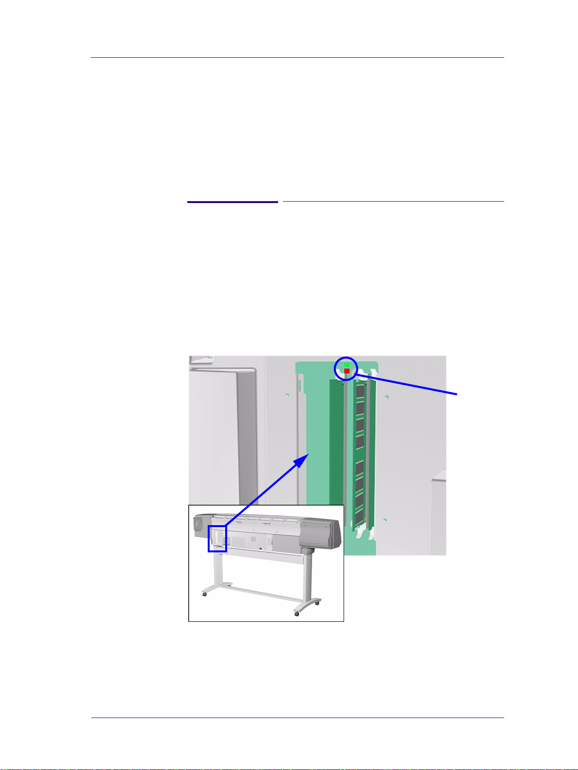
3. Remove the DIMM’s Cover (See ⇒ Page 8-73) and check the green
and red Status LED’s on the Main PCA. If they are both NOT lit,
replace the Power Supply Unit ⇒ Page 8-81.
Status
LED’s
4. Check that the Front-Panel Cable is correctly connected to the
Electronics Module. Also make sure that the Front-Panel Cable is
not damaged.
HP DesignJet 5000 Series Printers Service Manual
1-5
Page 18

Troubleshooting
ALL the Front-Panel LEDs are Lit but Nothing Else Happens
The BootROM DIMM is NOT correctly installed or is the wrong
type.
1. Power OFF the Printer from the back and disconnect the Power
Cord. Reseat the BootROM DIMM (looking from the rear of the
Printer, the first slot from the left - See
that it is installed correctly.
⇒ Page 8-73) making sure
2. If the problem persists replace the BootROM DIMM
⇒ Page 8-73.
Troubleshooting Media Jams/Printhead Crashes
NOTE If using HP Coated Media when problem occurred, please also
refer to Page 1-10.
The failure modes “media jam” and “head crash” are grouped
together because in many c ases a me dia ja m cause s the m edia to li ft
up into the carriage path and cause a head crash, thus causing many
media jam failures to be reported as head crashes.
1. Did the media jam occur when loading media?
n If the client has had media jams, it is common for pieces of media
to get stuck in the media path. Clear the media path.
NOTE When clearing a media jam, sometimes media is stuck in the
paper path. T o clear this, you must lift the media lever and insert
thicker media into the paper path to push out the media that is
still stuck there.
1-6
2. Is the customer using non-HP media?
n The use of non-HP media can easily be the cause of media jams
and head crashes (especially head crashes because HP media is
specially formulated to avoid cockle, one of the primary causes
of head crashes). If the media is not HP approved, advise the
customer to use HP media and check to see if the problem is now
solved.
3. The Carriage is at the incorrect height in relation to the Center
Platen. Adjust the carriage to the correct height ⇒ Page 5-18 and try
to load the media again.
4. Check that the Vacuum Fans work correctly - Refer to Page 1-9,
Problems with Vacuum .
HP DesignJet 5000 Series Printers Service Manual
Page 19

Troubleshooting
Troubleshooting Shutdowns
If a shutdown occurs, you will get the message “Switch Power Off”
followed by:
n Check Printhead Cleaner Path.
n Check Paper Path.
n Check Printhead Path (followed by (1), (2) or (3)).
A shutdown in each path will require different steps to resolve the
problem as explained as follows.
WARNING In each case, make sure that you power OFF the Printer be fore
attempting any procedures to resolve the problem.
Printhead Cleaner Path
1. Open the right door of the Printer and check for any visible
obstacles restricting the movement of Service Station. Manually
move the Service Station, checking for smooth and free movement.
Media Path
When a shutdown occurs in the Media path, you will get the
message “Switch Power Off / Check Media Path (*). The (*) will be
a number, which will give an indication on where the failure
occurred:
1. Open the Window and check for any visible obstacles restricting the
movement of the Drive Roller. If there is a wrinkled mass of media
inside the paper path, lift the Pinch wheels (using the Media Lever)
and clear the obstruction. If you cannot reach the media remove the
Entry Roller (⇒ Page 8-104) to gain better access.
2. If this shutdown happens at the end of a Roll of Media, it could be
because the media is stuck firmly to the Roll. Lift the Pinch wheels
(using the Media Lever) and pull the media clear.
3. Perform the Media Axis Test
Printhead Path
⇒ Page 4-12.
When a shutdown occurs in the Printhead path, you will get the
message “Switch Power Of f / Check Printhead Path (*). The (*) will
be a number, which will give an indication on where the failure
occurred:
1. Switch the Printer OFF from the rear and open the window.
HP DesignJet 5000 Series Printers Service Manual
1-7
Page 20

Troubleshooting
2. Look in the area where the Printer was printing at the time of the
jam, this is where the media is most likely to be jammed.
3. Raise the media load lever.
4. Carefully remove any of the jammed media which you can lift up
and out from the top of the Printer.
5. Carefully pull the rest of the roll or sheet down and out of the
Printer.
6. If you are using a roll of media, trim the media with a knife as
shown in the User’s Guide.
7. Reload the media.
8. Switch the Printer ON.
9. If there is some media left behind in the media path, loading paper
can become difficult. This can be cleared by loading a rigid paper
type through the Printer media path.
10. If you have image quality problems after a paper jam, this could
indicate that the Printheads have been moved from their correct
position in the Carriage. To correct this perform Printhead
Alignment - Refer to the User’s Guide.
PWM Shutdown (1) and Energy Shutdown (3)
1.
Clean Slider Rods and Apply Oil along the complete axis of the Slider
Rods with the User’s Slider Rods Lubrification Kit
applying the Oil, perform the Scan-Axis Test ⇒ Page
⇒
Page
9-8
. After
4-10 and check
that the values are within the given limit s .
2. Replace the Scan-Axis Motor ⇒ Page 8-53.
Velocity Shutdown (2)
1. Open the Window and check for any visible obstacles restricting the
movement of the Carriage Assembly. Try and move the Carriage
Assembly manually, checking for smooth and free movement.
2. Check that the Encoder Strip is clean. If necessary, clean the
Encoder Strip using a damp cloth.
1-8
HP DesignJet 5000 Series Printers Service Manual
Page 21

Troubleshooting
Problems with Vacuum
If you have problems loading either Roll or Sheet Media, then there
could be a problem with the Vacuum Fan or Booster Fan. To verify
if there really is a problem with Vacuum, try the following:
1. With the Printer ON, open the Window of the Printer and place a
sheet of HP High Gloss Photo Paper (must be D-Size), aligned with
the blue lines on the Center Platen. If the Vacuum holds the sheet in
place, and then loads it c orrectly, then the Fans function correctly. If
the Vacuum does not hold the sheet in place (no suction), then try
the following:
n Check that the holes in the Center Platen are NOT blocked.
n
Clean the Overdrive using the Platen Cleaning Utility ⇒ Page
n Check that the Vacuum and Booster Fans are installed correctly.
n Replace the Vacuum Fan ⇒ Page 8-96.
n Replace the Booster Fan ⇒ Page 8-101.
2. If the Vacuum held the sheet in place, but couldn’t correctly load it,
then there could be a problem with the Overdrive. In this case,
replace the Center Platen Assembly
⇒ Page 8-110.
9-9
.
Vacuum suction much lower at high altitudes
At altitudes above 2,000 meters, the vacuum force holding down the
media will be lower, therefore the media will not be held in place
properly causing:
n Ink Smearing on the Media.
n Printhead crashes against the Media.
n Cut Sheet loading problems (high probability).
n Roll Media loading problems (low probability).
To solve the problem, try the following:
n Using the “1.3 Altitude Setup” in the Service Utilities, set the
altitude to “1.3.2 2000 m or more” (see Altitude Setup 4-23).
HP DesignJet 5000 Series Printers Service Manual
1-9
Page 22

Troubleshooting
Printhead Crashes/Smears on High Density Prints Using Coated Media
High density prints can cause cockle mainly on HP Coated Media.
This causes two main problems:
1. Cockling in the borders - Because the Printer places too much ink
on the Coated Media, the borders of the print become raised,
causing the Printhead to crash against the media. To solve the
problem, try the following:
n Check in the Front Panel if print mode is Max. Quality. If it is
selected, then change print mode to Productivity to reduce ink
density.
n Change the paper margins to “Extended” in the Printer Setup
menu/Page Format/Margins or in the Driver. If the customer is
printing PostScript images, send them a PPD file containing the
extended margins.
2. Cockling within the print - If the Printer places too much ink within
the print, the media starts to ripple, causing the Printhead to smear
against the media. To solve the problem, try the following:
n Check in the Front Panel if print mode is Max. Quality. If it is
selected, then change print mode to Productivity to reduce ink
density.
n Never use HP Coated Media for High Density prints. As a
substitute use HP Heavy Weight Coated or Heavy W e ight Coated
(Economy) Media.
Color differences in different HP DesignJet Printers
Color differences between one image printed on the HP DesignJet
5000 Series and the rest of the DesignJet platforms are due to the
different chemistry of the 5000 series inks compared with the rest of
the inks for other printers. This color variability among different HP
DesignJet Series Printers has been always present. You can try to
achieve consistent colors with the following:
n Select the same color emulation settings in your Postscript Driver
as the one used by the printer you want to emulate.
n Select the correct Ink Emulation from the Printer Setup Menu/
Internal RIP Settings.
1-10
HP DesignJet 5000 Series Printers Service Manual
Page 23

Troubleshooting
Banding at variable extreme environmental conditions
The Accuracy Calibration has been done at normal environmental
conditions, therefore printing in extreme environmental conditions
will cause banding because the advance of the Drive Roller does not
correspond to the same conditions that the calibration was done in.
To solve the problem, try the following:
n Perform the Accuracy Calibration in the new environmental
conditions (Refer to the User’s Guide - Media Solutions).
Banding with unsupported Media
The Accuracy Calibration has not been done for the Media now
loaded. Banding may occur because the advance of the Drive Roller
does not correspond to the same conditions that the calibration was
done in. To solve the problem, try the following:
n Select the Media loaded in the “Media Options” menu and
perform the Accuracy Calibration (Refer to the User’s Guide Media Solutions).
Banding due to Ink Cartridge replacement while printing
A user has removed the Ink Cartridge while the Printer was printing,
which has caused the Printer to stop. If the user does not replace the
Ink Cartridge immediately, when the Printer starts to print again, a
band will appear in the position where the pri nting restarte d. This is
because the wet ink interacts with the dried ink on the media
causing the band to appear. To solve the problem, try the following:
n Do NOT remove the Ink Cartridge while the Printer is Printing.
Only replace/remove Ink Cartridges in between Prints.
n If the Ink Cartridge was replaced due to the “Empty” status on the
Front Panel, then advise the customer to replace the Ink Cartridge
when the “Very Low” status is showing on the Front Panel.
HP DesignJet 5000 Series Printers Service Manual
1-11
Page 24

Troubleshooting
Hue shift on HP Colorfast Adhesive Vinyl media
Under high humidity conditions (approx. >65%) the colors tend to
fade over time, particularly colors that require Magenta. To solve
the problem, try the following:
n Reduce the level of humidity (<65%) that the Printer is working
in. To find the humidity level, print the Service Configuration
Print (Printer Setup Menu / Utilities / Test prints / Service config).
n Laminate the prints.
Black Smearing on HP Photo Imaging Gloss
Narrow black lines can smear on this type of media, particularly if
the lines are narrow and have white gaps in between them. Try the
following:
n Increase the Dry Time using the Front Panel (Refer to the User’s
Guide).
n Laminate the prints.
Magenta Bleeding on HP Photo Imaging Gloss when using the Take Up Reel
Under high humidity conditions (approx. >70%) this media reduces
its capacity to absorb Magenta because of this color’s particular
characteristics. When an area fill with magenta is printed and then
rolled onto the Take Up Reel the ink that is not completely dry
moves laterally on the media. To solve the problem, try the
following:
n Reduce the level of humidity (<70%) that the Printer is working
in. To find the humidity level, print the Service Configuration
Print (Printer Setup Menu / Utilities / Test prints / Service config).
n Increase the Dry Time using the Front Panel (Refer to the User’s
Guide).
n Do not use the Take Up Reel or Bin for this media when humidity
levels are high.
1-12
HP DesignJet 5000 Series Printers Service Manual
Page 25

Troubleshooting
Loss of Gloss on HP Photo Imaging Gloss when using the Take Up Reel
Under high humidity conditions (approx. >70%) the polymer chain
in the coating of this media relaxes and the drying rate decreases. If
the printed media is rolled onto a Take Up Reel or is covered by
another print, the contact between the two surfaces could cause
blotches in the gloss. Try the following:
n Reduce the level of humidity (<70%) that the Printer is working
in. To find the humidity level, print the Service Configuration
Print (Printer Setup Menu / Utilities / Test prints / Service config).
n Increase the Dry Time using the Front Panel (Refer to the User’s
Guide).
n Do not use the Take-Up Reel or Bin for this media when
humidity levels are high.
Dry Cockle on High Density Prints Using Paper Based Media
High density prints can cause dry cockle mainly on Paper Based
Media.
To solve the problem do the following:
n Use the Take Up Reel and Take Up Reel deflectors.
n Set the Printer to Productivity mode to reduce the ink density.
n Select Coated media modes.
If the problem persists, try the following:
n Laminate the prints.
n Use a heavier media that is more suitable to high ink density,
such as HP Paper based Semi-Gloss or HP Poster Paper.
HP DesignJet 5000 Series Printers Service Manual
1-13
Page 26

Troubleshooting
Wrinkles and scratches (cockle) when using HP Coated and Heavyweight Coated Media.
Images may be damaged if prints are not handled with care,
particularly when handling wide plots. This can happen when
images are placed on top of one another and there is movement
between them, causing friction and loss of ink from the surface if it
is not completely attached. Also, if plots are rolled up wrinkles can
occur. To avoid this problem try the following:
n Always handle plots with care.
n Use of the Take-Up Reel eliminates handling and avoids
wrinkles.
n Use heavier media.
n Select faster print modes such as Heavyweight Coated
(Economy) for Media selection and/or Productivity Print mode.
n If damage is slight, Lamination will help towhead’ defects.
n Use of Fixative Sprays immediately after printing may protect the
image.
Worm marks (cockle) on part of plots on paper based media
At high temperatures and under dry conditions worm marks may
occur on initial parts of plots when printing solid fill areas in
medium tone colors. Try the following:
n Advance the media manually by 15 mm.
n Select Heavy Coated for Media setting.
n Select Productivity mode to reduce ink density.
1-14
HP DesignJet 5000 Series Printers Service Manual
Page 27

Troubleshooting
Drying Time Too Long for HP Studio Canvas
Under conditions of high humidity (> 70%) HP Studio Canvas
retains a high amount of water and takes too long to dry, also
creating problems in using the Take-Up Reel and Bin. To solve the
problem try the following:
n Reduce the level of humidity (<70%) that the Printer is working
in. To find the humidity level, print the Service Configuration
Print (Printer Setup Menu / Utilities / Test prints / Service config).
n Increase the drying time using the Front Panel settings (Refer to
the User’s Guide).
n Do not use the Take-Up Reel or Bin under conditions of high
humidity.
Media Skew when Printing a Banner Plot
When printing banners, media skew occurs. This is particularly
noticeable in the first plot when media is not perfectly aligned. To
solve this problem do the following:
n Use extended margins for banner plots (Refer to the User’s
Guide).
HP DesignJet 5000 Series Printers Service Manual
1-15
Page 28

Troubleshooting
Solving Media-Handling Problems
NOTE HP Designjet Printers minimum media size is A3 in portrait
mode.
The Front Panel Keeps Indicating that Media Is Misaligned or
Incorrectly Positioned
Roll media n The roll may be loaded the wrong way. The paper should load
over the roll toward you.
n The media may be crumpled or warped or have irregular edges.
n The paper may be loaded at an angle. The right-hand edge must
be parallel to the blue line on the paper entry roller.
WARNING Ensure that the paper is wrapped tightly on the roll. This is a
very important step to remember because if this is not done, the
media may be loaded at an angle, causing the media to be
rejected.
n Perform the manual alignment procedure (Refer to the User’s
Guide).
n Check that the paper is correctly loaded onto the spindle.
Sheet media n It must be loaded with the right-hand edge against the blue
perforated line on the Printer.
n Align the media against the trailing edge coming out of the
Printer.
n The media may be crumpled or warped or may have irregular
edges.
n If you are using hand-cut media, the edges may not form a right-
angle or they may be rough. Do not use hand-cut media. Use only
purchased sheet media.
n If the media you are trying to load is very slippery, hold the
media with both hands, and gently push the media into the Printer
until it buckles upwards in the middle, this will help the P rinter to
load it.
n If the Overdrive is covered in dust, it will have problems picking
up the sheet media during the load process. Clean the Overdrive
using the Platen Cleaning Utility ⇒ Page 9-7.
Prints Do Not Stack
Properly in the
Media Bin
n The Printer may be too close to the end of the roll. The natural
curl near the end of the roll can cause stacking problems. Load a
new roll or remove prints manually as they are completed.
1-16
n If you are mixing prints or nesting sets of several different sizes,
you may have stacking problems because of the different sizes of
media in the bin.
HP DesignJet 5000 Series Printers Service Manual
Page 29
Troubleshooting
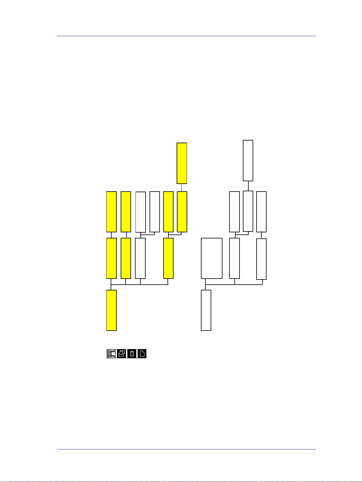
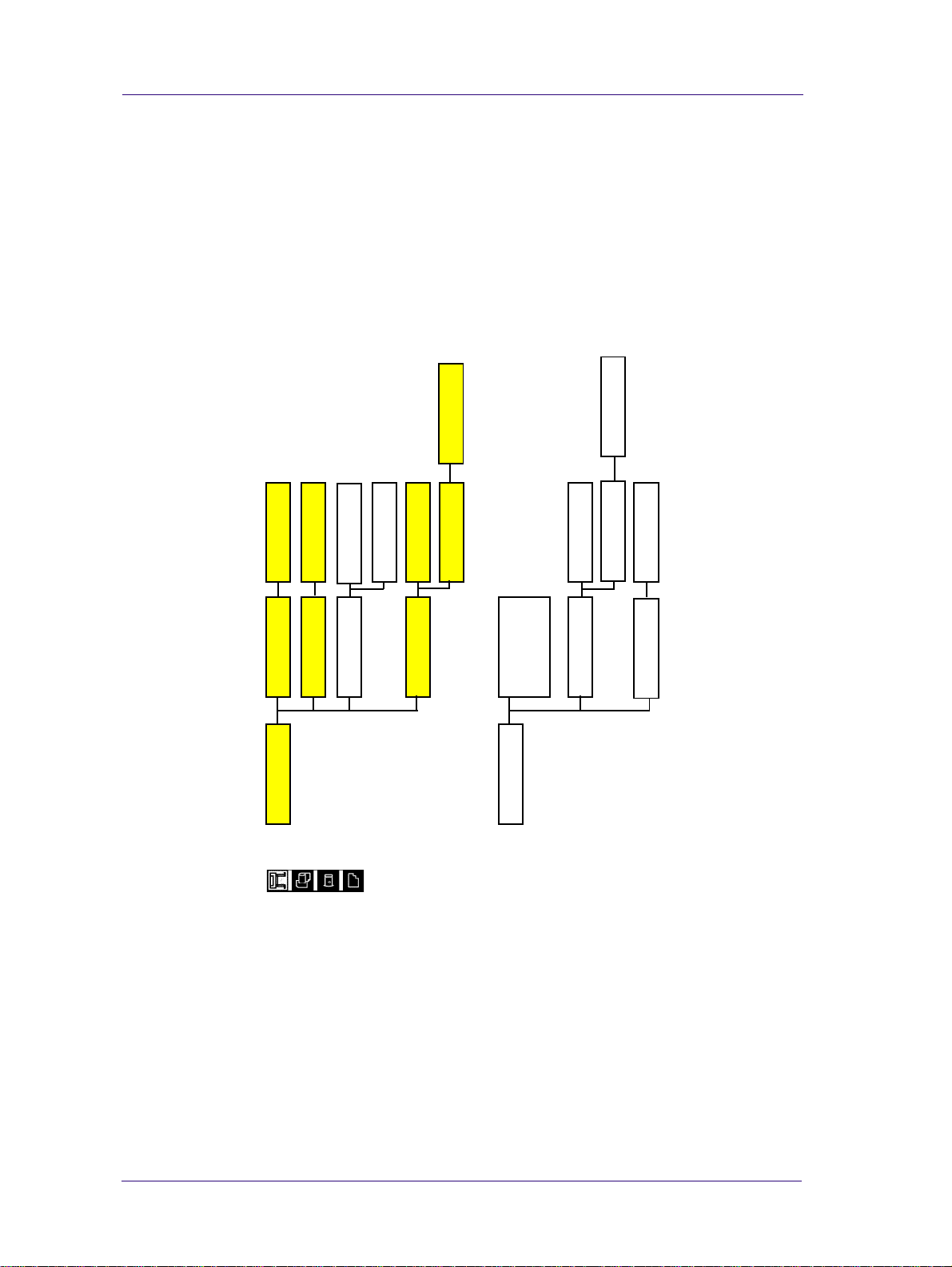
How to Navigate through the Front Panel Menus
Shaded boxes always appear in the front panel. White boxes appear
only in Full menu mode.
Printer Setup Options
NO, YES
TUR installed
Device Setup
255 - 2, 1 min
Postscript,
On, Off
Cutter
Automatic
Automatic,
Manual
None
HP-GL/2, CALS/G4
Language
Drying time
No I/O Card found,
I/O Setup
Card ID,
Card ID,
Card Setup
Reset card
Advanced
Configuration
Card Setup
0.5 min ... 30 min
I/O timeout
HP DesignJet 5000 Series Printers Service Manual
1-17
Page 30
Troubleshooting
@ - Postscript models only
255 - 2, 1 min
NO, YES
On, Off
Cutter
TUR installed
Device Setup
Postscript, @Automatic
Automatic,
Manual
HP-GL/2, CALS/G 4
Language
None
Drying time
Card ID,
Card ID,
Card Setup
No I/O Card found,
I/O Setup
Reset card
Advanced
Configuration
Card Setup
0.5 min ... 30 min
I/O timeout
2
1-18
HP DesignJet 5000 Series Printers Service Manual
Page 31

Troubleshooting
Create Pattern
Measure Pattern
Restore factory
Recalibrate
Auto, Manual
Yes , N o
Short, Full
Print usage, View usage
Printhead alignment
Accuracy
Color Calibration
Print Quality
Usage report
Service config.
HP-GL/2 config.
Ram present, Service ID
Hark disk, Co de Rev.
Up, Down
PS Code Rev, PS Font code
Track Media Length
Utilities
Usage
Menu Mode
Calibrations
Reset Web Svr Passwd
Test print
Statistics
Default Menu
Clean Platen
Display Contr ast
Lens Maintenance
HP DesignJet 5000 Series Printers Service Manual
1-19
Page 32

Troubleshooting
255 - 1, 0
0.13mm _ 12.0mm
Color
Width
Pen number 0 _ 15
Pen number 0 _ 15
Factory
Palette A,
Palette B,
Palette A
Software, factory.
Palette
HP-GL/2 Settings
Palette B
Define Palette
Off, On
Merge
1-20
HP DesignJet 5000 Series Printers Service Manual
Page 33

Native sRGB
Apple RGB
Adobe RGB
Color Match RGB
Native, Euroscale,
SWOP, TOYO @
Troubleshooting
Width, Length
99 .. 1, 0
@ - Postscript models only
Move to top,
Statistics
Copies
99 .. 2, 1 min
Delete page
#...
RGB @
CMYK @
Off, On
Optimized, immediately
After processing
Start Printing
Ink Emulation @
Internal RIP S ettings
Color calibration
Off, On
Black Replacement
Off, On
100%..419%, Fit to Page @
PS Scale
Enhanced res
ASCII
Binary
Software
PS Encoding
Off
In order
Nest
Queue mgmt
Queueing & Nesting
HP DesignJet 5000 Series Printers Service Manual
1-21
Page 34

Troubleshooting
1.0x1.4m,
42x59in., 44x62in.,
Inked area,
Software
Size
Page format
Over A2, Over A1
54x76in., 60x100in.
1.2x1.7m, 52x73in.,
Oversize
Extrawide
Best JIS B
Best ANSI,
Best ISO A,
ANSI A .. E
JIS B4 .. B1
Best ARCH
ARCH A .. E1
JIS
ARCH
ANSI
ISO A4 .. A0
ISO
0 .. 270
Normal, Extended
Margins
Rotate
30 .. 5, 0 mm
On, OffMirroring
Manual
Automatic
Nest Spacing
Menu
Samples, Palette
Demos
1-22
HP DesignJet 5000 Series Printers Service Manual
Page 35

Media Options
Troubleshooting
Vendor Name
Type of Media
Width
Printable Area
Profile Revision
Roll/Sheet Info.
HW Coated (Economy)
HW Coated
Coated Paper
Photo Imaging Gloss
Colorfast Vinyl
Paper Semi-Gloss
Poster Paper
Studio Canvas
*HW Coated (Economy)
*HW Coated
*Coated Paper
*Photo Imaging Gloss
*Colorfast Vinyl
*Paper Semi-Gloss
Media Selection
Delete Media
Move Media
Yes, No
and more.......
TUR Loaded=
*Poster Paper
*Studio Canvas
and more.......
Yes, No
Form Feed & Cut
HP DesignJet 5000 Series Printers Service Manual
1-23
Page 36

Troubleshooting
Ink Cartridge Info
HP No. 81 Ink Cartridge
Ink Level
Capacity
Part Number
Manufacture Date
Light Cyan cart Info
Light Magenta cart Info
Yellow cart. Info
Cyan cart Info
Magenta cart Info
Yes, No
Replace Ink Cartridge
Black cart Info
1-24
HP DesignJet 5000 Series Printers Service Manual
Page 37

Printhead Info
Troubleshooting
Printhead Info
Recover Printheads
Replace Printheads
Light Cyan Info
Light Magenta Info
Yellow Info
Cyan Info
Magenta Info
Black Info
All Printheads
Cyan
Magenta
Yellow
Black
Light C
Light M
Yes, No
HP DesignJet 5000 Series Printers Service Manual
1-25
Page 38

Troubleshooting
Service Configuration Print
The Service Configuration Print is a useful tool for troubleshooting
the Printer. The Service Configuration Print contains the following
information about the Printer:
n General Configuration
n Printhead Info.
n Ink Cartridge Info.
n Operating Conditions.
n Calibrations.
n Maintenance.
n I/O Configuration.
How to Print the Service Configuration Print
1. Load media (Roll media or at least an A0 Sheet) into the Printer.
2. Once the message “Ready” is displayed on the front-panel, scroll to
the “Printer Setup Options” icon and press the Enter key.
Ready
Roll
Hewlett Packard
Photo Imaging Gloss
Ink OK
Printheads OK
Printer Setup Options
3. Once inside the “Printer Setup Options” menu, use the Arrow keys
to scroll to the “Utilities” menu display and press the Enter key.
Printer setup options
Device setup...
I/O setup...
Utilities...
Internal RIP settings...
Queueing & Nesting...
HP-GL/2 settings...
Top
Back
↑
↓
Enter
Make Selection
Press Enter
1-26
HP DesignJet 5000 Series Printers Service Manual
Page 39

Troubleshooting
4. Once inside the “Utilities” menu, use the Arrow keys to scroll to the
“Test prints” menu display and press the Enter key.
Utilities
Utilities
Display Contrast ...
Calibrations ...
Reset WebAccess paswd
Contrast ...
Test Prints
Statistics ...
...
Default menu
Test Prints ...
Display contrast . . .
Top
Back
↑
↓
Enter
Press Up
and Enter
5. Use the Arrow keys to scroll to “Service Config.” and press the
Enter key to print the Service Configuration Print.
How to Use the Service Configuration Print
The Service Configuration Print is divided into 7 different areas
where you can find information to troubleshoot the Printer.
n General Configuration - In this area you can find information
regarding the general configuration of the Printer, for example,
the firmware version, amount of memory installed or the capacity
of the Hard Disk Drive.
n Printhead Info - In this area you can find all the information
regarding the Printheads, for example, the part number, the
manufacturing date or the number of times a certain Printhead
has been inserted in the carriage. This information is useful for
troubleshooting Printhead problems and even knowing if the
Printheads have been used with Non-HP Ink Cartridges.
n Cartridge Info - In this area you can find all the information
regarding the Ink Cartridges, for example, the part number, the
manufacturing date or the ink level. This area also shows you if
the customer is using Non-HP Ink Cartridges.
n Operating Conditions - In this area you can find the level of
humidity and the temperature that the Printer is working in.
n Calibrations - In this area you can find information on certain
calibrations that have been performed on the Printer. It will also
tell you if a required calibration was performed or not.
n Maintenance - In this area you can find information relating to
maintenance, for example, the number times the Printer has been
powered ON, the number of Carriage cycles or the last System
Error Code that was triggered.
n I/O Configuration - In this area you can find information on the
configuration of the JetDirect Card.
HP DesignJet 5000 Series Printers Service Manual
1-27
Page 40

Troubleshooting
1-28
HP DesignJet 5000 Series Printers Service Manual
Page 41

System Error Codes 2
System Error Codes 2-2
01002D (Non-Continuable) 2-4
010023 (Non-Continuable) 2-4
010040 2-4
010041 2-5
010042 2-5
010090 (Continuable) 2-6
010091 (Continuable) 2-6
010092 (Continuable) 2-6
011000 2-6
06030C 2-7
0A0000 2-7
0A0010 2-8
0A0030 2-8
0A0040 2-8
0A0050 (Non-Continuable) 2-9
0A0060 (Non-Continuable) 2-9
0A0070 (Continuable) 2-9
0C0030 2-10
0C0032 (Continuable) 2-10
0C0040 2-10
0C1001 2-11
0D0000 (Continuable) 2-11
0D0002 (Continuable) 2-11
0FXXXX (Non-Continuable) 2-11
System Error Codes During Initialization 2-12
HP DesignJet 5000 Series Printers Service Manual
2-1
Page 42

System Error Codes
System Error Codes
Introduction
NOTE Before troubleshooting System Errors, if possible, repeat the
procedure performed when the error was reported.
NOTE When reporting the System Error Code, make sure that you
supply the full Error Code and the firmware version (displayed
during the initialization process when powering ON the Printer
or available in the User’s Printer Setup
menu).
The following pages contain a list of System Error Codes and their
respective descriptions and recommended corrective actions. Only
try one recommended action at a time and check if the Error Code
has disappeared.
⇒ Utilities ⇒ St at i st i c s
System Error Codes consist of two groups of alphanumerics:
[XXXXXX]-[YYYYZZZZ]
The first set of 6 alphanumeric characters consists of the System
Error and the second set of 8 digits, when present, refer to the
internal error data.
NOTE If the YYYY digits in the second set of 8 characters are zero
[0000ZZZZ], this indicates a LAN Card System Error. The last
four digits [ZZZZ] of the Error Code must be reported to the
vendor support organization:
n For HP JetDirect Cards, this error code must be reported to
the iIPS Division Support.
n For 3rd party LAN Cards, the HP support organization s hould
communicate to the customer that they should address it
through the 3rd party vendor support structure.
2-2
HP DesignJet 5000 Series Printers Service Manual
Page 43

System Error Codes
If you have an error code which is not documented in this Service
Manual or you have an error which you cannot resolve, then report
the error to the HP Response Center or the nearest HP Support
Office. When reporting the error, have the following information
ready:
n Model and Serial Number of the Printer.
n Which firmware revision the Printer is using.
n The complete error number.
n The Service Configuration Print if possible ⇒ Page 1-26.
The Current configuration sheet.
n
n Which software application the customer is using (name, version,
etc.).
Continuable and Non-Continuable Error Codes
Some of the Error Codes are continuable, which means you can
press Enter on the front-panel and continue working with the
Printer. Non-Continuable Error Codes do not allow you to continue
working with the Printer , in this case power the Printer OFF and ON
again and see if the System Error disappears. If the Error Code
reappears, then the Printer requires an on-site visit in order to
resolve the problem.
NOTE Even though the customer can continue working with a
Continuable Error Code, an on-site visit should still be planned
to troubleshoot the problem.
HP DesignJet 5000 Series Printers Service Manual
2-3
Page 44

System Error Codes
System Error: 01002D (Non-Continuable)
Problem
Description:
Corrective Action: Try the following:
System Error: 010023 (Non-Continuable)
Problem
Description:
Corrective Action: n Replace the Main PCA ⇒ Page 8-77.
The Main PCA cannot communicate with the Carriage.
n Check the Trailing Cable is connected correctly.
n Replace the Trailing Cable ⇒ Page 8-36.
n Replace the Carriage Assembly ⇒ Page 8-46.
EEROM Test failure.
NOTE After replacing the Main PCA, make sure you perform the
Backup EEROM ⇒ Page 4-31, making sure that you select
"Main PCA" when prompted.
System Error: 010040
Problem
Description:
Error in Paper-axis Encoder quadrature.
Corrective Action: Try the following:
n Check that the Paper-Axis Motor cable is NOT broken or
damaged.
n Check that the Paper-Axis Motor cable is correctly connected.
n Replace the Paper-Axis Motor ⇒ Page 8-98.
n If the Error Code continues, replace the the Main PCA ⇒ Page 8-
77.
WARNING Only replace one component at a time and check if the error has
gone before replacing another component. Using this procedure
you will be able to determine exactly which component failed.
2-4
HP DesignJet 5000 Series Printers Service Manual
Page 45

System Error: 010041
System Error Codes
Problem
Description:
Corrective Action: Try the following:
Error in Scan-axis Encoder quadrature.
n Check that the Encoder Strip is NOT broken or damaged.
n Replace the Encoder Strip ⇒ Page 8-34.
n Replace the Carriage Assembly ⇒ Page 8-46.
n If the Error Code continues, replace the Main PCA ⇒ Page 8-77.
WARNING Only replace one component at a time and check if the error has
gone before replacing another component. Using this procedure
you will be able to determine exactly which component failed.
System Error: 010042
Problem
Description:
Corrective Action: Try the following:
Error in Service Station-axis Encoder quadrature.
n Check that the Service Station Encoder-Cable is NOT broken or
damaged.
n Check that the Service Station Encoder-Cable is correctly
connected.
n Replace the Service Station ⇒ Page 8-65.
n If the Error Code continues, replace the Main PCA ⇒ Page 8-77.
WARNING Only replace one component at a time and check if the error has
gone before replacing another component. Using this procedure
you will be able to determine exactly which component failed.
HP DesignJet 5000 Series Printers Service Manual
2-5
Page 46

System Error Codes
System Error: 010090 (Continuable)
Problem
Description:
Corrective Action: Try the following:
Error in Paper-axis Motor Encoder
n Check that the Paper-Axis Motor cable is NOT broken or
damaged.
n Check that the Paper-Axis Motor cable is correctly connected.
n Replace the Paper-Axis Motor ⇒ Page 8-98.
n If the Error Code continues, replace the Main PCA ⇒ Page 8-77.
WARNING Only replace one component at a time and check if the error has
gone before replacing another component. Using this procedure
you will be able to determine exactly which component failed.
System Error: 010091 (Continuable)
Problem
Description:
Corrective Action: Refer to System Error Code 010090.
Error in Paper-axis Motor Encoder
System Error: 010092 (Continuable)
Problem
Description:
Corrective Action: Try the following:
Mark Encoder position not detected on Drive Roller.
n Replace the Lens Cover ⇒ Page 9-5.
n Clean the Mark Encoder on the Drive Roller using the Turn
DRIVE ROLLER Utility ⇒ Page 4-18.
System Error: 011000
Problem
Description:
Corrective Action: Power the Printer OFF and ON again using the Power Switch at the
NIB Crash.
back of the Printer.
2-6
HP DesignJet 5000 Series Printers Service Manual
Page 47

System Error: 050001 (Continuable)
System Error Codes
Problem
Description:
Corrective Action: Try the following:
Lens has problems reading the Mark Encoder on the Drive Roller.
n Clean the Mark Encoder on the Drive Roller using the Turn
DRIVE ROLLER Utility ⇒ Page 4-18
n Replace the Lens Cover Assembly ⇒ Page 9-5.
System Error: 06030C
Problem
Description:
Corrective Action: Try the following:
Bad Line Sensor.
n Replace the Carriage Assembly ⇒ Page 8-46
n Replace the Trailing Cable ⇒ Page 8-36.
n Replace the Main PCA ⇒ Page 8-77.
WARNING Only replace one component at a time and check if the error has
gone before replacing another component. Using this procedure
you will be able to determine exactly which component failed.
System Error: 0A0000
Problem
Description:
Corrective Action: Try the following:
APS Failure.
n Check all the cables of the APS and make sure they are correctly
connected and are NOT damaged.
n Check all the tubes of the APS and Tubes System and make sure
they are correctly connected and are NOT pinched or damaged.
n Check that the Air Tube from the APS is correctly connected to
the Tubes System.
n Replace ONE Ink Cartridge at a time, checking if the System
Error Code disappears.
n Faulty APS. Replace the APS ⇒ Page 8-63.
WARNING Only replace one component at a time and check if the error has
gone before replacing another component. Using this procedure
you will be able to determine exactly which component failed.
HP DesignJet 5000 Series Printers Service Manual
2-7
Page 48

System Error Codes
System Error: 0A0010
Problem
Description:
Corrective Action: Refer to System Error Code 0A0000.
System Error: 0A0030
Problem
Description:
Corrective Action: Try the following:
APS Failure.
Problem in Depressurizing Air System.
n Check the APS for any signs of Ink. Also inspect ALL Ink
Cartridges for any signs of leaking (the bottom valve of the Ink
Cartridge will contain ink).
n If there is ink leakage, replace ALL Ink Cartridges, the APS ( ⇒
Page 8-63) and the Tubes System ( ⇒ Page 8-25).
WARNING Only replace one component at a time and check if the error has
gone before replacing another component. Using this procedure
you will be able to determine exactly which component failed.
System Error: 0A0040
Problem
Description:
Corrective Action: Try the following:
APS Failure.
n Check all the cables of the APS and make sure they are correctly
connected and are NOT damaged.
n Check all the tubes of the APS and Tubes System and make sure
they are correctly connected and are NOT pinched or damaged.
n Replace ONE Ink Cartridge at a time, checking if the System
Error Code disappears.
n Faulty APS. Replace the complete APS ⇒ Page 8-63.
WARNING Only replace one component at a time and check if the error has
gone before replacing another component. Using this procedure
you will be able to determine exactly which component failed.
2-8
HP DesignJet 5000 Series Printers Service Manual
Page 49

System Error: 0A0050 (Non-Continuable)
System Error Codes
Problem
Description:
Corrective Action: Try the following:
The Printer has detected a leak in the Tubes System before the life
of the System.
n Check for ink in the Ink Leak Detector and, if present, replace the
complete Tubes System ⇒ Page 8-25.
n The Ink Leak Detector could have been trigggered due to
condensation in the Printer. Power OFF the Printer and allow the
Printer to dry for 15 minutes. Power ON and check if the System
Error Code has disappeared.
n Replace the ISS PCA ⇒ Page 8-84.
WARNING Only replace one component at a time and check if the error has
gone before replacing another component. Using this procedure
you will be able to determine exactly which component failed.
System Error: 0A0060 (Non-Continuable)
Problem
Description:
The Printer has detected a leak in the Tubes System after the life of
the System.
Corrective Action: Refer to System Error Code 0A0050.
System Error: 0A0070 (Continuable)
Problem
Description:
Corrective Action: Try the following:
The Backup EEROM contents stored in the Hard Disk Drive are not
consistent with the ones required by the firmware.
n Perform Backup EEROM ⇒ Page 4-31 and ALL calibrations.
Perform EEROM Setup ⇒ Page 4-24 to reconfigure the Printer.
HP DesignJet 5000 Series Printers Service Manual
2-9
Page 50

System Error Codes
System Error: 0C0030
Problem
Description:
Corrective Action: Try the following:
Drop Detector Failure.
n Check that the Drop Detector Cable is NOT broken or damaged.
n Check that the Drop Detector cable is correctly connected to the
Service Station Cable.
n Remove the Drop Detector and make sure that there are no
obstacles inside which are blocking the sensor.
n Replace the Drop Detector Assembly ⇒ Page 8-68.
n If the System Error Code continues, replace the Main PCA ⇒
Page 8-77.
WARNING Only replace one component at a time and check if the error has
gone before replacing another component. Using this procedure
you will be able to determine exactly which component failed.
System Error: 0C0032 (Continuable)
Problem
Description:
Drop Detector not Calibrated for all Printheads.
Corrective Action: Try the following:
n Perform the Service Station Calibration ⇒ Page 5-11.
n Replace the Drop Detector Assembly ⇒ Page 8-68.
n If the System Error Code continues, replace the Main PCA ⇒
Page 8-77.
WARNING Only replace one component at a time and check if the error has
gone before replacing another component. Using this procedure
you will be able to determine exactly which component failed.
System Error: 0C0040
Problem
Description:
Corrective Action: Try the following:
Error in Printhead Drop Detection.
n Recover the Printheads ⇒ Page 6-15.
n Replace the Drop Detector ⇒ Page 8-68.
2-10
HP DesignJet 5000 Series Printers Service Manual
Page 51

System Error: 0C1001
System Error Codes
Problem
Description:
Corrective Action: Try the following:
Primer Shutdown Error.
n Check that the Primer Stepper-Motor Cable is NOT broken or
damaged and that the Primer Arm moves freely from side to side.
n Replace the Service Station ⇒ Page 8-65.
n If the Error Code continues, replace the Main PCA ⇒ Page 8-77.
WARNING Only replace one component at a time and check if the error has
gone before replacing another component. Using this procedure
you will be able to determine exactly which component failed.
System Error: 0D0000 (Continuable)
Problem
Description:
Corrective Action: n Download a media profile for the ink type being used.
System Error: 0D0002 (Continuable)
Problem
Description:
No Media Profiles Available.
Insufficient Memory to Initialize HPGL2/RTL.
Corrective Action: n The minimum memory required is 96 Mbytes so verify memory
installed on the printer using the Statistics menu (refer to the
User’s Guide).
System Error: 0FXXXX (Non-Continuable)
Problem
Description:
Corrective Action: Try the following:
A Firmware Error has occurred.
n Power OFF and ON using the Printer Power Switch.
n Report the error to the HP Response Center or the nearest HP
Support Office. Have the following information ready:
n Model and Serial Number of the printer.
n Which firmware revision the printer is using (displayed during
Printer initialization when powering ON).
n The complete error number.
n The Service Configuration Print if possible ⇒ Page 1-26.
n
The Current configuration sheet.
n
Which software application the customer is using (name, version, etc.).
HP DesignJet 5000 Series Printers Service Manual
2-11
Page 52

System Error Codes
System Error Codes During Initialization
The following System Error Codes will only appear during the
Initialization process when you power ON the Printer.
System Error: 050000 (Continuable)
Problem
Description:
Corrective Action: Try the following:
Lens has problems reading the Mark Encoder on the Drive Roller.
n Clean the Mark Encoder on the Drive Roller using the Turn
DRIVE ROLLER Utility ⇒ Page 4-18
n Replace the Lens Cover Assembly ⇒ Page 9-5.
System Error: 0B0000
Problem
Description:
Corrective Action: Try the following:
Bad Ambient Temperature measured.
n Make sure that the Ambient temperature is within the allowed
range (between 0 and 55 Degrees Centigrade).
n Replace the Main PCA ⇒ Page 8-77.
System Error: 0B0001
Problem
Description:
Corrective Action: Replace the Main PCA ⇒ Page 8-77.
2-12
Bad Humidity read.
HP DesignJet 5000 Series Printers Service Manual
Page 53

System Error: 0B0002
System Error Codes
Problem
Description:
Corrective Action: Try the following:
Bad IDS pressure read.
n Check that the cable from the Ink Supply Station (ISS) PCA to
the Ink Supply Station is correctly connected.
n Check that the Air Pressurization System Sensor Cable is
correctly connected and is NOT damaged.
n Check all the tubes of the APS and make sure they are NOT
pinched or damaged.
n Faulty APS. Replace the APS ⇒ Page 8-63.
n If the error code continues, replace the Main PCA ⇒ Page 8-77.
WARNING Only replace one component at a time and check if the error has
gone before replacing another component. Using this procedure
you will be able to determine exactly which component failed.
System Error: 0B0003
Problem
Description:
ADC0 Internal channels check Failure.
Corrective Action: Replace the Main PCA ⇒ Page 8-77.
System Error: 0B0004
Problem
Description:
Corrective Action: Try the following:
APS Failure.
n Check that the cable from the Ink Supply Station (ISS) PCA to
the Ink Supply Station is correctly connected.
n Faulty APS. Replace the APS ⇒ Page 8-63.
n If the error code continues, replace the Main PCA ⇒ Page 8-77.
WARNING Only replace one component at a time and check if the error has
gone before replacing another component. Using this procedure
you will be able to determine exactly which component failed.
HP DesignJet 5000 Series Printers Service Manual
2-13
Page 54

System Error Codes
System Error: 0B0005
Problem
Description:
Corrective Action: Try the following:
APS Failure.
n Check that the cable from the Ink Supply Station (ISS) PCA to
the Ink Supply Station is correctly connected.
n Faulty APS. Replace the APS ⇒ Page 8-63.
n If the error code continues, replace the Main PCA ⇒ Page 8-77.
WARNING Only replace one component at a time and check if the error has
gone before replacing another component. Using this procedure
you will be able to determine exactly which component failed.
System Error: 0B0006
Problem
Description:
Corrective Action: Try the following:
The Trailing Cable has been incorrectly connected.
n Power the Printer OFF disconnect the T railing Cable. Replace the
Trailing Cable if the ends are not flat or are damaged. Reconnect
the Trailing Cable correctly, making sure it is pushed in firmly
(refer to the instructions on page ⇒ Page 8-36). Power ON the
Printer and check if the Error Code has disappeared.
n If the Error Code continues, replace the Main PCA ⇒ Page 8-77
taking care when connecting the Trailing Cable.
System Error: 0B0007
Problem
Description:
Corrective Action: Try the following:
Unable to detect Vacuum Fan.
n Make sure that the Vacuum Fan is connected correctly to the
Main PCA.
n
Turn the Printer OFF and disconnect the Vacuum Fan from the
Main PCA. Connect a
power ON the Printer. If the
without any Error Codes then remove the
the Printer and install the
n If the New Vacuum Fan does not function correctly either, then
replace the Main PCA ⇒ Page 8-77.
New
Vacuum Fan to the Main PCA and
New
Vacuum Fan functions correctly
Old
Vacuum Fan from
New
one.
2-14
HP DesignJet 5000 Series Printers Service Manual
Page 55

System Error: 0B0008
System Error Codes
Problem
Description:
Corrective Action: Try the following:
Unable to detect Cooling Fan.
n Make sure that both Cooling Fans are correctly connected to the
Power Supply Unit.
n Replace the Main PCA ⇒ Page 8-77.
System Error: 0B0009
Problem
Description:
Corrective Action: Try the following:
Unable to detect Aerosol Fan (in the Right Cover).
n Make sure that the Aerosol Fan is connected correctly to the
Main PCA.
n
Turn the Printer OFF and disconnect the Aerosol Fan from the
Main PCA. Connect a
Right Cover) to the Main PCA and power ON the Printer. If the
New
Aerosol Fan functions correctly without any Error Codes
then remove the
New
one.
n If the New Aerosol Fan does not function correctly either, then
replace the Main PCA ⇒ Page 8-77.
New
Aerosol Fan (comes with the new
Old
Aerosol Fan from the Printer and install the
System Error: 0B000A
Problem
Description:
Corrective Action: Try the following:
Primer Shutdown Error.
n Check that the Primer Stepper-Motor Cable is NOT broken or
damaged and that the Primer Arm moves freely from side to side.
n Replace the Service Station ⇒ Page 8-65.
n If the Error Code continues, replace the Main PCA ⇒ Page 8-77.
WARNING Only replace one component at a time and check if the error has
gone before replacing another component. Using this procedure
you will be able to determine exactly which component failed.
HP DesignJet 5000 Series Printers Service Manual
2-15
Page 56

System Error Codes
System Error: 0B000B
Problem
Description:
Corrective Action: Try the following:
APS Failure.
n Check that the cable from the Ink Supply Station (ISS) PCA to
the Ink Supply Station is correctly connected.
n Check that the Air Pressurization System Sensor Cable is
correctly connected and is NOT damaged.
n Check all the tubes of the APS and make sure they are NOT
pinched or damaged.
n Faulty APS. Replace the APS ⇒ Page 8-63.
n If the error code continues, replace the Main PCA ⇒ Page 8-77.
WARNING Only replace one component at a time and check if the error has
gone before replacing another component. Using this procedure
you will be able to determine exactly which component failed.
System Error: 0B000C
Problem
Description:
Serial Device ADC test failure.
Corrective Action: Replace the Main PCA ⇒ Page 8-77.
System Error: 0B000D
Problem
Description:
Corrective Action: Replace the Main PCA ⇒ Page 8-77.
24 V source test failure.
2-16
HP DesignJet 5000 Series Printers Service Manual
Page 57

HP Ink Supplies Troubleshooting
What are HP Ink Supplies? 3-2
Ink Cartridges 3-2
Printheads and Printhead Cleaners 3-2
Identifying the Components 3-3
General Information About HP Ink Supplies 3-3
Some General Precautions When Handling HP Ink Supplies 3-4
Priming the Ink System 3-5
When Should You Replace the HP Ink Supplies? 3-5
The Front Panel Display 3-6
Obtaining Ink Cartridge Information 3-7
Obtaining Printhead Information 3-8
Status Codes and Messages 3-10
Status Messages 3-11
Error Status Messages 3-12
Printhead Errors (First Digit = 0, 1, 4, 5) 3-13
Ink Cartridge Errors (First Digit = 6, 8 ) 3- 16
Printhead Cleaner Errors (First Digit = A or *) 3-18
3
HP DesignJet 5000 Series Printers Service Manual
3-1
Page 58

HP Ink Supplies Troubleshooting
What are HP Ink Supplies?
For each of the six colors used in the Printer, there are three separate
components. The Printhead and the Printhead Cleaner are supplied
together, the Ink Cartridge is supplied separately. All of these
components are called the HP Ink Supplies. They are coded with an
HP selection number to help you re-order the correct replacement
supplies.The Printhead and the Printhead Cleaner are supplied
together, and the Ink Cartridge is supplied separately. These
consumables are designed with a lock-out feature that will allow
only one color to be inserted into a given slot.
Ink Cartridges
The HP Ink Cartridges for the HP DesignJet 5000 Series Printers
require no maintenance or cleaning. As long as each Ink Cartridge is
inserted correctly into its slot, the ink will flow to the Printheads.
The front panel displays the status of the Ink Cartridges. With the
front panel, detailed information can be checked on the Ink
Cartridges.
Printheads and Printhead Cleaners
The HP Printheads for the HP DesignJet 5000 series are extremely
durable and do not need to be replaced every time an Ink Cartridge
is replaced. They are independent of the Ink Cartridges and will
continue giving excellent image quality results even if the Ink
Cartridges are low on ink. See page 3-5, When Should You Replace
the HP Ink Supplies?
If you notice a decline in print quality such as lines or dots missing
from text / graphics, go to page 6-1, Print Quality .
The HP Printhead Cleaners keep the Printheads in good condition
and they prevent them from being damaged when the Printer is not
active. They service the Printheads, making sure they are always
ready to be used.
3-2
HP DesignJet 5000 Series Printers Service Manual
Page 59

HP Ink Supplies Troubleshooting
Identifying the Components
The following illustration will help you identify the components of
the HP Ink
Supplies.
Printhead
Ink Cartridge
Printhead Cleaner
General Information About HP Ink Supplies
For optimum results from the Printer and modular ink delivery
system always follow these guidelines when handling the HP Ink
Supplies:
n Always install the Ink Cartridges, Printheads and Printhead
Cleaners before the expiration date, which is on the packaging.
n Install a new Printhead Cleaner every time you change a
Printhead.
n Allow the Printer and Printhead Cleaners to automatically clean
the Printheads.
n Ink Cartridges, Printheads and Printhead Cleaners are designed
with lock-outs that only allow their installation in their colorcoded slots; they must not be forced.
n Follow the instructions on the Front Panel of the Printer during
installation.
HP DesignJet 5000 Series Printers Service Manual
3-3
Page 60

HP Ink Supplies Troubleshooting
n Avoid unnecessary removal of the Ink Cartridges and Printheads.
n When turning off the Printer always use the softpower Off button
on the Front Panel. The Printheads are then stored correctly
which prevents them from drying out.
n The Ink Cartridges should never be removed while the Printer is
printing. They should only be removed when the Printer is ready
for you to replace them. The Front Panel will guide you through
the removal and installation procedure. See page 3-5, When
Should You Replace the HP Ink Supplies?
Some General Precautions When Handling HP Ink Supplies
CAUTION
Do not touch, wipe or attempt to clean the Printhead nozzles. This can
damage the Printhead.
Do not touch, wipe or attempt
to clean the Printhead nozzles.
This can damage the Printhead.
Handle the HP Ink supplies with care. In particular the Printhead,
which is a high precision device and must be handled carefully.
n Do not touch the Printhead nozzles.
n Do not put the Printhead down on the nozzles.
n Do not be rough when handling the Printheads. Always set them
down gently.
n Do not drop the Printheads.
n Proper handling will assure optimum performance throughout the
Printhead life.
n The Printhead Cleaner should always be handled and stored
upright to avoid a potential spillage of ink.
n Do not touch the end of the Ink Cartridge which is inserted into
the Printer as there may be a small amount of ink on the
connection.
n Avoid storing partially used Ink Cartridges on their ends.
3-4
HP DesignJet 5000 Series Printers Service Manual
Page 61

HP Ink Supplies Troubleshooting
Priming the Ink System
When the customer first receives the Printer, it is suppli ed with a set
of six Setup Printheads pre-installed in the Carriage Assembly.
These Setup Printheads are used for the priming of the tubes in the
modular ink delivery system. The customer must not remove the
setup Printheads from the Carriage Assembly without following the
procedures in the Setup Guide.
When the Printer is powered ON for the first time, the Printer will
automatically perform the priming process. Without the priming
process, the customer will NOT be able to use the Printer.
Why does the Printer require priming:
n The Tubes System is empty when the customer receives the
Printer.
n The Tubes System has to be pressurized and filled with ink,
ejecting any air bubbles.
CAUTION If the Printing Printheads are installed in the Carriage during
the priming process, th ey will be rejected and the front panel will
show the "(XX11)Replace" message (Refer to 3-12, Error Status
Messages ).
When Should You Replace the HP Ink Supplies?
When to change the HP Ink supplies is mostly determined by you
with guidance from the front panel. In conjunction with the
messages displayed in the front panel and the message explanations
in this chapter, you will be able to choose for yourself when is the
right time to change the HP Ink supplies.
The Printer will also display the ink level and will tell you when the
ink supply is low, very low or empty. This means you have
constantly updated information about the HP Ink supplies.
Printhead life is anticipated to be 700ml or twelve months in the
Printer, whichever occurs first, provided that the Printhead is used
under normal operating conditions (using HP Ink Cartridges only)
and its “install before date” has not lapsed. However results vary
depending on the print quality setting being used.
HP DesignJet 5000 Series Printers Service Manual
3-5
Page 62

HP Ink Supplies Troubleshooting
The Front Panel Display
The front panel display has a dedicated area to report the status of
your HP Ink supplies. Status messages consist of a code and an
action message
Printhead Status
Ready
Roll
Hewlett Packard
Photo Imaging Gloss
Ink OK
Printheads (1421) REPLACE
Action
Message
Ink Cartridge Status
n Ink displays information on the Ink Cartridges.
n Printheads displays information on the Printheads and the
Status Code
Printhead Cleaners
n The Status code indicates the exact nature of the HP Supplies
problem ( see 3-10, Status Codes and Messages ).
n The Action Message provides instructions to return to normal
status i.e. OK (see 3-10, Status Codes and Messages ).
To view information for a specific Ink Cartridge color or Printhead
you must access the cartridge and Printhead menus ( See 3-7,
Obtaining Ink Cartridge Information and 3-8, Obtaining Printhead
Information ). The overlay indicates the color related to the Ink
Cartridge and Printhead menu information.
Press ENTER for
cartridges menu
LIGHT CYAN
LIGHT MAGENTA
YELLOW
CYAN
MAGENTA
BLACK
Ink
LOW
3-6
overlay colors
The Ink Cartridges Menu
HP DesignJet 5000 Series Printers Service Manual
Page 63

HP Ink Supplies Troubleshooting
Obtaining Ink Cartridge Information
1. To get information on the Ink Cartridges press the Top key on the
front panel to go to the main menu.
Ink info.
Ready
Light Cyan cart. info...
Roll
Light Magenta cart. info...
Hewlett Packard
Photo Imaging Gloss
Ink OK
Magenta cart info...
Printheads OK
Black cart info...
2. Press the ↑ or ↓ key to select the catridges icon and view status bars
indicating ink levels in the Ink Cartridges.
Press ENTER for
cartridges menu
LIGHT CYAN
LIGHT MAGENTA
YELLOW
CYAN
MAGENTA
BLACK
Ink
LOW
Ink Cartridges Menu
The front panel displays six horizontal bars. These bars represent
how much ink is remaining in the Ink Cartridges: as ink is used up
the bars get shorter in length. The Ink Cartridge color on the overlay
indicates the Ink Cartridge color related to each bar.
Press the Enter key to view the Ink Cartridges menu.
3. Press the ↑ or ↓ key until the front panel highlights the color that
you want to see information on. Press the Enter key.
Ink cartridge info.
Light Magenta cart. info...
Yellow cart. info...
Cyan cart info...
Magenta cart info...
Black cart info...
Replace ...
HP DesignJet 5000 Series Printers Service Manual
3-7
Page 64

HP Ink Supplies Troubleshooting
4. The front panel displays information on the selected Ink Cartridge.
Yellow cart. info
HP No.81 ink cartridge
Ink level=87%
Capacity=680ml
Part number=C4934AW
Part number=C4934A
Mfg.month=12/1999
Mfg. month=5/1999
The information supplied is:
n The make of the Ink Cartridge.
n The percentage of how much ink is remaining.
n Original capacity of the Ink Cartridge in milliliters.
n Re-order part number of the Ink Cartridge.
n The month and year that the Ink Cartridge was manufactured.
Obtaining Printhead Information
1. To get information on your Printheads, press the Top key on the
front panel to go to the main menu.
Ink cartridge info.
Ready
Light Cyan cart. info...
Roll
Light Magenta cart. info...
Hewlett Packard
Photo Imaging Gloss
Ink OK
Magenta cart info...
Printheads OK
Black cart info...
2. Press the ↑ or ↓ key to select the Printheads icon and view
information on the Printheads..
Press ENTER for
LIGHT CYAN
LIGHT MAGENTA
YELLOW
CYAN
MAGENTA
BLACK
printheads menu
OK
OK
(1421) REPLACE
OK
OK
OK
Printheads
Printhead Menu
3-8
HP DesignJet 5000 Series Printers Service Manual
Page 65

HP Ink Supplies Troubleshooting
3. Press ↑ or ↓ key until the front panel highlights “Printhead info”.
Press Enter to view the Printheads information
.
Printhead info
Printhead info...
Recover printheads
Replace printheads
4. Press the ↑ or ↓ key until the front panel highlights the color that
you want to see information on. Press the Enter key.
Printhead info.
Light Cyan cart. info...
Light Magenta cart. info...
Yellow cart. info...
Cyan cart info...
Magenta cart info...
Black cart info...
5. The front panel displays information on the selected Printhead.
Cyan printhead info
HP No.81 printhead
Status=OK
IN Warranty
Part Number=C4821AW
Usage time=50h
Ink consume d=3ml
Mfg. month=5/1998
The information supplied is:
n The make of the Printheads.
n The current status of the Printhead.
n The Printhead warranty status.
n Re-order part number of the Printhead.
n The time (hours) the Printhead has been operating in the Printer.
n How much ink has been consumed by the Printhead. Note: It is
possible for a Printhead to consume more than one Ink Cartridge.
n The year and the month that the Printhead was manufactured.
HP DesignJet 5000 Series Printers Service Manual
3-9
Page 66

HP Ink Supplies Troubleshooting
P
H
O
N
E
S
U
P
PO
R
T
Status Codes and Messages
NOTE Most problems with Ink Supplies will be solved by the user
simply following the instructions in the action message.
If a problem persists, a Call Agent can try and troubleshoot
Consumables problems by requesting the HP Status code from the
Customer via the phone. Using this process, it can be determined
whether the Printer requires any on-site maintenance.
Press ENTER for
LIGHT CYAN
LIGHT MAGENTA
YELLOW
CYAN
MAGENTA
BLACK
14
printheads menu
OK
OK
OK
OK
(1421) REPLACE
OK
21
Printheads
Printhead Menu
HP ID Code
Status Number Action Message
HP Status Code
The HP Status Code is made up of 4 digits: the first two digits are
the HP ID Code that identify the consumable and its color. The last
two digits are the status number indicating the nature of the
problem.
The tables in the next few pages describe the messages and status
codes for HP Ink Supplies.
3-10
HP DesignJet 5000 Series Printers Service Manual
Page 67

HP Ink Supplies Troubleshooting
Status Messages
These messages provide only an action message for the user to
perform. For information on accessing detailed information on
consumables refer to 3-7, Obtaining Ink Cartridge Information and
3-8, Obtaining Printhead Information .
Status Description Procedure
OK The ink system is working correctly None
Insert There is no consumable installed Insert the correct consumable.
If the correct consumable is
inserted, check the Carriage Tube
Connector is correctly connected to
the Carriage.
Setup The setup message is displayed
when new tubes have been installed
into the Printer and you have
installed the correct setup
Printheads.
Low Ink Cartridge Level has reached it’s
low limit (100 ml.). This is an early
warning.
Very
Low
Empty Ink Cartridge is empty. The Printer
Ink Cartridge Level has reached it’s
very low limit (50 ml.)
stops.
When the setting up of the tube
system is complete, the front panel
will display a message
(XX04)Replace asking you to
remove them and replace them
with ‘normal Printheads’.
New supplies should be obtained
ready to replace the particular color
Overnight printing should not be
attempted.
Priming of the Ink Tubes should
not be attempted.
A new Ink Cartridge is strongly
recommended to prevent the
Printer from interrupting a print.
A new Ink Cartridge is required.
Check image quality of prints in
progress.
HP DesignJet 5000 Series Printers Service Manual
3-11
Page 68

HP Ink Supplies Troubleshooting
Error Status Messages
Error status messages consist of the HP Status Code and the action
message. The following tables group error messages according to
the consumable, the action message (i.e. all Replace errors are
grouped together), and then the status number i.e. last two digits.
The first digit in the HP ID code (see table below), identifies the
consumable and/or provides specific consumables information.
Status Code
First Digit
0 HP No.81 Printhead in warranty
1 HP No.81 Printhead out of warranty
4 Setup Printhead
5 Printhead Smartchip error
A HP No.81 Printhead Cleaner
*
6 HP No.81 Ink Cartridge
8 Ink Cartridge Unknown
Printhead Cleaner Detection Error
Part / Information
The second digit identifies the color (see table below), for the
Printhead, Printhead Cleaner or cartridge.
Status Co de
Second Digit
5 Light Cyan
Color
3-12
4 Light Magenta
3 Yellow
2Cyan
1 Magenta
0 Black
HP DesignJet 5000 Series Printers Service Manual
Page 69

HP Ink Supplies Troubleshooting
Printhead Errors (First Digit = 0, 1, 4, 5)
NOTE If you think your Printer is requesting you to replace your
Printheads too frequently you can check Printhead nozzle status
by printing the Diagnostic Print ⇒ Refer to 6, Print Quality.
NOTE Do not touch, wipe or attempt to clean the Printhead nozzles.
This can damage the Printhead and reduce print quality (See
Page 9-6 for Maintenance Procedures).
NOTE When replacing Printheads:
n Ensure that you have the correct Printhead.
n Ensure that the Printhead is the correct color for that slot.
n Ensure that the protective cap is removed from the
Printhead.
n Check the empty slots to see if they need cleaning. In extreme
circumstances, when a Printhead is inserted, it is possible that
the Printer will not recognize it due to the build-up of ink on
the electrical connection between the Printhead and the
Printhead carriage.
NOTE If all 6 Printheads present the same error message, check the
following:
n All Printheads installed are NOT wrong type i.e. wrong
model, Setup Printheads instead of normal etc.
n If you replace or reseat Printheads one at a time and the
error persists for all Printheads, this indicates a hardware
failure. Do the following:
1 Check that the Carriage Tube Connector is correctly connected
to the Carriage.
2 Check that the Trailing Cable connections between the
Carriage Assembly and the Main PCA and if the cable is
damaged, replace it ⇒ Page 8-36.
3 Replace the Carriage Assembly ⇒ Page 8-46.
4 Replace the Main PCA ⇒ Page 8-77.
HP DesignJet 5000 Series Printers Service Manual
3-13
Page 70

HP Ink Supplies Troubleshooting
Status
Numbers
XX02 Reseat
XX06 Reseat
XX08 Reseat
XX10 Reseat Electrical failure.
XX03 Replace Printhead smartchip failure. Replace Printheads.
XX04 Replace Setup Printhead installed. Install normal Printheads.
XX05 Replace Used setup Printheads
XX09 Replace Electrical failure. 1. Replace the Printhead(s).
XX11 Replace Incorrect type of Printhead
XX12 Replace Printhead does not match the
Printhead Information
XX13 Replace Printhead smart chip failure. Replace the Printhead(s).
XX14 Replace The Printhead has an internal
XX15 Replace
XX16 Replace The Printer was printing:
XX17 Replace
XX18 Replace The Printhead smartchip
XX20 Recover The Printhead has detected
XX21 Replace The Printhead has detected a
Error Description Procedure
Continuity problem between
the Printhead and the
Carriage Assembly.
installed.
installed.
rest of the ink consumables.
electric al failure.
Printhead short
detects an unapproved
manufacturer.
nozzle failure.
significant number of bad
nozzles that affects print
quality.
Try the following (verify if the message returns to
OK after each one).
1. Reseat the Printhead.
2. Remove the Printhead and clean the
interconnect, refer to 9-6, Carriage Interconnect
Wiper .
3. Replace the failing Printhead.
4. Check the Carriage Tube Connector is correctly
connected to the Carriage.
5. Check Trailing Cable connections between the
Carriage Assembly and the Main PCA and replace
the Trailing Cable if damaged
6. Replace the Carriage Assembly
If priming Tubes install new Setup Printheads
otherwise install normal Printheads.
2. Check Trailing Cable connections between the
Carriage Assembly and the Main PCA and replace
the Trailing Cable if damaged
3. Replace the Carriage Assembly
4. Replace the Main PCA
If Tubes system is priming: install Setup
Printhead(s)
Ensure that you have HP No. 81 Printheads
installed.
Ensure that all the ink consumables are HP No. 81
1. Replace the Printhead(s).
2. Replace the Carriage Assembly
Select YES to replace Printheads or NO to finish
print job without the failed Printhead (print quality
is affected). You must replace the Printhead after
the print job.
Install HP No. 81 Printheads.
1. You can continue using the Printhead unless the
(XX21)Replace message is displayed (the affect
on print quality depends on the print mode).
2. Perform the Recovery procedure
Select YES to replace Printheads or NO to finish
the print job without the failed Printhead (print
quality may be affected).
The message will be displayed for every print job
until you replace the Printhead.
1. Attempt the Recovery procedure
2. If the message persists replace the Printhead(s).
⇒ Page 8-36.
⇒ Page 8-46.
⇒ Page 8-36.
⇒ Page 8-46.
⇒ Page 8-77.
⇒ Page 8-46.
⇒ Page 6-15.
⇒ Page 6-15.
3-14
HP DesignJet 5000 Series Printers Service Manual
Page 71

HP Ink Supplies Troubleshooting
Printhead Recovery Procedure
The Printer regularly performs a series of controls on the health of
the Printheads and when they start to degrade the Printer will
prompt the user to recover the Printhead [(XX20)Recover].
Ready
LIGHT CYAN
LIGHT MAGENTA
YELLOW
CYAN
MAGENTA
BLACK
Printheads
(1520) RECOVER
OK
OK
OK
OK
OK
At this stage, the customer should obtain new Printheads.
Depending on the print mode being used (Max. Quality,
Productivity or Max. Speed) the Printer may still be able to print
with an acceptable print quality. Refer to Page 6-15 for details on
performing Printhead recovery.
If the Printer is printing a job and the Printhead health degrades to a
significant degree [(XX16) and (XX17)
REPLACE], the front panel
will display a warning.
Warning! Printhead
quality degrading select
YES to replace failing
printhead(s)
YES (Replace)
NO (Continue )
Press the ↓ or ↑ down key to select YES or NO and press the Enter
key. If you select YES the print job will be cancelled and Printhead
replacement will be started. If you select NO, the Printer will finish
the current print job.
NOTE This message will be displayed each time you send a print job to
the Printer until you replace the failing Printhead(s).
WARNING If you select NO the Printer finishes the current print job
WITHOUT using the failed Printhead i.e. without using that
color.
HP DesignJet 5000 Series Printers Service Manual
3-15
Page 72

HP Ink Supplies Troubleshooting
Ink Cartridge Errors (First Digit = 6, 8)
NOTE When replacing Ink Cartridges:
n Use the Replace item in the Ink Cartridges menu. This will
release all air from the Ink Cartridge and avoid problems in
its removal.
n Ensure that you have the correct Ink Cartridge.
n Ensure that the Ink Cartridge is the correct color for that
slot.
n Ensure that the Ink Cartridge is the correc t or ient a tio n, w it h
the color coded label at the top.
NOTE If all 6 Ink Cartridges present the same error message, check the
following:
n All Ink Cartridges installed are NOT of the wrong type i.e.
wrong model.
n If you replace or reseat Ink Cartridges one at a time and the
error persists for all cartridges, this indicates a hardware
problem. Do the following:
1 Check ISS cable connections on the rear of the Ink Supply
Station and the ISS PCA.
2 Remove the Service Station and check that the connections on
the floaters are clean.
3 Replace the Ink Tubes System ⇒ Page 8-60.
4 Replace the ISS PCA ⇒ Page 8-84.
3-16
HP DesignJet 5000 Series Printers Service Manual
Page 73

HP Ink Supplies Troubleshooting
Status Numbers Error Description Procedure
XX03 Replace The Ink Cartridge has a leak which
prevents the ink pumping to the
Printer.
WARNING: If the Ink Bag in the
Ink Cartridge is leaking, the
Tubes may be damaged.
Ink Cartridge Information
XX04 Replace Smart chip error. You can not
continue to use this Ink Cartridge.
XX05 Replace Incorrect Ink Cartridge Check correct Ink Cartridge is installed.
XX06 Replace The Printer detects that the Ink
Cartridge does not match th e rest of
the Ink System already installed.
XX08 Unkn own The Ink Cartridge smart chip
indicates that the Ink Cartridge
installed is not supported by HP.
XX02 Reseat Continuity problem between Ink
Cartridge and Ink Supply Station.
1. Remove the Ink Cartridge immediately.
2. Open the Door at the rear of the Left
Cover and check the Air Tubes for Ink and
do the following:
3. If there is no ink in the Air Tubes:
a) Replace the Ink Cartridge and, if the
XX03Replace error reappears for any Ink
Cartridge, go to step 5.
4. If there is ink in the Air Tubes:
a) Remove all the Ink Cartridges to allow
the ink to drain from the Tubes.
b) Replace the faulty Ink Cartridge and
reinsert the other Ink Cartridges.
If the XX03Replace error reappears for any
Ink Cartridge, do the following:
5. Remove the Ink Cartridge and check for
ink on the Air Connector on the rear of the
Ink Cartridge.
6. If there is ink present, do the following:
a) Press the sides of the Ink Cartridge to see
if ink is leaking from the Air Connector and
replace the Ink Cartridge if it is faulty.
b) If the Ink Cartridge is not faulty, replace
the Ink Tubes System
7. If there is no ink present, do the
following:
a) Verify ISS cable connections.
b) Remove the ISS Station and check that
the slots and connections on the floaters are
clean.
c) Replace the Ink Tubes S ystem
60.
d) Replace the ISS PCA
1. Remove the Ink Cartridge and
reinstall.
2. Replace the Ink Cartridge
Replace with approved Ink Cartridge.
Ensure that the Printheads and the Ink
Cartridges are HP No. 81.
1. Press Enter to continue or:
2. Replace with a genuine HP No. 81 Ink
Cartridge.
1. Remove the Ink Cartridge and reinsert.
2. Replace the Ink Cartridge.
3. Remove the Ink Supply Statio n and check
contacts on floaters.
⇒ Page 8-60.
⇒ Page 8-84.
⇒ Page 8-
HP DesignJet 5000 Series Printers Service Manual
3-17
Page 74

HP Ink Supplies Troubleshooting
Printhead Cleaner Errors (First Digit = A or *)
NOTE When replacing Printhead Cleaners:
n Ensure that you have the correct Printhead Cleaner.
n Ensure that the Printhead Cleaner is the correct color for
that slot.
n Ensure that the Printhead Cleaner is the correct orientation.
NOTE If all 6 Printhead Cleaners present the same error message,
check the following:
n All Printhead Cleaners installed are NOT wrong type i.e.
wrong model, unapproved etc.
n Replace Printhead Cleaners when Printheads are replaced.
NOTE The message status for Printhead Cleaners will not change until
the door is closed; there is no sensor detecting removal and
insertion.
Status Numbers Printhead Cleaner Error
Description
*X03 Replace
XX05 Replace The Printhead detects that the
XX06 Replace The Printer detects an incorrect
Printhead Cleaner Information
There is a Printhead Cleaner detection
failure (you may continue to use the
Printhead Cleaner)
Printhead Cleaner does not match the
rest of the ink system already installed.
Printhead Cleaner
Procedure
Try the following:
1. Ensure that genuine HP No. 81
Printhead Cleaners are installed.
2. Reseat the Printhead Cleaner.
3. Check the lens is clean and perform
Lens Maintenance if required
9-5.
4. Replace the Printhead Cleaner.
Ensure that you have replaced the
Printhead Cleaner together with the
Printhead.
Ensure that genuine HP No. 81
Printhead Cleaners are installed.
⇒ Page
3-18
HP DesignJet 5000 Series Printers Service Manual
Page 75

Service Tests and Utilities
4
Introduction 4-2
Diagnostics - Self Te st 4-2
The Printer hangs and nothing else happens 4-3
Error Memory Config:X 4-3
Error Memory Test 4-3
Power Supply Error #1 4-3
BootROM checksum failed 4-3
Boot Failed::1f500XX 4-4
Boot FAILED 4-5
BOOTROM ERROR: 4-5
COMPONENT MISMATCH: 4-5
Service Tests (Diagnostics) 4-6
Entering the Service Tests Menu 4-7
Scan Axis Test 4-10
Media Axis Test 4-12
Service Utilities 4-14
Entering the Servic e Utilities Menu 4-15
Turn DRIVE ROLLER 4-18
Prime TUBES 4-1 9
Altitude Setup 4-23
EEROM Setup 4-24
Reset Life Counters 4-29
Backup EEROM 4-31
Image Quality Warning 4-33
Diagnostic Print 4-34
HP DesignJet 5000 Series Printers Service Manual
4-1
Page 76

Service Tests and Utilities
P
H
O
N
E
S
U
P
P
O
R
T
Introduction
This chapter explains how to use the built-in Service Tests and
Service Utilities and what to do if any of the Service Tests fail. If
possible, always perform a Service Test on the component that you
are about to replace, just to make sure that is the component that has
failed. If the test on that component passes, there is no need to
replace it.
Phone Support
In certain circumstances, a Call Agent can try and troubleshoot the
Printer by requesting the Customer to perform a Service Test or
Utility via the phone. Using this process, it can be determined
whether the Printer requires any on-site maintenance. In Phone
Support the user will have access to a limited number of Service
Tests or Utilities.
Diagnostics - Self Test
Initialization Sequences
Whenever the Printer is switched ON, it automatically performs a
series of internal self tests and mechanical initialization sequences.
If any of the parts fail, an error code will appear. Below is a
description of the initialization sequence, describing front panel
messages and the sequence of the Print Quality LEDs, the error
messages and error codes that may appear, and the corrective action.
NOTE Because of the speed at which the initialization sequence is
performed, some of the steps described in the intialization
process may not be visible unless they are interrupted by an
error code.
NOTE Before troubleshooting error codes try the following:
n Check that the BootROM DIMM, the DRAM DIMM’s and
the Hard Disk Drive are correctly installed.
n Try powering the Printer Off and On to see if the error code
disappears.
4-2
HP DesignJet 5000 Series Printers Service Manual
Page 77

Service Tests and Utilities
Max. Quality
Productivity
Max. Speed
Max. Quality
Productivity
Max. Speed
Max. Quality
Productivity
Max. Speed
Max. Quality
Productivity
Max. Speed
WARNING Only replace one component at a time and check if the error has
gone before replacing another component. If the error is still
present after replacing a component, remember to REINSTALL
the component that was first removed before replacing another
component.
Self Diagnostics - Initialization Sequence
LED’s Front Panel Message Printer Error - Error
Message/Code
The Printer hangs and
nothing else happens
Self Test
Please Wait
End Self Test
Initializing Power Supply Erro r
Error Memory
Config:X
(sometimes only the
error code is
displayed)
Error Memory Test Replace the DRAM DIMM’s ⇒ Page 8-73.
#1
Contact HP
Representative
Corrective Action
Install the BootROM or replace it if already
installed ⇒ Page 8-73.
If X = 7 reseat the DRAM DIMM’s,
otherwise
replace the DRAM DIMM’s ⇒ Page 8-73.
The Trailing Cable is not connected
correctly. Reconnect the Trailing Cable ⇒
Page 8-36.
Initializing IO devs BootROM checksum
failed
HP DesignJet 5000 Series Printers Service Manual
Replace the BootROM ⇒ Page 8-73.
4-3
Page 78

Service Tests and Utilities
Max. Quality
Productivity
Max. Speed
Self Diagnostics - Initialization Sequence
LED’s Front Panel Message Printer Error - Error
Message/Code
Spinning up disk Boot Failed::1f500XX Depending on the last two digits, do the
Corrective Action
following:
NOTE: If the error is still present after
replacing a co mponent, remember to
REINSTALL the component that was
first removed before replacing another
component.
01 - Replace the Hard Disk Drive ⇒ Page
8-70. Replace the Main PCA ⇒ Page
8-77.
07 - Replace the Hard Disk Drive ⇒ Page
8-70. Replace the Main PCA ⇒ Page
8-77.
0E - Replace the Hard Disk Drive ⇒ Page
8-70. Replace the Main PCA ⇒ Page
8-77.
02 - Install the Hard Disk Drive ⇒ Page 8-
70. Replace the Main PCA ⇒ Page 8-
77.
03 - Replace the Hard Disk Drive ⇒ Page
8-70. Replace the BootROM DIMM
⇒ Page 8-73. Replace the Main PCA
⇒ Page 8-77.
04 - Replace the Hard Disk Drive ⇒ Page
8-70. Replace the BootROM DIMM
⇒ Page 8-73. Replace the Main PCA
⇒ Page 8-77.
05 - Replace the DRAM DIMM’s ⇒ Page
8-73. Replace the BootROM DIMM
⇒ Page 8-73. Replace the Main PCA
⇒ Page 8-77.
06 - Replace the BootROM ⇒ Page 8-73.
Replace the Main PCA ⇒ Page 8-77.
09 - Replace the BootROM DIMM ⇒ Page
8-73. Replace the Main PCA ⇒ Page
8-77.
0A - Replace the BootROM DIMM ⇒
Page 8-73. Replace the Main PCA ⇒
Page 8-77.
0B - Replace the Hard Disk Drive ⇒ Page
8-70. Replace the BootROM DIMM
⇒ Page 8-73. Replace the Main PCA
⇒ Page 8-77.
0C - Replace the BootROM DIMM ⇒
Page 8-73. Replace the Main PCA ⇒
Page 8-77.
0D - Replace the Hard Disk Drive ⇒ Page
8-70. Replace the BootROM DIMM
⇒ Page 8-73.
0F - Replace the Main PCA ⇒ Page 8-77.
10 - Replace the Main PCA ⇒ Page 8-77.
11 - Replace the Main PCA ⇒ Page 8-77.
4-4
Spinning up disk...OK
HP DesignJet 5000 Series Printers Service Manual
Page 79

Service Tests and Utilities
Max. Quality
Productivity
Max. Speed
Max. Quality
Productivity
Max. Speed
Max. Quality
Productivity
Max. Speed
Self Diagnostics - Initialization Sequence
LED’s Front Panel Message Printer Error - Error
Message/Code
Loading
firmware.fmw
Initializing
Initializing L2C
Initializing CLK
Initializing IO
Boot FAILED
BOOTROM ERROR:
Current Version:XXX
Necessary
Version:XXX
Replace and Restart
COMPONENT
MISMATCH:
You are running a
XXX printer with a
XXX disk
Insert XXX disk and
restart.
Corrective Action
Download the Firmware file to the Printer
⇒ Page 9-12.
The BootROM ver s ion and the Firmware
version do not match. Download the
BootROM version indicated by the
"Necessary Version" message.
The Hard Disk Drive, or the Firmware on
the Hard Disk Drive, does not match the
BootROM Printer Model.
For RTL Printers (Part No. C6090A and
C6095A - see label on the Back Cover):
Make sure RTL Hard Disk Drives and
Firmware are used. For Part Numbers see
Page 7-1.
For Postscript Printers (Part No. C6091A
and C6096A - see label on the Back
Cover):
Make sure Postscript Hard Disk Drives and
Firmware are used. For Part Numbers see
Page 7-1.
Initializing
Please Wait
Code rev:XXXXXX
BootROM:XXXXX
RAM present:XXX MB
Hard Disk:XXXX MB
PS Code rev:XXXXX
Ready
or
Ready for Media
HP DesignJet 5000 Series Printers Service Manual
4-5
Page 80

Service Tests and Utilities
Service Tests (Diagnostics)
The following is a list of all internal Service Tests available in the
Printer. Instructions for entering the Service Tests menu are given
on Page 4-7.
1. Scan Axis Test ⇒ Page 4-10
The purpose of this Service Test is to verify the correct functioning
of parts relating to Carriage movement along the Printer axis.
2. Media Axis Test ⇒ Page 4-12
The purpose of this Service Test is to verify the correct functioning
of parts relating to Media movement through the Printer.
4-6
HP DesignJet 5000 Series Printers Service Manual
Page 81

Service Tests and Utilities
O
N
-
S
I
TE
R
E
P
A
I
R
Entering the Service Tests Menu
1. Once the message "Ready" is displayed on the front-panel, scroll to
the "Printer Setup Options" icon and press the Enter key.
Ready
Roll
Hewlett Packard
Photo Imaging Glos s
Ink OK
Printheads OK
Top
Back
↑
↓
Enter
Make Selection
Press Enter
For On-Site Engineers accessing the complete list of Service Tests
a Once inside the "Printer Setup Options" menu, use the Arrow keys
to scroll to the "Utilities" menu and press the Enter key.
Printer setup options
Device setup...
I/O setup...
Utilities...
Internal RIP settings...
Queueing & Nesting...
HP-GL/2 settings...
Top
Back
↑
↓
Enter
Make Selection
Press Enter
b Once inside the "Utilities" Menu, press the following key
combination to access the complete list of Service Test menus.
Utilities
Usage ...
Menu Mode = Full
Calibrations ...
Reset WebAccess paswd
Test Prints ...
Statistics ...
Top
Back
↑
↓
Enter
Press Up
and Enter
HP DesignJet 5000 Series Printers Service Manual
4-7
Page 82

Service Tests and Utilities
P
H
O
N
E
S
U
P
P
O
R
T
For Call Agents request ing the User to acces s a limit ed number of Service Tests
a Once inside the "Printer Setup Options" menu and the "Device
setup" menu is highlighted, press the following key combination:
Printer setup options
Device setup...
I/O setup...
Utilities...
Internal RIP settings...
Queueing & Nesting...
HP-GL/2 settings...
Top
Back
↑
↓
Enter
Press Down
and Enter
2 The message below is displayed. Select Yes to continue.
Warning!
This mode should NOT be
used without having the
guidance of a HP
representative person
Yes...
No
Top
Back
↑
↓
Enter
Press Enter
3. You are now in the Service Menu. Use the Arrow keys to scroll to
the "3 Service Tests" menu and press the Enter key.
Top
Service Menu
Back
1 Service Utilities...
2 Service
3 Service Tests...
3 Service Tests...
Calibrations...
↑
↓
Enter
Make Selection
Press Enter
4. Use the Arrow keys to scroll through the "Service T ests" selections.
Top
3 Service Tests
Back
↑
3.1 Scan Ax i s
3.2 Media Axis
↓
Enter
Make Selection
Press Enter
5. Press the Enter key to begin a specific operation when the required
Service Test is highlighted.
4-8
HP DesignJet 5000 Series Printers Service Manual
Page 83

Service Tests and Utilities
If your Firmware does not support Service Tests, the following
message is displayed. You should press Enter to exit. If you need
the Service Tests, download the latest Firmware and repeat the
whole procedure to enter the Service Tests menu.
3. Service Tests
Error!!
Svs Test not available.
Upgrade Firmware rev.
Press Ent er to continue
Top
Back
↑
↓
Enter
Press Enter
NOTE If the Printer is not used for 3 minutes, the Printer exits the
Service Tests Menu and you must repeat the above steps to enter
Service Tests again.
NOTE In some cases a quick press of a button may n ot be recognized by
the Printer. When pressing a button, be sure to press it
deliberately and all the way to the bottom of its travel.
NOTE If the Printer hangs up during an operation, switch the Printer
OFF and restart from step 1.
HP DesignJet 5000 Series Printers Service Manual
4-9
Page 84

Service Tests and Utilities
P
H
O
N
E
S
U
P
P
O
R
T
Scan Axis Test
The purpose of this test is to verify:
n Carriage movement along the Printer axis.
n Scan-Axis motor.
This test measures the maximum and the average current required to
move the Scan Axis parts in order to verify if parts are moving
freely or not.
Perform the Scan Axis Test as follows:
1. In the "3 Service Tests" menu, scroll to "3.1 Scan Axis" and press
Enter.
3 Service Tests
Top
Back
↑
3.1 Scan Ax i s
3.2 Media Axis
↓
Enter
Make Selection
Press Enter
2. The test will start and the following message will appear on the
front panel as the test is performed.
Top
3.1 Scan Axis
Max. PWM: Avg. PWM:
xxx
Analyzing Data...
xxx
Back
↑
↓
Enter
3. When the test has completed, the Maximum and Average Pulse
Modulation Values are displayed for each direction (left and right).
Press Enter to return to the Service Tests menu.
Top
3.1 Scan Axis
Max. PWM: Avg. PWM:
xxx
xxx
Press ENTE R to contin ue
xxx
xxx
Back
↑
↓
Enter
Press Enter
4-10
HP DesignJet 5000 Series Printers Service Manual
Page 85

Service Tests and Utilities
NOTE Report the values to the nearest HP Response Center or HP
Support Office to determine whether values are within the
accepted range.
When reporting the values, have the following information
ready:
n Model and Serial Number of the Printer.
n All values reported in the test.
n The Service Configuration Print ⇒ Page 1-26.
If values are not within the accepted ranges, turn the Printer OFF
and perform the following steps and repeat the test after each one:
1. Clean Slider Rods and Apply Oil along the complete axis of the
Slider Rods with the User’s Slider Rods Lubrification Kit ⇒ Page
9-8.
2. Check the Encoder Strip and clean it if it is dirty.
3. Replace the Scan-Axis Motor ⇒ Page 8-53.
4. Check the Carriage Belt for excessive wear. If necessary , replace the
Carriage Belt ⇒ Page 8-46.
HP DesignJet 5000 Series Printers Service Manual
4-11
Page 86

Service Tests and Utilities
P
H
O
N
E
S
U
P
P
O
R
T
Media Axis Test
The purpose of this test is to verify:
n Overdrive Roller movement.
n Paper-Axis motor.
This test measures the current required to move the Media Axis
parts in order to verify if parts are moving freely or not.
Perform the Media Axis Test as follows:
1. In the "3 Service Tests" menu, scroll to "3.2 Media Axis" and press
Enter.
3 Service Tests
Top
Back
↑
3.1 Scan Ax i s
3.2 Media Axis
↓
Enter
Make Selection
Press Enter
2. The test will start and the following message will appear on the
front panel as the test is performed.
Top
3.2 Paper Axis
Max. PWM: Avg. PWM:
xx
Analyzing Data...
xx
Back
↑
↓
Enter
3. When the test has completed the Maximum and the Average Pulse
Modulation Values are displayed for each direction (down and up).
Press Enter to return to the Service Tests menu.
Top
3.2 Paper Axis
Max. PWM: Avg. PWM:
xx
xx
Press ENTE R to contin ue
xx
xx
Back
↑
↓
Enter
Press Enter
4-12
HP DesignJet 5000 Series Printers Service Manual
Page 87

Service Tests and Utilities
NOTE Report the values to the nearest HP Response Center or HP
Support Office to determine whether values are within the
accepted range.
When reporting the values, have the following information
ready:
n Model and Serial Number of the Printer.
n All values reported in the test.
n The Service Configuration Print ⇒ Page 1-26.
If values are not within the accepted ranges, power the Printer OFF
and perform the following steps and repeat the test after each one:
1. Lift the Media Lever and insert thick media into the paper path to
push out any media that may be stuck there.
2. Open the Window and check for any visible obstacles restricting the
movement of the Drive Roller. If there is a wrinkled mass of media
inside the paper path, lift the Pinch Wheels (using the Media Lever)
and clear the obstruction. If you cannot reach the media, remove the
Entry Roller ⇒ Page 8-104 to gain better access.
3. Remove the Paper-Axis Motor (⇒ Page 8-98) and check the Drive
Roller movement is smooth and if it is not, remove the Center
Platen (⇒ Page 8-110) to check for any obstructions.
4. Replace the Paper-Axis Motor ⇒ Page 8-98.
HP DesignJet 5000 Series Printers Service Manual
4-13
Page 88

Service Tests and Utilities
Service Utilities
The following is a list of all internal Se rvice Utilities available in the
Printers. Instructions for entering the Service Utilities menu are
given on Page 4-15.
1. Turn DRIVE ROLLER ⇒ Page 4-18
The purpose of this Service Utility is to fa cilitate the cleaning of t he
Drive Roller and the Overdrive.
2. Prime TUBES ⇒ Page 4-19
The purpose of this Service Utility is to prime the Tube s when a new
Tubes System has been installed or automatic priming was not
completed.
3. Altitude Setup ⇒ Page 4-23
This Service Utility allows the operating altitude to be set for the
Printer.
4. EEROM Setup ⇒ Page 4-24
The purpose of this Service Utility is to set the Printer Model, the
Serial Number and Japanese Fonts.
5. Reset Life Counters ⇒ Page 4-29
The purpose of this Service Utility is to reset the preventive
maintenance counters when parts have been replaced.
6. Backup EEROM ⇒ Page 4-31
The purpose of this Service Utility is to restore the EEROM content
when the Main PCA or Hard Disk Drive are replaced.
7. Image Quality Warning ⇒ Page 4-33
This Service Utility allows you to turn the Image Quality Warning
message On or Off.
8. Diagnostic Print ⇒ Page 4-34
This Service Utility allows you to print a Diagnostic print that will
help you to troubleshoot image quality problems and verify
printhead nozzle status.
4-14
HP DesignJet 5000 Series Printers Service Manual
Page 89

Service Tests and Utilities
O
N
-
S
I
TE
R
E
P
A
I
R
Entering the Service Utilities Menu
1. Once the message "Ready" is displayed on the front-panel, scroll to
the "Printer Setup Options" icon and press the Enter key.
Ready
Roll
Hewlett Packard
Photo Imaging Gloss
Ink OK
Printheads OK
Top
Back
↑
↓
Enter
Make Selection
Press Enter
For On-Site Engineers accessing the complete list of Service Utilities
a Once inside the "Printer Setup Options" menu, use the Arrow keys
to scroll to the "Utilities" menu and press the Enter key.
Printer setup options
Device setup...
I/O setup...
Utilities...
Internal RIP settings...
Queueing & Nesting...
HP-GL/2 settings...
Top
Back
↑
↓
Enter
Make Selection
Press Enter
b Once inside the "Utilities" Menu, press the following key
combination to access the complete list of Service Utilities.
Utilities
Usage ...
Menu Mode = Full
Calibrations ...
Reset WebAccess paswd
Image quality print ...
Statistics ...
Top
Back
↑
↓
Enter
Press Up
and Enter
HP DesignJet 5000 Series Printers Service Manual
4-15
Page 90

Service Tests and Utilities
P
H
O
N
E
S
U
U
P
O
R
T
For Call Agents request ing the User to acces s a limit ed number of Service Utilities
a Once inside the "Printer Setup Options" menu and the "Device
setup" menu is highlighted, press the following key combination.
Printer setup options
Device setup...
I/O setup...
Utilities...
Internal RIP settings...
Queueing & Nesting...
HP-GL/2 settings...
Top
Back
↑
↓
Enter
Press Down
and Enter
2 The message below is displayed. Select Yes to continue.
Warning!
This mode should NOT be
used without having the
guidance of a HP
representative person
Yes...
No
Top
Back
↑
↓
Enter
Press Enter
3. You are now in the Service Menu. Use the Arrow keys to scroll to
the "Service Utilities" menu and press the Enter key.
Top
Service Menu
Back
1 Service Utilities...
2 Service
3 Service Tests...
3 Service Tests...
Calibrations...
↑
↓
Enter
Make Selection
Press Enter
4. Use the Arrow keys to scroll through the "Service Utilities"
selections.
1. Service Utilities
1.1 Turn DRIVE ROLLER
1.2 Prime TUBES
1.3 Altitude Setup
1.4 EEROM Setup
1.5 Reset Life Counters
1.6 Backup EER OM
Top
Back
↑
↓
Enter
Make Selection
Press Enter
5. Press the Enter key to begin a specific operation when the required
Service Utility is highlighted.
4-16
HP DesignJet 5000 Series Printers Service Manual
Page 91

Service Tests and Utilities
NOTE If the Printer is not used for 3 minutes, the Printer exits the
Service Utilities Menu and you must re peat the above steps to
enter Service Utilities again.
NOTE In some cases a quick press of a button may n ot be recognized by
the Printer. When pressing a button, be sure to press it
deliberately and all the way to the bottom of its travel.
NOTE If the Printer hangs up during an operation, switch the Printer
OFF and restart from step 1.
HP DesignJet 5000 Series Printers Service Manual
4-17
Page 92

Service Tests and Utilities
P
H
O
N
E
S
U
P
P
O
R
T
Turn DRIVE ROLLER
The purpose of this Service Utility is to rotate the Overdrive, Drive
Roller and Roller Mark in order to clean them.
NOTE Remove the media before performing this operation. If media is
detected, the message below is displayed.
1.1 Turn DRIVE ROLLER
Please remove media
completely
Press ENTER to continue
Perform the Turn DRIVE ROLLER utility as follows:
1. Lift the Window on the printer and deactivate the Window Sensor
by inserting a pencil in the Sensor slot on the top of the Right Trim.
2. In the Service Utilities submenu, scroll to "Turn DRIVE ROLLER"
and press Enter.
1. Service Utilities
1.1 Turn DRIVE ROLLER
1.2 Prime TUBES
1.3 Altitude Setup
1.4 EEROM Setup
1.5 Reset Life Count ers
1.6 Backup EEROM
Top
Back
↑
↓
Enter
Make Selection
Press Enter
3. Once the utility starts, the Drive Roller will begin to turn slowly a nd
the following message will be displayed. Everytime the Drive
Roller completes a turn, the counter will increase by one.
1.1 Turn DRIVE ROLLER
Cancel
Press Cancel
1 turn (s)
Press CANCEL to stop
4. If you want to stop the Drive Roller from turning, press Cancel and
the following message will appear on the front panel. P ress Enter if
you want to return to the Service Utility menu or press Back if you
want to continue turning the Drive Roller.
Top
1.1 Turn DRIVE ROLLER
Stopped!
Back
↑
Press ENTER to exit
or BACK to resume
↓
Enter
Make Selection
4-18
HP DesignJet 5000 Series Printers Service Manual
Page 93

Service Tests and Utilities
P
H
O
N
E
S
U
P
P
O
R
T
Prime TUBES
The purpose of this Service Utility is to prime the Tube s when a new
Tubes System has been installed or automatic priming was not
completed.
NOTE If you are using this Service Utility because automatic priming
has failed, you will need to remove the Setup Printheads used
and insert new Setup Printheads.
NOTE Check there is enough ink remaining in the Ink Cartridges
before starting to prime the tubes; if the ink level is LOW or
VERY LOW, replace the Ink Cartridges.
Prime the TUBES as follows:
1. In the Service Utilities submenu, scroll to "1.2 Prime TUBES" and
press Enter.
1. Service Utilities
1.1 Turn DRIVE ROLLER
1.2 Prime TUBES
1.3 Altitude Setup
1.4 EEROM Setup
1.5 Reset Life Counte rs
1.6 Backup EEROM
Top
Back
↑
↓
Enter
Make Selection
Press Enter
2. The following message will be displayed. Press Enter to confirm.
Top
1.2 Prime TUB ES
Back
↑
Press ENTER to confirm
or BACK to correct
↓
Enter
Press Enter
3. The Printer will begin to startup and in order to continue, press
Enter.
Top
INK STARTUP
Printer startup
Back
↑
Press ENTER to
Continue
HP DesignJet 5000 Series Printers Service Manual
↓
Enter
Press Enter
4-19
Page 94

Service Tests and Utilities
4. The following message will be displayed on the front panel while
the printer verifies the Ink Cartridges:.
5. When the following message is displayed, lift the Window and
remove ALL the Printheads from the Carriage. Install the Setup
Printheads into the Carriage.
Ready
Ink
INK STARTUP
Lift window to
install SETUP
printheads
6. Once all the Setup Printheads are installed, the following message
will appear on the front panel. Close the Carriage Cover and close
the Window.
INK STARTUP
All SETUP printheads
are OK. Clos e cover
and window to
continue
7. The following messages will be displayed on the front panel while
the Printer accesses and then stores the Printheads.
INK STARTUP
Accessing Printheads
INK STARTUP
Storing Printhea ds
4-20
HP DesignJet 5000 Series Printers Service Manual
Page 95

Service Tests and Utilities
8. The Printer will then begin to prime the Tubes System.
INK STARTUP
Initializing printer
Please wait. xx sec
9. Once the Tubes System is purged, the following message will be
displayed. Lift the Window and remove ALL the Setup Printheads
from the Carriage and install the previously removed printing
Printheads into the Carriage.
INK STARTUP
Lift window to
replace SETUP
printheads
10. Once all the Printheads are installed, the following message will
appear on the front panel. Close the carriage cover and close the
window.
INK STARTUP
All printheads
are OK. Close cover
and window to
continue
11. Open the Right Door and make sure the Printhead Cleaners are
installed in the Service Station.
INK STARTUP
Open right cover
and install printhead
cleaners
HP DesignJet 5000 Series Printers Service Manual
4-21
Page 96

Service Tests and Utilities
12. If media is not loaded, the following message appears on the front
panel and you must load media into the Printer.
13. The Printer will start to print the Printhead Alignment Pattern and
the following message will be displayed on the front panel:
INK STARTUP
Load paper for
calibration
INK STARTUP
Aligning printheads
Approximate
time remaining
x min xx sec
14. Once the Printhead Alignment is completed, the following message
will be displayed on the front panel. Press Enter to continue:
INK STARTUP
Printer startup
has finished
Press ENTER to
Continue
Back
↑
↓
Enter
Press Enter
4-22
HP DesignJet 5000 Series Printers Service Manual
Page 97

Service Tests and Utilities
P
H
O
N
E
S
U
P
P
O
R
T
Altitude Setup
This Service Utility allows the operating altitude to be set for the
Printer for particular operating conditions when media load
problems occur.
NOTE This utility is required exclusively for Printer operating altitu des
over 2000 m.
1. In the Service Utilities submenu, scroll to "1.3 Altitude Setup " and
press Enter.
1. Service Utilities
1.1 Turn DRIVE ROLLER
1.2 Prime TUBES
1.3 Altitude Setup
1.4 EEROM Setup
1.5 Reset Life Counters
1.6 Backup EEROM
Top
Back
↑
↓
Enter
Make Selection
Press Enter
2. The following options are displayed Use the Arrow keys to make
the selection and then press Enter:
Top
1.3 Altitude Setup
Select an altitude
1.3.1 0-2000m
1.3.2 2000m or more
Back
↑
↓
Enter
Make Selection
Press Enter
3. Once the option has been selected, the following confirmation
screen is displayed:
1.3 Altitud e S etu p
You have selected th e
following altitude:
1.3.2 2000m or more
Press ENTER to confir m
4. Press Enter to confirm and exit this utility or press Back to return to
the altitude settings menu.
HP DesignJet 5000 Series Printers Service Manual
4-23
Page 98

Service Tests and Utilities
EEROM Setup
The purpose of this Service Utility is to set the Printer Model, the
Serial Number and Japanese Fonts. This is required in the following
situations:
n The Main PCA and Hard Disk Drive are replaced at the same
time (EEROM empty).
n The Hard Disk Drive and Main PCA are replaced at the same
time and the Main PCA has already been used (valid EEROM
content); the Printer backs up the data to the Hard Disk Drive
storing wrong values for the current Printer.
n The main PCA EEROM and the Hard Disk Drive EEROM
backup are valid at initialization but data is conflicting because
they do not come from the same Printer (they have a different
Model Number or Serial Number), and the user has performed
the Backup EEROM Utility incorrectly (See Page 4-31).
n Both the Main PCA EEROM and the Hard Disk Drive EEROM
backup are corrupt or fail during Printer initialization.
1. In the Service Utilities submenu, scroll to "1.4 EEROM S etup " and
press Enter.
1. Service Utilities
1.1 Turn DRIVE ROLLER
1.2 Prime TUBES
1.3 Altitude Setup
1.4 EEROM Setup
1.5 Reset Life Counters
1.6 Backup EERO M
Top
Back
↑
↓
Enter
Make Selection
Press Enter
2. The following options are displayed for EEROM setup. Press Enter
once you have made your selection:
1.4 EEROM Setup
Top
Back
↑
1.4.1 Set Model Number
1.4.2 Set Serial Number
1.4.3 Set Japanese Font
↓
Enter
Make Selection
Press Enter
4-24
HP DesignJet 5000 Series Printers Service Manual
Page 99

Service Tests and Utilities
If you want to set the Model Number
a If you want to set the Model Number select "1.4.1 Set Model
Number" and press the Enter key to access the list of possible
Model Numbers for the Printer. Select the Model Number using
the Up and Down keys and then press Enter.
Top
1.4.1 Set Model Number
Back
↑
1.4.1.1 C60 95 A
1.4.1.2 C60 96 A
↓
Enter
Make Selection
Press Enter
b The following message is displayed. Press Enter to confirm and
return to the EEROM Setup menu or Back to select another
Model Number.
Top
1.4.1 Set Model Number
Model numb er sele c ted :
C6095A
Back
↑
Make Selection
Press ENTER to confirm
or BACK to correct
↓
Enter
HP DesignJet 5000 Series Printers Service Manual
4-25
Page 100

Service Tests and Utilities
If you want to set the Serial Number
NOTE The Serial Numbe r in the Cur rent field is only displayed if it is
encoded in the EEROM.
a Select "1.4.2 Set Serial Number" and press the Enter key to
view the message below. To define a new serial number use the
Up and Down keys to scroll through a list of characters in the
following ranges: 1...10, A...F (hexadecimal format), ES or SG
(site of manufacture), (Backspace).The current parameter is
displayed in the New field. To select the current parameter press
the Enter key. To delete a character previously confirmed using
the Enter key, select the (Backspace character) from the
list.
1.4.2 Set Serial Number
Current : ESA80035674
New: ES_
Use Up/Down buttons
to scroll
Top
Back
↑
Make Selection
↓
Enter
b When the last digit has been entered, the message below is
displayed. Press Enter to confirm the number and return to the
EEROM Setup utility or Back to modify the number.
Top
1.4.2 Set Serial Number
Serial number selected:
ESB7531008
Press ENTER to confirm
or BACK to correct
Back
↑
Make Selection
↓
Enter
c If you decided to press Back, the utility will return to the Serial
Number selection menu and the last digit of the Serial Number
will be automatically deleted.
4-26
1.4.2 Set Serial Number
Serial number selected:
ESB7531008
Press ENTER to confirm
or BACK to correct
Top
Back
↑
Make Selection
↓
Enter
HP DesignJet 5000 Series Printers Service Manual
 Loading...