

Page 1

HP Designjet L65500 Printer & HP Scitex
LX Printer family
Installation guide (third edition)
Page 2

Legal notices
Trademarks
© 2009 Hewlett-Packard Development
Company, L.P.
The information contained herein is subject
to change without notice.
The only warranties for HP Products and
services are set forth in the express warranty
statement accompanying such products and
services. Nothing herein should be
construed as constituting an additional
warranty. HP shall not be liable for technical
or editorial errors or omissions contained
herein.
Microsoft® and Windows Vista® are U.S.
registered trademarks of Microsoft
Corporation.
Page 3

Table of contents
1 Safety precautions
General safety guidelines ..................................................................................................................... 1
Electric shock hazard ........................................................................................................... 1
Heat hazard ......................................................................................................................... 2
Fire hazard ........................................................................................................................... 2
Mechanical hazard ............................................................................................................... 2
Heavy substrate hazard ....................................................................................................... 3
Ink handling ......................................................................................................................... 3
Warning and Cautions ......................................................................................................... 3
Warning labels ..................................................................................................................... 3
Emergency stop buttons ...................................................................................................... 5
2 Introduction
Installation guide overview ................................................................................................................... 6
Manpower required .............................................................................................................................. 6
Tools required for installation ............................................................................................................... 6
Inbox content ........................................................................................................................................ 7
3 Receive the shipment
Unload the crate ................................................................................................................................... 9
Move the printer over ramps .............................................................................................................. 10
Remove the crate packaging .............................................................................................................. 10
Remove the printer from the pallet ..................................................................................................... 11
Lift the printer to a second floor using a crane ................................................................................... 13
4 Set up the printer in the final position
How to push the printer ...................................................................................................................... 15
Choose the final position .................................................................................................................... 15
Remove additional packaging ............................................................................................................ 17
Lower the feet ..................................................................................................................................... 22
5 Connect the power cables
Requirements ..................................................................................................................................... 23
ENWW iii
Page 4

Tri-phase AC Power Cord .................................................................................................................. 23
Protective Earth conductors (grounding) ............................................................................................ 26
6 Configure the electrical system
Install the fuses and power jumper ..................................................................................................... 27
Choose delta or star (Y) configuration ................................................................................................ 29
Check resistances .............................................................................................................................. 31
Check connections ............................................................................................................................. 31
Connect mains power ......................................................................................................................... 32
Power on the printer ........................................................................................................................... 32
7 Purge the ink system
8 Prepare the printer
Install the printhead cleaning roll and aerosol filters .......................................................................... 50
Install the computer, monitor, LAN switch, tray, keyboard and mouse .............................................. 53
Create a shared folder on the HP Internal Print Server computer ...................................................... 55
Configure the printer’s IP address ...................................................................................................... 58
9 Prepare for printing
Install the printheads .......................................................................................................................... 59
Callme@HP Setup Process .............................................................................................................. 62
Antivirus Registration ........................................................................................................................ 63
Web Cam Installation ......................................................................................................................... 63
Load a substrate ................................................................................................................................. 63
Connect the air supply ........................................................................................................................ 63
Configure the RIP ............................................................................................................................... 64
Install the covers ................................................................................................................................ 66
Print the HP test images ..................................................................................................................... 68
Appendix A Prepare the HP Internal Print Server (Japan and Russia only)
Appendix B Manually configure the printer’s IP address
Appendix C Change the Windows Vista language
iv ENWW
Page 5

1 Safety precautions
Before installing the printer, read the following safety precautions.
General safety guidelines
No operator serviceable parts inside. Refer servicing to qualified service personnel.
●
Turn off the printer, using both Branch Circuit Breakers located in the building's Power Distribution
●
Unit (PDU), and call your service representative in any of the following cases:
The power cord is damaged.
◦
Liquid has entered the printer.
◦
There is smoke or an unusual smell coming from the printer.
◦
The printer has been dropped or the drying or curing module damaged.
◦
The printer's built-in Residual Current Circuit Breaker (Ground Fault Circuit Interrupter) has
◦
repeatedly tripped.
Fuses have blown.
◦
The printer is not operating normally.
◦
Turn off the printer using both Branch Circuit Breakers in either of the following cases:
●
During a thunderstorm
◦
During a power failure
◦
Electric shock hazard
WARNING! The internal circuits and drying and curing modules operate at hazardous voltages
capable of causing death or serious personal injury.
Turn off the printer using both Branch Circuit Breakers located in the building's Power Distribution Unit
(PDU) before servicing the printer. The printer must be connected to earthed mains outlets only.
To avoid the risk of electric shock, do not attempt the following actions:
Do not attempt to dismantle the drying and curing modules or the electrical control cabinet.
●
Do not remove or open any other closed system covers or plugs.
●
Do not insert objects through slots in the printer.
●
ENWW General safety guidelines 1
Page 6

NOTE: A blown fuse may indicate malfunctioning electrical circuits within the system. Call your service
representative, and do not attempt to replace the fuse yourself.
Heat hazard
The drying and curing subsystems of the printer operate at high temperatures and can cause burns if
touched. To avoid personal injury, take the following precautions.
Do not touch the internal enclosures of the printer's drying and curing modules.
●
Take special care when accessing the substrate path.
●
Fire hazard
The drying and curing subsystems of the printer operate at high temperatures. Call your service
representative if the printer's built-in Residual Current Circuit Breaker (Ground Fault Circuit Interrupter)
is repeatedly tripped.
To avoid the risk of fire, take the following precautions.
Do not insert objects through slots in the printer.
●
Take care not to spill liquid on the printer.
●
Do not use aerosol products that contain flammable gases inside or around the printer.
●
Do not block or cover the openings of the printer.
●
Do not attempt to dismantle the drying or curing module, or the electrical control cabinet.
●
Load substrates that can be used at an operating temperature of up to 125°C (257°F), and have
●
auto-ignition temperatures above 250°C (482°F).
Mechanical hazard
The printer has moving parts that can cause injury. To avoid personal injury, take the following
precautions when working close to the printer.
Keep your clothing and all parts of your body away from the printer's moving parts.
●
Avoid wearing necklaces, bracelets and other hanging objects.
●
If your hair is long, try to secure it so that it will not fall into the printer.
●
Take care that sleeves or gloves do not get caught in the printer's moving parts.
●
Avoid standing close to the fans, which could cause injury and could also affect print quality (by
●
obstructing the air flow).
Do not touch gears or moving rolls during printing.
●
2 Chapter 1 Safety precautions ENWW
Page 7
Heavy substrate hazard
Special care must be taken to avoid personal injury when handling heavy substrates.
Handling heavy substrate rolls always requires at least two people. Care must be taken to avoid
●
back strain and/or injury.
Always use a forklift, pallet truck or other handling equipment to lift substrates.
●
Always wear personal protective equipment including boots and gloves.
●
Ink handling
Your printer does not use solvent inks and does not have the traditional problems associated with them.
However, HP recommends that you wear gloves when handling ink cartridges or printhead cleaner rolls.
Warning and Cautions
The following symbols are used in this manual to ensure the proper use of the printer and to prevent
the printer from being damaged. Follow the instructions marked with these symbols.
WARNING! Failure to follow the guidelines marked with this symbol could result in serious personal
injury or death.
CAUTION: Failure to follow the guidelines marked with this symbol could result in minor personal injury
or damage to the product.
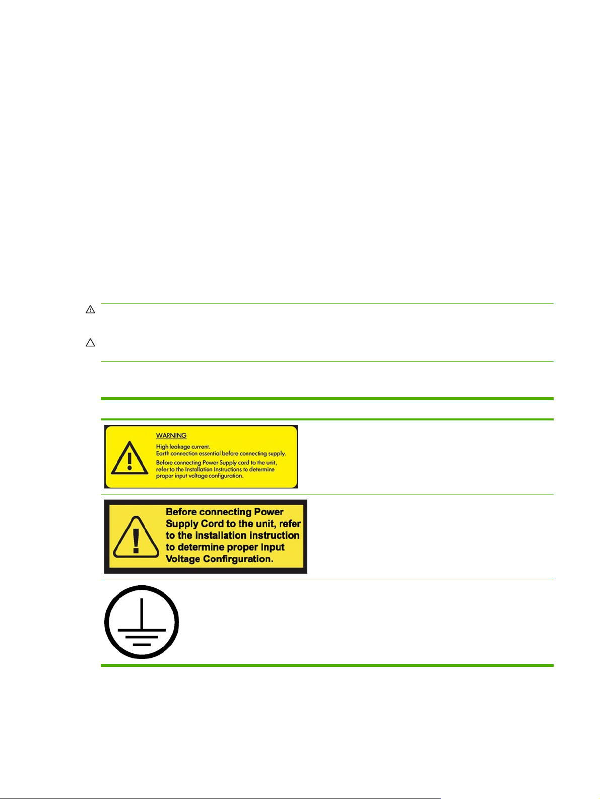
Warning labels
Label Explanation
Current leakage may exceed 3.5 mA.
The printer can be connected to power supplies at different
voltages.
Identifies the Protective Earth (PE) terminal. It is located inside
the electrical control cabinet.
ENWW General safety guidelines 3
Page 8
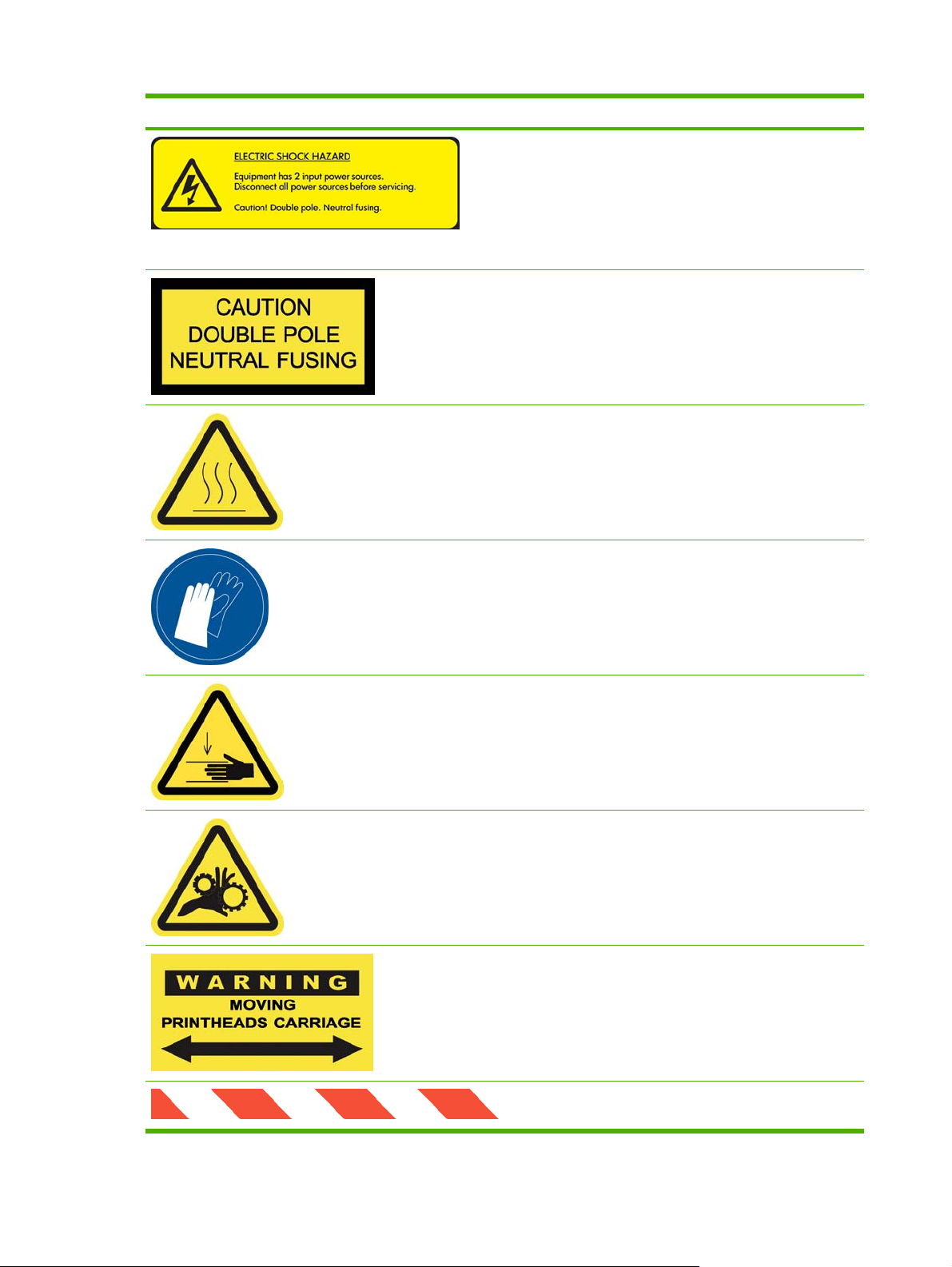
Label Explanation
Electric shock hazard. The printer has two mains supplies.
There are no operator-serviceable parts inside the printer. In
case of operation of the fuse, parts of the printer that remain
energized may represent a hazard during servicing. Refer
servicing to qualified service personnel. Turn off the printer
using both Branch Circuit Breakers located in the building's
Power Distribution Unit (PDU) before servicing. See
installation instructions before connecting to the supply.
Danger of electric shock. In case of operation of the fuse, parts
of the printer that remain energized may represent a hazard
during servicing. Therefore, ensure that the printer is
completely turned off before servicing.
Risk of burns. Do not touch the internal enclosures of the
printer's drying and curing modules.
You are recommended to wear gloves when handling ink
cartridges, printhead cleaning cartridges and the printhead
cleaning container.
When substrate has been loaded, the carriage descends into
its normal position, and could crush your hand or anything else
left underneath it.
Danger that your hands may become trapped between
gearwheels
When the printer is printing, the printhead carriage travels back
and forth across the substrate.
Beware of this moving part.
4 Chapter 1 Safety precautions ENWW
Page 9
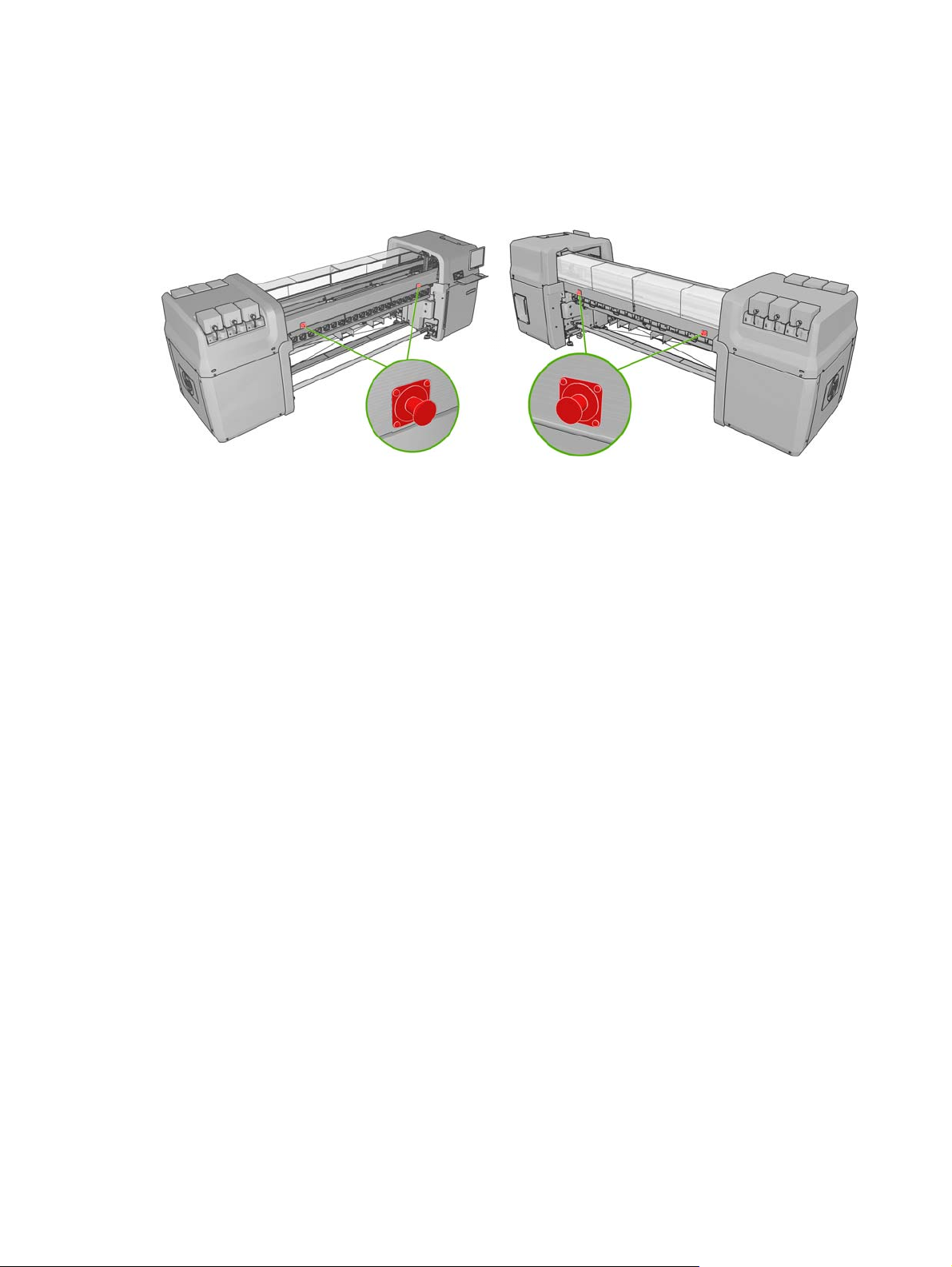
Emergency stop buttons
There are four emergency stop buttons distributed around the printer. If an emergency occurs, simply
push one of the emergency stop buttons to stop all printing processes. A system error message is
displayed on the front panel, and the fans turn at maximum speed. Ensure that all emergency stop
buttons are released before restarting the printer.
ENWW General safety guidelines 5
Page 10

2 Introduction
Installation guide overview
This installation guide provides you with step by step procedures for the installation process. This guide
is organized in chronological order and should be followed from beginning to end.
Manpower required
Installation of your HP Designjet L65500 & HP Scitex LX600/LX800 requires the following manpower:
HP Installation Specialist
●
Customer
●
Certified electrician
●
Moving specialist
●
Tools required for installation
TIP: Without a heavy-duty electric screwdriver, it could take up to two hours just to disassemble the
crate.
Installation of your HP Designjet L65500 HP Scitex LX600/LX800 requires the following tools:
Step ladder
●
Cutting pliers
●
Cutter
●
Heavy-duty electric screwdriver with two batteries
●
Phillips screwdrivers
●
T8, T10, T15, T20, T25 and T30 torx screwdrivers
●
Long torx extension pins that have a diameter of approximately 2–3 mm and are more than 15 cm
●
in length to be able to access all screws
Two Flathead screwdrivers (two sizes)
●
Socket wrench, extension and 17 mm socket
●
7 mm, 15 mm and two 30 mm open-end wrenches
●
6 Chapter 2 Introduction ENWW
Page 11

Inbox content
NOTE: The shipment items should be verified during installation.
NOTE: Ink cartridges do not come with the printer and should have been ordered by the customer
prior to installation. Make sure that the ink cartridges are available.
The shipment should include the following items:
The HP Printer
●
Documentation CD including the Legal Information , the Maintenance and Troubleshooting Guide
●
and the User's Guide
Maintenance and troubleshooting guide
●
Operating System Recovery CD
●
Pneumatic gun
●
L65500 only: 1 substrate roll
●
2 spindles (the front spindle is mounted on the printer with ties, the rear spindle is attached to the
●
pallet)
1 empty substrate core
●
L65500 only:
●
HP 786 Yellow/Magenta Designjet Printhead
◦
HP 786 Cyan/Black Designjet Printhead
◦
HP 786 Lt Magenta/ Lt Cyan Designjet Printhead
◦
LX600/LX800 only:
●
HP 786 Yellow/Magenta Scitex Printhead
◦
HP 786 Cyan/Black Scitex Printhead
◦
HP 786 Lt Magenta/ Lt Cyan Scitex Printhead
◦
LX800 only: Ink Collector Kit
●
8 collector plates (in one box)
◦
2 Diverters
◦
LX800 only: Dual Roll Kit
●
2 spindles with differential
◦
Edge Holders
◦
Allen Keys 4,6
◦
1 HP Internal Print Server computer (includes keyboard, mouse and power cord)
●
1 LAN switch (includes power cord)
●
ENWW Inbox content 7
Page 12

1 Flat screen monitor (includes power cord)
●
Ethernet cables (computer to LAN switch)
●
Keyboard Tray
●
Sliding Door Handle
●
Covers (with screws)
●
Product name label
●
Fuse and cable kit
●
6 fuses, 1 extra fuse
◦
Set of power jumpers includes 200V, 240/230V, 220V, 127V/120V and 115V/100V/110V
◦
Two electrical cabinet keys
●
Printer Cleaning Kit
●
Maintenance Kit
●
2 aerosol filters
◦
1 printhead cleaner roll
◦
Purge kit
●
7 syringes and needles (extra syringe/needle set is included)
◦
6 purge bags
◦
1 purger quick connector (already installed)
◦
4 air purgers (extra air purger is included)
◦
Protective gloves and cloth
◦
12 intermediate tanks and labels
●
NOTE: The Russian printer configuration includes two 2 MB memory cards.
8 Chapter 2 Introduction ENWW
Page 13
3 Receive the shipment
Unload the crate
Manpower Tools Time
2 persons Forklift, skates 15 minutes
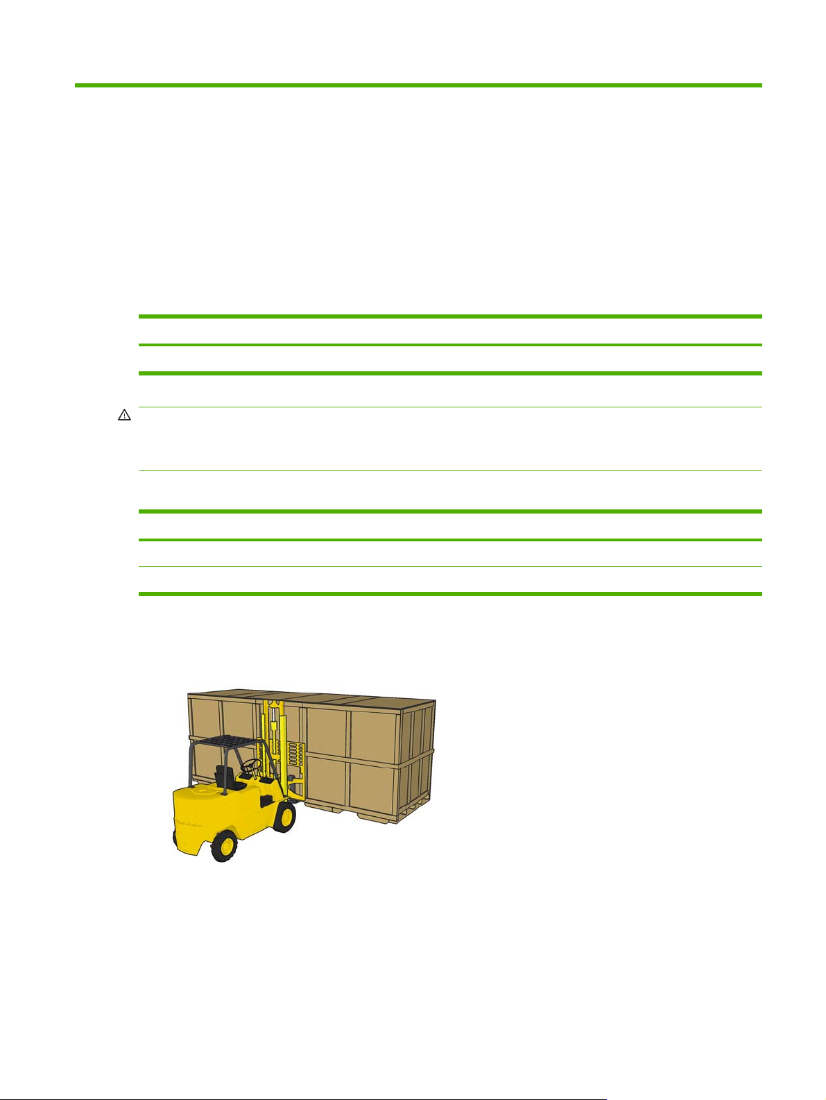
WARNING! The crate must be lifted with a forklift from the front side of the crate. The front side of
the crate will be marked Front. This is important because of the weight distribution inside the crate.
WARNING! Do not stand on top of the crate.
Shown below are the recommended specifications of the forklift that should be used to move the crate.
Weight Fork Length Distance between forks
Forklift for L65500/LX600 2721 kg (5999 lb) 2 m (78.74 in) 800 mm (31.5 in)
Forklift for LX800 3500 kg (7716 lb) 2 m (78.74 in) 800 mm (31.5 in)
1. To move the crate with a forklift, insert the forks in the designated slots on the crate. Always lift the
crate from the front and center.
ENWW Unload the crate 9
Page 14
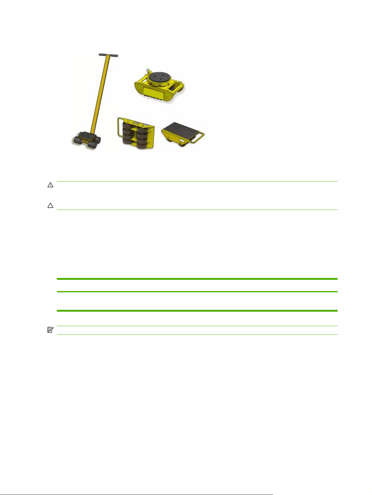
2. You can also use skates to maneuver the crate around tight corners or to move the crate laterally.
Move the printer over ramps
WARNING! Do not exceed the maximum incline if you must move the printer up or down a ramp.
Failure to respect the maximum incline could damage the printer.
CAUTION: Slopes steeper than 5% may cause serious damage to the printer.
Once the crate packaging has been removed from the printer, the maximum incline of a ramp used to
move the printer is 5%.
If you must move the printer over a ramp that exceeds the maximum incline (5%), do not remove the
printer from the pallet. The pallet will help prevent damage to the printer.
Remove the crate packaging
Manpower Tools Time
2 persons M17 socket wrench, Phillips screwdriver,
NOTE: Approximately 16 bolts and 100 Phillips screws secure the crate.
In some cases, it may be necessary to leave the printer inside the crate packaging to go up ramps or
make second story deliveries. Plan accordingly.
1. Beginning with the top, left corners, remove the Phillips screws securing the top panels and remove
them.
pliers, ladder
40 minutes
10 Chapter 3 Receive the shipment ENWW
Page 15
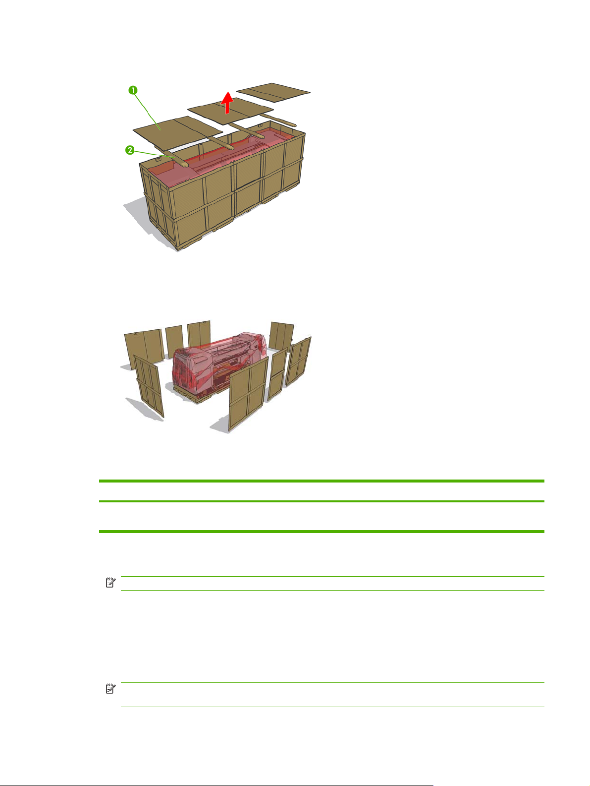
2. Remove the four support beams. Be careful that the support beams do not fall into the crate.
3. Use a Phillips screwdriver to remove the remaining screws that secure the side panels.
4. Carefully remove the panels and open the plastic bag surrounding the printer and free it from the
printer.
Remove the printer from the pallet
Manpower Tools Time
1 person Two M30 sockets, M17 socket wrench,
cutter, forklift
1. Remove the 8 Phillips screws that secure the items box and remove it.
NOTE: The starter kit weighs 60 kg. Two people are needed to lift it.
2. Remove the PC box and the disassembled covers.
3. LX800 only: Remove the Ink Collector Ink.
4. Use the 17 mm socket wrench to remove the spindle.
5. Lift the spindle away from the pallet.
NOTE: If you must lift the printer with a crane or perform difficult maneuvers, use tape to prevent
the door from opening accidentally.
ENWW Remove the printer from the pallet 11
10 minutes
Page 16
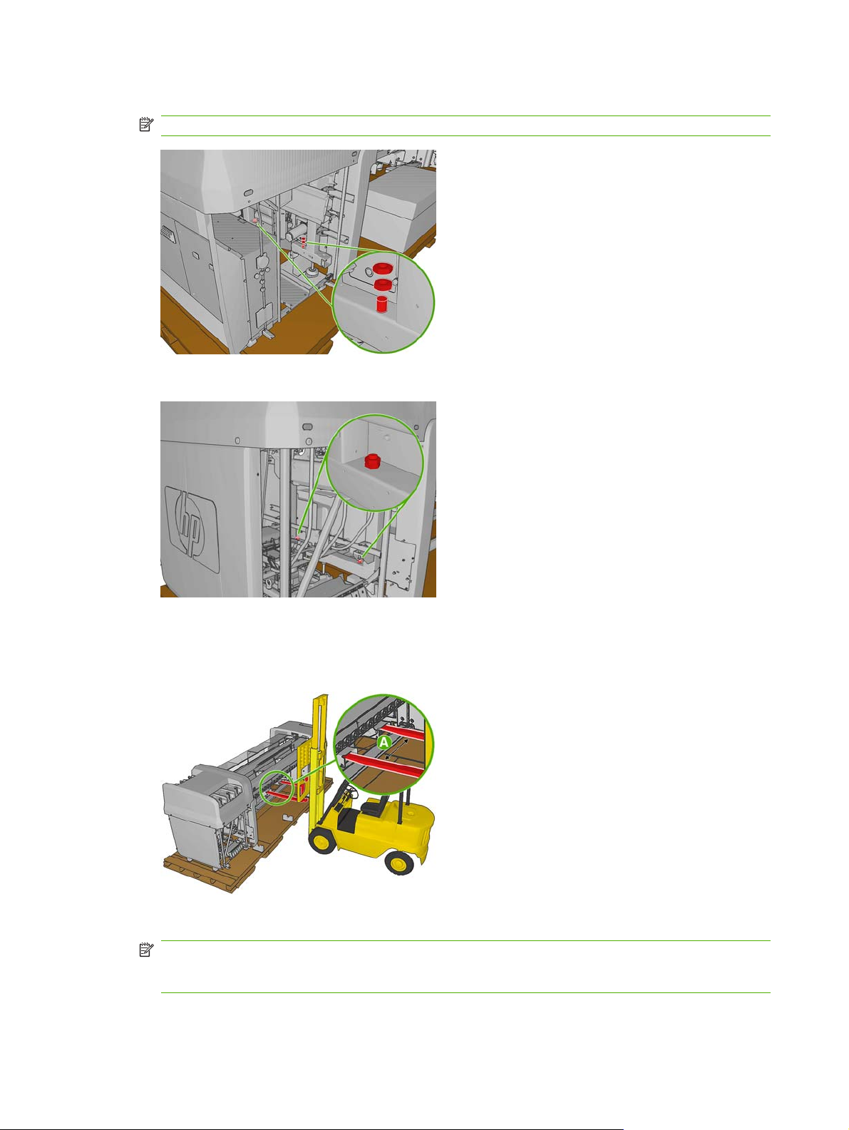
6. Remove the two 30 mm nuts attaching the left side of the printer to the pallet.
NOTE: Use a second M30 wrench to hold the second 30 mm nut in place.
7. Remove the two 30 mm nuts attaching the right side of the printer to the pallet.
8. Make sure that the feet are up and the sliding door is secured with the tape used for transportation.
9. Locate the forklift guides underneath the printer and make sure that the forks on the forklift are
spaced 80 cm apart (A).
10. Carefully lift the printer, move it away from the pallet and set it on the floor.
NOTE: The printer weighs more on the right side than the left side. Make sure that it does not tilt
toward the right hand side when you lift the printer. Make sure you lift the printer high enough so
the screws that attach the printer to the pallet do not touch the printer.
12 Chapter 3 Receive the shipment ENWW
Page 17
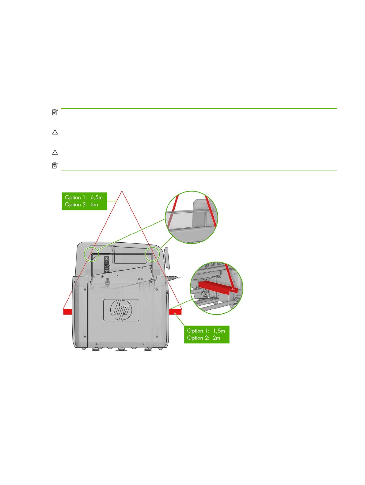
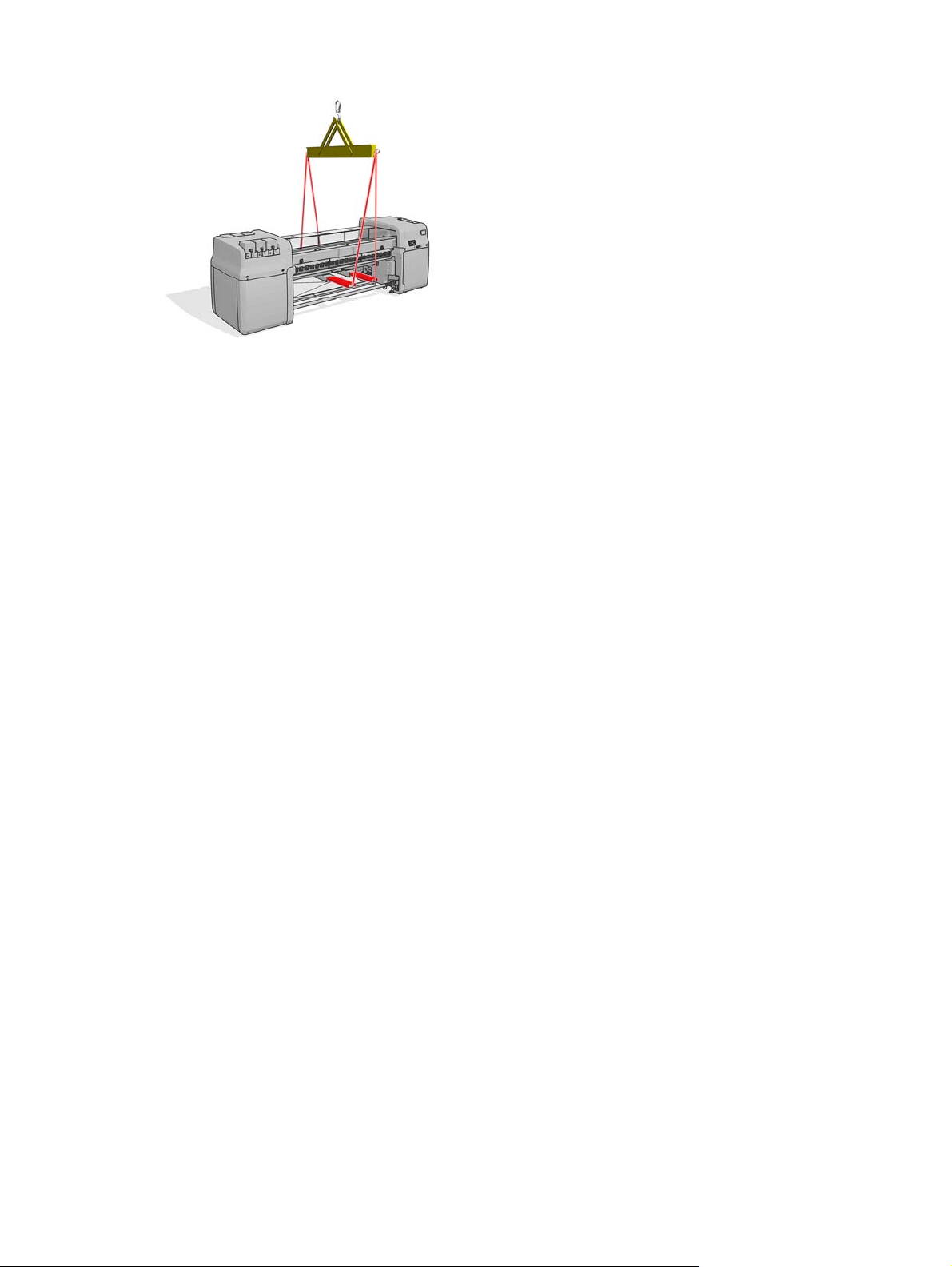
Lift the printer to a second floor using a crane
At this point, normally you would push the printer to the final location. However, if you need to make a
second floor installation, a crane will be needed to lift the printer. The same guides used to lift the printer
with a forklift should be used to lift the printer with a crane. To do so, lifting bars must be inserted into
the forklift guides. The lifting cables can either be attached to a spreader beam or directly to the crane.
In some cases, the printer can be lifted by the crane without removing the crate. If the unloading area
for the crate has enough space to disassemble the crate safely, this situation is ideal.
NOTE: The lifting bars, spreader beam and any other crane attachment must be supplied by the
customer. For the exact specifications of the crane attachments, see the Site Preparation Guide.
WARNING! When lifting the printer with a crane, extra caution should be taken to ensure that the
cables do not apply pressure to the center covers or carriage beam.
CAUTION: The printer weight is not evenly distributed, and it may tilt to the right side.
NOTE: The printer will bend as you lift it.
The following graphic illustrates how to lift the printer using lifting bars.
If you use a spreader beam to lift the printer, make sure that the spreader beam and lifting bars are wide
enough so the lifting cables do not touch the center covers or carriage beam. The following graphic
illustrates how to lift the printer with a spreader beam.
ENWW Lift the printer to a second floor using a crane 13
Page 18
14 Chapter 3 Receive the shipment ENWW
Page 19
4 Set up the printer in the final position
How to push the printer
Manpower Time
2 persons Varies
NOTE: Do not remove the ISM or electrical cabinet straps until the printer is in the final position.
When you set the printer on the floor, the printer wheels allow you to easily roll the printer.
Only push the printer from the outside corners of the top covers on either side of the printer.
Choose the final position
Your HP Designjet L65500 printer requires enough space to perform the following tasks:
Print
●
Use the HP Internal Print Server
●
Replace a substrate roll
●
Service the printer or replace printer components
●
Ensure the printer is well ventilated
●
The printer has the following dimensions:
ENWW How to push the printer 15
Page 20
Printer Length Width Height
HP Designjet L65500 5 m (16 ft, 5 inches) 1.6 m (5 ft, 3 inches) 1.8 m (5 ft, 11 inches)
HP Designjet LX600 5 m (16 ft, 5 inches 1.6 m (5 ft, 3 inches) 1.6 m (5 ft, 3 inches)
HP Designjet LX800 5.7 m (18 ft, 11 inches) 1.6 m (5 feet, 3 inches) 1.6 m (5 feet, 3 inches)
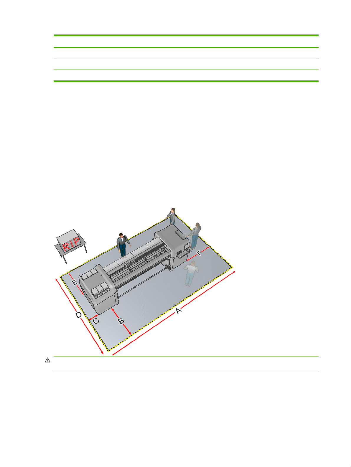
The following table and illustration shows the minimum space required for the printer.
Measurement
A L65500/LX600: 7m (23ft)
LX800: 8m (26ft 3 in)
B 1.5 m (5ft)
C 0.6 m (2 ft) minimum
D 4 m (13 ft, 2 in)
E 1.5 m (5 ft)
F 1.5 m (5 ft)
WARNING! The zone surrounding the HP Designjet L65500 printer should be considered a restricted
access area and signaled accordingly. Only trained personnel should be operating within this area.
16 Chapter 4 Set up the printer in the final position ENWW
Page 21
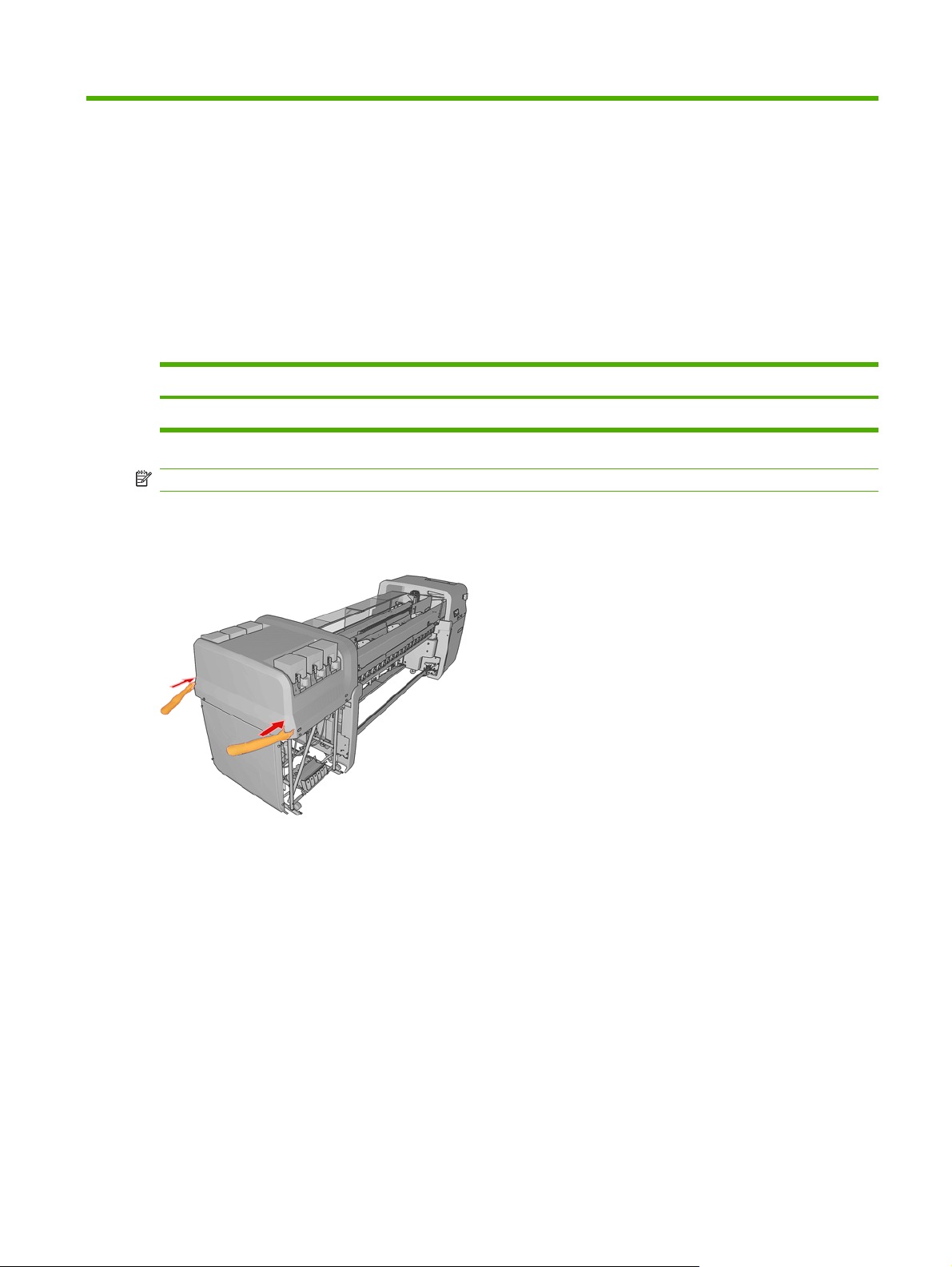
Remove additional packaging
Manpower Tools Time
1 person Cutting Pliers, Allen keys, T20 and T25
screwdrivers
15 minutes
1. From the back, remove the electrical cabinet straps and foams from the printer.
2. Remove the straps from the sliding doors.
NOTE: The keys to the electrical cabinet are located on top of the cabinet.
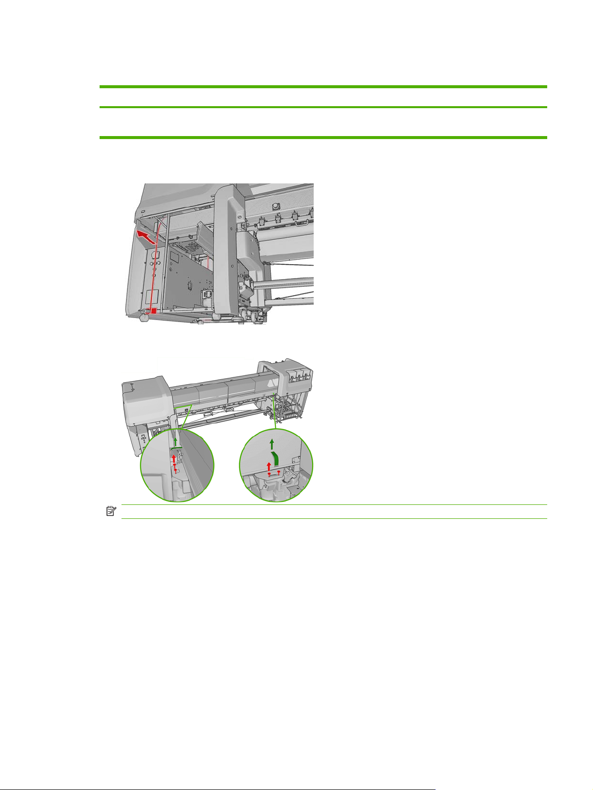
ENWW Remove additional packaging 17
Page 22
3. Remove the eight T20 screws attaching the scan path assembly to the frame. Use a screwdriver
extension for easier screw access.
WARNING! Failure to remove the screws attaching the scan path assembly to the frame could
seriously damage the printer.
NOTE: The screws located at the back, are less accessible and may require a longer screwdriver.
4. Remove tape from the window and open the carriage access door, remove the T30 screw securing
the carriage.
18 Chapter 4 Set up the printer in the final position ENWW
Page 23
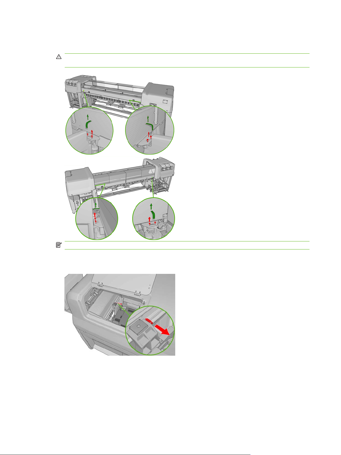
5. Remove the tie and 2 foam pieces that secure the service station.
6. Remove the four foam pieces that secure the top cover.
7. Remove the two T20 screws securing the printhead cleaning assembly.
8. Remove the substrate pressure handle straps (pinches).
9. Remove the plastic ties securing the diverter.
ENWW Remove additional packaging 19
Page 24
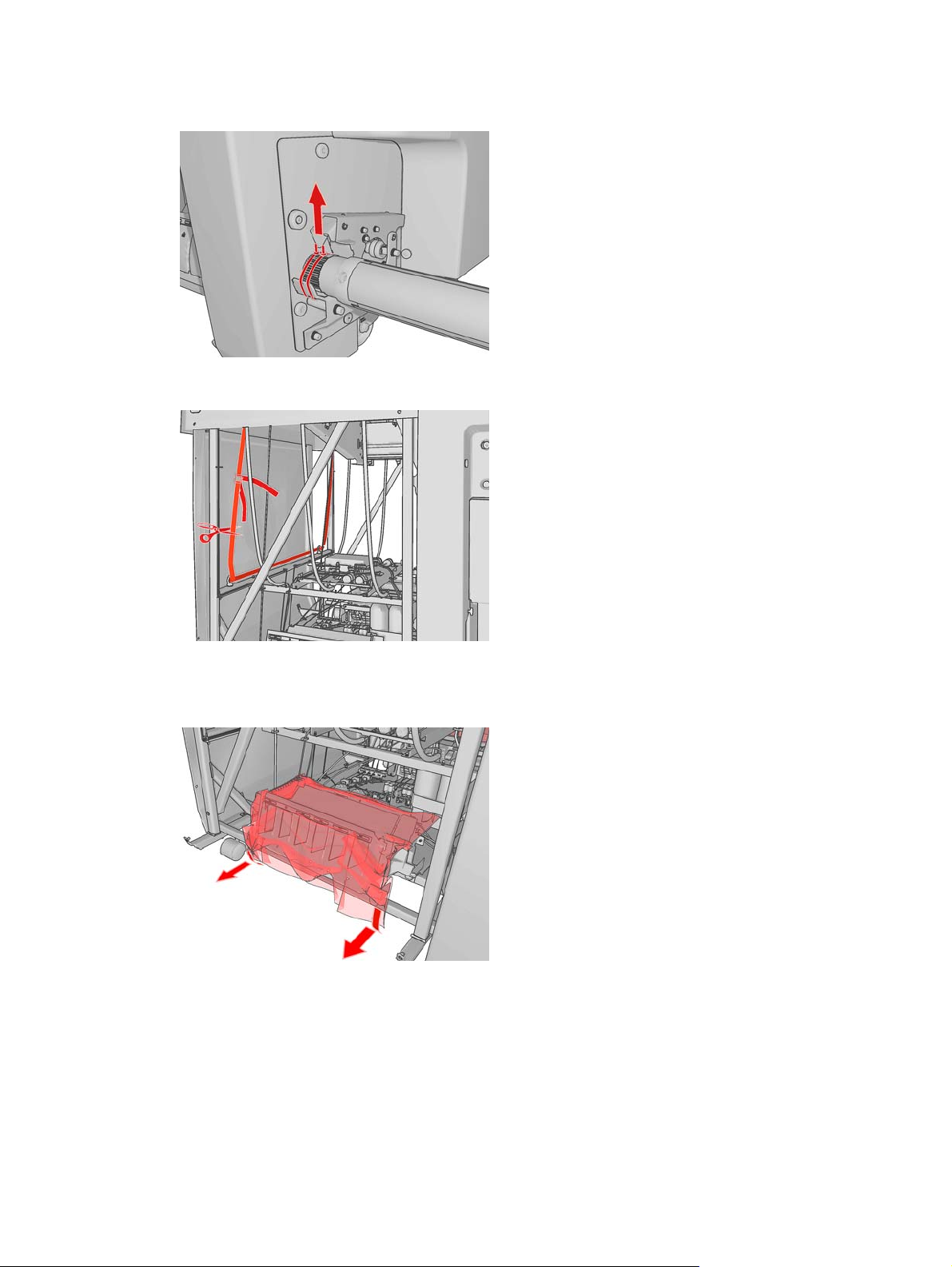
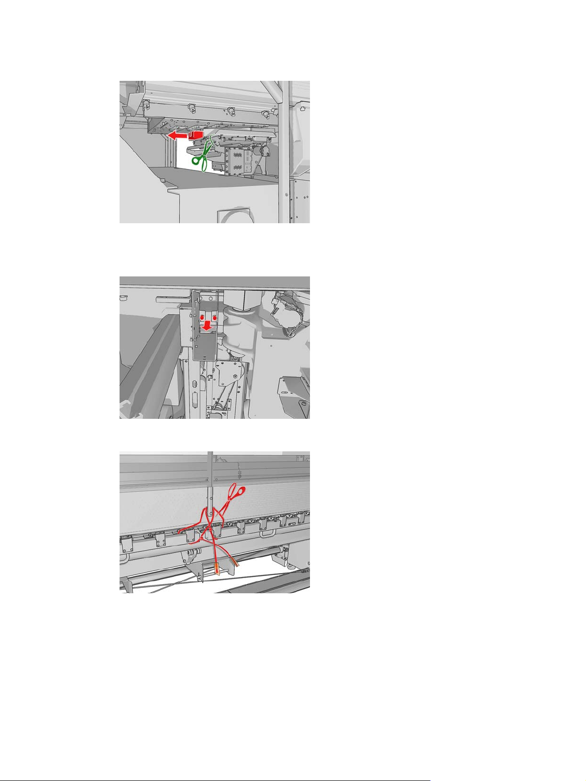
10. Remove the plastic tie securing the spindle and the tape covering the air valve.
11. Remove the ink system compartment strap from the printer.
12. Remove the plastic coverings from the ink cartridge connectors.
13. Remove the intermediate tank plastic bags, foams and straps.
14. Remove the plastic ties securing the tri-phase and single-phase power cables.
15. Remove any other plastic ties that you can see inside the printer.
20 Chapter 4 Set up the printer in the final position ENWW
Page 25
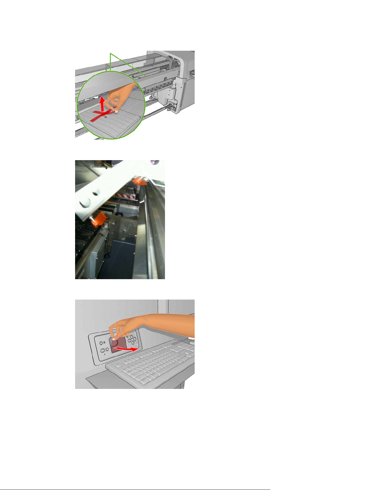
16. Remove the tape covering the OMAS window on the print platen.
17. Remove the tapes covering the temperature sensors.
18. Remove the plastic covering from the carriage access door , front panel and central cover.
19. Remove tape from the Curing Plate.
20. Remove foam pieces from the left and right.
21. Remove foam pieces from the rear beam structure.
ENWW Remove additional packaging 21
Page 26
22. Remove 4 plastic ties from the left side cover.
23. Remove plastic ties from the top covers.
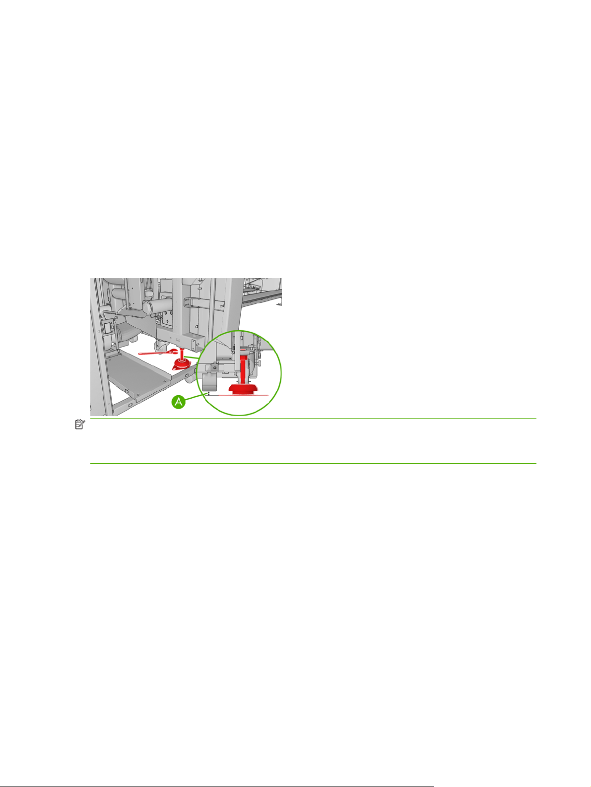
Lower the feet
1. Use a 30 mm wrench to unlock the nut at the top of the foot.
2. Rotate the nut manually down the bolt. Leave about 0.8 inches (2 cm) of clearance at the bottom
between nut and foot.
3. Use a 15 mm wrench to rotate the foot downwards. Use the flat faces at the bottom of the bolt to
fit the wrench.
4. Lower the foot as far as the bolt allows.
5. Once the wheels are 15 mm (A) off the ground, tighten the 30 mm locking nut against the printer
structure
NOTE: The right side of the printer is heavier than the left side. Therefore, the feet on the right side
will be more difficult to lower.
NOTE: The position of the feet must be parallel with the spindle.
22 Chapter 4 Set up the printer in the final position ENWW
Page 27

5 Connect the power cables
Requirements
An electrician is required for the setup and configuration and building of the electrical system used to
power the printer and also for printer installation. Make sure that your electrician is appropriately certified
according to local regulations and supplied with all the information regarding the electrical configuration.
Configure the building's electrical system used to power the printer to meet the printer's requirements
and the Electrical Code requirements of the local jurisdiction of the country where the equipment is
installed. A qualified electrician is required.
Your printer requires the following electrical components to be supplied and installed by the customer,
according to the Electrical Code requirements of the local jurisdiction of the country where the equipment
is installed.
Remember that you are required to follow the local laws, regulations, and standards that pertain to the
electrical installation of your printer.
Tri-phase AC Power Cord
The cable must meet the requirements of the printer and should be in accordance with the Electrical
Code requirements of the local jurisdiction of the country where the equipment is installed.
Printer's tri-phase line specifications High-voltage systems Low-voltage systems
Input voltage (line to line) 3 x 380–414 V~ (-10% +6%) 3 x 200–220 V~ (±10%)
Input frequency 50 Hz 60 Hz (1)
Power Consumption 15 KW 15 KW
Maximum Load Current 30 A 50 A
1
Japan may have input frequencies of 50 Hz or 60 Hz
Power Cord Specification
Configuration 4 Wires, L1/L2/L3/PE
Minimum cross-sectional area
The power cord must enter into the printer through the AC power gland, and securely fit into it, in order
to avoid any slip even when the cord suffers a pull force of 100N.
High-voltage systems High-voltage systems
AWG6, 16mm
2
AWG6
ENWW Requirements 23
Page 28

Tri-phase Power Cord attachment
1. The Tri-phase AC power cord must be attached to the back of the Main Switch.
2. Back of the Main Switch is shown below:
This Main Switch is made by two blocks of identical size, each one having three contacts. The left
block is dedicated to tri-phase lines, so the three contacts are used. The block on the right side is
dedicated to single-phase lines, so only two contacts form the total of three are used.
24 Chapter 5 Connect the power cables ENWW
Page 29

The AC power cords (tri-phase and single-phase) have to be screwed to the bottom terminals of the
switch. Add adequate ferrules on power cord cable terminations. In total there are 6 terminals to attach
wires, and only 5 of them are to be used. They are labeled (from left to right): L1, L2, L3, (blank), L0 and
N. Each wire must be securely attached to the terminals of the power switch.
Label on Switch Wire Power Cord
L1 Phase Tri-phase
L2 Phase Tri-phase
L3 Phase Tri-phase
Blank — —
L0 Phase Single-phase
N Neutral Single-phase
ENWW Tri-phase AC Power Cord 25
Page 30

Protective Earth conductors (grounding)
The printer must be connected to a good quality, dedicated ground line in order to avoid electrical risk.
Please note your obligation to comply with the Electrical Code requirements of the local jurisdiction of
the country where the equipment is installed.
Protective Earth attachment
The ground wires coming from the tri-phase power cord and from the single-phase power cord
▲
must be fitted with round terminals suitable for attaching into M6 pillar terminal. Reliable screw
attachment must be used. They are close to Protective Earth (PE) terminal marking which are
located in the Cabinet on the right as shown on the picture below.
Protective Earth (PE) terminal markings:
26 Chapter 5 Connect the power cables ENWW
Page 31

6 Configure the electrical system
Install the fuses and power jumper
Manpower Time
1 person 5 minutes
NOTE: The electrical system inside the printer must be configured by the service engineer during
installation.
CAUTION: If there are any doubts regarding the proper installation of the fuse or power jumper,
consult the certified electrician that knows the voltage of the electrical installation.
TIP: The electrical cabinet key is located in a plastic bag secured to the top of the electrical cabinet.
Open the sliding door to find it.
1. Power fuse holder blocks
2. Vacuum transformer
NOTE: The Vacuum transformer is located in the purging kit box.
ENWW Install the fuses and power jumper 27
Page 32

Install the fuses
1. Use the key to access the electrical cabinet.
2. Open the two fuse holder blocks.
3. Insert the six fuses (three per fuse block) into the fuse holder with the piston facing you.
Printer Sites with high voltage supply (200–
HP Designjet L65500/LX600 20 A 32 A
HP Designjet LX800 25 A 40 A
1
Japan may have input frequencies of 50 Hz or 60 Hz
4. Close the fuse holder until you feel and hear a “click.” The red square above the fuse holder should
change color once all fuse holders have been inserted.
Install the power jumpers
290V)
Sites with low voltage supply (100–
120)
1. There are five power jumpers supplied. Select the appropriate power jumper according to the
single-phase power at the installation site. Inserting the wrong power jumper will cause the vacuum
pump to work incorrectly.
2. Insert the correct power jumper into the connector, located close to the transformer.
28 Chapter 6 Configure the electrical system ENWW
Page 33

Choose delta or star (Y) configuration
Manpower Tools Time
1 person T10 and M15 screwdriver, M7 wrench 5 minutes
There are two Delta/Star terminal blocks located on the printer that must be configured. Use the following
table to make the configuration, and follow the procedures below to access the two terminal blocks.
CAUTION: Both Delta/Star terminal blocks must use the same configuration.
Delta configuration
1
Use the delta configuration for tri-phase power supply voltages from 200–220 V (between phases).
2
Use the star configuration for tri-phase power supply voltages from 380–415 V (between phases).
Heating Module Configuration
1. Remove the six T10 screws securing the middle cover of the heating module and remove it.
TIP: The heating module cover you must remove is marked with orange tape.
1
Star configuration
2
ENWW Choose delta or star (Y) configuration 29
Page 34

2. To make the delta or star configuration, use the metal strips and configure them according to the
table. Use an M7 socket wrench to secure them.
Curing Module Configuration
1. Remove all the T10 screws securing the right cover of the curing module and remove the cover.
TIP: The heating module cover you must remove is marked with orange tape.
2. There is a strap that does not allow you to remove the terminal block. Remove this strap, taking
care that you replace it after making the configuration.
3. Remove the T15 screw securing the terminal block and pull it out for easy access.
4. To make the delta or star configuration, use the metal strips and configure them according to the
table. Use an M7 socket wrench to secure them.
30 Chapter 6 Configure the electrical system ENWW
Page 35

WARNING! The curing module terminal block must use the same configuration as the drying
module.
Check resistances
Check the resistance at the output of the static relay, as shown below, through the hole protecting the
static relay.
Also check the resistance between A2-B2, A2-C2, B2-C2 (marked on the static relay and on the heating
and curing cables: 1, 2, 3).
The acceptable values are as follows.
Triangle configuration (low input tri-phase, 200-220 V between phases): resistance should be
●
16 Ω (minimum: 15 Ω , maximum: 17 Ω).
Star configuration (high input tri-phase, 380-415 V between phases): resistance should be 32 Ω
●
(minimum: 30 Ω, maximum: 34 Ω).
Check connections
Check that the following items are correctly connected.
The main interconnect
●
The left remote controller board (remove the left trim)
●
The ink supply module board
●
The capping station's remote controller board
●
The printhead cleaning roll station
●
The tri-phase cables on the static relay: within the electrical cabinet, on the left, the two big black
●
relays)
The neutral or zero line of the tri-phase cables must not be connected.
ENWW Check resistances 31
Page 36

Connect mains power
Manpower Time
1 person 5 minutes
NOTE: This task must be performed by a certified electrician provided by the customer.
NOTE: Make sure to route the power cables under the electrical cabinet structure.
1. Use the key to access the electrical cabinet.
2. Connect both power cables to the AC mains using the appropriate connectors or by wiring them
directly to the PDU, according to the National Electrotechnical Code (NEC). For more information
about the HP Designjet L65500 electrical specifications, see the Site Preparation Guide.
Power on the printer
Manpower Time
1 person 5 minutes
Ground check
1. Check that the Protective Earth Conductor for the single-phase and tri-phase (green-and-yellow
2. Check that the Protective Bonding Conductor (green-and-yellow grounding cable) is well attached
grounding cable) is well attached to the back panel of electrical cabinet.
to the electrical cabinet doors.
32 Chapter 6 Configure the electrical system ENWW
Page 37

3. Check that the Protective Bonding Conductor (green-and-yellow grounding cable) is well attached
to the back panel of the electrical cabinet.
4. Check that the Protective Bonding Conductor (green-and-yellow grounding cable) is well attached
to the input single-phase filter.
ENWW Power on the printer 33
Page 38

5. Check that the Protective Bonding Conductor (green-and-yellow grounding cable) is well attached
to the printer structure.
6. Check that the Protective Bonding Conductor (green-and-yellow grounding cable) is well attached
to the drying system (at the resistor connection).
34 Chapter 6 Configure the electrical system ENWW
Page 39

7. Check that the Protective Bonding Conductor (green-and-yellow grounding cable) is well attached
to the curing system (at the resistor connection).
Turn power on
1. Make sure that the printer is ready to be turned on.
2. Turn the power switch ON.
3. Go the front panel and see if it is on. If it is not on, press and hold the Power key for a few seconds
Make sure that the emergency stop buttons are not pressed.
Make sure the ACB-1, ACB-2 and ACB-3 circuit breakers located on the electrical cabinet door are enabled (in
the UP position).
Make sure the electronics box switch is turned on.
Have you removed all the additional packaging?
Have you lowered the feet?
Is the correct power jumper installed?
Are the delta/star terminal blocks configured correctly?
Are the carriage access door and sliding door closed?
Are all tools and other objects clear from the printer?
Make sure that no people are touching the printer.
to start the printer.
ENWW Power on the printer 35
Page 40

4. Verify that all four LED lights on the rear side of the electrical cabinet are on (PH1, PH2, PH3,
Vacuum ON).
5. Wait for the printer to initialize.
NOTE: The printer will automatically start in diagnostic mode so you can purge the ink system.
When you first turn on the printer, you must set the voltage according to the country of installation.
Configure the voltage
1. From the front panel, enter the diagnostic menu and select Purge and Setup Menu > 3ph AC Volt
Setup Menu to display a list of voltages.
2. Select the correct voltage according to the country of installation and press OK.
NOTE: Select the tri-phase nominal mains voltage (line to line) according to the Electrical
Installation section of the Site Preparation checklist.
3. Press the Power enable button on the rear side of the printer. It should light up orange.
36 Chapter 6 Configure the electrical system ENWW
Page 41

7 Purge the ink system
Manpower Tools Time
1 person Syringe, Gloves, Clean cloth 60 minutes
Do the purging process one color at a time. Always double check to make sure you are inserting the
right color of ink into the purging port. Before installing the purge bags, check that the electrical
connectors are not bent or damaged.
The purge process requires at least 1.7 liters of ink per ink cartridge.
Purge the ISM tubes
NOTE: From the ink cartridge to the purging port, no air can be tolerated. From the purging port to the
printhead, the printer can tolerate a cumulative total of 20 cm of air (the length of the bubble) in the tubes
per color. Small pockets of bubbles are acceptable.
CAUTION: To avoid damaging the printer, do not force any tube or connection. Gently manipulate the
syringe during insertion and purging.
1. Install the six purge bags.
2. Begin connecting the purger quick connector. To do so, hold each end of the quick connection with
your hands.
3. Press and hold the green button on the ISM side of the quick connector.
4. If not already installed (some printers may have this part already installed), insert the purger quick
connector until both sides of the connection are perfectly aligned, and release the green button on
the ISM side of the quick connector, complete the coupling, until you hear a click.
ENWW 37
Page 42

5. Release the green button on the ISM side of the quick connector and complete the coupling. You
should hear a click.
CAUTION: Use only moderate force to make the connection. If it is difficult to make the
connection, do not continue. Instead, start the process again. Using too much force could damage
the internal fittings of the connectors.
6. Test the connection by gently pulling both connectors away from each other.
7. From the diagnostic menu on the front panel, select Purge and Setup Menu > Purge ISM.
8. Select the color you want to purge.
Ink Supply Legend
●
●
●
●
●
●
NOTE: The printer starts up the procedure, which may take a couple of minutes.
TIP: Do not press the OK button more than once.
9. Place the cartridge on a flat surface and turn it four times (rotating it through 360 degrees) as
indicated on the label, to ensure that the ink is well mixed before use.
1 = K
2 = Y
3 = C
4 = M
5 = LM
6 = LC
38 Chapter 7 Purge the ink system ENWW
Page 43

10. Insert a clean syringe into the ink cartridge and fill it with 60 cc of ink for the color selected.
11. From the front panel, press OK to open the electrovalves. You now have 200 seconds to feed the
remaining ink into the purging port before the electrovalve closes.
NOTE: The printer will beep during these 200 seconds.
12. Check that all of the electrovalves have opened (you can hear a clicking sound). If not, perform the
4.6 ISS Electrovalves diagnostic procedure described in the Service Manual. While the test is in
progress, tap vigorously on the body of the electrovalve with a tool such as a screwdriver.
13. Check that there is no air in the syringe by hitting it a few times. If there is air, hold the syringe
vertically with the needle up, so that the bubble of air rises to the top. Put a cloth around the needle,
and press gently on the piston to remove the air from the syringe.
14. Insert the syringe in the purging port (next to the ink pressure sensor) for the color selected, and
slowly push the ink until it clearly reaches the purger quick connector and the purge bags.
TIP: Make sure to insert the syringe far enough into the port. In order to insert the ink correctly,
the tip of the syringe must engage a small spring inside the port.
CAUTION: If you apply too much force to the syringe, you may damage the ink system. If there
seems to be too much resistance, stop pushing the ink with the syringe and try to identify possible
problems.
CAUTION: Never look away from the syringe. If you need to look at the purge bags or something
else in the room, set down the syringe first. The ink system components are easily broken.
ENWW 39
Page 44

Ink Supply Legend
●
●
●
●
●
●
CAUTION: Do not push the ink from the syringe if the electrovalves are not open. You will notice
too much resistance if the electrovalves are not open.
TIP: If you run out of ink in the syringe, you can refill the syringe from the ink cartridge. Keep track
of how much ink you remove from the ink cartridge, because you will be asked to report the quantity
of ink taken. Make sure the electrovalves are still open.
15. Remove the syringe from the purge port with a cloth around the needle to prevent spills.
16. Press OK on the front panel to close the electrovalves.
17. Check that the ink has arrived as far as the purging bag and purger.
18. Press OK to confirm that you have finished purging the ink tubes for the color selected.
1 = K
2 = Y
3 = C
4 = M
5 = LM
6 = LC
19. Disconnect the purge bag and connect the ink cartridge. If the ink cartridge is connected correctly,
the cartridge LED will show a constant green light.
40 Chapter 7 Purge the ink system ENWW
Page 45

20. When the ink cartridge has been installed correctly, press OK.
21. Press OK to confirm that you have installed the ink cartridge.
22. The printer checks the pressure sensors.
If the pressure is correct, press OK to continue.
If the pressure sensor value is below the limits or is negative then follow the steps in Problems with
the ink sensor value on page 42.
23. Enter the quantity of ink you extracted from the ink cartridge. If you extracted ink from the cartridge
twice and purged the ISM in two steps, enter the total sum of the ink extracted.
24. Select the next color and repeat.
ENWW 41
Page 46

25. Remove the purger quick connector.
Problems with the ink sensor value
1. There are three different cases that can cause a problem.
The pressure sensor value is below a limit, which may vary depending on the volume of the
●
supply. Probably there is an air bubble inside the cartridge connector tube column. Prepare
the syringe again. Press OK and continue with step 2.
The ink volume of the cartridge is too low to register on the pressure sensor. To ensure there
●
are no air bubbles in the tube, you are recommended to purge again. Press BACK and
continue with step 2. If you think there are no air bubbles, press OK and continue the process
of purging the ISM tubes from where you were.
42 Chapter 7 Purge the ink system ENWW
Page 47

The pressure sensor gives a negative value. If the pressure is negative, there may be an error
●
in the ink pressure PCA or in the ink pressure sensor cable. Check both by looking at the
connection of the cable to the ISS PCA and at the pressure sensor PCA. Press OK to cancel
the purge process.
2. If the pressure is positive, probably there is an air bubble inside the cartridge connector tube
column. Prepare the syringe again, then press OK.
3. Insert the same syringe into the ink cartridge and fill it with 20 cc of ink for the color selected.
4. Check that there is no air in the syringe by hitting it a few times. If there is air, hold the syringe
vertically with the needle up, so that the bubble of air rises to the top. Put a cloth around the needle,
and press gently on the piston to remove the air from the syringe.
ENWW 43
Page 48

5. Insert the syringe in the purging port (next to the ink pressure sensor) for the color selected, and
slowly push the ink until it clearly reaches the quick connector purger and the purge bags.
TIP: Make sure to insert the syringe far enough into the port. In order to insert the ink correctly,
the tip of the syringe must engage a small spring inside the port.
CAUTION: If you apply too much force to the syringe, you may damage the ink system. If there
seems to be too much resistance, stop pushing the ink with the syringe and try to identify possible
problems.
CAUTION: Never look away from the syringe. If you need to look at the purge bags or something
else in the room, set down the syringe first. The ink system components are easily broken.
TIP: You will notice more resistance than before because the electrovalves are not open.
TIP: If you run out of ink in the syringe, you can refill the syringe from the ink cartridge. Keep track
of how much ink you remove from the ink cartridge, because you will be asked to report the quantity
of ink taken.
6. Remove the syringe from the purge port with a cloth around the needle to prevent spills.
7. Press OK to confirm that you have finished purging the ink tubes for the color selected.
8. Disconnect the purge bag and connect the ink cartridge. If the ink cartridge is connected properly,
the ink cartridge LED shows a continuous green.
9. Continue with step
20 in the process of purging the ISM tubes. If the problem is not solved after
trying this twice, perform the 4.5 ISS Ink Pressure Sensors diagnostic procedure found in the
Service Manual.
44 Chapter 7 Purge the ink system ENWW
Page 49

Fill the intermediate ink tanks
1. From the front panel, select Purge and Setup Menu > Fill intermediate tanks.
2. Install all the intermediate ink tanks, apply the labels (match them to the labels on the printer) and
confirm that they are installed from the front panel.
The printer unfolds the intermediate ink tanks. This process takes approximately 25 minutes.
NOTE: During this time, you can install the printhead cleaner roll, aerosol filters, HP Internal Print
Server and switch. See
the computer, monitor, LAN switch, tray, keyboard and mouse on page 53.
3. When the printer finished unfolding the intermediate ink tanks, press OK to continue.
Install the printhead cleaning roll and aerosol filters on page 50 and Install
The printer fills the intermediate ink tanks. This takes a few minutes.
4. When the process is finished, check that the ink cartridge LED is green and press any key to
continue.
ENWW 45
Page 50

Purge the tubes from the ISM to the printheads
1. Install the three air purgers into the three empty printhead ink ports.
2. From the front panel, enter the diagnostic menu and select Purge and Setup Menu > Purge
Printer Tubes.
3. Begin connecting the quick connector. To do so, hold each end of the quick connection with your
hands.
WARNING! Always handle the quick connector by the protective tubing to avoid damaging the
internal fittings.
4. Press and hold the green button on the ISM side of the quick connector.
46 Chapter 7 Purge the ink system ENWW
Page 51

5. Partially insert the quick connector until both sides of the connection are perfectly aligned.
6. Release the green button on the ISM side of the quick connector and complete the coupling. You
should hear a "click".
CAUTION: Use only moderate force to make the connection. If it is difficult to make the
connection, do not continue. Instead, start the process again. Using too much force could damage
the internal fittings of the connectors or result in an incorrect color matching of the ink tubes.
7. Test the connection by gently pulling both connectors away from each other.
8. Make sure the quick connector is placed in the holding panel.
9. Press OK to start the purge.
At this point, the printer sends ink to the carriage. This process takes approximately 5 minutes.
10. The front panel prompts you to confirm that ink has reached the air purgers. Look at the air purgers
and confirm that each color arrived to the air purger.
11. If ink did not reach one of the air purgers, use a syringe to complete the operation. For instructions,
Use a syringe to purge the tubes from the ISM to the printheads on page 49.
see
ENWW 47
Page 52

12. Wear gloves and use a cloth to remove the air purgers, as some ink may spill. When you have
finished removing the air purgers, close the carriage cover and access window. Press OK to finish.
13. At this point, check to make sure that the rear ink leakage sensor is correctly placed at the bottom
of the tray (it should be touching the tray).
14. From the front panel, enter the diagnostic menu and select Purge and Setup Menu > Force
Normal Boot .
15. The printer sets the boot configuration.
48 Chapter 7 Purge the ink system ENWW
Page 53

16. The printer displays OK when the configuration is set. Press any key to finish.
17. Switch the ACB-1 breaker switch ON and OFF again to restart the printer in normal boot mode.
NOTE: The printer performs a complete system check during start up. If a failure is detected
during start up, follow the troubleshooting instructions in the Service Manual.
18. When the printer finishes initializing, select the preferred language in the front panel.
Use a syringe to purge the tubes from the ISM to the printheads
If the ink does not arrive to any of the air purgers, you must use a syringe to complete the purging
operation. This procedure is only necessary if the ink did not arrive to one or more of the air purgers.
1. Fill the printhead pockets with paper or cloth to prevent spilled ink or dirt from dirtying the printhead
interconnect contacts.
2. Use a cloth to remove the air purger to which ink did not arrive.
3. Insert an empty syringe into the ink port where you removed the air purger. Make sure the syringe
plunger is pushed all the way into the syringe before you insert it into the ink port.
4. Enter the service menu and select Purge and Setup Menu > Purge Printer Tubes to perform the
purge again.
5. The air will pass from the tubes into the syringe until the ink reaches the syringe. The syringe
plunger will move by itself.
NOTE: If the syringe plunger does not move at all, pull it out no more than 1 mm. Otherwise,
never manually pull the syringe plunger out.
6. When the purge operation is finished, put a cloth around the needle and remove the syringe quickly.
NOTE: Wait until the purge operation is completely finished before you remove the syringe.
7. Continue from step 6 of the previous procedure.
ENWW 49
Page 54

8 Prepare the printer
Install the printhead cleaning roll and aerosol filters
Install the printhead cleaning ro ll
NOTE: You should install the printhead cleaning roll during the purging process to save time. You can
install the printhead cleaning roll when the printer is off or in diagnostic mode. Otherwise, when the
printer starts in normal boot mode, it will detect that the printhead cleaner roll is missing and you can
install it at that time.
1. In order to replace the printhead cleaning roll, open the door on the front right of the printer.
2. Grip the handle and pull the whole printhead cleaning roll assembly out through the door.
3. Slide both rolls off their axles and dispose of the roll with the used cleaning material according to
the instructions provided with the new roll. Keep the empty core to use as a takeup core.
4. Slide the new roll onto the upper axle. It clicks into place.
5. Pull the black knob on the upper left and move the pinch system aside.
50 Chapter 8 Prepare the printer ENWW
Page 55

6. Pass the leading edge of the roll over the upper rollers, and thread the cleaning material through
the rollers on the left.
7. There is a strip of polyester film on the leading edge of the cleaning material. Insert it into the hole
in the takeup core, which takes hold of it.
8. Slide the takeup core onto the lower axle. It clicks into place.
NOTE: If the cleaner roll has not been properly installed, you may see a message about clearing
a printhead cleaning roll jam. Pull the whole assembly out, wind a little of the roll forward, then slide
it back in again. The printer will check the roll again
9. Restore the pinch system by moving the black knob back into place. If you feel resistance because
the cleaning roll is too tight, turn the roll slightly counter-clockwise.
10. Grip the handle and push the whole printhead cleaning roll assembly back into the printer.
11. Close the door.
ENWW Install the printhead cleaning roll and aerosol filters 51
Page 56

Install the aerosol filters
1. Open the printhead access door in the side of the printer, and lift the carriage cover.
2. The aerosol filter containers are on the near and the far sides of the printheads.
3. Lift up the right-hand side of the filter container; it pivots on the left.
4. Pull the old filter out of the bottom of its container and dispose of it according to the instructions
provided with the new filter.
5. Unpack the new filters and ensure that the blue tabs at each end of each filter are at right angles
to the filter.
6. Insert the new filter into the container.
52 Chapter 8 Prepare the printer ENWW
Page 57

7. Ensure that the blue tabs on the filters are correctly engaged with the hooks on the containers,
otherwise the containers may not close completely.
8. Lower the container into position.
9. Lower the carriage cover and close the door. Press the OK key on the front panel.
10. When you finish the purging process and are ready to start the printer, select Check cleaner
roll from the Ink System menu
in normal printer mode.
Install the computer, monitor, LAN switch, tray, keyboard and mouse
Manpower Tools Time
1 person T20, T30 Phillips screwdriver 30 minutes
NOTE: Perform this task while you fill the intermediate ink tanks.
1. Install the keyboard platform with four T30 screws (two of which you will find already screwed into
the printer), and route the keyboard and mouse cables through the hole in the top cover.
NOTE: Use the longer of the two power cables (computer and monitor) to power the monitor.
WARNING! Do not route the keyboard, mouse or monitor cables over the front panel cable.
ENWW Install the computer, monitor, LAN switch, tray, keyboard and mouse 53
Page 58

2. Open the sliding door and check that all cables are routed above the sliding door support.
Otherwise, over the course of time the movement of the door will damage the cables.
Cables wrongly positioned: hanging over the sliding door support
Cables correctly positioned: supported above the sliding door support
3. Use a T20 screwdriver to remove the monitor holder on the printer.
4. Remove the Phillips screws that secure the monitor arm and remove it. Keep the screws.
5. Attach the holder to the monitor using the 4 Phillips screws from the monitor arm.
6. Attach the holder to the printer with the four T20 screws.
TIP: It is better to connect the power cable to the monitor before connecting it to the printer.
7. Connect the monitor, keyboard and mouse to the computer.
54 Chapter 8 Prepare the printer ENWW
Page 59

8. Plug the power cords of the computer, monitor and LAN switch into the outlets provided on the side
of the electrical cabinet facing the computer.
WARNING! The outlets are for the computer, monitor and switch only. Never plug any other
equipment into the outlets.
9. Place the HP Internal Print Server computer in the electrical compartment and secure it with the
two straps.
10. Put the switch inside the electrical compartment.
11. Route the customer LAN cable and connect it to the switch.
NOTE: The LAN cable, on the customer network side, must be connected to a hub/switch port
configured as autosense. Otherwise, there will be no communication between the HP switch
provided with the printer and the rest of the customer’s network. The HP Procurve 1400-8G switch
that is included with the printer supports one low-level communication protocol: autosense. If the
connector to which the switch is connected is set to any other protocol (such as half-duplex), no
communication can occur.
12. Connect the HP Internal Print Server computer to the switch using the cable included in the
shipment.
13. Connect the printer to the switch using the available cable.
14. Plug the power cord of the switch into the power strip.
NOTE: For Russian installations, you must also install the two 2 MB memory cards.
Create a shared folder on the HP Internal Print Server computer
A shared folder must be created on the HP Internal Print Server computer for the RIP to be able to send
jobs to the HP Internal Print Server and view the contents of the shared folder.
1. Log in to the HP Internal Print Server computer using the administrative user account that is already
set up on the computer.
HP Designjet L65500: User name hp65500, no password.
●
HP Designjet LX800/LX600: User name scitexlx, no password.
●
2. Create a folder called OutJobs.
ENWW Create a shared folder on the HP Internal Print Server computer 55
Page 60

3. Open the folder properties for the new OutJobs folder and navigate to the Sharing tab.
4. Click on Advanced Sharing to set the sharing properties.
5. Make sure that Share this folder is selected.
56 Chapter 8 Prepare the printer ENWW
Page 61

6. Set the other settings to your requirements, then click on Permissions.
7. Add any groups or users required, and set the permissions as required by the customer.
8. Navigate to Control Panel > Network and Internet > Network and Sharing Center on Windows
Vista, and make sure that File Sharing is turned on.
ENWW Create a shared folder on the HP Internal Print Server computer 57
Page 62

Configure the printer’s IP address
NOTE: If you cannot establish a connection between the printer and Internal Print Server, make sure
that no proxy is configured. See
1. To open the Internal Print Server, double-click the Internal Print Server icon on the desktop.
2. Set the printer IP address in the Internal Print Server, under Tools > Preferences.
Configure the proxy on page 75.
3. Configure HP Proactive Support and make sure the customer accepts all disclaimers, under
Tools -> Proactive support
58 Chapter 8 Prepare the printer ENWW
Page 63

9 Prepare for printing
Install the printheads
Manpower Time
1 person 5 minutes
After the initial power up of the printer in normal boot mode, the printer recognizes that the printheads
are not installed. Use the following procedure to install the printheads and also follow the instructions
on the front panel.
1.
At the front panel, select the Ink System icon
2. When requested by the front panel, open the printhead access door in the side of the printer.
3. Lift the carriage cover.
and then Replace printheads.
ENWW Install the printheads 59
Page 64

4. Check that the new printhead is of the correct colors.
NOTE: Each printhead has a unique shape and cannot be inserted into the wrong slot.
5. Remove its packaging and protective cap.
TIP: Keep the protective cap and do not lose it. It may be necessary to store the printheads in
the original protective caps for future servicing.
6. Shake the printhead according to the instructions on the packaging.
7. Put the new printhead into its correct place in the printer, and lower its handle.
CAUTION: Insert the printhead slowly and vertically, straight down. It may be damaged if you
insert it too fast, or at an angle, or if you rotate it as you insert it.
8. When you have inserted all the printheads, close the printhead latches.
9. Close the carriage cover.
10. Close the printhead access door.
60 Chapter 9 Prepare for printing ENWW
Page 65

If a printhead fails to work correctly, try the following recommendations.
1. Use the procedures in the Service Manual, described under “Large ink area missing or substantial
horizontal banding”.
2. Request a hard clean of the printhead, and illuminate the space between the printheads and the
printhead cleaning roll while the printhead is being cleaned.
Check that the primer is working correctly (first step of the hard cleaning): big dots should form
●
under the printhead.
Check that static spitting is functioning correctly (second step, seen as 'heavy rain').
●
3. Inspect the ink deposited on the printhead cleaning roll during printhead cleaning. You should see
a large area saturated with ink, followed by a pattern of smaller areas of ink. If the large saturated
area is missing, the primer is not working.
If the primer is not working:
1. Go to the front panel and start the process to replace the printhead in question.
2. After lifting the printhead cover, you will see two 'O' rings that seal the joints between the printhead
cover and the printhead. Apply a little oil, grease or water to the 'O' rings to improve their
performance.
3. Check the primer's electrical connections.
4. Close the printhead cover, the carriage cover and the printhead access door.
5. Request a hard clean of the printhead.
ENWW Install the printheads 61
Page 66

Callme@HP Setup Process
During installation process, specific information must be introduced into the IPS preferences to correctly
route the Remote Support Calls to the Support Agent (HP or Authorized Service Provider approved to
provide this Remote Support Service).
1. Go to the IPS menu “Tools”, then press “Preferences” and look for the tab “Callme@HP”.
2. Enter in information into all 6 fields
The first four fields are related to customer data. They can be generic and are intended to be
automatically loaded as default data into the Remote Support Application.
a. Printer Serial Number: Check that the serial number is correctly entered into the text field.
b. Agent e-mail: This parameter is VERY important as it establishes the call routing to the
appropriate support organization. If the configuration of this field is not correct any support
calls made will not reach the intended recipient.
If the Reseller partner is going to provide the support for the unit AND has been approved
●
for using this tool and has the account setup and permissions setup, enter in this field
the E-mail of the reseller engineer supporting this printer, using the reseller's domain
used for creating the account.
If the reseller is not entitled to use the “Callme@hp” remote troubleshooting tool, then
●
leave the default value: printcare@hp.com
3. Launch the “callme@HP” application under the “tools” menu option and verify the information
entered loads correctly into the template.
Important: The application will ask for software to be installed, select yes to all the requirements.
62 Chapter 9 Prepare for printing ENWW
Page 67

If no window is displayed, go to the Site Preparation document under the section where the network
requirements are described, and check that all the requirements for network connectivity have been
met.
4. Submit a Testing Call including the following text in the comment box: “Customer Name Installation
Call. Remote Support Configuration Check”.
Antivirus Registration
Antivirus software is pre-installed with the PC equipment. Antivirus license will be valid for 5 years.
License renewal will be the Customer's responsibility and it's a requirement for the use of the
Callme@HP tool.
Note that the installation and registration process may vary after this document has been generated.
Always keep updated with the installation notes.
Web Cam Installation
Unpack the web cam from the package and connect it to the PC of the printer. Wait until the operating
system displays “HW ready to use”.
Go to Windows Start>Print Care Webcam> and check the webcam function.
In case of any install issues,re install the drivers from the CD included with the Web cam.
Load a substrate
For information regarding loading and handling substrates, see the User's Guide.
Connect the air supply
1. Locate the airgun and adaptor that was included with the printer shipment.
ENWW Antivirus Registration 63
Page 68

2. The customer should have the correct air supply with the correct connection. Use the adaptor to
connect the airgun to the customer air supply.
Configure the RIP
A Raster Image Processor (RIP) should be run on a separate computer, In this section we describe how
to configure the RIP correctly for use with the printer.
L65500 only: RIP software is not provided with the printer, and cannot be installed on the same
●
computer as the HP Internal Print Server.
LX800/LX600 only: The RIP software is sold with the printer:
●
HP Scitex Onyx RIP Software CQ756A
◦
HP Scitex Caldera RIP Software CQ755A
◦
The customer's RIP for use with the HP Designjet L65500 Printer
The customer's RIP must be configured correctly to work with the HP Designjet L65500 Printer. Because
HP cannot support the customer's RIP, any troubleshooting must be done using the documentation and
service that accompany the RIP. However, generally three tasks must be done:
1. Configure the IP address or network name of the HP Designjet L65500 Printer.
2. Configure the RIP to recognize the shared output folder with the HP Internal Print Server.
3. Make any additional configurations required by the RIP.
64 Chapter 9 Prepare for printing ENWW
Page 69

HP Scitex Onyx RIP
The HP Scitex Onyx RIP is sold with the HP Scitex LX800/LX600 Printer. After the RIP software has
been installed and the printer has been added to the RIP, use the following procedure to configure the
RIP.
1. Following the installation process of the RIP, the screen 'Configure Printer Port' should
automatically be displayed. If not launch the RIP-Queue and select 'Configure the Printer'. The
following screen is displayed, select 'Print to HP Internal Printer Server' and click on the
'Configure' button.
2. The following screen is displayed. Enter or browse to the Internal Print Server shared folder.
3. Enter the IP address of the printer to enable the dynamic media list retrieval. Click Test to check
that it responds.
4. Click OK to confirm the printer configuration.
ENWW Configure the RIP 65
Page 70

HP Scitex Caldera RIP
The HP Scitex Caldera RIP is sold with the HP Scitex LX800/LX600 Printer. After the RIP software has
been installed and the printer has been added to the RIP, use the following procedure to configure the
RIP.
1. Go to the 'Special menu' in the RIP and click on 'Server Admin'.
2. Click on 'Configure' and select the 'Connection' tab, the following screen is displayed. Enter the
IP address of the printer (not the IP address of the IPS).
Install the covers
Manpower Tools Time
1 person T30 screwdriver 5 minutes
66 Chapter 9 Prepare for printing ENWW
Page 71

NOTE: The covers are wrapped in plastic, and the screws are inside the packaging. It is recommended
to install the covers last, in case of any issue that may require you to remove the covers. It is
recommended to wear gloves when removing the covers.
1. On the left side, replace the six T30 screws that secure each cover. The position of the screws is
the same on the rear cover as it is on the front cover.
2. On the right side, replace the four T30 screws that secure the rear cover.
3. On the right side, replace the four T30 screws that secure the sliding door, starting at the top.
ENWW Install the covers 67
Page 72

Print the HP test images
Test images are available with which you can check the print quality achieved once the printer has been
fully installed. From HP's Web site (
software & drivers, type the name of the printer, select Drivers, and download the pre-ripped images.
NOTE: L65500 only: The test prints are also available in the Internal Print Server computer if your
printer has a serial number beginning with SG95 or greater.
The following three images are available, each designed to test the print quality in a different way.
Filename: Petra Filename: Notatravel Filename: Fish
http://www.hp.com/), select Support & drivers, check Download
The main purpose of these pre-ripped files is to be able to check the print quality achieved by using files
that do not need to be ripped, and have been set up for the substrate supplied with the printer. This will
avoid any print-quality issues due to the RIP application or to a mismatch of substrate/RIP selections.
If any issues are found, the error can come only from the printer’s installation and setup. It is important
when selecting the print that the correct file is selected for the type of substrate loaded. There is a choice
of two, and the correct selection will depend on which type of substrate is loaded in the printer:
L65500 Printers only with serial numbers lower than SG96M1F002 are delivered with HP
●
Photorealistic substrate. The pre-ripped images are located in C:\Users\L65500\Documents\HP
IPS\Test Plot\ripped Photorealistic.
L65500 Printers only with serial numbers SG96M1F002 and greater are delivered with HP
●
Permanent Gloss Adhesive Vinyl. The pre-ripped images are located in C:\Users\L65500
\Documents\HP IPS\Test Plot\ripped SAV Gloss.
LX800 and LX600 Printers are delivered without substrate rolls. The pre-ripped images are
●
located in the following locations:
C:\Users\scitexlx\Documents\HP IPS\Test Plot\Ripped Photorealistic
◦
C:\Users\scitexlx\Documents\HP IPS\Test Plot\Ripped SAV Gloss
◦
Make sure before printing the files that the printer is ready to print at its best.
1. Load the roll of substrate provided with the printer.
2. Align the printheads (see the Maintenance and Troubleshooting Guide).
3. Check the printhead alignment.
68 Chapter 9 Prepare for printing ENWW
Page 73

4. Fine-tune the substrate advance with the print mode or modes that you intend to use. We
recommend using the following internal test plot from the Internal Print Server computer: C:\Users
\'the printer name'\Documents\HP IPS\Test Plot\ , plot name: SubstrateTestPlot. Set the correct
print mode and substrate, and print the test plot. See the Maintenance and Troubleshooting
Guide.
5. Perform Dynamic Color Calibration, mainly when using the HP Photorealistic substrate. A specific
user's guide for this calibration is available from
http://www.hp.com/.
6. Print the three ripped files provided, using the Internal Print Server. Nest them to print all on the
same row. We recommend using four to eight passes.
When you inspect the prints, you should observe no defects from a viewing distance of one meter if
printing with six or eight passes, or from three meters if printing with four or five passes.
NOTE: The option of five passes is not available with the HP Photorealistic substrate.
ENWW Print the HP test images 69
Page 74

A Prepare the HP Internal Print Server
(Japan and Russia only)
Manpower Time
1 person 45 minutes
The following procedure must only be performed in Japan and Russia.
1. Power up the HP Internal Print Server computer.
2. Choose the language for Windows Vista.
TIP: Remember that the HP Internal Print Server software will automatically be installed in the
language you choose for Windows Vista.
3. Create two users. Create an administrative user called “HPAdmin” and create a non-administrative
user called “HPL65500.”
TIP: HP recommends that you password protect all users.
4. Create a computer name that makes sense. HP recommends a name like HPL65500–n, where n
is any number.
Update the rate index
1. Right click Computer and select properties.
2. Click on Windows Experience Index.
70 Appendix A Prepare the HP Internal Print Server (Japan and Russia only) ENWW
Page 75

3. Click on Update my score.
Change the power settings
1. Select Control Panel > Hardware and Sound > Power Options.
ENWW 71
Page 76

2. Select High performance and click on Change plan settings.
3. In the Put the computer to sleep field, select Never.
72 Appendix A Prepare the HP Internal Print Server (Japan and Russia only) ENWW
Page 77

Set a blank screen saver
1. Right click anywhere on the desktop and select Screen Saver.
TIP: The Screen Saver Settings window is also available under Control Panel > System and
Maintenance > Performance Information and Tools.
2. In the Screen Saver drop down menu, select Blank.
Configure the hard disk
1. Select Start > Computer > (Right click) Manage > Device Manager >Disk drives > HDD
>Properties > Policies (tab).
2. Check the following:
Optimize for performance
●
Enable write caching on the disk
●
Enable advanced performance
●
ENWW 73
Page 78

Enable scheduled defragmentation
1. Select Start > Computer > (Right click) Manage > Disk Management >(Right click) C: >
Properties > Tools.
74 Appendix A Prepare the HP Internal Print Server (Japan and Russia only) ENWW
Page 79

2. Check Run on a schedule.
Configure visual effects
1. Select Control Panel > System and Maintenance > System > Advanced system settings (left
column) > Advanced >Performance > Visual Effects > Custom.
2. Only the following should be checked:
Enable Desktop composition
●
Enable transparent glas s
●
Smooth edges of screen fonts
●
Use visual styles on windows and buttons
●
Configure the proxy
1. Log in with the HPL65500 account.
ENWW 75
Page 80

2. In Internet Explorer, select Tools > Internet options > Connections > LAN settings.
3. Check By-pass proxy server for local addresses.
Install the HP Internal Print Serv er
TIP: If necessary, the HP Internal Print Sever executable file can be found on the web at
http://www.hp.com under the Support & Drivers tab.
1. Find the setup.exe icon on the desktop, double click on the icon and follow the on-screen
instructions.
76 Appendix A Prepare the HP Internal Print Server (Japan and Russia only) ENWW
Page 81

2. From the Internal Print Server, navigate to Tools > Preferences and set the printer IP address in
the Internal Print Server.
3. From the Internal Print Server, navigate to Tools > Pr oactive support. Configure the HP Proactive
Support and make sure the customer accepts all disclaimers.
4. Configure Call@HP
5. Install the Antivirus Eset32 software.
ENWW 77
Page 82

B Manually configure the printer’s IP
address
If the customer does not have DHCP, the printer and/or Internal Print Server computer is not able to
automatically retrieve an IP address. In this case, you must manually configure the IP address. Use the
following procedure to manually configure the IP address for the printer.
1.
Select the setup menu icon
2. Select Connectivity.
3. Select Gigabit Ethernet.
4. Select View Information.
.
78 Appendix B Manually configure the printer’s IP address ENWW
Page 83

5. Select TCP/IP.
6. Select IPV4 Settings.
7. Select Config Method.
8. Select Manual to change the configuration so the printer uses the manual settings.
9. From the IPV4 Settings menu, select Manual Settings.
ENWW 79
Page 84

10. Select IP Address to edit the settings.
11. Edit the IP address settings and press OK when you are finished.
80 Appendix B Manually configure the printer’s IP address ENWW
Page 85

C Change the Windows Vista language
1. Navigate to the Control Panel on the Internal Print Server and select Clock, Language, and
Region.
ENWW 81
Page 86

2. Select the appropriate entry from the format list.
82 Appendix C Change the Windows Vista language ENWW
 Loading...