

Page 1

5Service Parts & Diagrams
• Printer Support................................................................................................. 446
• Left Covers .......................................................................................................447
• Right Covers.................................................................................................... 448
• User Interface .................................................................................................. 449
• Electronics........................................................................................................450
• Electrical Cabinet .............................................................................................. 451
• Electrical Cabinet Doors.....................................................................................453
• Front Substrate Path (1 of 2) ................................................................................454
• Front Substrate Path (2 of 2)................................................................................455
• Rear Substrate Path (1 of 2) ................................................................................456
• Rear Substrate Path (1 of 2) ................................................................................456
• Dual Roll Assembly & Ink Collector & Diverter .......................................................458
• Roll to Floor Assembly (LX800)............................................................................459
• Ink System (1 of 3)............................................................................................ 460
• Ink System (2 of 3) ............................................................................................ 461
• Ink System (3 of 3) ............................................................................................462
• Scan Axis (1 of 3) .............................................................................................463
• Scan Axis (2 of 3)............................................................................................ 464
• Scan Axis (3 of 3).............................................................................................465
• Carriage Assembly........................................................................................... 466
• Printhead Cleaning Assembly .............................................................................467
• Heating Module................................................................................................468
• Curing Module .................................................................................................469
• Internal Print Server PC ...................................................................................... 470
• Cables............................................................................................................. 471
• Additional Parts ................................................................................................473
Service Parts & Diagrams
Service Parts & Diagrams 445
Page 2
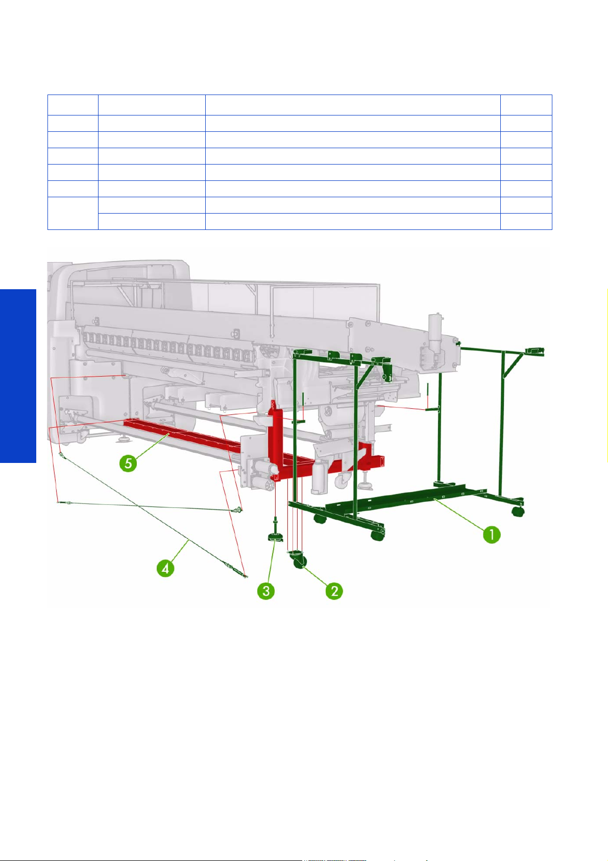
Printer Support
Ref HP Part Number Part Description Page
1 Q6702-60542 Electrical Cabinet Support 507
2 Q6702-60421 Stand Wheel Assembly 506
3 Q6702-60420 Stand Rubber Foot Assembly 506
4 Q6702-60423 Stands Cross Tensioners (L65500/LX600) 507
4 Q6703-67009 Stands Cross Tensioners (LX800)
5
Q6702-60422 Stands and Cross Brace Assembly (left and right)(L65500/LX600)
Q6703-67008 Stands and Cross Brace Assembly (left and right) (LX800)
Service Parts & Diagrams
446 Service Parts & Diagrams
Page 3
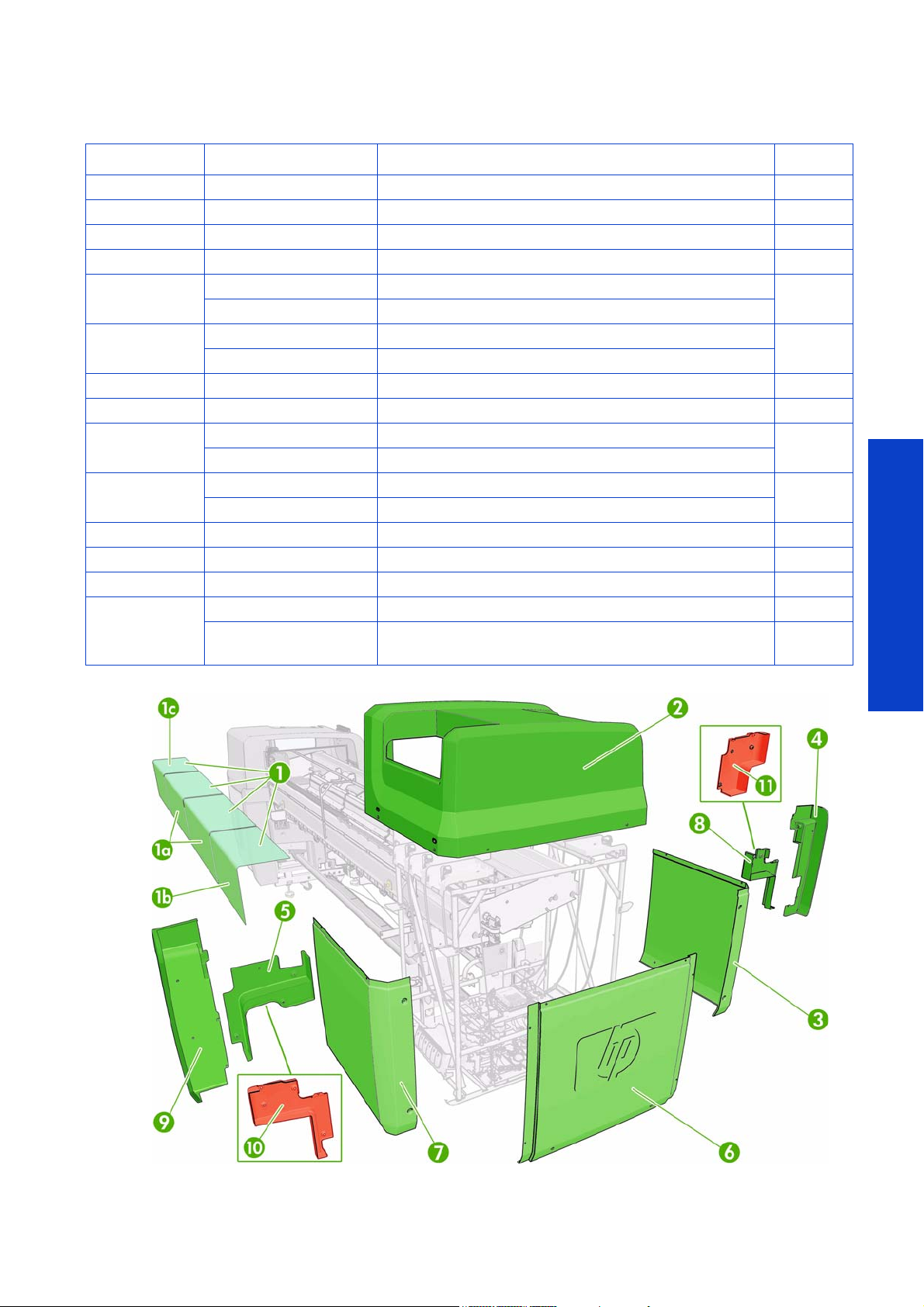
Left Covers
Ref HP Part Number Part Description Page
1 Q6702-60522 Window Covers (L65500/LX600)(4 off) 491
1a Q6703-67032 Extended Long Center Cover (LX800)(1 off)
1b Q6703-67054 Left Side Window Cover (1 off)
1c Q6703-67055 Right Side Window Cover (1 off)
2
3
4 Q6702-60523 Left side front Arc cover 488
5,8 Q6702-60527 Left Side trims cover set (L65500/LX600)a 488
6
7
9 Q6702-60524 Left side rear Arc cover 488
10 Q6703-67034 Left Side Rear Trim cover (LX800) 489
11 Q6703-67033 Left Side Front Trim cover (LX800) 488
Not shown
Q6702-60518 Left side top cover (L65500)
Q6703-67053 Left side top cover (LX/600LX800)
Q6702-60519 Left side Front Panel (L65500)
Q6703-67029 Left side Front Panel (LX600/LX800)
Q6702-60520 Left Side Lateral Panel (L65500)
Q6703-67030 Left Side Lateral Panel (LX600/LX800)
Q6702-60521 Left Side Rear Panel (L65500)
Q6703-67031 Left Side Rear Panel (LX600/LX800)
Q6702-67008 Top Left cover Metal Supports (L -shape 4 off: six screws)
Q6702-67009
484
483
483
483
Cosmetic Cover Screws (8 off) that secure the side covers,
and metal supports
Service Parts & Diagrams
Service Parts & Diagrams 447
Page 4
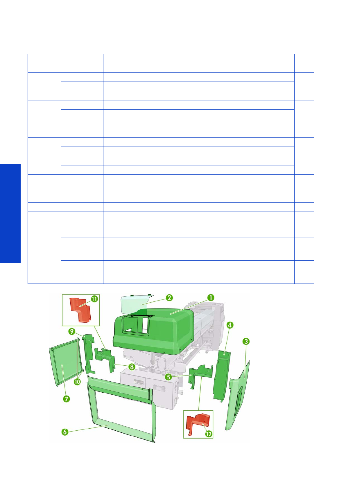
Right Covers
The two Officeability
kits have two common
parts:
The PH cleaning roller
access restriction and
top right transparent
door with locker
Ref HP Part
Number
1
2 Q6702-60515 Right side cover window assy (may include lock) 487
3
4 Q6702-60526 Right side rear Arc cover 489
5,8 Q6702-60528 Right side trims cover set (L65500/LX600) 490
6
7
9 Q6702-60525 Right side front Arc cover 489
10 Q6702-67017 Front right sliding door wheel. 485
11 Q6703-67035 Right side Front trim cover (LX800) 490
12 Q6703-67036 Right side Rear trim cover (LX800) 490
Not shown
Q6702-60513 Right side top cover assy (L65500)
Q6703-67025 Right side top cover assy (LX600/LX800)
Q6702-60516 Right side cover rear panel assy (L65500)
Q6703-67027 Right side cover rear panel assy (LX600/LX800)
Q6702-60517 Right side cover lateral panel (L65500)
Q6703-67028 Right side cover lateral panel (LX600/LX800)
Q6702-60514 Right cover slide door assy (door wheels and support) (L65500)
Q6703-67026 Right cover slide door cover (LX600/LX800)
Q6702-67007 L-shape metal supports (4 off) for Top right Cover, includes screws
Q6702-67009
Q6702-67031
Service Parts & Diagrams
Q6703-67112
Part Description Page
Cosmetic Cover Screws (8 off) that secure the side covers, and metal
supports
Officeabilty Upgrade kit (includes: front central transparent panel, PH
cleaning roller access restriction and top right transparent door with locker
(will be available from Summer-Fa ll 2010 ) (L X60 0 &L 655 00 )
Officeabilty Upgrade kit (includes: front central transparent panel, PH
cleaning roller access restriction and top right transparent door with locker
(will be available from Summer-Fall 2010) (LX800)
486
485
485
485
492
492
448 Service Parts & Diagrams
Page 5
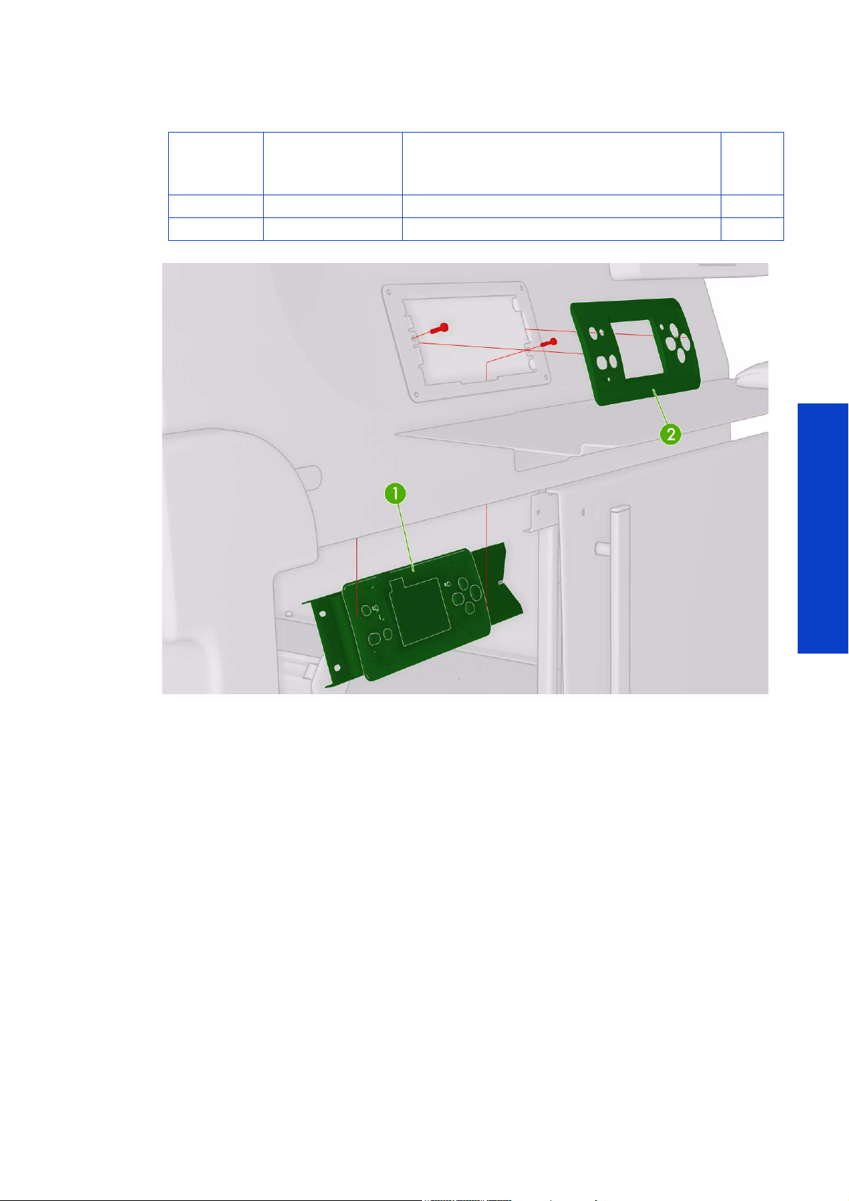
User Interface
Reference
on
Figure
1 Q6702-60387 Front Panel 504
2 Q6702-60388 Front Panel Bezel 505
HP Part Number Part Description Page
Service Parts & Diagrams
Service Parts & Diagrams 449
Page 6
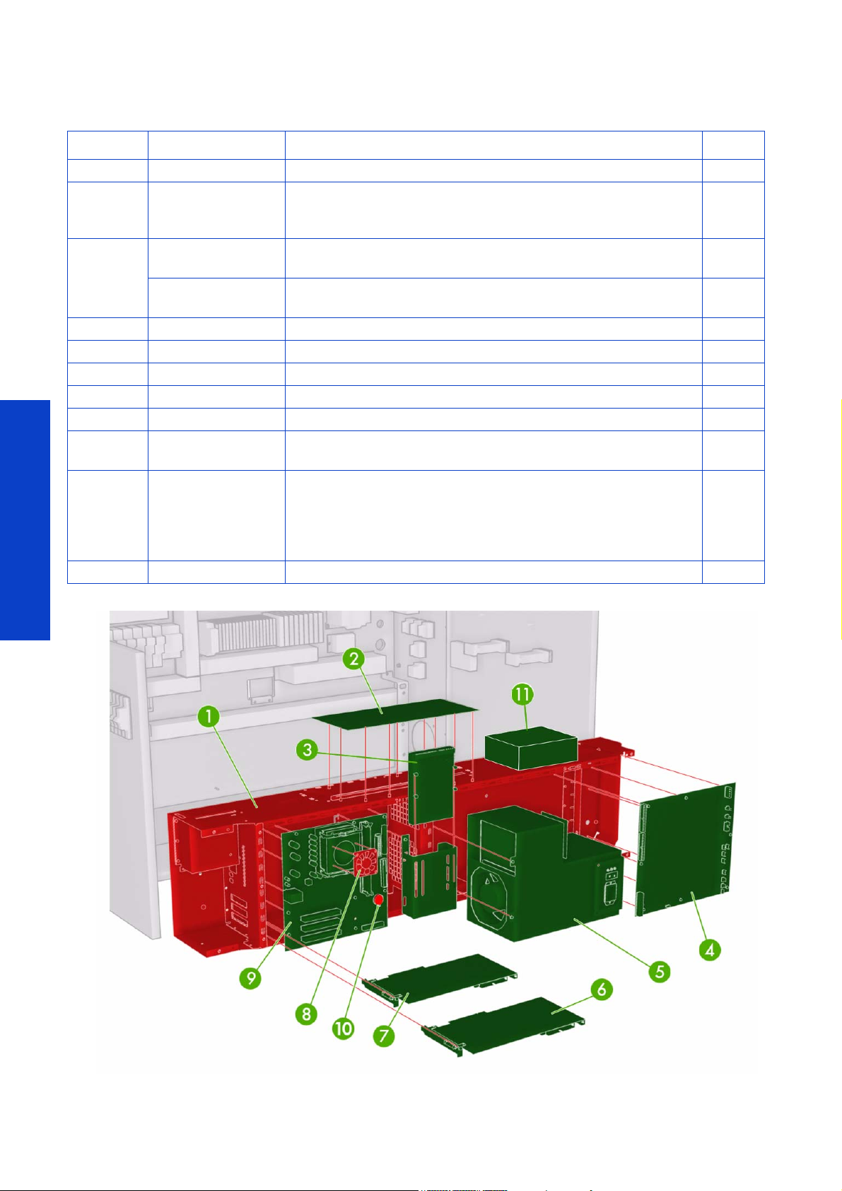
Electronics
Ref HP Part Number Part Description Page
1Q6702-60537 Main Electronics Box 521
Main Interconnect Board
2Q6703-67107
Q6702-60529
3
Q6703-67089
4 Q 670 2- 6 0 5 3 0 P r i n t m e c h B o a r d 514
5 Q6702-60536 Main Power Supply 512
6Q6702-60535 Lower Engine PCI Board 517
7 Q6702-60534 Upper Engine PCI Board 515
8 Q6702-60533 Formatter CPU Fan 511
9Q6702-67006
10 153099-001
11 Q6703-67044 Media output control system (LX800)(includes cables)
(rolled from Q6702-60531, this previous part can still be used on
the LX600/L65500)
Hard Disk System (L65500)(This part can also be used in the
LX600/LX800 but will require a fw upgrade from diagnostics)
Hard Disk System (LX600/LX800)(This part can also be used in the
L65500 but will require a fw upgrade from diagnostics)
Formatter Board (includes Microprocessor and memory
module)(rolled from Q6702-60532)
RTC 3.0V Battery (CR2032) - Lithium disc cell 220mAh, 20mm
diameter, 3.2mm height , small battery of the formatter board. (in
case the P/N is not orderable, and that the customer/customer
engineer cannot provide locally a battery CR2032, order the
complete Formatter board.
520
519
509
Service Parts & Diagrams
450 Service Parts & Diagrams
Page 7

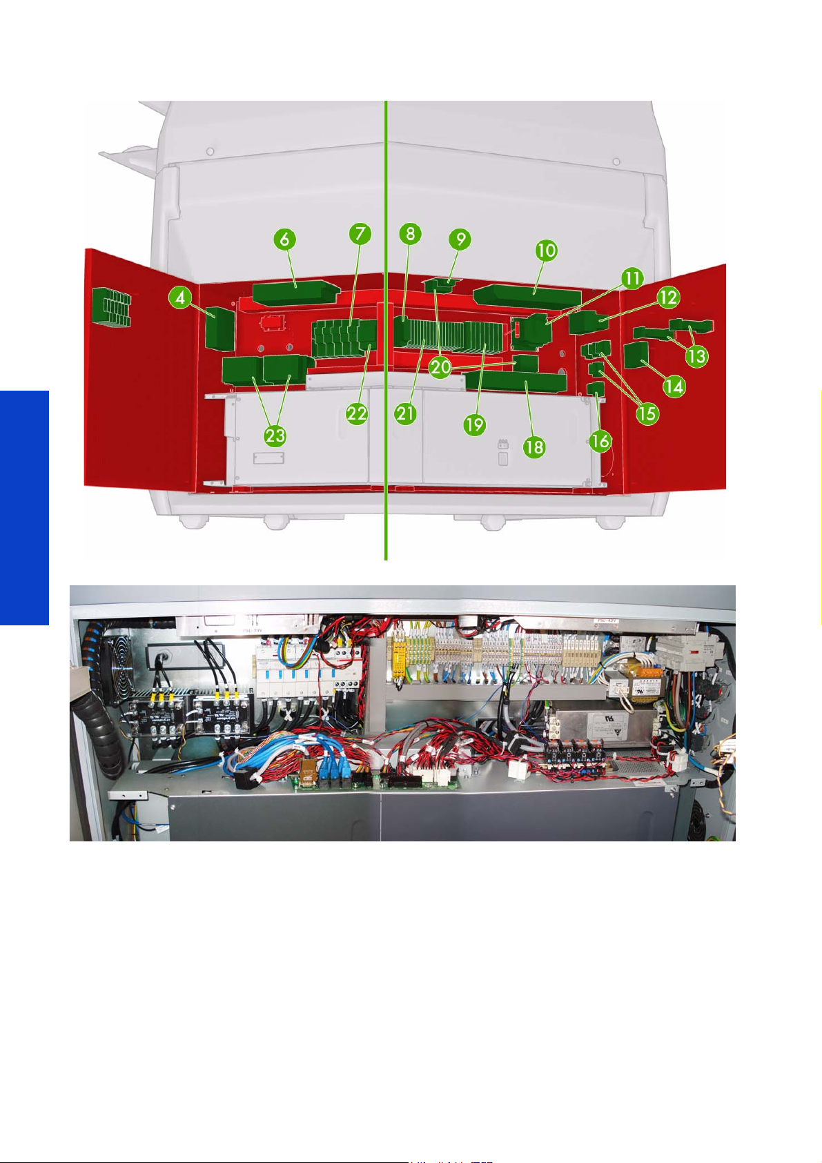
Electrical Cabinet
Ref HP Part Number Part Description Page
4 Q6702-60555
Q6702-60820
5
6 Q6702-60395 Secondary 24 V Power Supply 543
7 Q6702-60394 Power Fuse Holder Block (holds power fuses, not included) 526
8Q6702-60397Safety Relay 542
9 Q6702-60404 Scan Axis Brake Motor Resistor 541
10 Q6702-60396 Secondary 42 V Power Supply 543
11 Q6702-60398 Vacuum Power Transformer 544
12
13
14 Q6702-60557 USB Heating and Curing Communication Box
15 Q6702-60408 Electrical Cabinet Power Light 527
16 Q6702-60406 Electrical Cabinet Power Button and Light 527
18
19 Q6702-60410 Electrical Cabinet Rail Small Fuse Holder (with 1 type of holder) 545
20 Q6702-60400 Single Phase Line Filters 540
21 Q6702-60409 Electrical Cabinet Rail Connector (with 4different holders) 538
22
23 Q6702-60391 Heating and Curing Power Module 535
Not shown Q6702-60554 Electrical Cabinet Low Power Fuse Set (inside number 19)
Not shown Q6704-67002
Q6702-60821
Q6703-67040
Q6703-67041
Q6702-60411 Main Power Switch (L65500/LX600) 528
Q6703-67006 Main Power Switch (LX800) 528
Q6702-60390 Heating/Curing Temperature Controller (L65500/LX600) 529
Q6703-67002
Q6702-60399 3 Phase Line Filter (L65500/LX600) 540
Q6703-67003 3 Phase Line Filter (LX800) 540
Q6702-60407 Main Power Breaker (L65500/LX600)
Q6703-67005 Main Power Breaker (LX800)
Q6702-60389
Q6703-67001
Electrical Cabinet Internal Fan (includes external guard and
filter)(rolled from Q6702-67455)
Power fuse 20A (L65500, LX600)(for 3 phase 3 x 380-415v*)
Power Fuse 32A (L65500, LX600)(for 3 phase 3 x 200-220v*)
Power fuse 25A (LX800)(for 3 phase 3 x 380-415v*)
Power Fuse 40A (LX800)(for 3 phase 3 x 200-220v*)
Heating/Curing Temperature Controller (LX800)(includes current
sensor)
Power Cabinet (includes all upper front of e-cabinet and cables,
does not include e-box)(LX600 color)
Power Cabinet (includes all upper front of e-cabinet and cables,
does not include e-box)(L65500 color)
Power Cabinet (includes all upper front of e-cabinet and cables,
does not include e-box) (LX800)
536
529
546
522
522
Service Parts & Diagrams
*Voltage measured between phase
Service Parts & Diagrams 451
Page 8
Service Parts & Diagrams
452 Service Parts & Diagrams
Page 9
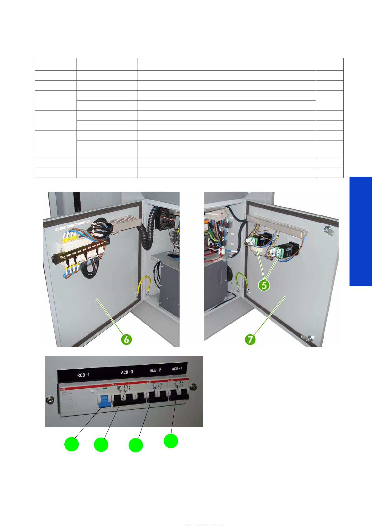
Electrical Cabinet Doors
4
3
2
1
Number HP Part Number Part Description Page
1 Q6702-60402 Circuit Breaker 20A (ACB-1) 536
2 Q6702-60403 Circuit Breaker 10A (ACB-2) 536
3
4
5
6 Q6702-60856 E-Cabinet Right Door (L65500) 525
7 Q6702-67010 E-Cabinet Left Door (includes RCCB 40A)(L65500) 523
Q6702-60401 Circuit Breaker 40A (ACB-3)(L65500/LX600)
Q6703-67004 Circuit Breaker 63A (ACB-3)(L65500/LX800
Q6702-60857 RCCB 40A (L65500/LX600)
Q6703-67048 RCCB 63A (LX800)
Q6702-60390 Heating and Curing Temperature Controllers (L65500/LX600)
Q6703-67002
Heating and Curing Temperature Controllers (LX800)(included
current sensor)
536
529
Service Parts & Diagrams
Service Parts & Diagrams 453
Page 10

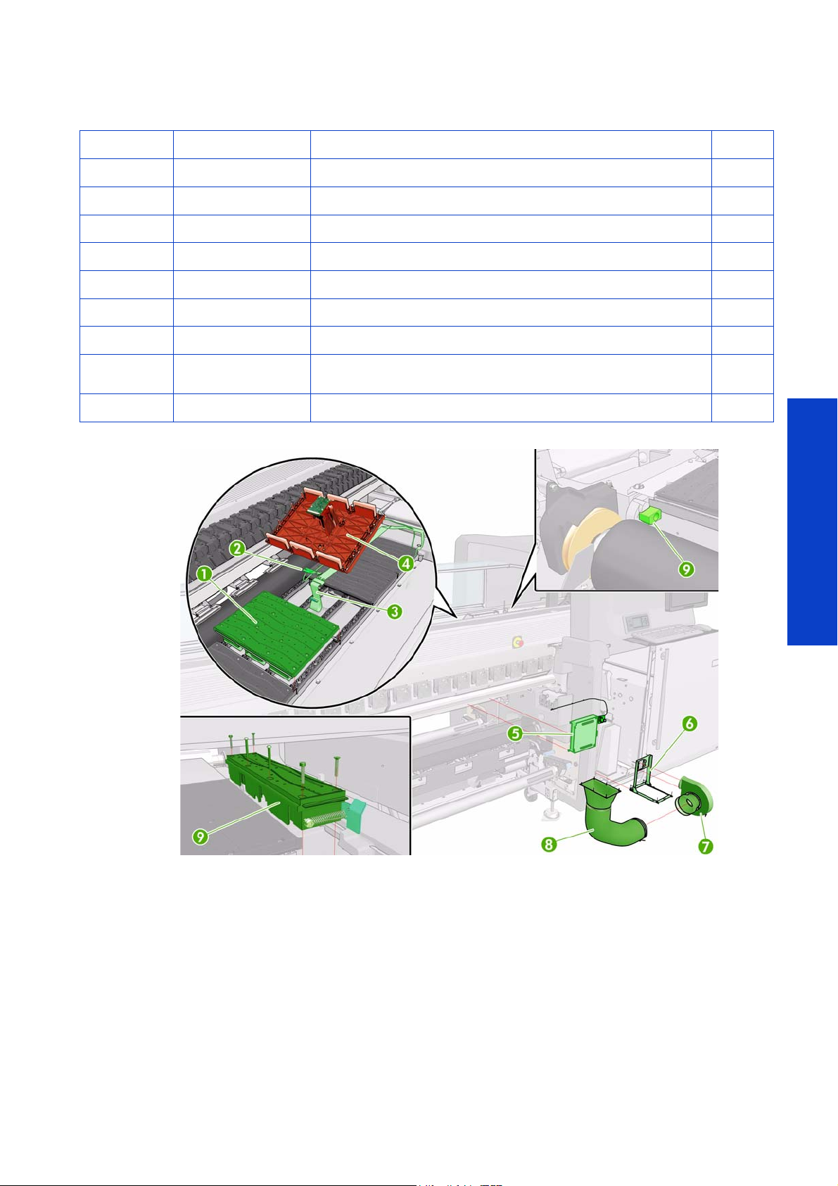
Front Substrate Path (1 of 2)
Ref HP Part Number Part Description Page
1
2
3
4
5
6 Q6703-67104 Curing Bottom Plates Assembly (LX600/LX800)
7
8 Q6703-67105 Curing Bottom Plate Stoppers (LX800) 744
Q6702-60461 Spindle (LX600/L65500)(includes air valve)
Q6703-67062 Spindle (LX800)(includes air valve)
Q6702-60496 Diverter Assembly (L65500) 584
Q6703-67023 Diverter Assembly (LX800) 584
Q6702-60471 Front Left Support Spindle Plate Assembly (L65500) 565
Q6703-67068
Q6702-60472
Q6703-67067
Q6702-60470 Spindle Motor (L65500) (with encoder assembly)
Q6703-67071 Spindle Motor (LX600/LX800)(Red Dot)
Q6702-60497 Diverter Support Bearings Set (LX600/L65500)
Q6703-67024 Diverter Support Bearings Set (LX800)
Front Left Support Spindle Plate Assembly (LX600/LX800/
L65500) (includes Latch Type A)
Front Right Drive Spindle Plate (L65500)(includes the 2 media
output motors)
Front Right Drive Spindle Plate (LX600/LX800)(includes the 2
media output motors)
562
586
9 Q6702-60468 Spindle Latch Type A 568
10 Q6702-60469 Spindle Latch Type B 569
Service Parts & Diagrams
11 Q6702-60559 Emergency Stop Button
12 Q6702-67025 Spindle Air Valve 561
454 Service Parts & Diagrams
Page 11
Front Substrate Path (2 of 2)
Ref HP Part Number Part Description Page
1 Q6702-60538 Platen Assembly 583
2 Q6702-60495 OMAS Temperature Sensor Assembly 578
3 Q6702-60493 OMAS Sensor Cable 573
4 Q6702-60494 OMAS Platen Assembly 571
5 Q6702-60492 OMAS and Vacuum Control Box 577
6 Q6702-60541 Vacuum Pump Support Assembly 581
7 Q6702-60539 Vacuum Pump 580
8Q6702-60540
9 Q6703-67106 Extended platen and stopper (LX800)
Vacuum Tube Assembly (comes with rubber cone connectors for
both ends)
582
Service Parts & Diagrams
Service Parts & Diagrams 455
Page 12

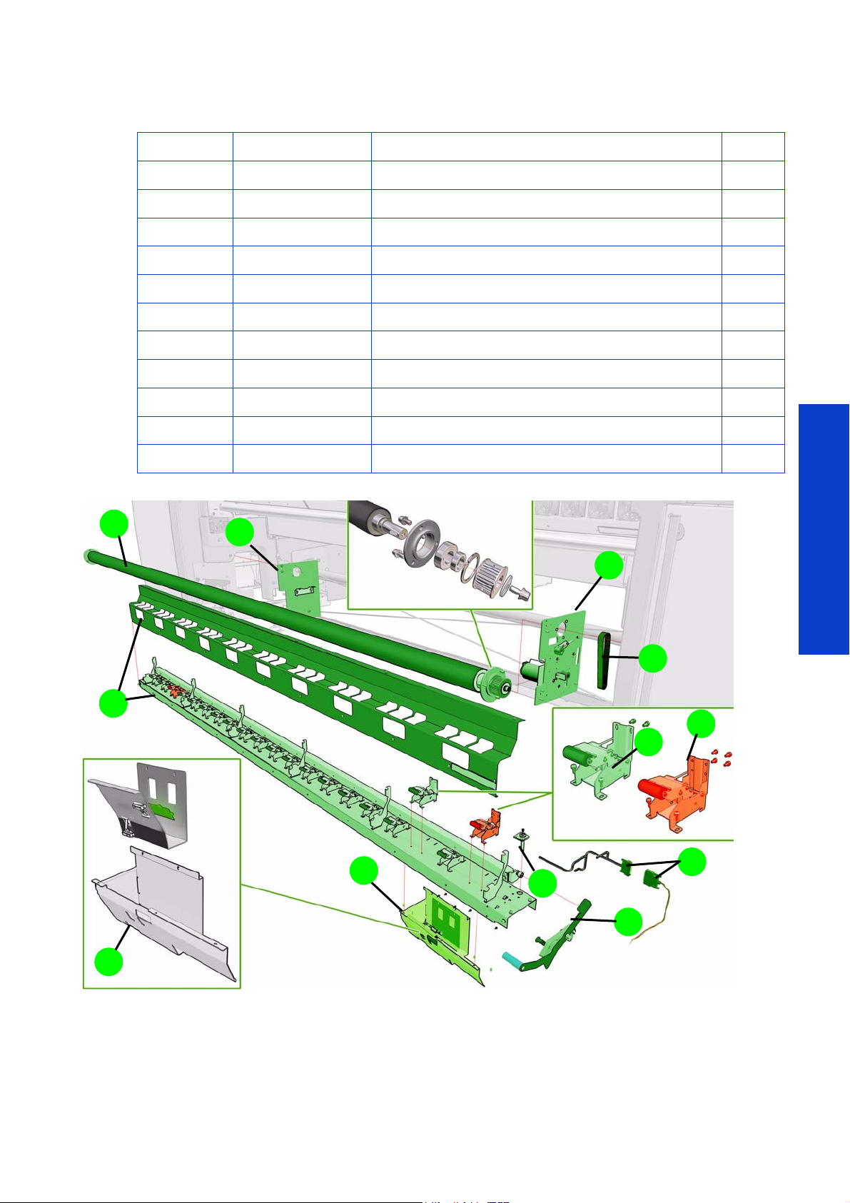
Rear Substrate Path (1 of 2)
Ref HP Part Number Part Description Page
1Q6702-60476
2Q6702-60475 Drive Roller Motor 554
3 Q6702-60474 Drive Roller Encoder Disc and Encoder PCA 552
4 Q6702-60478 Drive Roller Motor Coupling 555
Q6702-60473 Drive Roller Assembly (L65500/LX600)
5
Q6703-67020 Drive Roller Assembly (LX800)
6 Q6702-60477 Drive Roller Support Bearings Set 549
7Q6702-60464 Pneumatic Gun
Drive Roller Transmission Assembly (includes motor, coupling,
encoder reader, mount assembly)
553
547
Service Parts & Diagrams
456 Service Parts & Diagrams
Page 13

Rear Substrate Path (2 of 2)
Ref HP Part Number Part Description Page
1 Q6702-60481 Pinch System Up Retainer 558
2 Q6702-60480 Pinch Wheel 557
3 Q6703-67050
4 Q6702-60483 Pinch Switch Sensor Assembly 558
5
6 Q6702-60462 Spindle Gear and Encup Set (also part of item 8) 560
7 Q6702-67025 Spindle Air Valve (also part of item 8) 561
8
9
10 Q6702-60466
11 Q6702-60469 Spindle Latch Type B 569
12 Q6702-60468 Spindle Latch Type A 568
Q6702-60482 Pinch Support (L65500/LX600)
Q6703-67021 Pinch Support (LX800)
Q6702-60461 Spindle (L65500/LX600)
Q6703-67062 Spindle (LX800)(includes air valve)
Q6702-60467 Rear Right Drive Spindle Plate (L65500)(includes Latch Type A) 566
Q6703-67070 Rear Right Drive Spindle Plate (LX600/LX800)(includes Latch Type A)
Pinch Assembly (roll from Q6702-60479 this previous part can be
used on L65500/LX600)
Rear Left Support Spindle Plate (includes Latch Type B Q6702-
60469)
556
557
559
566
Service Parts & Diagrams
Service Parts & Diagrams 457
Page 14

Dual Roll Assembly & Ink Collector & Diverter
Reference HP Part Number Part Description Page
1 Q6703-67064 Dual Roll Gear (Differential)
2 Q6703-67075 Dual Roll Tool and Screw Protection kit
3 Q6703-67065 Dual Roll End Hub
4
5 Q6703-67086 Dual Roll Rubber Kits
6 Q6703-67088 Loop Shaper Tube Kit (LX800)
7 Q6703-67098 Dual Roll Cap Left
8 Q6703-67097 Right Dual Roll Gear Cap
9Q6703-67061
10 Q6703-67063 Wrinkles Diverter (LX800)
11 Q6703-67047 Ink Collector (includes 1 module, 1 foam)*
12 Q6703-67084 Ink Collector Foam Sets (8 foams)*
13 Q6703-67102 Substrate Diverter Support (LX800)
(*) In case a customer needs to order a complete set of foams, use the part number Q6703-67084, whic h
is NOT covered by the printer warranty, it is a supply as documented in the ‘
Service Parts & Diagrams
shooting guide
the correct part number is the Q6703-67084.
Q6703-67066 Dual Roll Spindle (LX800)(includes item 7 & 8)
Q6704-67001 Dual Roll Spindle (LX600/L65500)(includes item 7 & 8)
’, in the chapter "Replace the ink collector foams", where there is an old part number,
Media Edge Holders (1 set=2 off) (rolled from Q6702-60682,
previous reference can be used on L65500 and LX600)
Maintenance and trouble-
458 Service Parts & Diagrams
Page 15
Roll to Floor Assembly (LX800)
2
3
5
6
7
4
10
6
9
8
11
1
Reference HP Part Number Part Description Page
1 Q6703-67060 Roll to Floor Pinch Mech Assy (includes items 2,3,5,7)
2 Q6703-67092 Roll to Floor Pinch Lever Kit 597
3Q6703-67094 Roll to Floor Damper 592
4 Q6703-67059 Roll to Floor Signal Cable (from Main Interconnect)
5 Q6703-67095 Roll to Floor Pinch Hinge (Outer positions: 4 screws) 596
6 Q6703-67087 Side Plate Left & Right (contains Right Dual Motor) 594
7 Q6703-67076 Roll to Floor Pinch Hinge (Inner positions: 2 screws)
8 Q6703-67058 Roll to Floor Timing Belt 587
9 Q6703-67049 Media Presence Sensor (includes TUR Sensors Cover) 592
10 Q6703-67045 Roll to Floor Roller 587
11 Q6703-67099 TUR Sensors Cover 592
Service Parts & Diagrams
Service Parts & Diagrams 459
Page 16

Ink System (1 of 3)
1
Ref HP Part Number Part Description Page
Q6703-67078
Q6703-67079
Q6703-67080
1
Q6703-67081
Q6703-67082
Q6703-67083
Black Ink Cartridge Connector Set(Rolled from the Q6702-60548,
previous part can also be used on L65500)
Yellow Ink Cartridge Connector Set (Rolled from the Q6702-60549,
previous part can also be used on L65500)
Cyan Ink Cartridge Connector Set (Rolled from the Q6702-60550,
previous part can also be used on L65500)
Magenta Ink Cartridge Connector Set (Rolled from the Q6702-60551,
previous part can also be used on L65500)
Light Magenta Ink Cartridge Connector Set (Rolled from the Q670260552, previous part can also be used on L65500)
Light Cyan Ink Cartridge Connector Set (Rolled from the Q670260553, previous part can also be used on L65500)
598
598
598
598
598
598
Service Parts & Diagrams
460 Service Parts & Diagrams
Page 17

Ink System (2 of 3)
1
2
3
4
5
6
7
8
9
10
Ref HP Part Number Part Description Page
1 Q6702-60426 Ink System LED Interface Board 600
2 Q6702-60430 ISM Air Circuit Module (bottle with cap and 6 mm tubes & fittings) 602
Ink System Pressurization Pump and Relief Valve (2 parts each,with
3 Q6702-60427
4Q6702-60425Ink System Main Board 611
5 Q6702-60424 Ink Sensors Board 609
6 Q6702-60429 ISM Ink Circuit Module 604
7Q6702-60432
8Q6702-67022
9 Q6703-67113 Ink Supply Cartridge Support Tray
10 Q 6702-6 06 87
tubes)(Rolled from Q6702-60547, previous part does not have a relief
valve or a tube.
Intermediate Tank Set (12 tanks) (part number Q6702-60686 is
required to install this part, which is tubes and fittings) ((Need to
remove ink pressure sensor, not calibrated)
3 Ink Pressure sensor mounts (includes tubes, fittings & metal
support)(L65500/LX600)
ISM Ink quick connector repair set (male and female connectors, ink
tubes and fittings to make the repair)
610
Service Parts & Diagrams
Service Parts & Diagrams 461
Page 18

Ink System (3 of 3)
Number HP Part Number Part Description Page
Intermediate tank broken bag repair kit (one intermediate ink tank, air
Q6702-60561
Q6702-60431
Q6702-60686
Q6702-60689
Q6702-60690
Q6702-60433 Ink System Cable Set
Q6702-60560 Intermediate ISS Data Cable (broken bag intermediate tank cables)
Q6703-67127
tube, 7 syringes 7 empty bags4 purgers, 1 purge quick connector,
glovesand fitting)
Syringe Ink System Purge Kit (contains 6 empty bags, 7 syringes with
needles and tube, 4 orange ‘setup printheads’, the intermediate quick
connector (to be able to fill-in only the ISM, without the TRS).
ISM Repair Kit (1 Electrovalve, 2 Check Valves (4 way valves), tubes
and fittings for the rapair, tube cutter, 6 O rings for the ink pressure
sensor, ink leak cable, connections)
TRS Repair Kit (two backflow valves, ink tubes, and all required
fittings. Used to repair leaks in the TRS [carriage chain assembly])
Ink System Tubes Cleaning Tool (used to flush the ink system)(includes
special pump, 1 intermediate ink tank, 1 syringe, 1 empty cartridge
bag)
Kit of 3 ink electrovalves with all the corresponding fittings (to be
available by end of Fall 2010, in the meantime, continue to order the
ISM repair kit)
Service Parts & Diagrams
462 Service Parts & Diagrams
Page 19

Scan Axis (1 of 3)
Ref HP Part Number Part Description Page
1 Q6702-60439 Scan Axis Belt Tensioner 625
2 Q6702-60434 Scan Axis Impelling Belt (L65500/LX600) 623
2 Q6703-67010 Scan Axis Impelling Belt (LX800) 623
Q6702-60435 Scan Axis Encoder Strip (includes encoder reader)(L65500/LX600) 631
3
4
5
6Q6702-60688
7Q6703-67126
Not shown
8
Q6703-67011
Q6702-60484
Q6703-67022
Q6702-60440 Scan Axis Tube Shelf (L65500/LX600) 626
Q6703-67013 Scan Axis Tube Shelf (LX800) 626
Q6703-67108
Q6703-67109
Q6702-67030
Q6702-67029
Q6702-60436
Q6703-67012
Scan Axis Encoder Strip (includes encoder reader)(LX800, can be
used on L65500/LX600 by cutting the encoder strip)
Carriage Chain Assembly (includes tubes, power and data
cables)(L65500/LX600)
Carriage Chain Assembly (includes tubes, power and data
cables)(LX800)
TRS Print Head Ink Connectors Repair Set (includes fittings, 8
cables, and FI towers)
FI Towers Kit (rolled from Q6703-67111, increased reliability, 1 kit
contains 6 FI tower)
Single Data Trailing Cable (Connected to Yellow/Magenta)(LX800
can be used L65500/LX600)
Double Data Trailing Cable (Connected to Light Cyan/Light
Magenta & Cyan/Black)(LX800 can be used L65500/LX600)
Single Data Trailing Cable (Connected to Yellow/
Magenta)(L65500/LX600)
Double Data Trailing Cable (Connected to Light Cyan/Light
Magenta & Cyan/Black) L65500/LX600)
Scan Axis Encoder system and support (includes encoder strip and
8 metal supports and screws)(L65500/LX600)
Scan Axis Encoder system and support (includes encoder strip and
8 metal supports and screws)(LX800)
628
628
686
660
Service Parts & Diagrams
Service Parts & Diagrams 463
Page 20

Scan Axis (2 of 3)
Ref HP Part Number Part Description Page
1
2 Q6702-60490 PPS Low Switch 652
3 Q6702-60487 PPS Motor Assembly 649
4 Q6702-60486 Remote Controller Board (PPS) 648
5 Q6702-60489 PPS Screw Assembly 650
Q6702-60488 PPS Motor Mount Assembly Type L (front left & rear right)) 649
Q6702-60491 PPS Motor Mount Assembly Type R (front right & rear left) 649
Q6702-60485 PPS Cables Set repair kit
Q6702-67011
Q6702-60689
TRS dynamic Tubes replacement to be used when ‘Preventative
Maintenance #5’ is displayed (L65500)
TRS Repair kit (2 back-flow/anti-return valves, ink tube and all
fittings, this is used to repair any ink leak from a quick connector
to IGUS chain.
614
Service Parts & Diagrams
464 Service Parts & Diagrams
Page 21

Scan Axis (3 of 3)
10
Reference HP Part Number Part Description Page
1 Q6702-60418 Printhead Capping Module 643
2 Q6702-60416 Service Station Connection Board 634
3 Q6702-60415 Drop Detectors Set (3 off) 635
4 Q6702-60419 Service Station Screw Assembly 641
5Q6702-60414 Service Station Motor 638
6 Q6702-60417 Remote Controller Board (Service Station) 637
7 Q6702-60413 Service Station Encoder Strip and Sensor
8 Q6702-60412 Service Station Chassis 639
9 Q6703-67074
10 Q6702-60438 Scan Axis Motor Cable Set repair kit (Data and Power cables)
Scan Axis Motor (with 3 ohm resistance) (Rolled from Q670260437, this previous part can be used on the L65500)
620
Service Parts & Diagrams
Service Parts & Diagrams 465
Page 22

Carriage Assembly
17
18
19
Reference HP Part Number Part Description Page
1 Q6702-60510 Carriage Tower Assembly 681
2/7 Q6702-60511 Aerosol Removal Box Assembly (includes fans) 674
3 Q6702-60504 Carriage Oiling Foam Retainer and Rear Support Set 678
4 Q6702-60501 Pen Pocket Kit 654
5 Q6702-60507 Primer Assembly (includes latch and labels) 672
6 Q6702-60506 Carriage Printhead Interconnect 658
8 Q6702-60505 Carriage Encoder Set (Encoder reader) 655
9 Q6702-60508 Carriage Lid 679
10 Q 6703- 67117
11 Q6702-60512 Carriage Interconnect Board 672
12 Q6702-60498 Carriage Assembly
14 Q 6702 - 6 0 5 0 0 L i n e S e n s o r A s s e m b l y 671
13 Q6702-60509 Carriage Lid Switch 680
15 Q6702-60499 Carriage Sensor Box 659
16 Q6702-60861 Carriage front bushing service kit (includes all sub assembly)
17 Q6702-60502 Carriage Cable Set (2 data cables & 3 power cables)
18 Q6702-60503 Carriage Oiling Foam Retainer Lid 677
19 Q6702-60858
Service Parts & Diagrams
Not shown Q6703-67118
Not shown Q6703-67126
Carriage Oiling Foams Kit (kit of 2 oily foams, will be available
from fall 2010, in the meantime, order the Cleaning Kit)
PH Interconnect protection kit (includes all 3 PCAs, mylar & metal
support)
Rear Carriage Bushing (includes Wicks & Felts Kit) + 2 oily foams
+ bottle of oil (Available fall 2010, before this order the carriage
assembly).
FI Tower kits (roll from Q6703-67111, increase reliability, 1 kit
contains 6 FI tower).
690
466 Service Parts & Diagrams
Page 23

Printhead Cleaning Assembly
Ref Part Number Part Description Page
1 Q6702-60442 Printhead Cleaner Roll Driver Assembly 705
2 Q6702-60445 Printhead Cleaner Roll Belts Set (includes the belt only) 704
3Q6702-67014
4Q6702-67018
5 Q6702-60448 Printhead Cleaner Roll Support Kit (core) 710
6Q6702-67019
7Q6702-60449
8 Q6702-67024 Printhead Cleaner Roll Pinch Assembly (roll from Q6702-60447) 708
9Q6702-67020
10 Q6702-60685 PH Cleaner Waste Bottle
11 Q 6 7 0 3 - 6 7 0 7 7
13 Q 6 70 2 - 6 0 4 41
14 Q6703-67090
Q6702-67013 Grease kit for the Printhead cleaning rollers
Not
shown
Q6702-67012
Printhead Cleaner Roll Rubber Roller (may include small plastic stars)(roll from
Q6702-60443)
Printhead Cleaner Roll Rubber Roller Up/Down Assembly (roll from Q670260444, the new part include shaft)
Printhead Cleaner Electrobrake (includes small gear & shaft)(Rolled from
Q6702-60683)
Printhead Cleaner Chassis (includes the complete assembly, except Media
Advance motor, Cleaner Roll & Rubber Roll, cable kit, up/down motor, tension
belts.
Printhead Cleaner Motor Assembly (includes the white main gear)(roll from
Q6702-060487, the previous part is still used as the motor of the PPS/Scan
Beam)
PH Cleaner Rollers encoder (includes a connector to be compatible with older
versions)(roll from Q6702-60684, this previous number is not compatible with
new PH Cleaner Assembly)
Printhead Cleaning Roller Module (to be used only if previous repair failed9
(includes shims)
Gears kit (includes main gear connected to the 2 belt with the upper and
lower clutch, axis of the electromechanical brake and 4 small gears (2 types
of inner hole: 3 with an 'oval' shape and 1 with the round shape)(Rolled from
Q6702-67015)
Shims: Calibration kit (to be used for Calibration 4.7.3)(Printhead cleaner
Adjustment Shims) (includes 3 shims)
706
707
711
441
720
439
Service Parts & Diagrams
Service Parts & Diagrams 467
Page 24

Heating Module
Reference HP Part Number Part Description Page
1
2
3 Q6702-60459 Temperature Sensor (1 off)
4 Q6702-60454 Star - Triangle Configuration Box Set
5 Q6702-60458 Heating Supports Set 742
6
Not shown
Q6702-60456 Heating and Curing Resistor Set (3 off) (L65500/LX600)
Q6703-67017 Heating and Curing Resistor Set (3 off) (LX800)
Q6702-67005 Heating Safety Thermostat (L65500/LX600) 743
Q6703-67042 Heating Safety Thermostat (LX800)
Q6702-60457
Q6703-67018 Heating Module Assembly (2 additional resistors) (LX800) 737
Q6703-67115 Drying cable cable set (LX800)
Q6704-67004 Drying cable cable set (L65500/LX600)
Heating Module Assembly (2 additional resistors) (L65500/
LX600)
731
740
736
743
734
742
737
Service Parts & Diagrams
468 Service Parts & Diagrams
Page 25

Curing Module
Reference HP Part Number Part Description Page
1
2 Q6702-60452 Curing System Fan (1 off) 734
3
4
5Q6702-60455
6 Q6702-60454 Star - Triangle Configuration Box Set
7
Not shown
Q6702-60450 Curing Module Assembly (2 additional resistors)(LX600/L65500) 729
Q6703-67014 Curing Module Assembly (2 additional resistors)(LX800) 729
Q6702-67016
Q6703-67114
Q6702-60456 Heating and Curing Resistor Set (3 off) (L65500/LX600)
Q6703-67017 Heating and Curing Resistor Set (3 off) (LX800)
Q6702-60463 Front Top Power Cable (LX600/L65500)
Q6703-67056 Front Top Power Cable LX800)
Q6702-60453 Curing Module Cable Repair Set (LX600/L65500)
Q6703-67016 Curing Module Cable Repair Set (LX800)
Q6702-60451 Fan Array Cable (not shown)(LX600/L65500)
Q6703-67015 Fan Array Cable (not shown)(LX800)
Curing Cable Cover Set(metal covers located at the top of the
Curing fans, left, middle and right)(LX600/L65500)
Curing Cable Cover Set(metal covers located at the top of the
Curing fans, left, middle and right)(LX800)
Curing Safety Thermostat (LX600/L65500) (For the LX800 the
thermostat is only availble from the Curing Module)
731
74 0
735
734
742
Service Parts & Diagrams
Service Parts & Diagrams 469
Page 26

Internal Print Server PC
For more information, see Internal Print Server PC on page 776.
When the printer is out of warranty, the following parts of the PC can be ordered from the following web site:
www.hp.com, support and drivers, np5700 and click on search and then search for ‘how to order parts’
In some territories these parts can be also ordered through partsurfer.hp.com..
HP Part Number Part Description
Internal Print Server PC (rolled from FN886PA #AB4) The IPS PC which can have VISTA + IPS (L65500
configuration) or Win7 + IPS + Antivirus + PrintCare (LX printcares configuration).
Q6702-67026
HP part Number: Recovery
DVD (no P/N available)
Q6702-67027 Monitor (rolled from KR145AA#AB$
Q6702-60544
Q6703-67100 Web Cam
Q6703-67101 Web Cam USB Extension Cable
440499-001 IPS PC HDD (160GB)
445759-001 Front USB device with cable
445760-001 Power switch/LED assy with cable
445777-001 Expansion card cable kit
445763-001 SATA drive cable kit
Service Parts & Diagrams
419496-001 16X SATA DVD-ROM drive
435382-B31 USB, Basic Vista, international version,
434820-251 USB, Basic Vista, Russian version,
445765-001 Hood assembly with front bezel
445771-001 Power supply, 80Plus
445757-001 Standard system board
445764-001 Standard system board for Russia
450470-001 Intel Core 2 Duo Processors 2.13GHz
398038-001 Memory 1 GB, PC2-5300, CL5
445758-001 Riser card with mounting bracket and screws
445761-001 Chassis fan
445774-001 Heatsink with alcohol pad and factory-applied thermal grease
417966-001 Mouse, PS2, optical
153099-001 Battery, real-time clock
445766-001 Front bezel without mounting screws
445762-001 Internal speaker
445767-001 Fan duct
445770-001 Tower stand
In case the support part does not correspond with the previous IPS PC configuration, reinstall the IPS PC
following the information available at the end of the chapter 6 of the service manual and use the DVDs provided
with the initial printer.
In case there is a need to get the origicanl DVDs: contact the specific support of the HP PC, contact information
available within the documentation of the IPS PC, or from the www.hp.com -> Contact Customer Support ->
Contact HP and once you are in contact with a call agent, request a copy of the recovery cd for the model of the
IPS PS (HP rp5700) and provide the S/N of the IPS PC (marked at the back of the PC). In some regions there
may be no availability, in this case order the complete Internal Print Server PC which comes with the recovery
DVD.
HP Pressure Switch 1400-8G (Rolled from J9077A#ABA) Includes also the power cord ecabinet switch and the
2 LAN cable PC switches and ecabinet switch; initially this part had only the cables but now all support parts
also include the switch inside the box.
470 Service Parts & Diagrams
Page 27

Cables
For cables linked within a specific sub assembly, refer to the corresponding sub assembly
HP Part Number Part Description
Front Data Bundle Cables (L65500/LX600)
•
Q6702-50018: Vacuum control to Pump cable
• Q6702-50060: Main Interconnect to Vacuum Ctrl PCA data cab
• Q6702-50066: Top Door Switch cable
Q6702-60543
Q6703-67037
• Q6703-50021: Main Interconnect -PPS data cable
• Q6703-50023: Main Interconnect - Front Spindle motor system cable
• Q6703-50026: Main Interconnect - Capping station Remote controller PCA data
• Q6703-50028: Main Interconnect -Far PPS Data
• Q6703-60173: Front Panel Cable
Front Data Bundle Cable (LX800)
•
Q6702-50018: Vacuum control to Pump cable
• Q6702-50060: Main Interconnect to Vacuum Ctrl PCA data cab
• Q6702-50066: Top Door Switch cable
• Q6703-50081: Main Interconnect -PPS data cable
• Q6703-50096: Main Interconnect - Front Spindle motor & Roll to Free Floor
• Q6703-50026: Main Interconnect - Capping station Remote controller PCA data
• Q6703-50028: Main Interconnect -Far PPS Data
• Q6703-60173: Front Panel Cable
Q6702-60556 Electrical Cabinet to Main interconnect Cable
Emergency Stop Cable (LX600/LX800/L6500)
•
Q6702-60558
Q6702-60560
Q6702-60562 Main Electronics Box Power Cable
Q6702-60563
Q6702-60564 Vacuum Pump Cables (Power and Data cable)
Q6702-60565
Q6702-50033E-stop to e-cabinet cable (2 off)
• Q6702-50034E-stop cable (3 off)
Intermediate ISS Data Cable (Broken bag Intermediate Tanks cables,
2 off)
Main Electronics Box Cable Set
•
Q1271-60249: Cable PrintMech - Engine PCI (A)
• Q1271-60259: Cable HDD IDE
• Q1271-60366: Cable PrintMech - Engine PCI (B)
• Q1271-60653: Cable Engine PCI - Main interconnect
• Q6703-60180: Formatter- Main interconnect Front Panel cable
• Q6703-60181: Engine PCI -Main interconnect encoders cable
• Q6703-60183: Power distribution cable
Back Data Bundle
Q6703-50021: Main Interconnect - PPS data cable
•
• Q6703-50022: Main Interconnect - MI cable
• Q6703-50021: Main Interconnect - PPS data cable
• Q6703-50022: Main Interconnect - MI cable
Service Parts & Diagrams
Service Parts & Diagrams 471
Page 28

Back Power Bundle (LX600/LX800/L65500)
•
Q6702-50019: Vacuum power cable
Q6702-60566
• Q6702-50048: Main Interconnect Power near back cable
• Q6703-50025: Main Interconnect power far cable (LX600/L65500)
• Q6703-50044: Media Drive Motor Cable
• Q6703-50045: Cable PrintMech -Rear Spindle system motor
Q6703-67116 Power FAR PPS & ISM cables (LX800)
Q6702-60568
Q6702-60569 PC and Monitor Power Cords
Q6702-60460
Q6703-67019
Q6702-60463
Service Parts & Diagrams
Q6703-67114
Q6702-60433
Q6702-60567
Main Power Cords (3 phase & single phase external power
cords)(L65500/LX600)
Front Power Bundle (LX600/L65500)
•
Q6702-50047: Main Interconnect Power near front
• Q6703-50046:Cable Print Mech-Front Spindle System motor (PWM). PID
controller to the temperature sensor cable
Front Power Bundle (LX800)
Q6702-50047: Main Interconnect Power near front
•
• Q6703-50046:Cable Print Mech-Front Spindle motor (PWM) & Roll to Free Floor).
PID controller to the temperature sensor cable
Front Top Bundle (LX600/L65500)
•
Q6702-50014: IR Temperature Sensor Cable
• Q6702-50033: E-stop to e-cabinet cable*
• Q6702-50036: Grounding cable long
• Q6702-50045: Curing to e-cabinet (LX600/L65500)
• Q6703-50050: Main Interconnect - Vacuum-OMAS controller cable
• Q6703-50051: Main Interconnect - Heaters interconnect box (LX600/L65500)
*Includes the cable going from the IR temperature sensor connection on the scan beam
to the PID temperature controller & Main Interconnect board.
Front top bundle (LX800)
•
Q6702-50014: IR Temperature Sensor Cable
• Q6702-50033: E-stop to e-cabinet cable*
• Q6702-50036: Grounding cable long
• Q6702-xxxxx: Curing to e-cabinet (LX800)
• Q6703-50050: Main Interconnect - Vacuum-OMAS controller cable
• Q6703-xxxx: Main Interconnect - Heaters interconnect box (LX800)
*Includes the cable going from the IR temperature sensor connection on the scan
beam to the PID temperature controller & Main Interconnect board.
Ink system cable set
•
Q6702-50027: Broken Bag Int Tank Cable (2 Off)
• Q6703-500583: ISM Front bundle set
• Q6703-500593: ISM Rear bundle set
Printhead Cleaner Cables
•
Q6703-50020: Printhead cleaner - Main Interconnect Data Cable
• Q6702-50048: Printhead cleaner - Main Interconnect Power Cable
• Q6702-50022: Printhead cleaner Internal Data Cable
• Q6702-50023: Printhead cleaner Internal Power Cable
• Q6702-50024: Advance Motor - Differential PCA encoder Cable
• Q6703-60195: Linear to Differential encoder PCA (2 Off).
See note below.
a
472 Service Parts & Diagrams
Page 29

a. note that a new version of the encoder reader will come with the new version of cable. In
case this new cable is used within a PH cleaning roller with a previous version of cable
and encoder reader -> the encoder reader also has to be replaced. All information available about the different versions of encoder reader available within the the 'PH cleaning
roller encoder reader replacement chapter.
Additional Parts
HP Part Number Part Description
Q6702-60544 LAN cable + power cable (Includes the 1GB Switch)
Q6702-60546
Q6703-67096 Labels Kit 126(LX800)
Q6702-60656
Q6702-60860
Q6702-67013
Q6702-60839 Repackaging Kit (for transportation) (LX600/L65500)(through escalation only)
Q6703-67051 Repackaging Kit (for transportation) (LX800) (through escalation only)
Q6703-67093
Grease Kit (for Scan beam columns and Carriage rails, not for the Printhead
Cleaning Rollers)
Cleaning Kit (L65500) Can also be used on the LX600/LX800 but in addition to
the grease kit Q6702-67013.
Labels kit, Service (includes all labels, product label without the SN printed, this is
to be added when it is placed on the printer).
Grease kit for Printhead Cleaning Rollers, & O ring of the Primer, under the latch
of the Printheads. Rolled from Q6702-67013.
Up time kit. Includes pen capping module, ink pressure sensor board, pinchwheel,
Carriage sensor box, Carriage Interconnect board, Carriage Printhead
Interconnect board, Main Interconnect board, ISM repair kit, power fuse 20A,
25A, 32A, 40A, printhead cleaning roller gears kit, pinchwheel assembly, media
edge holder (2 off), hard disk drive, temperature sensor, FI tower, single and
double data trailing cables, heating/curing resistance sets for LX600/L65500/
LX800
Service Parts & Diagrams
Service Parts & Diagrams 473
 Loading...