

Page 1

1 Printer systems
• Electrical system.....................................................................................................4
• Ecabinet.........................................................................................................5
• E-Box ........................................................................................................... 19
• ECabinet Circuit Diagrams ..................................................................... 10
• PCA Boards and connections..........................................................................20
• Formatter PCA...................................................................................... 20
• Hard disc drive..................................................................................... 20
• Upper and Lower Engine PCI Board ........................................................ 20
• Printmech Board ................................................................................... 21
• Main Interconnect Board connections ...................................................... 22
• Substrate path ..................................................................................................... 28
• Ink System........................................................................................................... 39
• Scan Axis ........................................................................................................... 45
• Carriage............................................................................................................. 57
• Printhead Cleaning System.................................................................................... 61
• Heating and Curing .............................................................................................66
• User Interface ...................................................................................................... 74
Printer Systems
Printer systems 3
Page 2
Electrical system
The electrical system is primarily housed in the electrical cabinet, inside this is the electronics box.
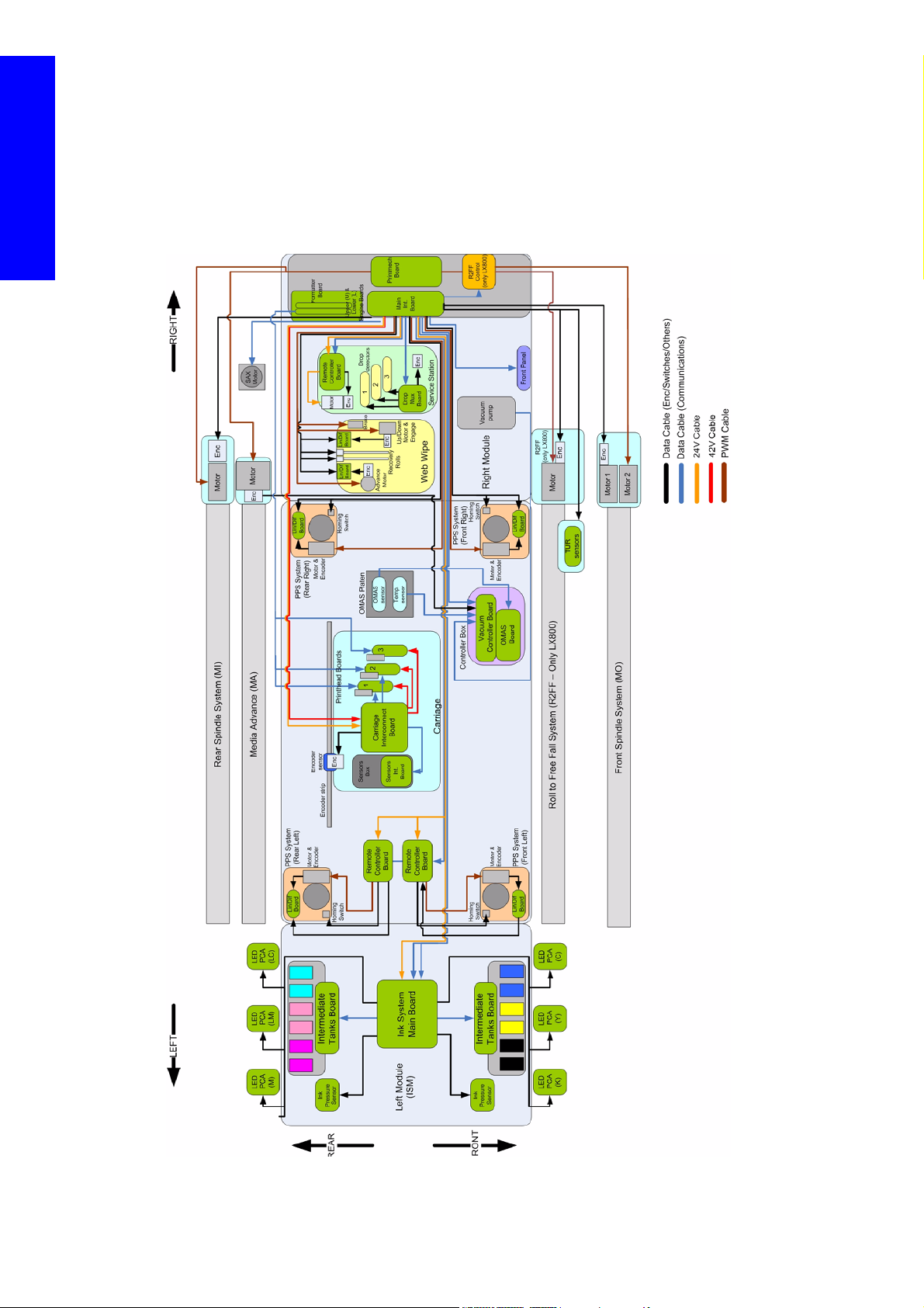
Electronics overview diagram
The following diagram explains the connections between components and electronic boards, the voltage,
Printer systems
or the type of data line.
4 Printer systems
Page 3
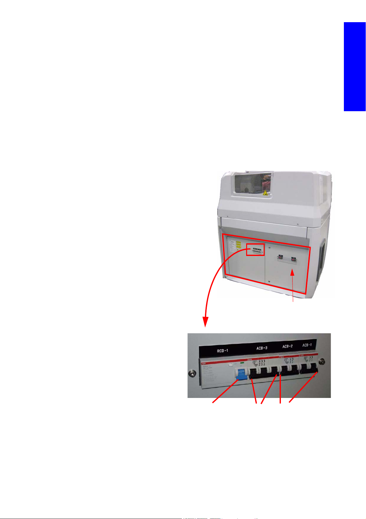
Ecabinet
The ECabinet
ACB-3
ACB-2
ACB-1
3 phase
Circuit
breaker
Single phase
Circuit breaker
RCD-1
Residual
Current
Circuit
Breaker
(RCCB)
The ECabinet located on the right side of the printer and is the enclosure where the main electronics
(Electronic Control System, E-box) and all the power electrical components of the printer are located. The
system if fed via two power lines, one single phase line and another tri-phase line see the Installation Guide
and Site Preparation guide for specifications.
The E-Cabinet responsible for distributing all the power lines to the functional areas, it includes the active
power elements of the heating and curing subsystem. It also performs safety cut-outs when any of the four
emergency stops are pushed
Some of the components inside the e-cabinet are independent units isolated from the electronics therefore
diagnosing any issues via Firmware is not possible.
To diagnose most electrical issues, voltage and continuity checks are required from the Service Engineer
by using multi-meter tools (Voltmeter, Amp meter, resistor meter, continuity checks)
Components
The Ecabinet contains the following
components:
• The Ebox
• Secondary 24v Power supply
• Secondary 42v Power supply
• Circuit breakers & Residual Current Circuit
• Contactor (Heating and Curing)
• Fuses (Heating and Curing)
• E-Box system (which includes a main
• Safety relay
• Fan
• Scan Axis break resistor
• Vacuum system transformer (110v)
• Main switch
• Power Enable button
• Light indication for Phases
• 3 Phase Line filter
• 1 Phase Line filter
Printer systems
breaker (RCCB)
power supply delivering ATX tensions and
also 24V and 42V)
Printer systems 5
Page 4
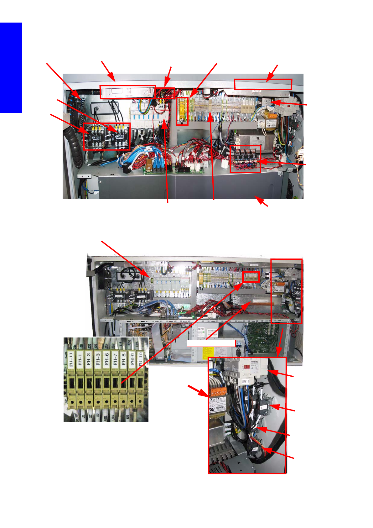
Inside the ECabinet (1 of 2)
Ebox
Secondary 24v supply
Secondary 42v supply
Heating
and
Curing
Power
Modules
(power
lines are
thicker in
the LX800)
Safety Relay
Contactor
RM 3 Phase
Terminal
Blocks
ECabinet
fan
1 Phase
Line filter
Line filter 42v
line +resistors
Roll to Free
Floor
control
system
LX800
Power fuses heating/
Curing
Fuse block (1A, 2A, 4A
3 Phase line filter
Power enable
button
Vacuum power
On
Vacuum
transformer 110v
Main switch
Light indicator
for phases
Printer systems
Inside the ECabinet (2 of 2)
6 Printer systems
Page 5

Ecabinet Fuse blocks
Fuse Application
• Fuses: 1,2,3 (1A) Indicator Lamps
• Fuses 6, 7 (1A): PID controllers
• Fuse 8 (2A): Phase 110 from Trafo to Pump
• Fuse 9 (2A): Neutral 0V from Trafo to Pump
• Fuse 10 (4A): protects 110V transformer
• Fuse 11 (2A): 24V from Main interconnect to e-cabinet
Functionality
1. The E-Cabinet is the power distribution centre for the whole printer
It is the central point where both input power lines (Single and tri-phase) are connected and then distributed
to the different power components.
Single Phase components powered through ACB1
• Heating Controller Module
• Curing Controller Module
• Secondary 42V power supply (SAX motor, Media Path Motors)
• Secondary 24V power supply (Curing Fans)
• Vacuum Fan
• E-Box
Printer systems
Single Phase components powered through ACB2
• Printer PC (Windows, IPS)
• Printer Monitor
• Printer Switch
Tri-Phase components powered through ACB3 and RCCB
• Heating and Curing Power modules – Heating and curing lamps
- Contains the Ebox
- Emergency stop mechanism for the machine.
- Heating and curing control and power distribution.
Printer systems 7
Page 6
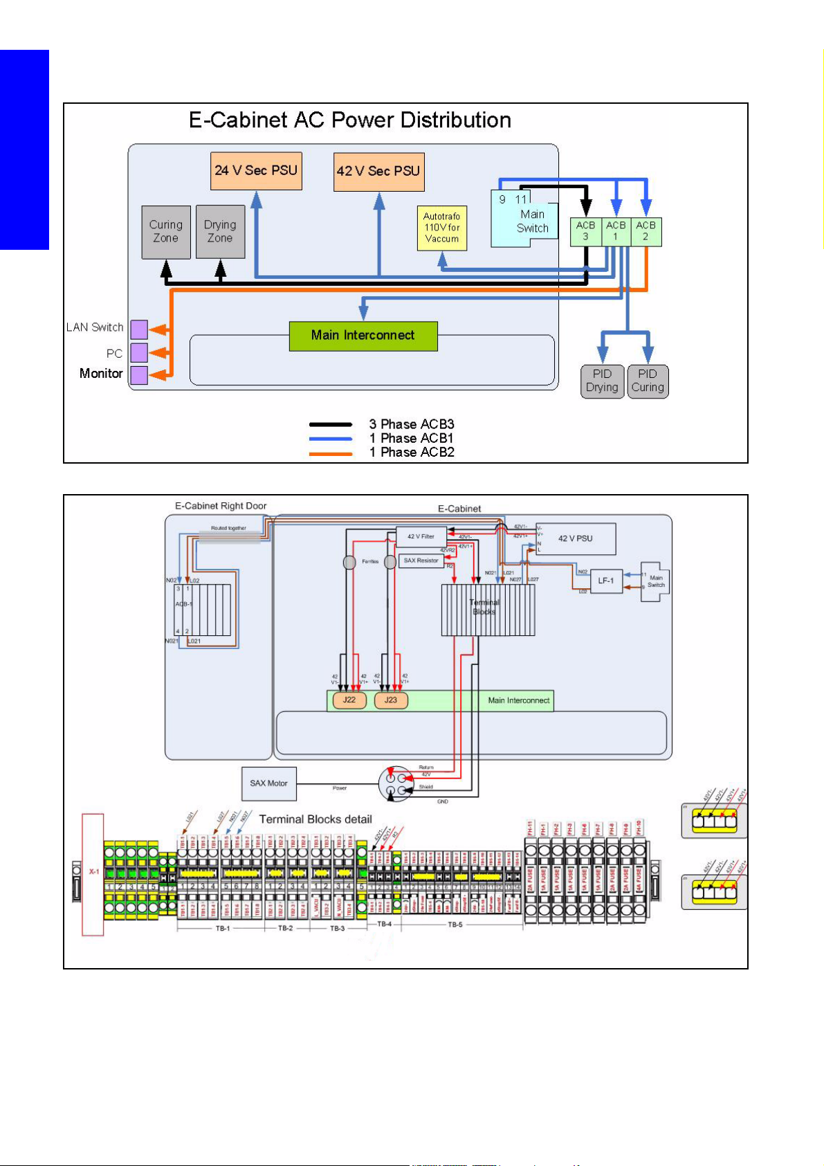
ECabinet electrical overview
Printer systems
42v Secondary Power Supply, Power distribution diagram
8 Printer systems
Page 7
Functionality interlinked between diagrams
Power
Fuses
Heating
Line
Filter
Main
Switch
Circuit
Breaker
Contactor
KM SW-1
Power
Module
Heating
Heating
Configuration Block
(star/triangle)
Lamps
Heating
Power
Fuses
Curing
Power
Module
Curing
Curing
Configuration Block
(star/triangle)
Lamps
Curing
A. 3 phase power supplied to the Heating and curing Modules through the power fuse blocks (FH4,
FH5):
B. Single phase power distribution.
C. 42v secondary power supply actuation (by safety relay)
D. Power modules control signals from PID controllers.
E. Safety line connections (cuts connector of the 3 phase line).
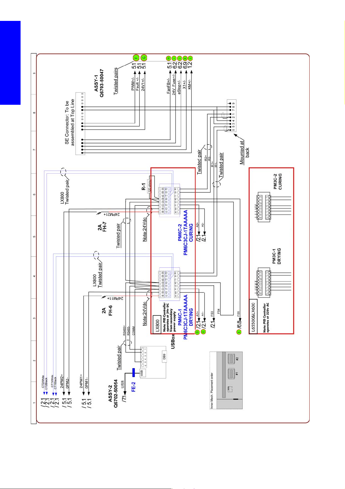
F. PWM signal and fault from curing fan array to Main Interconnect (24v power is directly supplied
from 24 volt secondary PSU).
G. 24v fault signal to the Main Interconnect (this line is used to detect if the 24v secondary power
supply is providing 24v or not).
H. E-cabinet internal fan fault signal to Main Interconnect (fault reported when fans do not rotate when
powered).
Printer systems
I. 24v fused line arrival to the e-cabinet from the Main Interconnect.
J. E-stop 24v power line (these 24v activate the safety relay).
K. Feedback to the Main Interconnect safety relay is active (with negative logic). This indicates the
printer is armed from the circuit breakers.
L. KM Contact active (closed). Feedback to the Main Interconnect.
In the following pages are the printers circuit diagrams. Refer to the circled numbers and letters to jump
from one circuit diagram to another.
Printer systems 9
Page 8
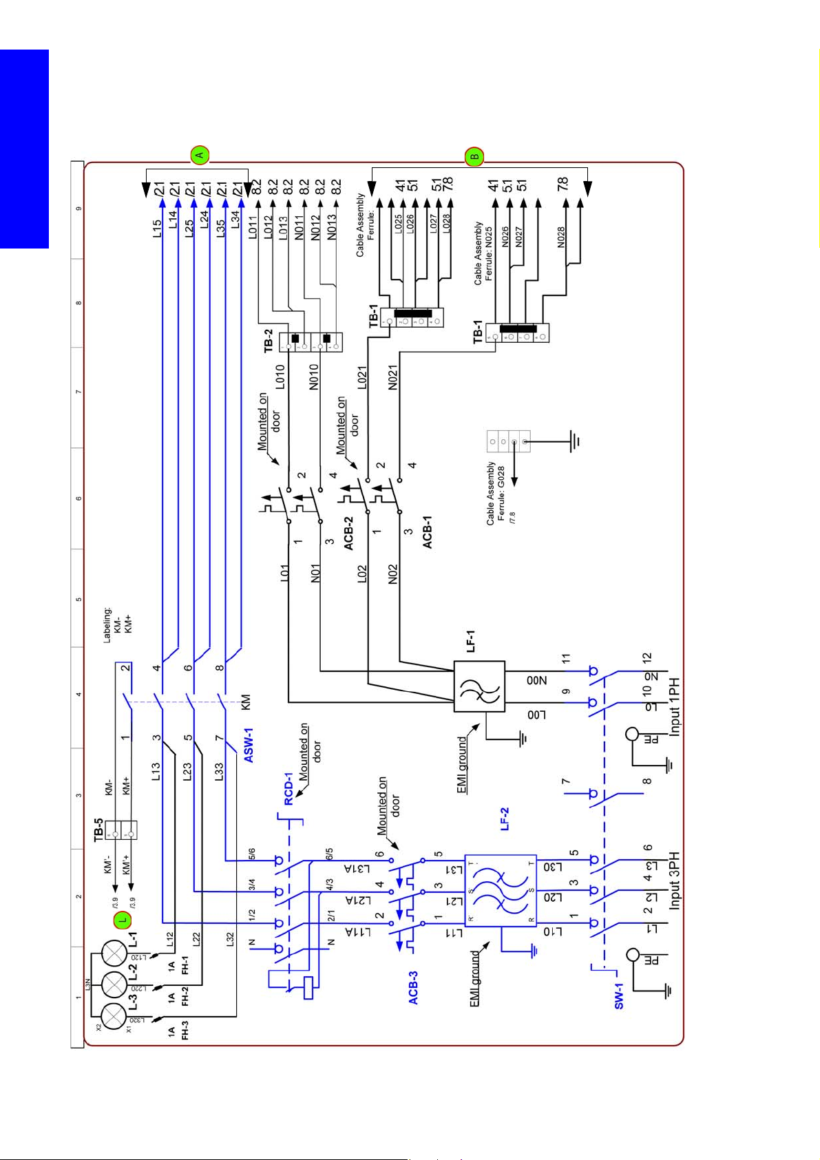
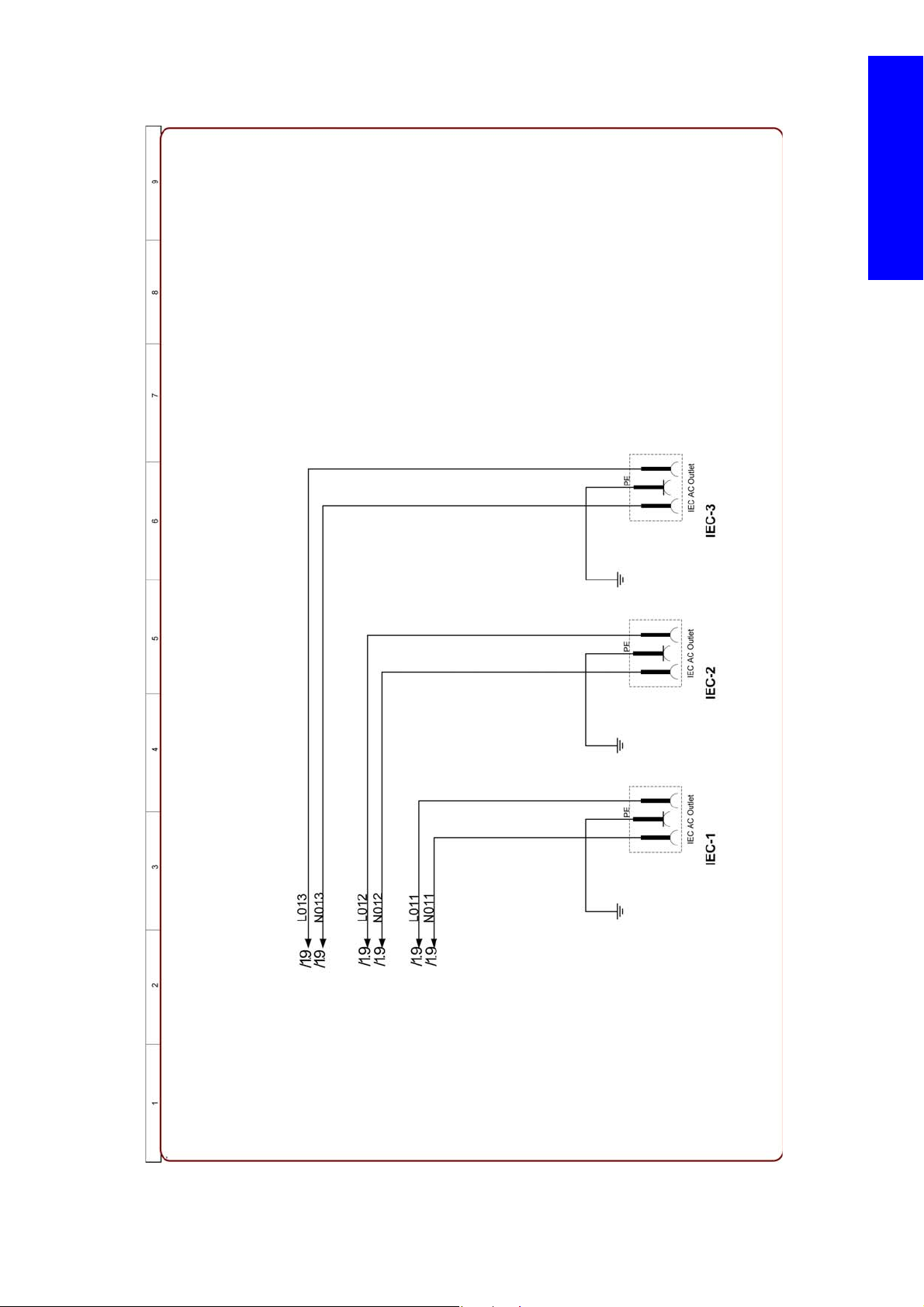
ECabinet Circuit Diagrams
Circuit Diagram 1: Power in distributing
Printer systems
10 Printer systems
Page 9
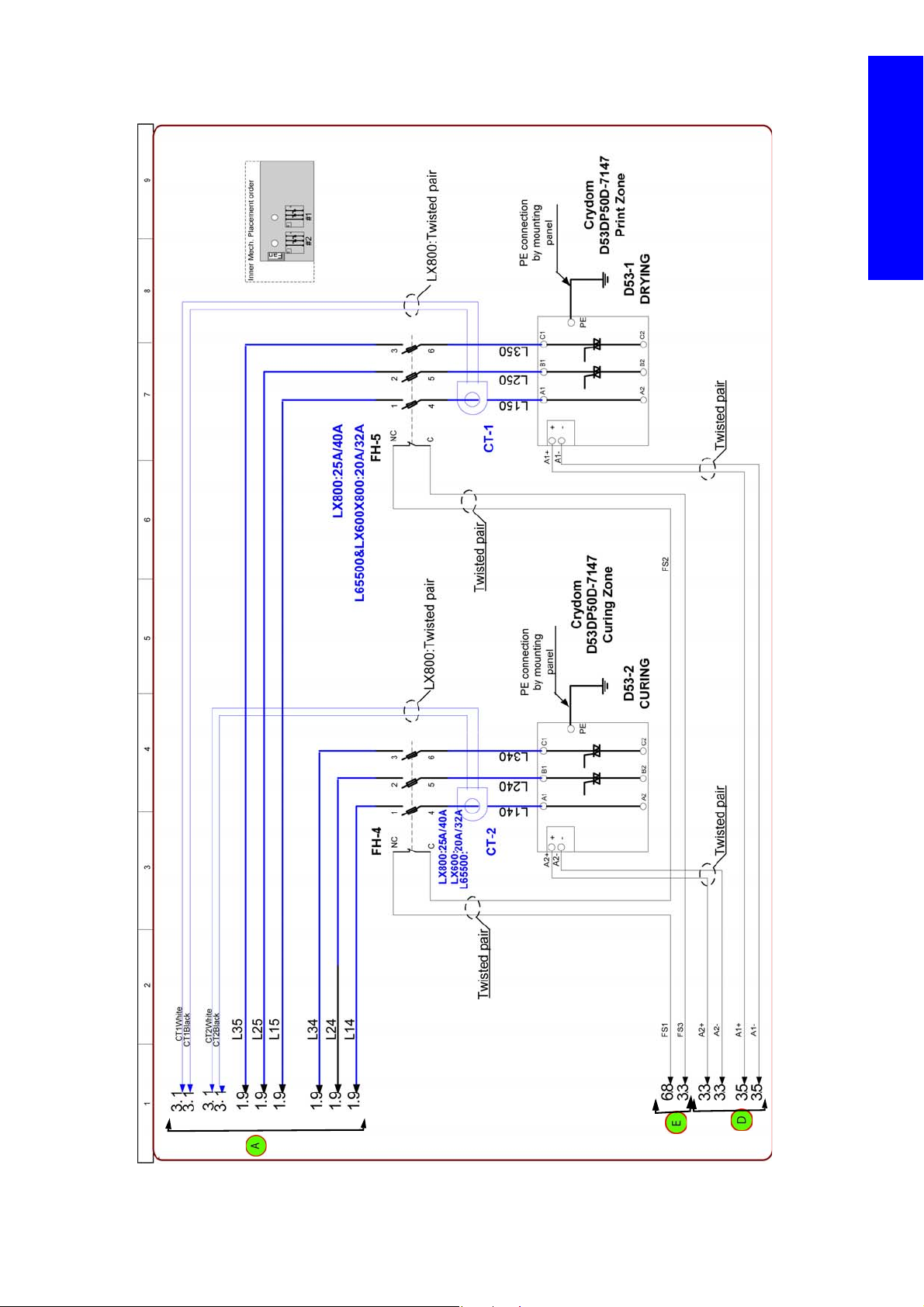
Circuit Diagram 2: Power modules, power control lines
Printer systems
Printer systems 11
Page 10
Circuit Diagram 3: Temperature Controllers
Printer systems
12 Printer systems
Page 11
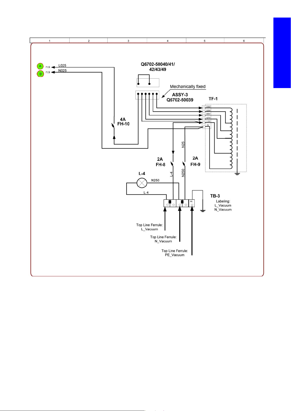
Circuit Diagram 4: Vacuum Transformer
Printer systems
Printer systems 13
Page 12
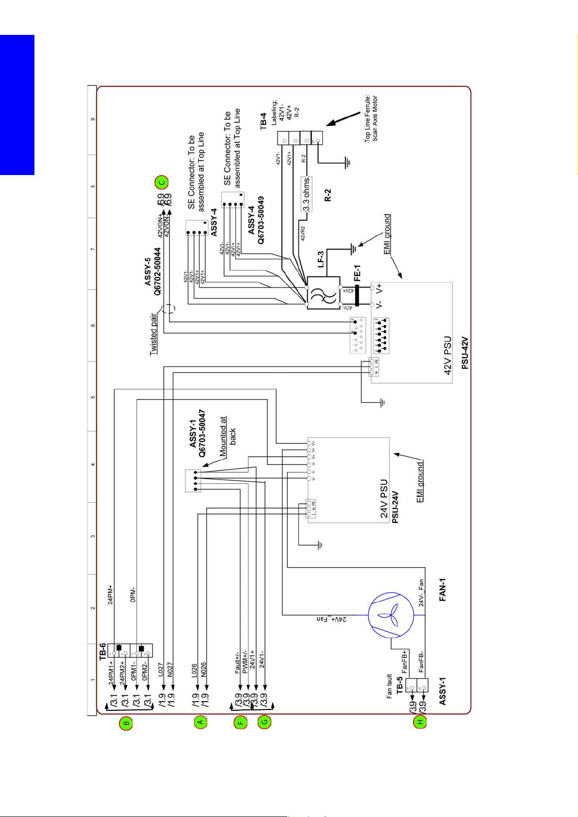
Circuit Diagram 5: Secondary Power Supplies and Internal Ecabinet Fan
Printer systems
14 Printer systems
Page 13
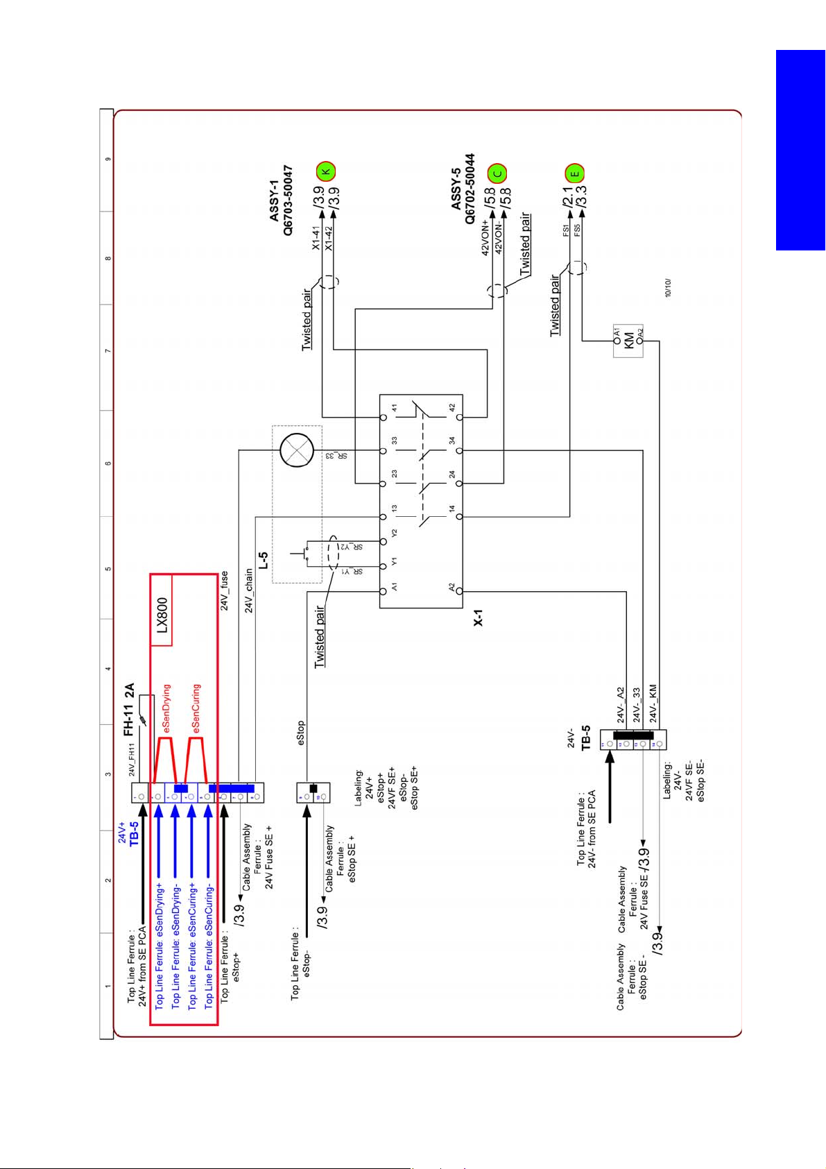
Circuit Diagram 6: Safety Control system
Printer systems
Printer systems 15
Page 14
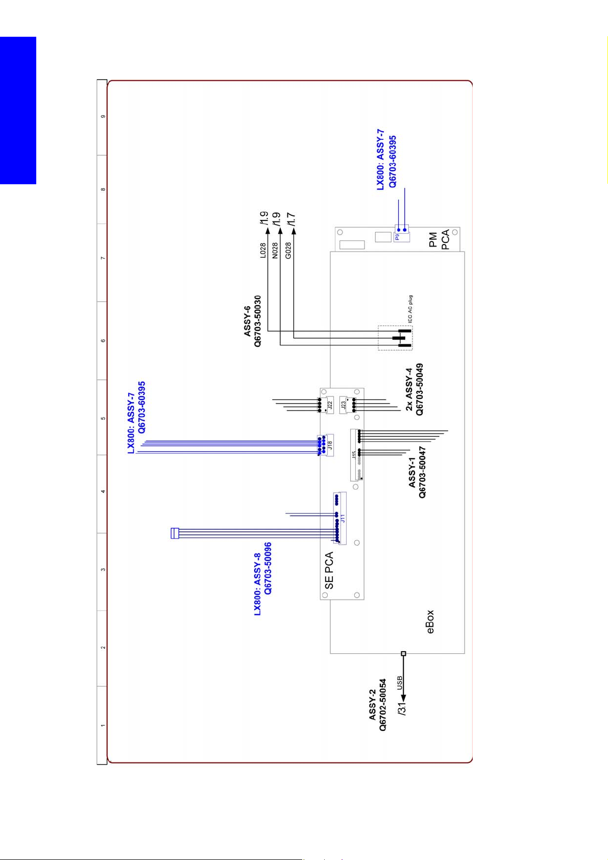
Circuit Diagram 7: Ebox Connections
Printer systems
16 Printer systems
Page 15
Circuit Diagram 8: PC Monitor Switch power connections
Printer systems
Printer systems 17
Page 16

Related tests, utilities, and calibrations
• Electrical cabinet diagnostic test Page 306.
Service parts
Printer systems
• Electrical Cabinet Page 451.
- Circuit Breaker
- Internal Fan
- Secondary Power Supplies
- Power Fuse Holder Block
- Safety Relay
- Scan Axis Brake Motor
- Vacuum Fan Power Transformer
- Main Power Switch
- Heating and Curing Temperature Sensor
- Power Fuses
- 3 Phase line filter
- Main Power Breaker
- Heating and Curing Power Module
-
Removal and installation
• Electrical Cabinet Page 522.
18 Printer systems
Page 17
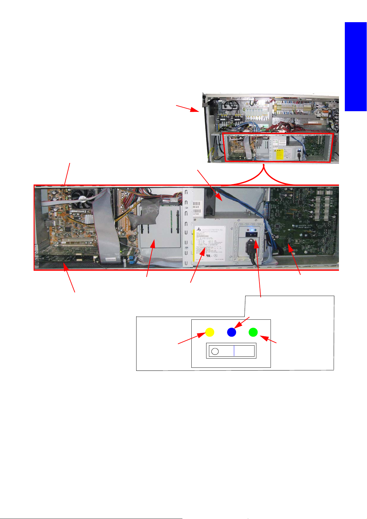
E-Box
Formatter PCA
Upper and Lower PCI PCA
Main Power Supply
ATX +24/42 PSU)
ECabinet
PrintMech PCA
ATX
On/Off switch
Hard Disk
1
Yellow led: Power
on>Stand by ON
Blue led: ATX On > Formatter
powered
Main Power Supply
Green led: 24/42
Printer On
The Ebox contains the main electrical control system in the printer. The e-box is the main processing and
control element of the machine where all main electronic units are comprised.
Components
The Ebox is inside the Ecabinet and contains the following components:
Printer systems
• Orange ON: System is powered (ACB 1 ON), System with Stand by power in the formatter waiting
• Blue ON: Formatter Power system (ATX) Active.Internal computer system running
• Green ON: 24/42V of the second part of the main power supply activated. These 24 Volts are the
for the Front Panel power ON button to be pressed to start up the system.
Check this led when the printer is not powering on by pressing the front panel button to ensure the
failure is not in the main power supply. If the led is Off AC power is not arriving to the main power
supply or Main power supply switch in the main power supply is off or the Main power supply is
faulty.
main source for the complete system to work. Without these 24 Volts the e-cabinet electrical system
will not work and the system will be impossible to be armed.
Printer systems 19
Page 18
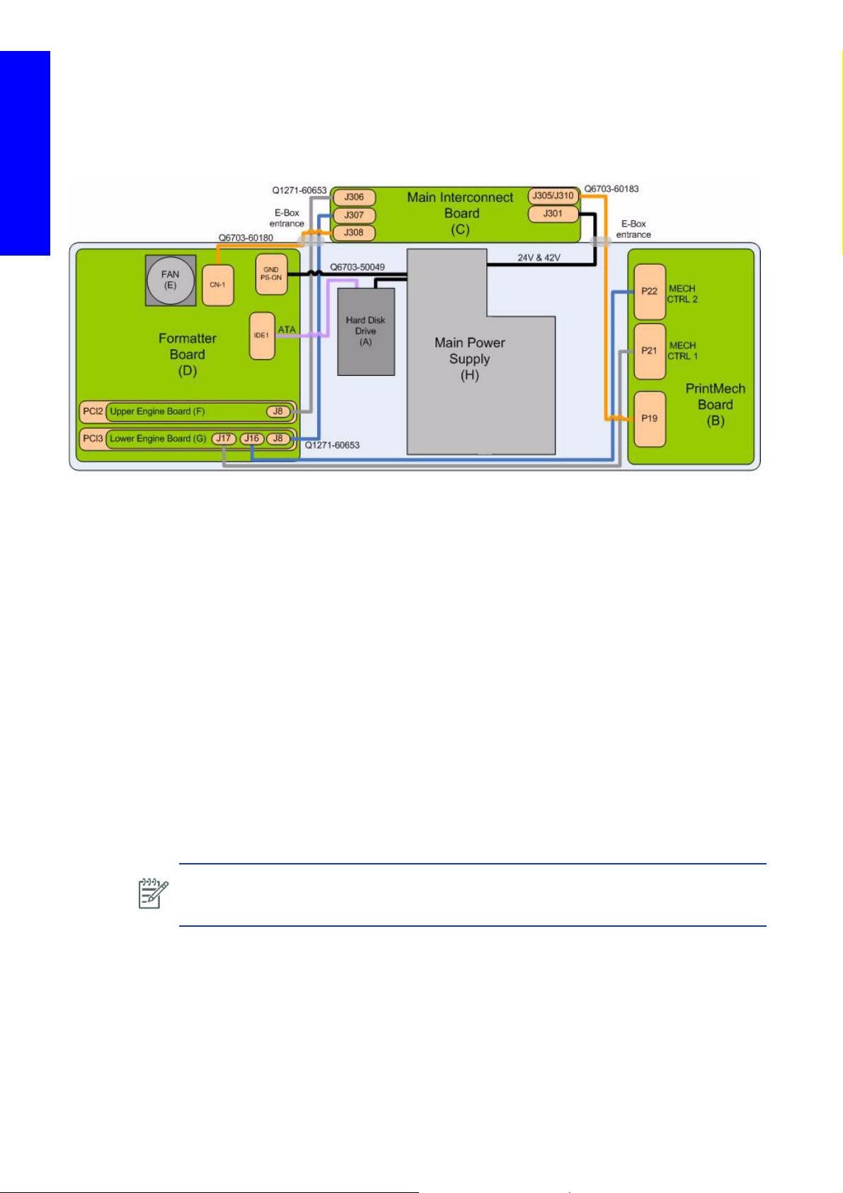
Functionality
The E-box contains the primary electrical systems of the printer in one area.
Circuit Diagram: PCAs in the Ebox
Printer systems
PCA Boards and connections
Components
Formatter PCA
The formatter is the motherboard of the printer, with an Intel microprocessor of 256 MB RAM memory
runs the operating system of the printer.
Hard disc drive
The HDD contains the main Firmware of the printer.
• The operating system is based on Montevista, an HP developed system.
• All calibration values, product number, serial number etc, are stored on the Hard Disc Drive. In
order to make sure that this information is not lost in the case of a failure of the HDD, a backup
is made:
- In the Main Interconnect Board for all the other information (other calibrations, total ink con-
sumption etc).
- In the ISM board for information related with the ISM area (calibrations of the ink sensors,
level of ink in the intermediate tanks, etc).
NOTE: In order to prevent the loss of calibration values, never replace the Hard disc system
and the ISS Main Board or the Hard disc system and the Main Interconnect Board at
the same time.
Upper and Lower Engine PCI Board
These two boards are the main controllers of the printer. They are responsible for all real-time
processing and are the ultimate controllers of all electromechanical systems.
The Lower Engine PCI Board controls all substrate path components (Drive Roller, Spindle Motors,
OMAS, etc.), and the link to the following controllers: Controllers of the PH cleaning roller (situated
on the main interconnect board). The one connected to the remote controller board controlling the
capping station movement motor. Both controllers are connected through the same bus (MICC).
20 Printer systems
Page 19
The Upper Engine PCI Board controls all non-substrate path components (carriage, scan axis motor,
scan beam height/PPS, PH cleaning assembly, service station, etc).
Printmech Board
The Printmech Board is mainly used to drive the four substrate advance motors.
• 2 Front Spindle motors (connected in series)
• 1 Rear Spindle motor.
• 1 Media advance motor (the drive roller motor)
NOTE: The motors are driven by 42V obtained from the secondary power supply which is
located inside the electrical cabinet.
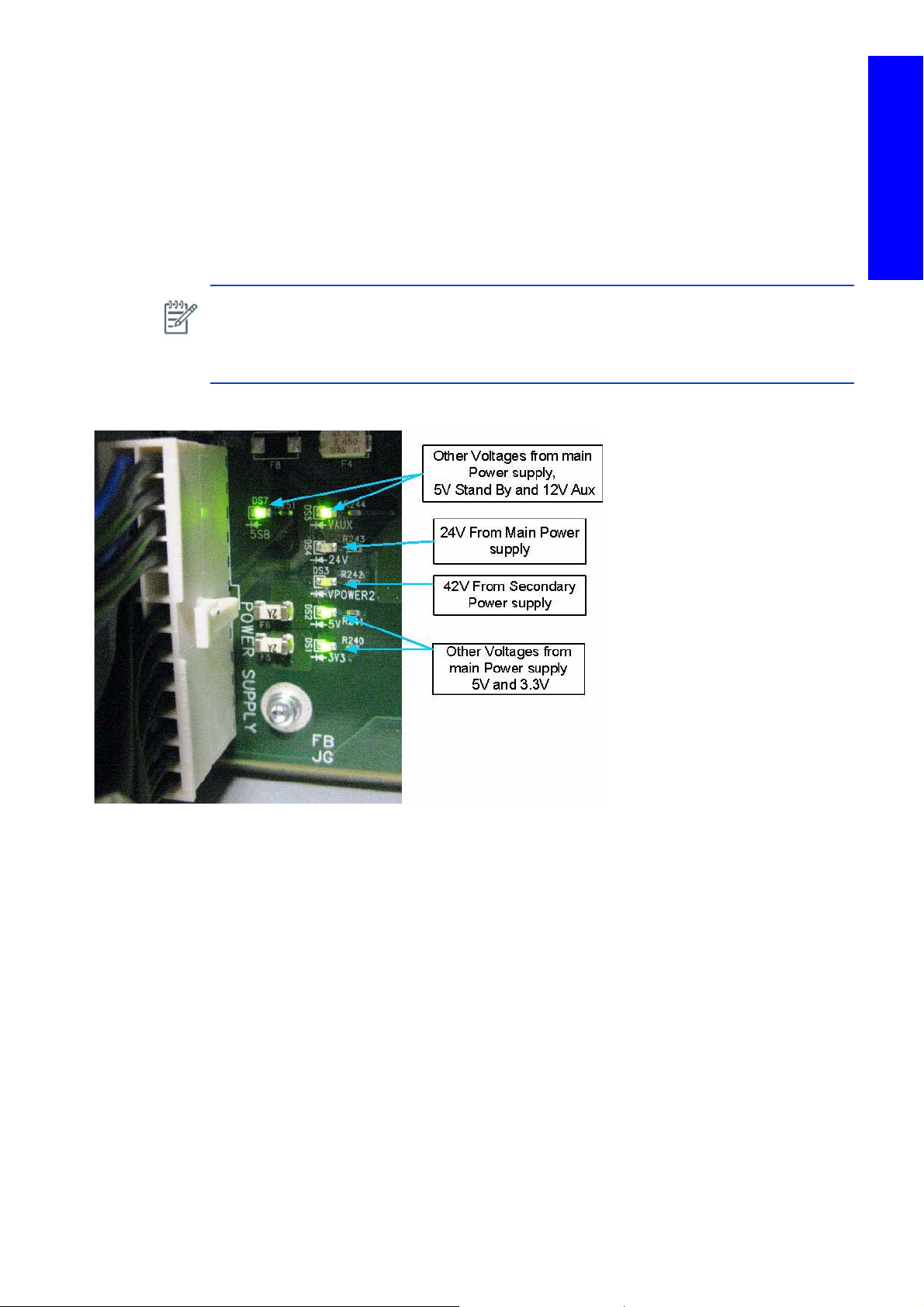
NOTE: To check that the 42V power supply arrives from the secondary power supply, see the
V Power 2 LED located on the Printmech Board.
Printmech leds
Printer systems
Printer systems 21
Page 20
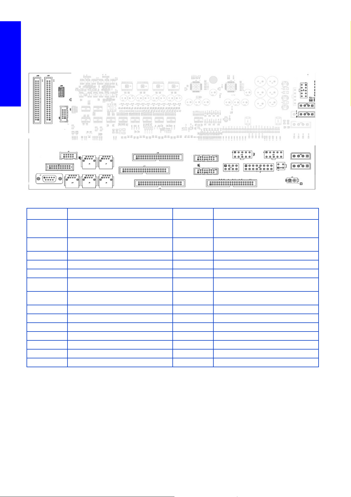
Main Interconnect Board connections
J306
J307
J3
J308
J4
J1
J27
J6
J8
J7
J5
J10
J12
J13
J26
J19
J22
J23
J15
J16
J17
J11
J310
J305
J301
J21
J20
J300
J18
Printer systems
Most of the signals to or from the electronics box pass through the interconnect board. All of the
cables connected to the Main Interconnect Board have labels indicating to which connection it
should be connected.
J Plug Description J Plug Description
J1 Scan Axis Motor data J16
J3 Drop Detector J17
J4 Front Panel J18 Roll to Free Floor Control/power
J5 Remote Control Board (Service Station) J19 Power 24v (E-Cabinet, PPS, ISS)
J6 Remote Control Board (PPS) J22, J23 From secondary power supply 42v
J10 Media Input (Rear Spindle System) J300
J7 ISM 1 (Ink system Module: data 1) J301
J8 ISM 2 (Ink system Module: data 2) J306 To upper engine PCI Board
J12 PH Cleaning System data (Encoders) J307 To lower engine PCI Board
J13 Front Right PPS (data) Encoder+switch J308 Front Panel Intermediate cable
J26 Rear Right PPS (data) Encoder+switch J305/J310 To Printmech 42v
J15 Ecabinet Faulty Signals J20 Power supply to Carriage 24v
J11 Media Output (Front spindle system Encoder) J21 Power supply to Carriage 42v
J27 OMAS/Vacuum control data
Power& Control for PPS rear right motor PH
Cleaning Roller motors & Capping Station 24v
power to remote controller
Power & Motor control for PPS front right motor &
vacuum controller (24v & 5v)
Encoder readers from the Printhead cleaning
Rollers to the Upper Engine PCI board
42v from secondary 42 v power supply to
PrintMech
22 Printer systems
Page 21
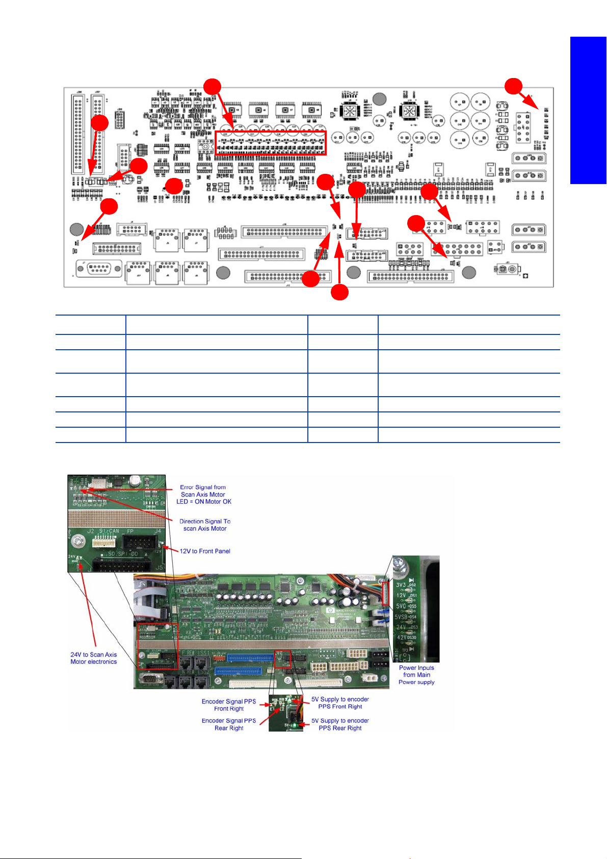
Main Interconnect Board LEDs
2
1
3
4
5
6
8
7
9
10
11
12
Number Description Number Description
1 24 LEDs (DS6 to DS29) 7 From PPS encoder (rear, right)(DS36)
2
3Not used 9
4 Power temperature sensor 10 24v to Scan Axis motor (DS40)
5 5v for the PPS encoder (rear, right)(DS41) 11 Scan Axis motor comms signal (DS32-33)
6 5v for the PPS encoder (front, right)(DS37) 12 From Scan Axis Motor (DS34)
ATX from Main Power Supply+12v, +5 (including
5v stand-by)
8 From PPS encoder (front, right) (DS35)
12v from main power supply going to Front
Panel (DS39)
Printer systems
Photo detail of Main Interconnect
Printer systems 23
Page 22
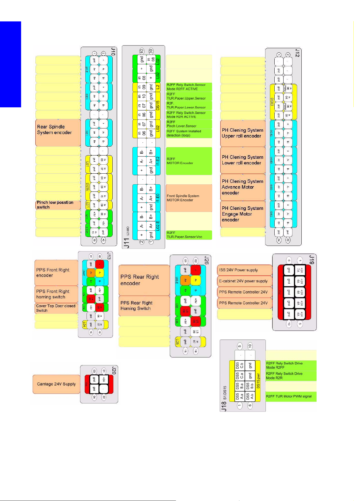
Pin outs of the Main Interconnect
Printer systems
24 Printer systems
Page 23
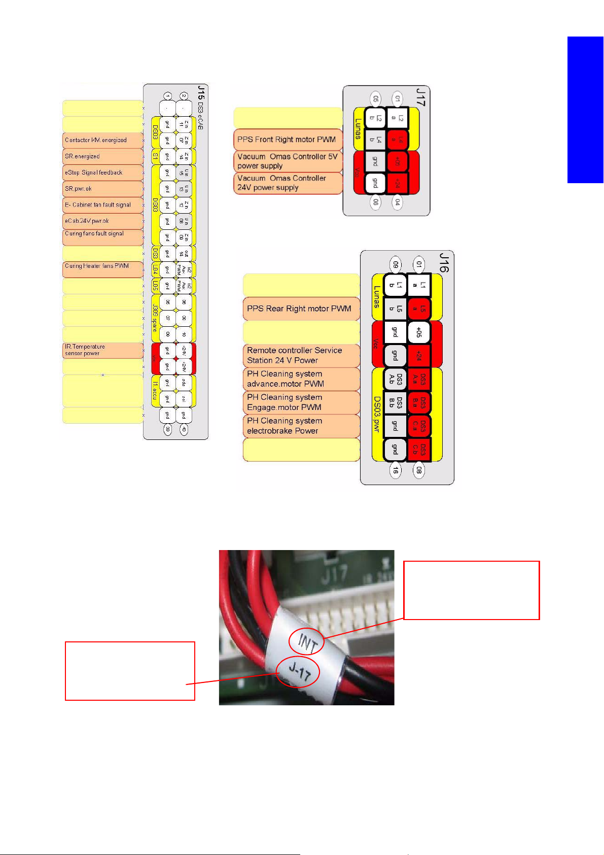
Pin outs of the Main Interconnect
The’ J17’ on the label
identifies the J17 connector
on the Main Interconnect
Board.
The ‘INT’ on the label
signifies Main INTerconnect
Board, which this cable is
connected to
Printer systems
Labels on the cables
Labels are attached to the cables to identify where the cables go to, and in some cases identify the
functionality of the cable.
Printer systems 25
Page 24

Label abbreviations
Related part Abbreviation on label
Switch SW
Encoder ENC
Printer systems
Power PWR
Lan LAN
Cover CV
Main Interconnect Board INT
Engine upper PCI board ENG 0
Engine lower PCI board ENG 1
PrintMech board PM
Hard Disk Drive HDD
Main Power Supply PWR
Powe r Cabinet PWR CAB
Secondary 24V Power supply PWR CAB SEC 24V
Secondary 42V Power supply PWR CAB SEC 42V
E-cabinet 24V intermediate connection PWR CAB 24V Out
IR temperature Sensor - Left (Curing) SAX TS - LEFT
CUR IR temperature Sensor - Right SAX TS - RIGHT PZ - H
Print zone lamps power SAX PZ - H PWR
Curing lamps power SAX CURING PWR
Curing fans CURING FANS
Front Spindle Motor FSM - T/B ( Top/Botto m)
Rear Spindle Motor RSM
Drive Roller Motor MA (media advance)
Carriage Lid Switch C Lid SW
Printhead Board C PH1/2/3
Note: SAX=Scan Axis
L65500/LX600 Power lines specifications: 3 phase line
High Voltage system Low voltage systems
Input voltage 3 x 380-415V~ (-10%+6%) 3 x 200-220V~ (-10%)
Circuit Breaker 20A 32A
Input frequency 50Hz 60Hz
Power consumption 12kW 12kW
maximum load current (per phase) 32A 32A
L65500/LX600 Power lines specifications: Single phase line
High Voltage system Low voltage systems
Input voltage (phase to neutral) 3 x 220-240V~ (-10%+6%) 115-127 V~ (-10%) (Japan 200 V~)
Input frequency 50Hz 60Hz
26 Printer systems
Page 25

High Voltage system Low voltage systems
Power consumption 1kW 1kW
maximum load current (per phase) 10A 10A
LX800 Power lines specifications: 3 phase line
High Voltage system Low voltage systems
Input voltage (line to line) 3 x 380-415V~ (-10%+6%) 3 x 200-220V~ (-10%)
Input frequency 50Hz 60Hz
Power consumption 15kW 15kW
maximum load current (per phase) 30A 50A
LX800 Power lines specifications: Single phase line
High Voltage system Low voltage systems
Input voltage (line to line) 200-240V~ (-10%+6%) 115-127 V~ (-10%) (Japan 200 V~)
Input frequency 50Hz 60Hz
Power Consumption 1kW 1kW
Maximum load current (per phases) 10A 10A
Related tests, utilities, and calibrations
• From diagnostic mode: Electronics Page 291.
• Service Utilities: Electrical system Page 291.
Service parts
• Electrical Cabinet Page 451.
Printer systems
Removal and installation
Electronics Page 509.
Printer systems 27
Page 26
Substrate path
Drive Roller Encoder disc
Drive Roller Motor Assembly
Pinch mechanism
Drive Roller
Rear Spindle
Drive
Roller
Encoder
sensor
The media roll is mounted on the rear spindle and is collected on the front spindle. Media goes from the rear
spindle over the drive roller, over the print platen, over the diverter and onto the front spindle.
Each of the spindles has its own motor system. Vacuum is applied at the level of the print platen to keep the
substrate flat.
Printer systems
Components
The advance of the media is applied by the motor of the drive roller. There is a pinch mechanism to prevent
the substrate slipping against the drive roller.
The accuracy of the substrate advance is controlled with two components:
• The Driver Roller Encoder disc.
• The OMAS: This is an optical sensor which works like a camera taking pictures of the media’s fibre,
the pictures are then compared, measuring actual distances during movements in order to apply
small corrections in the advancement of the substrate.
28 Printer systems
Page 27

LX800: Roll to Free Fall Assembly functionality
OMAS Sensor Assembly
Diverter Assembly
Vacuum unit
Side plate Spindle Assembly
OMAS Vacuum Connector
This is a feature which comes with the LX800, it provides the user a method to be able to collect media
and cut it as the printer prints dynamically.
Printer systems
In addition to the Roll to Free Fall there is also a Media Collector (front spindle). The added functionality
can be activated on demand by the user.
Printer systems 29
Page 28

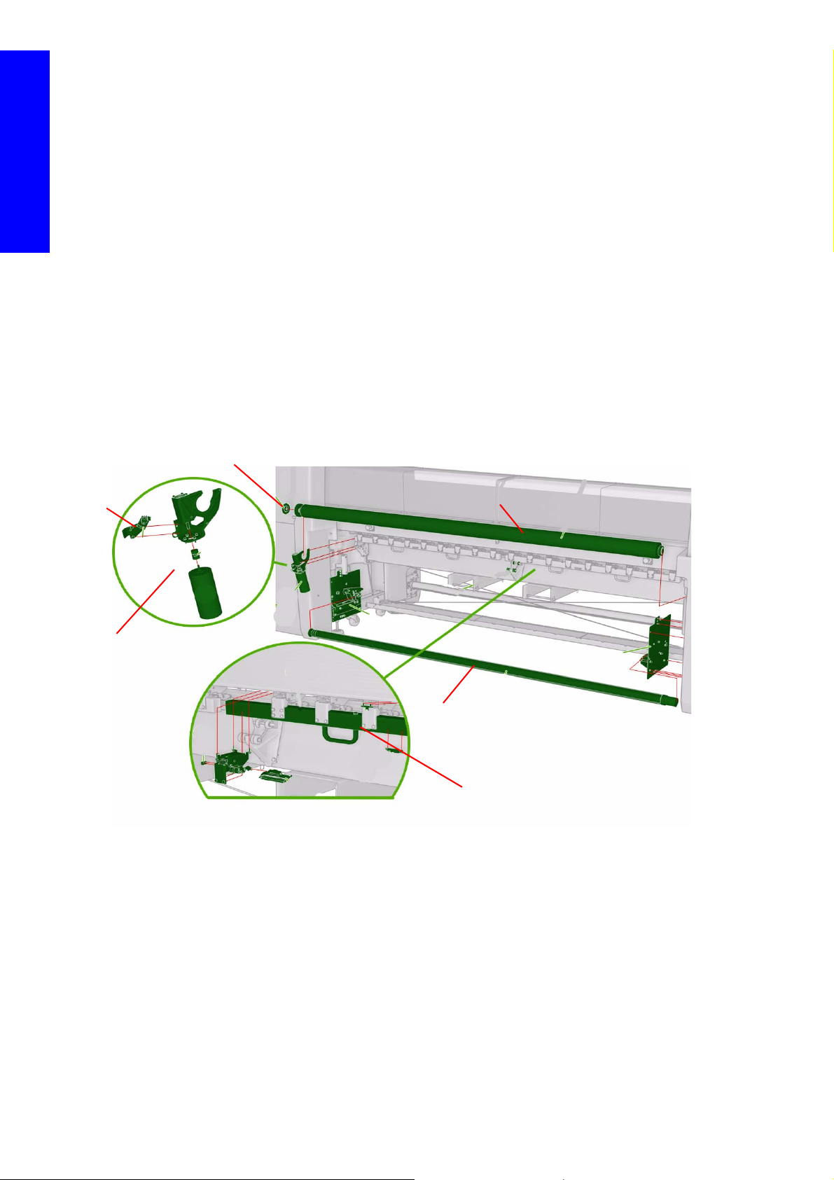
LX800: Roll to Free Fall Assembly mechanical system
The Roll to Free Fall assembly is located on the front of the printer between the Diverter and the Front
Spindle assembly. The whole assembly is held in place by left and right plates, secured to the structure of
the legs.
Printer systems
The drive plate of the Roll to Free Fall is located on the right side of the printer and
operates in an analogue system to the Front Spindle with a drive motor and encoder
system. The motor transmits the torque directly to the roll to Free Fall roller via a
transmission belt.
Dual Roll Functionality
The dual roll enables the printer to print on two different rolls of substrate at the same
time, significantly improving the productivity of the printer.
30 Printer systems
Page 29

A differential mechanical system is used to keep the same tension in both rolls of media mounted on the
Core supported by the end hubs
Media Core
Differential gears
Point of attachment
of transmission bar with
differential
which are suspended on the
ball bearings
Media Core
Core held on to
by the rubber system,
the end hubs
Transmission Bar
Gear
Gear
Gear
where the torque is transmitted from
the differential
transmission bar by
End Hub
1. Dual Roll Gear (Differential)
2. Dual Roll Tool and Screw Pro-
tection kit
3. Dual Roll End Hub
4. Dual Roll Spindle 104
5. Dual Roll Rubber Kits
7. Dual Roll Cap Left
8. Dual Roll Cap Right
same spindle, regardless of the type of media or diameter of each roll. The gear connection allows
movement until torque on the both sides is the same. This allows the usage of different diameters of media
rolls.
Printer systems
The left core is linked to the right core via the differential. The whole assembly is mounted on the spindle
via ball bearings, this enables the assembly to turn on the spindle easily, but at different rates, while
maintaining the same tension between the left and right sides.
Pinch Mechanism
The Roll to Free Fall beam holds an array of pinches. All the pinches are interlinked by a bar, which
Printer systems 31
transmits any open or closing movement from the Pinchwheel lever, to all the pinches. Underneath the
Page 30

pinchwheel system is a sensor which detects the open and close state of the pinches. The system contains
Pinchwheel switch
Shock absorber
a shock absorber system which prevents damage to the printer and/or the media.
Printer systems
NOTE: There are two types of Pinchwheel mechanism: 18 inner and 2 outer types. The two
outer pinchwheels act as reference points of the system.
Media collector
On the front right hand side, underneath the Roll to Floor main beam is the media collector system. The
system comprises of two sensor and a PCA in an enclosed U shaped structure. A cosmetic cover is secured
over the whole system as further protection.
32 Printer systems
Page 31

Media Collector sensors
The sensors are two distance detecting sensors which create a beam of infrared light on the media to sense
the upper and lower position of the paper. The system will operate the collector motor (front spindle system)
to keep the bottom area of the media loop within the area defined by the sensors.
The Loop shaper
The loop shaper is part of the media collection system and gives shape to the loop of media that hangs
down from the media paper path, it also gives added tension to the media as its being collected. The length
of the loop shaper can be changed by removing and/or adding sections to it in order to work with various
widths of media.
Drive Roller Assembly
The driver roller system contains the following:
Printer systems
• Roller
• Pinch Wheels
• Motor
• Encoder Disc
• Encoder PCA
The Drive Roller system advances the substrate under control. The Encoder Disc and Encoder PCA
provide feedback on the advance of the substrate. The Pinch Wheels ensure that the substrate does
not slip and moves the same distance. There are separated into two modules that are manually
opened and closed while loading the substrate.
Diverter
The Diverter Assembly makes sure that the substrate exits the substrate path correctly, and prevent
the substrate from becoming damaged.
The OMAS
The OMAS consists of an optical sensor is located
underneath the print platen. It has a dedicated controller
board, which is connected to the Main Control board
through a CAN bus.
The optical sensor takes pictures of the back of the substrate
as it moves across the platen. These pictures evaluate the
precision of the substrate movement. The evaluations result
in a set of values that describe the substrate advance error.
The values obtained are then used to feed the substrate into
the printer, correcting the movement, and making on-going precision adjustments that avoid any
possible substrate skew.
The OMAS temperature sensor detects the heat around the OMAS sensor, which comes from the
Heating and curing system, the system can then make small adjustments to compensate.
The Vacuum system
Printer systems 33
Page 32

The vacuum is used to keep the substrate flat on the print platen. There are different Vacuum levels
Vacuum
sensor
Drive roller
Rear spindle
Diverter
Front spindle
Vacuum
Pinchwheels
Drive roller
Diverter
Front spindle
Vacuum
Pinchwheels
depending on the substrate used. The level of vacuum is determine automatically during the loading
of the media.
The vacuum pump is a 110V pump. It receives power from a transformer in the power cabinet. This
transformer need to be configured according the input voltage during the installation. The amount
of Vacuum is measured by a sensor. The sensor is located in the vacuum controller PCA.
Printer systems
Functionality
Substrate path workflow overview LX600, L65500 & LX800 (Roll to Roll)
The following steps describe the substrate path workflow.
1. The substrate passes from the rear spindle, over the drive roller (and under the pinches), over the diverter,
and is collected on the front spindle.
2. The rear spindle system maintains tension on the media.
3. The drive roller’s motor advances the substrate. The substrate is pressed against the drive roller by the
pinchwheels, to ensure a correct substrate advance.
34 Printer systems
Page 33

4. The Print Platen is designed for minimal resistance against the substrate’s advance, and includes suc-
Diverter
Front spindle
Vacuum
Drive roller
Rear spindle
Diverter
Front spindle
Vacuum
OMAS sensor
Pinchwheels
Diverter
Front spindle
Vacuum
Diverter
Front spindle
tion holes for the vacuum.
5. The substrate passes over the OMAS sensor which is able to detect very small errors in the advance-
ment of the media. These advancement errors are communicated to the motors on the drive rollers and
very small correction adjustments are applied to the movement of the substrate.
Printer systems
NOTE: The OMAS sensor camera cannot see the fibers on some substrates, such as
transparent media or very dark substrates. In these cases, the OMAS sensor can be
disabled. To disable the OMAS sensor
6. The Vacuum level is set according to the substrate type and print options, it sucks the substrate to the
print platen, making sure that the substrate is flat.
7. The substrate exits the print zone and passes over the passive diverter (no motor), this enables the sub-
strate exit correctly, undamaged, friction is reduced and controlled.
See page 404.
Printer systems 35
Page 34

8. The front spindle has two motors that pull the substrate through the print path to maintain tension and
Front spindle
Substrate collector
Pinches
Roll to Free Fall
Substrate collector
Pinches
Roll to Free Fall
to roll up the printed image.
Printer systems
9. LX800 only:
a. Roll to Free Fall: The pinches & Roll to Free Fall Roller keep the paper in tension while the
end of the paper is free to pass over the Substrate Collector and fall to the floor, or be cut as
the printer prints.
b. Substrate Collector: The pinches & Roll to Free Fall Roller keep the paper in tension while
the substrate collector rolls up the printed media as it prints.
Related tests, utilities, and calibrations
• Diagnostic mode
• 2.3 Substrate path diagnostic test: Page 418 .
• 3.2 Front spindle diagnostic test: Page 307.
• 3.3 Rear spindle diagnostic test: Page 31 0 .
• 3.4 Drive roller diagnostic test: Page 312 .
• 3.5 Pinch switches diagnostic test: Page 313 .
• Service utilities
• 1.3.1 Turn drive roller service utility: Page 402.
• 1.3.3 Enable/disable OMAS service utility: Page 404.
• 1.3.2 Enable/disable SCAPA service utility: Page 403.
• 1.5 Scan axis check: Page 408.
• 4.3.2 OMAS calibration: Page 426.
Service parts
• Front Substrate Path (1of 2) Page 454.
36 Printer systems
Page 35

• Front Substrate Path (2 of 2) Page 455.
Refer to following
photo
• Rear Substrate Path Page 456.
• Rear Substrate Path Page 457.
• Dual Roll Assembly Page 458.
• Roll to Floor Page 459.
Removal and installation
• Substrate Path: Page 547.
Substrate Path Circuit Diagram
Printer systems
Printer systems 37
Page 36

Vacuum Controller Connectors
2 motors of the Roll to Roll (or Collector)
To set & control the status of the relays
Motor of the Roll to Free Floor
Part detecting the substrate loop position
1
2
3
1. Cable detection, a way for the printer to check that the cable is correctly connected, if it is not a system error will display.
2. From the encoder reader placed at the back of the Roll to Free floor motor
3. The lever switch of the Tension Roller, detects if it is raised of lowered.
Printer systems
LX800: roll to Free Floor and Media Collection Electrical system
38 Printer systems
Page 37

Ink System
The ink system is located in the left compartment of the printer (inside the left covers) and delivers a
continuous supply of ink to the printheads. It can detect an ink leakage anywhere in the system, including
inside an Ink Cartridge. It also tracks and determines when an Ink cartridge needs replacing.
In addition the system is designed to allow Ink Cartridge replacement while printing (Hot Swap
functionality)
Components
• Ink Cartridges
• Printheads.
• TRS
• The twelve Intermediate ink tanks (two for each color), located at the bottom front and rear of
the ink system compartment.
• The ISM Air Circuit Module, located on the first tray from the top, provides the air pressure
needed to pressurize the intermediate ink tanks and send ink to the printheads.
• The two Air Pressure Bottles prevent cross contamination of ink when a broken bag occurs
inside an intermediate ink tank. It also works as cushion device for the air pressurization system
• The ISM Ink Circuit Module, located on the lower tray, manages the flow of ink using a complex
set of valves.
• There are two Ink sensors boards, each with three ink pressure sensors. Each board comes
calibrated from the factory with unique values. New service parts require a service procedure to
manually enter in calibration values. Ink Pressure Sensor Calibration:
• The Ink Cartridge Connector Set connects to the ink system to the ink cartridges. The ink
connectors include read the acumen data from the cartridges, and also an internal switch to detect
whether or not the connector is correctly inserted.
• The ISS Main Board controls the entire ink system.
Printer systems
Page 339.
Functionality
Ink supply hot swap
• The printer allows the user to change the Ink Cartridge while the printer is printing, as it is actually
using the ink stored in the intermediate tanks.
Printer systems 39
Page 38

Intermediate tank set swap
Ink Pressure Sensor
Higher column of ink
= higher pressure
Lower column of ink
= lower pressure
• While one of the Intermediate tanks is refilling, the other intermediate tank is pressurized to enable
the correct ink flow to the printheads.
• Once the quantity of ink falls below a certain threshold, the printer calculates the amount of ink fired
from the printheads and resupply the intermediate tank with ink, while at the same time swapping
the amount of pressurization supplying ink from the other set of intermediate tanks.
Printer systems
Low ink carriage detection
Control of ink to the Intermediate Tanks
Intermediate tank set swap
• While one of the Intermediate tanks is refilling, the other intermediate tank is pressurized to enable
• Once the quantity of ink falls below a certain threshold, the printer calculates the amount of ink fired
The pressure sensor detects the amount of pressure of the column of ink above. When the column is
low (empty cartridge), the sensor triggers the empty condition. The pressure of a fluid mainly
depends on the height of the column of fluid.
Once the main electrovalves open the ink falls into the intermediate tanks by gravity. When an
intermediate tank is full, the ink flows stops, which generates a pressure difference which is detected
by the pressure sensor.
the correct ink flow to the printheads.
from the printheads and resupply the intermediate tank with ink, while at the same time swapping
the amount of pressurization supplying ink from the other set of intermediate tanks.
Air System Functionality: The Intermediate tanks push the ink to the printheads
The system has two air pumps for each set of intermediate ink tanks (four total). The air pressure is distributed
using an air pressure bottle (one for each tank set) with air tubes going out to the tanks.
Each tank has a bag inside which holds the ink. In order to send the ink to the printheads, the air pumps push
air into the enclosed space of the tanks around the bags to pressurize them and force ink out.
40 Printer systems
Page 39

While one tank sends ink to the printheads, the other is being refilled. In this way, continuous printing is
Air Circuit
Printhead
Intermediate Tank
Ink Circuit
Air Pump
Air Pressure
Sensor (in
ISM board)
Relief valve
Air pumps
Air Pressure
bottle
Relief valve
Broken bag in
intermediate
tank
Intermediate ink
tanks
Air Pressure
sensor
possible while changing ink cartridges.
•Air pressure is constantly
monitored by an Air Pressure
Sensor located on the ISS PCA
•The system is able to
depressurize with the relief valve
located in the Air System.
Broken bag in an Intermediate Tank
In the event of a broken bag in an
intermediate ink tank, the ink
system uses the air pressure bottle
to prevent cross contamination of
inks.
Printer systems
When a broken bag is detected by the sensor located inside the intermediate ink tank, the relief valve opens
to release the air pressure of the system. The ink going through into the air system can at maximum flow and
fall into the bottom of the bottle, preventing cross contamination of colors.
Printer systems 41
Page 40

Ink Cartridge LEDs Indicators
• Red: Connector connected to the cartridge, but communication issue with the
• Yellow blinking: Ink Cartridge empty
• Green blinking: Filling intermediate ink tank or reading acumen. Do not
Printer systems
• Green: Functioning correctly, no issue
• No LED: Connector not connected
Acumen. Cannot use
disconnect!
the cartridge.
Related tests, utilities, and calibrations
• Diagnostic mode
• 4.1 ISS Electronics diagnostic test: Page 318 .
• 4.2 Air Pressure System diagnostic test: Page 319 .
• 4.3 Ink Supply Connector diagnostic test: Page 320.
• 4.4 Broken bag recovery: Page 321.
• 4.5 Ink System Leakage diagnostic test: Page 322.
• 4.6 ISS Electrovalves diagnostic test. Page 323.
• 4.7 Recover ink leakage: Page 324.
• 4.9 Intermediate tank change: Page 324.
• 4.10 Ink cartridge LEDs diagnostic test: Page 326.
• 4.11 Ink Pressure Sensors calibration: Page 326.
• 4.12 Ink pressure at Pen: Page 328.
• 4.13 Force Filling Tanks: Page 330.
• 4.14 No flow Error recovery: Page 330.
• 4.15 ISS Test components Menu: Page 331.
• 4.16 Flushing Menu: Page 335.
• 4.17 Intermediate Tank Ink Life Cycles: Page 337.
• 4.18 Intermediate Tank Ink Amount: Page 337.
• 4.19 Intermediate Tank Refill Time: Page 338.
• 4.20 check Ink Supplies: Page 339.
Service parts
• Ink System: Page 460
Removal and installation
• Ink system: Page 598
42 Printer systems
Page 41

Ink System Circuit Diagram
Printer systems
Further information about the two 'LAN' cables linking the ISS board to the main interconnect:
• The cable linking J36 (ISS board) to J8 (Main Interconnect) contain the specific bus to communicate
with the cartridge ACUMEN and one specific interruption line (the line is activated for some events,
such as when a connector of a cartridge is disconnected or connected back). All the signals are
moved down to the upper engine PCI board.
• The cable linking J37 (ISS board) to J7 Main Interconnect) mainly contain lines of an 'I2C' bus, that
the printer can get the detailed status from the main elements of the ISS area (Ink Pressure Sensor,
Air Pressure Sensor, Broken Bag, ...) and can also set the main elements of the ISS area (Air Pump,
Ink Electrovalves, ...)
Printer systems 43
Page 42

ISS PCA with leds and connectors
Printer systems
44 Printer systems
Page 43

Scan Axis
carriage
Belt Tensioner
Scan Axis motor
Scan Axis Belt
The Scan Axis system can be separated into three different subsystems:
• Scan Axis: Carriage Impelling System (Carriage Movement)
• Scan Axis: PPS System (Print to Paper Space)
• Scan Axis: Service Station (Capping)
Scan Axis Impelling System
The Scan Axis Impelling System is designed to move the Carriage Assembly across the scan axis under
control, for the purpose of printing and moving the printheads into a position where they can be serviced/
maintained.
Components
Scan Axis Motor
The Scan Axis Motor, located on the right side of the printer, drives the belt that moves the carriage.
Scan Axis Impelling Belt
The Scan Axis Belt is connected to the carriage on both sides, and runs from the Scan Axis Motor to
the Scan Axis Belt Tensioner. The motor drives the belt, which in turn moves the carriage back and
forth.
Printer systems
Scan Axis Belt Tensioner
Scan Axis Encoder Strip and Encoder Sensor
Carriage Chain Assembly (TRS system)
Functionality
Carriage movement
The Scan Axis Belt Tensioner, located on the left side of the printer, acts as a pulley for the Scan Axis
Impelling Belt opposite the motor. Two springs mounted between the pulley and scan axis sideplate
maintain tension on the belt.
The Scan Axis Encoder Strip is a metal strip running the length of the scan axis. As the carriage is
moved back and forth by the Scan Axis Impelling System, an encoder sensor mounted on the carriage reads the encoder to determine the speed and position of the carriage. This feedback is then
used to control the Scan Axis Motor movements
The Carriage Chain Assembly contains the ink tubes and trailing cables that connect to the carriage,
it is designed using a ‘chain system’ that enables the Carriage Chain Assembly to bend while the
carriage moves back and forth. The chain system also protects the ink tubes and data lines housed
inside.
A belt is attached to each side of the carriage. The belt is driven by the scan axis motor mounted on
the right side of the printer. On the left side of the printer, the scan axis belt tensioner acts as a pulley
for the belt which uses a simple spring mechanism to maintain tension on the belt.
Printer systems 45
Page 44

Tension of the belt
Left side (outside)
Left side (inside)
Springs exert a force against the belt
maintaining tension
A screw on the other side of the wall enables the
belt to be adjusted or tension released for removal.
Printer systems
Force is applied to the belt via springs on the left side of the printer.
To ensure the correct tension of the belt, make sure the side face the tensioner is located between
the two marks located on the tension poles
Related tests, utilities, and calibrations
• 5.1 Impelling system diagnostic test: Page 339.
• Move the position of the carriage.
- 5.2.1 Move to home position: Page 342.
- 5.2.2 Move to load position: Page 343.
- 5.2.3 Move to Printing position: Page 344.
• 1.5.1 SAX Friction analysis. Page 408.
Service parts
• Scan Axis (A): Page 463
Removal and installation
• Scan Axis Impelling System: Page 619 .
46 Printer systems
Page 45

Scan Axis Impelling System Circuit Diagram
Pin 1
Pin 4
Pin 3
Pin 2
Pin 4: Earth
Pin 1: +42V
Pin 2: Resistor cable
Pin 3: GND
Printer systems
Identify the pins of the power cables from the Scan Axis motor.
Printer systems 47
Page 46

The pins shown above go to the location on the fuse block in the E-Cabinet (after having identified them
Capping post
Capping Module bottom
Capping Module top
Rubber cap
Springs
Capping
Module base
with an multimeter):
• Pin 1 connects to TB4-2
• Pins 2 connects to TB4-3
• Pin 3 connects to TB4-1
• Pin 4 connects to Earth
Printer systems
Scan Axis Service Station (capping and drop detection)
The Capping of the printheads is performed in the Service Station, the process seals them while they are not
in use, to keep the printhead’s nozzles in good condition while the printer is not printing. The assembly is
located on the right side of the printer, beneath the carriage path. The Service Station also contain s the drop
detector sensors which determine possible nozzles out, which then have the appropriate automatic
maintenance routines applied.
Components
Service Station Motor
The Service Station Motor with its Encoder is mounted on the rear sideplate of the service station
chassis. The motor drives the screw that moves the service station.
Service Station Screw Assembly
The Service Station Screw Assembly rotates by the action of the Service Station motor.The assembly
includes a nut and pin system which is inserted into the shuttle.
Printhead Capping Module
The Printhead Capping Module is the mechanical part that seals the printheads.
NOTE: If the Carriage is moved while the Service station is in the capped position, the
capping post may become damaged and the capping module will be unable to
perform the capping procedure on the printhead. Image quality will begin to
deteriorate and the life of the printhead will be affected.
Drop Detectors Set
There is one detector for every printhead. Drop detection: Page 50 for a detailed explanation of
how drop detectors work.
Service Station Encoder Strip and Sensor
48 Printer systems
The encoder strip and sensor is used during drop detection to ensure that the drops of ink are fired
in the correct place. The strip is located under the shuttle and from side to side of the Service Station.
Page 47

Service Station Connection Board
M
o
v
e
s
i
n
b
o
t
h
s
c
a
n
d
i
r
e
c
t
i
o
n
s
Left slide rod
Right slide rod
Service Station Remote Controller Board
Functionality
Moving the service station
The bottom structure attaches the Service Station to the right structure of the printer, it includes the driver
mechanism and the linear encoder strip. The top shuttle moves back and forth over the bottom structure, held
by two bushings which are attached to the left slide rod and two support points over the right slide rod.
The Service Station Connection Board links the three drop detectors and the service station linear
encoder with the Main interconnect board. The board is located on the rear right corner on the top
of the Service Station.
For more information refer to Service Station Connection Board: Page 51 .
The Remote Controller Board controls the movements of the Service Station Motor. It provides power
to the motor and encoder. The Remote Controller Board is located on the back of the rear sideplate
of the service station structure.
Printer systems
The movement is driven by the Service Station motor, which is located at the rear of the Service Station. This
motor contains its own encoder, which detects and controls the movement. The motor signals and readings
are managed by the Remote Controller Board, which is located at the back of the Service Station.
To maintain accuracy while performing the drop detection procedure, the Service Station also has an
additional linear encoder, which is located underneath the Service Station shuttle.
NOTE: While the printer is turned off and the printheads are in the capped position, it is not
possible to move the carriage. To uncap the printheads manually rotate the shuttle
screw with a screw driver, this can be accessed from the front of the Service Station.
The Capping Procedure
The printheads must be sealed when they are not printing to prevent ink from drying and clogging
the nozzles.
Printer systems 49
Page 48

1. The Printheads are capped by moving the capping station into position underneath the carriage.
Capping Station
Carriage Bottom
Printhead base plate
Movement of
capping station
Movement of
capping station
Capping module post
Carriage Bottom
Printhead base plate
Movement of
capping station
Printer systems
2. The capping station moves until the capping module posts come into contact with the carriage bottom
base plate, underneath the printheads.
3. The upper part of the capping station raises into position (shown in red below), pushing the rubber caps
up to seal the printheads.
The Capping Station is forced upwards, capping the printheads.
4. The service station continues to move, pushing the capping head up to seal the printheads.
Drop detection
The Service Station system contains three drop detector modules, one for each printhead. Each drop
detector has a window with a sender LED on one side and a receiver on the other.
The printer fires sequentially drops of ink from each nozzle into the window, through the signal path.
This generates a disturbance in the signal which detects if the nozzle was fired correctly.
Any nozzles that did not fire correctly are then disabled, allowing the printer to compensate and
maintain print quality by using the other nozzles.
50 Printer systems
Page 49

Scan Axis Service Station
5V LED (DS1) PWR
Drop detectors
From encoder sensor
of linear encoder strip
12V LED (DS2) PWR Only active
when performing drop detection
diagnostic tests
Data and Power cable
to Main Interconnect
Printer systems
Service Station Connection Board
Printer systems 51
Page 50

Related tests, utilities, and calibrations
• 3.5.6 Service Station Drop Detectors diagnostic test: Page 424.
• 5.3.1 Service Station Open Loop diagnostic test: Page 349.
• 5.3.2 Service Station Closed Loop diagnostic test: Page 351.
• 5.3.3 Drop Detectors diagnostic test: Page 352.
• 5.3.4 Service Station Calibration Page 354.
Printer systems
• 5.3.5 Drop Detector 12v On/Off Page 355.
• 5.3.6 Drop Detector Signals Page 356.
• 5.4.1 Drop Detector Calibration Page 430.
• 4.5.2 Service station Compensation Page 432.
• 1.5.2 Force Drop Detection service utility: Page 410 .
• 1.5.3 Ghost Drop Detection service utility: Page 411.
Service parts
• Scan Axis (A):Page 463
Removal and installation
• Scan Axis Service Station: Page 634
52 Printer systems
Page 51

Scan Axis Print to paper space (PPS)
Limiter
Rear left PPS
Front left PPS
Front right PPS
Rear right PPS
The Scan Axis PPS system raises and lowers the complete Scan Axis, (the pinchwheels, carriage, service
station, printhead cleaning system, and printheads). This increases the distance between the substrate path
and the carriage assembly, enabling the user to load substrate and print on different types of substrate
thickness.
• PPS Standard height: 2.3mm (Printhead to Platen)
• PPS (Printhead to Platen).
• PPS Custom. To a user selectable height.
There are four PPS units which are all synchronized to move at the same time
Components
PPS Motor Assembly and PPS Motor Mount Assembly
PPS Low Position Switch
Remote Controller Board (PPS)
Printer systems
The printer has four PPS Motors and motor mount assemblies, each
located on a corner of the scan axis. These four systems always raise
and lower the scan axis at exactly the same rate. If the motors were to
raise or lower the scan axis at different rates, a system error will be
generated.
The PPS Low Position Switch detects when its PPS unit has reached its
lowest position. The switches are attached to the four side walls of the
printer.
The two right hand PPS units are connected and controlled by the Main
interconnect Board. The two left hand PPS units are connected and
controlled by the main interconnect board via the Remote Control
Boards (refer the PPS circuit diagram).
Printer systems 53
Page 52

Functionality
The PPS Positioning
The PPS system has three positions in the printer:
• Print position: This is the nominal printing position and is calibrated and set at the manufacturing site
Printer systems
• Custom print position: This setting is a high printing position, used for the thicker types of substrates,
• Load position (highest position): This is used to load substrate. The default setting is 120mm
PPS Lowering Alignment
1. The four PPS units are lowered until they reach the PPS Low Position Switch.
2. The four PPS units are raised until they reach the scan axis.
When the motor reaches the scan axis, the system detects an increase the PWM (signal), which stop the
movement
at 2.3mm (0.09inchs). When the Scan axis is in this position the complete assembly is set onto the
side walls.
this is a customer selectable setting.
(4.7inchs), this movement can be cancelled.
In order to maintain consistent movement and positioning of the PPS system, the PPS performs the
following alignment procedure:
NOTE: When lowering the PPS, if any of the four low position switches fail, the affected PPS
unit will continue to lower until it reaches a servo shutdown position, this will triggers
a system error. This type of unknown position error can be solved following the
procedures in the utilities and calibration section of this service manual.
Related tests, utilities, and calibrations
• PPS Diagnostics Page 342
• 5.2.1 Move to Home Position: Page 342
• 5.2.2 Move to Load Position: Page 343
• 5.2.3 Move to Printing Position: Page 344
• 5.2.4 PPS Motor check: Page 345
• 5.2.5 PPS Switch: Page 348
• 5.2.6 PPS Shims Values: Page 349
• 5.2.6 PPS Shims Values: Page 349
Service parts
• Scan Axis (A): Page 463
Removal and installation
• Scan Axis PPS: Page 648
• PPS Columns and Bushing Page 749
54 Printer systems
Page 53

Print to Paper space (PPS) Circuit Diagram
Printer systems
Printer systems 55
Page 54

Remote Controller leds
Printer systems
56 Printer systems
Page 55

Carriage
The carriage performs the actual printing of the printer. It contains the printheads, together with the
printhead control electronics. the printhead primer system, two arrays of aerosol fans, the SAX encoder,
and the sensor box which contains the Spectrophotometer, as well as a line sensor.
Components
Printheads
Primer Assembly
Carriage Printhead Interconnect
Printer systems
The printheads fire ink onto the substrate to perform the actual printing. The printheads are controlled
by the dedicated Carriage Printhead Interconnect PCAs.
• Each printhead contains two colors
• Each printhead prints a maximum swath width of 4.25 inches (108mm).
• The printheads have five dies, and each die has 2112 nozzles (10,560 total nozzles per print-
head). The dies are divided into two arrays of nozzles (1056 nozzles per array, one for each
color.
Each printhead houses a Primer Assembly that is responsible for squeezing ink out of the printhead
nozzles to remove clogging and maintain printhead health (for more information about priming
Page 64).
Each primer assembly includes an air pump that pushes air into a bag inside the printhead regulator.
When this bag is inflated, the ink channel is opened, the ink pressure received in the printhead
pushes the ink out of printhead through the nozzles. This is called ‘priming’.
The three Carriage Printhead Interconnects receive signals from the Upper Engine PCI Board and
then finally control the printheads.
Each Carriage Printhead Interconnect receives 42 V power from the Carriage Interconnect Board.
Additionally two of the boards have a data connection from the Carriage Interconnect Board.
• The Carriage Printhead Interconnect #1, controls the Y/M printhead, it processes signals com-
ing from the sensor box (line sensor, color sensor and color sensor shutter) via the Carriage
Interconnect Board. The sax encoder signal also passes through the two Printheads
• The Carriage Printhead Interconnect #2, controls the Lc/Lm printhead, processed signals that
control the three Primers and the two Aerosol Fans via the Carriage Interconnect Board. It also
has the carriage lid switch and the SAX encoder signals.
• The Carriage Printhead Interconnect number 3 controls the K/C Printhead
Carriage Interconnect Board
The Carriage Interconnect Board receives 24 V and 42 V power supply via the Main Interconnect
from the Main Power Supply. The 42 V supply is relayed to the Carriage Printhead Interconnect s,
while the 24 V is used to power the remaining components housed in the carriage. All control data
for this board goes through the Printhead Interconnect PCAs as described above. The 3 primer
pumps the two aerosol fan arrays are powered by this board. THe board is also interfaces for the
Carriage lid switch, the sensor box and the sax encoder.
Sensor Box
• Carriage Sensors PCA
The Carriage Sensors PCA is embedded within the sensor box and, relays data from the line sensor
and color sensor and also controls the shutter motor for the Color Sensor. For more information, see
the circuit diagram later in this section.
• Line Sensor Assembly
Printer systems 57
Page 56

Printer systems
• SOL Spectrophotometer performs the Color Calibration.
Carriage Encoder
Carriage Lid Switch
The line sensor has three different colored LEDs and one receptor. By shining these three LEDs into
the print path, the line sensor is able to:
• Detect the edge of the substrate.
• Detect printed line positions in order to perform various calibrations:
- Automatic Printhead Alignment
- OMAS Calibrations
- Service Station calibration
•
The Carriage Encoder Set reads the scan axis encoder strip to determine the position of the carriage
on the Scan Axis, refer to the Scan Axis Encoder Strip and Encoder sensor:
connection with the printer is through the carriage board + PH interconnect board of Y/M + trailing
cable + upper engine PCI board.
These signals are not tested during the trailing cable test (on the PH interconnect board, the 2 signals
from the encoder reader is converted to 4 lines, differential signals).
The Carriage Lid Switch reads when the carriage lid is opened or closed in order to prevent damage
to the printer by leaving the lid open. Connection with the printer is through the carriage board + PH
interconnect board of Y/M + trailing cable + upper engine PCI board.
Page 45. The
Aerosol Fans Assembles and Aerosol Filters
There are two arrays of five fans at both side of the printheads. The fans and filters remove aerosol
(ink dust) from the print path to maintain good image quality and components health. Connection to
the printer: This should transit through the carriage board -> PH interconnect board of the Light Cyan
/ Light magenta -> trailing cable -> upper engine PCI board.
Carriage Oiling Foam Retainers
The carriage oiling foams lubricate the rods and bushings that support the carriage. There are two
units located at the front and rear of the carriage.
Related tests, utilities, and calibrations
• Diagnostic mode
• 6.1 Carriage assembly diagnostic test: Page 358.
• 6.2 Move the carriage to repair position from diagnostic mode: Page 362.
• 6.4 Line sensor diagnostic test: Page 363.
• 6.5 Aerosol fans diagnostic test: Page 363.
• 6.6 Force Priming Menu: Page 364
• Service utilities
• 1.6.1 Open/Close color sensor: Page 413
• 1.6.2 Color sensor check: Page 416 .
• 1. 6 .3 Ae r o s o l f a ns ch e ck : Page 417 .
Service parts
• Scan Axis (B): Page 465
Removal and installation
• Carriage: Page 654
58 Printer systems
Page 57

Carriage Circuit Diagram
Printer systems
Printer systems 59
Page 58

Carriage Interconnect Connection and leds
Printer systems
60 Printer systems
Page 59

Printhead Cleaning System
Output
roller
Input roller
Wiping
area
Pinch & roll
advance
Latching
system
The printhead cleaning system is designed to clean the printheads and absorb ink during the priming and
ink spitting procedures. The subsystem absorbs ink and cleans the printheads with a cloth roll that is
impregnated with non-volatile PEG liquid. This roll is moved from an input (Top roller) to an output collecting
roller (bottom roller), while the cloth is impelled by the advance of the delivery system pressed with the
pinch roll, in a similar way to the substrate path.
Components
Input roll
The input roll holds the new printhead cleaner roll before it is fed through the roll path. The input roll
is not powered by any motor, and instead uses an electromechanical brake to maintain tension.
The cleaner roll cores are easily fastened into place and removed
using the blue lock at the end of
Output roll
The output roll receives the used printhead cleaner roll. The output
roll is powered by the advance motor and belt system, and works
together with the drive roller to pull the roll through the roll path.
The cleaner roll cores are easily fastened into place and removed
using the blue lock at the end of the roller.
the roller.
Printer systems
Input encoder
The input roll features an encoder that provides the feedback
necessary to control the rolls (encoder counts tell the printer how
much the roll is advancing). This feedback determines if the system
is in a Jam condition triggering a system error.
NOTE: A jam condition system error is displayed when the Drive System is moving and the
Electromechanical brake
The input roll includes an electromechanical brake to apply tension to the cloth, keeping it flat and
under controlled tension.
Pinchwheel and Drive roller
The printhead cleaner roll is moved through the roll path by the output roll and the drive roller. The
pinchwheel mechanism presses the roll against the drive roller to ensure good contact. The drive
roller includes teeth that grip the roll to help pull it through the path. The Drive Roller is powered by
the advance motor and belt system.
The pinchwheel mechanism must be opened and closed in order to load and unload a roll. It is
critical to ensure that the pinchwheels are correctly closed to avoid the system displaying false
substrate jams/crashes.
Advance motor and belts
A single advance motor and encoder controls the drive roller and the output roller using a belt
system.
Upper Roller Encoder does not detect the appropriate cloth roll movement.
Rubber roller and roller up motor (engage system)
Printer systems 61
Page 60

The rubber roller is a star shaped rubber wheel that moves up and down, lifting the cleaner roll to
This part is no
longer installed,
and is no longer
required in the
printers, in printers
with serial number
SG93xxx this part
is no longer
installed
ensure that the printheads make proper contact with the cloth, in order to perform the Printhead
cleaning.
The up/down motion has two main positions. The engage position (is the upper position calibrated
for correct Printhead Cleaning operation) and the disengage position, which is the lowest resting
position of the rubber roller.
Printer systems
Electronic control
Rear of the Printhead cleaning system
The Upper Engine PCI Board controls the following Printhead Cleaning Assembly components
through the Main Interconnect Board:
• Advance motor and Advance motor encoder.
• Rubber Roller up/Down motor and up/down motor encoder.
• Electromechanical brake
• Input Roller encoder signal.
Functionality
Static wipe
A static wipe is a printhead cleaning procedure which is performed when the carriage is not moving.
The carriage is moved into the wipe position for each printhead, the rubber roller is set to the correct
height, and the cleaning roll is advanced under the printheads.
The following describes the process:
62 Printer systems
Page 61

1. The carriage is moved into position below the cleaning system.
Printhead Cleaning
System
Carriage
Printhead
Engage
position
Wiper cloth is
moved
Printhead nozzles
are cleaned by the
wiping action
2. The rubber roller is moved up to the printhead and presses the cloth wiping over the nozzle area.
Printer systems
3. The cleaner roll is advanced performing the operation of cleaning the nozzles by friction. while mov-
ing the cloth.
4. The cleaner roll continues to advance until it reaches the end position, after having advanced a total
o f 3.3cm.
5. The rubber roller is moved back to the down position (disengage position).
Dynamic wipe
A dynamic wipe is a printhead cleaning performed while printing. The rubber roller is set to the
correct height, and the carriage passes over the printhead cleaner, from right to left, without stopping
(but still making contact and being cleaned).
Printer systems 63
Page 62

Printer systems
1. Carriage movement
2. Printhead is wiped 3. Carriage moves away
Spitting
• If an image printing is larger than (152cm) (60 inches), a dynamic wipe is performed every 2
swaths.
• If image to print smaller than 60 inches, a dynamic wipe is performed every 4 swaths.
In order to ensure the good health of the nozzles, the carriage is moved over the printhead cleaning
assembly, and the system performs a spitting operation where all the nozzles spit a small amount of
ink over the surface of the wiping cloth. There are two spitting modes:
• One static spit, when the carriage stops over the cleaning assembly, and is performed while
the heating and curing system warms to the target temperature and again before the first swath
of each job.
• One flying spit is performed with every swath of the carriage.
Priming
Priming is performed in order to ensure good health of the nozzles and to prevent the nozzles from
becoming blocked with dried ink. Ink floods out of the printhead onto the wiper cloth. This procedure
can be performed by selecting the option in the IPS of the printer.
The priming procedure is also performed on new printheads once it is installed or a hard cleaning
or clean and check is launched from the IPS.
Related tests, utilities, and calibrations
• 4.7.1 Printhead Cleaner Roll Height calibration: Page 436.
64 Printer systems
Page 63

• 4.7.2 Printhead Cleaner Horizontal Calibration Page 438
• 4.7.3 Printhead Cleaner Measurement Tool Page 439
• Printhead Cleaner menu: Page 369.
• 7.1 Printhead Cleaner Roll Advance Open Loop: Page 369.
• 7.2 Printhead Cleaner Roll Advance Close Loop: Page 371.
• 7.3 Printhead Cleaner Roll End Open Loop: Page 372.
• 7.4 Printhead Cleaner Roll End Close Loop: Page 373.
• 7.5 Printhead Cleaner High Calibration Default: Page 374
Service parts
• Printhead Cleaning Assembly: Page 467
Removal and installation
• Printhead Cleaning System: Page 703
Printhead Cleaner Roll Circuit Diagram
The following diagram explains the power and data connections needed to control the active components of the printhead cleaning assembly.
Printer systems
Printer systems 65
Page 64

Heating and Curing
Print Zone heating area
The heating (also known as drying) and curing system provide heat to the printing zone of the printer, this is
used in conjunction with the HP Latex inks in this printer. This is done by heating two sets of metal lamps
(resistors).
The 3 phase line is used exclusively to power this system
Printer systems
Heating
Curing
Components
• Three module support structure and reflecting plates
• One heating resistor for each heating module
66 Printer systems
Page 65

• Thermal safety switches for each heating module
• Temperature sensors
• Fan Array System:
Functionality
The Latex Inks
The ink vehicle is a blend of water (~70%), co-solvents for aqueous inks (<30%), and additives. The heating
and curing system is designed to work with the ink to make accurate, durable images.
Printing process
1. The printheads fire ink from the nozzles
2. The heating system evaporates water from the ink vehicle.
3. The curing system causes latex particles to form a continuous film on the media.
Printer systems
• An ink drop makes a colored dot on the media surface.
• Ink vehicle softens vinyl for good film adhesion.
• Ink forms a thin liquid film on the substrate surface.
• Pigment particles are dispersed throughout the film.
• Dot is ‘fixed’ to prevent color bleed and dot coalescence.
• Co-solvents evaporate.
• Latex particles coalesce.
• Pigments are encapsulated.
Curing System Fans
In front of each Curing module there is an array of seven fans which ensure the correct flow of air along
the printing and curing areas. The fans distribute the air evenly, avoiding image quality issues. The fans
also reduce the heat of the substrate once it is printed, avoiding any liquid condensation.
This air flow is required to:
• Improve the heat distribution of the lamps, which improves image quality (bleed/coalescence/
banding).
• Quickly reduce heat in the substrate when the printer has finished printing.
• Remove any possible liquid condensation.
NOTE: One or two non-consecutive failing fans can be compensated for by the others, but
when there are three, the customer will notice IQ issues in the area where the fans
are not functioning.
NOTE: Blocking the air path of the fans can also cause some image quality artifacts. This
can typically occur as the operations leans on the fans to see the PrintZone.
Printer systems 67
Page 66

• LX800 printer: The curing fans have a switch off system located on the front of the printer between
Printer systems
the curing fans and the left emergency stop. The switch turns on and off the two fans located on the
left and the fans located between the curing heaters (marked in red). This switch should only be used
when troubleshooting issues with the Curing.
Due to the high risk of the customer using the switch in error and causing a significant increase in
the temperature of the printhead without knowing it, the final implementation of this switch has been
changed (refer to the support tips document available in the support zone for further information of
this issue). The switch is now situated behind the metal protection bar (switch shown below). When
opening the switch, the fault signal is cut switching off the power to the FAN cable, this cable goes
to the 6 FANs described before.
Delta/Star Configuration
At installation the engineer must define the type of 3 phase connection, which will be based on the voltage
supplied in the country.
This configuration distributes the voltage from the 3 phase power line among the heating and curing
systems. If the set up is incorrect and the power is too high or not enough to able to provide sufficient heat,
it can damage or reduce the life of the lamps.
68 Printer systems
Page 67

Thermostats
Star/Wye Triangle connection
Delta connection
Ensure line adaptors are in
this side, otherwise the
circuit will short-circuit
Countries with a
high voltage
configuration (Star)
Countries with
a low voltage
configuration
(Triangle)
Thermostat
Thermostat Thermostat
V
R=
V
L
√
3
Example: VR=
380
V3
=220v
In Star configuration:
In Triangle configuration:
V
R=VL
V
R
V
L
380-400v
V
R
V
L
200v-240v
Each Heating and Curing module has a safety thermostat that cuts the power to the lamp if it exceeds a
certain temperature.
For more information, see the Installation Guide or refer to the Delta/Star configuring in Removal and
replace chapter: Page 727.
Printer systems
The tri-phase power cable is going from the static relay and connected to the star/delta configuration to
the point L22, L32 and L12 (connected at the top of the cables going towards the resistance).
The lamps are designed to work at 200-240v, the 3ph configuration performs the appropriate setup to
obtain this voltage to each resistor.
Printer systems 69
Page 68

Control circuit
1. Three phase power
arrives from the
customers installation
2. The temperature
control sensors sends
the control signal to the
power module
3. Power module sends
power to the lamp
system according to the
signals received from
the controller
4. Heat is
created and
applied to the
substrate
5. The temperature sensor
detects the heat of the media
and sends a signal to the
temperature controller
6. The temperature control
sensors adjust the control
signals according to the
values received from the
temp. sensor. This achieves/
maintains the expected temp
levels. Each substrate has a
preset value for the heating
and curing zones.
1. Indicates control signal to the
power module
2. Indicates control signal of the
safety line. This line must be
On to be able to have 3 phase
power in the power module
(contactor)
Up and down keys:
In the Home Page, this adjusts the set
point in the lower display. In other
pages, it changes the upper display to
a higher or lower value, or changes a
parameter selection.
Infinity key:
Press to back up on a level, or
press and hold to for two
seconds to return to the Home
Page
Left (Upper) Display:
In the home page, displays
the incoming temperature
value from the temp. sensor,
it also displays the value of
the parameter in the lower
display during menu
navigation
Percent units Indicator:
Light when the controller
is displaying values as
a percentage
Right (Lower) Display:
Indicates the set point or
output power value
during operation, (or the
parameter of the value
that is displayed
in the upper display
during menu navigation
Stand-by and printing
target temperature.
Warm-up % of power
supplied to the resistors.
Note: This value is then
scaled internally
according to the 3
phase AC voltage
configuration set in the
printer
Advance key:
Advances through
parameter prompts
Important note: The PID Controllers operate at 220 volts AC directly from the e-cabinet
The following diagram describes the temperature control system in the Heating and Curing modules.
Printer systems
Temperature PID controllers L65500/LX600
The temperature controllers (PID Controllers) use the readings from the Temperature Sensors to achieve and
sustain the target temperature. Whenever a PID controller is replaced, it has to be minimally configured to
enable communication with the printer.
70 Printer systems
Page 69

Temperature PID controllers LX800
Temperature units:
Indicates whether
the temperature is
displayed in
Fahrenheit or
Celsius
Advance key:
Advances through
parameter prompts
Up and down keys:
In the Home Page, this adjusts
the set point in the lower
display. In other pages, it
changes the upper display to
a higher or lower value, or
changes a parameter
selection.
Output activity
number LEDs indicate activity of
outputs. A flashing light
indicates output activity
Percent units
Indicator:
Light when the
controller is
displaying values as
a percentage
Infinity key:
Press to back up on a level, or
press and hold to for two seconds
to return to the Home Page
Upper display: In the
home page, displays
the process value,
otherwise it displays
the value of the
parameter in the lower
display
EZ key: This key can be
programmed to do various tasks,
such as starting a programme
Profile activity: Lights when a
profile is running. Flashes
when a profile is paused.
Lower display:
Indicates the set point
or output power value
during operation, or
the parameters of
values that appear in
the upper display
Communications activity:
Flashes when another device
is communicating with this
controller
Zone Display indicates the
controller zone
1 to 9 =zones 1 to 9
Important note: The PID Controllers operate at 24 volts DC from the
secondary power supply
The temperature controllers (PID Controllers) use the readings from the Temperature Sensors to achieve and
sustain the target temperature. Whenever a PID controller is replaced, it has to be minimally configured to
enable communication with the printer.
Printer systems
Configuring a new PID Controller
When a PID Controller is replaced the menu options must be correctly configured, refer to removing and
installing a new Heating and Curing temperature controller:Page 529
Printer systems 71
Page 70

Temperature Sensors
The Temperature Sensors are infrared sensors located on the right side of the scan axis. They measure the
temperature on the substrate delivered by the Lamp located on the right.
Printer systems
NOTE: It is possible, because the Temperature Sensors only measure the 1st resistors, that
they will not detect a problem with the other modules.
NOTE: It should be noted that when there is no substrate loaded, the Curing Zone
temperature sensor measures the air temperature.
Related tests, utilities, and calibrations
• 8.1 Heating system diagnostic test: Page 375.
• 8.2 Curing system diagnostic test: Page 377.
• 8.3 Heating temperature check: Page 379
• 8.4 Curing temperature check: Page 383
• 1.8.1 Temperature check utility: Page 417
Service parts
• Heating Page 468.
• Heating Page 469.
Removal and installation
• Heating and Curing: Page 727
72 Printer systems
Page 71

Heating and Curing Circuit Diagram
Printer systems
Printer systems 73
Page 72

User Interface
Front panel
IPS screen
HP Internal Print
Server (IPS)
Description
The User Interface is made up of two components:
• HP Internal Print Server
Printer systems
• Front Panel
HP Internal Print Server (IPS)
The HP Internal Print Server (IPS) is a computer located
inside the right-hand cover. This PC runs HP specific
software on the windows operating system. The IPS has
the following functions:
• Print job management
• Full printer status information
• Printer alerts
• Printer calibrations and adjustments
• Management and installation of substrate presets
• Printer firmware upgrades
• Access to the online HP Printing Knowledge
Center
Front Panel
The Front Panel is a small screen display and array of
button controls located on the front side of the printer, to
the left of the Internal Print Server.
The Front Panel is used frequently by Service Engineers.
Rule of thumb: most things requiring direct mechanical
interaction with the printer, like tests or calibrations, are
performed using the Front Panel.
The Front Panel communicates with the Formatter via the Main Interconnect Board.
74 Printer systems
Page 73

Functionality
10
9 5
8
7
6
3
42
1
Front Panel Key functionality
1. Power key - To turn the printer off. See Turn the printer on and off on page 9.
2. Power light - Indicates the printer's power status. If the light is off, the printer is off. If it is solid
Printer systems
green, the printer is on. If it is flashing green, the printer is in transition between on and off.
3. Status light - Indicates the printer's operational status. If the light is off, the printer is not ready. If it
is solid green, the printer is ready and idle. If it is flashing green, the printer is busy: receiving data,
processing or printing. If it is flashing amber, your intervention is required. If it is solid amber, a seri
ous error has occurred.
4. Front-panel display - Displays error, warnings and information on using your printer.
5. Back key - To go to the previous step in a procedure or interaction. To go to the upper level, or
leave the option in the menu, or when given an option.
6. Up key - To go up in a menu or option, or to increase a value.
7. OK key - To confirm an action while in a procedure or interaction. To enter in a submenu in the
menu. To select a value when given an option.
8. Down key - To go down in a menu or option, or to decrease a value.
9. Cancel key - To cancel a procedure or interaction.
10. Move substrate key - To move the loaded substrate forwards or backwards, or rewind the roll.
Related tests, utilities, and calibrations
• Front Panel diagnostic test: Page 289
• IO Information diagnostic test (checks Internal Print Server communication with printer): Page 302.
Service parts
• User Interface: Page 449.
• InternaL Printer Server PC: Page 470
-
Removal and installation
• User Interface: Page 504
• Monitor: Page 504
• Internal Printer: ServerPage 504
Printer systems 75
Page 74

Front Panel Electronics Diagram
Printer systems
NOTE: The Main Interconnect supplies 12v standby voltage which enables the user to boot
up the printer. The front panel is connected to the Formatter Board via the Main
Interconnect board.The standby and reset line is what enables you to start the Main
Power Supply from the ON/OFF button of the front panel.
76 Printer systems
Page 75

2Safety
• Printer Safety Features.......................................................................................... 78
• Warning Labels............................................................................................ 78
• Emergency Stop Buttons ................................................................................80
• Hazards............................................................................................................. 81
• Electrical shock hazard.................................................................................. 81
• Mechanical hazard ...................................................................................... 81
• Scan Axis Encoder Strip hazard ..................................................................... 81
• Burn hazard (heating and curing) ................................................................... 82
• Lifting and handling...................................................................................... 82
• Safety Check ...................................................................................................... 83
• Description.......................................................................................... 83
• Procedure........................................................................................... 83
Safety
Safety 77
Page 76

Printer Safety Features
Warning Labels
Label Description
Safety
Current leakage may exceed 3.5 mA.
The printer can be connected to power supplies
at different voltages.
Identifies the main earth terminal.
Danger of electric shock. Do not touch.
Danger of electric shock. Do not touch.
Danger of electric shock. In case of operation of
the fuse, parts of the printer that remain
energized may represent a hazard during
servicing. Therefore, ensure that the printer is
completely turned off before servicing.
Printer parts may sometimes become hot. Do not
touch.
78
Page 77

Use protective gloves for handling printer parts,
supplies or waste.
When substrate has been loaded, the carriage
descends into its normal position, and could
crush your hand or anything else left underneath
it.
Danger of crush hazard when the carriage beam
is raised and lowered.
Danger that your hands may become trapped
between gearwheels
Safety
Danger of cutting your hands on sharp parts.
When the printer is printing, the printhead
carriage travels back and forth across the
substrate.
Beware of this moving part.
Safety 79
Page 78

Emergency Stop Buttons
The HP Designjet L65500 printer has four emergency stop buttons distributed around the printer. If an
emergency occurs, simply push one of the emergency stop buttons to stop all printing processes.
When pressed, system error 14.8 is displayed on the front panel, and the Curing System Fans turn at
maximum speed. Ensure that all emergency stop buttons are released before restarting the printer.
Safety
80
Page 79

Hazards
Electrical shock hazard
Description
Internal circuits use hazardous voltage capable of causing death or serious personal injury. Power off the
printer from the Power distribution Unit (PDU), by means of the Branch Circuit breaker
Particular attention must be paid to the Heating and Curing subsystem, which uses hazardous voltages.
Even though the Heat and Curing subsystem is not operating, there will be parts of the electrical circuit
still with hazardous voltage levels.
Best practice
• Always perform the Safety Check before servicing the printer: see page 83.
• Fuses blown after being replaced may indicate malfunctioning electrical circuits within the system.
Have the system checked by qualified service personnel, and do not attempt to replace the fuse
again.
Mechanical hazard
Description
• When the PPS is lowered, it can crush body parts if they are in the way.
• When the Carriage moves, it can crush or cut body parts if they are in the way.
• Any moving printer components can potentially crush, cut, or seriously injure you.
Best practice
• Keep your clothing or body parts safe from moving parts of the printer.
• Avoid wearing loose clothing, jewelry like necklaces or bracelets, or any kind of hanging objects.
• If you have long hair, make sure that it is restrained.
• Take care that sleeves and gloves do not get caught in the mechanical parts of the printer.
• Always perform the Safety Check before servicing the printer: see page 83.
• Stay clear of the printer when lowering the PPS.
• Stay clear of the print path when the carriage is moving.
• Be aware of the location of the emergency stop buttons.
• Also make sure that there are no tools obstructing the operation of the printer.
Safety
Scan Axis Encoder Strip hazard
Description
The Scan Axis Encoder Strip is very sharp, and can easily cut your hands when you must work near it.
Best practice
• Always perform the Safety Check before servicing the printer:see page 83.
• Wear protective gloves if you must touch the Scan Axis Encoder Strip.
• Do not wear loose clothing or jewelry.
Safety 81
Page 80

Burn hazard (heating and curing)
Description
The components of the heating and curing systems get very hot and can seriously burn you.
Best practice
• Always perform the Safety Check before servicing the printer see page 83.
• Avoid working near the heating and curing modules.
• Be careful when you work near the print path.
• If you must work near the heating and curing modules, make sure that they are completely cooled
off.
Safety
Lifting and handling
Description
Improper handling of heavy materials can lead to serious bodily injury.
Best practice
• When handling substrate rolls, care must be taken to avoid back strain and/or injury.
• Always use a forklift, pallet truck, or other handling equipment to lift substrates.
• Always wear personal protective equipment like boots and gloves.
• Follow any manpower instructions included in this service manual when you replace components.
Many components, like the Drive Roller or the Right Side Top Cover require at least two people for
removal.
82
Page 81

Safety Check
Detail
Description
The Safety Check must be performed before every service operation of the printer. From purging the
printer to replacing a single component, this Safety Check must always be performed.
Procedure
NOTE: The Protective Earth Conductor is marked with a symbol.
1. If you will remove any components of the heating and curing system, turn off the main power switch and
disconnect the printer from the Power Distribution Unit (PDU).
2. Check that the Protective Bonding Conductor (green-and-yellow grounding cable) is well attached to the
Electrical Cabinet doors.
3. Check that the Protective Earth Conductor for single phase and three-phase (green-and-yellow grounding
cable) is well attached to the back panel of Electrical Cabinet.
4. Check that the Protective Bonding Conductor (green-and-yellow grounding cable) is well attached to the
back panel of e-cabinet.
Safety
Safety 83
Page 82

Safety
Detail
Detail
5. Check that the Protective Bonding Conductor (green-and-yellow grounding cable) is well attached to input
single phase filter.
6. Check that the Protective Bonding Conductor (green-and-yellow grounding cable) is well attached to
printer structure.
84
Page 83

7. Check that the Protective Bonding Conductor (green-and-yellow grounding cable) is well attached to the
Detail, 1 & 4
Detail, 2 & 3
drying system (at the resistor connection).
Safety
Safety 85
Page 84

Safety
8. Check that the Protective Bonding Conductor (green-and-yellow grounding cable) is well attached to the
curing system (at the resistor connection).
86
 Loading...