

Page 1

4 Service Tests, Utilities & Calibrations
Introduction............................................................................................................. 268
• Phone Support ........................................................................................... 268
• Overview of Diagnostic Tests, Service Utilities & Service Calibrations ................ 268
• Diagnostic Tests ................................................................................. 268
• Service Utilities and Calibrations.......................................................... 270
• Service Menu Key Combinations ...................................................................271
• Diagnostic mode ................................................................................271
• Service Menu.................................................................................... 272
0. Purge & Setup Menu .............................................................................................274
• 0.1 Purge ISM .............................................................................................274
• 0.2 Fill Intermediate Tanks ........................................................................... 279
• 0.3 Purge Printer Tubes ................................................................................281
• 0.4 Purge Ink Used Menu ............................................................................ 284
• 0.5 3ph AC Volt Setup Menu....................................................................... 284
• 0.5.6 Voltage Configuration................................................................ 286
• 0.6 Force Normal Boot ............................................................................... 286
• 0.6 Force Normal Boot ............................................................................... 286
• 0.7 Prepare for transport ............................................................................. 287
• 0.8 Set ISM as Purged ................................................................................ 288
• 0.9 Set TRS as Purged................................................................................. 289
1.0 User Interface Menu ........................................................................................... 289
• 1.1 Front Panel............................................................................................ 289
2. Electrical Systems Menu .........................................................................................291
• 2.1 ECabinet...............................................................................................291
• 2.2 Main Electronics Menu.......................................................................... 295
• 2.2.1 Electronics Control ..................................................................... 295
• 2.2.2 Hard Disk Drive ........................................................................ 300
• 2.2.3 IO Information .......................................................................... 302
• 2.2.4 Unit Information ........................................................................ 303
• 2.2.5 71.X:19 Recovery ....................................................................... 304
• 2.2.6 Set SN and PN......................................................................... 304
• 2.3 Main PSU/OFF .................................................................................... 305
• 2.4 ECabinet Fault Signals........................................................................... 306
3. Substrate Path Menu............................................................................................. 306
• 3.1 Spindle Motors burning ......................................................................... 306
• 3.2 Front Spindle System ............................................................................. 307
• 3.3 Rear Spindle System............................................................................... 310
• 3.4 Drive Roller........................................................................................... 312
• 3.5 Pinch Switches....................................................................................... 313
• 3.6 Vacuum................................................................................................ 313
• 3.7 OMAS................................................................................................. 314
• 3.8 Free Fall Pinch Switch Test....................................................................... 315
• 3.9 Free Fall System..................................................................................... 316
• 3.10 Free Fall Relays .................................................................................... 316
• 3.11 Take Up Reel System.............................................................................. 317
• 3.11 Take Up Reel System.............................................................................. 317
4. Ink system............................................................................................................ 318
• 4.1 ISS Electronics ....................................................................................... 318
• 4.2 Air Pressure System................................................................................ 319
• 4.3 Ink Supply Connector ............................................................................ 320
• 4.4 IT Broken Bag Recovery..........................................................................321
• 4.5 Ink System Leakage............................................................................... 322
Tests, Utilities & Calibrations
Service Tests, Utilities & Calibrations 265
Page 2

• 4.6 ISS Electrovalves ...................................................................................323
• 4.7 Recovery from Ink Leakage .....................................................................324
• 4.9 Intermediate Tank Change Process ..........................................................324
• 4.10 Ink Cartridge LEDs ...............................................................................326
• 4.11 Ink Pres. Sen. Calib...............................................................................326
• 4.12 Ink Pressure At Pen. ..............................................................................328
• 4.13 Force Filling Tanks ................................................................................330
• 4.14 No Flow Error Recovery ........................................................................330
• 4.15 ISS Components Test Menu.................................................................... 331
• 4.15.1 Entry Front Valves...................................................................... 331
• 4.15.2 Entry Rear Valves...................................................................... 331
• 4.15.3 Inter Front Valves ......................................................................332
• 4.15.4 Inter Rear Valves.......................................................................332
• 4.15.5 Front (1) Air Pumps ....................................................................333
• 4.15.6 Rear (1) Air Pumps ....................................................................333
• 4.15.7 Relief Valves.............................................................................333
• 4.15.8 Air Pressure Sens ......................................................................334
• 4.15.9 Ink Pressure Sens ......................................................................334
• 4.15.10 Int T Front Brk Bag ...................................................................335
• 4.15.11 Int T Rear Brk Bag ....................................................................335
• 4.16 ISS Flushing Menu................................................................................335
• 4.16.1 Auxiliary Tool Pump...................................................................335
• 4.16.2 Operate Front Valves.................................................................336
• 4.16.3 Operate Rear Valves .................................................................336
• 4.17 Int Tanks Ink Life Cycles.........................................................................337
• 4.18 Int Tanks Ink Amount.............................................................................337
• 4.19 Int Tanks time refill................................................................................338
• 4.20 Check Ink Supplies..............................................................................339
Test, Utilities & Calibrations
5. Scan Axis Menu...................................................................................................339
• 5.1 Impelling system ....................................................................................339
• 5.2 PPS Menu.............................................................................................342
• 5.2.1 Move to Home Position ...............................................................342
• 5.2.2 Move to Load Position ............................................................... 343
• 5.2.3 Move to Printing Position ............................................................ 344
• 5.2.4 PPS Motor Check.......................................................................345
• 5.2.5 PPS Switch ............................................................................... 348
• 5.2.6 PPS Shims Values.......................................................................349
• 5.2.1 Move to Home Position ...............................................................342
• 5.3 Service Station......................................................................................349
• 5.2 PPS Menu.............................................................................................342
• 5.2.1 Move to Home Position ...............................................................342
• 5.2.2 Move to Load Position ............................................................... 343
• 5.2.3 Move to Printing Position ............................................................ 344
• 5.2.4 PPS Motor Check.......................................................................345
• 5.2.5 PPS Switch ............................................................................... 348
• 5.2.6 PPS Shims Values.......................................................................349
• 5.3 Service Station......................................................................................349
• 5.3.1 Shuttle Open Loop......................................................................349
• 5.3.2 Shuttle Close Loop ..................................................................... 351
• 5.3.3 Drop Detector Test......................................................................352
• 5.3.4 Service Station Cal.................................................................... 354
• 5.3.5 Drop Detector 12V On/Off .........................................................355
• 5.3.6 Drop Detector signals.................................................................356
6. Carriage Menu ....................................................................................................357
• 6.0 Trailing Cable test .................................................................................357
• 6.1 Carriage System Test ..............................................................................358
• 6.2 Move to Repair Position..........................................................................362
• 6.4 Line Sensor check..................................................................................363
• 6.5 Aerosol Fans.........................................................................................363
266 Service Tests, Utilities & Calibrations
Page 3

• 6.6 Force Priming Menu.............................................................................. 364
• 6.6.1 Force Priming Left ............................................................................... 364
• 6.6.2 Force Priming Centre.......................................................................... 366
• 6.6.3 Force Priming Right ............................................................................ 367
7. Print Head cleaning Menu..................................................................................... 369
• 7.1 PH Roll Adv Open Loop.......................................................................... 369
• 7.2 PH Roll Adv Close Loop ..........................................................................371
• 7.3 PH Roll End Open Loop ......................................................................... 372
• 7.4 PH Roll End Close Loop.......................................................................... 373
• 7.5 PH High Calib Default ............................................................................374
8. Heating and Curing Menu.................................................................................... 375
• 8.1 Heating ............................................................................................... 375
• 8.2 Curing ................................................................................................ 377
• 8.3 Heating Temp Profile............................................................................. 379
• 8.4 Curing Temp Profile .............................................................................. 383
• 8.5 Temperature Controller Calibration.......................................................... 387
9. Covers Menu....................................................................................................... 390
10. Diagn. Utilities menu ...........................................................................................391
Service Utilities........................................................................................................ 396
1. Service Utilities Menu ........................................................................................... 396
• 1.0 Force Diagnostic Mode.......................................................................... 396
• 1.1 Report Test Version................................................................................. 396
• 1.2 Electrical Systems Menu ......................................................................... 397
• 1.3 Substrate Path Menu.............................................................................. 402
• 1.4 Ink system Menu ................................................................................... 407
• 1.5 Scan Axis Menu ................................................................................... 408
• 1.6 Carriage Menu...................................................................................... 413
• 1.8 Heating and Curing Menu ...................................................................... 417
2. Service Prints Menu............................................................................................... 418
• 2.0 Printhead Alignment............................................................................... 418
• 2.3 Substrate Path Menu............................................................................... 418
• 2.5 Scan Axis Menu .................................................................................... 418
• 2.6 Carriage Menu ..................................................................................... 419
• 2.10 For Escalation Menu .............................................................................419
3. Reset Life Counters ............................................................................................... 420
4. Service Calibrations............................................................................................. 425
• 4.3 Substrate Path Menu ............................................................................. 425
• 4.3.1 Drive Roller Encoder Calibration.................................................. 425
• 4.3.2 OMAS Calibration.................................................................... 426
• 4.3.3 OMAS temp Calibration ............................................................ 427
• 4.3.4 Roller Calibration...................................................................... 428
• 4.3.5 Check Roller Calibration ............................................................ 429
• 4.3.6 Reset Roller Calibration.............................................................. 429
• 4.3.7 View Roller Calibration .............................................................. 430
• 4.5 Scan Axis Menu................................................................................... 430
• 4.5.1 Drop Detector Calibration........................................................... 430
• 4.5.2 Ser. Sta Compensation .............................................................. 432
• 4.6 Carriage menu..................................................................................... 433
• 4.6.1 Line Sensor Cal ......................................................................... 433
• 4.7 Print Head Cleaning ............................................................................. 436
• 4.7.1 PH Cleaner Height Calibration .................................................... 436
• 4.7.2 PH Cleaner Horizontal Calibration............................................... 438
• 4.7.3 PH Cleaner Measurement Tool .................................................... 439
5. Service Test Menu................................................................................................ 443
Tests, Utilities & Calibrations
Service Tests, Utilities & Calibrations 267
Page 4

Introduction
The objective of this chapter is to guide you through the procedures for diagnostic tests, service utilities,
and service calibrations. If you need to troubleshoot a problem with the printer, see page 87.
Phone Support
The customer can be guided to perform nearly all diagnostic tests, utilities, and calibrations. However,
there are some procedures that the customer should not do. The customer cannot perform the following:
• Save Factory Defaults
• Restore Factory Defaults
• Reset Maintenance Kit Usage
• Reset Life Counters
Overview of Diagnostic Tests, Service Utilities & Service Calibrations
Diagnostic Tests
Diagnostic tests are used to identify the root cause of a problem, and can be performed in response to
printer problems or a system error code being displayed. When performing a diagnostic test, the
objective is to find the failure and get a system error code or message that will help you with
troubleshooting.
Whenever you get a system error code, check it up in the System Error Codes section of Troubleshooting.
Most system error codes correspond to a specific fault in the printer, and in this section you will find the
Test, Utilities & Calibrations
0. Purge & Setup Menu 4. Ink System Menu 6. Carriage Menu
0.1 Purge ISM 4.1 ISS Electronics 6.0 Trailing Cable test
0.2 Fill Intermediate Tanks 4.2 Air Pressure System 6.1 Carriage system test
0.3 Purge Printer Tubes 4.3 Ink Supply Connector 6.2 Move to Repair Position
0.4 Purge Ink Used Menu 4.4 IT Broken Bag Recovery 6.4 Line Sensor Check
0.5 3ph AC Volt Setup Menu 4.5 Ink System Leakage 6.5 Aerosol Fans
0.5.0 3ph AC Voltage 200V 4.6 ISS Electro valves
0.5.1 3ph AC Voltage 208V 4.7 Recovery Ink Leakage 6.6.1 Force Priming Left
0.5.2 3ph AC Voltage 220V 4.9 I Tank Change Process 6.6.2 Force Priming Centre
0.5.3 3ph AC Voltage 380V 4.10 Ink Cartridge LEDs 6.6.3 Force Priming Right
0.5.4 3ph AC Voltage 400V 4.11 Ink Pres. Sen. Calib. 6.6.4 Force Priming All
actions you need to perform to fix the problem, it may be a calibration to perform or you may need to
replace a part, see page 90.
For specific information and procedures regarding diagnostic tests, see page 274.
overview of the Diagnostic tests available, print this out and use it as a quick reference to the tests
available.
Shown below is an
Diagnostics
6.6 Force Priming Menu
0.5.5 3ph AC Voltage 415V 4.12 Ink Pressure At Pen
0.5.6 Voltage Configuration 4.13 Force filling I Tanks 7.1 PH Roll Adv Open Loop
0.6 Force Normal Boot 4.14 No Flow Error Recovery 7.2 PH Roll Adv Close Loop
0.7 Prepare for transport
0.8 Set ISM as Purged 4.15.1 Entry Front Valves 7.4 PH Roll Eng Close Loop
0.9 Set TRS as Purged 4.15.2 Entry Rear Valves 7.5 Calib std values
4.15 ISS Components test Menu 7.3 PH Roll Eng Open Loop
7.Print Head Cleaning Menu
268 Service Tests, Utilities & Calibrations
Page 5

1. User Interface Menu 4.15.3 Inter Front Valves 8. Heating and Curing Menu
1.1 Front Panel 4.15.4 Inter Rear Valves 8.1 Heating
2. Electrical Systems Menu 4.15.5 Front (1) Air Pumps 8.2 Curing
2.1 Ecabinet 4.15.6 Rear (2) Air Pumps 8.3 Heating Temp profile
2.2 Main Electronics Menu 4.15.7 Relief valves 8.4 Curing Temp profile
2.2.1 Electronics Control 4.15.8 Air Pressure Sens 8.5 Temp Controllers Calib Menu
2.2.2 Hard Disk Drive 4.15.9 Ink Pressure Sens 8.5.1 Heating Current Cali
2.2.3 Conectivity Check 4.15.10 Int T Front Brk Bag 8.5.2 Curing Current Calib
2.2.4 Unit Information 4.15.11 Int T Rear Brk Bag 8.5.3 Reset Heating Calib
2.2.5 SE 71.X:19 Recovery
4.16 ISS Flushing Menu 8.5.4 Reset Curing Calib
2.2.6 Set SN and PN 4.16.1 Auxiliary Tool Pump
2.3 Main PSU ON/OFF 4.16.2 Operate Front valves 9.1 Cover/Switch Sensor
2.4 e-Cabinet Fault signals 4.16.3 Operate Rear valves
3.Substrate Path Menu 4.17 Int Tanks Ink Life Cycles 10.0 Enable/Diasable Logs
3.1 Spindle sys 4.18 Int Tanks Ink amount 10.1 Force Normal Boot
3.2 Front Spindle System 4.19 Int Tanks time refill 10.2 Report Tests Version
3.3 Rear Spindle System 4.20 Check Ink Supplies 10.3 Save NVM To File
3.4 Drive Roller
3.5 Pinch Switches 5.1 Impelling System
3.6 Vacuum
3.7 OMAS 5.2.1 MoveTo Home Position
3.8 Free Fall Pich Switch Test 5.2.2 MoveTo Load Position
3.9 Free Fall system 5.2.3 MoveTo Printing Pos
3.10 Free Fall Relays 5.2.4 PPS Motor Check
3.11 Take up Reel System 5.2.5 PPS Switch
5. Scan Axis Menu 10.4 Restore NVM From File
5.2 PPS Menu
5.2.6 PPS Shims Values
5.3 Service Station
5.3.1 Shuttle Open Loop
5.3.2 Shuttle Close Loop
5.3.3 Drop Detector test
5.3.4 Service Station Cal
5.3.5 Drop detector 12V On/Off
5.3.6 Drop detector signals
9. Covers Men u
10.Diagn. utilities menu
Tests, Utilities & Calibrations
NOTE: Most diagnostic tests are only available when you start the printer in Diagnostic Mode. This
special bootmode does not require full initialization of the printer, and it’s only function is to allow you to
perform the tests.
NOTE: Except for internal service prints, you cannot use the printer in the normal way when the printer
is in diagnostic mode.
Service Tests, Utilities & Calibrations 269
Page 6

Service Utilities and Calibrations
Service utilities are a set of operations that help you service, clean, and maintain the printer, and can
occasionally assist you with troubleshooting.
For specific information and procedures regarding service utilities, see page 396.
Service calibrations allow you to calibrate printer components and settings to ensure optimal
performance, and are performed after removing or replacing components or in response to system error
codes or image quality problems. For specific information and procedures regarding service utilities, see
page 425.
Shown below is an overview of the Service Utilities and Calibrations available, print this out and use it as
a quick reference to the features available to you.
Service
1. Service Untilities Menu 2. Service Prints Menu 4. Serv. Calibrations Menu
1.0 Force Diagnostics Mode 2.0 Printhead Alignment
1.1 Report Test Version 2.0.1 40 ips 600x1200 4.3.1 Drive Roller encoder Calib
1.2 Electrical systems menu 2.3 Substrate Path Menu 4.3.2 OMAS Calibration
1.2.1 Set Date and Time 2.3.4 Substrate Expansion Check 4.3.3 OMAS temp Calibration
1.2.2 Enable/Disable Firewall 2.5 Scan Axis Menu 4.3.4 Roller Calibration
1.2.3 Enable/Disable Logs 2.5.1 Scan Axis Check 4.3.5 Check Roller Calibration
1.2.4 Input/Output 2.5.2 PPS Check 4.3.6. Reset Roller Calibration
1.3 Substrate Path Menu 2.6 Carraige Menu 4.3.7 View Roller Calibration
Test, Utilities & Calibrations
1.3.1 Turn Drive Roller 2.6.1 Nozzle Check
1.3.2 Enable/Disable SCAPA 2.10 For Escalation Menu 4.5.1 Drop Detector Cal
1.3.3 Enable/Disable OMAS 2.10.1 Odd 2 Even Sad 4.5.2 Ser. Sta Compensation
1.3.4 OMAS Sensor Check 2.10.2 Pen2PenSad No Adv
1.3.6 OMAS led Check 2.10.3 Pen2PenPad No Adv 4.6.1 Line Sensor Cal
1. 4 In k S ys t em M e n u 3. Reset Life Counters Menu 4.7 Print Head Cleaning
1. 4 .1. I n k P re s su r e va l u e s 4 . 7.1 P H Cl e a n e r H e i g ht C a l ib
1.4.2 Air Pressure sensors 4.7.2 PH Cleaner Horizontal Calib
1.5 Scan Axis Menu 4.7.3 PH Cleaner PH Measurment Tool
1.5 .1 SA X Fr i ct i o n T e st 5. Service Tests Menu
4.3 Substrate Path Menu
4.5 Scan Axis Menu
4.6 Carriage Menu
1.5.2 Force Drop Detection 5.0 Show Test Messages
1.5 . 3 G h o st D r o p D e t e ct i o n
1.5.4 PH Stability Check
1.5 . 5 R e se t E r ro r H id i n g
1. 6 Ca r ri a g e Me n u
1.6.1 Open/Close Color sensor
1.6.2 Color Sensor Check
1. 6. 3 Ae r o so l Fa n s
1.8 Heating & Curing Menu
1.8.1 Heating Curing Temp
270 Service Tests, Utilities & Calibrations
Page 7
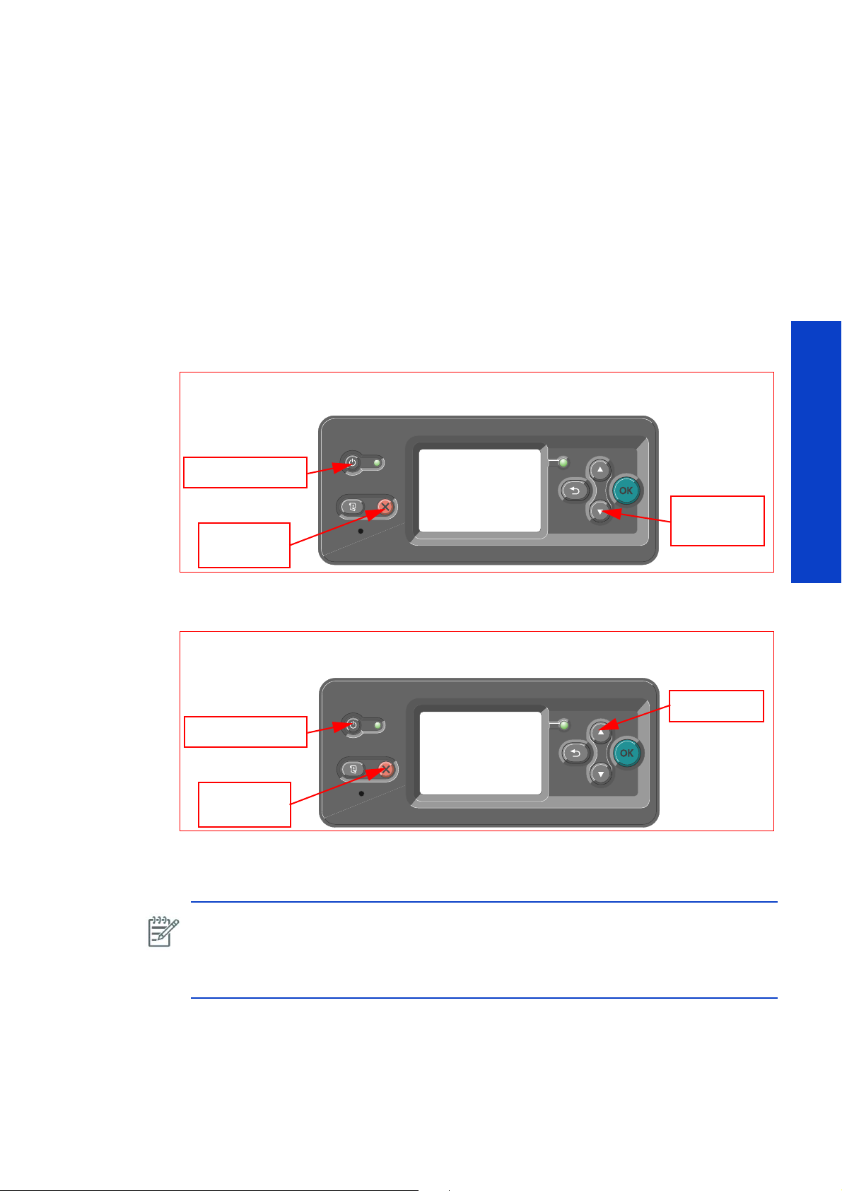
About the Service Menu
Hold Cancel
key
Switch Printer ON
Hold DOWN
key
P
H
O
N
E
SU
P
P
O
R
T
Hold Cancel
key
Switch Printer ON
O
N-
S
I
T
E
R
EPA
I
R
Hold UP key
The Service Utilities, Reset Life Counters, and Service Calibration menus are only available from the
service menu.
This special menu is ‚’hidden’ and requires a special access key combination to access it. Two menus
exist, one for the user and one for the service engineer, in order to prevent the user from changing
important settings like life counters or factory defaults.
Service Menu Key Combinations
Diagnostic mode
1. For Call Agents who will request the User to Perform certain troubleshooting action, hold the Down
arrow key and the Cancel key down and switch the printer ON using the front power switch. Watch the
LED light on the Front Panel.
Tests, Utilities & Calibrations
2. For On-Site Engineers, hold the Up arrow key and the Cancel key down and switch the printer ON
using the front power switch.
3. First it will be red for short time, then green for a longer time, then it will be off, and finally it will start
flashing green. As soon as it lights up green after being off, quickly release all three keys.
NOTE: If you restart the printer from the ACB-1 breaker switch or you do not press the service
key combination in time, press and hold the ON key for 1 second and release the key, the
printer will switch off within the coming 3-5 seconds. Do NOT leave the ON key pressed too
long, or the printer will restart again immediately. If this occurs, just press again the ON key
for 1 second and release it => the printer will switch off within the coming 3-5 seconds.
Service Tests, Utilities & Calibrations 271
Page 8
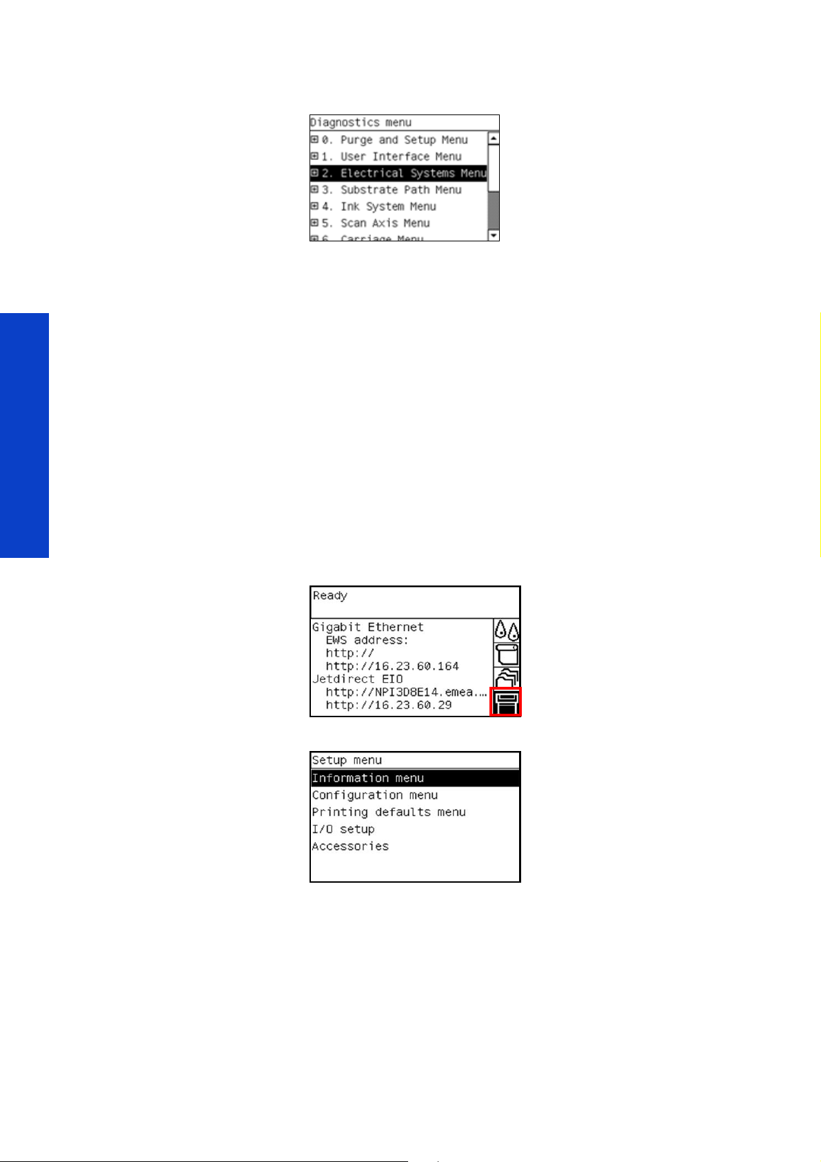
4. Once inside the Service Tests Menu use the Arrow keys to scroll through the Diagnostics menu. Press the
Enter key to begin a specific test when the required Service Test is highlighted.
Common reasons for failing to boot in diagnostic mode
It is important to press and hold the buttons exactly as described here.
1. With the Down (customer) or UP (CE) and Cancel keys already pressed and kept down, press the
On/Off button and keep it pressed until you see the green light switching on for the 2nd time..
2. A moment after pressing the On/Off button the green light comes on. Do not release the On/Off
button at this time. If you do then the diagnostic menu does not open and the printer starts normally.
• Keep all three buttons pressed down until you hear the beep sound.
• Only at the end of the boot process do you know if the printer has booted in diagnostic mode or in
normal mode.
• In case you do not have enough time, after having turned ON the big ON/OFF switch, to press the
3 keys -> hold down on the ON/OFF button (#3) for 1 second and release it; the printer will
switch off within the coming 3-5 seconds, and then you can start again the sequences (by pressing
on 3 buttons).
Test, Utilities & Calibrations
Service Menu
1. Select the setup icon from the Front Panel and press Enter.
The Printer displays the following menu:
2. Depending on the situation:
• Phone Support: Press and hold the Down key, and press the Cancel key at the same time.
• Onsite repair: Press on the Up key, and press on the Cancel key at the same time.
272 Service Tests, Utilities & Calibrations
Page 9

3. The Service menu is displayed.
NOTE: In case of 'phone support', the 'reset life counters Menu' is not displayed.
Tests, Utilities & Calibrations
Service Tests, Utilities & Calibrations 273
Page 10
Diagnostic Tests
If you need to troubleshoot a problem with the printer, see page 87.
Diagnostic tests help you determine which component is failing when you have a problem. This section
guides you through the diagnostic test procedures and provides information about each test.
0. Purge & Setup Menu
0.1 Purge ISM
Description
This is used to purge the Ink Supply Module. The test guides step by step the user to fill the tubes of the
ISM side with ink by one of two ways. This procedure is only performed during the installation process,
further details are available in the ‘Installation Guide’.
• Follow the user with instructions to fill the column of ink between Ink Cartridge connector and the
purge port.
• Opening the entry electrovalves and letting the ink fill the ISM system up to the quick connector.
NOTE: The printer can tolerate up to 20cm of air (the length of the bubble) in the tubes per
color, from the main ink electrovalve to the printhead, small pockets of bubbles are okay.
CAUTION: From the cartridge connector to the main ink electrovalve: NO bubble is accept-
able, or the printer can display an error message ‘unexpected empty cartridge’ (while there is
Test, Utilities & Calibrations
ink in the cartridge). The tube from the ISM ink tray to the ink cartridges are not transparent. In
case of any doubt, do not hesitate to refill the ink within the tubes (only this portion of tube).
CAUTION: Do not apply too much force the syringe or any tube or connection. Gently
manipulate the syringe during insertion to ink cartridges, purging ports, or printhead connec
tions.
Procedure
1. Disconnect the ink cartridges.
-
2. Connect the purge bags to the printer.
274 Service Tests, Utilities & Calibrations
Page 11
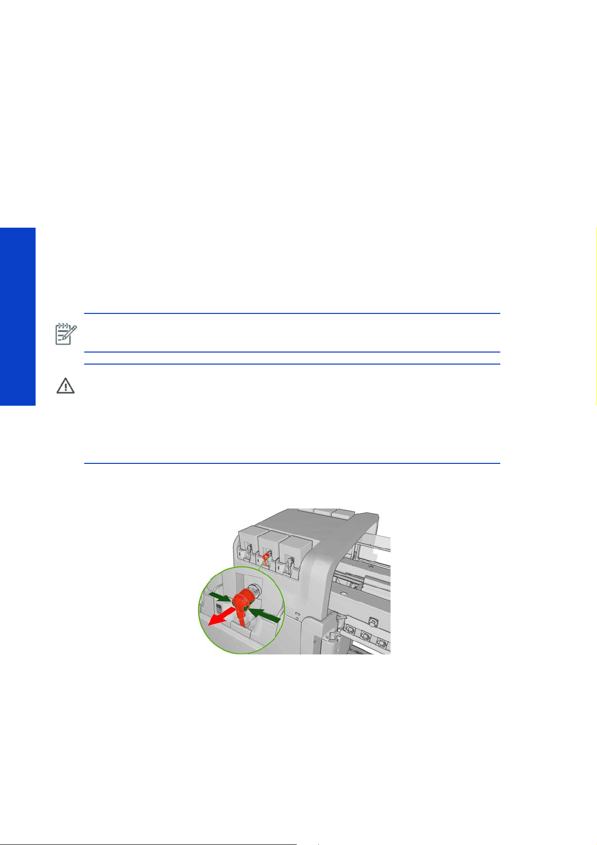
3. Disconnect the quick connector from the ISM..
CAUTION: The quick connector should always be handled with care and held by the pro-
vided protective tube, so as to avoid any over-stress on its internal fittings.
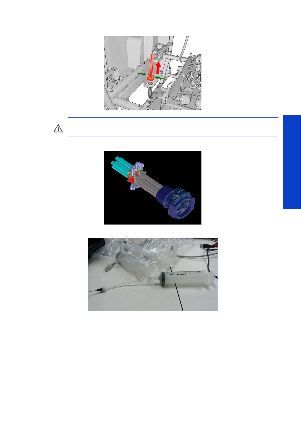
4. Connect the Purger Quick Connector to the ISM.
5. Screw the needles into all the syringes.
6. Go to the Diagnostics menu> 0. Purge Menu & Set Up Menu> 0.1 Purge ISM.
Tests, Utilities & Calibrations
Service Tests, Utilities & Calibrations 275
Page 12
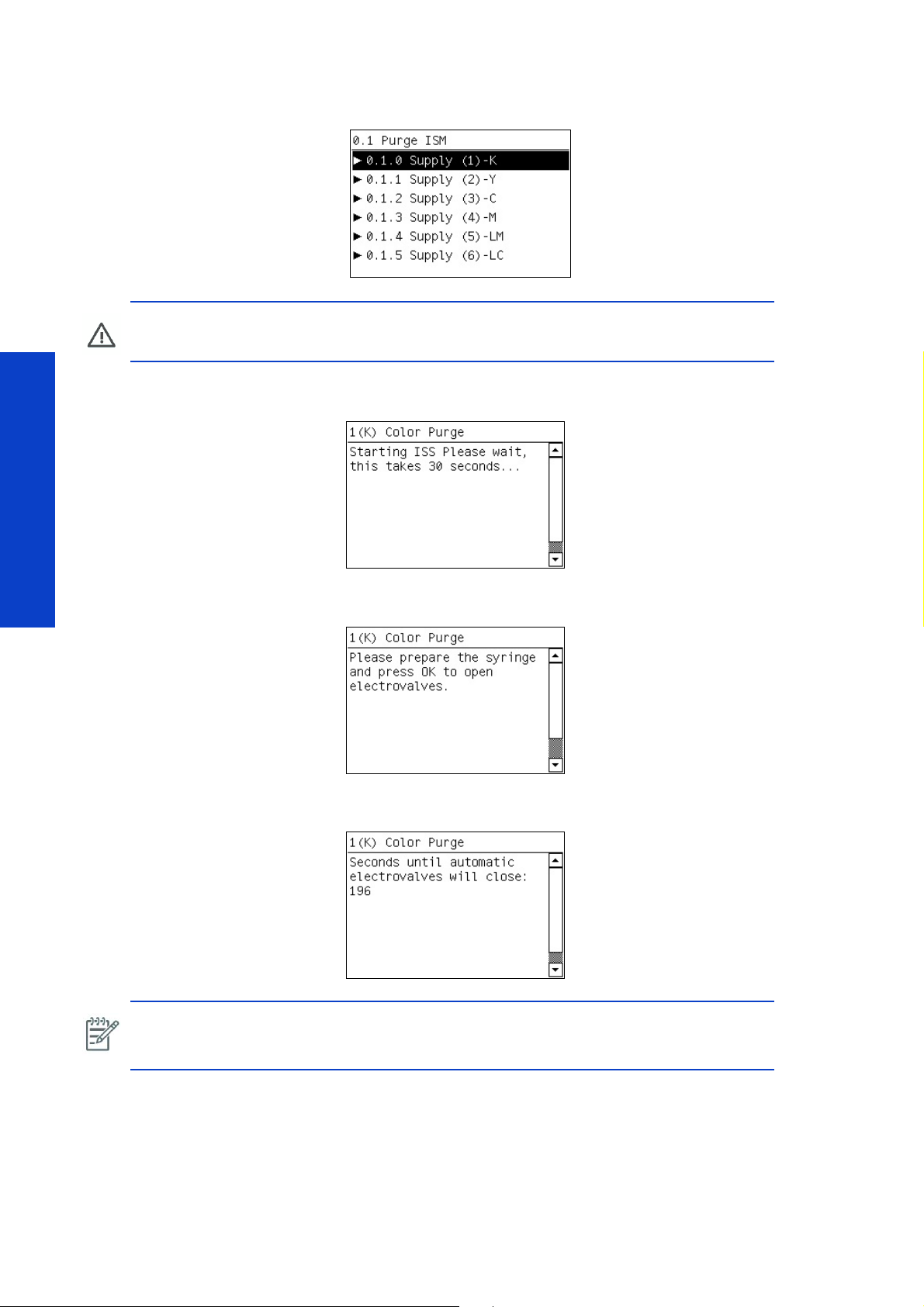
7. There is a special menu selection for each color line, each has the same identical operation, press ok to
select the color to purge
CAUTION: When selecting the option in the following procedure, do not push the ok button
more than once per selection.
8. The front panel will display the following message, in the initialization period, the electrovalve of the color
selected will open
.
and close several times to ensure it is functional.
9. The front panel displays the following message, press the ok key to open the electrovalve of the selected
Test, Utilities & Calibrations
color.
10. The front panel displays the time remaining that the electrovalve is open and beeps to indicate the open
status (in total 200 seconds)
NOTE: At this moment the EV will open if ink does not go beyond the EV, the part might
require a repair procedure. Try to open and close it several times using the 4.15.X service
procedure.
.
276 Service Tests, Utilities & Calibrations
Page 13
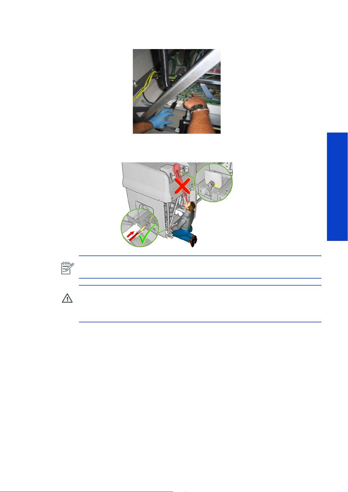
11 . Insert the syringe in the purging port (next to the ink pressure sensor) for the color selected, and slowly
push the ink until it clearly reaches the quick connector purger (first) and the purge bags (second).
If you run out of ink in the syringe, it is okay to refill the syringe from the ink cartridge. Keep track of how
much ink you remove from the ink cartridge, because you will be asked to report the quantity of ink taken.
Make sure the electrovalves are still open.
NOTE: Make sure you insert the syringe far enough into the port so that the tip of the syringe
engages with a small spring inside the port.
CAUTION: Never look away from the syringe. If you need to look at the purge bags or some-
thing else in the room, set down the syringe first. The ink system components are easily broken.
CAUTION: Do not insert the syringe if the electrovalves are not open, this will be noticeable
as there will be too much resistance when inserting the syringe.
• 1 = K
• 2 = Y
• 3 = C
• 4 = M
• 5 = LM
• 6 = LC
12. Remove the syringe from the purge port with a cloth to prevent spills.
13 . Press OK on the Front Panel to close the electrovalves.
Tests, Utilities & Calibrations
Service Tests, Utilities & Calibrations 277
Page 14

14 . Press OK to confirm that you have finished purging the ink tubes for the color selected.
15 . Disconnect the purge bag and connect the ink cartridge, and then press OK.
16 . If there is a connection error at this point the following message will be displayed.
Test, Utilities & Calibrations
Check the ink cartridge is correctly connected. Check the connector switch and cable connections (red
cable) to the ISM PCA
17. If there is no error at this point the following message is displayed.
The pressure must be above 1800 mpsi, this is to ensure that the ink pressure sensor is reading a good
value (1800mpsi is for a ink cartridge almost empty), this check prevents bubbles of air in the line (which
causes low ink pressure) which causes the system to mark the ink cartridge as empty. As in the next step
the printer will access the acumen and write it as empty if the pressure is very low.
For completely new ink cartridges the value should be around 2200-2300 mpsi. If the value does not
match the expected values, repeat the purging process of the column.
18 . If there is a failure with the Ink Pressure Sensor or a cable is disconnected, the front panel will display that
the ink pressure is above 3000 mspi, such as the message shown below.
278 Service Tests, Utilities & Calibrations
Page 15
If the above message is displayed, check the connections of the Ink Pressure Sensor cable. Check for any
similar problems with the other colors that share the same ink pressure sensor board, if these color also
have a problem, replace the board.
19. If there is no error at this point the following message is displayed.
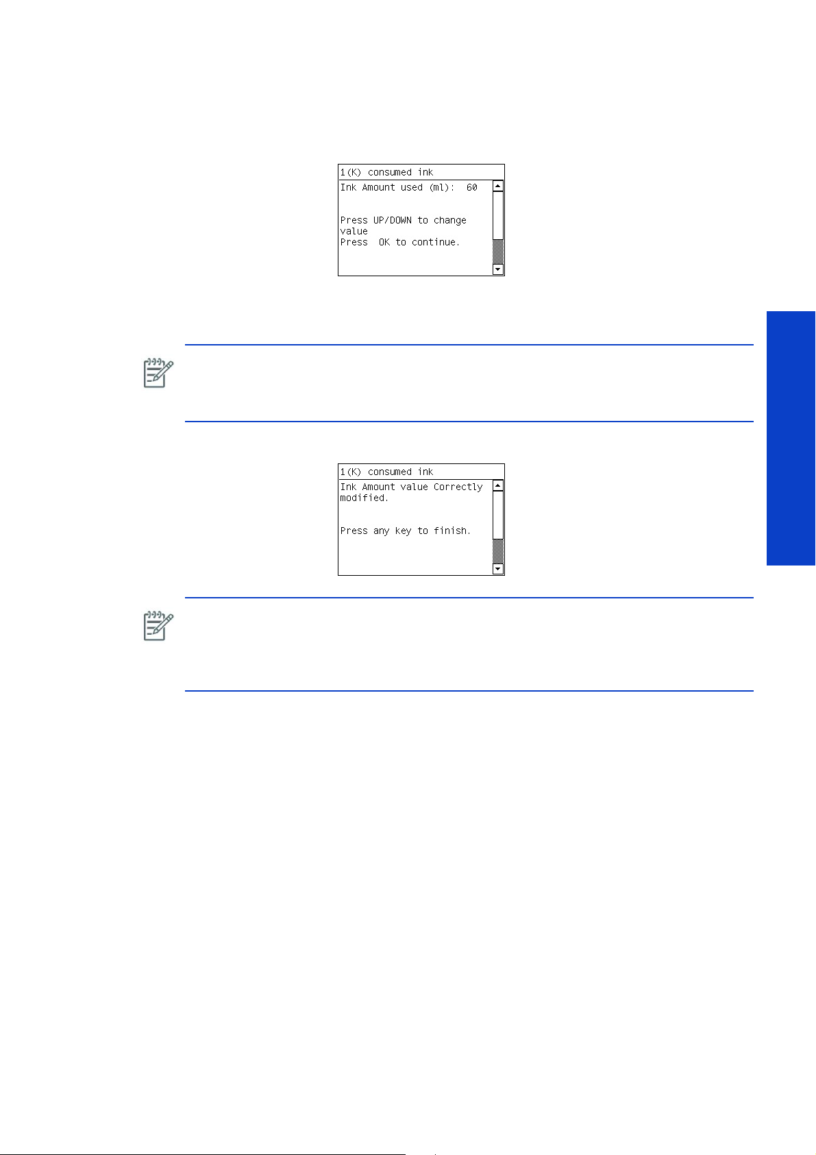
20. Enter the quantity of ink that was extracted from the ink cartridge (typically this is 60ml), press the ok key
when this is done.
NOTE: Entering the amount of ink taken from the ink cartridge correctly will have an impact
on the precision of the remaining ink that is displayed to the customer. The out of ink message
is independent of this value, which is solely dependant on the value detected by the ink
pressure sensor.
21. The following screen is displayed when the values have been entered.
NOTE: Checks are made of the values of the ink pressure sensor before finishing the
procedure. The reason for this is to ensure correct calibration before writing to the supply
acumen as empty (pressure values too low which might be due to air in the column of ink
between the supply and the ink pressure sensor). This check prevents displaying the ink
cartridge with incorrect remaining ink.
22. Select the next color and repeat.
23. Remove the quick connector purger.
0.2 Fill Intermediate Tanks
Description
This procedure is used to fill a new set of intermediate tanks with ink and should only be performed during
the printer’s installation (refer to the installation guide for details). The procedure first pressurizes and then
depressurizes the tanks to check the condition of the inner bag of the intermediate tank. The procedure
then fills the intermediate tanks with ink. This second procedure is time based and performed on one side
(intermediate tanks X.1) after the other (intermediate tanks X.2). While one side is refilled the other is semipressurized to control the refill. For the procedure to be performed there must be at least 1.5L of ink in the
ink cartridges, otherwise the system will halt the procedure.
Tests, Utilities & Calibrations
Procedure
1. Go to the Diagnostics menu 0. Purge and Setup Menu > 0.2 Fill intermediate tanks.
Service Tests, Utilities & Calibrations 279
Page 16
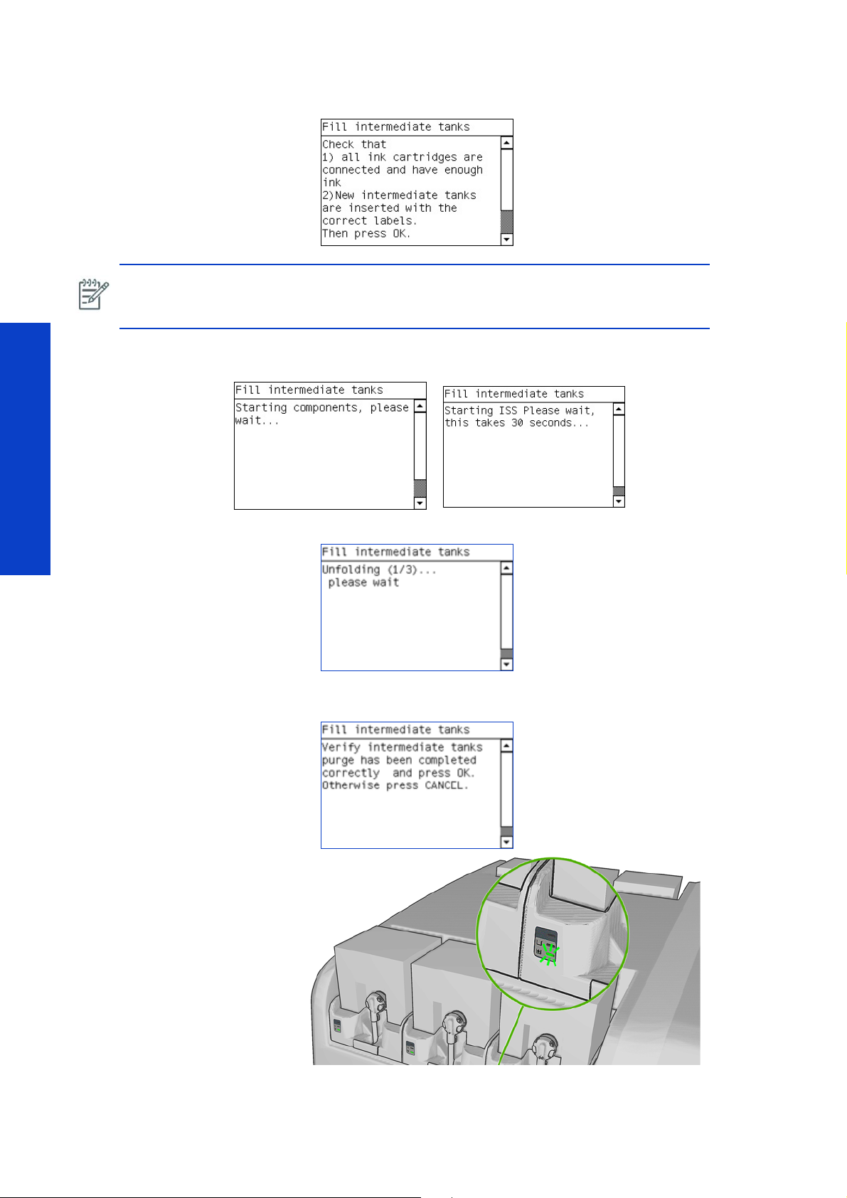
2. Ensure that all the intermediate ink tanks are installed, apply the labels (match them to the labels on the
printer), and confirm that they are installed from the Front Panel.
NOTE: This procedure sets the amount of ink in the intermediate tanks, if the process is
interrupted or not fully performed for any reason, the procedure is forced to run again until it is
successful.
3. The following messages are displayed while the printer starts the various subsystems in order to perform
the procedure.
The refill process takes approximately 25 minutes.
4. The printer unfolds the intermediate ink tanks. When the process is finished, press any key to continue.
Test, Utilities & Calibrations
5. The printer fills the intermediate ink tanks. When the process is finished, check that the ink cartridge LED
is green and press any key to continue.
280 Service Tests, Utilities & Calibrations
Page 17
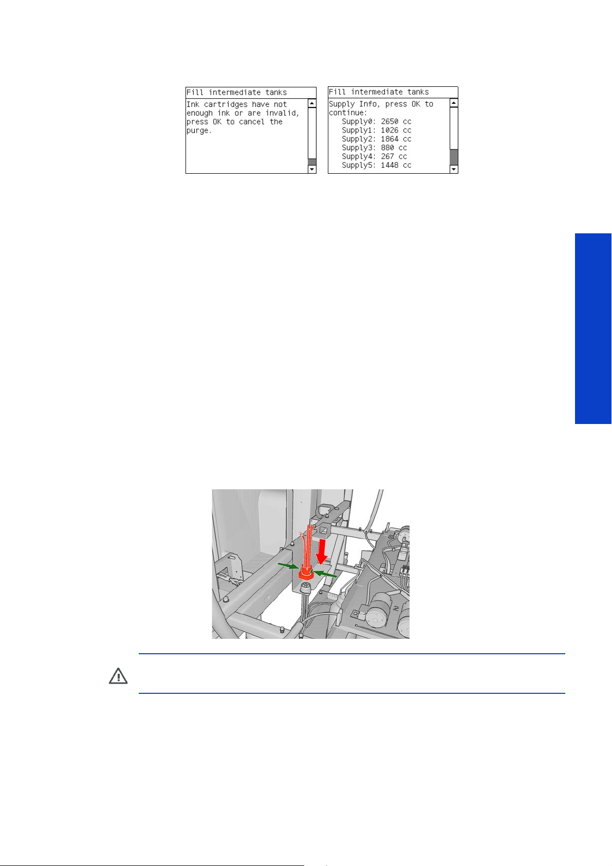
6. If there is a failure at this point because of insufficient ink in the ink cartridge, the following message is
displayed:
The supply ink information is obtained from the acumen of the supplies. If any of the values are 0 or
non-read, check the connections of the ink cartridges or replace them if they are not working.
Nomenclature used:
• Supply 0: Black Color Cartridge
• Supply 1: Yellow Color Cartridge
• Supply 2: Cyan Color Cartridge
• Supply 3: Magenta Color Cartridge
• Supply 4: Light Magenta Color Cartridge
• Supply 5: Light Cyan Color Cartridge
0.3 Purge Printer Tubes
Description
This process purges the TRS (Tube route system) from the ISM up to the print heads during the installation
process. Further details of the process cab be found in the installation guide. The system pressurizes the
ISM system to push ink into the tubes by placing the air purgers in the Printhead positions the air comes
out filling the tubes. The test pressurizes the tubes constantly until the user finishes the operation.
Procedure
1. Go to the Diagnostics menu and select 0. Purge and Setup Menu > 0.3 Purge Printer Tubes.
2. Connect the quick connector.
WARNING!: The quick connector should always be handled with care and held by the pro-
vided protective tube, so as to avoid any over-stress on its internal fittings.
Tests, Utilities & Calibrations
Service Tests, Utilities & Calibrations 281
Page 18
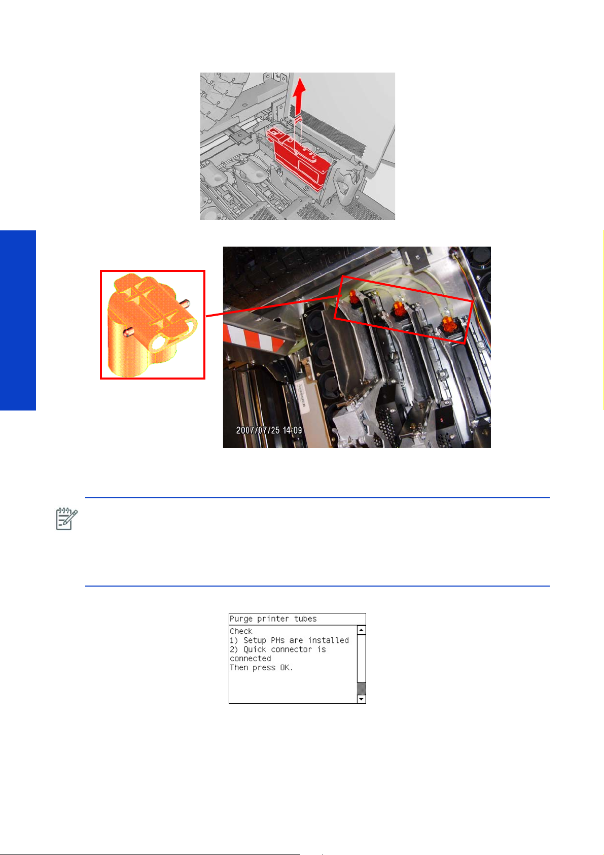
3. Printheads must not be present in the printer before at the start of the procedure. Remove the printheads.
4. Install the air purge connectors.
Test, Utilities & Calibrations
Ensure all purgers are placed in the FI connectors. The printer will then pressurize the system allowing ink
to flow through the tubes from the intermediate tanks. The filling of the tubes will take about 100cc of ink.
NOTE: If the tubes have been cleaned before it is possible that some remaining water in the tubes can
trap the purgers, not allowing the air to come out. In this case used a syringe to extract the remaining
air and ensure the ink reaches the Fluid interconnects.
NOTE: In case you do not have the purge connector, you can use a syringe as described before, but
if you need to have the air pressure set for a long time, perform the following other diagnostic tool
'4.12 Ink Pressure At Pen refer to page 328.
5. Press OK to purge the tubes.
282 Service Tests, Utilities & Calibrations
Page 19
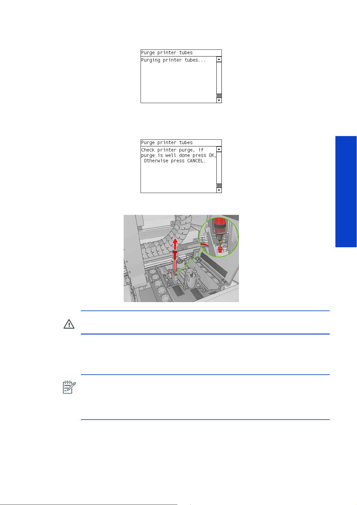
6. At this point, the printer sends ink to the carriage purging the tubes, this process takes approximately 5
minutes.
7. After a few minutes the following message is displayed, the Front Panel prompts you to confirm that ink
has reached the air purge connectors. Look at the air purge connectors and confirm that each color has
arrived to the connector.
pressurize the tubes system by pressing Cancel.
8. If the ink did not arrive to the air purge connector successfully, remove the air purge connector and insert
a syringe of the same color. When the ink reaches the syringe, the printer tubes are purged.
Press ok if the purge was completed successfully. At this point it is possible to re-
WARNING!: Do not pull on the plunger of the syringe. The pressure in the tubes will force
the ink into the syringe itself.
9. If the ink does not arrive to the syringe, press CANCEL and repeat Purge Menu > Purge Printer
Tubes.
10. If the tubes are purged correctly, remove the air purge connectors and press OK to finish.
NOTE: Wear latex gloves and use a cloth when you remove the air purge connectors.
NOTE: The printer can be pressurized manually using other methods available in the
diagnostics (such as starting up the printer’s air pumps. Use this procedure if problems appear
and additional troubleshooting required (such as verification that the system is pressurizing
correctly). However ensure the TRS purged flag is reset (diagnostics ‘0.9 TRS as purged’.
Tests, Utilities & Calibrations
Service Tests, Utilities & Calibrations 283
Page 20
0.4 Purge Ink Used Menu
Description
In the case where ink is removed from the ink supplies to purge additional purging operations, this menu
enables the user to take into account the quantity of removed ink from the supply memory, this gives a
more precise measure of the ink accounted for in the IPS of the printer. The procedure can be applied to
each color line.
Procedure
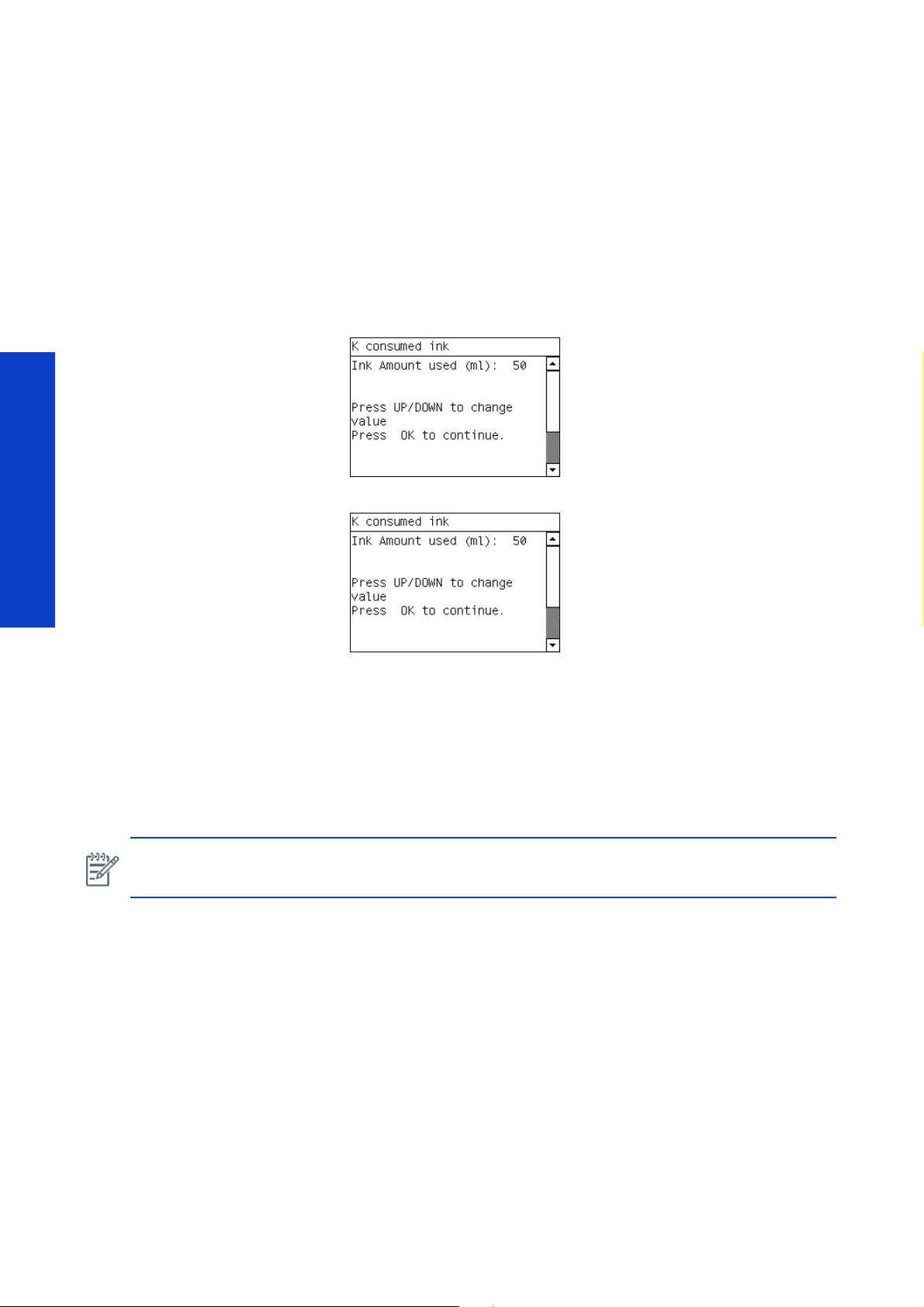
1. Go to the Diagnostics menu and select 0. Purge and Setup Menu > 0.4 Purge Ink Used Menu.
2. The front panel displays the following message, use the up and down keys to change the value displayed
to the amount of ink that was removed from the ink cartridge for purging purposes.
3. The front panel displays the following message and confirms the amount entered, press ok to finish.
Press the ok key.
Test, Utilities & Calibrations
If the above confirmation screen is not displayed, this could indicate an error writing the value to the
acumen of the ink cartridge, in this case check the connections to the ink cartridge.
0.5 3ph AC Volt Setup Menu
Description
This menu sets the voltage of the 3 phase (phase to phase) voltage in the printer. This value must be set
correctly for the heating and curing systems in the printer to work correctly.
NOTE: 3 Phase voltage values below 190V and above 430V are not supported by the printer.
Procedure
1. Go to Diagnostics menu and select 0. Purge and Setup Menu > 0.5 AC Volt Setup Menu.
284 Service Tests, Utilities & Calibrations
Page 21
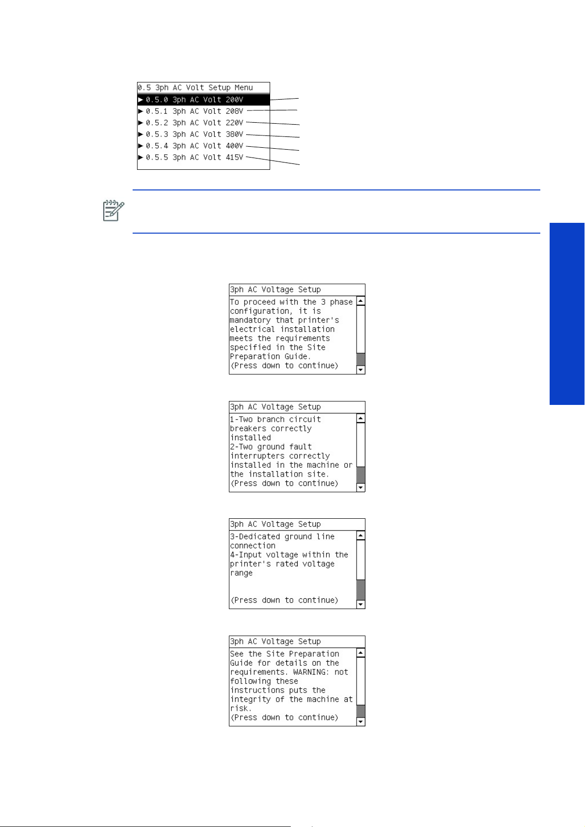
2. The following screen is displayed, select the correct voltage of the line voltage of the customers site, and
• Select this for line voltages below 204V
• Select this for line voltages below 205V-214V
• Select this for line voltages below 215V-240V
• Select this for line voltages below 360V - 390V
• Select this for line voltages below 391V-407V
• Select this for line voltages below 408V and above
select the ok key.
NOTE: It is possible to check the current voltage setting of the printer via the service plot by
going to ‘IPS Select information>Service Information’ (available from firmware version
14.2.2.1 and IPS 3.5 and greater)
3. The following messages are displayed in order to confirm that the appropriate safety requirements have
been met when installing the printer and selecting the voltage value. Read each message and press the
down arrow to continue only when you are sure the corresponding safety requirement has been met.
4. The following message is displayed, press the down arrow to continue.
5. The following message is displayed, press the down arrow to continue.
6. The following message is displayed, press the down arrow to continue.
Tests, Utilities & Calibrations
Service Tests, Utilities & Calibrations 285
Page 22

7. The following message is displayed, press the down arrow to continue.
8. The following message is displayed, press the down arrow to continue.
0.5.6 Voltage Configuration
Description
This menu enables you to see the current voltage configuration selected.
Procedure
1. Go to Diagnostics menu and select 0. Purge and Setup Menu > 0.5 AC Volt Setup Menu >
Test, Utilities & Calibrations
0.5.6 Voltage Configuration
2. The following screen is displayed.
3. The current voltage selected is displayed.
The values displayed will be 200, 208, 220, 380, 400 or 415 depending on the current configuration. If
the printer does not have any configration selected the display will show NO CONFIGURATION. To set a
voltage configuration refer to page 284.
0.6 Force Normal Boot
Description
This test changes the boot up parameter of the printer to start up in normal mode (also known as printer
mode)
286 Service Tests, Utilities & Calibrations
Page 23
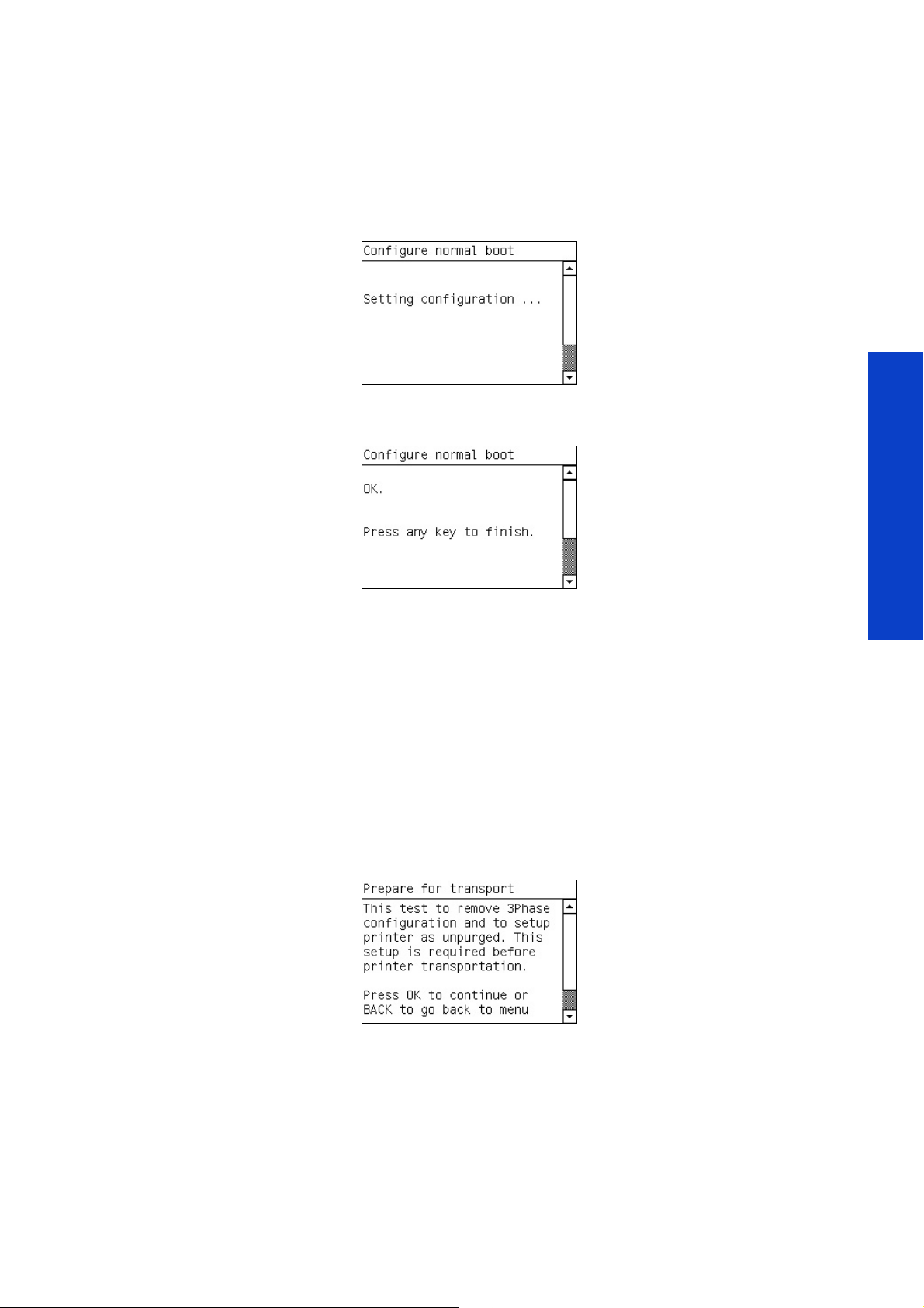
After initial set up of the printer in Diagnostics boot up, this procedure is selected to start up the printer
normally. This procedure is required to reset the printer back to normal boot mode operation after ‘1.0
Force diagnostics boot mode’ has been performed.
Procedure
1. Go to Diagnostics menu and select 0. Purge and Setup Menu> 0.6 Force Normal Boot
2. The following screen is displayed while the system is changed to boot up in Normal Boot mode.
3. When the process has finished, the following screen is displayed confirming the printer will now automat-
ically boot up in normal printer mode., press ok to finish.
0.7 Prepare for transport
Description
This procedure is used to prepare the printer for transportation.
The procedure deletes the 3Phase configuration parameter, forcing the selection again of the 3 Phase
configuration once in the customer new premises. In addition where the transportation environment was
below 5 degrees and ink flushing was performed, the procedure enables the user to remove the ISM and
TRS purged status which allows a re-purging of the printer.
Procedure
1. Go to Diagnostics menu and select 0. Purge and Setup Menu> 0.7 Prepare for transport
2. The front panel displays the following message, press ok to continue.
Tests, Utilities & Calibrations
Service Tests, Utilities & Calibrations 287
Page 24
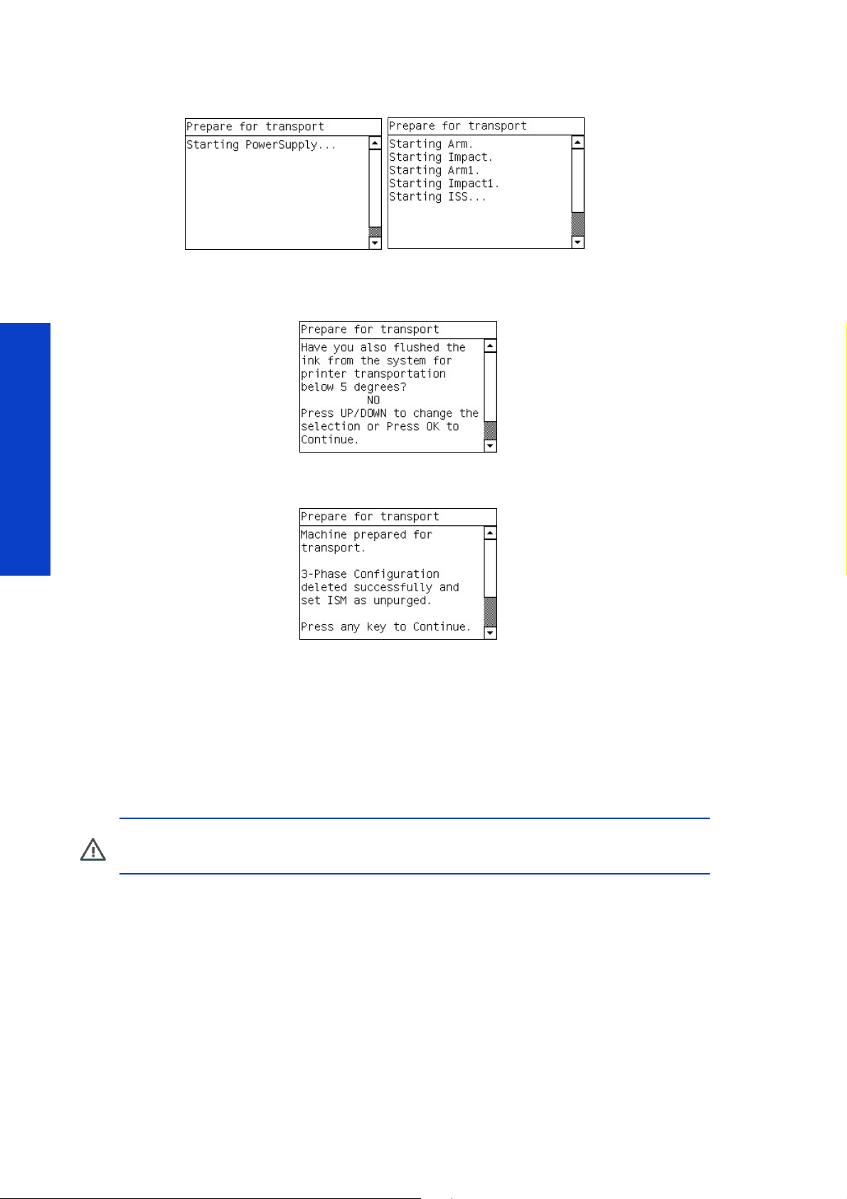
3. The front panel displays the following messages, and the 3 phase power configuration is reset in the
printer.
4. The front panel displays the following message. If yes is selected, the ISM and TRS purge status is reset to
0, forcing the purging procedure to be performed again, (this can be reversed using the procedure 0.8
and 0.9).
5. The following message is displayed confirming the printer’s voltage setting has been reset and the purge
status of the printer has been reset to 0 (Unpurged), press any key to finish the procedure.
If no is selected at this point the procedure will finish.
Test, Utilities & Calibrations
0.8 Set ISM as Purged
Description
This procedure is used to set the ISM purged status in the NVM. The test is used if the standard ISM purging
procedure failed (0.1 Purge ISM page 274) and the purging process was manually performed and the
status needs to be set using this procedure to ‘Purged’.
CAUTION: If this procedure is performed and the printer has not actually been purged, print-
ing failures and possible printhead damage will probably occur.
Procedure
1. Go to Diagnostics menu and select 0. Purge and Setup Menu> 0.8 Set ISM as Purged
288 Service Tests, Utilities & Calibrations
Page 25
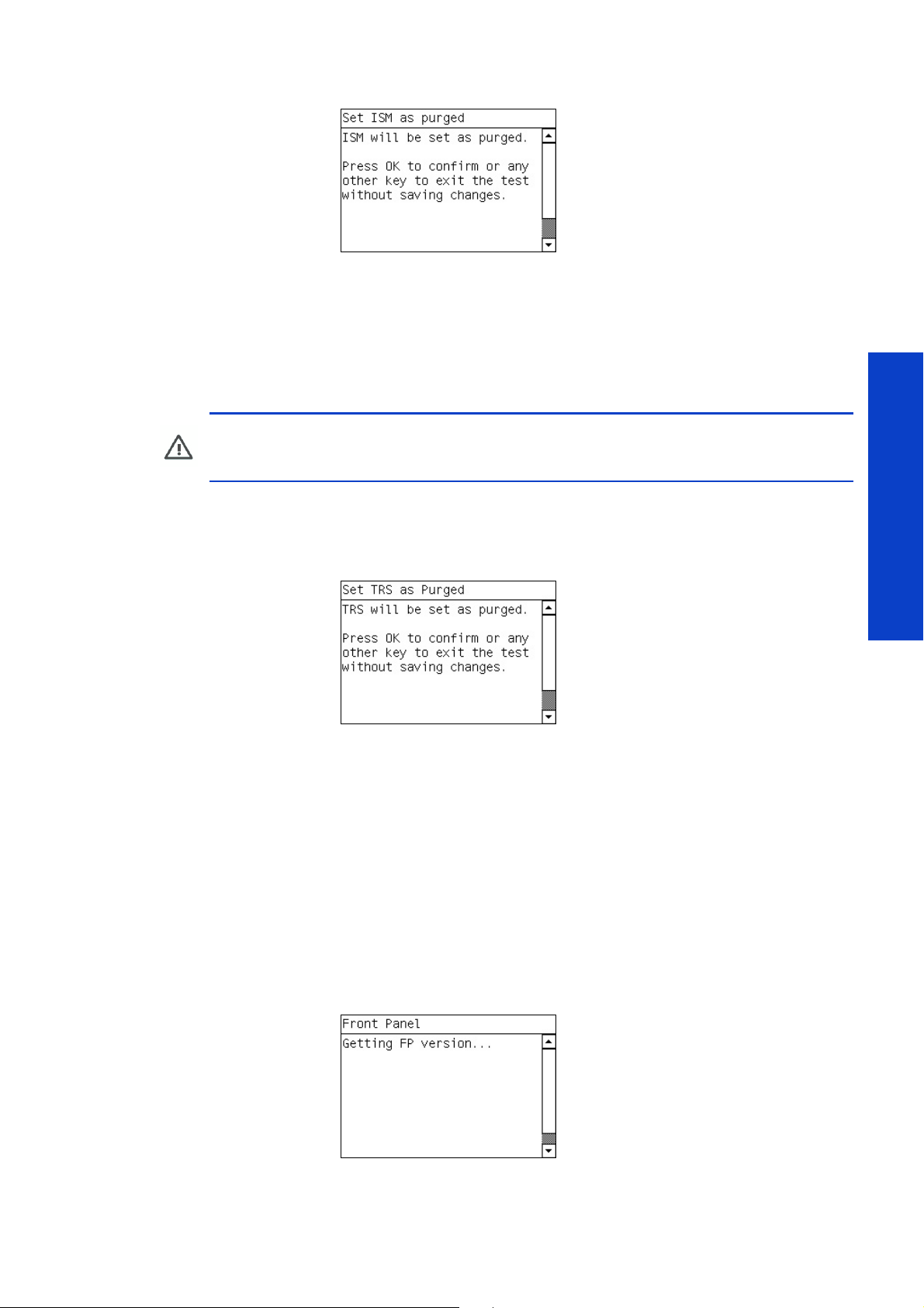
2. The following message will be displayed, press the ok key to set the ISM status as ‘Purged’.
0.9 Set TRS as Purged
Description
This procedure is used to set the TRS purged status in the NVM. The test is used if the standard TRS purging
procedure failed (0.3 Purge ISM page 281) and the purging process was manually performed and the
status needs to be set using this procedure to ‘Purged’.
CAUTION: If this procedure is performed and the printer has not actually been purged, print-
ing failures and possible printhead damage will probably occur, (because there is air within
the tubes and no ink).
Procedure
1. Go to Diagnostics menu and select 0. Purge and Setup Menu> 0.9 Set TRS as Purged
2. The following message will be displayed, press the ok key to set the TRS status as ‘Purged’.
1.0 User Interface Menu
1.1 F ron t P a nel
Description
This procedure checks the correct functionality of the keys on the front panel and the correct operation of
the pixels in the display. The procedure also performs a quick front panel internal electronics check.
Procedure
1. Go to Diagnostics menu and select 1.0 User Interface Menu> 1.1 Front Panel
2. The following message will be displayed, the version of the firmware is checked and the hardware ver-
sion.
Tests, Utilities & Calibrations
Service Tests, Utilities & Calibrations 289
Page 26
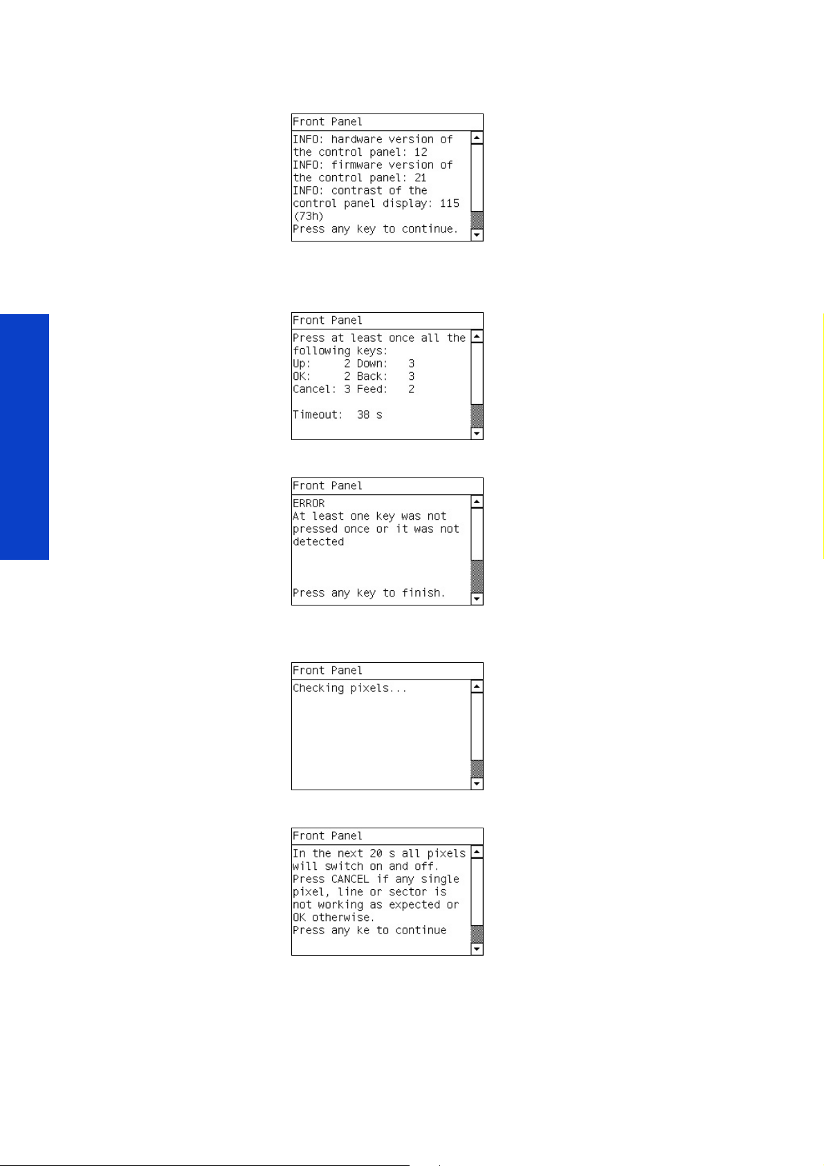
3. If this is displayed correctly, as shown here, this would indicate that the electronics of the front panel are
functioning correctly,
4. Press all the keys of the front panel, multiple times, each press of the key is recorded in the message dis-
played. Make sure the keys are pressed firmly, so that they can be registered correctly on the display. The
procedure times-out after a while.
If any of the keys are register as 0 presses, an error message is displayed and the test fails.
press any key to continue
Test, Utilities & Calibrations
5. If there is no error at this point the test continues, the front panel displays the following screen which tests
all the pixels on the screen of the front panel.
6. The front panel displays the following message, wait for 20 seconds to elapse for the start of the pixel test.
290 Service Tests, Utilities & Calibrations
Page 27
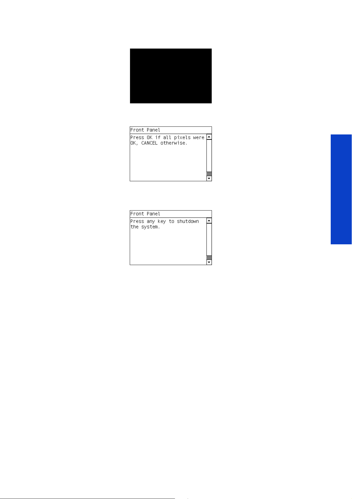
7. The front panel screen will go completely black, check to see if there are any white pixels showing, which
would indicate a failure of one or multiple pixels on the screen.
8. The front panel will display the following message, if there were no white pixels showing and the screen
was completely black, press the ok key.
If there were white pixels showing on the screen, press cancel to fail the test and replace the front panel.
9. If the screen passes the test, the following message is displayed, press any key to shutdown the printer.
2. Electrical Systems Menu
2.1 ECabinet
Description
This procedure checks the functionality of electronics in the ECabinet. The following are turn on for the
purposes of the functionality:
• Power Supply Voltage test (main power supply)
• Vacuum Transformer test
• Curing System Fans test
• Temperature Sensors test (communication temperature values)
• Heating and curing modules configuration
Procedure
1. Go to Diagnostics menu and select 2. User Electrical Systems Menu> 2.1 ECabinet
Tests, Utilities & Calibrations
Service Tests, Utilities & Calibrations 291
Page 28
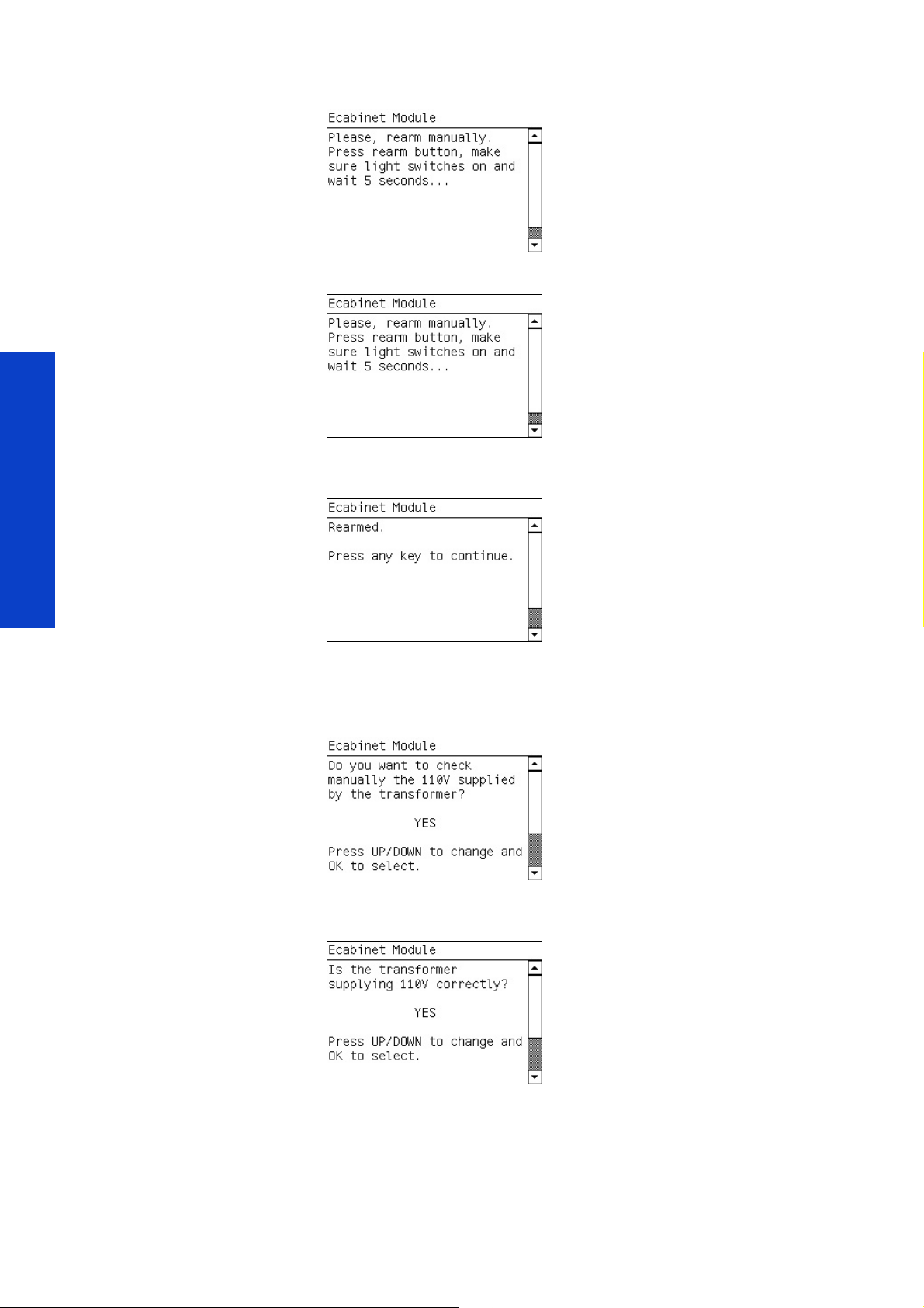
2. The following screen is displayed, reset the circuit breakers and make sure there is a light showing.
3. The following screen is displayed, reset the circuit breakers and make sure there is a light showing.
4. When the circuit breakers have been reset the front panel displays the following message, press any key
to continue.
Test, Utilities & Calibrations
The printer starts the various subsystems required to perform the tests, if there are any system errors at this
point refer the troubleshooting chapter.
5. The front panel will display the following message, select yes and press ok.
6. Use a voltameter to test for 110v in the output voltage point of the transformer or the terminal blocks to the
vacuum pump, if there is 110v present, select yes and press ok.
If 110v is not present, select no and press ok. The printer will shut down and the failure can be repaired.
292 Service Tests, Utilities & Calibrations
Page 29
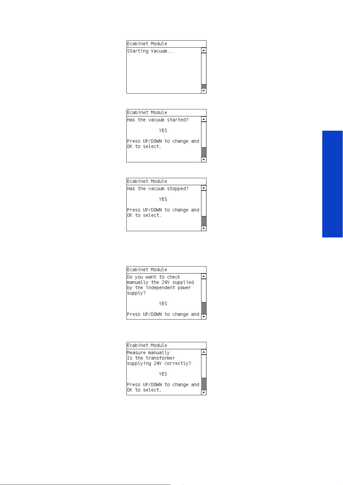
7. If there is no failure, the front panel displays the following message, and the vacuum system is turned on.
8. The front panel displays the following message, press yes if the vacuum has started.
9. The front panel displays the following message, press yes if the vacuum has stopped.
If there is an error with the Vacuum functionality, this would indicate an error with the Vacuum
Transformer, press no and the printer will shut down so the appropriate repair can be made.
10. If there is no error at this point the following message is displayed, select yes and press the ok key.
11 . Use a voltameter to test for 24v in the output voltage point of the 24v Secondary PSU, if there is 24v
present, select yes and press ok.
Tests, Utilities & Calibrations
If 24v is not present, select no and press ok. The printer will shut down and the failure can be repaired.
Service Tests, Utilities & Calibrations 293
Page 30

12. If there is no error at this point the following message is displayed, and the curing fans are turned on,
select yes and press the ok key if the curing ar functioning.
If the curing fans do not turn on, select no and press ok. The printer will shut down and the failure can be
repaired.
13 . If there is no error at this point the following message is displayed, and the heater is turned on to check if
the Print zone IR temperature sensor displayed is raised to an appropriate level, press any key to continue.
If the Print zone temperature is not displayed correctly on the front panel, this would indicate an error with
the connections or failure of the Print Zone IR temperature sensor.
Test, Utilities & Calibrations
14 . The following message is displayed, and the curing module is turned on to check if the Curing IR temper-
ature sensor displayed is raised to an appropriate level, press any key to continue.l.
If the Curing temperature is not displayed on the front panel, this would indicate a indicate an error with
the connections or failure of the Curing IR temperature sensor.
15 . The front panel displays the following message, and the Heating and Curing modules are turned on to
high.
294 Service Tests, Utilities & Calibrations
Page 31

16 . The front panel displays the following message, while the Heating and Curing modules are turned on and
the temperature is stabilized.
The Heating and Curing modules are turned on high (see warning below), check that they are heating
up, if they do not this would indicate an error with the heating and curing modules which must be
repaired.
WARNING!: This procedure will set the Heating and Curing modules to a very high temper-
ature of 100 Degrees, please careful as the media Loaded could be damaged at
100 degrees. It is recommended to use only a media strip for the curing temperature sensor
to be able to read, and under controlled circumstances, check the operation of the heating
and curing modules at 100 degrees.
2.2 Main Electronics Menu
2.2.1 Electronics Control
Description
This procedure is a test to check the various boards and communication buses of the printer, to ensure
they are installed/connected and functioning correctly. The following boards are checked:
• Formatter board
• Power Supply board
• Main interconnect (naming)
• PrintMech
• Engine Boards
• Carriage Board communication
• ISS Board communication
Procedure
1. Go to Diagnostics menu and select 2. User Electrical Systems Menu> 2.2 Main electronics
Menu> 2.2.1 Electronics Control.
1. The front panel displays the following message, select yes and press ok.
Tests, Utilities & Calibrations
Service Tests, Utilities & Calibrations 295
Page 32

• The printer checks that the Formatter Board communicates correctly, press any screen to continue.
• The printer checks that the CPU fan is working correctly and the speed can be controlled by the
firmware on the Formatter board, press any key to continue.
• The printer checks that the main memory reads and writes correctly, and that the size (256 mb) is
correct, press any key to continue. If no is selected the test will finish and the printer will shut down.
Test, Utilities & Calibrations
2. The front panel displays the following message, select yes and press enter.
3. The front panel displays the following message. The printer verifies that the Main Non-Volatile Memory
(NVM), located on the Hard Disk System, and Main NVM backup, located on the Main Interconnect
Board, match.
If either the Hard Disk System or the Main Interconnect Board have been replaced, they may not match.
The printer also verifies that the serial number and part numbers are correct and use the correct format. If
the versions do not match, the printer displays the serial numbers and part numbers of the NVM and NVM
backup.
If necessary, the printer asks you if you want to force the NVM versions to synchronize. Press ok to
synchronize the NVM or cancel to leave them not synchronized.
296 Service Tests, Utilities & Calibrations
Page 33

4. If there is no problem at this point the following screen is displayed, press any key to continue.
5. The front panel displays the following message, select yes and press ok.
The electrical subsystems start up in order to perform the test.
6. The front panel displays the following message, select yes and press ok if you can see the LED located in
the Electronics box light up.
If the LED in the Electronics box does not light up, select no and the test will fail and the printer will shut
down in order to make the appropriate repair.
7. If there is no problem at this point the front panel will display the following message, select yes and press
ok.
Tests, Utilities & Calibrations
8. The printer checks that the Main Interconnect Board receives the correct voltage, can communicate with-
out failure, and receives the input signals correctly.
Service Tests, Utilities & Calibrations 297
Page 34

9. If there is no problem at this point the printer displays the following message. The printer checks the print-
head cleaning roll close position switch, the sliding door switch, and the top cover window switch. Press
any key to continue.
If there is a problem at this point the test will fail and the printer will shut down in order to make the repair.
10. If there is no problem at the point the front panel will display the following message, select yes and press
the ok.
11 . The front panel displays the following message, the printer checks that the Printmech Board receives the
correct voltage (42 V), can communicate without failure, and tries to connect to an element using the print
Test, Utilities & Calibrations
mech.
If there is a problem at this point the test will fail and the printer will shut down in order to make the repair.
12. If there is no problem at this point the front panel will display the following message, select yes and press
the ok.
-
298 Service Tests, Utilities & Calibrations
Page 35

13 . The printer checks the functionality, configuration, microprocessors operation and memory of the Upper
and Lower Engine PCI Board.
If there is a problem at this point the test will fail and the printer will shut down in order to make the repair.
14 . If there is no problem at this point the front panel will display the following message, select yes and press
the ok.
The printer starts the various subsystems required to perform the tests, if there are any system errors at this
point refer the troubleshooting chapter.
15 . If the printer successfully detects the Remote Controller Boards and Main interconnect board, the front
panel displays the following message.
If there is a problem at this point the test will fail and the printer will shut down in order to make the repair.
Tests, Utilities & Calibrations
16 . If there is no problem at this point the front panel displays the following message, select yes and press ok.
Service Tests, Utilities & Calibrations 299
Page 36

17. The printer checks that the carriage receives the correct voltage without failure and that the Trailing
Cables can communicate with the Carriage Printhead Board Assemblies.
18 . The printer sends a signal to the carriage and asks you to look at the 24 V Carriage LED to verify that the
LED is on and the signal arrives, select yes if the LED light up.
If the LED does not light up select no and the test will fail and the printer will shut down in order to make
the repair.
19. The printer asks you if you want to perform the ISS test, select yes and press ok.
20. The front panel displays the following messages and the printer checks the communications between the
printer and the Ink Supply System board. The printer reads and displays the IDS revision value to check
IDS connectivity with ADC. The printer asks you to verify that all the ink cartridges are connected cor
rectly. Verify that all ink cartridges are connected correctly. If an ink cartridge is not connected, connect it
now.
-
Test, Utilities & Calibrations
21. If the communications between the printer and the board are ok the front panel displays the following
message, press any key to finish the test and shutdown the printer.
If there is a problem at this point the test will fail and the printer will shut down in order to make the repair.
2.2.2 Hard Disk Drive
Description
This test checks the hard disc drive to make sure that it is working correctly, the checks include following:
• Protection status test (protected/not protected)
• Partition configuration test
• System file contents (sanity check for critical files)
Procedure
1. Go to Diagnostics menu and select 2. User Electrical Systems Menu> 2.2 Main electronics
Menu> 2.2.2 Hard disk Drive.
300 Service Tests, Utilities & Calibrations
Page 37

2. The front panel displays the following message, select yes and press ok.
3. The printer reads the protection status of the hard disc drive and displays it on the front panel. Press any
key to continue.
4. The front panel displays the following message, select yes and press ok.
5. The printer checks the hard disc drive partitions for faults and displays the results on the front panel, press
any key to continue.
6. The printer reads and displays the current file system contents of the formatted partitions of the hard disc
drive, press any key to continue.
7. The front panel displays the following message, select yes and press ok.
Tests, Utilities & Calibrations
Service Tests, Utilities & Calibrations 301
Page 38

8. The printer performs a sanity check of the hard disc drive to check the hard disc drive consistency. A
progress value is displayed to indicate the percentage to completion.
9. If the status of the Disk is ok, the following screen is displayed, press any key to finish the test and shut
down the printer.
2.2.3 IO Information
Description
This test shows the LAN configuration data, and tests the communication, which can help when
troubleshooting or setting up a network. The information displayed is the following:
Test, Utilities & Calibrations
• IP address
• Gateway address
• Subnet mask
• Connectivity with the Internal Print Server
Procedure
1. Go to Diagnostics menu and select 2. User Electrical Systems Menu> 2.2 Main electronics
Menu> 2.2.3 Connectivity Check.
2. The front panel displays the following message, while the printer retrieves the IO information.
3. When the printer has retrieved the information it is displayed on the front panel.
302 Service Tests, Utilities & Calibrations
Page 39

4. The following message is displayed, select yes and press ok to check the connectivity between the printer
and the IPS (DFE).
5. The front panel displays the instructions on how to check the connectivity. From the IPS go to ‘Run’>enter
the word ‘CMD’>enter the following ‘Ping ‘the IP address of the PC’>Press enter.
6. If there is connectivity select OK, if any packets were lost, select No. If yes is selected the printer shut
down.
If there is a problem with the connectivity, the test fails.
2.2.4 Unit Information
Description
This procedure retrieves printer information and displays the results on the front panel. This information is
useful for obtaining internal printer information for use in networking or checking the firmware version etc.
• Firmware version
• Serial Number
• Par t Number
• Prototype Name
Procedure
1. Go to Diagnostics menu and select 2. User Electrical Systems Menu> 2.2 Main electronics
Menu> 2.2.4 Unit Information.
Tests, Utilities & Calibrations
Service Tests, Utilities & Calibrations 303
Page 40

2. The printer reads and displays the printer unit information, press any key to finish the test and the printer
shuts down.
2.2.5 71.X:19 Recovery
Description
The SE 71.5:19 and SE 71.6:19 Recovery test resets the serial number and the part number in case the
Hard disk, Main Interconnect Board, and/or Ink System Main Board were replaced at the same time
which causes an SE 71.5:19 or SE 71.6:19.
Procedure
1. Go to Diagnostics menu and select 2. User Electrical Systems Menu> 2.2 Main electronics
Menu> 2.2.5 71.X:10 Recovery.
2. The printer reads and displays the serial number and part number of the HDD and the EEPROM, select
which ones are correct and press ok.
Test, Utilities & Calibrations
2.2.6 Set SN and PN
Description
This test displays and permits the engineer to set the Serial Number and Part Number of the printer. Use
this procedure only in case of critical failure of both NVM main and backup and loss of the Serial Number
and Part Number of the printer. Note: The Tests is protected with the code "NPI" to enter in order to prevent
the user performing this procedure.
Procedure
1. Go to Diagnostics menu and select 2. User Electrical Systems Menu> 2.2 Main electronics
Menu> 2.2.6 Set SN and PN.
304 Service Tests, Utilities & Calibrations
Page 41

2. The front panel displays the following message, enter the password in order to get access to this function-
ality. The password is NPI.
CAUTION: Changing the product number, could damage the printer. In case of any doubt
on the product number, it is marked on the top left side of the e-cabinet.
3. The Printer displays the current Serial Number, use the keys on the front panel to change the serial number
of the printer, and press ok.
4. The printer displays the new serial number and part numbers for confirmation. At this point, they are not
saved.
5. Double check that the values displayed are correct, press ok to confirm and shut down the printer.
2.3 Main PSU/OFF
This tests allows the user to start up the 24v and 42v of the main power supply. Use this test to diagnose
any electrical problem on the 24V and 42V supplied from the main Power supply.
NOTE: After any critical system error the 24V and 42v from the main power supply is cut, therefore this
test is required to diagnose any fault which is caused by an error with the root supply of electricity.
Tests, Utilities & Calibrations
Service Tests, Utilities & Calibrations 305
Page 42

2.4 ECabinet Fault Signals
Description
This tests displays in real time the input signals from the e-cabinet in the system electronics. The signals
displayed in real time and that can be used to troubleshoot are the following:
• KM contactor is active but the system reports the 3 phase power is off.
• Emergency stop buttons ON/OFF
• F11 Fuse 24V power signal from the main power supply reaching e-cabinet
• 24V input signal is not detected and physically arrives to the correct check point in the e-cabinet
• Printer seems reamed (light button on), but the printer does not react correctly.
• E-Cabinet internal fan is on but the printer reports it as faulty.
Procedure
1. Go to Diagnostics menu and select 2. User Electrical Systems Menu> 2.4 ECabinet
2. After the first part of the procedure, the following screen is displayed showing in real time the electrical
signal coming from the components.
Press ok to return to the previous menu.
Test, Utilities & Calibrations
3. Substrate Path Menu
3.1 Spindle Motors burning
Description
The procedure moves the front and rear spindle systems for a certain period of time at high speed. This
test is to ensure correct operation of the mechanical gears of the systems also performing auto lubrication
with the internal grease.
• As the systems operates in a torque based mechanism, if there is a long time without running or
there are low temperatures, this can cause media movement issues, which could be solved by
performing this procedure.
• Rear spindle: The tests runs the spindle 5 minutes in one direction and the 5minutes in the other. Test
duration 10 Minutes.
• Front spindle: The test runs the spindle 15 Minutes in one direction and 15 minutes in the other. Test
duration 30 Minutes.
Procedure
1. Go to Diagnostics menu and select 3. User Electrical Systems Menu> 3.1 Spindle Motors
Burning
306 Service Tests, Utilities & Calibrations
Page 43

2. The following screen is displayed, reset the circuit breakers and make sure there is a light showing.
3. The following screen is displayed, select which spindle you want to test and press ok.
4. The following information message is displayed, press ok to test the selected spindle in both directions.
5. While the test is in progress the following message is displayed.
6. When the test has completed the following message is displayed.
3.2 Front Spindle System
Description
The procedure checks the operation of the Front spindle system first in open loop (operating the Motor
system and showing the number of encoder units counted during the movement) and in close loop with a
Tests, Utilities & Calibrations
Service Tests, Utilities & Calibrations 307
Page 44

start stop detection procedure where the PWM to start the rotation movements is calculated to ensure
correct mechanical operation as well as servo control. The second part of the test takes about 30 min.
NOTE: Only one of the motors includes the encoder system. Both motors are set in series so the failure
of one can cause the failure of the other.
NOTE: Run this test to ensure correct operation of the Front spindle system or well after a system error
related with the system to perform the appropriate troubleshooting.
Procedure
1. Go to Diagnostics menu and select 3. User Electrical Systems Menu> 3.2 Front Spindle Sys-
tem
2. The following screen is displayed, reset the circuit breakers and make sure there is a light showing.
3. The front panel displays the following message, this test must be performed without media loaded, con-
firm there is no media loaded and press the ok key to continue.
Test, Utilities & Calibrations
4. The front spindle motor is turned continuously (open loop) in the ROLL direction, the results are then dis-
played on the front panel in encoder units, press any key to continue.
NOTE: Ensure the encoder is reading counts during the movement, if the value of the encoder units
counted is too low (in the hundreds range, this could indicate a faulty encoder or encoder signal path).
If the number of encoder units counted is 0, there is a complete lack of movement if the motor moved
(spindle turned) there is a failure in the coder system or signal path which requires a repair.
308 Service Tests, Utilities & Calibrations
Page 45

5. The front spindle motor is turned continuously (open loop) in the UNROLL direction, the results are then
displayed on the front panel in encoder units, press any key to continue.
6. The test can be performed again for the purposes of further troubleshooting, press ok to repeat, or cancel
to continue the spindle test.
7. The printer continues the test by displaying the following messages, press any key to continue
8. The front panel displays the following message while the front spindle moves in a start/stop method (close
loop).
NOTE: This part of the test may take a few minutes to complete, and it may not be obvious
that the test is in progress at times, as the printer may halt and do nothing.
9. The printer will apply gradually a value of PWM to the motor until the point where the motor starts rotat-
ing. This value will be the start of the movement point and it is a representation of the amount of friction in
Tests, Utilities & Calibrations
Service Tests, Utilities & Calibrations 309
Page 46

the system (amount of energy required for the motor to start moving). The test will be repeated 5 times forwards and backwards and a final PWM average value will be displayed, such as the one shown here.
NOTE: A good friction value of a system that is working correctly will be below 1400 eu PWM.
3.3 Rear Spindle System
Description
The procedure checks the operation of the Rear spindle system first in open loop (operating the Motor
system and showing the number of encoder units counted during the movement) and in close loop with a
start stop detection procedure where the PWM to start the rotation movements is calculated to ensure
correct mechanical operation as well as servo control. The second part of the test takes about 30 min.
NOTE: Run this test to ensure correct operation of the Rear spindle system or well after a system error
related with the system to perform the appropriate troubleshooting.
Test, Utilities & Calibrations
Procedure
1. Go to Diagnostics menu and select 3. User Electrical Systems Menu> 3.3 Rear Spindle System
2. The front panel displays the following message, this test must be performed without media loaded, con-
firm there is no media loaded and press the ok key to continue.
3. The rear spindle motor is turned continuously (open loop) in the ROLL direction, the results are then dis-
played on the front panel in encoder units, press any key to continue.
NOTE: Ensure the encoder is reading counts during the movement, if the value of the encoder units
counted is too low (in the hundreds range, this could indicate a faulty encoder or encoder signal path).
If the number of encoder units counted is 0, there is a complete lack of movement if the motor moved
(spindle turned) there is a failure in the coder system or signal path which requires a repair.
310 Service Tests, Utilities & Calibrations
Page 47

4. The rear spindle motor is turned continuously (open loop) in the UNROLL direction, the results are then dis-
played on the front panel in encoder units, press any key to continue.
5. The test can be performed again for the purposes of further troubleshooting, press ok to repeat, or cancel
to continue the spindle test.
6. The front panel displays the following message while the rear spindle moves in a start/stop method (close
loop).
NOTE: This part of the test may take a few minutes to complete, and it may not be obvious
that the test is in progress at times, as the printer may halt and do nothing.
7. The printer will apply gradually a value of PWM to the motor until the point where the motor starts rotat-
ing. This value will be the start of the movement point and it is a representation of the amount of friction in
the system (amount of energy required for the motor to start moving). The test will be repeated 5 times for
wards and backwards and a final PWM average value will be displayed, such as the one shown here.
NOTE: A good friction value of a system that is working correctly will be below 700 eu PWM. In order
to reduce the friction, perform a burn test of the system, adding some grease to the inner gear
(disassemble the motors cover if required to add the grease).
Tests, Utilities & Calibrations
-
Service Tests, Utilities & Calibrations 311
Page 48

3.4 Drive Roller
Description
The procedure checks the operation of the Drive Roller in open loop (operating the Motor system and
showing the number of encoder units counted during the movement).
Procedure
1. Go to Diagnostics menu and select 3. User Electrical Systems Menu> 3.4 Drive Roller
2. The front panel displays the following message, reset the circuit breakers and make sure there is a light
showing.
3. The front panel displays the following message, lift the pinches and remove any media present, press any
key to continue.
Test, Utilities & Calibrations
4. The Drive Roller is turned continuously (open loop) in the ROLL direction, the results are then displayed on
the front panel in encoder units, press any key to continue
5. The Drive Roller is turned continuously (open loop) in the UNROLL direction, the results are then displayed
on the front panel in encoder units, press any key to finish.
.
312 Service Tests, Utilities & Calibrations
Page 49

3.5 Pinch Switches
Description
This test shows the status of the pinches as detected by the switches in the front panel. This test can be
used to detect any possible switch of cabling when the part was being installed, or cable failure.
NOTE: The switches of both pinch bars are connected in series, so for the system to detect the pinch
system as engaged, the test requires both bars to be down.
Procedure
1. Go to Diagnostics menu and select 3. User Electrical Systems Menu> 3.5 Pinch Switches
2. The front panel displays the status of the pinches as detected by the pinch switches. Change the position
of a pinch to check the status is detected correctly and displayed on the front panel.
3. The Front Panel displays the following message, press any key to finish.
3.6 Vacuum
Description
This test checks the vacuum system. Including electronics control system (vacuum control PCA), vacuum
sensor and pump operation.
Procedure
1. Go to Diagnostics menu and select 3. User Electrical Systems Menu> 3.6 Vacuum
2. The front panel displays the following, the test must be performed without media loaded, confirm there is
no media loaded and press any key to continue.
Tests, Utilities & Calibrations
Service Tests, Utilities & Calibrations 313
Page 50

3. The front panel displays the following message, reset the circuit breakers and make sure there is a light
showing.
4. The printer performs the vacuum test and displays the results on the front panel, press any key to finish the
test.
5. In case of any failure, check the following:
• That there is no air leakage within the vaccuum beam, mainly that there is no air leakage between
the tube coming from the vacuum pump and the vacuum beam
• That there are the forklift guides in place with all screws (refer to page 205).
• That the air tube from the vacuum board to the vacuum beam is correctly in placed cf the chapter
Test, Utilities & Calibrations
'Perform the following diagnostics 'page 202 (acrobat reader 208))
3.7 OMAS
Description
The printer retrieves the firmware version and serial number of the OMAS sensor. This test checks the
OMAS sensor electronics and the control system electronics.
• The test performs also communication check reading the serial numbers from both sensors.
• Use this test as a health communication check after any OMAS controller or OMAS sensor
replacement to confirm that the systems are correctly connected and operating.
• If there is a failure in the test a specific system error will be displayed: 50.1:11
Procedure
1. Go to Diagnostics menu and select 3. User Electrical Systems Menu> 3.7 OMAS
2. The front panel displays the following message if communication with the OMAS PCA is successful, press
any key to continue.
314 Service Tests, Utilities & Calibrations
Page 51

3. If there was an error with the communication to the OMAS the following screens are displayed.
Troubleshoot the system error displayed and make the appropriate repairs.
3.8 Free Fall Pinch Switch Test
Description
The test shows the status of the Free Fall System Pinch Switch (open or closed). Use this test to troubleshoot
any possible problem with the switch. The status shown is as the printer detects the value through the
sensor.
Procedure
1. Go to Diagnostics menu and select 3. User Electrical Systems Menu> 3.8 Free Fall Pinch
Switch Test
2. The front panel displays the following message, rearm the electrical cabinet, press the power button and
press ok.
3. The front panel displays the following message to confirm the printer has rearmed, press any key to con-
tinue.
4. The front panel displays the current status of the pinchwheels as detected by the sensor (up or down),
raise up or down the pinchwheels to see if the status displayed changes.
Tests, Utilities & Calibrations
Service Tests, Utilities & Calibrations 315
Page 52

5. If the sensor and pinchwheel assembly is working correctly the status will change and be displayed.
3.9 Free Fall System
Description
This procedure checks the operation of the Free Fall System in open loop (operating the Motor system
and showing the number of encoder units detected by the encoder sensor during the movement).
Procedure
1. Go to Diagnostics menu and select 3. User Electrical Systems Menu> 3.9 Free Fall System
3.10 Free Fall Relays
Description
This test shows the status of the Frontwinder and Freefall system switching relays. The test allows the
switching between one configuration and the other and displays the values read by the feedback signals.
Use this test if when troubleshooting the switching between the frontwinder and free fall, is not possible
to identify any failures with switching rely system. Perform the test checking the status reported by the test
in the front panel and the actual switching status reported by the LED located in the sensors.
Test, Utilities & Calibrations
Procedure
1. Go to Diagnostics menu and select 3. User Electrical Systems Menu> 3.10 Free Fall Relays
2. The front panel displays the following message, rearm the electrical cabinet, press the power button and
press ok.
3. The front panel displays the following message to confirm the printer has rearmed, press any key to con-
tinue.
316 Service Tests, Utilities & Calibrations
Page 53

4. The front panel displays the current status of the Frontwinder and Freefall system as detected by the sen-
sors, use the front panel keys (Up & down) to change the status, and check that the changes are reflect by
the LEDs located on the sensors.
3.11 Take Up Reel System
Description
This test performs an open loop test of the front spindle system operating as the Take Up Reel. Take note
that the motor driver in this mode is operated by the Delsol driver at 24V located in the Main Interconnect.
The encoder path is the same one as used for the system in front spindle system mode. Use this test to
identify any possible fault conditions with the system in Take up Reel mode.
Procedure
1. Go to Diagnostics menu and select 3. User Electrical Systems Menu> 3.11 Take Up Reel Sys-
tem.
3.12 Take Up Reel Sensors
Description
This test displays in real time the value from the take up reel media sensors. Use this test to troubleshoot
any possible issue with the sensors.
Procedure
1. Go to Diagnostics menu and select 3. User Electrical Systems Menu> 3.12 Take Up Reel Sen-
sors.
2. The front panel displays the following message, rearm the electrical cabinet, press the power button and
press ok.
3. The front panel displays the current status of the sensors in the Take up Reel, if the light beam is broken by
a hand for example, and the status changes, this would indicate that the sensor is working correctly as it
detected the hand.
Tests, Utilities & Calibrations
Service Tests, Utilities & Calibrations 317
Page 54

4. Ink system
LEDs
4.1 ISS Electronics
Description
The ISS Electronics diagnostic test checks the following components and processes.
• Power Supply Voltage test (Ink System Main Board)
• Ink System Main Board to Electronics Box communication test (two LAN cables)
• Ink Cartridge Information test (can read the ink cartridge data)
• Broken Bag Detector test
• Non-Volatile Memory test (read/write to ISS NVM)
Perform this test to confirm the correct functioning of the Main ISS PCA.
Procedure
1. Go to Diagnostics menu and select 4. Ink System Menu> 4.1 ISS Electronics
2. The front panel displays the following message, reset the circuit breakers and make sure there is a light
showing.
Test, Utilities & Calibrations
1. The front panel displays the following message, remove the Left Side Rear Panel. See page 483.
2. Check that the ISS PCA LEDs have come on (5 V, 10 V, 24 V), located on the Ink System Main Board,
selected yes if they have come on.
If they have not come on, select no and the printer will shut down in order to make the repair.
318 Service Tests, Utilities & Calibrations
Page 55

3. If there is no problem at this point the following screen is displayed, check that all the ink cartridges are
To perform this test accurately all
the intermediate tanks need to be
full , do you want to proceed with
the complete refill
Press ok to continue
Press cancel to skip refill
press Back to exit
correctly connected.
4. The printer checks the communication to the acumen of each of the ink cartridges to the Ink System Main
Board, make sure all the ink cartridges are correctly connected, press ok to continue.
5. The front panel displays the following message if the printer can read the acumen on the ink cartridge,
press ok each time to move on to the next color, until all the acumen of the ink cartridges have been read.
If there is a failure to read any of the acumen of the ink cartridges, the test will fail and the printer will shut
down in order to make the appropriate repair.
4.2 Air Pressure System
Description
This test checks the complete operation of the Air pressure system. The test ensures correct operation of
the system as a whole, however use the procedure 4.15 to diagnose specific problems.
NOTE: Before this test can be performed a complete intermediate tank refill is required in order to
ensure exact air volumes, therefore a minimum of 1.6l of ink is required in the ink supplies.
Procedure
1. Go to Diagnostics menu and select 4. Ink System Menu> 4.2 Air Pressure System.
2. The front panel displays the following message, press ok to continue.
Tests, Utilities & Calibrations
Service Tests, Utilities & Calibrations 319
Page 56

3. The front panel displays the following message, press ok to continue.
4. The printer starts the electrical subsystem required in order to run the test.
5. The printer pauses the test while the air pressure system stabilizes.
Test, Utilities & Calibrations
If there is insufficient ink in the ink cartridges the front panel will display an error and the test will finish.
6. If there is no problem at the point, the front panel will display the results of the air pressure test, press nay
key to shut down the printer.
4.3 Ink Supply Connector
Description
This test checks the correct functionality of the ink supply connectors (inner switches which detect if the
connectors are connected or not). The test does not check the acumen connection with the ink supplies.
Procedure
1. Go to Diagnostics menu and select 4. Ink System Menu> 4.3 Ink Supply Connector.
2. The front panel displays the following message, select the color of the ink cartridge connection that you
want to check.
320 Service Tests, Utilities & Calibrations
Page 57

3. The front panel displays the following message, disconnect the connector of the ink cartridge you want to
check.
4. Reconnect the connector of the ink cartridge you are checking.
5. If the printer could detect the change in the connection status the following message is displayed and the
test is passed.
If the printer could not detect the change in the connection status, the printer displays the following
message and the test is failed. Check the connections of the ink cartridge and replace if appropriate.
4.4 IT Broken Bag Recovery
Description
This procedure resets the Intermediate Tank broken bag status, use this procedure after the repair of the
broken bag condition to return the printer back to normal operation.
NOTE: In case of false broken bag or to troubleshoot any possible electrical fault condition please use
Procedures 4.15.10 or 4.15.11.
Tests, Utilities & Calibrations
Procedure
1. Go to Diagnostics menu and select 4. Ink System Menu> 4.4 IT Broken Bag Recovery.
Service Tests, Utilities & Calibrations 321
Page 58

2. The front panel displays the following message, press ok to clear the Broken Bag status from all the bags
in all the ink cartridges.
3. The front panel displays the following message to confirm the status has been removed from the ink car-
tridges.
4. The front panel displays the following message, select which intermediate tank to fill with ink or select all.
Once selected the intermediate tank refill procedure will begin.
Test, Utilities & Calibrations
4.5 Ink System Leakage
Description
This procedure resets the Ink System Leak status, use this after a repair of the system leak condition to
return the printer to normal operation.
Due to a real time display of the status the test also allows the user to troubleshot a possible false ink system
detection.
Procedure
1. Go to Diagnostics menu and select 4. Ink System Menu> 4.5 Ink System Leakage.
2. If there is no ink leak condition the front panel will display the following message, and the status will
return to normal, and the printer can be used as normal, press ok to finish.
322 Service Tests, Utilities & Calibrations
Page 59

4.6 ISS Electrovalves
Description
This procedure opens and closes the ISS 6 entry and 6 intermediate electrovalves, opening and closing
them 10 times with the interval of 1 second.
Use this test to ensure the correct operation of the electrovalve. The feedback is audible or by touching
the electrovalve in test. Use also this test to unblock a possible stuck electrovalve.
Procedure
1. Go to Diagnostics menu and select 4. Ink System Menu> 4.6 ISS Electro Valves.
2. The front panel displays the following message, select the electrovalve you want to check.
3. Confirm the selection you have made or select no and select another electrovalve.
4. The printer begins the opening and closing of the selected electrovalve, and displays the status at the
same time (open or closed)
5. Place your finger on the electrovalve to feel if the electrovalve is opening and closing correctly. You will
feel a tick-tack on your fingertip, and you will also hear the tick-tack sounds.
Tests, Utilities & Calibrations
Service Tests, Utilities & Calibrations 323
Page 60

6. The printer asks you if the electrovalve opened and closed correctly, select yes if you could hear and feel
the electrovalve opening and closing and press ok.
If the electrovalve did not open and close retry the test but this time hitting the electrovalve with a pencil
to try and release it, do not hit the tubes or the connector, but the body of the valve, if it still fails, select
no and press ok, the test will fail and the printer must be shut to replace the part.
If there was no problem at this point the front panel will display the following message, select another
electrovalve to replace, or finish the test by pressing cancel.
4.7 Recovery from Ink Leakage
Test, Utilities & Calibrations
NOTE: You must fix the leak problem and clean the ink from the tray before you can recover
the leakage status.
Description
The Recovery Ink Leakage diagnostic test is used to reset the Ink Leakage Sensor status in order to stop
the system error code 57:11 from displaying. The printer reads the ink leakage sensor values to make sure
that the problem has been solved). If the problem needs further troubleshooting use the procedure on ‘4.5
Ink System Leakage’. For more information about this system error code, see page 130.
Procedure
1. Go to Diagnostics menu and select 4. Ink System Menu> 4.7 Recovery Ink Leakage.
2. The front panel confirms the reset of the ink leakage status, press any key to finish.
4.9 Intermediate Tank Change Process
Description
The intermediate ink tanks must be changed as a result of the Preventive Maintenance #3 Alert on the
Internal Print Server. For more information on the preventive maintenance of the intermediate ink tanks,
see page 786.
324 Service Tests, Utilities & Calibrations
Page 61

The actual process is designed to save some ink while taking care to leave some ink in the old intermediate
OLD X1 OLD X2
Ink Cartridge
OLD X1 New X2 OLD X1 New X2
Ink Cartridge
OLD X1 New X2
123
ink tanks due to the possibility that some ink has solidified in the bottom of the tank. In this way, ink is not
wasted and the health of the ink system is maintained.
Procedure
1. Go to Diagnostics menu and select 4. Ink System Menu> 4.9 I Tank change Process.
2. First check that each intermediate electrovalve is working correctly by performing the test 4.6 (ISS electro-
valve) see page 323, and if not hearing any 'click - click', redo the test while hitting the body of the
electrovalve with a pencil. If one electrovalve cannot be activated, you can refill the corresponding intermediate tank manually (opening for 15 minutes the corresponding main electrovalve, and disconnecting 2
intermediate tanks from other colors, need to have the corresponding cartridge plugged in).
3. The front panel displays the following message, press ok to select all the intermediate tanks for refilling.
4. The printer fills the old X1 and X2 intermediate ink tanks to ±800 ml from the ink cartridges. ±380 ml of
ink in each tank could contain ink solids, and will be discarded.
5. New X2 is inserted.
The printer sends ±420 ml from the old X1 intermediate ink tank to the new X2 intermediate ink tank,
then fills the new X2 tank until ±800 ml from the ink cartridge. The new X2 tank now contains ±800 ml
of good ink.
6. New X1 is inserted. New X2 is removed and Old X2 is inserted.
The printer sends ±420 ml from the Old X2 intermediate ink tank to the new X1 intermediate ink tank,
Tests, Utilities & Calibrations
Service Tests, Utilities & Calibrations 325
Page 62

then fills the new X1 tank until ±800 ml from the ink cartridge. The new X1 tank now contains ±800 ml
New X1 Old X2 New X1 Old X2
New X1 Old X2
Ink Cartridge
123
New X1 New X2 Old X1 Old X2
of good ink.
7. New X2 is inserted.
At the end of the process, the new tanks contain ±800 ml of ink. The old tanks contain ±380 ml of ink
that could contain ink solids, and are discared.
4.10 Ink Cartridge LEDs
Test, Utilities & Calibrations
Description
The procedure enables the troubleshooting of any possible ISS system Led interface boards by switching
on and off the different leds of each color
Procedure
1. Go to Diagnostics menu and select 4. Ink System Menu> 4.10 Tank change Process.
2. The front panel displays the following message, check if the LED on the black ink cartridge is blinking, if
they are press ok and move on to the next color. The order that the colors are checked are Black, Yellow,
Cyan, Magenta, Light Magenta, Light Cyan.
If there is an error and one of the LEDs is not blinking, selected cancel and the test will fail.
4.11 Ink Pres. Sen. Calib.
Description
This procedure displays and introduces calibration values for the two ink pressure sensors boards. The Ink
Pressure Sensor Calibration is used any time the Ink Pressure Sensors are replaced, in order to enter the
326 Service Tests, Utilities & Calibrations
Page 63

proper calibration values into the system. These calibration values are included with the service part
(label).
NOTE: During this procedure, you must have access to the Ink Pressure Sensor that you have
replaced. Leave a cover open so that you can easily access the Ink Pressure Sensor.
Although the procedure is located in Diagnostic Mode and can fail, this calibration is not used to
troubleshoot a fault (diagnostic mode is necessary in regards to firmware).
Procedure
1. Go to Diagnostics menu and select 4. Ink System Menu> 4.11 Ink Pres. Sen. Calibration.
2. The front panel displays the following message, these are the calibration values of the previous ink pres-
sure sensor calibration which are stored in the system (front and back). Press any key to continue with the
calibration.
3. The front panel displays the following warning that if you continue with the calibration the stored values
will be delete, press ok to continue the calibration.
4. Select which Ink Pressure Sensor you want to calibrate and press ok.
At this point the calibration can be cancel and no changes will be made to the values held in the printer.
5. The front panel displays the following message, enter the values located on a label at the back of the Sen-
sor PCA. Two values must be entered for the selected sensor: ‘Gain’ and ‘Offset’ O = Offset. G = Gain.
Press ok to confirm the values.
Tests, Utilities & Calibrations
Service Tests, Utilities & Calibrations 327
Page 64

Repeat for the remaining values, taking care to enter the correct values. The printer saves the values to the
Power Jumper not shown in graphic
ISS NVM and displays them on the front panel for confirmation.
6. Check that the values saved are the same as the values on the service part label, if the values are correct,
press ok to confirm.
7. Remove the power jumper from the Ink Sensors PCA.
Test, Utilities & Calibrations
4.12 Ink Pressure At Pen.
Description
This test pressurizes the system and allows the user to insert a needle and a syringe to check the pressure
with which the ink reaches the Printhead
Procedure
1. Go to Diagnostics menu and select 4. Ink System Menu> 4.12 Ink Pressure At Pen.
2. The front panel displays the following message while the procedure intializes.
3. Select which color you need to check the pressure of.
328 Service Tests, Utilities & Calibrations
Page 65

4. Select which side you want to check the pressure of.
5. Wait until the correct pressure level is reached.
6. The front panel displays the following message, insert a syringe into the ink port of the selected color.
Count the number of seconds it takes to fill the syringe with 20cc of ink.
7. The front panel displays the following message, press ok if the syringe was filled with 20cc of ink within
30 seconds.
If the syringe was not filled within 30 seconds there is a problem with the pressure and the problem needs
troubleshooting.
8. If there is no problem at this point the front panel displays the following message, remove the syringe from
the color port and depressurize the system by opening the relief valves.
Tests, Utilities & Calibrations
Service Tests, Utilities & Calibrations 329
Page 66

4.13 Force Filling Tanks
Description
This test allows a refill of the intermediate tanks with ink level monitoring. To perform this test it is required
the system operates appropriately and to have at least 1.6liters of ink in all the supplies. The Force Filling
Intermediate Tanks diagnostic utility is to fill the intermediate ink tanks in case they must be transported.
In this way, the risk of a broken bag is reduced.
Procedure
1. Go to Diagnostics menu and select 4. Ink System Menu> 4.13 Force Filling tanks.
2. The printer makes sure that the ink cartridges and intermediate ink tanks are connected, and that the ink
cartridges have at least one liter of ink in order to perform the test.
3. The intermediate tanks are then filled with ink.
4.14 No Flow Error Recovery
Description
The procedure recovers the system condition of no start flow error, which is performed after a system error
has been displayed and solved.
Select the color you want to perform the no flow error recovery, or all colors can be recovered.
Procedure
1. Go to Diagnostics menu and select 4. Ink System Menu> 4.14 No flow Recovery.
2. The front panel displays the following message, select the color that needs recovering or select all colors.
Test, Utilities & Calibrations
3. The front panel displays the following message while the colors are being recovered.
4. When the color(s) have been recovered the front panel displays the following message and the printer is
shutdown.
330 Service Tests, Utilities & Calibrations
Page 67

4.15 ISS Components Test Menu
Use the following tests to diagnose the individual components of the Ink Supply System. The different
procedures can also be used in combination to obtain specific system behaviors, as it is possible to return
to the 4.15 menu after executing a specific test.
4.15.1 Entry Front Valves
Description
This procedure opens and closes the front entry electrovalves for any of the colors Black, Yellow and Cyan.
Procedure
1. Go to Diagnostics menu and select 4. Ink System Menu> 4.15 ISS Components Test Menu
>4.15.1 Entry Front Valves.
2. The front panel displays the following message while the procedure starts.
3. Use the up and down keys to set the valve to open or close.
4. The front panel displays the change in status of the open valve.
4.15.2 Entry Rear Valves
Description
This procedure opens and closes the front entry electrovalves for any of the colors Magenta, Light
Magenta and Light Cyan.
Procedure
1. Go to Diagnostics menu and select 4. Ink System Menu> 4.15 ISS Components Test Menu
>4.15.2 Entry Rear Valves.
Tests, Utilities & Calibrations
Service Tests, Utilities & Calibrations 331
Page 68

2. The front panel displays the following message while the procedure starts.
3. Use the up and down keys to set the valve to open or close.
4.15.3 Inter Front Valves
Description
This procedure opens and closes the front intermediate electrovalves (bypass between the intermediate
tanks) for any of the colors Black, Yellow and Cyan.
Procedure
Test, Utilities & Calibrations
1. Go to Diagnostics menu and select 4. Ink System Menu> 4.15 ISS Components Test Menu
>4.15.3 Entry Inter Valves.
2. Use the up and down keys to set the valve to open or close.
4.15.4 Inter Rear Valves
Description
This procedure opens and closes the front intermediate electrovalves (bypass between the intermediate
tanks) for any of the colors Magenta, Light Magenta and Light Cyan.
Procedure
1. Go to Diagnostics menu and select 4. Ink System Menu> 4.15 ISS Components Test Menu
>4.15.4 Inter Rear Valves.
332 Service Tests, Utilities & Calibrations
Page 69

2. Use the up and down keys to set the valve to open or close.
4.15.5 Front (1) Air Pumps
Description
This procedure activates the front pumps (APS0) independently. The pump will start pressurizing its side
until the pressure reaches 6.5 Psi where the system cuts the feed to the pumps until the pressure is restored
down to 5.2 Psi
Procedure
1. Go to Diagnostics menu and select 4. Ink System Menu> 4.15 ISS Components Test Menu
>4.15.5 Front (1) Air Pumps.
2. Use the up and down keys to select the pump and press ok to open and close it (ON/OFF).
4.15.6 Rear (1) Air Pumps
Description
This procedure activates the rear pumps (APS0) independently. The pump will start pressurizing its side
until the pressure reaches 6.5 Psi where the system cuts the feed to the pumps until the pressure is restored
down to 5.2 Psi
Procedure
1. Go to Diagnostics menu and select 4. Ink System Menu> 4.15 ISS Components Test Menu
>4.15.6 Rear (1) Air Pumps.
2. Use the up and down keys to select the pump and press ok to open and close it (ON/OFF).
Tests, Utilities & Calibrations
4.15.7 Relief Valves
Description
This procedure open the relief valves releasing the pressure from the APS
Service Tests, Utilities & Calibrations 333
Page 70

Procedure
1. Go to Diagnostics menu and select 4. Ink System Menu> 4.15 ISS Components Test Menu
>4.15.7 Relief valves.
2. Use the up and down keys to select the relief valve and press ok to open and close it (OPEN/CLOSE).
4.15.8 Air Pressure Sens
Description
This procedure displays the air pressure level in the APS. This procedure requires that the complete ISS
system is booted up.
Procedure
1. Go to Diagnostics menu and select 4. Ink System Menu> 4.15 ISS Components Test Menu
>4.15.8 Air Pressure Sens.
2. The front panel displays the level of air pressure in the APS in real time..
Test, Utilities & Calibrations
4.15.9 Ink Pressure Sens
Description
This procedure displays the ink pressure level. The procedure is useful to check ink pressure at different
heights of the ink supply to test the ink pressure sensors.
Procedure
1. Go to Diagnostics menu and select 4. Ink System Menu> 4.15 ISS Components Test Menu
>4.15.9 Air Pressure Sens.
2. The front panel displays the level of ink pressure in the system as detected by the ink pressure sensors in
real time
.
334 Service Tests, Utilities & Calibrations
Page 71

4.15.10 Int T Front Brk Bag
Description
This procedure displays the status of the broken bag sensors in the 6 Front Intermediate tanks.
Procedure
1. Go to Diagnostics menu and select 4. Ink System Menu> 4.15 ISS Components Test Menu
>4.15.10 Int T Front Brk Bag.
2. The front panel displays the status of the broken bag sensors in the 6 Front Intermediate tanks.
4.15.11 Int T Rear Brk Bag
Description
This procedure displays the status of the broken bag sensors in the 6 Rear Intermediate tanks.
Procedure
1. Go to Diagnostics menu and select 4. Ink System Menu> 4.15 ISS Components Test Menu
>4.15.11 Int T Rear Brk Bag.
2. The front panel displays the status of the broken bag sensors in the 6 Rear Intermediate tanks.
4.16 ISS Flushing Menu
4.16.1 Auxiliary Tool Pump
Description
This test activates the Actuator port (5th Auxiliary Port not used in the system) in the ISS pca to connect the
flushing tool pump.
Procedure
1. Go to Diagnostics menu and select 4. Ink System Menu> 4.16 ISS flushing Menu >4.16.1
Auxiliary Tool Pump.
Tests, Utilities & Calibrations
Service Tests, Utilities & Calibrations 335
Page 72

2. The front panel displays the status of the Auxiliary Pump, when the pump is connected to the system,
change the status of the pump to ACTIVE.
4.16.2 Operate Front Valves
Description
This procedure opens and closes the entry electrovalves for the front colors (Black, Yellow, Cyan) to
perform the appropriate flushing procedure and empty the ink of that specific color. Follow the
appropriate flushing procedure when this is active using the Auxiliary Tool Pump.
Procedure
1. Go to Diagnostics menu and select 4. Ink System Menu> 4.16 ISS flushing Menu >4.16.2
Operate Front Valves.
2. Use the up and down keys to select the front valve and press ok to open and close.
Test, Utilities & Calibrations
4.16.3 Operate Rear Valves
Description
This procedure opens and closes the entry electrovalves for the rear colors (Magenta, Light Magenta, Light
Cyan) to perform the appropriate flushing procedure and empty the ink of that specific color. Follow the
appropriate flushing procedure when this is active using the Auxiliary Tool Pump.
Procedure
1. Go to Diagnostics menu and select 4. Ink System Menu> 4.16 ISS flushing Menu >4.16.3
Operate Rear Valves.
2. Use the up and down keys to select the front valve and press ok to open and close.
336 Service Tests, Utilities & Calibrations
Page 73

4.17 Int Tanks Ink Life Cycles
Description
This procedure displays the number of life cycles (full refill) of the intermediate tanks (front and rear).
Procedure
1. Go to Diagnostics menu and select 4. Ink System Menu> 4.17 Int Tanks Ink Life Cycles.
2. The front panel displays the life cycles of the intermediate tanks.
4.18 Int Tanks Ink Amount
Description
This procedure shows and modifies in % terms the amount of ink in the intermediate tanks.
Use this procedure in case of failure in refilling the intermediate tanks (which could be caused due to faulty
ink pressure sensors).
NOTE: The value shown at first is the amount of ink that the printer detects in the
intermediate tank, which does not reflect the actual amount of ink present. Use this procedure
to change the status to the actual amount of ink in the tank.
Procedure
1. Go to Diagnostics menu and select 4. Ink System Menu> 4.18 Int Tanks Ink amount.
2. The front panel displays the percentage of ink detected in the front intermediate tanks by the ink pressure
sensor, press ok to see the rear tanks.
3. The front panel displays the following screen, press cancel to change the values in the intermediate tanks,
press ok to keep them.
Press ok to finish and to change the values.
Tests, Utilities & Calibrations
Service Tests, Utilities & Calibrations 337
Page 74

4. If you press cancel to change the values, the following screen is displayed. Change the value of the ink in
the intermediate tank by using the up and down arrows, then press ok to continue to the next color.
5. The front panel will display a message confirming values changed.
4.19 Int Tanks time refill
Description
This procedure forces a refill of the intermediate tanks and sets them as full. The refill is time based.
Use this procedure in case the standard operation of refilling the intermediate tanks fails (0.2 Fill
intermediate tanks). The procedure can be used to fix any other defect of the system where the
intermediate tanks are emptied (electrical failures, leakages, etc).
The refill time fixed to 15min per side.
Procedure
1. Go to Diagnostics menu and select 4. Ink System Menu> 4.19 Int Tanks time refill.
2. The front panel displays the following message, press ok to continue to refill the intermediate tanks.
Test, Utilities & Calibrations
3. The front panel displays the following message, select yes to refill all the intermediate tanks, or no to pre-
select some of the tanks to refill.
4. If you select yes to refill all the intermediate tanks the following message is displayed confirming all tanks
will be refilled, if you select no in the previously, the printer will ask one by one which ones to refill.
338 Service Tests, Utilities & Calibrations
Page 75

5. The front panel displays the following message, and the refill of the selected intermediate tanks will begin.
The procedure will take 15 minutes per side, 30 minutes in total for both sides.
4.20 Check Ink Supplies
Description
This procedure checks the actual status of the ink supplies as detected by the system (amount of ink stored
in the supply acumen).
Procedure
1. Go to Diagnostics menu and select 4. Ink System Menu> 4.20 Check Ink Supplies.
2. Press ok to view the amount of ink in the ink supplies.
3. The front panel displays the amount of ink in the ink supplies.
5. Scan Axis Menu
5.1 Impelling system
Description
This test checks the Scan axis impelling system (motor and sax linear encoder allocated in the carriage)
Use this test to troubleshoot possible issues with the impelling system.
Procedure
1. Go to Diagnostics menu and select 5. Scan Axis Menu> 5.1 Impelling system.
Tests, Utilities & Calibrations
Service Tests, Utilities & Calibrations 339
Page 76

2. The front panel displays the following message, rearm the electrical cabinet, press the power button and
press ok.
3. The front panel displays the following message to confirm the printer has rearmed, press any key to con-
tinue.
4. The front panel displays the following message. The printer checks communication with the Scan Axis
Motor, Carriage, and Printhead Cleaning Assembly, no action is required unless a fault is found.
Test, Utilities & Calibrations
5. The printer asks you if you want to check the scan axis motor in open loop. You can only perform this test
if the scan axis motor has three connections.
and press OK.
6. The front panel displays the following warning message, if the scan axis motor has three connections,
press yes to confirm.
Check that the motor has three connections. Select yes or no
340 Service Tests, Utilities & Calibrations
Page 77

7. The front panel displays the following message, check that there are no obstacles in the carriage path,
and select no and press ok.
8. Verify that no obstacle blocks the carriage path, select No and press OK.
9. The front panel displays the following message while the printer moves the carriage in both directions.
10. The printer asks you to confirm the movement, select yes if the carriage moved.
If the carriage did not move, select no and the test will fail, shut down the printer and make the appropriate
repair.
11 . If the smallest movement is less than 10 encoder units, the printer asks you to move the carriage using the
Up and Down keys on the front panel. Press the up key to move the carriage to the left and the down key
to move the Carriage to the right. Make sure that you move the Carriage in both directions and check that
the Carriage actually moves when a key is pressed.
12. The front panel displays the number of movements remaining until the end of the test and the results of the
test in encoder units
.
Tests, Utilities & Calibrations
Service Tests, Utilities & Calibrations 341
Page 78

13 . The front panel displays the following message while the print performs left and right bumps to determine
the scan axis length.
14 . The front panel displays the results on the front panel.
NOTE: Take note of the system error code. The printer asks you if you want to continue the
scan axis diagnostic test. Use the Up and Down keys to select Yes or No. Press Enter to
confirm your selection. If you select No, the printer finishes the scan axis diagnostic test. See
page 90.
15 . The front panel displays the following message while the printer performs a pwm test at 20, 40, and 60
inches per second
.
Test, Utilities & Calibrations
16 . The front panel displays the results in terms of friction detected. The temp directory can be accessed to
capture these traces as a means to troubleshooting an error.
5.2 PPS Menu
5.2.1 Move to Home Position
Press any key to finish the test.
Description
This test moves the PPS (Scan Axis Beam) to the home position= Standard Printing default position (with
SAX resting on the 4 calibrated point and the PPS modules touching the SAX).
Procedure
1. Go to Diagnostics menu and select 5. Scan Axis Menu> 5.2 Impelling system >5.2.1 Move To
Home position.
342 Service Tests, Utilities & Calibrations
Page 79

2. The front panel displays the following warning message, ensure the printer is in a condition (clear of
hands and obstacles) to move the PPS to the load position.
3. The front panel displays the following message while the PPS is being moved to the home position.
NOTE: This procedure can be used to check for friction in the PPS as the PWM information is captured
during this procedure.
4. The front panel displays the following message when the home position of the PPS has been reached.
5. The front panel displays the PWM results, press any key to finish.
5.2.2 Move to Load Position
Description
This test moves the PPS (Scan Axis Beam) to the substrate load position (default position 120mm above
the printing position).
Tests, Utilities & Calibrations
Procedure
1. Go to Diagnostics menu and select 5. Scan Axis Menu> 5.2 Impelling system >5.2.2 Move To
Load position.
Service Tests, Utilities & Calibrations 343
Page 80

2. The front panel displays the following warning message, ensure the printer is in a condition (clear of
hands and obstacles) to move the PPS to the load position.
3. The front panel displays the following message while the PPS is being moved to the load position.
NOTE: This procedure can be used to check for friction in the PPS as the PWM information is captured
during this procedure.
4. The front panel displays the following message when the load position of the PPS has been reached.
Test, Utilities & Calibrations
5. The front panel displays the PWM results, press any key to finish.
5.2.3 Move to Printing Position
Description
This test moves the PPS (Scan Axis Beam) to the high printing position (3.2mm).
Procedure
1. Go to Diagnostics menu and select 5. Scan Axis Menu> 5.2 Impelling system >5.2.3 Move To
Printing Position.
344 Service Tests, Utilities & Calibrations
Page 81

2. The front panel displays the following warning message, ensure the printer is in a condition (clear of
hands and obstacles) to move the PPS to the load position.
3. The front panel displays the following message while the PPS is being moved to the printing position.
NOTE: This procedure can be used to check for friction in the PPS as the PWM information is captured
during this procedure.
4. The front panel displays the following message when the printing position of the PPS has been reached.
5. The front panel displays the PWM results, press any key to finish.
5.2.4 PPS Motor Check
Description
This tests checks the 4 PPS system motors in open loop (continuously), follow the on screen instructions of
the test about removing the motors to prevent any printer damage. The printer allows you to move the PPS
gear with your hand to verify that the encoder works correctly.
Tests, Utilities & Calibrations
Procedure
1. Go to Diagnostics menu and select 5. Scan Axis Menu> 5.2 Impelling system >5.2.4 PPS
Motor check.
Service Tests, Utilities & Calibrations 345
Page 82

2. The front panel displays the following message, select the motor that needs to be checked and press ok.
3. The front panel displays the following warning message, remove the PPS motor must be disengaged from
the motor mount.
CAUTION: If the motor is not disengaged from the motor mount when you perform this test,
the printer could be seriously damaged.
4. Remove the appropriate arc See page 488.
5. Without disconnecting the motor, remove the two screws that secure the motor and carefully remove it, tak-
Test, Utilities & Calibrations
ing care to completely disengage the motor from the gear. Press ok to continue when the motor is desengaged.
6. The front panel displays the following message, press ok and then turn the motor shaft with your hand.
346 Service Tests, Utilities & Calibrations
Page 83

7. The printer displays the encoder counts as you turn the motor shaft with your hand.
8. The motor is about to be tested for movement, hold the motor safely and confirm that the motor can turn
without damage to yourself or the printer
9. The printer displays the following message while the motor is friction tested in both directions.
, press ok when ready.
10. The front panel displays the results of the test in encoder units, press any key to continue.
11 . The front panel displays the pwm required to move the motor, press any key to continue. Values in both
directions should not be very different and approximately the initial values applied: between 10000 to
12000 of PWM.
Tests, Utilities & Calibrations
Service Tests, Utilities & Calibrations 347
Page 84

12. The front displays the following message if there is no problem with the motor selected for testing, press ok
to test another motor or cancel to exit the test procedure.
If there is a problem with the motor being tested, exit the procedure and shut down the printer to
troubleshoot the error.
5.2.5 PPS Switch
Description
This procedure checks the operation of the 4 different PPS system switches, activate the switches by hand
and check the status changes on the display. The 4 PPS switches are the following>
• Front Right
• Rear Right
• Rear Left
• Front Left
The test will provide audible signals of the switches status, added to this the test is able to diagnose
switches individually from the switch area without requiring the check from the front Panel.
Test, Utilities & Calibrations
NOTE: You must raise the PPS to the Highest Position before you start the test.
Carriage Beam Position > Move to Highest Position.
Procedure
1. Go to Diagnostics menu and select 5. Scan Axis Menu> 5.2 Impelling system >5.2.5 PPS
Switch.
2. The front panel displays the following message, select the switch that needs to be checked and press ok.
3. The front panel displays the following message, toggle the selected switch with your hand, as the switch
changes status to open, the printer will beep and the front panel will change to closed to opened.
348 Service Tests, Utilities & Calibrations
Page 85

5.2.6 PPS Shims Values
Description
This test shows the value of the shims allocated in the 4 different resting points of the Scan Axis to obtain
an absolute flat area of the SAX with respect to the platen. These values are stored in the manufacturing
process of the printer and are specific for each printer.
The shims can be of 0.1, 0.2 or 1 mm and the test displays the number of shims of each type placed in
the printer in the 4 corner printer locations.
NOTE: The shims calibrate the PPS and are placed in the manufacturing line and must never be
removed or changed during the printer life. With printers with S/N <= SG91xxxxx, the values displayed
from this test might not be the real values of the shim heights.
Procedure
1. Go to Diagnostics menu and select 5. Scan Axis Menu> 5.2 Impelling system >5.2.6 PPS
Shims Values.
2. The front panel displays the shim values of each of the corners of the PPS, press any key when finished.
5.3 Service Station
5.3.1 Shuttle Open Loop
Description
This test checks the service station shuttle motor system.
Use this test in case of failure of the shuttle to verify the motor system and the actual mechanical movement
of the shuttle. Items tested>
• Test Start-up
• Power Supply Voltage test
• Communication test (motor, Remote Controller Board)
• Service Station Motor (motor, encoder)
Procedure
1. Go to Diagnostics menu and select 5. Scan Axis Menu> 5.3 Service Station >5.3.1 Shuttle
Open Loop.
2. The front panel displays the following message, rearm the electrical cabinet, press the power button and
press ok.
Tests, Utilities & Calibrations
Service Tests, Utilities & Calibrations 349
Page 86

3. The front panel displays the following message while the printer initializes and checks various electrical
subsystems.
4. The front panel displays the following warning message that the service station motor will begin to move,
make sure there are no hands or obstacles obstructing the path of the Service Station shuttle.
5. The front panel displays the following message while the Service Station motor moves.
Test, Utilities & Calibrations
6. The front panel displays the following message, move the Service Station with the up and down keys 5
times, while the printer counts the encoder units.
7. The front panel displays the encoder units detected.
350 Service Tests, Utilities & Calibrations
Page 87

8. The front panel displays the results of the test.
NOTE: If the PWM values are out of limits, you will get a message asking you to perform a
PWM test.
5.3.2 Shuttle Close Loop
Description
This test checks the service station shuttle motor system.
This tests ensures the correct operation of the service station shuttle.
Use this test after system errors related with the mechanical part of the service station to diagnose and
troubleshoot possible problems with the complete mechanical system. The checks the complete length of
the service station movement.
• Test Start-up
• Power Supply Voltage test
• Communication test (motor, Remote Controller Board)
• Service Station Motor (motor, encoder)
Procedure
1. Go to Diagnostics menu and select 5. Scan Axis Menu> 5.3 Service Station >5.3.2 Shuttle
Close Loop.
2. The front panel displays the following message, rearm the electrical cabinet, press the power button and
press ok.
3. The front panel displays the following message asking if the Service Station motor is correctly installed in
the printer, select yes if the motor is installed.
Tests, Utilities & Calibrations
Service Tests, Utilities & Calibrations 351
Page 88

4. The front panel displays the following message while the printer tests the service Station in close loop
(stopping and starting).
The printer tests the motor with feedback from the encoder while monitoring the PWM to see if there are
any mechanical faults like friction. The test also checks the capping operation to ensure the correct
operation of the service station functionality.
5. The results of the test are displayed in encoder units, press any key to continue
6. The printer initializes and tests communication with various electrical subsystems and then displays the
results of the pwm friction test, press any key to finish the test.
Test, Utilities & Calibrations
NOTE: If the PWM values are out of limits, you will get a message asking you to perform a
PWM test.
5.3.3 Drop Detector Test
Description
This test checks the drop detector signal values to verify the actual values from the sensors themselves while
performing a simulated drop detection operation. The following processes and components are tested>
• Test Start-up
• Power Supply Voltage test
• Communication test (Service Station Connection Board, Remote Controller Board)
The test captures a one shot of the drop detection value.
Procedure
1. Go to Diagnostics menu and select 5. Scan Axis Menu> 5.3 Service Station >5.3.3 Drop
Detector Test.
352 Service Tests, Utilities & Calibrations
Page 89

2. The front panel displays the following message, rearm the electrical cabinet, press the power button and
press ok.
3. The front panel displays the following message while the printer initializes and checks various electrical
subsystems.
4. The front panel displays the following message while the printer tests the functionality of the drop detector.
5. The front panel displays the results of the tests.
If there is a problem with communication with the drop detector the front panel displays the following
message, this would indicate a connection problem service station cable or a problem communicating
with the service station interconnect.
Tests, Utilities & Calibrations
Service Tests, Utilities & Calibrations 353
Page 90

If there is a problem with the drop detector or if the cable of the drop detector is disconnected the front
panel will display the following message.
5.3.4 Service Station Cal
Description
This test calibrates the XY position of the service station, for the printer to perform the drop detection and
the capping procedures appropriately with respect to the carriage.
Perform this test after replacing the shuttle or the complete service station.
NOTE: The test uses the line sensor to perform the calibration and detect the position of the
service station by using the V shaped lines located at the top left of the capping modules. In
order to perform this calibration, it is important to ensure the correct functioning of the line
sensor to obtain accurate values.
NOTE: For this calibration, only one 'V' sign marked on the plastic of the capping is used:
The one from the Magenta/Yellow printhead. So in case this plastic part which includes the V
shape is damaged, you can swap this capping module with the one from another color,
cleaning quickly the cap, and then performing this calibration.
Test, Utilities & Calibrations
Procedure
1. Go to Diagnostics menu and select 5. Scan Axis Menu> 5.3 Service Station >5.3.4 Service
Station Cal.
2. The front panel displays the following message, rearm the electrical cabinet, press the power button and
press ok.
3. The front panel displays the following message while the printer initializes and checks various electrical
subsystems, the service station moves into place to be tested.
354 Service Tests, Utilities & Calibrations
Page 91

4. The front panel displays the following message, press ok to continue.
5. The front panel displays the following message while the printer calibrates the service station.
6. The front panel displays the current XY position of the service station, press any key to continue.
7. The front panel displays the XY error position of the service station, press any key to continue.
8. The front panel displays the new calibrated position of the service station, press any key to finish.
5.3.5 Drop Detector 12V On/Off
Description
This procedure activates and deactivates the 12V which feeds the drop detectors. The 12V line is supplied
from the main interconnect board to the Drop detector interconnect and from there sent to the 3 drop
detectors. A short circuit of this line will cause (seen typically on the drop detector cables) the main
interconnect to fail supplying this voltage, making the drop detection procedure unusable. This procedure
activates and deactivates the 12V line in the Main interconnect which can be seen in the 12V of the Drop
detector interconnect PCA.
Tests, Utilities & Calibrations
Service Tests, Utilities & Calibrations 355
Page 92

To have a direct view of the 12V led, manually uncap and remove the carriage from top of service station.
NOTE: Never replace the Main Interconnect before repairing the root cause of the short-
circuit of the 12V line if not the new board will be damaged as well as soon as the 12V line is
activated. Check there are no cables caught or damaged as this can cause errors in this area.
Procedure
1. Go to Diagnostics menu and select 5. Scan Axis Menu> 5.3 Service Station >5.3.5 Drop
Detector 12V On/Off.
2. The front panel displays the following message, press ok to continue.
3. The printer initializes the procedure and then ask you to check the 12V LED on the drop detector intercon-
nect PCA. Press ok to switch the 12V Off and On of the service station interconnect board (the LED goes
on and off).
Test, Utilities & Calibrations
4. Press cancel to exit the procedure.
5.3.6 Drop Detector signals
Description
This procedure shows live (refreshed every second) the values of the 3 drop detectors.
• Disconnected or faulty drop detectors show values 0.
• Normal drop detector values oscillate with values around 127.
• If the values jump to very low values (bellow 80) or very high values (above 170), this could indicate
a failure of the drop detector.
As the system is continuously refreshing, keep the Ok key pressed for a couple of seconds to quit the test.
Procedure
1. Go to Diagnostics menu and select 5. Scan Axis Menu> 5.3 Service Station >5.3.6 Drop
Detector Values.
2. The front panel displays the following message, press ok to continue.
356 Service Tests, Utilities & Calibrations
Page 93

3. The front panel displays the values of the 3 drop detectors, keep the ok key pressed to exit.
6. Carriage Menu
6.0 Trailing Cable test
Description
This test verifies the continuity between the Upper engine board data lines and Printhead Interconnect PCA
and also between the Printhead interconnect board and the printhead.
NOTE: Some lines are not tested, such as the signals from the encoder reader of the encoder
strip to the upper engine PCI board (passing through the carriage board and the Print head
interconnect of the Yellow/Magenta PH).
NOTE: For this test to work correctly all the printheads must be installed correctly in the
printhead slots.
Procedure
1. Go to Diagnostics menu and select 6. Carriage Menu> 6.0 Trailing Service Station.
2. The front panel displays the following messages, rearm the electrical cabinet, press the power button and
press ok.
3. The front panel displays the following message, check all the printheads are correctly installed into their
slots, and press ok.
Tests, Utilities & Calibrations
The data lines are checked between the Printhead and Printhead Interconnect and afterwards the data
lines between the Upper Engine and the Printhead Interconnect.
Service Tests, Utilities & Calibrations 357
Page 94

4. The front panel displays the results of the test.
If any of the Printheads are not installed or there is a communication failure with one or more of the
printheads, the front panel displays the following message.
If the data lines between the Printhead interconnect and one of more of the printheads, the following
message is displayed.
Test, Utilities & Calibrations
If any of the trailing cables are not correctly connected, the following message is displayed.
If there is a failure in any of the data lines, the front panel will display a message with the number of the
data line that has failed.
6.1 Carriage System Test
Description
This test performs a complete analysis of all the functional systems in the carriage at system level. It is
recommended to perform this test after a carriage repair to ensure all systems work correctly.
The following carriage parts and system are checked>
• Communications
• Nvm acumen values
• Printheads
• ..
358 Service Tests, Utilities & Calibrations
Page 95

Procedure
1. Go to Diagnostics menu and select 6. Carriage Menu> 6.1 Carriage System Test.
2. The front panel displays the following messages, rearm the electrical cabinet, press the power button and
press ok.
3. The front panel displays the following message while the printer checks basic communications with the
Carriage.
4. The front panel displays the following messages while the printer checks basic communication with the
carriage Interconnect board, reading and displaying the revision of the carriage interconnect board. Press
any key to continue testing the carriage.
5. The front panel displays the following message while the printer performs the Printhead interconnect
boards and HCI communications test.
6. The front panel displays the following message while the printer performs the carriage switch test. Open
the Carriage lid, and press ok.
Tests, Utilities & Calibrations
Service Tests, Utilities & Calibrations 359
Page 96

If there is a problem at this point, because the printer cannot detect that the carriage lid as been opened,
the front panel will display the following error messages. Turn off the printer and repair the error.
7. If there is no problem at this point the printer will display the following message.
8. The front panel displays the following message to check the Printhead interconnect 42V power arrival.
Look in through the window. You should be able to see three green LEDs through the carriage electronics
cover. You do not need to remove the cover, if the light is on, select yes and press ok
.
Test, Utilities & Calibrations
If the light of the LED is not on, select no and shut down the printer and make the appropriate repair.
9. If there is no problem at this point, the front panel displays the following message while the printer reads
the revision of the Printhead interconnect board, checking the HCI communication with the Printhead inter
connect. Press any key to continue.
10. The front panel displays the following messages while the printer checks the communication of the Print-
head accumen. The printer will read and display the number of printhead insertions.
-
360 Service Tests, Utilities & Calibrations
Page 97

11 . The front panel displays the following message, remove and reinsert the printheads to test the acumen in
the printhead slots.
If there is a problem and the acumen do not detect the reinsertion of the printheads, the front panel
displays the following message. Press ok to repeat the test.
12. If there is no problem the front panel displays the following message, press ok to continue.
13 . The front panel displays the following messages, while the printer checks the nvm values of the printhead
accumens.
14 . If there is no problem at this point the front panel displays the following message, press ok to continue.
15 . The front panel displays the following messages, while the printer checks the functionality and status val-
ues of the Printheads. Reboot the printer after the test.
Tests, Utilities & Calibrations
Service Tests, Utilities & Calibrations 361
Page 98

6.2 Move to Repair Position
Description
This test is used to move the carriage to the Left hand side of the platen automatically. This position is
required to perform repair operations in the carriage, such as replacing the encoder sensor.
WARNING!: Check that the heating and curing subsystems are completely off during the
procedure.
CAUTION: The carriage is not capped when in the repair position. Leaving the carriage
uncapped for too much time can damage the printheads.
Procedure
1. Go to Diagnostics menu and select 6. Carriage Menu> 6.2 Move to Repair Position.
2. The front panel displays the following message, press the ok key.
Test, Utilities & Calibrations
3. The front panel displays the following message, rearm the electrical cabinet, press the power button and
press ok.
4. The front panel displays the following message, lift the drying system, and press ok.
5. The front panel displays the following message while the carriage moves to the middle of the printer.
362 Service Tests, Utilities & Calibrations
Page 99

6. The front panel displays the following warning messages, press any key to continue and shut down the
printer
6.4 Line Sensor check
Description
The test checks the correct internal operation and communication with the line sensor located in the sensor
box of the printer. The printer checks that the Line Sensor NVM reads and writes correctly. To do this, the
printer temporarily writes a new serial number on the line sensor NVM then reads the new serial number
to verify that the change was made.
Procedure
1. Go to Diagnostics menu and select 6. Carriage Menu> 6.4 Line Sensor check.
2. The front panel displays the following message, rearm the electrical cabinet, press the power button and
press ok.
3. The printer starts various electrical subsystems and then checks the communication with the carriage
board. The revision of the carriage board is read and diplsayed.
Press any key to continue.
6.5 Aerosol Fans
Description
This test runs the two different aerosol fan arrays situated in the carriage during a certain period of time,
allowing the engineer to perform a visual check of the system with the carriage lid open.
Use this tests to check the correct functionality of all the fans in the array. If any of the fans fail the system
will display a continueable system error indicating a fan operational fault.
Tests, Utilities & Calibrations
Procedure
1. Go to Diagnostics menu and select 6. Carriage Menu> 6.5 Aerosol Fans.
Service Tests, Utilities & Calibrations 363
Page 100

2. The front panel displays the following messages, rearm the electrical cabinet, press the power button and
press ok.
3. The front panel displays the following message, select which of the aerosol fan array you want to test (left
or right) and press ok.
4. The front panel displays the following message while the selected array of fans rotate for 15 seconds,
check that all the fans are working.
Test, Utilities & Calibrations
5. The following message is displayed if all the fans work.
If one or more fans do not work in the array, the test is failed and the printer is shut down in order to make
the repair.
6.6 Force Priming Menu
These tests check the functionality of the primer by operating the pumps for15 seconds.
NOTE: Follow the instructions described in the tests about removing the Print Head latches
when indicated to prevent any possible printer damage.
6.6.1 Force Priming Left
Description
Operates the primer pump of the Left carriage printhead for 15 seconds.
364 Service Tests, Utilities & Calibrations
 Loading...