

Page 1

7 Preventive Maintenance
• Introduction ...................................................................................................... 780
• About Preventive Maintenance ..................................................................... 780
• Preventive Maintenance Alerts and Actions .................................................... 780
• Check the maintenance usage levels on the HP Internal Print Server .................. 783
• Preventive maintenance service procedures........................................................... 784
• Preventive maintenance #1: Clean heating/curing module reflectors.................. 784
• Preventive maintenance #2: Replace the Carriage Chain Assembly................... 786
• Preventive maintenance #3: Replace the Intermediate Tank Set......................... 786
• Preventive maintenance #4: Grease the PPS Screw Assembly ........................... 787
• Preventive maintenance #5: Replace Ink Tubes ............................................... 788
• Cleaning the ventilation filter foams of the E-Cabinet.............................................. 789
Preventive Maintenance 779
Preventative Maintenance
Page 2

Introduction
About Preventive Maintenance
The purpose of scheduled preventive maintenance is to perform maintenance operations as required, in
order to avoid possible failures before they start and ensure a good performance throughout the product
life.
For each scheduled preventive maintenance action, there is an internal life counter in the firmware that
counts a variable related to the life of the component, like the number of liters of ink used, the square
meters of substrate printed, or the number of scan axis cycles (depending on the component/maintenance
action) since the last time the preventive maintenance action was performed.
When the internal life counter reaches the limit for a preventive maintenance action (set according to
testing and development), an alert is displayed on the HP Internal Print Server.
Preventive Maintenance Alerts and Actions
There are two types of preventive maintenance alerts: alerts that require a service engineer to complete
the action, and alerts that require only that the customer complete the action.
Service maintenance alerts
The HP Internal Print Server displays alerts whenever a maintenance action is required. There are four
alerts that require a Service Engineer, and must be performed according to the life counter value on the
right (which is calculated into a percentage automatically).
These procedures are included in this chapter See page 784.
Alert Action Required Life Counter Value
Maintenance #1 required
Maintenance #2 required
Maintenance #3 required Replace the Intermediate Tank Set
Preventative Maintenance
Maintenance #4 required Grease the PPS Screws
Maintenance #5 required Replace Ink Tubes
Note 1: Corresponding counter in component usage of the service plot: 'Heater deflector usage since last
cleaning (cc)' and 'Curing deflector usage since last cleaning (cc)'
Note2: Corresponding counter in component usage of the service plot: ‘Carriage # cycles’.
Clean the Heating and Curing
Reflectors
Replace the Carriage Chain
Assembly
Counter
threshold
160 8 (n o t e 1) 16 08 l i te r s
6000000 cycles
(note 2)
1400 cycles
(note 3)
2000 > 8000
cycles (note 4)
900 000 cycles
(depending on
the SN)(note 5)
Qty of ink/
media
225000 square
meters
126 0 l i t er s
1210 45 s q ua r e
meters
28125 sqm
Note 3: Corresponding counter is in intermediate tanks values, life cycles column, preventive maintenance
#3 will be displayed when one of the counter reaches this limit. 1 cycle = 1 refill done. (this info is
available only from FW 14.2.2.1).
Note 4: Corresponding counter is in component usage of the service plot : PPS # cycles, the thresholds
will be moved from 2000 to 8000 within a future firmware version after version 14.2.2.1.
780 Preventive Maintenance
Page 3

The reason for this is when doing a cycle of the PPS (raising up and lowering back), the counter does not
increase by 1, but by 4 on average, so the threshold will be increased to 8000 instead of 2000.
Note 5: Corresponding counter in component usage of the service plot: Tube ISS # cycles.
Printer with serial number ok (SG94S1F001), on one which the preventive maintenance #5 has not been
performed (tube not replaced), will have a preventive maintenance #5 displayed with the number of
cycles of the scan axis reaches 900 000 (from FW version 14.2.2.1).
Once the preventive maintenance #5 has been applied, and the reset from the service menu has been
done (PMKIt#5), this preventive maintenance #5 is disabled (even if it is all the time displayed). It remains
the preventive maintenance #2 (carriage chain assy replacement).
It is very important to reset the maintenance kit usage each time you perform preventive maintenance
action See page 420.
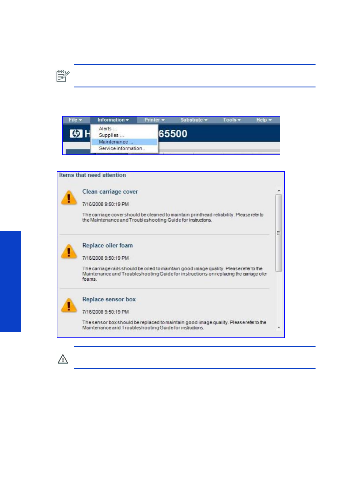
Operator maintenance alerts
The HP Internal Print Server displays alerts whenever a maintenance action is required. The following
seven alerts require action from the customer, and must be performed according to the life counter value
on the right (which is calculated into a percentage automatically).
For more information about these procedures, refer to the Maintenance and Troubleshooting Guide.
Alert Life Counter Value
Clean the Temperature Sensor 80 liters (see note 1)
Clean the Line Sensor 80 liters (see note 2)
Replace the Sensor Box No limit
Replace the oil reservoirs 6250 square meters (see note 3)
Clean the carriage rails 37501 square meters (see note 4)
Clean the carriage cover 80 liters (see note 5)
Clean the ink deposits 136 liters (see note 6)
Note 1: The corresponding counter in not visible in the service plot, but can be calculated from the
preventive maintenance chapter, by applying, at the line 'heating sensor', the column 'capacity'*'current
usage'.
Note 2: The corresponding counter is available in the service plot, in the component usage section, Line
sensor since last clean (milliliters) with a corresponding threshold: 80 000 000 (80l), number reported
with 000 more than ml.
Note 3: The corresponding counter is available in the service plot, in the component usage section: Usage
oil reservoir (m), with a corresponding limit of 500 000 m (500km of the carriage movement distance).
(Values are Approximate)
Preventative Maintenance
Note 4: The corresponding counter is available in the service plot, in the component usage section: Usage
slider rods (m), with a corresponding limit of 3 000 000 m (3000km of the carriage movement distance).
Note 5: The corresponding counter is available in the service plot, in the component usage section,
Carriage lid usage (milliliters), with a corresponding threshold: 80 000 000 (80l), number reported with
000 more than ml.
Note 6: The corresponding counter is available in the service plot, in the component usage section, Ink
deposit level (cc) , with a corresponding threshold: 136 000 (136l).
Preventive Maintenance 781
Page 4
Check for alerts
You can check the maintenance usage levels on the HP Internal Print Server, which are automatically
converted to a percentage according to the life counter values.
NOTE: You can also check the maintenance usage levels or life counters for individual
components using the Reset Life Counters utilitySee page 420.
To check the maintenance usage levels on the HP Internal Print Server, use the following procedure.
1. From the HP Internal Print Server, navigate to Information > Alerts.
2. The HP Internal Print Server displays the current alerts.
Preventative Maintenance
WARNING!: These percentages are estimations only.
782 Preventive Maintenance
Page 5

Check the maintenance usage levels on the HP Internal Print Server
You can check the maintenance usage levels on the HP Internal Print Server, which are automatically
converted to a percentage according to the life counter values.
NOTE: You can also check the maintenance usage levels or life counters for individual
components using the Reset Life Counters utilitySee page 420.
To check the maintenance usage levels on the HP Internal Print Server, use the following procedure.
1. From the HP Internal Print Server, navigate to Information > Maintenance.
2. The HP Internal Print Server displays the maintenance usage levels.
Preventive Maintenance 783
Preventative Maintenance
Page 6

Preventive maintenance service procedures
When a preventive maintenance number is displayed, before dispatching the part, a check is required to
see if there are no other preventive maintenance alerts which are about to be displayed. If there is another
maintenance about to be performed (another percentage of a calibration to be done by service for
example), propose to the customer to do the other one.
This can be done by asking the customer to send the service plot, and check the section preventive
maintenance section.
Conversion preventive maintenance # <-> name on service plot
1 <-> Curing Lamps Heating Lamps
2 <-> Chain cycles
3 <-> Ids buffer number of cycles
4 <-> Pps Cycles
5 <-> Tubes Cycles
Remember for the preventive maintenance 5 this has to be done only if the printer S/N less than
SG94S1F001 and that the tubes have not been already replaced.
Preventative Maintenance
How to know the equivalent remaining qty of ink / media before the preventive maintenance is
displayed?(100%-percentage)*capacity (from the preventative maintenance Usage part of the service
plot). This information is available within the IPS, maintenance status.
Preventive maintenance #1: Clean heating/curing module reflectors
For preventive maintenance, the Heating and Curing Module Reflectors must be cleaned in the following
circumstances:
• Whenever the service maintenance alert for Preventive Maintenance # 1 appears.
Service Part: Preventive Maintenance Kit #1
No service part is needed.
784 Preventive Maintenance
Page 7

Procedure
WARNING!: Make sure that people are clear from the printer and that it is safe to perform
the procedure.
1. Unload the Substrate if one is loaded.
2. Navigate to Substrate Management > Carriage Beam Height > Move to Highest Position.
3. Switch off the printer.
4. If the heating and curing modules are still hot, allow them to cool down.
WARNING!: Allow the system to cool down if it is hot. Working near the heating and curing
system while it is hot is dangerous and can cause burns.
5. Remove the eight T10 screws that secure each of the three curing module protection nets and remove
them.
NOTE: For each protection net, four of the screws must be removed from the front and four
from the back.
6. Clean the three reflectors in the curing modules,from the bottom side of the machine, with a lint free cloth
and isopropyl alcohol. You do not need to remove or clean the resistors.
7. Remove the six Torx screws that secure the heating system.
8. Raise the heating system.
Preventative Maintenance
Preventive Maintenance 785
Page 8

9. Remove the eight T10 screws that secure each of the three protection nets and remove them.
10. Clean the three reflectors with a lint free cloth and isopropyl alcohol. You do not need to remove or clean
the resistors.
NOTE: It is very important to reset the maintenance kit usage each time you perform
preventive maintenance action See
page 420.
Preventive maintenance #2: Replace the Carriage Chain Assembly
For preventive maintenance, the Carriage Chain Assembly must be replaced in the following
circumstances:
• Whenever the service maintenance alert for Preventive Maintenance # 2 appears.
Service Part: Preventive Maintenance Kit #2
• Carriage Chain Assembly PN # Q6702-60484
• 2 Ink Pressure Sensors PN # Q6702-60424
Procedure
For the replacement procedure for the Carriage Chain Assembly and Ink Pressure Sensors See page
631.
NOTE: It is very important to reset the maintenance kit usage each time you perform
preventive maintenance action See page 420.
Preventative Maintenance
Preventive maintenance #3: Replace the Intermediate Tank Set
The Intermediate Tank Sets must be replaced in the following circumstances:
• Whenever the service maintenance alert for Preventive Maintenance # 3 appears.
NOTE: Under these conditions, all of the Intermediate Tank Sets must be replaced at the
same time.
NOTE: When a broken bag is detected and the Intermediate Tank Sets have been installed
for less than one year, it is only necessary to replace the damaged Intermediate Tank Sets
(both tanks for that color)
page 321.
786 Preventive Maintenance
Page 9

Service Part: Preventive Maintenance Kit #3
• Intermediate Tank Set PN # Q6702-60432
Procedure
1. Clean the ventilation filter foams of the E-Cabinet page 789.
2. Clean the encoder reader on the carriage with a cloth and alcohol Isopropyl.
3. For the replacement procedure for the Intermediate Tank Sets, see page 324.
NOTE: It is very important to reset the maintenance kit usage each time you perform
preventive maintenance action See
page 420.
Preventive maintenance #4: Grease the PPS Screw Assembly
You must grease the PPS Screw Assembly in the following circumstances:
• Whenever the service maintenance alert for Preventive Maintenance # 4 appears.
• Whenever you replace the PPS Screw Assembly.
Service Part: Preventive Maintenance Kit #4
• Grease Kit PN # Q6702-60546
Procedure
1. Navigate to Carriage Beam Position > Move to Highest Position.
2. Put on the gloves and put some grease on your finger.
3. Apply the grease on the exposed, middle part of the PPS Screw by moving your finger up and down the
PPS Screw, filling the threads with grease. Continue applying the grease until the whole middle section of
the screw, all the way around the screw, is greased.
NOTE: You do not need to put grease on the outside of the threads.
NOTE: You do not need to put grease on the bottom or top of the screw. Moving the
mechanism up and down the screw is sufficient.
4. Repeat step 3 for each PPS Screw.
5. Return to the Carriage Beam Position menu and select Move to Printing (Normal) to move the car-
riage beam height back to the normal position and spread the grease.
6. Return to the Carriage Beam Position menu and select Move to Highest Position to move the carriage
beam height back to the highest position and spread the grease.
7. Repeat steps 5 and 6 two more times to fully spread the grease.
8. Remove any extra grease.
Preventative Maintenance
9. Make sure that the PPS Low Switch does not have any grease that will prevent it from working correctly. If
grease is interfering with the switch, remove it and gently clean the grease from the switch.
10. Clean the encoder reader on the carriage, with a cloth and alcohol Isopropyl.
11 . For the replacement procedure for the Intermediate Tank Sets, see page 324.
Preventive Maintenance 787
Page 10

12 . Return to the Carriage Beam Position menu and select Move to Printing (Normal) to move the car-
riage beam height back to the normal position.
NOTE: It is very important to reset the maintenance kit usage each time you perform
preventive maintenance action See
page 420.
Preventive maintenance #5: Replace Ink Tubes
The following parts must be dispatched to the customer for installation by an onsite engineer: Q670267011 (tube kit) and Q6702-60690 (Tubes Cleaning Kit)
The tubes replacement procedure can be found on page 693.
Preventative Maintenance
788 Preventive Maintenance
Page 11

Cleaning the ventilation filter foams of the E-Cabinet
Left side
ventilation fan
Right side
ventilation fan
It is important that the E-Cabinet is correctly ventalated, and so part of the maintenance procedures is to
periodically clean the foam filters of the left and right E-Cabinet ventalation fans.
1. Remove the Right Cover Slide Door page 485.
2. Remove the Right Side Rear Panel page 485.
3. There are two ventilation fans for he E-Cabinet; on the Left and Right.
Preventive Maintenance 789
Preventative Maintenance
Page 12

4. On each of the fans remove the plastic holding frame by unclipping it, this will expose the filter and fan.
5. Use the the compressed air gun (the one used to inflate the spindle), to blow dust and dirt from the filter
and fan.
Preventative Maintenance
790 Preventive Maintenance
 Loading...