

Page 1

8 Remote Support
• Callme@HP Configuration .................................................................................. 792
• Installation................................................................................................. 792
• Troubleshooting the setup ............................................................................ 793
• Callme@HP Operation....................................................................................... 794
• How to launch a call from Customer Printer.................................................... 794
• How to access a call from the Customer ........................................................ 794
• How to receive a file from a customer............................................................ 795
• How to Video stream and make snapshots..................................................... 795
• How to initiate a Remote Connection ............................................................ 796
• How to terminate a call ............................................................................... 797
• How to look for an old service request .......................................................... 797
Remote Support
Safety 791
Page 2
Callme@HP Configuration
Installation
This information is also included in the Printer´s Installation guide.
During installation process, specific information must be introduced into the IPS preferences to correctly
route the Remote Support Calls to the Support Agent (HP or Authorized Service Provider approved to
provide this Remote Support Service).
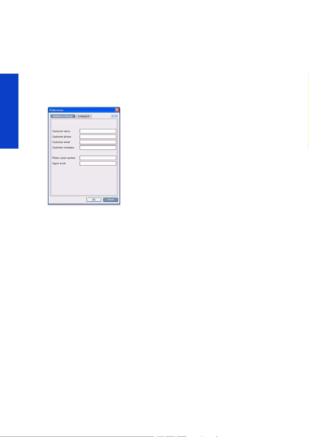
1. Go to the IPS menu “Tools”, then press “Preferences” and look for the tab “Callme@HP”.
Remote Support
2. Enter in information into all 6 fields:
The first four fields are related to customer data. They can be generic and are intended to be automatically
loaded as default data into the Remote Support Application.
a. Printer Serial Number: Check that the serial number is correctly entered into the text field.
b. Agent E-mail: This parameter is VERY important as it establishes the call routing to the
appropriate support organization. If the configuration of this field is not correct any support
calls made will not reach the intended recipient.
- If the Reseller partner is going to provide the support for the unit AND has been approved for
using this tool and has the account setup and permissions setup, enter in this field the E-mail
of the reseller engineer supporting this printer, using the reseller's domain used for creating
the account.
- If the reseller is not entitled to use the “Callme@hp” remote troubleshooting tool, then leave
the default value: printcare@hp.com.
3. Launch the “callme@HP” application under the “tools” menu option and verify the information entered
loads correctly into the template.
Important: The application will ask for software to be installed, select yes to all the requirements.
If no window is displayed, go to the Site Preparation document under the section where the network
requirements are described, and check that all the requirements for network connectivity have been met.
4. Submit a Testing Call including the following text in the comment box: “Customer Name Installation Call.
Remote Support Configuration Check”.
792
Page 3

Troubleshooting the setup
If after the Callme@HP software is installed the calls are not reaching the desired queue, verify that the
agent email field is correct. If the email address ends in ‘hp.com’ the call will be routed to the generic
GBU queue.
NOTE: If the agent is qualified to support the printer through the remote tool, the email can be different
from the default ‘printcare@hp.com’.
The reseller is qualified if the following is true
• The reseller has been trained to support the printer.
• An HP digital badge has been supplied.
• Access to ‘Callme@hp’.
• A reseller queue has been created
If the reseller queue has not been created and the agent’s email does not end in ‘hp.com’, the call will be
sent to an incorrect queue and the call will be lost.
Remote Support
Safety 793
Page 4
Callme@HP Operation
How to launch a call from Customer Printer
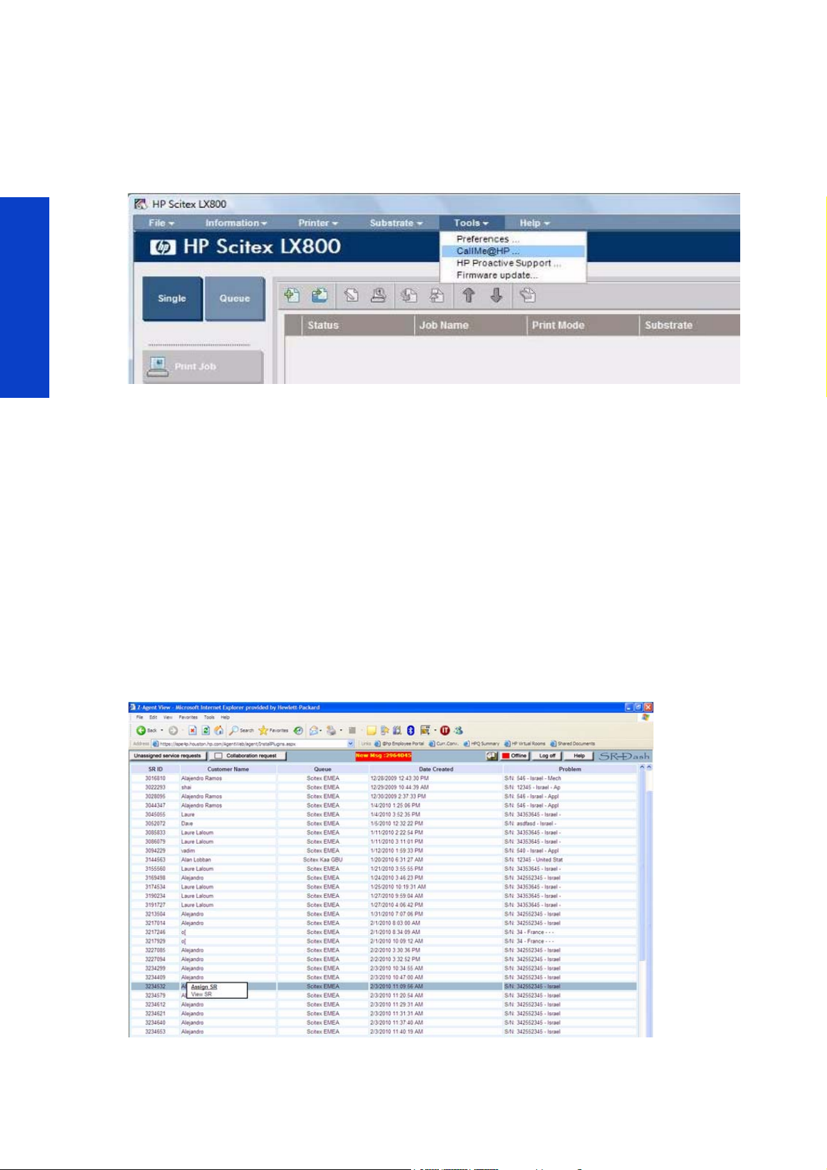
1. Go to the Callme@HP option in the “Tools” drop-down menu in the IPS.
Remote Support
2. Accept all requirements to install additional software.
3. If correctly configured, the web page will open with all parameters filled. Special attention should be
made to the Agent e-mail option. The mail domain MUST match the Reseller Domain (“@hp.com” for HP
direct supported units). If not correctly configured, please go to the appropriate chapter in the installation
guide.
4. HP agents have access to all reseller queues. There is no need to modify parameters. In second level esca-
lations, use the reseller queue.
5. Please make sure the customer fills in correctly the comments field with the issue description.
6. Press the ‘Accept’ button.
How to access a call from the Customer
1. Login to Callme@Hp page: https://ispe4p.houston.hp.com/AgentWeb/login.aspx
2. After login, identify the corresponding call from the list and select “Assign SR”.
794
Page 5
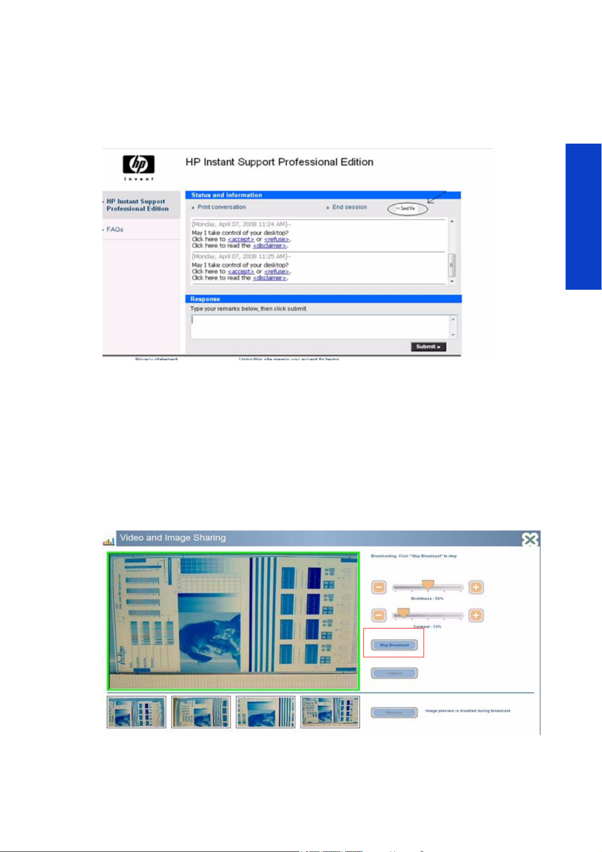
How to receive a file from a customer
To receive files go to the Callme@HP customer screen, ask the customer to select the “send file” option,
or do it yourself in a Remote IPS PC Control session. Browse the IPS PC folders and select the files.
On each Remote Troubleshooting Session, always capture the Service Plot and send to the HP Division
Customer Assurance contact.
Remote Support
How to Video stream and make snapshots
Video Streaming
LX Series printers come equipped with an HP Web Cam and 5m of USB extension cable.
1. Connect the USB extension cable to the IPS PC and the web cam to the USB extension cable.
2. Click on the ‘video’ tab in the Callme@HP tool.
3. The customer must start the ‘Print Care Webcam’ application in ‘Start> All Programs’
4. Customer must select ‘Start Broadcast’.
5. The HP Support engineer must select ‘Receive video’. A video screen will open and after a few seconds it
will start to buffer the video.
Safety 795
Page 6
• Note that there is around 5 seconds of delay on the video.
• Avoid video streaming and using the remote IPS PC at same time.
• To reinstall the camera software refer to page 775.
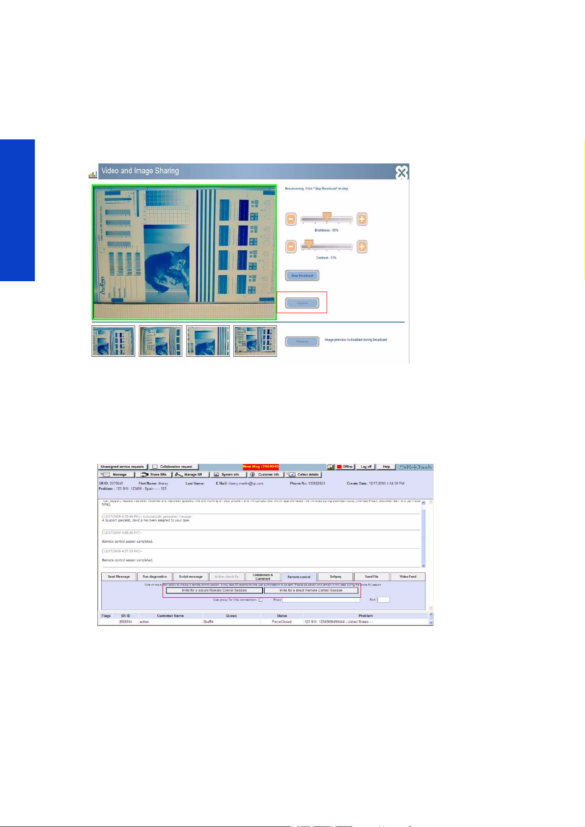
Taking snapshots
1. With the ‘Print Care Webcam’ tool activated, select the ‘Capture’ button.
2. Images can be seen in the small windows below Web Cam display.
Remote Support
3. You can transfer the pictures through the ‘send file option’. The snapshots are placed in the following path:
C:\Program Files\PrintCare\webcam\images.
How to initiate a Remote Connection
1. Login to Callme@Hp page: https://ispe4p.houston.hp.com/AgentWeb/login.aspx.
2. Select ‘Invite for a secure remote control session’ or ‘Invite for a direct remote control session’, depending
on the level of security required.
3. The customer must accept the remote connection on the chat screen.
796
Page 7
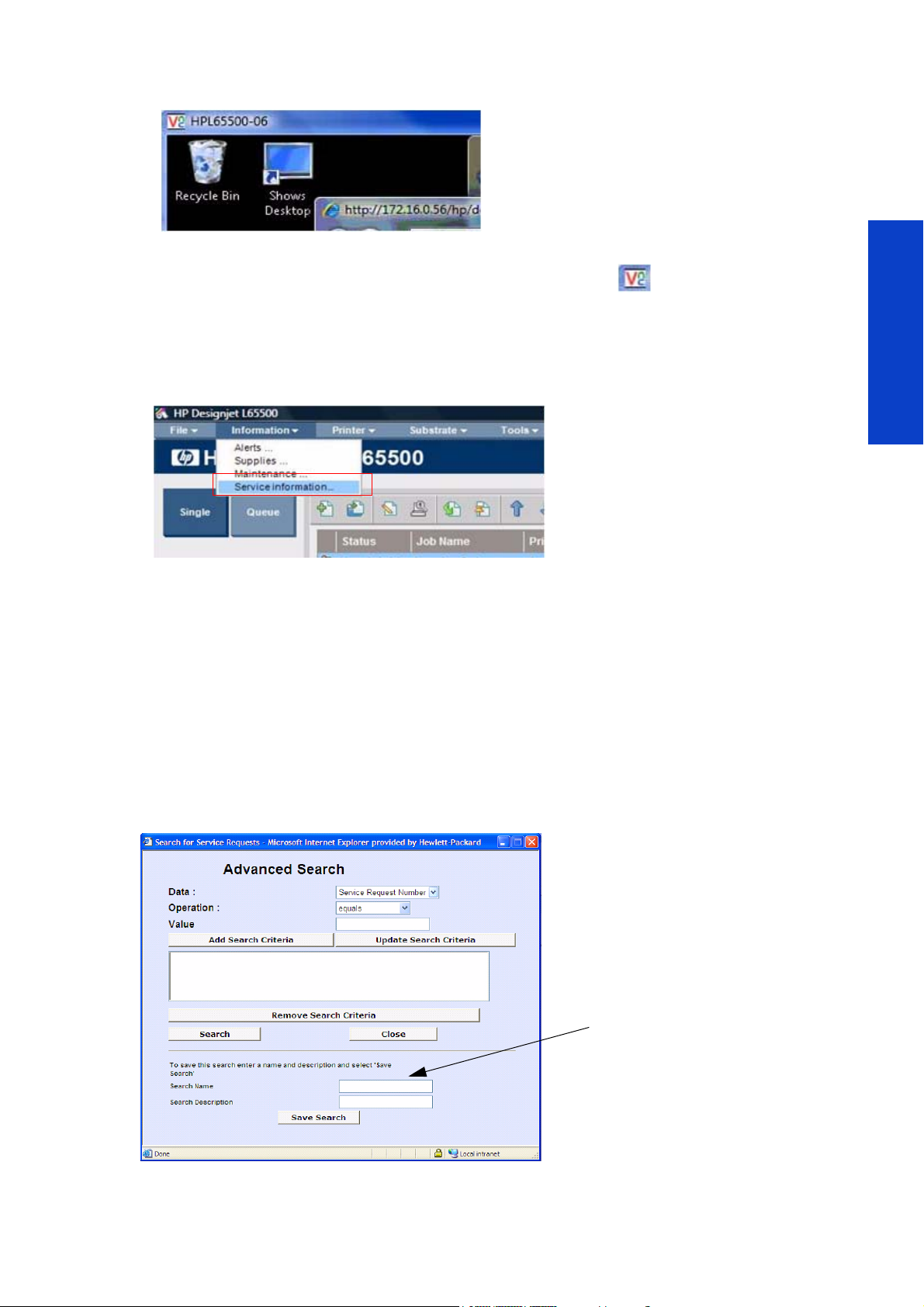
4. Once a remote session has started the customer’s IPS PC can be seen through window with VNC logo.
2. Select the search criteria, we recom-
mend by:
•By SR Queue
•By Queue name
•By Date
TIP: The most common searches can
be saved for later use.
5. The customer can see the VNC icon at the bottom right of the screen.
How to view the Service Plot via a Remote Connection
1. From the IPS, click on Information -> Service information and an internet explorer window is opened with
the service plot.
Remote Support
2. The customer must accept the remote connection.
3. A copy of the service plot is placed on the desktop under folder ‘Service information’.
4. Always capture the service plot and send to the HP Division Customer Assurance contact.
How to terminate a call
The Customer can cut the remote control at any time by right-clicking on the VNC icon, and selecting ‘stop
session’. The remote support engineer can terminate the session by closing the VNC window.
How to look for an old service request
1. In the HP Support application, go to ‘Advance Search’.
Safety 797
Page 8

Remote Support
798
Page 9

9 Move the printer
• Related documents ........................................................................................... 800
• Moving the printer to the same site (no ramps, no steps).........................................801
• Moving the printer to the same site (with ramps or steps) ....................................... 802
• Moving the printer to a new site (transport temperature more than 5C/41F) ............. 806
• Moving the printer to a new site (transport temperature below 5C/41F).................... 816
Move the printer 799
Moving the Printer
Page 10

Related documents
• Site Preparation Guide
• Installation Guide
Moving the Printer
800 Move the printer
Page 11

Moving the printer to the same site (no ramps, no
steps)
If you wish to move the printer a short distance on the same site, across a horizontal floor with no steps
and no slopes, see the following instructions.
• To prepare the new installation site, see the Site Preparation Guide.
• Unmount and reinstall the printer, use the Installation Guide as a reference.
Procedure
1. Turn off the printer.
2. Disconnect all power and network cables from the printer.
3. Raise the feet so that the wheels (A) touch the ground. To raise a foot:
a. Use a 30 mm wrench to unlock the nut at the top of the foot.
b. Rotate the nut manually down the bolt. Leave about 2 cm (0.8 in) clearance at the bottom
between nut and foot.
c. Use a 15 mm wrench to rotate the foot upwards. Use the flat faces at the bottom of the bolt to
fit the wrench.
d. Raise the foot as far as the bolt allows.
e. Use the 30 mm wrench to relock the nut.
CAUTION: Take care to raise the feet as high as you can. They may break if they touch the ground
while the printer is in motion.
4. Push the printer from the outside corners of the top covers.
After moving the printer, you may in some cases need an electrician to reconnect the power cables. You
may also need to reconfigure the network: from the front panel, from the HP Internal Print Server computer,
and from the RIP computer. See the Installation Guide for more details.
Moving the Printer
Move the printer 801
Page 12

Moving the printer to the same site (with ramps or
steps)
If you need to move the printer within the same site but their are ramps or steps on the route, you will need
to lift the printer with a forklift or a crane
Some preparations must be made before the printer can be lifted (listed below), and failure to follow these
steps could cause irreversible damage to the printer.
Procedure
1. Check the Site Preparation Guide to make sure that the new site is well-prepared. For more details on
each procedure refer to the installation guide.
2. Turn off the printer.
3. Reboot the printer in diagnostic boot mode and '4.13: Force fill the intermediate ink tanks’ to prevent
broken bags, see
4. Disconnect the 3 phase and single phase power supply.
5. Remove the printheads and store them in their original caps.
6. Remove the two aerosol filters.
7. Remove the ink cartridges and store them in their initial packaging.
page 330'.
8. Remove the Printhead Cleaner Roll. You can cut the material, removing the used material of the lower
core, but important: KEEP THE LOWER COVER (can remove the used material around this core).
9. Remove the HP Internal Print Server and switch.
10. Remove the monitor, keyboard, mouse, and keyboard platform See page 505.
11 . Remove the Left Side Front Cover and Left Side Rear Cover See page 483.
12 . Force fill the intermediate ink tanks to prevent broken bagsSee page 339.
13 . Gently remove the intermediate ink tanks without shaking them.
Moving the Printer
14 . Remove the Right Side Rear Cover See page 485.
15 . Open the sliding door.
802 Move the printer
Page 13

16 . Secure the carriage in the travel position with the T25 screw.
Graphics taken from Installation Guide. For reference only.
17. Secure the scan axis to the printer chassis with the eight T20 screws.
Graphics taken from Installation Guide. For reference only.
Move the printer 803
Moving the Printer
Page 14

18 . Secure the Printhead Cleaning Assembly with two T20 screws.
Pass the strap under the printer frame
19. Secure the electrical cabinet with the strap.
NOTE: Make two loops if possible. The strap should be loose or have very little tension
during transportation.
Moving the Printer
20. The ISM must be secured with a strap.
804 Move the printer
Page 15

21. You can now lift the printer with a forklift, pallet jack, or crane using the forklift guides in the middle of the
printer. Use the recommendations in the Site Preparation Guide and Installation Guide.
Move the printer 805
Moving the Printer
Page 16

Moving the printer to a new site (transport
temperature more than 5C/41F)
If you need to move the printer to a new site, the printer must be fixed to a pallet. If the temperature will
not drop below 5° C/41° F, follow these instructions. Failure to follow these instructions could cause the
ink to freeze, which would damage the ink system and require heavy repair.
Procedure
1. The following steps are the main steps, refer to the installation guide (in reverse order) for a more detailed
explanation.
2. Lift the printer with a forklift, pallet jack, or crane, following the instructions in the Site Preparation Guide
and Installation Guide.
3. Remove the four bolts that secure the foot blocks to the pallet (16 total) and remove them.
4. To attach the foot block to the printer foot, remove the nut and washer.
5. Position the block and replace the nut and washer so that it is attached to the printer foot.
Moving the Printer
806 Move the printer
Page 17

6. Fix the two E-Cabinet Cushion Holders onto the right side of the shipping pallet.
Right side
Cushion holder
Long Tray
Short Tray
Short Tray
Long Tray
180
300
240
340
530
200
Front
Rear
7. Install four ISM Supports into the two ISM Support Trays (long and short).
8. Install ISM Supports and Trays onto the right side of the shipping pallet at the following dimensions:
9. Add new info from Excel sheet here (page 6 -7-9-10-11-12-13-15-19 and bottom line drawing page 21, 24,
blue shrink wrap picture on 25
Move the printer 807
Moving the Printer
Page 18

10. Place the forklift underneath the printer and make sure that the forks on the forklift are spaced 80 cm
apart (A). Place the printer on the pallet, and secure it with the four 24 mm nuts.
11 . Secure each foot block with the four bolts removed with the block earlier.
Moving the Printer
808 Move the printer
Page 19

12. Place tape around the Cusion holders as shown here:
13 . Secure the Inbox onto the pallet.
14 . Ensure the Inbox is secured between the ISM and the lifting bracket.
Moving the Printer
Move the printer 809
Page 20

15 . Ensure that the box with the PC inside in an upright position and secured the with strapping. Place next to
Important: The PC Box must be in an
uprigtht position
Use straapping to secure the covers (but not too tight)
Covers in wrapping
Secure support
foams herewith tape
Place the ID cover
box here
the Inbox
16 . L65500/LX600 only: Place the ID Covers on to the pallet on the right side of the E-Cabinet.
.
17. LX800 only: Place the ID Covers in their box and secure with strapping. Place onto the pallet at the rear
(close to the E-Cabinet).
Moving the Printer
810 Move the printer
Page 21

18 . LX800 only: Place the Gutter Assembly in the box, and place on the pallet next to the PC box
Gutter Assmbly
U-shaped foam block
Plywood Top clamp
Media Drive Input spindle
19. Secure the Media Drive Input spindle onto the pallet using two U-shaped foam blocks and Plywood Top
Clamps.
20. LX800 only: Assembly the clamps and supports on the left and right of the pallet (front).
Move the printer 811
Moving the Printer
Page 22

21. LX800 only: Install the two Dual Rolls onto the foam supports, and clamp the rolls in place with the Ply-
Ensure that the differentials of the two dual
rolls are placed at either ends of the spindles
to give balance
wood clamps.
22. LX800 only: Tighten the locking screws of the differentials and tape the wrench keys to the spindles.
Moving the Printer
23. LX800 only: Remove the End Caps of the Dual Rolls as they can cause damge to the side plates. Place
the End Caps in the Inbox
24. LX800 only: Add another layer of foam supports on top the the existing foam supports (see above).
812 Move the printer
Page 23

25. LX800 only: Install the two Wrinkle Deflectors onto the foam supports, and place foam stoppers ot
Foam stopper
Media Drive Input
Spindle
Plywood clamp
each end.
26. LX800 only: Install the Media Drive Input spindle into the foam supports and clamp in place with the
Plywood Clamps.
27. LX800 only: Install the Spindle Stoppers at both ends of the spindle.
Moving the Printer
Move the printer 813
Page 24

28. LX800 only: Install the Media Drive Output Spindle into the printer as per normal operation, and
secure it in place with a tie-wrap at both ends.
29. Wrap the complete printer with 3D VCI Bag as shown below. Make sure the printer is fully covered and is
sealed using packing tape.
30. If necessary, build the crate around the printer. You will need an electric screwdriver with a Philips head.
Moving the Printer
814 Move the printer
Page 25

31. Each panel is numbered, refer to the drawing below to help with assembling the panels.
2
8
1
5
6
4
12
7
3
10
11
9
32. Wrap the compete package with a plastic sheet.
33. Cover the package in heavy-duty wrapping and shrink-wrap.
Move the printer 815
Moving the Printer
Page 26

Moving the printer to a new site (transport
temperature below 5C/41F)
In this case, before switching off the printer, the ink must be removed from the tubes. You need to have
the ink system cleaning tubes and 5 liter of distilled water.
The procedure below shows how remove the ink from one line of color. This operation must be repeated
5 times (total of 5 hours).
ISM Flush and clean a single ink system line
Flushing the ink lines with distilled water and then with air removes the ink from the tubes, this enables you to remove
and replace parts of the ink system. The flushing procedure is done one ink line at a time.
1. Remove the printheads and store them in their caps.
2. Remove the Left Side Front Panel See page 483.
3. Remove the Left Side Rear Panel See page 483.
4. Remove the Left Side Lateral Panel See page 483.
5.Remove the Ink Cartridge.
Moving the Printer
6.Carefully remove the intermediate tanks of the color you are
going to flush
.
NOTE: Store the intermediate ink tanks vertically.
Failure to store them vertically can cause a broken
bag.
816 Move the printer
Page 27

7. Place the Flushing Tool in the space left when the ink cartridge
was removed, and connect the ink connector to the connection
port of the tool.
8. Connect cable from the Flushing Tool to J18 on the ISM Board.
9. From the Front Panel go to the Diagnostic Menu and select Ink System Menu 4.0>Flushing procedure>Activate
Flushing tool Pump.
10. Open the Entry Electrovalve of the color you are flushing Ink System Menu 4.0>Flushing procedure>Operate
Entry electrovalve-> “Color to flush”.
11 . Unscrew the top of the Cleaning Tool and fill the bottle with 500cc of distilled water.
12. Insert a needle into the tube coming from a waste bottle
13 . Insert the needle into the Printhead Ink Connector of the
Carriage assembly. Ensure you insert it into the correct color.
Moving the Printer
Move the printer 817
Page 28

14 . Ensure the path switch is in the horizontal position.
15 . Turn On the Flushing Tool with the switch located on top.
The Cleaning Tool slowly pumps the distilled water into the tubes and ink system of the color you are cleaning.
The pumping action cleans ink out of the tubes and into the draining bottle.
16 . When the level of distilled water is half finished:
a.Install the New Empty Intermediate Flushing Tank (that came
with the flushing kit) into the Left Intermediate slot, wait 10 sec
onds for the ink to be cleaned from this area and then remove
the tank.
-
b.Install the Intermediate Flushing Tank into the Right Intermedi-
ate slot, wait 10 seconds for the ink to be cleaned from this area
and then remove the tank.
NOTE: If the distilled water in the Cleaning
Tool bottle becomes low before the ink system
has been cleaned of ink, you must refill the
bottle with more water. You must stop the
Flushing tool to add more water.
17. When the Ink system has been cleaned of ink and the Flushing tool becomes empty of water, the pump of the
Cleaning Tool will then push air into the ink system tubes, which will push the water out into the draining
bottle of the Quick Connector Flushing Tool, this process will last for approximately 5 minutes.
18 . When five minutes has past:
a.Install the Intermediate Flushing Tank (that came with the flush-
Moving the Printer
ing kit) into the Left Intermediate slot, wait 10 seconds for the
water to be removed from this area and then remove the tank.
b.Install the Intermediate Flushing Tank into the Right Intermedi-
ate slot, wait 10 seconds for the water to be removed from this
area and then remove the tank.
19. When the Ink system has been cleaned of ink and the
Flushing tool becomes empty of water, the pump of the
Cleaning Tool will then push air into the ink system tubes, which
will push the water out into the draining bottle of the Quick Connector Flushing Tool, this process will last for
approximately 5 minutes.
818 Move the printer
 Loading...