

Page 1
Service Manual
Page 2

Page 3

HP Color LaserJet CP2020 Series
Service Manual
Page 4

Copyright information
Safety information
Trademark credits
© 2008 Copyright Hewlett-Packard
Development Company, L.P.
Reproduction, adaptation, or translation
without prior written permission is prohibited,
except as allowed under the copyright laws.
The information contained herein is subject
to change without notice.
The only warranties for HP products and
services are set forth in the express warranty
statements accompanying such products
and services. Nothing herein should be
construed as constituting an additional
warranty. HP shall not be liable for technical
or editorial errors or omissions contained
herein.
Part number CB493-90948
Edition 1, 09/2008
WARNING!
Potential Shock Hazard
Always follow basic safety precautions when
using the product to reduce risk of injury from
fire or electric shock.
Read and understand all instructions in the
user guide.
Observe all warnings and instructions
marked on the product.
Use only a grounded electrical outlet when
connecting the product to a power source. If
you do not know whether the outlet is
grounded, check with a qualified electrician.
Do not touch the contacts on the end of any
of the sockets on the product. Replace
damaged cords immediately.
Unplug the product from wall outlets before
cleaning.
Do not install or use the product near water
or when you are wet.
Install the product securely on a stable
surface.
Microsoft® and Windows® are U.S.
registered trademarks of Microsoft
Corporation.
Windows Vista® is either a registered
trademark or trademark of Microsoft
Corporation in the United States and/or other
countries or regions.
Linux is a U.S. registered trademark of Linus
Torvalds.
UNIX® is a registered trademark of The
Open Group.
PostScript® is a trademark of Adobe
Systems Incorporated.
ENERGY STAR and the ENERGY STAR
mark are registered U.S. marks.
Install the product in a protected place where
no one can step on or trip over the power
cord and where the power cord will not be
damaged.
If the product does not operate normally, see
the online user guide.
Refer all servicing questions to qualified
personnel.
Information regarding FCC Class B, Parts 15
and 68 requirements can be found in the user
guide.
Page 5

Table of contents
1 Product basics
Quick access to product information .................................................................................................... 2
Product comparison ............................................................................................................................. 3
Product features ................................................................................................................................... 3
Walkaround .......................................................................................................................................... 4
Front and side view .............................................................................................................. 4
Back view ............................................................................................................................. 5
Model and serial numbers ................................................................................................... 5
Supported operating systems ............................................................................................................... 6
Supported product software ................................................................................................................. 7
Software included with the product ...................................................................................... 7
Recommended Installation for Windows ............................................................. 7
Express Installation ............................................................................................. 7
Macintosh software ............................................................................................. 7
Printer driver ........................................................................................................................ 7
Other software provided ...................................................................................................... 8
Software for Windows ......................................................................................... 8
HP ToolboxFX .................................................................................... 8
Software for Macintosh ....................................................................................... 8
PostScript Printer Description (PPD) files .......................................... 8
Configure the product using a Macintosh ........................................... 8
Status Alerts software ......................................................................................... 8
Software for networks ......................................................................................... 8
HP Web Jetadmin ............................................................................... 8
Embedded Web server ....................................................................... 9
Linux ................................................................................................... 9
System requirements ........................................................................................................... 9
Windows requirements ........................................................................................ 9
Macintosh requirements ...................................................................................... 9
Connectivity ........................................................................................................................................ 10
Supported network operating systems .............................................................................. 10
Printer sharing disclaimer .................................................................................. 10
Supported network protocols ............................................................................................. 10
ENWW iii
Page 6

2 Control panel
Control-panel walkaround .................................................................................................................. 14
Control-panel menus .......................................................................................................................... 15
Use the menus ................................................................................................................... 15
Reports menu .................................................................................................................... 16
System setup menu ........................................................................................................... 17
Service menu ..................................................................................................................... 19
Network config. menu ........................................................................................................ 20
3 Paper and print media
Understand paper and print media use .............................................................................................. 22
Supported paper and print media sizes .............................................................................................. 23
Supported paper types and tray capacity ........................................................................................... 25
Special paper or print media guidelines ............................................................................................. 27
Load paper and print media ............................................................................................................... 28
4 Manage and maintain
Information pages ............................................................................................................................... 32
HP ToolboxFX .................................................................................................................................... 33
Open HP ToolboxFX .......................................................................................................... 33
Status ................................................................................................................................. 33
Alerts .................................................................................................................................. 34
Product information ............................................................................................................ 34
Set password ..................................................................................................................... 34
Help ................................................................................................................................... 35
Device Settings .................................................................................................................. 36
Network Settings ................................................................................................................ 39
Shop for Supplies .............................................................................................................. 39
Event log ........................................................................................................... 33
Set up Status Alerts .......................................................................................... 34
Set up E-mail Alerts .......................................................................................... 34
Device Information ............................................................................................ 36
Paper Handling ................................................................................................. 37
Printing .............................................................................................................. 37
PCL5c ............................................................................................................... 37
PostScript .......................................................................................................... 37
Print Quality ....................................................................................................... 38
Print Density ...................................................................................................... 38
Paper Types ...................................................................................................... 38
System Setup .................................................................................................... 38
Save/Restore Settings ...................................................................................... 38
Password .......................................................................................................... 38
Service .............................................................................................................. 39
iv ENWW
Page 7

Other Links ........................................................................................................................ 39
Embedded Web server ....................................................................................................................... 40
View the HP embedded Web server .................................................................................. 40
Embedded Web server sections ........................................................................................ 41
HP Web Jetadmin .............................................................................................................................. 43
Manage supplies ................................................................................................................................ 44
Supplies life ....................................................................................................................... 44
Print-cartridge storage ....................................................................................................... 44
HP policy on non-HP print cartridges ................................................................................. 44
HP fraud hotline and Web site ........................................................................................... 44
Print when cartridge is out ................................................................................................. 45
Replace print cartridges ..................................................................................................................... 46
Memory and font DIMMs .................................................................................................................... 50
Product memory ................................................................................................................ 50
Install memory and font DIMMs ......................................................................................... 50
Enable memory .................................................................................................................. 54
Enable memory for Windows ............................................................................ 54
Check DIMM installation .................................................................................................... 54
Clean the product ............................................................................................................................... 54
Firmware updates ............................................................................................................................... 55
5 Theory of operation
Basic operation ................................................................................................................................... 58
Major product systems ....................................................................................................... 58
Product components .......................................................................................................... 59
Sequence of operation ....................................................................................................... 60
Engine control system ........................................................................................................................ 61
DC controller ...................................................................................................................... 62
Low-voltage power supply ................................................................................................. 62
High-voltage power supply ................................................................................................ 63
Laser/scanner system ........................................................................................................................ 65
Laser failure detection ....................................................................................................... 65
Image-formation system ..................................................................................................................... 66
Image-formation process ................................................................................................... 66
Latent-image formation stage ............................................................................................ 67
Developing stage ............................................................................................................... 68
Transfer stage .................................................................................................................... 69
Step 1: primary charging ................................................................................... 67
Step 2: laser-beam exposure ............................................................................ 68
Step 3: development ......................................................................................... 68
Step 4: primary transfer ..................................................................................... 69
Step 5: secondary transfer ................................................................................ 69
Step 6: separation from the drum ...................................................................... 70
ENWW v
Page 8

Fusing stage ...................................................................................................................... 70
ITB cleaning stage ............................................................................................................. 71
Drum cleaning stage .......................................................................................................... 72
Pickup-and-feed system ..................................................................................................................... 73
Jam detection .................................................................................................................... 75
6 Removal and replacement
Removal and replacement strategy ................................................................................................... 78
General cautions during removal and replacement ........................................................... 78
Electrostatic discharge ....................................................................................................... 78
Required tools ................................................................................................................... 79
Types of screws ................................................................................................................. 79
Before performing service .................................................................................................. 80
After performing service ..................................................................................................... 80
Post-service test ................................................................................................................ 81
Print cartridges ................................................................................................................................... 82
Tray 2 cassette ................................................................................................................................... 83
Rollers and pads ................................................................................................................................ 84
Transfer roller .................................................................................................................... 84
Paper-pickup roller ............................................................................................................. 85
Separation roller ................................................................................................................ 87
Paper-pickup roller (Tray 1) ............................................................................................... 90
Separation pad (Tray 1) ..................................................................................................... 92
Components and major assemblies ................................................................................................... 93
Link guide .......................................................................................................................... 93
DIMM cover ....................................................................................................................... 94
Print-cartridge drawer ........................................................................................................ 95
Intermediate transfer belt (ITB) .......................................................................................... 97
Paper-feed guide assembly ............................................................................................. 101
Rear-door stopper and link caps (simplex product) ......................................................... 103
Rear door (simplex product) ............................................................................................ 104
Rear door (duplex product) .............................................................................................. 106
Right cover ....................................................................................................................... 108
Rear-upper cover (duplex product) .................................................................................. 111
Rear cover and feed guide (simplex product) .................................................................. 112
Rear-lower cover and rear-door links (duplex product) ................................................... 116
Step 7: fusing .................................................................................................... 70
Step 8: ITB cleaning .......................................................................................... 71
Step 9: drum cleaning ....................................................................................... 72
Print-quality test ................................................................................................ 81
Reinstall the separation roller ............................................................................ 89
Reinstall the ITB .............................................................................................. 100
Reinstall the right cover ................................................................................... 110
vi ENWW
Page 9

Rear-door rib assembly (duplex product) ........................................................................ 119
Upper-cover assembly ..................................................................................................... 121
Reinstall the upper cover ................................................................................ 123
Control-panel assembly ................................................................................................... 124
Left cover ......................................................................................................................... 126
Reinstall the left cover ..................................................................................... 127
High-voltage power-supply PCA ...................................................................................... 129
Color-misregistration sensor assembly PCA ................................................................... 132
Reinstall the color-misregistration sensor assembly ....................................... 135
Right panel ....................................................................................................................... 136
Motors (M1 and M2) ........................................................................................................ 140
DC controller PCA ........................................................................................................... 142
Special considerations .................................................................................... 142
Remove the DC controller PCA ...................................................................... 142
Formatter PCA ................................................................................................................. 144
Special considerations .................................................................................... 144
Remove the formatter PCA ............................................................................. 144
Fan ................................................................................................................................... 146
Intermediate PCA ............................................................................................................ 147
Right-front cover and power button ................................................................................. 148
Power-supply sub PCA .................................................................................................... 150
Fuser motor assembly ..................................................................................................... 154
Reinstall the fuser motor assembly ................................................................. 158
Duplex reverse-drive assembly ....................................................................................... 159
Fuser ................................................................................................................................ 162
Reinstall the fuser ........................................................................................... 167
Paper-delivery assembly ................................................................................................. 168
Front-door assembly ........................................................................................................ 171
Reinstall the front-door assembly .................................................................... 176
7 Problem solve
Introduction ....................................................................................................................................... 180
Solve problems checklist .................................................................................................................. 181
Menu map ........................................................................................................................................ 181
Troubleshooting process .................................................................................................................. 182
Pretroubleshooting checklist ........................................................................................... 182
Power-on checks ............................................................................................................. 184
Tools for troubleshooting .................................................................................................................. 185
Print-quality troubleshooting tools .................................................................................... 185
Calibrate the product ....................................................................................... 185
Problem-solve diagrams ................................................................................................................... 186
Repetitive image defects ................................................................................................. 186
Interface ports .................................................................................................................. 187
ENWW vii
Page 10

DC controller PCA ........................................................................................................... 188
Major components ........................................................................................................... 190
Solenoids, clutches, and sensors .................................................................................... 191
Rollers .............................................................................................................................. 192
Motors and fans ............................................................................................................... 193
PCAs ................................................................................................................................ 194
Timing diagram ................................................................................................................ 195
Circuit diagram ................................................................................................................. 195
Control-panel messages .................................................................................................................. 197
Pages and reports ............................................................................................................................ 201
Diagnostic page ............................................................................................................... 201
Configuration page .......................................................................................................... 201
Supplies status page ....................................................................................................... 201
Event log .......................................................................................................................... 202
Paper-handling problems ................................................................................................................. 204
Clear jams ........................................................................................................................ 204
Common causes of jams ................................................................................. 204
Jam locations .................................................................................................. 205
Change Jam Recovery setting ........................................................................ 205
Clear jams in Tray 1 ........................................................................................ 206
Clear jams in Tray 2 ....................................................................................... 208
Clear jams in Tray 3 ....................................................................................... 209
Clear jams in fuser area .................................................................................. 210
Clear jams in output bin .................................................................................. 211
Clear jams in duplexer (duplexing models only) ............................................. 212
Image defects ................................................................................................................................... 214
General print quality issues ............................................................................................. 214
Solve issues with color documents .................................................................................. 218
Solve connectivity problems ............................................................................................................. 220
Solve direct-connection problems .................................................................................... 220
Solve network problems .................................................................................................. 220
Service mode functions .................................................................................................................... 222
Service menu ................................................................................................................... 222
Service menu settings ..................................................................................... 222
Restore the factory-set defaults ...................................................................... 222
Secondary service menu ................................................................................................. 222
Open the secondary service menu ................................................................. 222
Secondary service menu structure .................................................................. 222
Engine resets ................................................................................................................... 224
Engine test page ............................................................................................. 224
Cold reset ........................................................................................................ 224
NVRAM initialization ........................................................................................ 225
Performance problems ..................................................................................................................... 226
Print speeds ..................................................................................................................... 227
viii ENWW
Page 11

8 Parts and diagrams
Order parts, accessories, and supplies ............................................................................................ 230
Order directly from HP ..................................................................................................... 230
Part numbers .................................................................................................................................... 230
Supplies ........................................................................................................................... 230
Memory ............................................................................................................................ 230
Cable and interface accessories ...................................................................................... 231
Paper-handling accessories ............................................................................................ 231
User-replaceable parts .................................................................................................... 231
Whole unit replacement ................................................................................................... 231
Screws .............................................................................................................................................. 232
How to use the parts lists and diagrams .......................................................................................... 233
External components ........................................................................................................................ 234
Covers, panels, and doors ............................................................................................... 234
Internal components ......................................................................................................................... 236
Internal components (1 of 7) ............................................................................................ 236
Internal components (2 of 7) ............................................................................................ 238
Internal components (3 of 7) ............................................................................................ 240
Internal components (4 of 7) ............................................................................................ 242
Internal components (5 of 7) ............................................................................................ 244
Internal components, simplex products (6 of 7) ............................................................... 246
Internal components, duplex products (7 of 7) ................................................................ 248
Major assemblies ............................................................................................................................. 250
Cassette (Tray 2) ............................................................................................................. 250
Fuser assembly ............................................................................................................... 252
PCAs ................................................................................................................................ 254
Optional 250-sheet paper cassette .................................................................................................. 256
Alphabetical parts list ....................................................................................................................... 258
Numerical parts list ........................................................................................................................... 261
Appendix A Service and support
Hewlett-Packard limited warranty statement .................................................................................... 266
Customer self repair warranty service .............................................................................................. 267
Print cartridge limited warranty statement ........................................................................................ 268
Customer support ............................................................................................................................. 269
Repack the product .......................................................................................................................... 270
Service information form .................................................................................................................. 271
Appendix B Specifications
Physical specifications ..................................................................................................................... 274
Electrical specifications .................................................................................................................... 275
Acoustic emissions ........................................................................................................................... 276
Environmental specifications ............................................................................................................ 276
ENWW ix
Page 12

Appendix C Regulatory information
FCC regulations ............................................................................................................................... 278
Declaration of conformity .................................................................................................................. 279
Safety statements ............................................................................................................................. 280
Laser safety ..................................................................................................................... 280
Canadian DOC regulations .............................................................................................. 280
VCCI statement (Japan) .................................................................................................. 280
Power cord statement (Japan) ......................................................................................... 280
EMC statement (Korea) ................................................................................................... 280
Laser statement for Finland ............................................................................................. 281
Substances Table (China) ............................................................................................... 282
Certificate of Volatility ...................................................................................................... 283
Types of memory ............................................................................................ 283
Volatile memory .............................................................................. 283
Non-volatile memory ....................................................................... 283
Index ................................................................................................................................................................. 285
x ENWW
Page 13

List of tables
Table 1-1 Product guides ................................................................................................................................... 2
Table 1-2 Printing ............................................................................................................................................. 10
Table 1-3 Network product discovery ............................................................................................................... 10
Table 1-4 Messaging and management ........................................................................................................... 10
Table 1-5 IP addressing ................................................................................................................................... 11
Table 3-1 Supported paper and print media sizes ........................................................................................... 23
Table 3-2 Supported envelopes and postcards ............................................................................................... 23
Table 3-3 Tray 1 ............................................................................................................................................... 25
Table 3-4 Tray 2 and Tray 3 ............................................................................................................................. 26
Table 5-1 Sequence of operation ..................................................................................................................... 60
Table 7-1 Repetitive image defects ................................................................................................................ 186
Table 7-2 DC controller connectors ................................................................................................................ 188
Table 7-3 Major components .......................................................................................................................... 190
Table 7-4 Solenoid, clutches, and sensors .................................................................................................... 191
Table 7-5 Rollers ............................................................................................................................................ 192
Table 7-6 PCAs ............................................................................................................................................. 194
Table 7-7 Event-log messages ....................................................................................................................... 202
Table 7-8 2ndary Service menu ..................................................................................................................... 222
Table 8-1 Common fasteners ........................................................................................................................ 232
Table 8-2 Covers, panels, and doors ............................................................................................................. 235
Table 8-3 Internal components (1 of 7) .......................................................................................................... 237
Table 8-4 Internal components (2 of 7) .......................................................................................................... 239
Table 8-5 Internal components (3 of 7) .......................................................................................................... 241
Table 8-6 Internal components (4 of 7) .......................................................................................................... 243
Table 8-7 Internal components (5 of 7) .......................................................................................................... 245
Table 8-8 Internal components, simplex products (6 of 7) ............................................................................. 247
Table 8-9 Internal components, duplex products (7 of 7) ............................................................................... 249
Table 8-10 Cassette (Tray 2) ......................................................................................................................... 251
Table 8-11 Fuser assembly ............................................................................................................................ 253
Table 8-12 PCAs ............................................................................................................................................ 255
Table 8-13 250-sheet paper cassette ............................................................................................................ 257
Table 8-14 Alphabetical parts list ................................................................................................................... 258
Table 8-15 Numerical parts list ....................................................................................................................... 261
Table B-1 Physical specifications ................................................................................................................... 274
ENWW xi
Page 14

Table B-2 Electrical specifications .................................................................................................................. 275
Table B-3 Power consumption (average, in watts), ....................................................................................... 275
Table B-4 HP Color LaserJet CP2020 Series, ............................................................................................... 276
Table B-5 Operating-environment specifications ........................................................................................... 276
xii ENWW
Page 15

List of figures
Figure 5-1 Product systems ............................................................................................................................. 58
Figure 5-2 Product components ....................................................................................................................... 59
Figure 5-3 Engine control system components ................................................................................................ 61
Figure 5-4 DC controller circuit diagram ........................................................................................................... 62
Figure 5-5 Low-voltage power supply .............................................................................................................. 63
Figure 5-6 High-voltage power supply .............................................................................................................. 64
Figure 5-7 Laser/scanner system ..................................................................................................................... 65
Figure 5-8 Image-formation system ................................................................................................................. 66
Figure 5-9 Image-formation process ................................................................................................................ 67
Figure 5-10 Primary charging ........................................................................................................................... 67
Figure 5-11 Laser-beam exposure ................................................................................................................... 68
Figure 5-12 Development ................................................................................................................................. 68
Figure 5-13 Primary transfer ............................................................................................................................ 69
Figure 5-14 Secondary transfer ........................................................................................................................ 69
Figure 5-15 Separation from the drum ............................................................................................................. 70
Figure 5-16 Fusing ........................................................................................................................................... 70
Figure 5-17 ITB cleaning .................................................................................................................................. 71
Figure 5-18 Drum cleaning ............................................................................................................................... 72
Figure 5-19 Pickup-and-feed system ............................................................................................................... 73
Figure 6-1 Phillips and pozidrive screwdriver comparison ............................................................................... 79
Figure 6-2 Remove the print cartridge .............................................................................................................. 82
Figure 6-3 Remove the Tray 2 cassette ........................................................................................................... 83
Figure 6-4 Remove the pickup roller (1 of 2) .................................................................................................... 86
Figure 6-5 Remove the pickup roller (2 of 2) .................................................................................................... 86
Figure 6-6 Remove the separation roller (1 of 3) ............................................................................................. 87
Figure 6-7 Remove the separation roller (2 of 3) ............................................................................................. 88
Figure 6-8 Remove the separation roller (3 of 3) ............................................................................................. 88
Figure 6-9 Reinstall the separation roller ......................................................................................................... 89
Figure 6-10 Remove the Tray 1 paper-pickup roller (1 of 3) ............................................................................ 90
Figure 6-11 Remove the Tray 1 paper-pickup roller (2 of 3) ............................................................................ 91
Figure 6-12 Remove the Tray 1 paper-pickup roller (3 of 3) ............................................................................ 91
Figure 6-13 Remove the Tray 1 separation pad (1 of 2) .................................................................................. 92
Figure 6-14 Remove the Tray 1 separation pad (2 of 2) .................................................................................. 92
Figure 6-15 Replace the link guide (simplex products) .................................................................................... 93
ENWW xiii
Page 16

Figure 6-16 Replace the link guide (duplex products) ...................................................................................... 93
Figure 6-17 Remove the DIMM cover ............................................................................................................. 94
Figure 6-18 Remove the print-cartridge drawer (1 of 3) ................................................................................... 95
Figure 6-19 Remove the print-cartridge drawer (2 of 3) ................................................................................... 95
Figure 6-20 Remove the print-cartridge drawer (3 of 3) ................................................................................... 96
Figure 6-21 Remove the ITB (1 of 6) ................................................................................................................ 97
Figure 6-22 Remove the ITB (2 of 6) ................................................................................................................ 97
Figure 6-23 Remove the ITB (3 of 6) ................................................................................................................ 98
Figure 6-24 Remove the ITB (4 of 6) ................................................................................................................ 98
Figure 6-25 Remove the ITB (5 of 6) ................................................................................................................ 99
Figure 6-26 Remove the ITB (6 of 6) ................................................................................................................ 99
Figure 6-27 Reinstall the ITB .......................................................................................................................... 100
Figure 6-28 Remove the feed assembly (1 of 2) ............................................................................................ 101
Figure 6-29 Remove the feed assembly (2 of 2) ............................................................................................ 102
Figure 6-30 Remove the rear-door stopper and link caps (simplex product) (1 of 2) ..................................... 103
Figure 6-31 Remove the rear-door stopper and link cap (simplex product) (2 of 2) ...................................... 103
Figure 6-32 Remove the rear door (simplex product) (1 of 4) ........................................................................ 104
Figure 6-33 Remove the rear door (simplex product) (2 of 4) ........................................................................ 104
Figure 6-34 Remove the rear door (simplex product) (3 of 4) ........................................................................ 105
Figure 6-35 Remove the rear door (simplex product) (4 of 4) ........................................................................ 105
Figure 6-36 Remove the rear door (duplex product) (1 of 4) ......................................................................... 106
Figure 6-37 Remove the rear door (duplex product) (2 of 4) ......................................................................... 106
Figure 6-38 Remove the rear door (duplex product) (3 of 4) ......................................................................... 107
Figure 6-39 Remove the rear door (duplex product) (4 of 4) ......................................................................... 107
Figure 6-40 Remove the right cover (1 of 5) .................................................................................................. 108
Figure 6-41 Remove the right cover (2 of 5) .................................................................................................. 108
Figure 6-42 Remove the right cover (3 of 5) .................................................................................................. 109
Figure 6-43 Remove the right cover (4 of 5) .................................................................................................. 109
Figure 6-44 Remove the right cover (5 of 5) .................................................................................................. 110
Figure 6-45 Reinstall the right cover .............................................................................................................. 110
Figure 6-46 Remove the rear-upper cover (1 of 2) ........................................................................................ 111
Figure 6-47 Remove the rear-upper cover (2 of 2) ........................................................................................ 111
Figure 6-48 Remove the rear cover and feed guide (simplex product) (1 of 6) ............................................. 112
Figure 6-49 Remove the rear cover and feed guide (simplex product) (2 of 6) ............................................. 112
Figure 6-50 Remove the rear cover and feed guide (simplex product) (3 of 6) ............................................. 113
Figure 6-51 Remove the rear cover and feed guide (simplex product) (4 of 6) ............................................. 114
Figure 6-52 Remove the rear cover and feed guide (simplex product) (5 of 6) ............................................. 115
Figure 6-53 Remove the rear cover and feed guide (simplex product) (6 of 6) ............................................. 115
Figure 6-54 Remove the rear-lower cover and rear-door links (duplex product) (1 of 6) ............................... 116
Figure 6-55 Remove the rear-lower cover and rear-door links (duplex product) (2 of 6) ............................... 116
Figure 6-56 Remove the rear-lower cover and rear-door links (duplex product) (3 of 6) ............................... 117
Figure 6-57 Remove the rear-lower cover and link-guides (duplex product) (4 of 6) ..................................... 117
Figure 6-58 Remove the rear-lower cover and link-guides (duplex product) (5 of 6) ..................................... 118
Figure 6-59 Remove the rear-lower cover and rear-door links (duplex product) (6 of 6) ............................... 118
xiv ENWW
Page 17

Figure 6-60 Remove the rear-door rib assembly (duplex product) (1 of 3) .................................................... 119
Figure 6-61 Remove the rear-door rib assembly (duplex product) (2 of 3) .................................................... 120
Figure 6-62 Remove the rear-door rib assembly (duplex product) (3 of 3) .................................................... 120
Figure 6-63 Remove the upper-cover assembly (1 of 4) ................................................................................ 121
Figure 6-64 Remove the upper-cover assembly (2 of 4) ................................................................................ 121
Figure 6-65 Remove the upper-cover assembly (3 of 4) ................................................................................ 122
Figure 6-66 Remove the upper-cover assembly (4 of 4) ................................................................................ 122
Figure 6-67 Upper-cover tabs not correctly seated ........................................................................................ 123
Figure 6-68 Upper-cover tabs correctly seated .............................................................................................. 123
Figure 6-69 Remove the control-panel assembly (1 of 3) .............................................................................. 124
Figure 6-70 Remove the control-panel assembly (2 of 3) .............................................................................. 125
Figure 6-71 Remove the control-panel assembly (3 of 3) .............................................................................. 125
Figure 6-72 Remove the left cover (1 of 3) ..................................................................................................... 126
Figure 6-73 Remove the left cover (2 of 3) ..................................................................................................... 126
Figure 6-74 Remove the left cover (3 of 3) ..................................................................................................... 127
Figure 6-75 Reinstall the left cover (1 of 2) .................................................................................................... 127
Figure 6-76 Reinstall the left cover (2 of 2) .................................................................................................... 128
Figure 6-77 Remove the high-voltage power-supply PCA (1 of 5) ................................................................. 129
Figure 6-78 Remove the high-voltage power-supply PCA (2 of 5) ................................................................. 130
Figure 6-79 Remove the high-voltage power-supply PCA (3 of 5) ................................................................. 130
Figure 6-80 Remove the high-voltage power-supply PCA (4 of 5) ................................................................. 131
Figure 6-81 Remove the high-voltage power-supply PCA (5 of 5) ................................................................. 131
Figure 6-82 Remove the color-misregistration sensor assembly PCA (1 of 5) .............................................. 132
Figure 6-83 Remove the color-misregistration sensor assembly PCA (2 of 5) .............................................. 133
Figure 6-84 Remove the color-misregistration sensor assembly PCA (3 of 5) .............................................. 133
Figure 6-85 Remove the color-misregistration sensor assembly PCA (4 of 5) .............................................. 134
Figure 6-86 Remove the color-misregistration sensor assembly PCA (5 of 5) .............................................. 134
Figure 6-87 Reinstall the color-misregistration sensor assembly PCA (1 of 2) .............................................. 135
Figure 6-88 Reinstall the color-misregistration sensor assembly PCA (2 of 2) .............................................. 135
Figure 6-89 Remove the right panel (1 of 8) .................................................................................................. 136
Figure 6-90 Remove the right panel (2 of 8) .................................................................................................. 136
Figure 6-91 Remove the right panel (3 of 8) .................................................................................................. 137
Figure 6-92 Remove the right panel (4 of 8) .................................................................................................. 137
Figure 6-93 Remove the right panel (5 of 8) .................................................................................................. 138
Figure 6-94 Remove the right panel (6 of 8) .................................................................................................. 138
Figure 6-95 Remove the right panel (7 of 8) .................................................................................................. 139
Figure 6-96 Remove the right panel (8 of 8) .................................................................................................. 139
Figure 6-97 Remove motor M1 or motor M2 (1 of 3) ...................................................................................... 140
Figure 6-98 Remove motor M1 or motor M2 (2 of 3) ...................................................................................... 140
Figure 6-99 Remove motor M1 or motor M2 (3 of 3) ...................................................................................... 141
Figure 6-100 Remove the DC controller PCA (1 of 2) .................................................................................... 143
Figure 6-101 Remove the DC controller PCA (2 of 2) .................................................................................... 143
Figure 6-102 Remove the formatter PCA (1 of 2) .......................................................................................... 145
Figure 6-103 Remove the formatter PCA (2 of 2) .......................................................................................... 145
ENWW xv
Page 18

Figure 6-104 Remove the fan (1 of 2) ............................................................................................................ 146
Figure 6-105 Remove the fan (2 of 2) ............................................................................................................ 146
Figure 6-106 Remove the Intermediate PCA (1 of 2) ..................................................................................... 147
Figure 6-107 Remove the Intermediate PCA (2 of 2) ..................................................................................... 147
Figure 6-108 Remove the right-front cover and power button (1 of 2) ........................................................... 148
Figure 6-109 Remove the right-front cover and power button (2 of 2) ........................................................... 149
Figure 6-110 Remove the power-supply sub PCA (1 of 6) ............................................................................ 150
Figure 6-111 Remove the power-supply sub PCA (2 of 6) ............................................................................ 151
Figure 6-112 Remove the power-supply sub PCA (3 of 6) ............................................................................ 151
Figure 6-113 Remove the power-supply sub PCA (4 of 6) ............................................................................ 152
Figure 6-114 Remove the power-supply sub PCA (5 of 6) ............................................................................ 152
Figure 6-115 Remove the power-supply sub PCA (6 of 6) ............................................................................ 153
Figure 6-116 Remove the fuser motor assembly (1 of 8) ............................................................................... 154
Figure 6-117 Remove the fuser motor assembly (2 of 8) ............................................................................... 155
Figure 6-118 Remove the fuser motor assembly (3 of 8) ............................................................................... 155
Figure 6-119 Remove the fuser motor assembly (4 of 8) ............................................................................... 156
Figure 6-120 Remove the fuser motor assembly (5 of 8) ............................................................................... 156
Figure 6-121 Remove the fuser motor assembly (6 of 8) ............................................................................... 157
Figure 6-122 Remove the fuser motor assembly (7 of 8) ............................................................................... 157
Figure 6-123 Remove the fuser motor assembly (8 of 8) ............................................................................... 158
Figure 6-124 Reinstall the fuser motor assembly ........................................................................................... 158
Figure 6-125 Remove the duplex reverse-drive assembly (1 of 4) ................................................................ 159
Figure 6-126 Remove the duplex reverse-drive assembly (2 of 4) ................................................................ 160
Figure 6-127 Remove the duplex reverse-drive assembly (3 of 4) ................................................................ 160
Figure 6-128 Remove the duplex reverse-drive assembly (4 of 4) ................................................................ 161
Figure 6-129 Remove the fuser (1 of 8) ......................................................................................................... 162
Figure 6-130 Remove the fuser (2 of 8) ......................................................................................................... 163
Figure 6-131 Remove the fuser (3 of 8) ......................................................................................................... 163
Figure 6-132 Remove the fuser (4 of 8) ......................................................................................................... 164
Figure 6-133 Remove the fuser (5 of 8) ......................................................................................................... 164
Figure 6-134 Remove the fuser (6 of 8) ......................................................................................................... 165
Figure 6-135 Remove the fuser (7 of 8) ......................................................................................................... 165
Figure 6-136 Remove the fuser (8 of 8) ......................................................................................................... 166
Figure 6-137 Reinstall the fuser ..................................................................................................................... 167
Figure 6-138 Remove the paper-delivery assembly (1 of 4) .......................................................................... 168
Figure 6-139 Remove the paper-delivery assembly (2 of 4) .......................................................................... 169
Figure 6-140 Remove the paper-delivery assembly (3 of 4) .......................................................................... 169
Figure 6-141 Remove the paper-delivery assembly (4 of 4) .......................................................................... 170
Figure 6-142 Remove the front-door assembly (1 of 10) ............................................................................... 171
Figure 6-143 Remove the front-door assembly (2 of 10) ............................................................................... 172
Figure 6-144 Remove the front-door assembly (3 of 10) ............................................................................... 172
Figure 6-145 Remove the front-door assembly (4 of 10) ............................................................................... 173
Figure 6-146 Remove the front-door assembly (5 of 10) ............................................................................... 173
Figure 6-147 Remove the front-door assembly (6 of 10) ............................................................................... 174
xvi ENWW
Page 19

Figure 6-148 Remove the front-door assembly (7 of 10) ............................................................................... 174
Figure 6-149 Remove the front-door assembly (8 of 10) ............................................................................... 175
Figure 6-150 Remove the front-door assembly (9 of 10) ............................................................................... 175
Figure 6-151 Remove the front-door assembly (10 of 10) ............................................................................. 176
Figure 6-152 Reinstall the front-door assembly (1 of 2) ................................................................................. 176
Figure 6-153 Reinstall the front-door assembly (2 of 2) ................................................................................. 177
Figure 7-1 DC controller connectors .............................................................................................................. 188
Figure 7-2 Major components ........................................................................................................................ 190
Figure 7-3 Solenoid, clutches, and sensors ................................................................................................... 191
Figure 7-4 Rollers ........................................................................................................................................... 192
Figure 7-5 Motors and fans ............................................................................................................................ 193
Figure 7-6 PCAs ............................................................................................................................................. 194
Figure 7-7 Timing diagram ............................................................................................................................. 195
Figure 7-8 Circuit diagram ............................................................................................................................. 196
Figure 7-9 Engine test button location ........................................................................................................... 224
Figure 8-1 Covers, panels, and doors ............................................................................................................ 234
Figure 8-2 Internal components (1 of 7) ......................................................................................................... 236
Figure 8-3 Internal components (2 of 7) ......................................................................................................... 238
Figure 8-4 Internal components (3 of 7) ......................................................................................................... 240
Figure 8-5 Internal components (4 of 7) ......................................................................................................... 242
Figure 8-6 Internal components (5 of 7) ......................................................................................................... 244
Figure 8-7 Internal components, simplex products (6 of 7) ............................................................................ 246
Figure 8-8 Internal components, duplex products (7 of 7) ............................................................................. 248
Figure 8-9 Cassette (Tray 2) .......................................................................................................................... 250
Figure 8-10 Fuser assembly ........................................................................................................................... 252
Figure 8-11 PCAs ........................................................................................................................................... 254
Figure 8-12 Optional 250-sheet paper cassette ............................................................................................. 256
ENWW xvii
Page 20

xviii ENWW
Page 21

1 Product basics
Quick access to product information
●
Product comparison
●
Product features
●
Walkaround
●
Supported operating systems
●
Supported product software
●
Connectivity
●
ENWW 1
Page 22

Quick access to product information
Use the following Web site to find information about the product:
www.hp.com/support/ljcp2020series
●
Table 1-1 Product guides
Guide Description
Getting Started Guide Provides step-by-step instructions for installing and setting up the product.
User Guide Provides detailed information for using the product and for problem solving. Available on
HP ToolboxFX To check the product status and settings, and to view problem solving information and online
Embedded Web server Use the embedded Web server to view product and network status and manage printing
Online Help Provides information about options that are available in the printer drivers. To view a Help
the product CD or in ui.message>Program Group if the software is installed on a computer.
documentation, use HP ToolboxFX. You must have performed a recommended software
installation to use HP ToolboxFX. See the user guide for more information about software
installation.
functions from your computer. See
file, open the online Help through the printer driver.
Embedded Web server on page 9
2 Chapter 1 Product basics ENWW
Page 23

Product comparison
HP Color LaserJet CP2020 Series
Prints up to 21 pages per minute (ppm) on letter-size media (20 ppm on A4-size media).
●
50-sheet multipurpose tray (Tray 1) and 250-sheet input tray (Tray 2)
●
Optional 250-sheet input tray (Tray 3) (standard on the x model)
●
Hi-Speed universal serial bus (USB) 2.0 port
●
Built-in networking to connect to 10Base-T/100Base-TX networks (n, dn, and x models only)
●
Automatic duplexer (d, dn, and x models only)
●
Product features
Print
Memory
Paper handling
Printer driver features
Interface connections
Environmental features
Prints up to 21 pages per minute (ppm) on letter-size media (20 ppm on A4-size media).
●
Prints at 600 dots per inch (dpi).
●
Includes adjustable settings to optimize print quality.
●
The print cartridges use HP ColorSphere toner. For information about the number of pages
●
the cartridges can print, see
use.
Offers automatic duplexing (d, dn, and x models only).
●
Includes 128-megabyte (MB) random-access memory (RAM).
●
Tray 1 (multipurpose tray) holds up to 50 sheets of print media or 10 envelopes.
●
Tray 2 holds up to 250 sheets of print media.
●
Optional Tray 3 holds up to 250 sheets of print media (standard tray with the x model).
●
Output bin holds up to 150 sheets of print media.
●
ImageREt 3600 produces 3600 dpi print quality for fast, high-quality printing of business
●
text and graphics.
Includes a Hi-Speed USB 2.0 port
●
Built-in networking to connect to 10Base-T/100Base-TX networks (n, dn, and x models).
●
To determine the ENERGY STAR® qualification status for this product see the Product
●
Data Sheet or Specifications Sheet.
www.hp.com/go/pageyield. Actual yield depends on specific
Economical printing
Supplies
Accessibility
Provides N-up printing (printing more than one page on a sheet).
●
The printer driver provides the option to manually print on both sides, or automatically with
●
the d, dn, and x models.
Uses print cartridges with HP ColorSphere toner.
●
Online user guide is compatible with text screen-readers.
●
Print cartridges can be installed and removed by using one hand.
●
All doors and covers can be opened by using one hand.
●
ENWW Product comparison 3
Page 24
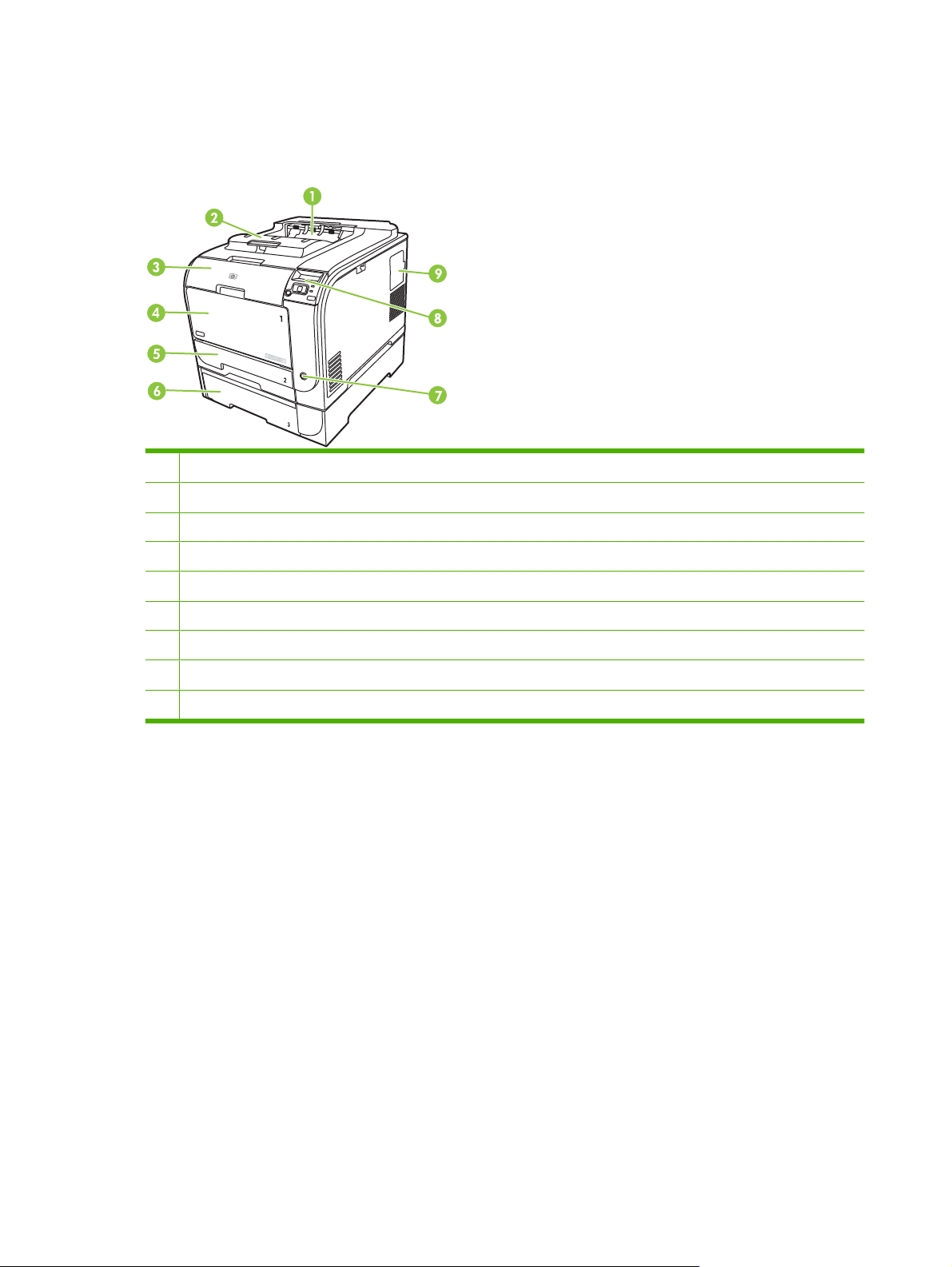
Walkaround
Front and side view
1 Output bin (holds 150 sheets of standard paper)
2 Legal-output extension
3 Front door (provides access to the print cartridges)
4 Tray 1 (multipurpose tray)
5 Tray 2 (holds 250 sheets of standard paper and provides jam access)
6 Optional Tray 3 (holds 250 sheets of standard paper)
7 Power switch
8 Control panel
9 DIMM door (for adding more memory)
4 Chapter 1 Product basics ENWW
Page 25

Back view
1 Hi-Speed USB 2.0 port and network port. (Network port present on HP Color LaserJet CP2025n, HP Color LaserJet
CP2025dn, and HP Color LaserJet CP2025x models only.)
2 Power connection
3 Rear door (for jam access)
Model and serial numbers
The model number and serial number appear on an identification label located inside the front door.
The label contains information about the country/region of origin and the revision level, manufacturing
date, production code, and production number of the product. The label also contains power rating and
regulatory information.
Product No
C
N
HEWLETT
C
B
N
1131
R
B
2
R
BOISE, IDAHO
1
2
Ser
2
1
USA
3
2
1 CHINDEN
4
CNBR21
3
7
.
ial No.
4
CNB
Q3948M
7
-PACKARD
Product of J
Produi
R21
C
N
2347
B
2347
t du
BL
B
83714
1234
apan
J
VD.
22
apon
50/60 Hz, 2.5A
0- 240V ~AC
56
Manuf
Jan
uar
actured
y 3, 2007
(2,5A)
N
u
R
m
e
g
e
é
u
ro
T
la
h
R
re
is
to
u
é
c
d
o
le
g
ry
in
n
e
le
s
M
d
v
te
in
. O
m
ic
i
tio
rf
m
te
o
e
e
p
e
a
rf
c
d
n
n
e
re
y
e
s
e
ta
r
o
T
c
re
:
a
n
l N
m
(1
h
r
ire
tio
c
a
a
n
is
p
e
u
C
d
c
u
)
, a
n
p
li
d
s
ia
e
m
T
F
e
is
e
ro
re
s
u
h
R
tio
n
u
b
w
s
is
m
d
d
c
e
n
c
n
(2
u
u
d
ith
e
h
r B
d
p
c
o
b
iv
a
e
e
t c
)
je
d
e
P
p
s
v
e
O
T
e
rf
é
ira
ic
c
te
d
o
a
o
h
le
t to
IS
,
e
n
rt 1
r 1
rm
is
ble
in
m
f
o
B
d
th
,
c
r
a
5
-0
a
o
m
lu
e
s
n
o
y
e
u
v
p
s
c
d
4
n
ic
b
f
e
w
e
f
in
0
o
-c
o
th
e
r
s
5
g
llo
a
ith
t c
m
h
e
-0
ta
in
tio
a
w
F
C
a
u
n
0
p
te
n
in
u
s
d
C
te
.
D
s
t a
a
rf
g
C
e
r J
R
rd
e
two
h
c
re
H
2
.
c
a
n
e
1
r
c
p
m
e
t a
fu
t
h
n
l
a
y
t
S
ITE
:BO
I
>PET<
ENWW Walkaround 5
Page 26

Supported operating systems
The product supports the following operating systems:
Windows 2000
●
Windows XP (32-bit and 64-bit)
●
Windows Server 2003 (32-bit)
●
Windows Vista (32-bit and 64-bit)
●
Windows Vista Starter
●
Mac OS X V10.2.8 and later
●
Linux; Web only (print driver only)
●
UNIX model scripts; Web only (print driver only)
●
6 Chapter 1 Product basics ENWW
Page 27

Supported product software
Software included with the product
There are several options for completing a recommended install. The Easy Install will complete the
installation with default settings. The Advanced Install allows you to select custom settings and select
the components that are installed.
Recommended Installation for Windows
Printer driver
●
HP Update program
●
HP Customer Participation Program
●
Shop for HP Supplies program
●
Express Installation
An Express installation includes the following software:
Printer driver
●
Printer status and alerts
●
NOTE: Use the Microsoft® Add Printer wizard to install the HP Postscript Universal Emulation Print
Drivers.
Macintosh software
HP Product Setup Assistant
●
HP Device Configuration
●
HP Uninstaller
●
Printer driver
The product comes with software (called a printer driver) for Windows that allows the computer to
communicate with the product. Printer drivers provide access to product features, such as printing on
custom-sized paper, resizing documents, and inserting watermarks.
NOTE: The most recent drivers are available at www.hp.com/go/ljcp2020series_software. Depending
on the configuration of Windows-based computers, the installation program for the product software
automatically checks the computer for Internet access to obtain the latest drivers.
ENWW Supported product software 7
Page 28

Other software provided
Software for Windows
HP ToolboxFX
HP ToolboxFX is a software program that you can use for the following tasks:
Checking the product status
●
Checking the supplies status and ordering supplies online
●
Setting up alerts
●
Viewing and changing product settings
●
Viewing product documentation
●
Gaining access to troubleshooting and maintenance tools
●
To use HP ToolboxFX, perform a Full Installation of the product software from the product CD.
Software for Macintosh
The HP installer provides PostScript Printer Description (PPD) files, Printer Dialog Extensions (PDEs),
and the configure device software for use with Macintosh computers.
PostScript Printer Description (PPD) files
The PPD, in combination with the Apple PostScript printer drivers, provides access to product features.
An installation program for the PPD and other software is provided on the product CD.
Configure the product using a Macintosh
For information about configuring the product using a Macintosh and the embedded Web server (EWS),
Embedded Web server on page 40.
see
Status Alerts software
The Status Alerts software provides information about the current status of the product.
The software also provides pop-up alerts when certain events occur, such as an empty tray or a problem
with the product. The alert includes information about solving the problem.
Software for networks
HP Web Jetadmin
HP Web Jetadmin is a browser-based management tool for network-connected printers within your
intranet. It should be installed only on the system administrator’s computer.
To download a current version of HP Web Jetadmin and for the latest list of supported host systems,
go to
www.hp.com/go/webjetadmin.
When installed on a host server, any client can gain access to HP Web Jetadmin by using a supported
Web browser (such as Microsoft® Internet Explorer 6.x or Netscape Navigator 7.x or later) and
navigating to the HP Web Jetadmin host.
8 Chapter 1 Product basics ENWW
Page 29

Embedded Web server
The EWS provides access to information about product and network activities. This information appears
in a Web browser, such as Microsoft Internet Explorer, Netscape Navigator, or Macintosh OS Safari.
The embedded Web server resides on the product. It is not loaded on a network server. No special
software is installed or configured, but you must have a supported Web browser on your computer.
NOTE: Macintosh users can open the EWS by clicking the Utility button when viewing the print queue.
This starts a Web browser, such as Safari, which allows the user to access the EWS. The EWS can
also be accessed directly by typing the network IP address or DNS name of the product into the Web
browser.
HP USB EWS Gateway software, which is automatically installed, also allows a Web browser to access
the product if the product is connected using a USB cable. Click the Utility button when using a USB
connection to access the EWS though the Web browser.
For a complete explanation of the features and functionality of the embedded Web server, see
Embedded Web server on page 40.
Linux
For information, go to
System requirements
Windows requirements
512 MB of RAM
●
350 MB of disk space
●
Macintosh requirements
256 MB of RAM
●
150 MB of disk space
●
www.hp.com/go/linuxprinting.
ENWW Supported product software 9
Page 30

Connectivity
Supported network operating systems
The following operating systems support network printing:
Recommended software installation
Windows 2003 Server (64-bit)
●
Windows XP (32-bit and 64-bit)
●
Windows Vista (32-bit and 64-bit)
●
Mac OS X V10.2.8, V10.3, V10.5
●
Printer sharing disclaimer
HP does not support peer-to-peer networking, as the feature is a function of Microsoft operating systems
and not of the HP printer drivers. Go to Microsoft at
Supported network protocols
The product supports the TCP/IP network protocol. It is the most widely used and accepted networking
protocol. Many networking services use this protocol. This product also supports IPv4 and IPv6. The
following tables list the networking services/protocols that are supported on the product.
Table 1-2 Printing
Service name Description
port9100 (Direct Mode) Printing service
Printer driver only
Linux (Web only)
●
UNIX model scripts (Web only)
●
www.microsoft.com.
Line printer daemon (LPD) Printing service
ws-print Microsoft plug-and-play printing solution
Table 1-3 Network product discovery
Service name Description
SLP (Service Location Protocol) Device Discovery Protocol, used to help find and configure
mDNS (multicast Domain Name Service - also known as
“Rendezvous” or “Bonjour”)
ws-discover Used by Microsoft-based software programs
Table 1-4 Messaging and management
Service name Description
HTTP (hypertext transfer protocol) Allows Web browsers to communicate with embedded Web
network devices. Used primarily by Microsoft-based software
programs.
Device Discovery Protocol, used to help find and configure
network devices. Used primarily by Apple Macintosh-based
software programs.
server.
10 Chapter 1 Product basics ENWW
Page 31

Table 1-4 Messaging and management (continued)
Service name Description
EWS (embedded Web server) Allows a user to manage the product through a Web browser.
SNMP (simple network management protocol) Used by network programs for product management. SNMP
V1 and standard MIB-II (Management Information Base)
objects are supported.
Table 1-5 IP addressing
Service name Description
DHCP (dynamic host configuration protocol), IPv4, and IPv6 For Automatic IP address assignment. DHCP server provides
BOOTP (bootstrap protocol) For Automatic IP address assignment. BOOTP server
Auto IP For Automatic IP address assignment. If neither a DHCP
the product with an IP address. Generally requires no user
intervention for product to obtain IP address from a DHCP
server.
provides the product with an IP address. Requires an
administrator to type the product MAC hardware address on
the BOOTP server in order for the product to obtain an IP
address from that server.
server nor a BOOTP server is present, this service allows the
product to generate a unique IP address.
ENWW Connectivity 11
Page 32

12 Chapter 1 Product basics ENWW
Page 33

2 Control panel
Control-panel walkaround
●
Control-panel menus
●
ENWW 13
Page 34

Control-panel walkaround
The product has the following items on the control panel.
!
1 Control-panel display: The display provides information about the product. Use the menus on the display to establish
product settings.
2
Back arrow ( ) button: Use this button for the following actions:
Exit the control-panel menus.
●
Scroll back to a previous menu in a submenu list.
●
Scroll back to a previous menu item in a submenu list (without saving changes to the menu item).
●
3
Left arrow ( ) button: Use this button to navigate through the menus or to decrease a value that appears on the display.
4 OK button: Press the OK button for the following actions:
Open the control-panel menus.
●
Open a submenu displayed on the control-panel display.
●
Select a menu item.
●
Clear some errors.
●
Begin a print job in response to a control-panel prompt (for example, when the message [OK] to print appears on
●
the control-panel display).
5
Right arrow ( ) button: Use this button to navigate through the menus or to increase a value that appears on the display.
6 Cancel Job (X) button: Press this button to cancel a print job whenever the attention light is blinking or to exit the control-
panel menus.
7 Ready light (green): The Ready light is on when the product is ready to print. It blinks when the product is receiving print
data.
8 Attention light (amber): The Attention light blinks when the product requires user attention.
14 Chapter 2 Control panel ENWW
Page 35

Control-panel menus
Use the menus
1. Press OK to open the menus.
2. Press the Left arrow (
3. Press OK to select the option. An asterisk (*) displays next to the active selection.
4. Press the Back arrow (
5. Press X to exit the menu without saving any changes.
The sections that follow describe the options for each of the main menus:
Reports menu on page 16
●
System setup menu on page 17
●
Network config. menu on page 20
●
Service menu on page 19
●
) or Right arrow ( ) button to navigate through the listings.
) button to scroll back through the submenus.
ENWW Control-panel menus 15
Page 36

Reports menu
Use the Reports menu to print reports that provide information about the product.
Menu item Description
Demo page Prints a color page that demonstrates print quality
Menu structure Prints a map of the control-panel-menu layout
Config report Prints a list of all the product settings-Including network information when the product
Supplies status Prints the status for each print cartridge, including the following information:
Network report Prints a list of all product network settings
is connected to a network.
Approximate pages remaining
●
Approximate percentage of cartridge life remaining for each color
●
Part number
●
Number of pages printed
●
Usage page Prints a page that lists PCL pages, PCL 6 pages, HP Postscript Emulation Universal
PCL font list Prints a list of all the PCL fonts that are installed.
PS font list Prints a list of all the PostScript (PS) fonts that are installed
PCL6 font list Prints a list of all the PCL6 fonts that are installed
Color usage log Prints a report that shows the user name, program name, and color usage
Service page Prints the service report
Diagnostics page Prints the calibration and color diagnostics pages
Print Driver pages, pages that were jammed or mispicked in the product,
monochrome (black and white) or color pages, and reports the page count
information on a job-by-job basis
16 Chapter 2 Control panel ENWW
Page 37

System setup menu
Use this menu to establish basic product settings. The System setup menu has several submenus that
are described in the following table.
Menu item Sub-menu item Sub-menu item Description
Language Select the language for the control-panel
Paper setup Def. paper size Letter
A4
Legal
Def. paper type A list of available media
types.
Tray 1 Paper size
Paper type
Tray 2 Paper size
Paper type
Tray 3 Paper size
Paper type
Paper out action Wait forever
Override
Cancel
display messages and the product
reports.
Select the size for printing internal
reports or any print job that does not
specify a size.
Select the media type for printing internal
reports or any print job that does not
specify a type.
Select the default size and type for Tray 1
from the list of available sizes and types.
Select the default size and type for Tray 2
from the list of available sizes and types.
If optional Tray 3 is installed, select the
default size and type for Tray 3 from the
list of available sizes and types.
Select how the product should react
when a print job requires a size or type
that is not available or when a specified
tray is empty.
Select Wait forever to make the product
wait until you load the correct media and
press OK. This is the default setting.
Select Override to print on a different
size or type after a specified delay.
Select Cancel to automatically cancel
the print job after a specified delay.
If you select either Override or Cancel,
the control panel prompts you to specify
the number of seconds to delay. Press
) button to increase
) button to decrease the
Print quality Restrict color Enable color
Disable color
the Right arrow (
the time, up to 3600 seconds. Press the
Left arrow (
time.
Select Enable color to allow the job to
print in monochrome (black and white) or
color depending on the job. This is the
default setting.
Select Disable color to make color
printing unavailable. All jobs will print in
monochrome (black and white). Some
internal pages still print in color.
ENWW Control-panel menus 17
Page 38

Menu item Sub-menu item Sub-menu item Description
Calibrate color After power on
Calibrate now
Cartridge low (1-20) The percentage threshold determines
Replace Supplies Override out
Stop at out
Color Supply Out Stop Printing (default)
Continue Black
After power on: Select how soon the
product will calibrate after you turn it on.
The default setting is 15 minutes.
Calibrate now: Makes the product
perform a calibration immediately. If a job
is processing, the product calibrates after
the job is complete. If an error message
is displayed, you must clear the error
first.
when the product begins reporting low
toner. The message is either reported on
the control-panel display or using the
toner LED, if it exists.
Override out: If the product determines
that a print cartridge has reached the end
of life, select this setting to continue
printing until there is a decrease in print
quality.
Stop at out: If the product determines
that a print cartridge is empty, the
cartridge must be replaced before
printing can continue. This is the default
setting.
Stop Printing: If the product determines
that a color cartridges is empty, it stops
printing. This is the default setting.
Adjust Alignment Print Test Page
Adjust Tray <X>
Display contrast Lightest
Lighter
Medium
Darker
Darkest
Select the level of contrast for the
Continue Black: If the product
determines that a color cartridges is
empty, continue printing using black
only.
Print Test Page: Print a test page that
tests printer alignment.
Adjust Tray <X>: Adjust the alignment
of the specified tray.
display. The default setting is Medium.
18 Chapter 2 Control panel ENWW
Page 39

Service menu
Use this menu to restore default settings, clean the product, and start special modes that affect print
output.
Menu item Sub-menu item Description
Cleaning mode Use this option to clean the product if you see toner specks or
PowerSave Sets how long the product remains idle before it enters
USB speed High
Full
Less paper curl Off
On
Archive print Off
On
other marks on the printed output. The cleaning process
removes dust and excess toner from the paper path.
When you select this item, the product prompts you to load
plain paper in Tray 1 and then press OK to start the cleaning
process. Wait until the process is complete. Discard the page
that prints.
PowerSave mode. The product automatically exits
PowerSave mode when you send a print job or press a control-
panel button.
The default setting is 1 minute.
Sets the USB speed to High or Full. For the product to actually
operate at high speed, it must have high speed enabled and
be connected to an EHCI host controller that is also operating
at high speed. This menu item also does not reflect the current
operating speed of the product.
The default setting is High.
If printed pages are consistently curled, use this option to set
the product to a mode that reduces curl.
The default setting is Off.
If you are printing pages that will be stored for a long time, use
this option to set the product to a mode that reduces toner
smearing and dusting.
The default setting is Off.
Restore defaults Press OK to restore the factory default settings to the default
values.
ENWW Control-panel menus 19
Page 40

Network config. menu
Use this menu to establish network configuration settings.
Menu item Sub-menu item Description
TCP IP config Automatic
Manual
Auto crossover On
Off
Network services IPv4
IPv6
DHCPv6
Show IP address No
Yes
Select Automatic to automatically configure all the
TCP/IP settings.
Select Manual to manually configure the IP address,
subnet mask, and default gateway.
The default setting is Automatic.
This item is used when you are connecting the
product directly to a personal computer using an
Ethernet cable (you might have to set this to On or
Off depending on the computer being used).
The default setting is On.
This item is used by the system administrator to limit
the network services available on this product.
On
Off
The default setting for all items is On.
No: The product IP address does not appear on the
control-panel display.
Yes: The product IP address appears on the controlpanel display, alternating between supplies
information and the IP address of the device. The IP
address does not display if an error condition exits.
The default setting is No.
Link speed Automatic (default)
10T Full
10T Half
100TX Full
100TX Half
Restore defaults Press OK to restore the network configuration
Sets the link speed manually if needed.
After setting the link speed, the product automatically
restarts.
settings to the default values.
20 Chapter 2 Control panel ENWW
Page 41

3 Paper and print media
ENWW 21
Page 42

Understand paper and print media use
This product supports a variety of paper and other print media in accordance with the guidelines in this
user guide. Paper or print media that does not meet these guidelines might cause the following problems:
Poor print quality
●
Increased jams
●
Premature wear on the product, requiring repair
●
For best results, use only HP-brand paper and print media designed for laser printers or multiuse. Do
not use paper or print media made for inkjet printers. Hewlett-Packard Company cannot recommend
the use of other brands of media because HP cannot control their quality.
It is possible for paper to meet all of the guidelines in this user guide and still not produce satisfactory
results. This might be the result of improper handling, unacceptable temperature and/or humidity levels,
or other variables over which Hewlett-Packard has no control.
CAUTION: Using paper or print media that does not meet Hewlett-Packard's specifications might
cause problems for the product, requiring repair. This repair is not covered by the Hewlett-Packard
warranty or service agreements.
22 Chapter 3 Paper and print media ENWW
Page 43

Supported paper and print media sizes
This product supports several paper sizes, and it adapts to various media.
NOTE: To obtain the best print results, select the correct paper size and type in your print driver before
printing.
Table 3-1 Supported paper and print media sizes
Size Dimensions Tray 1 Tray 2 or optional Tray
Letter 216 x 279 mm (8.5 x 11 inches)
Legal 216 x 356 mm (8.5 x 14 inches)
A4 210 x 297 mm (8.27 x 11.69 inches)
Executive 184 x 267 mm (7.24 x 10.51 inches)
A3 297 x 420 mm (11.69 x 16.54 inches)
A5 148 x 210 mm (5.83 x 8.27 inches)
A6 105 x 148 mm (4.13 x 5.83 inches)
B4 (JIS) 257 x 364 mm (10.12 x 14.33 inches)
3
B5 (JIS) 182 x 257 mm (7.17 x 10.12 inches)
B5 (ISO) 176 x 250 mm (6.93 x 9.84 inches)
B6 (ISO) 125 x 176 mm (4.92 x 6.93 inches)
16k 184 x 260 mm (7.24 x 10.23 inches)
195 x 270 mm (7.68 x 10.62 inches)
197 x 273 mm (7.75 x 10.75 inches)
8.5 x 13 216 x 330 mm (8.5 x 13 inches)
4 x 6 107 x 152 mm (4 x 6 inches)
5 x 8 127 x 203 mm (5 x 8 inches)
10 x 15 cm 100 x 150 mm (3.9 x 5.9 inches)
Custom (76 - 216) x (127 - 356) mm ((3 - 8.5) x (5 - 14) inches)
Custom (102 - 216) x (153 - 356) mm ((4 - 8.5) x (6 - 14)
inches)
Table 3-2 Supported envelopes and postcards
Size Dimensions Tray 1 Tray 2
Envelope #10 105 x 241 mm (4.13 x 9.49 inches)
ENWW Supported paper and print media sizes 23
Page 44

Table 3-2 Supported envelopes and postcards (continued)
Size Dimensions Tray 1 Tray 2
Envelope DL 110 x 220 mm (4.33 x 8.66 inches)
Envelope C5 162 x 229 mm (6.93 x 9.84 inches)
Envelope B5 176 x 250 mm (6.7 x 9.8 inches)
Envelope
Monarch
Postcard 100 x 148 mm (3.94 x 5.83 inches)
Double postcard 148 x 200 mm (5.83 x 7.87 inches)
98 x 191 mm (3.9 x 7.5 inches)
24 Chapter 3 Paper and print media ENWW
Page 45

Supported paper types and tray capacity
Table 3-3 Tray 1
Media type Weight Capacity
1
Paper orientation
Every day:
Plain
●
Light
●
Bond
●
Recycled
●
Presentation:
Matte paper, midweight to
●
heavy
Glossy paper, midweight to
●
heavy
Brochure:
Matte paper, midweight to
●
heavy
Glossy paper, midweight to
●
heavy
Photo and cover:
Matte cover paper
●
Glossy cover paper
●
60 to 90 g/m2 (16 to 24 lb)
Up to 176 g/m2 (47 lb)
Up to 176 g/m2 (47 lb)
Up to 176 g/m2 (47 lb)
2
2
2
Up to 50 sheets Side to be printed, place face-up,
with the top edge at the back of
the tray
Up to 5 mm (0.2 inch) stack
height
Side to be printed, place face-up,
with the top edge at the back of
the tray
Up to 5 mm (0.2 inch) stack
height
Side to be printed, place face-up,
with the top edge at the back of
the tray
Up to 5 mm (0.2 inch) stack
height
Side to be printed, place face-up,
with the top edge at the back of
the tray
Matte photo paper
●
Glossy photo paper
●
Card stock
●
Other:
Color laser transparency
●
Labels
●
Letterhead envelope
●
Heavy envelope
●
Preprinted
●
Prepunched
●
Colored
●
Rough
●
Tough
●
1
Capacity can vary depending on media weight and thickness, and environmental conditions.
2
The device supports up to 220 g/m2 (59 lb) for glossy and glossy photo paper.
Up to 50 sheets or 10 envelopes Side to be printed, place face-up,
with the top edge at the back of
the tray or the stamp-end at the
back of the tray
ENWW Supported paper types and tray capacity 25
Page 46

Table 3-4 Tray 2 and Tray 3
Media type Weight Capacity
1
Paper orientation
Every day:
Plain
●
Light
●
Bond
●
Recycled
●
Presentation:
Matte paper, midweight to
●
heavy
Glossy paper, midweight to
●
heavy
Brochure:
Matte paper, midweight to
●
heavy
Glossy paper, midweight to
●
heavy
Photo and cover:
Matte cover paper
●
Glossy cover paper
●
60 to 90 g/m2 (16 to 24 lb)
Up to 176 g/m2 (47 lb)
Up to 176 g/m2 (47 lb)
Up to 176 g/m2 (47 lb)
2
2
2
Up to 250 sheets Side to be printed, place face-up,
with the top edge at the back of
the tray
Up to 12.5 mm (0.5 inch) stack
height
Side to be printed, place face-up,
with the top edge at the back of
the tray
Up to 12.5 mm (0.5 inch) stack
height
Side to be printed, place face-up,
with the top edge at the back of
the tray
Up to 12.5 mm (0.5 inch) stack
height
Side to be printed, place face-up,
with the top edge at the back of
the tray
Matte photo paper
●
Glossy photo paper
●
Card stock
●
Other:
Color laser transparency
●
Labels
●
Letterhead envelope
●
Heavy envelope
●
Preprinted
●
Prepunched
●
Colored
●
Rough
●
Tough
●
1
Capacity can vary depending on media weight and thickness, and environmental conditions.
2
The device supports up to 220 g/m2 (59 lb) for glossy and glossy photo paper.
Up to 50 sheets or 10 envelopes Side to be printed, place face-up,
with the top edge at the back of
the tray or the stamp-end at the
back of the tray
26 Chapter 3 Paper and print media ENWW
Page 47

Special paper or print media guidelines
This product supports printing on special media. Use the following guidelines to obtain satisfactory
results. When using special paper or print media, be sure to set the type and size in your print driver to
obtain the best print results.
CAUTION: HP LaserJet printers use fusers to bond dry toner particles to the paper in very precise
dots. HP laser paper is designed to withstand this extreme heat. Using inkjet paper not designed for this
technology could damage your printer.
Media type Do Do not
Envelopes
Labels
Transparencies
Letterhead or preprinted forms
Heavy paper
Store envelopes flat.
●
Use envelopes where the seam
●
extends all the way to the corner of
the envelope.
Use peel-off adhesive strips that
●
are approved for use in laser
printers.
Use only labels that have no
●
exposed backing between them.
Use Labels that lie flat.
●
Use only full sheets of labels.
●
Use only transparencies that are
●
approved for use in laser printers.
Place transparencies on a flat
●
surface after removing them from
the product.
Use only letterhead or forms
●
approved for use in laser printers.
Use only heavy paper that is
●
approved for use in laser printers
and meets the weight specifications
for this product.
Do not use envelopes that are
●
wrinkled, nicked, stuck together, or
otherwise damaged.
Do not use envelopes that have
●
clasps, snaps, windows, or coated
linings.
Do not use self-stick adhesives or
●
other synthetic materials.
Do not use labels that have wrinkles
●
or bubbles, or are damaged.
Do not print partial sheets of labels.
●
Do not use transparent print media
●
not approved for laser printers.
Do not use raised or metallic
●
letterhead.
Do not use paper that is heavier
●
than the recommended media
specification for this product unless
it is HP paper that has been
approved for use in this product.
Glossy or coated paper
Use only glossy or coated paper
●
that is approved for use in laser
printers.
Do not use glossy or coated paper
●
designed for use in inkjet products.
ENWW Special paper or print media guidelines 27
Page 48

Load paper and print media
Load Tray 1
1. Open Tray 1.
2. If loading long sheets of media, pull out the extension tray.
3. If necessary, flip out the extension.
28 Chapter 3 Paper and print media ENWW
Page 49

4. Extend the paper guides fully (callout 1) and then load the media stack into Tray 1 (callout 2). Adjust
the paper guides to the size of the paper.
NOTE: Place the media into Tray 1 with the side to be printed on face-up and the top toward the
product.
Load Tray 2 or 3
1. Pull the tray out of the product.
2. Slide open the paper length and width guides.
To load Legal-size paper, extend the tray by pressing and holding the extension tab (callout1)
●
while pulling the front of the tray toward you.
1
NOTE: When it is loaded with Legal-size paper, the tray extends from the front of the product
about 64 mm (2.5 inches).
ENWW Load paper and print media 29
Page 50

3. Place the paper in the tray and ensure that it is flat at all four corners. Slide the paper length and
width guides so that they are against the stack of paper.
4. Push down on the paper to ensure that the paper stack is below the paper limit tabs on the side of
the tray.
5. Slide the tray into the product.
30 Chapter 3 Paper and print media ENWW
Page 51

4 Manage and maintain
Information pages
●
HP ToolboxFX
●
Embedded Web server
●
HP Web Jetadmin
●
Manage supplies
●
Replace print cartridges
●
Memory and font DIMMs
●
Clean the product
●
Firmware updates
●
ENWW 31
Page 52

Information pages
Use the control panel to print information pages that give details about the product and its current
settings.
1. Press OK to open the menus.
2. Press the Left arrow (
3. Press the Left arrow (
OK to print a report.
4. Press X to exit the menus.
The following information pages are available:
Demo page
●
Menu structure
●
Configuration page
●
Supplies status page
●
Network configuration page
●
Usage report
●
PCL font list
●
PS font list
●
PCL6 font list
●
Color usage report
●
) or Right arrow ( ) button to navigate to Reports, and then press OK.
) or Right arrow ( ) button to navigate through the reports, and then press
Service report
●
Diagnostics report
●
32 Chapter 4 Manage and maintain ENWW
Page 53

HP ToolboxFX
Open HP ToolboxFX
Open HP ToolboxFX in one of these ways:
Status
●
In the Windows notification area, double-click the HP ToolboxFX icon (
On the Windows Start menu, click Programs (or All Programs in Windows XP and Vista), click
●
HP, click HP Color LaserJet CP2020 Series, and then click HP ToolboxFX.
HP ToolboxFX contains the following folders:
Status on page 33
●
Alerts on page 34
●
Product information on page 34
●
Help on page 35
●
Device Settings on page 36
●
Network Settings on page 39
●
The Status folder contains links to the following main pages:
Device status. This page indicates product conditions such as a jam or an empty tray. After you
●
correct a problem, click Refresh status to update the product status.
Supplies status. View details such as the approximate percent of toner remaining in the print
●
cartridge and the number of pages that have been printed with the current print cartridge. This page
also has links for ordering supplies and for finding recycling information.
).
Device configuration. View a detailed description of the current product configuration, including
●
the amount of memory installed and whether optional trays are installed.
Network summary. View a detailed description of the current network configuration, including the
●
IP address and network status.
Print info pages. Print the Configuration page and other information pages, such as the Supplies
●
status page. See
Color usage job log. View color usage information for recently printed documents.
●
Event log. View a history of product events. The most recent event is listed first.
●
Information pages on page 32.
Event log
The Event log is a table that contains codes corresponding to error messages that have appeared on
the product control-panel display, a brief description of each error, and the number of pages that printed
when each error occurred. For more information about error messages, see
ENWW HP ToolboxFX 33
Event log on page 202.
Page 54

Alerts
The Alerts folder contains links to the following main pages:
Set up Status Alerts. Set up the product to send you pop-up alerts for certain events, such as low
●
levels of cartridge life.
Set up E-mail Alerts. Set up the product to send you e-mail alerts for certain events, such as low
●
levels of cartridge life.
Set up Status Alerts
Use this to set up the product so that it sends alerts to your computer when the following occur: jams,
low levels of toner in HP print cartridges, a non-HP print cartridge in use, empty input trays, and specific
error messages.
Select to receive a pop-up, a Windows notification area icon, a desktop alert, or any combination of
these. The pop-up and desktop alerts appear only when the product is printing from the computer on
which you set up the alerts. Desktop alerts are only visible momentarily and disappear automatically.
Change the Cartridge low threshold setting, which sets the toner level that causes a low toner alert,
on the System setup page.
NOTE: You must click Apply before your changes take effect.
Set up E-mail Alerts
Use this to configure up to two e-mail addresses to receive alerts when certain events occur. You can
specify different events for each e-mail address. Use the information for the e-mail server that will send
out the e-mail alert messages for the product.
NOTE: You can only configure e-mail alerts to be sent from a server that does not require user
authentication. If your e-mail server requires you to log in with a user name and password, you cannot
enable e-mail alerts.
NOTE: You must click Apply before your changes take effect.
Product information
The Product information folder contains links to the following page:
Demonstration Pages. Print pages that show the color print quality potential and overall print
●
characteristics of the product.
Set password
Use HP ToolboxFX or the embedded Web server to set a system password.
1. In the embedded Web server, click the Settings tab.
In HP ToolboxFX, click the Device Settings tab.
NOTE: If a password has already been set, you are prompted for it. Type the password, and then
click Apply.
2. Click Password.
34 Chapter 4 Manage and maintain ENWW
Page 55

Help
3. In the Password box, type the password that you want to set, and then in the Confirm
password box, type the same password again to confirm your choice.
4. Click Apply to save the password.
The Help folder contains links to the following main pages:
Troubleshooting. View troubleshooting help topics, print troubleshooting pages, clean the
●
product, and open Microsoft Office Basic Colors.
Paper and Print Media. Print information about how to obtain optimal results from your product
●
using various types of paper and print media.
Color Printing Tools. Open Microsoft Office Basic Colors or the full palette of colors with
●
associated RGB values. Use the HP Basic Color Match to adjust spot colors in your printed output.
Animated Demonstrations. View animations that show how to perform common tasks on your
●
device, such as how to get the best print quality, how to remove paper jams, and how to replace
a print cartridge.
User Guide. View information about the product usage, warranty, specifications, and support. The
●
User Guide is available in both HTML and PDF format.
ENWW HP ToolboxFX 35
Page 56

Device Settings
The Device Settings folder contains links to the following main pages:
Device Information. View information such as the product description and a contact person.
●
Paper Handling. Configure trays or change the product paper-handling settings, such as default
●
paper size and default paper type.
Printing. Change the default product print settings, such as number of copies and paper
●
orientation.
PCL5c. Change the PCL settings.
●
PostScript. Change the PS settings.
●
Print Quality. Change the print-quality settings.
●
Print Density. Change the print-density settings, such as contrast, highlights, midtones, and
●
shadows.
Paper Types. Change the mode settings for each media type, such as letterhead, prepunched, or
●
glossy paper.
System Setup. Change the system settings, such as jam recovery and auto-continue. Change the
●
Cartridge low threshold setting, which sets the toner level that causes a low toner alert.
Save/Restore Settings. Save the current settings for the product to a file on your computer. Use
●
this file to load the same settings onto another product or to restore these settings to this product
at a later time.
Password. Set a password to protect the device settings. After a password is set, users are
●
prompted to type the password before being allowed to change device settings. This password is
the same as the embedded Web server password.
Device Information
The Device Information page stores data about your product for future reference. The information that
you type in the fields on this page appears on the Configuration page. You can type any character in
each of these fields.
NOTE: You must click Apply before your changes take effect.
36 Chapter 4 Manage and maintain ENWW
Page 57

Paper Handling
Use these options to configure your default settings. These are the same options that are available on
the control-panel menus on the control panel. For more information, see
on page 15.
The following options are available for handling print jobs when the product is out of media:
Select Wait for paper to be loaded.
●
Select Cancel from the Paper out action drop-down list to cancel the print job.
●
Select Override from the Paper out time drop-down list to send the print job to another paper tray.
●
The Paper out time field specifies how long the product waits before acting on your selections. You
can specify from 0 to 3600 seconds.
NOTE: You must click Apply before your changes take effect.
Printing
Use these options to configure the settings for all print functions. These are the same options that are
available on the control panel. For more information, see
NOTE: You must click Apply before your changes take effect.
Control-panel menus
Control-panel menus on page 15.
PCL5c
Use these options to configure the settings when you are using the PCL print personality.
NOTE: You must click Apply before your changes take effect.
PostScript
Use this option when you are using the PostScript print personality. When the Print PostScript error
option is turned on, the PostScript error page automatically prints when PostScript errors occur.
NOTE: You must click Apply before your changes take effect.
ENWW HP ToolboxFX 37
Page 58

Print Quality
Use these options to improve the appearance of your print jobs. These are the same options that are
available on the control panel menus. For more information, see
Color Calibration
Power On Calibration. Specify whether the product calibrates when you turn it on.
●
Calibration Timing. Specify how frequently the product will calibrate.
●
Calibrate Now. Set the product to calibrate immediately.
●
NOTE: You must click Apply before your changes take effect.
Print Density
Use these settings to make fine adjustments in the amount of each color of toner that is used for your
printed documents.
Contrasts. Contrast is the range of difference between light (highlight) and dark (shadow) colors.
●
To increase the overall range between light and dark colors, increase the Contrasts setting.
Highlights. Highlights are colors that are nearly white. To darken highlight colors, increase the
●
Highlights setting. This adjustment does not affect midtone or shadow colors.
Midtones. Midtones are colors that are halfway between white and solid density. To darken
●
midtone colors, increase the Midtones setting. This adjustment does not affect highlight or shadow
colors.
Control-panel menus on page 15.
Shadows. Shadows are colors that are nearly solid density. To darken shadow colors, increase
●
the Shadows setting. This adjustment does not affect highlight or midtone colors.
Paper Types
Use these options to configure print modes that correspond to the various media types. To reset all
modes to factory default settings, select Restore modes.
NOTE: You must click Apply before your changes take effect.
System Setup
Use these system settings to configure miscellaneous print settings. These settings are not available
on the control panel.
NOTE: You must click Apply before your changes take effect.
Save/Restore Settings
Save the current settings for the product to a file on your computer. Use this file to load the same settings
onto another product or to restore these settings to this product at a later time.
Password
Set a password to protect the device settings. After a password is set, users are prompted to type the
password before they can access any of the HP ToolboxFX pages that read or write data from the device.
This password is the same as the embedded Web server password.
38 Chapter 4 Manage and maintain ENWW
Page 59

Service
During the printing process, paper, toner, and dust particles can accumulate inside the product. Over
time, this buildup can cause print-quality problems such as toner specks or smearing. HP ToolboxFX
provides an effective method for cleaning the paper path.
Network Settings
The system administrator can use this tab to control the network-related settings for the product when
it is connected to an IP-based network.
Shop for Supplies
This button, at the top of each page, links to a Web site where you can order replacement supplies. You
must have Internet access to use this feature.
Other Links
This section contains links that connect you to the Internet. You must have Internet access to use any
of these links. If you use a dial-up connection and did not connect when you first opened HP ToolboxFX,
you must connect before you can visit these Web sites. Connecting might require that you close
HP ToolboxFX and reopen it.
HP Instant Support. Connects to the HP Instant Support Web site.
●
Support and Troubleshooting. Connects to the support site for the product where you can search
●
for help with a specific problem.
Product Registration. Connects to the HP product registration Web site.
●
ENWW HP ToolboxFX 39
Page 60

Embedded Web server
When the product is connected to the network, the embedded Web server is automatically available.
The embedded Web server can be accessed through a standard Web browser.
NOTE: When the product is directly connected to a computer, use the HP ToolboxFX to view the
product status.
Use the embedded Web server to view product and network status and to manage printing functions
from your computer instead of from the product control panel.
View product control status information.
●
Set the type of paper loaded in each tray.
●
Determine the remaining life of all supplies and order new ones.
●
View and change tray configurations.
●
View and change the product settings.
●
View and change network configuration.
●
View support content that is specific to the current state of the product.
●
Restrict access to color-printing features.
●
To use the embedded Web server, you must have Microsoft Internet Explorer 6 or later, Netscape
Navigator 7 or later, Safari 1.2 or later, Konqueror 3.2 or later, Firefox 1.0 or later, Mozilla 1.6 or later,
or Opera 7 or later. The embedded Web server works when the product is connected to an IP-based
network. The embedded Web server does not support IPX-based or AppleTalk printer connections. You
do not need Internet access to open and use the embedded Web server.
View the HP embedded Web server
1. In a supported Web browser on your computer, type the IP address for the product in the address/
URL field. To find the IP address, print a configuration page (see
NOTE: After you open the URL, you can bookmark it so that you can return to it quickly in the
future.
2. The embedded Web server has three tabs that contain settings and information about the product:
the Status tab, the Settings tab, and the Networking tab. Click the tab that you want to view.
See the following section for more information about each tab.
Information pages on page 32).
40 Chapter 4 Manage and maintain ENWW
Page 61

Embedded Web server sections
The table below describes the basic screens of the embedded Web server.
Tab or section Description
Status tab
Provides product, status, and
configuration information.
Settings tab
Provides the ability to configure the
product from your computer.
Device Status: Shows the product status and shows the life remaining of
●
HP supplies, with 0% indicating that a supply is empty.
Supplies Status: Shows the approximate life remaining of HP supplies, with 0
●
percent indicating that a supply is empty. This page also provides supplies part
numbers.
Device Configuration: Shows the information found on the product Configuration
●
page.
Network Summary: Shows the information found on the product Network
●
Configuration page.
Print Info Pages: Allows you to print the PCL, PCL6, PS Font Lists, and the supplies
●
status page that the product generates.
Color Usage Job Log: Shows user color print jobs on a job-by-job basis.
●
Event Log: Shows a list of all product events and errors.
●
Support button: Provides a link to the product support page. The Support button
●
can be password-protected; see
Shop for Supplies button: Provides a link to a page where you can order supplies
●
for the product. The Shop for Supplies button can be password-protected; see
password on page 34
Device Information: Allows you to name the product and assign an asset number
●
to it. Also type the name for the primary contact who will receive information about
the product.
Paper Handling: Allows you to change the paper-handling defaults for the product.
●
Set password on page 34
Set
Printing: Allows you to change the printing defaults for the product.
●
PCL 5c: Allows you to change the PCL 5c defaults for the product.
●
PostScript: Allows you to change the PostScript defaults for the product.
●
Print Quality: Allows you to change the print quality defaults for the product,
●
including calibration settings.
Print Density: Allows you to change the contrasts, highlights, midtones, and
●
shadows values for each supply.
Paper Types: Allows you to configure print modes that correspond to the media
●
types that the product accepts.
System Setup: Allows you to change the system defaults for the product.
●
Service: Allows you to start the cleaning procedure on the product.
●
Support button: Provides a link to the product support page. The Support button
●
can be password-protected.
Shop for Supplies button: Provides a link to a page where you can order supplies
●
for the product. The Shop for Supplies button can be password-protected.
ENWW Embedded Web server 41
Page 62

Tab or section Description
NOTE: The Settings tab can be password-protected; see Set password on page 34. If
this product is on a network, always consult with the printer administrator before changing
settings on this tab.
Networking tab
Provides the ability to change
network settings from your
computer.
System administrators can use this tab to control network-related settings for the product
when it is connected to an IP-based network.
NOTE: The Networking tab can be password-protected; see
on page 34.
Set password
42 Chapter 4 Manage and maintain ENWW
Page 63

HP Web Jetadmin
HP Web Jetadmin is a browser-based management tool for HP Jetdirect-connected printers within your
intranet, and it should be installed only on the network administrator’s computer.
To download a current version of HP Web Jetadmin and for the latest list of supported host systems,
visit
www.hp.com/go/webjetadmin.
When installed on a host server, a Windows client can gain access to HP Web Jetadmin by using a
supported Web browser (such as Microsoft® Internet Explorer 4.x or Netscape Navigator 4.x or later)
by navigating to the HP Web Jetadmin host.
ENWW HP Web Jetadmin 43
Page 64

Manage supplies
Supplies life
The print cartridge use HP ColorSphere toner. For information about the number of pages the cartridges
can print, see
Print-cartridge storage
Do not remove the print cartridge from its package until you are ready to use it.
CAUTION: To prevent damage to the print cartridge, do not expose it to light for more than a few
minutes.
HP policy on non-HP print cartridges
Hewlett-Packard Company cannot recommend the use of non-HP print cartridges, either new or
remanufactured.
NOTE: Any damage caused by a non-HP print cartridge is not covered under the HP warranty and
service agreements.
To install a new HP print cartridge, see Replace print cartridges on page 46. To recycle the used
cartridge, follow the instructions included with the new cartridge.
www.hp.com/go/pageyield. Actual yield depends on specific use.
HP fraud hotline and Web site
Call the HP fraud hotline (1-877-219-3183, toll-free in North America) or go to www.hp.com/go/
anticounterfeit when you install an HP print cartridge and the control-panel message says the cartridge
is non-HP. HP will help determine if the cartridge is genuine and take steps to resolve the problem.
Your print cartridge might not be a genuine HP print cartridge if you notice the following:
You are experiencing a high number of problems with the print cartridge.
●
The cartridge does not look like it usually does (for example, the orange pull tab is missing, or the
●
packaging differs from HP packaging).
44 Chapter 4 Manage and maintain ENWW
Page 65

Print when cartridge is out
An Order Supplies message appears when a print cartridge is nearing the end of its life. A Replace
Supplies message appears when the print cartridge is depleted. To ensure optimal print quality,
HP recommends replacing a print cartridge when the Replace Supplies message displays. Print-quality
problems can occur when using a cartridge that is depleted, resulting in waste of print media and toner
from other cartridges. Replacing a print cartridge when the Replace Supplies message displays can
prevent this waste.
The Auto continue feature in HP ToolboxFX allows the product to continue using a print cartridge that
has reached the recommended replacement point.
WARNING! Using the Auto continue feature can result in unsatisfactory print quality.
WARNING! All print defects or supply failures incurred when an HP supply is used in cartridge-out-
override mode will not be considered to be defects in materials or workmanship in the supply under the
HP Print Cartridge Warranty Statement. For warranty information, see
statement on page 268.
You can enable or disable the Auto continue feature at any time, and you do not have to re-enable it
when you install a new print cartridge. When the Auto continue feature is turned on, the product
automatically continues printing when a print cartridge reaches the recommended replacement level. A
Replace Supplies Override In Use message displays while a print cartridge is being used in override
mode. When you replace the print cartridge with a new supply, the product deactivates the override
mode until another print cartridge reaches the recommended replacement level.
Print cartridge limited warranty
Enable or disable the Cartridge-out-override feature
1. Open HP ToolboxFX.
2. Click the Device Settings folder, and then click System Setup.
3. Next to Auto continue, select On to activate the feature. Select Off to make it unavailable.
Enable or disable the Cartridge-out-override feature from the control panel
1. On the control-panel menu, press OK.
2. Use the Left arrow (
OK.
3. Use the Left arrow (
4. Use the Left arrow (
OK.
5. To activate the feature, select Override out. Select Stop at out to make it unavailable.
) or the Right arrow ( ) button to select System setup, and then press
) or the Right arrow ( ) button to select Print quality, and then press OK.
) or the Right arrow ( ) button to select Replace Supplies, and then press
ENWW Manage supplies 45
Page 66

Replace print cartridges
1. Open the front door.
2. Pull out the print-cartridge drawer.
3. Grasp the handle on the old print cartridge and then pull the cartridge straight up to remove it.
4. Remove the new print cartridge from the packaging.
46 Chapter 4 Manage and maintain ENWW
Page 67

5. Remove the orange, plastic shield from the bottom of the new print cartridge.
CAUTION: Do not touch the imaging drum on the bottom of the print cartridge. Fingerprints on
the imaging drum can cause print-quality problems.
6. Insert the new print cartridge into the product.
ENWW Replace print cartridges 47
Page 68

7. Pull the tab on the left side of the print cartridge straight up to completely remove the sealing tape.
Discard the sealing tape.
8. Close the print-cartridge drawer.
48 Chapter 4 Manage and maintain ENWW
Page 69

9. Close the front door.
10. Place the old print cartridge in the box for the new print cartridge. Follow the recycling instructions
that are included in the box.
ENWW Replace print cartridges 49
Page 70

Memory and font DIMMs
Product memory
The product has one dual inline memory module (DIMM) slot. Use the DIMM slot to upgrade the product
with the following items:
More product memory (DIMMs are available in 64, 128, and 256 MB)
●
Other DIMM-based printer languages and product options
●
Support-language character sets (for example, Chinese characters or Cyrillic alphabet characters).
●
NOTE: To order DIMMs, see Order parts, accessories, and supplies on page 230.
You might want to increase product memory if you often print complex graphics, HP Postscript Universal
Emulation Printer Driver documents, or if you use many downloaded fonts. More memory also enables
multiple collated copies to print at the maximum speed.
Before ordering more memory, see how much memory is installed by printing a Configuration page. See
Information pages on page 32.
CAUTION: Static electricity can damage electronic parts. When installing DIMMs, either wear an
antistatic wrist strap, or frequently touch the surface of the DIMM antistatic package and then touch bare
metal.
Install memory and font DIMMs
1. Turn the product off, and then disconnect all power and interface cables.
2. On the right side of the product, open the DIMM access door.
50 Chapter 4 Manage and maintain ENWW
Page 71

3. Remove the DIMM access door.
4. To replace an installed DIMM, spread the latches apart on each side of the DIMM slot, lift the DIMM
up at an angle, and then pull it out.
5. Remove the new DIMM from the antistatic package, and then find the alignment notch on the
bottom edge of the DIMM.
ENWW Memory and font DIMMs 51
Page 72

6. Holding the DIMM by the edges, align the notch on the DIMM with the bar in the DIMM slot at an
angle.
7. Push down on the DIMM until both latches engage the DIMM. When the installation is correct, the
metal contacts are not visible.
NOTE: If you have difficulty inserting the DIMM, check that the notch on the bottom of the DIMM
is aligned with the bar in the slot. If the DIMM still does not go in, ensure that you are using the
correct DIMM type.
8. Reinsert the DIMM access door.
52 Chapter 4 Manage and maintain ENWW
Page 73

9. Close the DIMM access door.
10. Reconnect the power cable and USB or network cable, and then turn on the product.
11. After installing a memory DIMM, see
Enable memory on page 54.
ENWW Memory and font DIMMs 53
Page 74

Enable memory
If you installed a memory DIMM, set the printer driver to recognize the newly added memory.
Enable memory for Windows
1. On the Start menu, point to Settings, and click Printers or Printers and Faxes.
2. Select this product and select Properties.
3. On the Configure tab, click More.
4. In the Total Memory field, type or select the total amount of memory that is now installed.
5. Click OK.
Check DIMM installation
Turn the product on. Check that the product is in the Ready state after it has gone through the startup
sequence. If an error message displays, do the following:
1. Print a Configuration page. See
2. Check the Installed Personalities and Options section on the Configuration page and compare it
with the Configuration page that you printed before the DIMM installation.
3. The DIMM might not be installed correctly. Repeat the installation procedure.
-or-
The DIMM might be defective. Try a new DIMM.
Clean the product
During the printing process, paper, toner, and dust particles can accumulate inside the product. Over
time, this buildup can cause print-quality problems such as toner specks or smearing. This product has
a cleaning mode that can correct and prevent these problems.
Clean the product using HP ToolboxFX
1. Open HP ToolboxFX. See
2. Click the Device Settings folder, and then click the Service page.
3. In the area for Cleaning Mode, click Start to begin the cleaning process.
The product processes a single page, and then returns to the Ready state when the cleaning
process is complete.
Information pages on page 32.
Open HP ToolboxFX on page 33.
Clean the product using the control panel
1. Press OK to open the menus.
2. Press the Left arrow (
3. Press OK. An asterisk (*) displays next to the active selection.
54 Chapter 4 Manage and maintain ENWW
) or Right arrow ( ) button to highlight Service.
Page 75

4. Press the Left arrow ( ) or Right arrow ( ) button to highlight Cleaning mode .
5. Press OK.
Clean the product using the embedded Web server
1. Open the embedded Web server.
2. Click the Settings tab.
3. Click the Service menu.
4. Click Start.
Firmware updates
To upgrade the product firmware, download the firmware-update file from www.hp.com/go/
ljcp2020series_software, and save the file to your network or personal computer. See the product install
notes for instructions on how to install the firmware-update file on the product.
ENWW Firmware updates 55
Page 76

56 Chapter 4 Manage and maintain ENWW
Page 77

5 Theory of operation
Basic operation
●
Engine control system
●
Laser/scanner system
●
Image-formation system
●
Pickup-and-feed system
●
ENWW 57
Page 78

Basic operation
Major product systems
The product includes the following systems:
Engine control system
●
Laser/scanner system
●
Image-formation system
●
Pickup-and-feed system
●
Figure 5-1 Product systems
ENGINE CONTROL
SYSTEM
LASER SCANNER SYSTEM
IMAGE-FORMATION SYSTEM
PICKUP-and-FEED SYSTEM
OPTION
58 Chapter 5 Theory of operation ENWW
Page 79

Product components
Figure 5-2 Product components
1 2 3 4 5 6 7
16 8910111213141517
Item Description Item Description
1 Fuser unit 10 MP-tray feed roller
2 Pressure roller 11 Prmary transfer pad
3 Fuser sleeve 12 Intermediate transfer belt (ITB)
4 Delivery roller 13 Cassette pickup roller
5 Cartridge 14 Cassette transfer roller
6 Laser/scanner 15 Registration roller
7 Photosensitive drum 16 Secondary transfer roller
8 MP-tray separation pad 17 Duplex feed roller (duplex models only)
9 MP-tray pickup roller
ENWW Basic operation 59
Page 80

Sequence of operation
Table 5-1 Sequence of operation
Period Duration Purpose Remarks
WAIT From the time the power is
turned on, the door is closed,
or the Sleep mode is released
until the printer gets ready for
a print job
STBY (Standby period) From the end of the WAIT or
LSTR period until either the
print command is received
from the formatter or the
power is turned off
INTR (Initial rotation period) From the time the print
command is received from the
formatter during STBY until
the temperature of the fuser
reaches the target
temperature
PRINT From the end of INTR period
until the last media completes
the fusing operation
Brings the printer to printing
readiness
Maintains the printer in
readiness for a print
command
Prepares the photosensitive
drum for printing
Forms the images on the
photosensitive drum and
transfers the toner image to
the print media
Detects the pressurization
status of the pressure roller,
presence of the cartridges,
and home position of the
development unit; cleans the
ITB; and completes any
required calibration (color
registration control and image
stability)
The printer enters Sleep
mode when the formatter
sends a sleep command and
performs color registration
and image stability control
when the formatter sends
those commands
Starts up each high-voltage
bias, laser/scanner unit, and
fuser unit
Performs color
misregistration control and
image stabilization at a
specified print interval
LSTR (Last rotation period) From the end of the PRINT
period until the delivery motor
stops rotating
Moves the printed sheet out of
the printer and stops
operation of the laser/scanner
unit and high-voltage biases
The printer enters the INTR
period when the formatter
sends another print
command.
60 Chapter 5 Theory of operation ENWW
Page 81

Engine control system
The engine control system coordinates all printer functions and drives the other four systems.
The engine control system contains the DC controller, high-voltage power-supply PCA, power-supply
PCA, and fuser power supply PCA.
Figure 5-3 Engine control system components
ENGINE CONTROL SYSTEM
Formatter
LASER SCANNER SYSTEM
DC controlle r
IMAGE-FORMATION SYSTEM
High-voltage power supply
PICKUP-and-FEED SYSTEM
Power supply unit
OPTION
ENWW Engine control system 61
Page 82

DC controller
Figure 5-4 DC controller circuit diagram
AC input
Cartridge
ITB unit
Formatter
Fuser unit
Power supply
unit
High-voltage
power supply
Option
Operation panel
DC controlle r
M
CL
Laser scanner
M
Fan
Motor
Solenoid
Clutch
Switch
Photointerrupter
Sensor
Fan
CL
(Duplex model only)
Solenoid
Clutch
62 Chapter 5 Theory of operation ENWW
Page 83

Low-voltage power supply
Figure 5-5 Low-voltage power supply
Fuser
Fuser
ENWW Engine control system 63
Page 84

High-voltage power supply
Figure 5-6 High-voltage power supply
Primary charging
high-voltage
generation circuit
PRI
Photosensitive drum
Primary transfer pad
ICLB
ICLR
ITB cleaning unit
Cartridge
Secondary
TR2
transfer roller
Developing
high-voltage
generation circuit
DEV1
DEV2
DEV3
DEV4
ITB
TR1_1
TR1_23
TR1_23
Blade
high-voltage
generation circuit
BLD1
BLD2
BLD3
BLD4
TR1_4
ITB cleaning brush
high-voltage
generation circuit
ITB cleaning roller
high-voltage
generation circuit
Secondary transfer
high-voltage
generation circuit
DC controller
Primary transfer
high-voltage
generation circuit
High-voltage power supply
64 Chapter 5 Theory of operation ENWW
Page 85

Laser/scanner system
The formatter sends video signals to the DC controller, which controls the laser/scanner. When the laser/
scanner system receives those signals, it converts them to latent images on the photosensitive drum.
Figure 5-7 Laser/scanner system
Laser failure detection
The optical-unit failure-detection sensor manages the laser/scanner unit failure-detection functions. The
DC controller identifies the laser/scanner unit failure and notifies the formatter if the laser/scanner unit
encounters the following conditions:
Scanner motor failure
●
BD failure
●
ENWW Laser/scanner system 65
Page 86

Image-formation system
The image-formation system forms a toner image on media. The product includes four print cartridges
that contain the toner. Toner is applied in the following order, using only the colors necessary for a
specific image: yellow (Y), magenta (M), cyan (C), and black (Bk).
Figure 5-8 Image-formation system
Fuser uni t
Cartridge
ITB cleaning unit
Laser scanner
Laser beam
Photosensitive drum
ITB
Secondary
transfer roller
Image-formation process
Laser printing requires the interaction of several different technologies including electronics, optics, and
electrographics to provide a printed page. Each process functions independently and must be
coordinated with the other processes. Image formation consists of the following processes:
Latent-image formation
●
Development
●
Transfer
●
Fuser
●
ITB cleaning
●
Drum cleaning
●
Primary transfer pad
High-voltage power supply
DC controller
66 Chapter 5 Theory of operation ENWW
Page 87

These processes are divided into nine steps, which are shown in Figure 5-9 Image-formation process
on page 67 and described in the following sections.
Figure 5-9 Image-formation process
: Media path
: Direction of drum rotation
: Block
: Step
7. Fusing
Fuser
Development
Transfer
6. Separation
5. Secondary transfer
Delivery
Latent image formation
2. Laser beam exposure
1. Primary charging
3. Development
Photosensitive drum cleaning
9. Drum cleaning
4. Primary transfer
8. ITB cleaning
Registration
Pickup
ITB cleaning
Latent-image formation stage
During the three steps that comprise this stage, a latent image is formed by applying a negative charge
to the photosensitive drum. You cannot see this image on the drum.
Step 1: primary charging
A high-voltage DC bias is applied to the primary charging roller, which is made of conductive rubber and
is in contact with the drum surface. As the roller moves across the drum, it applies the negative charge
to that surface.
Figure 5-10 Primary charging
Primary charging roller
Photosensitive drum
DC bias
ENWW Image-formation system 67
Page 88

Step 2: laser-beam exposure
The laser beam scans the photosensitive drum to neutralize the negative charge on portions of the drum
surface. An electrostatic latent image is formed where the negative charge is neutralized.
Figure 5-11 Laser-beam exposure
Unexposed area Exposed area
Developing stage
The developing cylinder comes in contact with the photosensitive drum and deposits toner on the
electrostatic latent image.
Laser beam
Step 3: development
Toner acquires a negative charge as a result of the friction from the developing cylinder rotating against
the developing blade. When the negatively-charged toner comes in contact with the drum, it adheres to
the electrostatic latent image. When the toner is on the drum, the image becomes visible.
Figure 5-12 Development
Developing blade
Exposed area
Unexposed area
Developing cylinder
DC negative bias
Unexposed area
Exposed area
Photosensitive drum
68 Chapter 5 Theory of operation ENWW
Page 89

Transfer stage
Step 4: primary transfer
The toner image on the photosensitive drum is transferred to the ITB. The DC positive bias is applied
to the primary transfer pad. The negatively charged toner transfers to the ITB from the drum surface.
Figure 5-13 Primary transfer
Photosensitive
Primary transfer pad
Step 5: secondary transfer
drum
ITB
DC bias
The toner image on the ITB is transferred to the print media. The DC positive bias is applied to the
secondary transfer roller. As the media passes between the secondary transfer roller and the ITB, the
toner image is transferred to the media.
Figure 5-14 Secondary transfer
Media
ITB
ITB drive roller
Secondary transfer roller
DC bias
ENWW Image-formation system 69
Page 90

Step 6: separation from the drum
The elasticity of the print media and the curvature of the ITB drive roller cause the media to separate
from the ITB.
Figure 5-15 Separation from the drum
Media
Secondary transfer roller
Fusing stage
Until the fusing stage is complete, the image is not permanently affixed to the print media. The toner
can be easily smudged until the heat and pressure of the fusing process fix the image to the sheet.
Step 7: fusing
The product uses an on-demand fixing method to fix the toner image onto the media. The toner image
is permanently affixed to the print media by the heat and pressure.
ITB
ITB drive roller
Figure 5-16 Fusing
Pressure roller
Fuser film
Fuser heater
Toner
Media
70 Chapter 5 Theory of operation ENWW
Page 91

ITB cleaning stage
Step 8: ITB cleaning
The ITB cleaning roller and the cleaning brush are applied with the DC positive bias to charge the
residual toner positive. Because the primary transfer pad is also applied with the DC positive bias, the
positively-charged residual toner is reverse-transferred to the photosensitive drum from the ITB surface.
Figure 5-17 ITB cleaning
Positive potential waste toner
Negative potential waste toner
Partition sheet
ITB cleaning brush
Sweeper strip
DC bias
Cartridge
Photosensitive drum
ITB cleaning roller
ITB
DC bias
ENWW Image-formation system 71
Page 92

Drum cleaning stage
Most of the toner is removed from the photosensitive drum during the transfer stage. During the cleaning
stage, the residual, or waste, toner is cleared from the drum surface to prepare the surface for the next
latent-image formation.
Step 9: drum cleaning
The cleaning blade scrapes the residual toner off the surface of the photosensitive drum and deposits
it in the waste-toner container. The drum is now clear, and is ready for the next image-formation process.
Figure 5-18 Drum cleaning
Photosensitive
drum
Cleaning bladeSweeper strip
72 Chapter 5 Theory of operation ENWW
Page 93

Pickup-and-feed system
The pickup-and-feed system picks up and feeds the print media. It consists of several types of rollers,
sensors, motors, solenoids, and clutches.
Figure 5-19 Pickup-and-feed system
SR15
SR8
SR10
ITB
Delivery roller
SL5
CL2
SR4
SR1
Flapper
M4
Pressure roller
Fuser
sleeve
Secondary transfe r roller
M3
Duplex model only
SR12
SR13
Registration roller
Cassette pickup roller
Cassette separation roller
SL2
M5
SR7
SR14
M1
ITB
CL1
MP tray pickup roller
MP tray sep aration pad
SL1
Item Description Item Description
SR1 Paper feeder preregistration
M1 Drum motor
sensor
SR4 Registration sensor M3 Registration motor
SR7 MP tray preregistration sensor M4 Fuser motor
SR8 Fuser delivery sensor M5 Pickup motor
SR10 Loop sensor SL1 MP tray pickup solenoid
SR12 Pre-registration sensor SL2 Cassette pickup solenoid
SR13 Cassette media-present sensor SL5 Duplex reverse solenoid (duplex models only)
ENWW Pickup-and-feed system 73
Page 94

Item Description Item Description
SR14 MP tray media present sensor CL1 MP tray feed clutch
SR15 Face-down bin media-full sensor
(output bin)
CL2 Duplex feed clutch (duplex models only)
74 Chapter 5 Theory of operation ENWW
Page 95

Jam detection
The product uses the following sensors to detect the presence of media and to check whether media is
being fed correctly or has jammed:
Cassette media-presence sensor
●
Top-of-page sensor
●
Loop sensor
●
Priority slot media-presence sensor
●
Priority slot top-of-page sensor
●
Fuser delivery sensor
●
The product detects the following jams:
Pickup delay jam
●
Pickup stationary jam
●
Delivery delay jam
●
Delivery stationary jam
●
Fixing wrapping jam
●
Residual media jam
●
ENWW Pickup-and-feed system 75
Page 96

76 Chapter 5 Theory of operation ENWW
Page 97

6 Removal and replacement
Removal and replacement strategy
●
Print cartridges
●
Tray 2 cassette
●
Rollers and pads
●
Components and major assemblies
●
ENWW 77
Page 98

Removal and replacement strategy
This chapter describes the removal and replacement of field-replaceable units (FRUs) only.
Replacing FRUs is generally the reverse of removal procedures. Occasionally, notes and tips are
included to provide directions for difficult or critical replacement procedures.
HP does not support repairing individual subassemblies or troubleshooting to the component level.
Note the length, diameter, color, type, and location of each screw. Be sure to return each screw to its
original location during reassembly.
Incorrectly routed or loose wire harnesses can interfere with other internal components and can become
damaged or broken. Frayed or pinched harness wires can be difficult to find. When replacing wire
harnesses, always use the provided wire loops, lance points, or wire-harness guides.
General cautions during removal and replacement
WARNING! Turn the product off, wait 5 seconds, and then remove the power cord before attempting
to service the product. If this warning is not followed, severe injury can result, as well as damage to the
product. The power must be on for certain functional checks during troubleshooting. However, the power
supply should be disconnected during parts removal.
Never operate or service the product with the protective cover removed from the laser/scanner
assembly. The reflected beam, although invisible, can damage your eyes.
The sheet-metal parts can have sharp edges. Be careful when handling sheet-metal parts.
CAUTION: Do not bend or fold the flat flexible cables (FFCs) during removal or installation. Also, do
not straighten prefolds in the FFCs. You must ensure that all FFCs are fully seated in their connectors.
Failure to fully seat an FFC into a connector can cause a short circuit in a PCA.
Avoid pulling directly on wires to disconnect wire-harness connectors. Pull on the plastic body of a
connector whenever possible to avoid damaging the connector wires.
NOTE: To install a self-tapping screw, first turn it counterclockwise to align it with the thread pattern,
and then carefully turn it clockwise to tighten. Do not overtighten. If a self-tapping screw-hole becomes
stripped, repair the screw-hole or replace the affected assembly.
Electrostatic discharge
CAUTION: Some parts are sensitive to electrostatic discharge (ESD). Look for the ESD
reminder when removing product parts. Always perform service work at an ESD-protected workstation
or mat. If an ESD workstation or mat is not available, ground yourself by touching the sheet-metal chassis
before touching an ESD-sensitive part.
Protect the ESD-sensitive parts by placing them in ESD pouches when they are out of the product.
78 Chapter 6 Removal and replacement ENWW
Page 99

Required tools
#2 Phillips screwdriver with a magnetic tip and a 152-mm (6-inch) shaft length
●
Precision, slotted screwdriver with a 1 mm (0.04 in) blade width
●
NOTE: This fine-point tool is required to release the front-door pins. The width of the blade must
be 2 mm (0.08 in) or less to be able to push the door pins out of the mounting holes.
Small, slotted screwdriver
●
Needle-nose pliers
●
ESD mat (if one is available)
●
Penlight (optional)
●
CAUTION: Always use a Phillips screwdriver (callout 1). Do not use a pozidrive screwdriver (callout 2)
or any motorized screwdriver. These can damage screws or screw threads.
Figure 6-1 Phillips and pozidrive screwdriver comparison
Types of screws
WARNING! Ensure that components are replaced with the correct screw type. Using the incorrect
screw (for example, substituting a long screw for the correct shorter screw) can cause damage to the
product or interfere with product operation. Do not intermix screws that are removed from one
component with the screws that are removed from another component.
For a complete list of screw types and part numbers, see Parts and diagrams on page 229.
ENWW Removal and replacement strategy 79
Page 100

Before performing service
Remove all media from the product.
●
Turn off the power using the power switch.
●
Unplug the power cable and interface cable or cables.
●
Place the product on an ESD mat (if available). If an ESD workstation or mat is not available, ground
●
yourself by touching the sheet-metal chassis before touching an ESD-sensitive part.
Remove the print cartridges. See
●
Remove the Tray 2 cassette.
●
After performing service
Plug in the power cable.
●
Reinstall the print cartridges.
●
Reinstall the Tray 2 cassette.
●
Print cartridges on page 82.
80 Chapter 6 Removal and replacement ENWW
 Loading...