

Page 1
hp Color 9850mfp
Service
Manual
Page 2

Copyright and License
© 2004 Copyright Hewlett-Packard Development Company, L.P.
Reproduction, adaptation, or translation without prior written permission
is prohibited, except as allowed under the copyright laws.
The information contained herein is subject to change without notice.
The only warranties for HP products and services are set forth in the
express warranty statements accompanying such products and services.
Nothing herein should be construed as constituting an additional
warranty. HP shall not be liable for technical or editorial errors or
omissions contained herein.
Part number: Q3225-90935
Edition 1: 03/ 2004
FCC Regulations
This equipment has been tested and found to comply with the limits for a
Class A digital device, pursuant to Part 15 of the FCC rules. These limits
are designed to provide reasonable protection against harmful
interference in a residential installation. This equipment generates, uses,
and can radiate radio frequency energy. If this equipment is not installed
and used in accordance with the instructions, it may cause harmful
interference to radio communications. However, there is no guarantee
that interference will not occur in a particular installation. If this
equipment does cause harmful interference to radio or television
reception, which can be determined by turning the equipment off and
on, the user is encouraged to try to correct the interference by one or
more of the following measures:
Reorient or relocate the receiving antenna. Increase separation between
equipment and receiver.
Connect equipment to an outlet on a circuit different from that to which
the receiver is located.
Consult your dealer or an experienced radio/TV technician.
Any changes or modifications to the printer that are not expressly
approved by HP could void the user's authority to operate this
equipment. Use of a shielded interface cable is required to comply with
the Class A limits of Part 15 of FCC rules. For more regulatory
information, see the hp 9085mfp user's guide. Hewlett-Packard shall not
be liable for any direct, indirect, incidental, consequential, or other
damage alleged in connection with the furnishing or use of this
information.
Trademark Credits
PostScript® is a trademark of Adobe Systems Incorporated.
Windows® is a U.S. registered trademark of Microsoft Corporation.
Page 3

hp Color 9850mfp
CONTENTS
CONTENTS
SAFETY AND IMPORTANT WARNING ITEMS. . . . . . . . . . . . . . . . . . . . . . . . . . . . . . . . . . . . . . . . . . . . . S-1
IMPORTANT NOTICE . . . . . . . . . . . . . . . . . . . . . . . . . . . . . . . . . . . . . . . . . . . . . . . . . . . . . . . . . . . . . . . S-1
DESCRIPTION ITEMS FOR DANGER, WARNING AND CAUTION . . . . . . . . . . . . . . . . . . . . . . . . . . . . S-1
SAFETY WARNINGS . . . . . . . . . . . . . . . . . . . . . . . . . . . . . . . . . . . . . . . . . . . . . . . . . . . . . . . . . . . . . . . . S-2
SAFETY INFORMATION . . . . . . . . . . . . . . . . . . . . . . . . . . . . . . . . . . . . . . . . . . . . . . . . . . . . . . . . . . . . . S-10
IMPORTANT INFORMATION . . . . . . . . . . . . . . . . . . . . . . . . . . . . . . . . . . . . . . . . . . . . . . . . . . . . . . . . . S-10
SAFETY CIRCUITS . . . . . . . . . . . . . . . . . . . . . . . . . . . . . . . . . . . . . . . . . . . . . . . . . . . . . . . . . . . . . . . . S-11
INDICATION OF WARNING ON THE ENGINE . . . . . . . . . . . . . . . . . . . . . . . . . . . . . . . . . . . . . . . . . . . S-13
I OUTLINE
PRODUCT INFORMATION . . . . . . . . . . . . . . . . . . . . . . . . . . . . . . . . . . . . . . . . . . . . . . . . . . . . . . . . . 1-1
1.
1.1 Product features . . . . . . . . . . . . . . . . . . . . . . . . . . . . . . . . . . . . . . . . . . . . . . . . . . . . . . . . . . . . . . 1-1
1.2 Product specifications . . . . . . . . . . . . . . . . . . . . . . . . . . . . . . . . . . . . . . . . . . . . . . . . . . . . . . . . . 1-2
1.3 Product overview . . . . . . . . . . . . . . . . . . . . . . . . . . . . . . . . . . . . . . . . . . . . . . . . . . . . . . . . . . . . . 1-4
1.4 Space requirements . . . . . . . . . . . . . . . . . . . . . . . . . . . . . . . . . . . . . . . . . . . . . . . . . . . . . . . . . . . 1-6
1.5 Setup . . . . . . . . . . . . . . . . . . . . . . . . . . . . . . . . . . . . . . . . . . . . . . . . . . . . . . . . . . . . . . . . . . . . . . . 1-8
1.6 Media specifications . . . . . . . . . . . . . . . . . . . . . . . . . . . . . . . . . . . . . . . . . . . . . . . . . . . . . . . . . . . 1-9
1.7 Media assessment tools and suppliers . . . . . . . . . . . . . . . . . . . . . . . . . . . . . . . . . . . . . . . . . . . 1-19
Functions . . . . . . . . . . . . . . . . . . . . . . . . . . . . . . . . . . . . . . . . . . . . . . . . . . . . . . . . . 1-20
1.8
1.9 Maintenance and life . . . . . . . . . . . . . . . . . . . . . . . . . . . . . . . . . . . . . . . . . . . . . . . . . . 1-21
CENTER CROSS SECTION . . . . . . . . . . . . . . . . . . . . . . . . . . . . . . . . . . . . . . . . . . . . . . . . . . . . . . . 1-22
2.
PAPER PATH . . . . . . . . . . . . . . . . . . . . . . . . . . . . . . . . . . . . . . . . . . . . . . . . . . . . . . . . . . . . . . . . . . . 1-23
3.
DRIVE SYSTEM DIAGRAM . . . . . . . . . . . . . . . . . . . . . . . . . . . . . . . . . . . . . . . . . . . . . . . . . . . . . . . . 1-25
4.
4.1 Drum drive. . . . . . . . . . . . . . . . . . . . . . . . . . . . . . . . . . . . . . . . . . . . . . . . . . . . . . . . . . . . . . . . . . 1-25
4.2 Transfer belt conveyance/pressure drive. . . . . . . . . . . . . . . . . . . . . . . . . . . . . . . . . . . . . . . . . . . 1-26
4.3 Developing drive . . . . . . . . . . . . . . . . . . . . . . . . . . . . . . . . . . . . . . . . . . . . . . . . . . . . . . . . . . . . . 1-27
4.4 Toner supply drive . . . . . . . . . . . . . . . . . . . . . . . . . . . . . . . . . . . . . . . . . . . . . . . . . . . . . . . . . . . . 1-28
4.5 Toner collection drive. . . . . . . . . . . . . . . . . . . . . . . . . . . . . . . . . . . . . . . . . . . . . . . . . . . . . . . . . . 1-29
4.6 Fixing drive . . . . . . . . . . . . . . . . . . . . . . . . . . . . . . . . . . . . . . . . . . . . . . . . . . . . . . . . . . . . . . . . . 1-30
4.7 Paper feed drive . . . . . . . . . . . . . . . . . . . . . . . . . . . . . . . . . . . . . . . . . . . . . . . . . . . . . . . . . . . . . 1-31
4.7.1
4.7.2 Vertical conveyance drive . . . . . . . . . . . . . . . . . . . . . . . . . . . . . . . . . . . . . . . . . . . . . . . . . 1-33
4.8 ADU drive . . . . . . . . . . . . . . . . . . . . . . . . . . . . . . . . . . . . . . . . . . . . . . . . . . . . . . . . . . . . . . . . . . 1-34
4.8.1 By-pass tray drive . . . . . . . . . . . . . . . . . . . . . . . . . . . . . . . . . . . . . . . . . . . . . . . . . . . . . . . 1-34
4.8.2 Registration drive/loop drive. . . . . . . . . . . . . . . . . . . . . . . . . . . . . . . . . . . . . . . . . . . . . . . . 1-35
4.8.3 ADU conveyance drive. . . . . . . . . . . . . . . . . . . . . . . . . . . . . . . . . . . . . . . . . . . . . . . . . . . . 1-36
4.8.4 Reverse paper exit drive . . . . . . . . . . . . . . . . . . . . . . . . . . . . . . . . . . . . . . . . . . . . . . . . . . 1-37
4.9
4.10 Scanner drive . . . . . . . . . . . . . . . . . . . . . . . . . . . . . . . . . . . . . . . . . . . . . . . . . . . . . . . . . . . . . . . 1-39
5. IMAGE CREATION PROCESS . . . . . . . . . . . . . . . . . . . . . . . . . . . . . . . . . . . . . . . . . . . . . . . . . . . . . 1-40
5.1 Image creation flow and function. . . . . . . . . . . . . . . . . . . . . . . . . . . . . . . . . . . . . . . . . . . . . . . . . 1-40
5.2 Charging process (Step 1). . . . . . . . . . . . . . . . . . . . . . . . . . . . . . . . . . . . . . . . . . . . . . . . . . . . . . 1-41
5.3 Laser exposure process (Step 2) . . . . . . . . . . . . . . . . . . . . . . . . . . . . . . . . . . . . . . . . . . . . . . . . 1-41
Paper feed tray 1 to 3 drive . . . . . . . . . . . . . . . . . . . . . . . . . . . . . . . . . . . . . . . . . . . . . . . . 1-31
Engine paper exit drive . . . . . . . . . . . . . . . . . . . . . . . . . . . . . . . . . . . . . . . . . . . . . . . . . . . . . . . 1-38
I OUTLINEII UNIT EXPLANATIONIII DIS./ASSEMBLY
i
Page 4

CONTENTS
I OUTLINE
II UNIT EXPLANATION
1. SCANNER. . . . . . . . . . . . . . . . . . . . . . . . . . . . . . . . . . . . . . . . . . . . . . . . . . . . . . . . . . . . . . . . . . . . . . . 2-1
II UNIT EXPLANATION
2. WRITE. . . . . . . . . . . . . . . . . . . . . . . . . . . . . . . . . . . . . . . . . . . . . . . . . . . . . . . . . . . . . . . . . . . . . . . . . 2-12
III DIS./ASSEMBLY
3. DRUM UNIT . . . . . . . . . . . . . . . . . . . . . . . . . . . . . . . . . . . . . . . . . . . . . . . . . . . . . . . . . . . . . . . . . . . . 2-21
4. DEVELOPING UNIT . . . . . . . . . . . . . . . . . . . . . . . . . . . . . . . . . . . . . . . . . . . . . . . . . . . . . . . . . . . . . . 2-26
5. TRANSFER BELT UNIT . . . . . . . . . . . . . . . . . . . . . . . . . . . . . . . . . . . . . . . . . . . . . . . . . . . . . . . . . . . 2-30
hp Color 9850mfp
5.4 Developing process (Step 3) . . . . . . . . . . . . . . . . . . . . . . . . . . . . . . . . . . . . . . . . . . . . . . . . . . . . 1-42
5.5 1st transfer process (Step 4) . . . . . . . . . . . . . . . . . . . . . . . . . . . . . . . . . . . . . . . . . . . . . . . . . . . . 1-43
5.6 2nd transfer process (Step 5) . . . . . . . . . . . . . . . . . . . . . . . . . . . . . . . . . . . . . . . . . . . . . . . . . . . 1-44
5.7 Separation process (Step 6) . . . . . . . . . . . . . . . . . . . . . . . . . . . . . . . . . . . . . . . . . . . . . . . . . . . . 1-44
5.8 Drum cleaning (Sub step 1). . . . . . . . . . . . . . . . . . . . . . . . . . . . . . . . . . . . . . . . . . . . . . . . . . . . . 1-45
5.9 Pre-charging exposure (Sub step 2). . . . . . . . . . . . . . . . . . . . . . . . . . . . . . . . . . . . . . . . . . . . . . 1-45
5.10 Transfer belt cleaning (Sub step 3) . . . . . . . . . . . . . . . . . . . . . . . . . . . . . . . . . . . . . . . . . . . . . . . 1-46
2nd transfer roller L cleaning (Sub step 4) . . . . . . . . . . . . . . . . . . . . . . . . . . . . . . . . . . . . . . . . . 1-46
5.11
5.12 Toner collection (Sub step 5) . . . . . . . . . . . . . . . . . . . . . . . . . . . . . . . . . . . . . . . . . . . . . . . . . . . . 1-47
5.13 Process speed . . . . . . . . . . . . . . . . . . . . . . . . . . . . . . . . . . . . . . . . . . . . . . . . . . . . . . . . . . . . . . . 1-47
1.1 Composition . . . . . . . . . . . . . . . . . . . . . . . . . . . . . . . . . . . . . . . . . . . . . . . . . . . . . . . . . . . . . . . . . . 2-1
1.2 Operation . . . . . . . . . . . . . . . . . . . . . . . . . . . . . . . . . . . . . . . . . . . . . . . . . . . . . . . . . . . . . . . . . . . . 2-2
1.2.1 Home position search in the exposure unit . . . . . . . . . . . . . . . . . . . . . . . . . . . . . . . . . . . . . 2-2
1.2.2 Shading correction reading. . . . . . . . . . . . . . . . . . . . . . . . . . . . . . . . . . . . . . . . . . . . . . . . . . 2-3
1.2.3 Original reading mode . . . . . . . . . . . . . . . . . . . . . . . . . . . . . . . . . . . . . . . . . . . . . . . . . . . . . 2-4
1.2.4 Original reading control . . . . . . . . . . . . . . . . . . . . . . . . . . . . . . . . . . . . . . . . . . . . . . . . . . . . 2-5
1.2.5 APS control. . . . . . . . . . . . . . . . . . . . . . . . . . . . . . . . . . . . . . . . . . . . . . . . . . . . . . . . . . . . . . 2-8
1.2.6 AE control . . . . . . . . . . . . . . . . . . . . . . . . . . . . . . . . . . . . . . . . . . . . . . . . . . . . . . . . . . . . . . 2-10
1.2.7 Image processing . . . . . . . . . . . . . . . . . . . . . . . . . . . . . . . . . . . . . . . . . . . . . . . . . . . . . . . . 2-10
2.1 Composition . . . . . . . . . . . . . . . . . . . . . . . . . . . . . . . . . . . . . . . . . . . . . . . . . . . . . . . . . . . . . . . . . 2-12
2.2 Operation . . . . . . . . . . . . . . . . . . . . . . . . . . . . . . . . . . . . . . . . . . . . . . . . . . . . . . . . . . . . . . . . . . . 2-14
2.2.1 Image writing . . . . . . . . . . . . . . . . . . . . . . . . . . . . . . . . . . . . . . . . . . . . . . . . . . . . . . . . . . . 2-14
2.2.2
3.1 Composition . . . . . . . . . . . . . . . . . . . . . . . . . . . . . . . . . . . . . . . . . . . . . . . . . . . . . . . . . . . . . . . . . 2-21
3.2 Operation . . . . . . . . . . . . . . . . . . . . . . . . . . . . . . . . . . . . . . . . . . . . . . . . . . . . . . . . . . . . . . . . . . . 2-25
3.2.1 Image formation timing . . . . . . . . . . . . . . . . . . . . . . . . . . . . . . . . . . . . . . . . . . . . . . . . . . . . 2-25
4.1 Composition . . . . . . . . . . . . . . . . . . . . . . . . . . . . . . . . . . . . . . . . . . . . . . . . . . . . . . . . . . . . . . . . . 2-26
4.2 Operation . . . . . . . . . . . . . . . . . . . . . . . . . . . . . . . . . . . . . . . . . . . . . . . . . . . . . . . . . . . . . . . . . . . 2-28
4.2.1 Flow of developer . . . . . . . . . . . . . . . . . . . . . . . . . . . . . . . . . . . . . . . . . . . . . . . . . . . . . . . . 2-28
4.2.2 Developing control . . . . . . . . . . . . . . . . . . . . . . . . . . . . . . . . . . . . . . . . . . . . . . . . . . . . . . . 2-28
4.2.3 Toner supply control to the developing unit . . . . . . . . . . . . . . . . . . . . . . . . . . . . . . . . . . . . 2-28
4.2.4 Developing bias control . . . . . . . . . . . . . . . . . . . . . . . . . . . . . . . . . . . . . . . . . . . . . . . . . . . 2-29
4.2.5 Durability of the developer . . . . . . . . . . . . . . . . . . . . . . . . . . . . . . . . . . . . . . . . . . . . . . . . . 2-29
5.1 Composition . . . . . . . . . . . . . . . . . . . . . . . . . . . . . . . . . . . . . . . . . . . . . . . . . . . . . . . . . . . . . . . . . 2-30
5.2 Operation . . . . . . . . . . . . . . . . . . . . . . . . . . . . . . . . . . . . . . . . . . . . . . . . . . . . . . . . . . . . . . . . . . . 2-32
5.2.1 Transfer belt pressure/release mechanism . . . . . . . . . . . . . . . . . . . . . . . . . . . . . . . . . . . . 2-32
5.2.2 Image correction unit . . . . . . . . . . . . . . . . . . . . . . . . . . . . . . . . . . . . . . . . . . . . . . . . . . . . . 2-33
5.2.3 1st transfer control . . . . . . . . . . . . . . . . . . . . . . . . . . . . . . . . . . . . . . . . . . . . . . . . . . . . . . . 2-34
5.2.4 2nd transfer control. . . . . . . . . . . . . . . . . . . . . . . . . . . . . . . . . . . . . . . . . . . . . . . . . . . . . . . 2-34
Color registration correction control . . . . . . . . . . . . . . . . . . . . . . . . . . . . . . . . . . . . . . . . . . 2-14
ii
Page 5

hp Color 9850mfp
6. TONER SUPPLY. . . . . . . . . . . . . . . . . . . . . . . . . . . . . . . . . . . . . . . . . . . . . . . . . . . . . . . . . . . . . . . . . 2-35
6.1 Composition . . . . . . . . . . . . . . . . . . . . . . . . . . . . . . . . . . . . . . . . . . . . . . . . . . . . . . . . . . . . . . . . . 2-35
6.2 Operation . . . . . . . . . . . . . . . . . . . . . . . . . . . . . . . . . . . . . . . . . . . . . . . . . . . . . . . . . . . . . . . . . . . 2-36
6.2.1 Toner supply control to the toner hopper section . . . . . . . . . . . . . . . . . . . . . . . . . . . . . . . . 2-36
6.2.2 Toner supply control to the developing unit . . . . . . . . . . . . . . . . . . . . . . . . . . . . . . . . . . . . 2-36
6.2.3 Copy/print operation stop control due to no toner . . . . . . . . . . . . . . . . . . . . . . . . . . . . . . . 2-37
7. TONER COLLECTION . . . . . . . . . . . . . . . . . . . . . . . . . . . . . . . . . . . . . . . . . . . . . . . . . . . . . . . . . . . . 2-38
7.1 Composition. . . . . . . . . . . . . . . . . . . . . . . . . . . . . . . . . . . . . . . . . . . . . . . . . . . . . . . . . . . . . . . . . 2-38
7.2 Operation. . . . . . . . . . . . . . . . . . . . . . . . . . . . . . . . . . . . . . . . . . . . . . . . . . . . . . . . . . . . . . . . . . . 2-39
7.2.1 Toner collection control . . . . . . . . . . . . . . . . . . . . . . . . . . . . . . . . . . . . . . . . . . . . . . . . . . . 2-39
7.2.2 Waste toner full detection control . . . . . . . . . . . . . . . . . . . . . . . . . . . . . . . . . . . . . . . . . . . . 2-39
PAPER FEED TRAY 1 TO 3 . . . . . . . . . . . . . . . . . . . . . . . . . . . . . . . . . . . . . . . . . . . . . . . . . . . . . . . . 2-40
8.
8.1 Composition. . . . . . . . . . . . . . . . . . . . . . . . . . . . . . . . . . . . . . . . . . . . . . . . . . . . . . . . . . . . . . . . . 2-40
8.2 Operation. . . . . . . . . . . . . . . . . . . . . . . . . . . . . . . . . . . . . . . . . . . . . . . . . . . . . . . . . . . . . . . . . . . 2-42
8.2.1 Paper feed control . . . . . . . . . . . . . . . . . . . . . . . . . . . . . . . . . . . . . . . . . . . . . . . . . . . . . . . 2-42
8.2.2 Up/down plate control . . . . . . . . . . . . . . . . . . . . . . . . . . . . . . . . . . . . . . . . . . . . . . . . . . . . 2-43
8.2.3 Remaining paper detection control. . . . . . . . . . . . . . . . . . . . . . . . . . . . . . . . . . . . . . . . . . . 2-44
8.2.4 Paper size detection control . . . . . . . . . . . . . . . . . . . . . . . . . . . . . . . . . . . . . . . . . . . . . . . . 2-45
9. BY-PASS FEED . . . . . . . . . . . . . . . . . . . . . . . . . . . . . . . . . . . . . . . . . . . . . . . . . . . . . . . . . . . . . . . . . 2-46
9.1 Composition. . . . . . . . . . . . . . . . . . . . . . . . . . . . . . . . . . . . . . . . . . . . . . . . . . . . . . . . . . . . . . . . . 2-46
9.2 Operation. . . . . . . . . . . . . . . . . . . . . . . . . . . . . . . . . . . . . . . . . . . . . . . . . . . . . . . . . . . . . . . . . . . 2-47
9.2.1 Tray up drive control . . . . . . . . . . . . . . . . . . . . . . . . . . . . . . . . . . . . . . . . . . . . . . . . . . . . . 2-47
9.2.2 Paper feed control . . . . . . . . . . . . . . . . . . . . . . . . . . . . . . . . . . . . . . . . . . . . . . . . . . . . . . . 2-47
9.2.3 Paper size detection control . . . . . . . . . . . . . . . . . . . . . . . . . . . . . . . . . . . . . . . . . . . . . . . . 2-47
10. VERTICAL CONVEYANCE . . . . . . . . . . . . . . . . . . . . . . . . . . . . . . . . . . . . . . . . . . . . . . . . . . . . . . . . 2-48
10.1 Composition. . . . . . . . . . . . . . . . . . . . . . . . . . . . . . . . . . . . . . . . . . . . . . . . . . . . . . . . . . . . . . . . . 2-48
10.2 Operation. . . . . . . . . . . . . . . . . . . . . . . . . . . . . . . . . . . . . . . . . . . . . . . . . . . . . . . . . . . . . . . . . . . 2-48
10.2.1 Vertical conveyance control . . . . . . . . . . . . . . . . . . . . . . . . . . . . . . . . . . . . . . . . . . . . . . . . 2-48
11. REGISTRATION/ADU/REVERSE/PAPER EXIT . . . . . . . . . . . . . . . . . . . . . . . . . . . . . . . . . . . . . . . . 2-49
11.1 Composition. . . . . . . . . . . . . . . . . . . . . . . . . . . . . . . . . . . . . . . . . . . . . . . . . . . . . . . . . . . . . . . . . 2-49
11.2 Operation. . . . . . . . . . . . . . . . . . . . . . . . . . . . . . . . . . . . . . . . . . . . . . . . . . . . . . . . . . . . . . . . . . . 2-53
11.2.1 Switching control of the paper exit/ADU conveyance path. . . . . . . . . . . . . . . . . . . . . . . . . 2-53
11.2.2 Reverse/exit control . . . . . . . . . . . . . . . . . . . . . . . . . . . . . . . . . . . . . . . . . . . . . . . . . . . . . . 2-57
11.2.3 ADU conveyance control . . . . . . . . . . . . . . . . . . . . . . . . . . . . . . . . . . . . . . . . . . . . . . . . . . 2-58
11.2.4 Paper reverse control . . . . . . . . . . . . . . . . . . . . . . . . . . . . . . . . . . . . . . . . . . . . . . . . . . . . . 2-59
11.2.5 ADU pre-registration control. . . . . . . . . . . . . . . . . . . . . . . . . . . . . . . . . . . . . . . . . . . . . . . . 2-60
11.2.6 Registration control . . . . . . . . . . . . . . . . . . . . . . . . . . . . . . . . . . . . . . . . . . . . . . . . . . . . . . 2-62
11.2.7 2nd transfer control . . . . . . . . . . . . . . . . . . . . . . . . . . . . . . . . . . . . . . . . . . . . . . . . . . . . . . 2-63
11.2.8 Paper exit full detection control . . . . . . . . . . . . . . . . . . . . . . . . . . . . . . . . . . . . . . . . . . . . . 2-63
12. FIXING UNIT . . . . . . . . . . . . . . . . . . . . . . . . . . . . . . . . . . . . . . . . . . . . . . . . . . . . . . . . . . . . . . . . . . . 2-64
12.1 Composition. . . . . . . . . . . . . . . . . . . . . . . . . . . . . . . . . . . . . . . . . . . . . . . . . . . . . . . . . . . . . . . . . 2-64
12.2 Operation. . . . . . . . . . . . . . . . . . . . . . . . . . . . . . . . . . . . . . . . . . . . . . . . . . . . . . . . . . . . . . . . . . . 2-66
12.2.1 Fixing drive control . . . . . . . . . . . . . . . . . . . . . . . . . . . . . . . . . . . . . . . . . . . . . . . . . . . . . . . 2-66
12.2.2 Pressure/release control . . . . . . . . . . . . . . . . . . . . . . . . . . . . . . . . . . . . . . . . . . . . . . . . . . 2-67
12.2.3 Web control . . . . . . . . . . . . . . . . . . . . . . . . . . . . . . . . . . . . . . . . . . . . . . . . . . . . . . . . . . . . 2-68
12.2.4 Temperature control . . . . . . . . . . . . . . . . . . . . . . . . . . . . . . . . . . . . . . . . . . . . . . . . . . . . . . 2-68
CONTENTS
I OUTLINEII UNIT EXPLANATIONIII DIS./ASSEMBLY
iii
Page 6

CONTENTS
13. INTERFACE . . . . . . . . . . . . . . . . . . . . . . . . . . . . . . . . . . . . . . . . . . . . . . . . . . . . . . . . . . . . . . . . . . . . 2-69
14. IMAGE STABILIZATION CONTROL. . . . . . . . . . . . . . . . . . . . . . . . . . . . . . . . . . . . . . . . . . . . . . . . . . 2-70
I OUTLINE
15.OTHER CONTROLS. . . . . . . . . . . . . . . . . . . . . . . . . . . . . . . . . . . . . . . . . . . . . . . . . . . . . . . . . . . . . . 2-74
II UNIT EXPLANATION
III DIS./ASSEMBLY
hp Color 9850mfp
13.1 Composition. . . . . . . . . . . . . . . . . . . . . . . . . . . . . . . . . . . . . . . . . . . . . . . . . . . . . . . . . . . . . . . . . 2-69
14.1 Toner density control . . . . . . . . . . . . . . . . . . . . . . . . . . . . . . . . . . . . . . . . . . . . . . . . . . . . . . . . . . 2-70
14.2 Dmax control . . . . . . . . . . . . . . . . . . . . . . . . . . . . . . . . . . . . . . . . . . . . . . . . . . . . . . . . . . . . . . . . 2-70
14.3 Charging potential control . . . . . . . . . . . . . . . . . . . . . . . . . . . . . . . . . . . . . . . . . . . . . . . . . . . . . . 2-71
14.3.1 Correction of the reference value . . . . . . . . . . . . . . . . . . . . . . . . . . . . . . . . . . . . . . . . . . . . 2-71
14.3.2 Low humidity environment correction . . . . . . . . . . . . . . . . . . . . . . . . . . . . . . . . . . . . . . . . . 2-71
14.4 Dot diameter adjustment control . . . . . . . . . . . . . . . . . . . . . . . . . . . . . . . . . . . . . . . . . . . . . . . . . 2-72
14.5 Gamma correction control . . . . . . . . . . . . . . . . . . . . . . . . . . . . . . . . . . . . . . . . . . . . . . . . . . . . . . 2-73
15.1 Parts to which power is supplied even when the reset switch is turned off . . . . . . . . . . . . . . . . . 2-74
15.2 Parts that operate only when the power switch is turned on . . . . . . . . . . . . . . . . . . . . . . . . . . . . 2-75
15.2.1 Parts that operate when the reset switch is turned on . . . . . . . . . . . . . . . . . . . . . . . . . . . . 2-75
15.2.2 Parts that operate when the main switch is turned on . . . . . . . . . . . . . . . . . . . . . . . . . . . . 2-75
15.3 Fan control . . . . . . . . . . . . . . . . . . . . . . . . . . . . . . . . . . . . . . . . . . . . . . . . . . . . . . . . . . . . . . . . . . 2-76
15.3.1 Fan composition . . . . . . . . . . . . . . . . . . . . . . . . . . . . . . . . . . . . . . . . . . . . . . . . . . . . . . . . . 2-76
15.4 Operation board control . . . . . . . . . . . . . . . . . . . . . . . . . . . . . . . . . . . . . . . . . . . . . . . . . . . . . . . . 2-77
15.4.1 Operation board composition . . . . . . . . . . . . . . . . . . . . . . . . . . . . . . . . . . . . . . . . . . . . . . . 2-77
15.5 Counter control . . . . . . . . . . . . . . . . . . . . . . . . . . . . . . . . . . . . . . . . . . . . . . . . . . . . . . . . . . . . . . 2-78
15.5.1 Counter composition. . . . . . . . . . . . . . . . . . . . . . . . . . . . . . . . . . . . . . . . . . . . . . . . . . . . . . 2-78
15.5.2 Counter operation . . . . . . . . . . . . . . . . . . . . . . . . . . . . . . . . . . . . . . . . . . . . . . . . . . . . . . . . 2-78
15.6 ACS control . . . . . . . . . . . . . . . . . . . . . . . . . . . . . . . . . . . . . . . . . . . . . . . . . . . . . . . . . . . . . . . . . 2-80
15.6.1 Switching between the color mode and the black and white mode . . . . . . . . . . . . . . . . . . 2-80
15.6.2 Copy count when using ACS . . . . . . . . . . . . . . . . . . . . . . . . . . . . . . . . . . . . . . . . . . . . . . . 2-80
III DISASSEMBLY/ASSEMBLY
1. EXTERIOR . . . . . . . . . . . . . . . . . . . . . . . . . . . . . . . . . . . . . . . . . . . . . . . . . . . . . . . . . . . . . . . . . . . . . . 3-1
Replacing the dust filter 2 . . . . . . . . . . . . . . . . . . . . . . . . . . . . . . . . . . . . . . . . . . . . . . . . . . . . . . . 3-1
1.1
Replacing the dust filter 1 and the ozone filter 1. . . . . . . . . . . . . . . . . . . . . . . . . . . . . . . . . . . . . . 3-3
1.2
1.3 Replacing the toner collection box . . . . . . . . . . . . . . . . . . . . . . . . . . . . . . . . . . . . . . . . . . . . . . . . . 3-5
1.4 Angle adjustment of the operation board . . . . . . . . . . . . . . . . . . . . . . . . . . . . . . . . . . . . . . . . . . . . 3-7
1.5 Removing and reinstalling the main board unit . . . . . . . . . . . . . . . . . . . . . . . . . . . . . . . . . . . . . . . 3-8
2. SCANNER. . . . . . . . . . . . . . . . . . . . . . . . . . . . . . . . . . . . . . . . . . . . . . . . . . . . . . . . . . . . . . . . . . . . . . 3-12
2.1 Screws that must not be removed . . . . . . . . . . . . . . . . . . . . . . . . . . . . . . . . . . . . . . . . . . . . . . . . 3-12
Removing and reinstalling the scanner glass . . . . . . . . . . . . . . . . . . . . . . . . . . . . . . . . . . . . . . . 3-13
2.2
2.3 Removing and reinstalling the CCD unit . . . . . . . . . . . . . . . . . . . . . . . . . . . . . . . . . . . . . . . . . . . 3-14
2.4 Removing and reinstalling the exposure unit . . . . . . . . . . . . . . . . . . . . . . . . . . . . . . . . . . . . . . . . 3-16
2.5 Removing and reinstalling the exposure lamp . . . . . . . . . . . . . . . . . . . . . . . . . . . . . . . . . . . . . . . 3-19
2.6 Removing the scanner wire . . . . . . . . . . . . . . . . . . . . . . . . . . . . . . . . . . . . . . . . . . . . . . . . . . . . . 3-20
2.7 Reinstalling the scanner wire . . . . . . . . . . . . . . . . . . . . . . . . . . . . . . . . . . . . . . . . . . . . . . . . . . . . 3-22
3. WRITING. . . . . . . . . . . . . . . . . . . . . . . . . . . . . . . . . . . . . . . . . . . . . . . . . . . . . . . . . . . . . . . . . . . . . . . 3-25
3.1 Screw that must not be removed . . . . . . . . . . . . . . . . . . . . . . . . . . . . . . . . . . . . . . . . . . . . . . . . . 3-25
3.2 Removing and reinstalling the write unit . . . . . . . . . . . . . . . . . . . . . . . . . . . . . . . . . . . . . . . . . . . 3-26
4. PROCESS UNIT . . . . . . . . . . . . . . . . . . . . . . . . . . . . . . . . . . . . . . . . . . . . . . . . . . . . . . . . . . . . . . . . . 3-29
4.1 Flow of the disassembly of the process unit section . . . . . . . . . . . . . . . . . . . . . . . . . . . . . . . . . . 3-29
4.2 Cleaning the charging corona unit . . . . . . . . . . . . . . . . . . . . . . . . . . . . . . . . . . . . . . . . . . . . . . . . 3-30
iv
Page 7

hp Color 9850mfp
4.3 Cleaning/replacing, removing and reinstalling the charging wire assy
/the charging grid plate . . . . . . . . . . . . . . . . . . . . . . . . . . . . . . . . . . . . . . . . . . . . . . . . . . . . . . . . 3-32
4.4 Pulling out the process unit . . . . . . . . . . . . . . . . . . . . . . . . . . . . . . . . . . . . . . . . . . . . . . . . . . . . . 3-33
4.5 Removing and reinstalling the transfer belt unit. . . . . . . . . . . . . . . . . . . . . . . . . . . . . . . . . . . . . . 3-34
4.6 Replacing the belt cleaning brush unit . . . . . . . . . . . . . . . . . . . . . . . . . . . . . . . . . . . . . . . . . . . . . 3-37
4.7 Replacing the belt cleaning blade . . . . . . . . . . . . . . . . . . . . . . . . . . . . . . . . . . . . . . . . . . . . . . . . 3-38
4.8 Replacing the toner collection sheet 1 . . . . . . . . . . . . . . . . . . . . . . . . . . . . . . . . . . . . . . . . . . . . 3-39
4.9 Replacing the belt separation claw . . . . . . . . . . . . . . . . . . . . . . . . . . . . . . . . . . . . . . . . . . . . . . . 3-40
4.10 Replacing the transfer belt. . . . . . . . . . . . . . . . . . . . . . . . . . . . . . . . . . . . . . . . . . . . . . . . . . . . . . 3-41
4.11 Replacing the 1st transfer roller. . . . . . . . . . . . . . . . . . . . . . . . . . . . . . . . . . . . . . . . . . . . . . . . . . 3-43
4.12
Replacing the 2nd transfer roller U . . . . . . . . . . . . . . . . . . . . . . . . . . . . . . . . . . . . . . . . . . . . . . . 3-44
4.13 Replacing the drum cartridge . . . . . . . . . . . . . . . . . . . . . . . . . . . . . . . . . . . . . . . . . . . . . . . . . . . 3-45
4.14 Removing and reinstalling the drum . . . . . . . . . . . . . . . . . . . . . . . . . . . . . . . . . . . . . . . . . . . . . . 3-46
4.15 Replacing the developing unit . . . . . . . . . . . . . . . . . . . . . . . . . . . . . . . . . . . . . . . . . . . . . . . . . . . 3-48
4.16 Replacing the developer . . . . . . . . . . . . . . . . . . . . . . . . . . . . . . . . . . . . . . . . . . . . . . . . . . . . . . . 3-50
4.17 Replacing the belt separation claw solenoid . . . . . . . . . . . . . . . . . . . . . . . . . . . . . . . . . . . . . . . . 3-52
4.18 Removing and reinstalling the process unit . . . . . . . . . . . . . . . . . . . . . . . . . . . . . . . . . . . . . . . . . 3-53
4.19 Removing and reinstalling the image correction unit . . . . . . . . . . . . . . . . . . . . . . . . . . . . . . . . . . 3-54
5. TONER SUPPLY . . . . . . . . . . . . . . . . . . . . . . . . . . . . . . . . . . . . . . . . . . . . . . . . . . . . . . . . . . . . . . . . 3-55
5.1 Opening and closing the toner supply section. . . . . . . . . . . . . . . . . . . . . . . . . . . . . . . . . . . . . . . 3-55
5.2 Replacing the charging dust filter . . . . . . . . . . . . . . . . . . . . . . . . . . . . . . . . . . . . . . . . . . . . . . . . 3-56
6.
PAPER FEED TRAYS 1 to 3. . . . . . . . . . . . . . . . . . . . . . . . . . . . . . . . . . . . . . . . . . . . . . . . . . . . . . . . 3-57
6.1 Removing and reinstalling the paper feed unit . . . . . . . . . . . . . . . . . . . . . . . . . . . . . . . . . . . . . . 3-57
6.2
Removing and reinstalling the paper feed trays 1 to 3 . . . . . . . . . . . . . . . . . . . . . . . . . . . . . . . . 3-59
6.3 Replacing the paper feed roller and the feed rubber. . . . . . . . . . . . . . . . . . . . . . . . . . . . . . . . . . 3-60
6.4 Replacing the double feed prevention rubber . . . . . . . . . . . . . . . . . . . . . . . . . . . . . . . . . . . . . . . 3-62
6.5
Replacing the paper feed clutch and the pre-registration clutch . . . . . . . . . . . . . . . . . . . . . . . . . 3-63
6.6
Removing and reinstalling the tray up/down wire . . . . . . . . . . . . . . . . . . . . . . . . . . . . . . . . . . . . 3-64
7. BY-PASS TRAY . . . . . . . . . . . . . . . . . . . . . . . . . . . . . . . . . . . . . . . . . . . . . . . . . . . . . . . . . . . . . . . . . 3-68
7.1 Replacing the paper feed roller and the feed roller . . . . . . . . . . . . . . . . . . . . . . . . . . . . . . . . . . . 3-68
7.2 Replacing the double feed prevention roller . . . . . . . . . . . . . . . . . . . . . . . . . . . . . . . . . . . . . . . . 3-70
7.3
Replacing the paper feed clutch BP . . . . . . . . . . . . . . . . . . . . . . . . . . . . . . . . . . . . . . . . . . . . . . 3-71
8. VERTICAL CONVEYANCE . . . . . . . . . . . . . . . . . . . . . . . . . . . . . . . . . . . . . . . . . . . . . . . . . . . . . . . . 3-73
8.1 Removing and reinstalling the vertical conveyance. . . . . . . . . . . . . . . . . . . . . . . . . . . . . . . . . . . 3-73
8.2
Replacing the intermediate conveyance clutch 1 . . . . . . . . . . . . . . . . . . . . . . . . . . . . . . . . . . . . 3-76
9. FIXING . . . . . . . . . . . . . . . . . . . . . . . . . . . . . . . . . . . . . . . . . . . . . . . . . . . . . . . . . . . . . . . . . . . . . . . . 3-77
9.1 Screws that must not be removed . . . . . . . . . . . . . . . . . . . . . . . . . . . . . . . . . . . . . . . . . . . . . . . . 3-77
9.2 Removing and reinstalling the fixing unit . . . . . . . . . . . . . . . . . . . . . . . . . . . . . . . . . . . . . . . . . . . 3-78
9.3
Replacing the fixing upper heater lamps 1 and 2 . . . . . . . . . . . . . . . . . . . . . . . . . . . . . . . . . . . . 3-79
9.4 Replacing the fixing lower heater lamp . . . . . . . . . . . . . . . . . . . . . . . . . . . . . . . . . . . . . . . . . . . . 3-81
9.5
Replacing the fixing roller U, ball bearing U and the heat insulating sleeve U . . . . . . . . . . . . . . 3-84
9.6
Replacing the fixing roller L, ball bearing L and the heat insulating sleeve L . . . . . . . . . . . . . . . 3-86
9.7
Replacing the fixing temperature sensor 3, and removing and reinstalling
the fixing temperature sensor 1 and the thermostat 1. . . . . . . . . . . . . . . . . . . . . . . . . . . . . . . . . 3-88
9.8
Replacing the fixing temperature sensor 4, and removing and reinstalling
the fixing temperature sensor 2 and the thermostat L. . . . . . . . . . . . . . . . . . . . . . . . . . . . . . . . . 3-93
9.9 Replacing the fixing drive gear . . . . . . . . . . . . . . . . . . . . . . . . . . . . . . . . . . . . . . . . . . . . . . . . . . 3-98
9.10 Replacing the fixing cleaning unit . . . . . . . . . . . . . . . . . . . . . . . . . . . . . . . . . . . . . . . . . . . . . . . 3-100
CONTENTS
I OUTLINEII UNIT EXPLANATIONIII DIS./ASSEMBLY
v
Page 8

CONTENTS
10. REGISTRATION/ADU/REVERSE/PAPER EXIT . . . . . . . . . . . . . . . . . . . . . . . . . . . . . . . . . . . . . . . 3-104
I OUTLINE
II UNIT EXPLANATION
hp Color 9850mfp
9.11 Replacing the fixing torque limiter . . . . . . . . . . . . . . . . . . . . . . . . . . . . . . . . . . . . . . . . . . . . . . . 3-102
10.1 Removing and reinstalling the ADU. . . . . . . . . . . . . . . . . . . . . . . . . . . . . . . . . . . . . . . . . . . . . . 3-104
10.2 Replacing the registration cleaning sheet . . . . . . . . . . . . . . . . . . . . . . . . . . . . . . . . . . . . . . . . . 3-106
Replacing the separation corona unit . . . . . . . . . . . . . . . . . . . . . . . . . . . . . . . . . . . . . . . . . . . . 3-107
10.3
Replacing the transfer ground plate unit and the 2nd transfer roller L . . . . . . . . . . . . . . . . . . . 3-108
10.4
10.5
Replacing the registration roller. . . . . . . . . . . . . . . . . . . . . . . . . . . . . . . . . . . . . . . . . . . . . . . . . 3-109
10.6
Replacing the intermediate conveyance clutches 2 and 3. . . . . . . . . . . . . . . . . . . . . . . . . . . . . 3-111
10.7
Replacing the ADU conveyance clutches 1 and 2 . . . . . . . . . . . . . . . . . . . . . . . . . . . . . . . . . . . 3-112
10.8 Replacing the ADU pre-registration clutch . . . . . . . . . . . . . . . . . . . . . . . . . . . . . . . . . . . . . . . . . 3-113
10.9 Replacing the decurler roller . . . . . . . . . . . . . . . . . . . . . . . . . . . . . . . . . . . . . . . . . . . . . . . . . . . 3-114
III DIS./ASSEMBLY
vi
Page 9
SAFETY AND IMPORTANT WARNING ITEMS
SAFETY AND IMPORTANT WARNING ITEMS
Read carefully the Safety and Important Warning Items described below to understand them before doing ser-
vice work.
IMPORTANT NOTICE
Because of possible hazards to an inexperienced person servicing this MFP as well as the risk of damage to
the MFP, hp strongly recommends that all servicing be performed only by hp-trained service technicians.
Changes may have been made to this MFP to improve its performance after this Service Manual was
printed. Accordingly, hp does not warrant, either explicitly or implicitly, that the information contained in this
Service Manual is complete and accurate.
The user of this Service Manual must assume all risks of personal injury and/or damage to the MFP while
servicing the MFP for which this Service Manual is intended.
Therefore, this Service Manual must be carefully read before doing service work both in the course of techni-
cal training and even after that, for performing maintenance and control of the MFP properly.
Keep this Service Manual also for future service.
DESCRIPTION ITEMS FOR DANGER, WARNING AND
CAUTION
In this Service Manual, each of three expressions “
defined as follows together with a symbol mark to be used in a limited meaning.
When servicing the MFP, the relevant works (disassembling, reassembling, adjustment, repair, maintenance,
etc.) need to be conducted with utmost care.
DANGER
WARNING
CAUTION
Symbols used for safety and important warning items are defined as follows:
:Precaution when using the MFP.
:Action having a high possibility of suffering death or serious injury
:Action having a possibility of suffering death or serious injury
:Action having a possibility of suffering a slight wound, medium trouble, and
property damage
General precaution Electric hazard High temperature
DANGER”, “ WARNING”, and “ CAUTION” is
:Prohibition when using the MFP.
:Direction when using the MFP.
General prohibition Do not touch with wet hand Do not disassemble
General instruction
S-1
Unplug
Ground/Earth
Page 10
SAFETY AND IMPORTANT WARNING ITEMS
SAFETY WARNINGS
MODIFICATIONS NOT AUTHORIZED BY hp
1.
HP MFP's are renowned for their high reliability. This reliability is achieved through high-quality design
and a solid
MFP design is a highly complicated and delicate process where numerous mechanical, physical, and
electrical aspects
factors. For this reason, unau-thorized modifications involve a high risk of degradation in performance and
safety. Such modifications are thereforestrictly prohibited. The points listed below are not exhaustive, but they
illustrate the reasoning behind this policy.
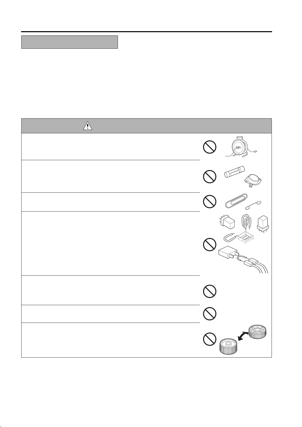
Using any cables or power cord not specified by hp.
•
Using any fuse or thermostat not specified by hp. Safety will not be
•
assured, leading to a risk of fire and injury.
service network.
have to be taken into consideration, with the aim of arriving at proper tolerances and safety
DANGER : PROHIBITED ACTIONS
• Disabling fuse functions or bridging fuse terminals with wire, metal clips, sol-
der or similar object.
• Disabling relay functions (such as wedging paper between relay contacts)
• Disabling safety functions (interlocks, safety circuits, etc.) Safety will not be
assured, leading to a risk of fire and injury.
Making any modification to the MFP unless instructed by hp
•
Using parts not specified by hp
•
S-2
Page 11
SAFETY AND IMPORTANT WARNING ITEMS
2. CHECKPOINTS WHEN PERFORMING ON-SITE SERVICE
HP MFP's are extensively tested before shipping, to ensure that all applicable safety standards are met, in order
to pro-
tect the customer and customer engineer (hereafter called the CE) from the risk of injury. However, in daily
use, any electri-cal equipment may be subject to parts wear and eventual failure. In order to maintain safety
and reliability, the CE mustperform regular safety checks.
2.1 Power Supply
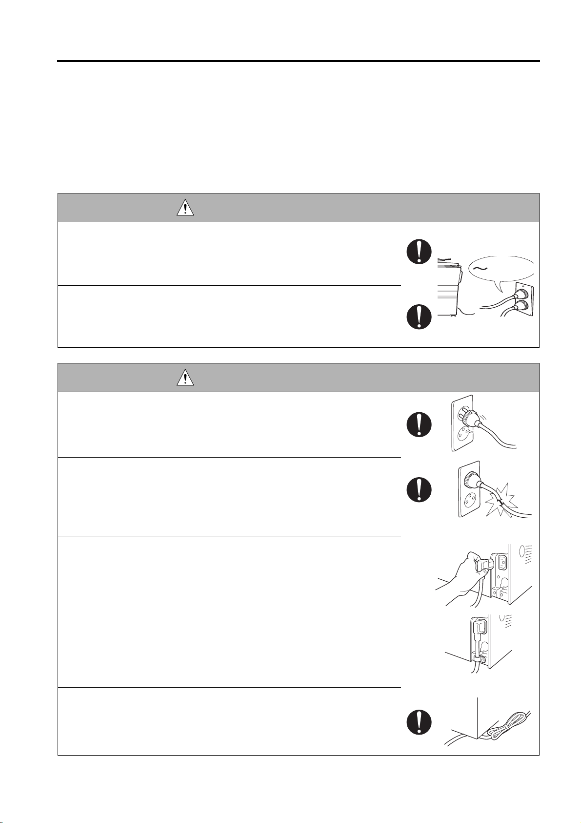
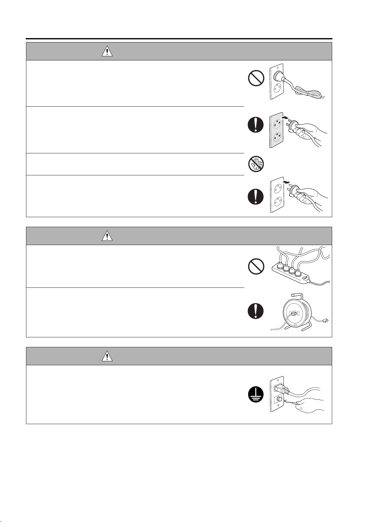
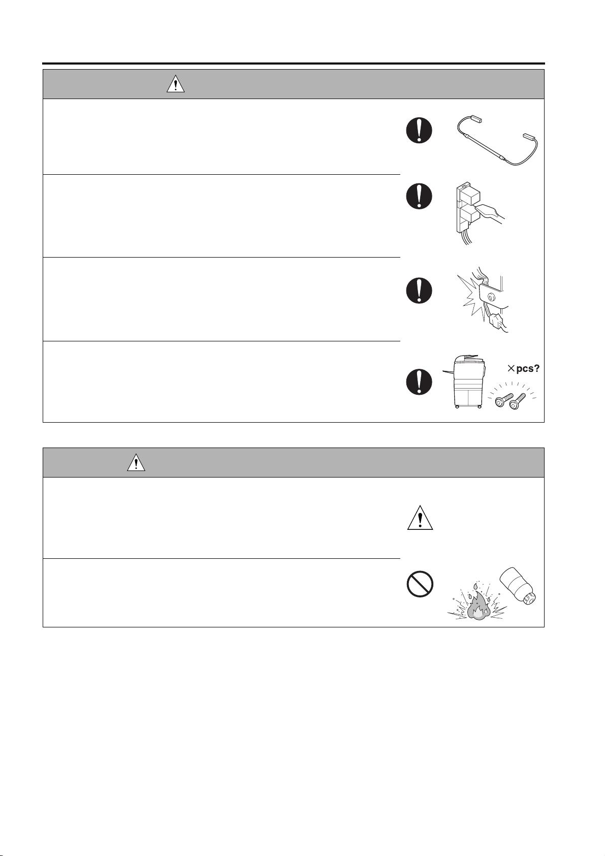
WARNING: Wall Outlet
Check that main voltage is as specified. Plug the power cord into the dedi-
•
cated wall outlet with a capacity greater than the maximum power consump-
tion.
If excessive current flows in the wall outlet, fire may result.
• If two or more power cords can be plugged into the wall outlet, the total load
must not exceed the rating of the wall outlet.
If excessive current flows in the wall outlet, fire may result.
kw
WARNING: Power Plug and Cord
• Make sure the power cord is plugged in the wall outlet securely.
Contact problems may lead to increased resistance, overheating, and the
risk of fire.
• Check whether the power cord is damaged. Check whether the sheath is
damaged.
If the power plug, cord, or sheath is damaged, replace with a new power
cord (with plugs on both ends) specified by hp. Using the damaged
power cord may result in fire or electric shock.
When using the power cord (inlet type) that came with this MFP, be sure to
•
observe the following precautions:
Make sure the MFP-side power plug is securely inserted in the socket
a.
on the rear panel of the MFP.
Secure the cord with a fixture properly.
b. If the power cord or sheath is damaged, replace with a new power cord
(with plugs on both ends) specified by hp.
If the power cord (inlet type) is not connected to the MFP securely, a
contact problem may lead to increased resistance, overheating, and risk
of fire.
• Check whether the power cord is not stepped on or pinched by a table and
so on.
Overheating may occur there, leading to a risk of fire.
S-3
Page 12
SAFETY AND IMPORTANT WARNING ITEMS
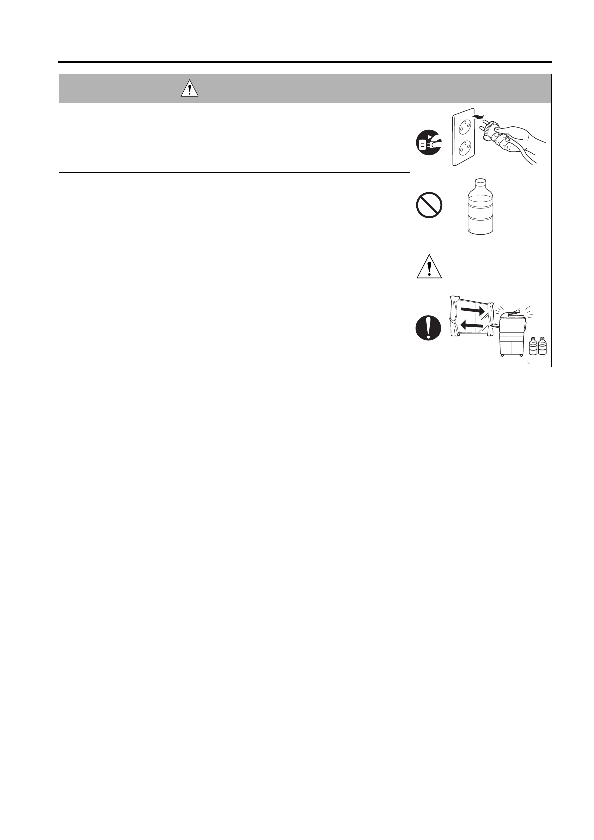
WARNING: Power Plug and Cord
• Do not bundle or tie the power cord.
Overheating may occur there, leading to a risk of fire.
• Check whether dust is collected around the power plug and wall outlet.
Using the power plug and wall outlet without removing dust may result in
fire.
• Do not insert the power plug into the wall outlet with a wet hand.
The risk of electric shock exists.
• When unplugging the power cord, grasp the plug, not the cable.
The cable may be broken, leading to a risk of fire and electric shock.
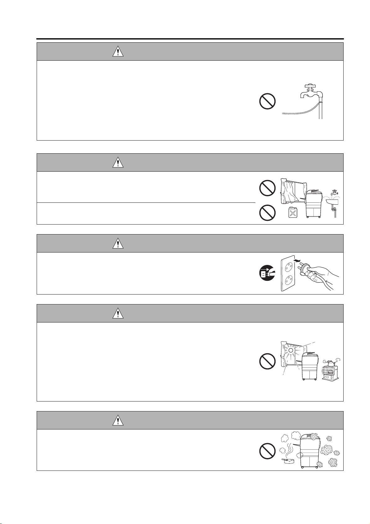
WARNING: Wiring
• Never use multi-plug adapters to plug multiple power cords in the same out-
let.
If used, the risk of fire exists.
• When an extension cord is required, use a specified one.
Current that can flow in the extension cord is limited, so using a too long
extension cord may result in fire.
Do not use an extension cable reel with the cable taken up. Fire may
result.
WARNING: Ground Lead
•
Check whether the MFP is grounded properly.
If current leakage occurs in an ungrounded MFP, you may suffer electric
shock while operating the MFP. Connect the ground lead to one of the
following points:
a. Ground terminal of wall outlet
b. Ground terminal for which Class D work has been done
S-4
Page 13
SAFETY AND IMPORTANT WARNING ITEMS
WARNING: Ground Lead
• Pay attention to the point to which the ground lead is connected.
Connecting the ground lead to an improper point such as the points listed
below results in a risk of explosion and electric shock:
a. Gas pipe (A risk of explosion or fire exists.)
b. Lightning rod (A risk of electric shock or fire exists.)
c. Telephone line ground (A risk of electric shock or fire exists in the case
of lightning.)
d. Water pipe or faucet (It may include a plastic portion.)
2.2. Installation Requirements
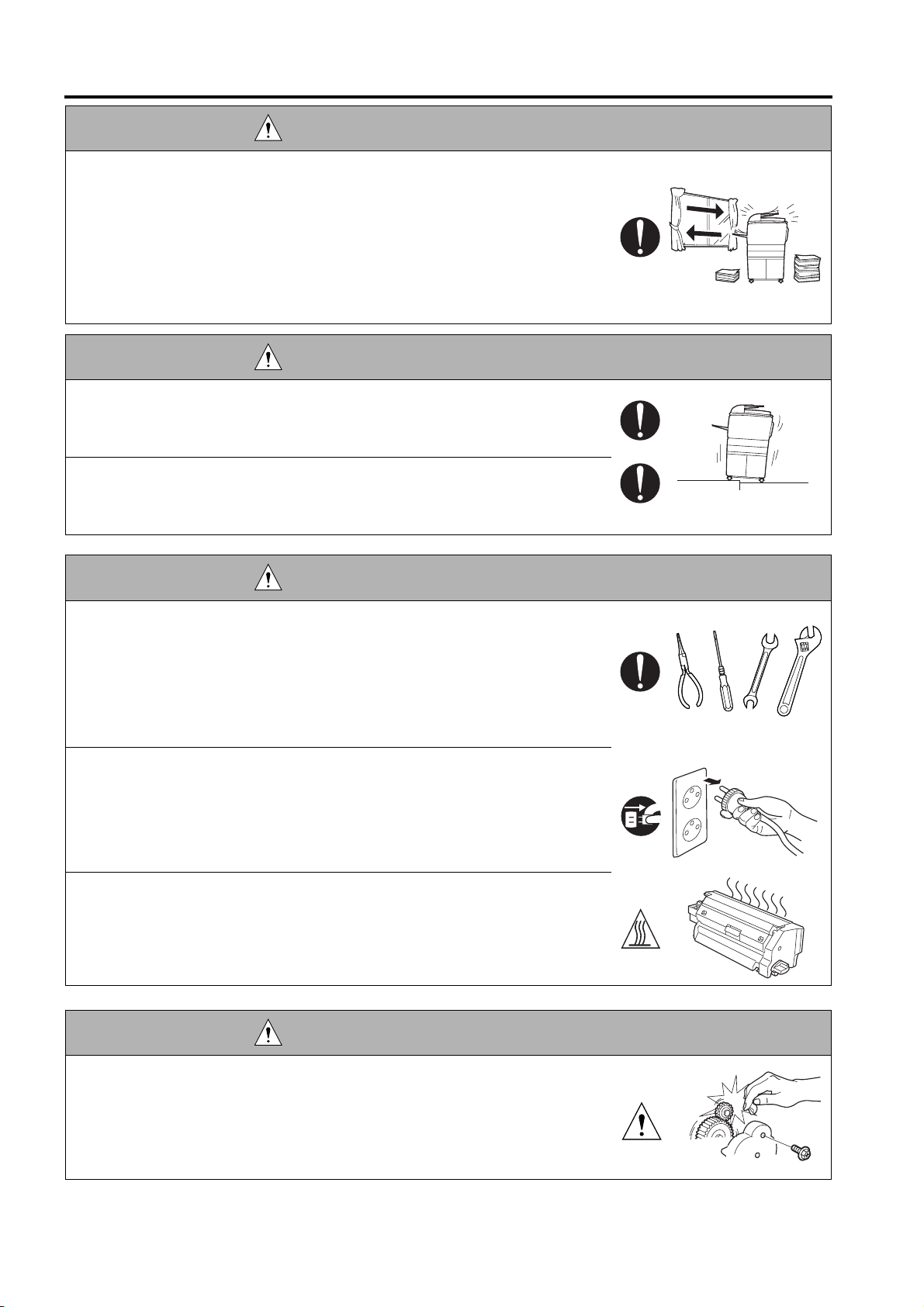
WARNING: Prohibited Installation Place
•
Do not place the MFP near flammable materials such as curtains or volatile
materials that may catch fire.
A risk of fire exists.
Do not place the MFP in a place exposed to water such as rain water.
•
A risk of fire and electric shock exists.
WARNING: Nonoperational Handling
•
When the MFP is not used over an extended period of time (holidays, etc.),
switch it off and unplug the power cord.
Dust collected around the power plug and outlet may cause fire.
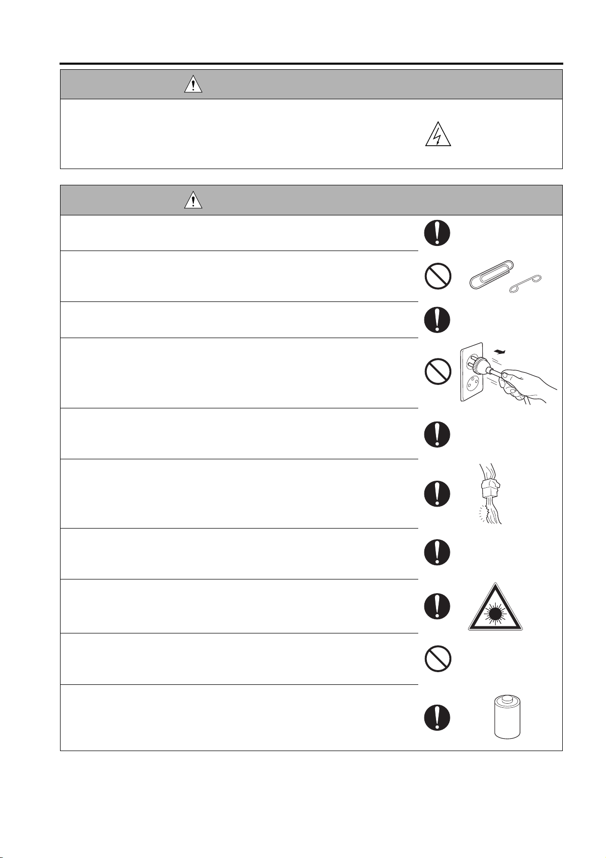
CAUTION: Temperature and Humidity
•
Do not place the MFP in a place exposed to direct sunlight or near a heat
source such as a heater.
A risk of degradation in MFP performance or deformation exists.
Do not place the MFP in a place exposed to cool wind.
Recommended temperature and humidity are as follows:
Temperature: 10
Humidity: 10% to 80% (no dew condensation)
Avoid other environments as much as possible.
°C
to 30
°C
CAUTION: Ventilation
•
Do not place the MFP in a place where there is much dust, cigarette
smoke, or ammonia gas.
Place the MFP in a well ventilated place to prevent engine problems
and image faults.
S-5
Page 14
SAFETY AND IMPORTANT WARNING ITEMS
CAUTION: Ventilation
•
The MFP generates ozone gas during operation, but it is not sufficient to be
harmful to the human body.
If a bad smell of ozone is present in the following cases, ventilate the
room.
a. When the MFP is used in a poorly ventilated room
b. When taking a lot of copies
c. When using multiple MFPs at the same time
CAUTION: Vibration
•
When installing the MFP, read the Installation Guide thoroughly. Be sure to
install the MFP in a level and sturdy place.
Constant vibration will cause problems.
• Be sure to lock the caster stoppers.
In the case of an earthquake and so on, the MFP may slide, leading to a
injury.
CAUTION: Inspection before Servicing
• Before conducting an inspection, read all relevant documentation (service
manual, technical notices, etc.) and proceed with the inspection following
the prescribed procedure in safety clothes, using only the prescribed tools.
Do not make any adjustment not described in the documentation.
If the prescribed procedure or tool is not used, the MFP may break and a
risk of injury or fire exists.
• Before conducting an inspection, be sure to disconnect the power plugs from
the MFP and options.
When the power plug is inserted in the wall outlet, some units are still pow-
ered even if the POWER switch is turned OFF. A risk of electric shock
exists.
• The area around the fixing unit is hot.
You may get burned.
DANGER: Work Performed with the MFP Powered
• Take every care when making adjustments or performing an operation check
with the MFP powered.
If you make adjustments or perform an operation check with the external
cover detached, you may touch live or high-voltage parts or you may be
caught in moving gears or the timing belt, leading to a risk of injury.
S-6
Page 15
SAFETY AND IMPORTANT WARNING ITEMS
DANGER: Work Performed with the MFP Powered
• Take every care when servicing with the external cover detached.
High-voltage exists around the drum unit. A risk of electric shock exists.
WARNING: Safety Checkpoints
• Check the exterior and frame for edges, burrs, and other damages.
The user or CE may be injured.
• Do not allow any metal parts such as clips, staples, and screws to fall into the
MFP.
They can short internal circuits and cause electric shock or fire.
• Check wiring for squeezing and any other damage.
Current can leak, leading to a risk of electric shock or fire.
• When disconnecting connectors, grasp the connector, not the cable.
(Specifically, connectors of the AC line and high-voltage parts)
Current can leak, leading to a risk of electric shock or fire.
• Carefully remove all toner remnants and dust from electrical parts and elec-
trode units such as a charging corona unit.
Current can leak, leading to a risk of MFP trouble or fire.
• Check high-voltage cables and sheaths for any damage.
Current can leak, leading to a risk of electric shock or fire.
• Check electrode units such as a charging corona unit for deterioration and
sign of leakage.
Current can leak, leading to a risk of trouble or fire.
• Before disassembling or adjusting the write unit incorporating a laser, make
sure that the power cord has been disconnected.
The laser light can enter your eye, leading to a risk of loss of eyesight.
• Do not remove the cover of the write unit. Do not supply power with the write
unit shifted from the specified mounting position.
The laser light can enter your eye, leading to a risk of loss of eyesight.
• When replacing a lithium battery, replace it with a new lithium battery speci-
fied in the Parts Guide Manual. Dispose of the used lithium battery using the
method specified by local authority.
Improper replacement can cause explosion.
S-7
Page 16
SAFETY AND IMPORTANT WARNING ITEMS
WARNING: Safety Checkpoints
• After replacing a part to which AC voltage is applied (e.g., optical lamp and
fixing lamp), be sure to check the installation state.
A risk of fire exists.
• Check the interlock switch and actuator for loosening and check whether the
interlock functions properly.
If the interlock does not function, you may receive an electric shock or be
injured when you insert your hand in the MFP (e.g., for clearing paper
jam).
• Make sure the wiring cannot come into contact with sharp edges, burrs, or
other pointed parts.
Current can leak, leading to a risk of electric shock or fire.
• Make sure that all screws, components, wiring, connectors, etc. that were
removed for safety check and maintenance have been reinstalled in the orig-
inal location. (Pay special attention to forgotten connectors, pinched cables,
forgotten screws, etc.)
A risk of MFP trouble, electric shock, and fire exists.
DANGER: HANDLING OF SERVICE MATERIALS
• Toner and developer are not harmful substances, but care must be taken not
to breathe excessive amounts or let the substances come into contact with
eyes, etc. It may be stimulative.
If the substances get in the eye, rinse with plenty of water immediately.
When symptoms are noticeable, consult a physician.
• Never throw the used cartridge and toner into fire.
You may be burned due to dust explosion.
S-8
Page 17
SAFETY AND IMPORTANT WARNING ITEMS
DANGER : HANDLING OF SERVICE MATERIALS
• Unplug the power cord from the wall outlet.
Drum cleaner (isopropyl alcohol) and roller cleaner (acetone-based) are
highly flammable and must be handled with care. A risk of fire exists.
•
Do not replace the cover or turn the MFP ON before any solvent remnants
on the cleaned parts have fully evaporated.
A risk of fire exists.
• Use only a small amount of cleaner at a time and take care not to spill any
liquid. If this happens, immediately wipe it off.
A risk of fire exists.
• When using any solvent, ventilate the room well.
Breathing large quantities of organic solvents can lead to discomfort.
3. MEASURES TO TAKE IN CASE OF AN ACCIDENT
•
If an accident has occurred, the distributor who has been notified first must immediately take emergency
measures toprovide relief to affected persons and to prevent further damage.
If a report of a serious accident has been received from a customer, an on-site evaluation must be carried
•
out quicklyand hp must be notified.
To determine the cause of the accident, conditions and materials must be recorded through direct on-site
•
checks, inaccordance with instructions issued by hp.
For reports and measures concerning serious accidents, follow the regulations given in “Serious
•
Accident Report/Follow-up Procedures”.
4. CONCLUSION
•
Safety of users and customer engineers depends highly on accurate maintenance and administration.
Therefore,safety can be maintained by the appropriate daily service work conducted by the customer
engineer.
•
When performing service, each MFP on the site must be tested for safety. The customer engineer must
verify thesafety of parts and ensure appropriate management of the equipment.
S-9
Page 18

SAFETY AND IMPORTANT WARNING ITEMS
SAFETY INFORMATION
IMPORTANT INFORMATION
The Center for Devices and Radiological Health (CDRH) of the U.S. Food and Drug Administration implemented
regulations for laser products manufactured since August 1, 1976. Compliance is mandatory for products mar-
keted in the United States.
This MFP is certified as a “Class 1” laser product under the U.S.
Department of Health and Human Services (DHHS) Radiation Performance Standard according to the Radiation
Control for Health and Safety Act of 1968. Since radiation emitted inside this MFP is completely confined within
protective housings and external covers, the laser beam cannot escape during any phase of normal user opera-
tion.
S-10
Page 19
SAFETY AND IMPORTANT WARNING ITEMS
SAFETY CIRCUITS
This engine is provided with the following safety circuits to prevent engine faults from resulting in serious
accidents.
• Overall protection circuit
Fixing upper lamp 1 (L2), Fixing upper lamp 2 (L3), Fixing lower lamp (L4) overheating prevention circuit
•
These safety circuits are described below to provide the service engineer with a renewed awareness of them in
order to pre-vent servicing errors that may impair their functions.
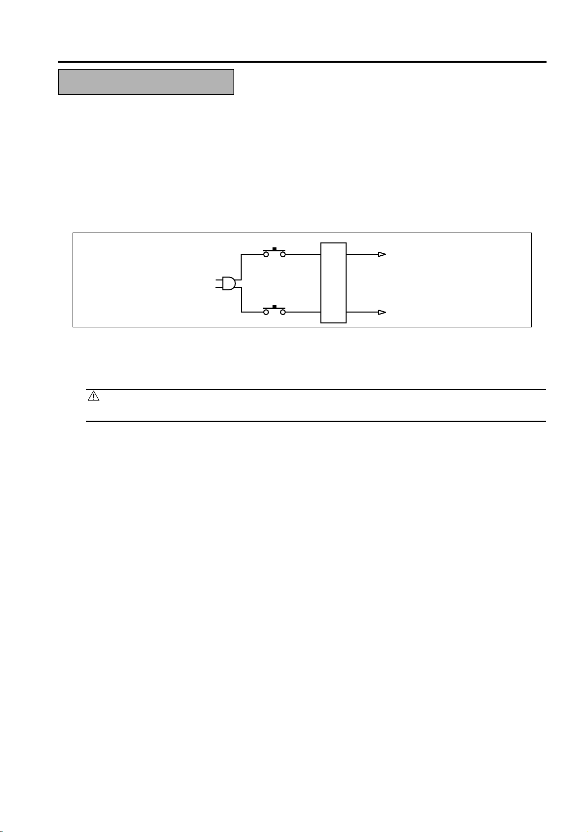
1. Overall protection circuit
CBR1
NF
CBR2
1.1 Protection by circuit breaker /1 (CBR1) and circuit breaker /2 (CBR2)
CBR1 and CBR2 interrupt the AC line instantaneously when an excessive current flows due to a short
in the ACline.
CAUTION:
The CBR1 and CBR2 functions must not be deactivated under any circumstances.
S-11
Page 20
SAFETY AND IMPORTANT WARNING ITEMS
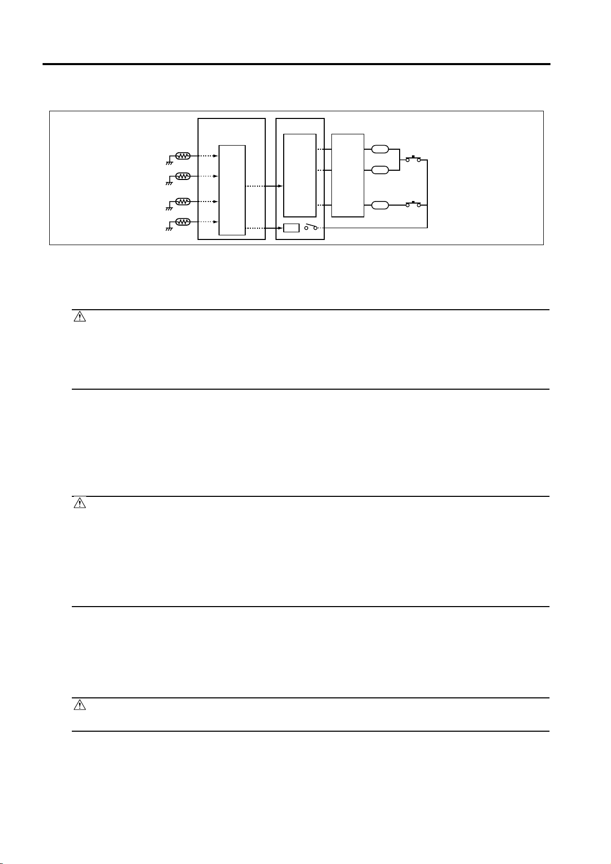
2.
Fixing upper lamp 1 (L2), Fixing upper lamp 2 (L3), Fixing lower lamp (L4) overheating
prevention circuit
PRCB ACDB
TH1
TH3
TH2
TH4
Control
section
AC driver
section
RL1
RL1
FHCB
L2
TS1
L3
TS2
L4
2.1 Protection by software
The output voltage from fixing temperature sensor 1 (TH1) and fixing temperature sensor 2 (TH2) is
read by theCPU. If this voltage is abnormal, L2, L3, and L4 are turned OFF by opening main relay (RL1).
CAUTION:
The clearance between the fixing upper roller and TH1 and the clearance between the fixing
•
lower roller and TH2 must not be changed. When replacing them, make sure to comply with
the specified clearances.
• The RL1 function must not be deactivated under any circumstances.
2.2 Protection by the hardware circuit
The output voltages from fixing temperature sensor 1 (TH1), fixing temperature sensor 2 (TH2), fixing
temperaturesensor 3 (TH3), and fixing temperature sensor 4 (TH4) are compared with the abnormality
judgment referencevalue in the comparator circuit. If the output voltage from TH1, TH2, TH3, or TH4
exceeds the reference value, L2,L3, and L4 are turned OFF by opening RL1.
CAUTION:
• The clearance between the fixing upper roller and TH1 and the clearance between the fixing
lower roller and TH2 must not be changed. When replacing them, make sure to comply with
the specified clearances.
• Periodically check the contact between the fixing upper roller and TH3 and the contact
between the fixing lower roller and TH4, and replace them if any abnormality is detected.
• The RL1 function must not be deactivated under any circumstances.
2.3
Protection by thermostat 1 (TS1) and thermostat 2 (TS2)
When the temperature of the fixing upper roller exceeds the specified value, TS1 is turned OFF, thus
interrupting thepower to L2 and L3 directly. When the temperature of the fixing lower roller exceeds the
specified value, TS2 isturned OFF, thus interrupting the power to L4 directly.
CAUTION:
Do not use any other electrical conductor in place of TS1 and TS2.
S-12
Page 21
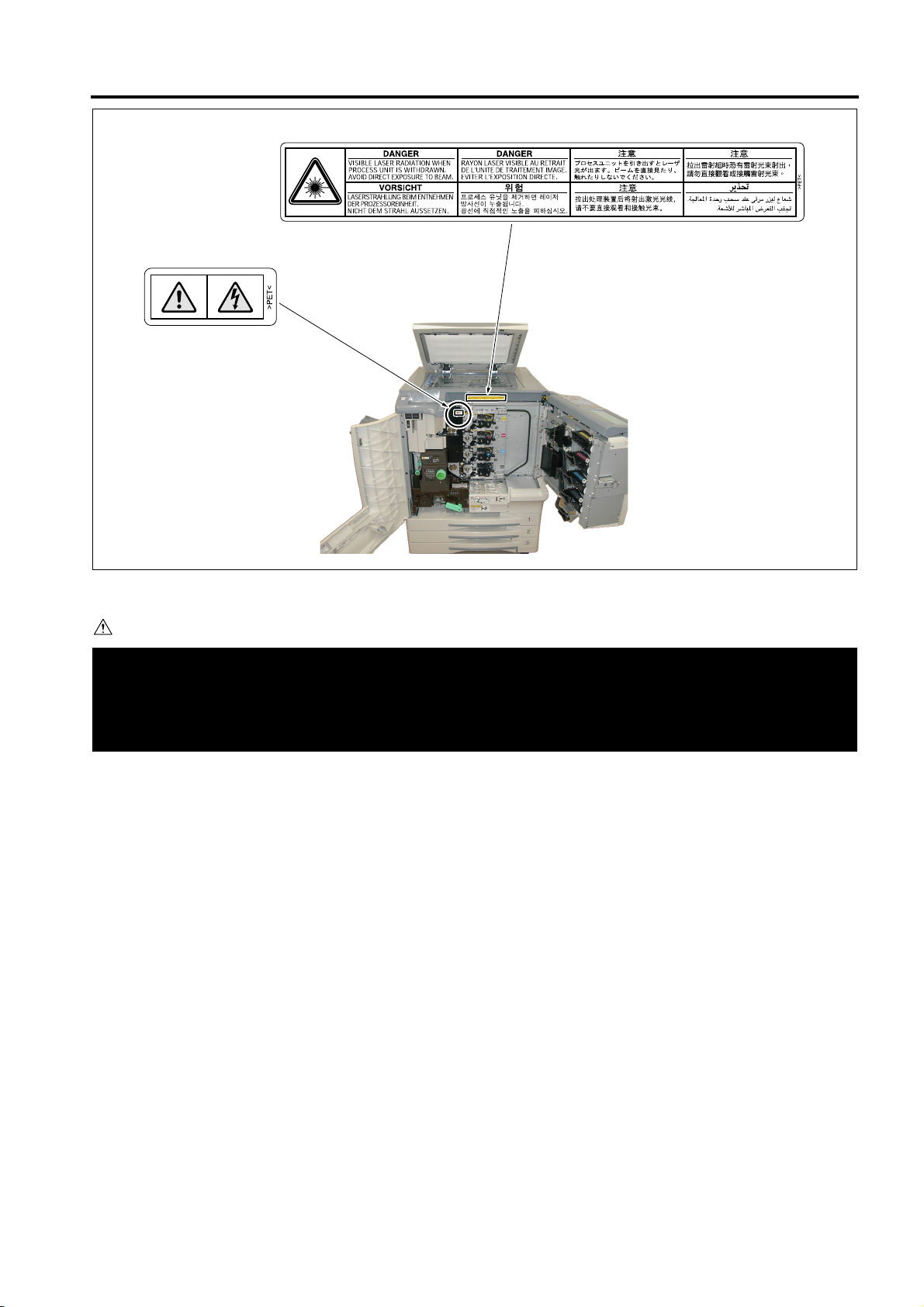
SAFETY AND IMPORTANT WARNING ITEMS
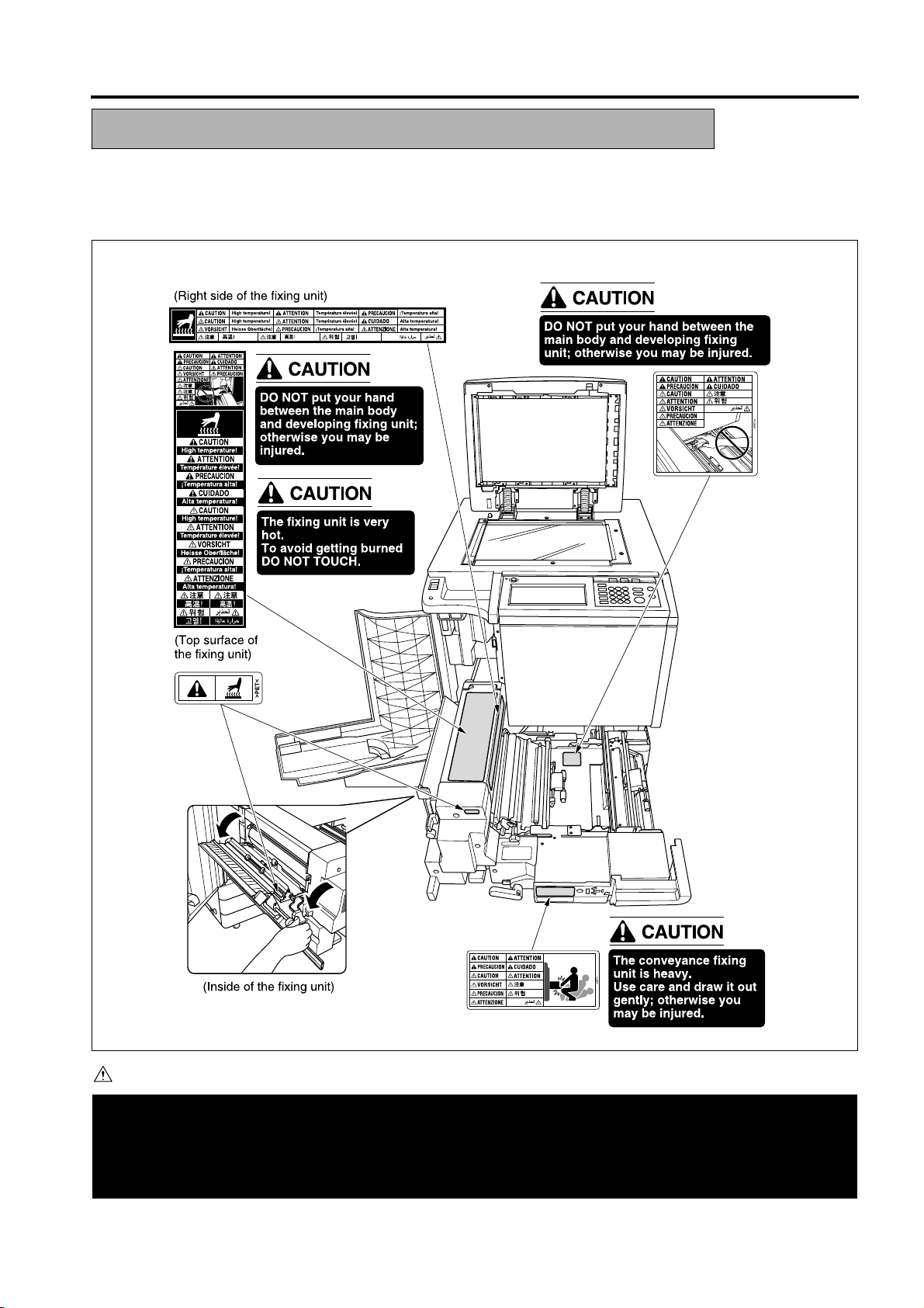
INDICATION OF WARNING ON THE ENGINE
Caution labels shown below are attached in some areas on/in the engine.
When accessing these areas for maintenance, repair, or adjustment, special care should be taken to avoid
burns and electricshock.
CAUTION
You may be burned or injured if you touch any area that you are advised by any caution label to keep your-
self away from.
Do not remove caution labels. If any caution label has come off or soiled and therefore the caution cannot
be read, contact our Service Office.
S-13
Page 22
SAFETY AND IMPORTANT WARNING ITEMS
(Right rear side of the ADF)
(Right rear side
of the Engine)
(Inside of the HCI)
HCI
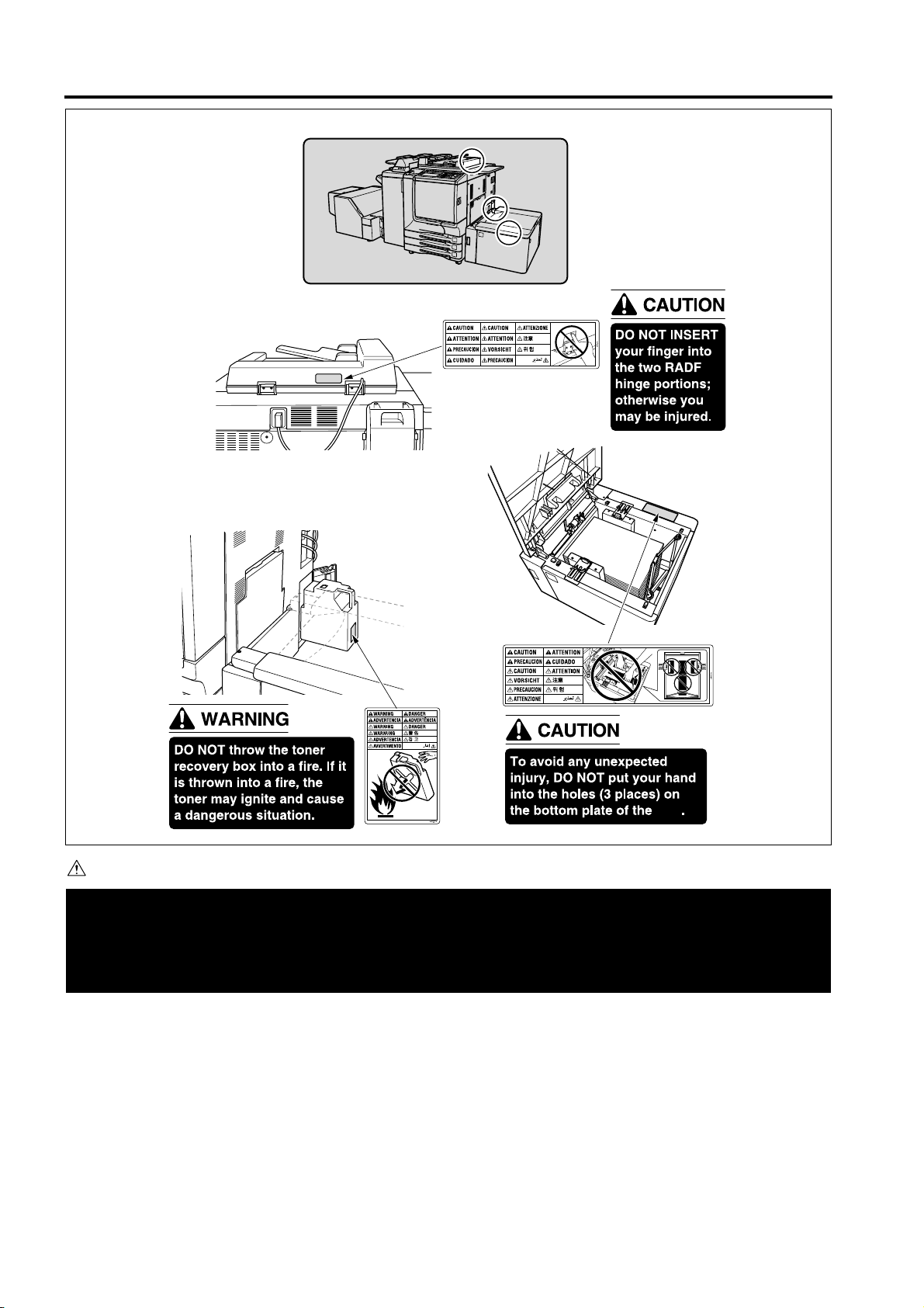
CAUTION
You may be burned or injured if you touch any area that you are advised by any caution label to keep your-
self away from.
Do not remove caution labels. If any caution label has come off or soiled and therefore the caution cannot
be read, contact our Service Office.
S-14
Page 23
Q3636A
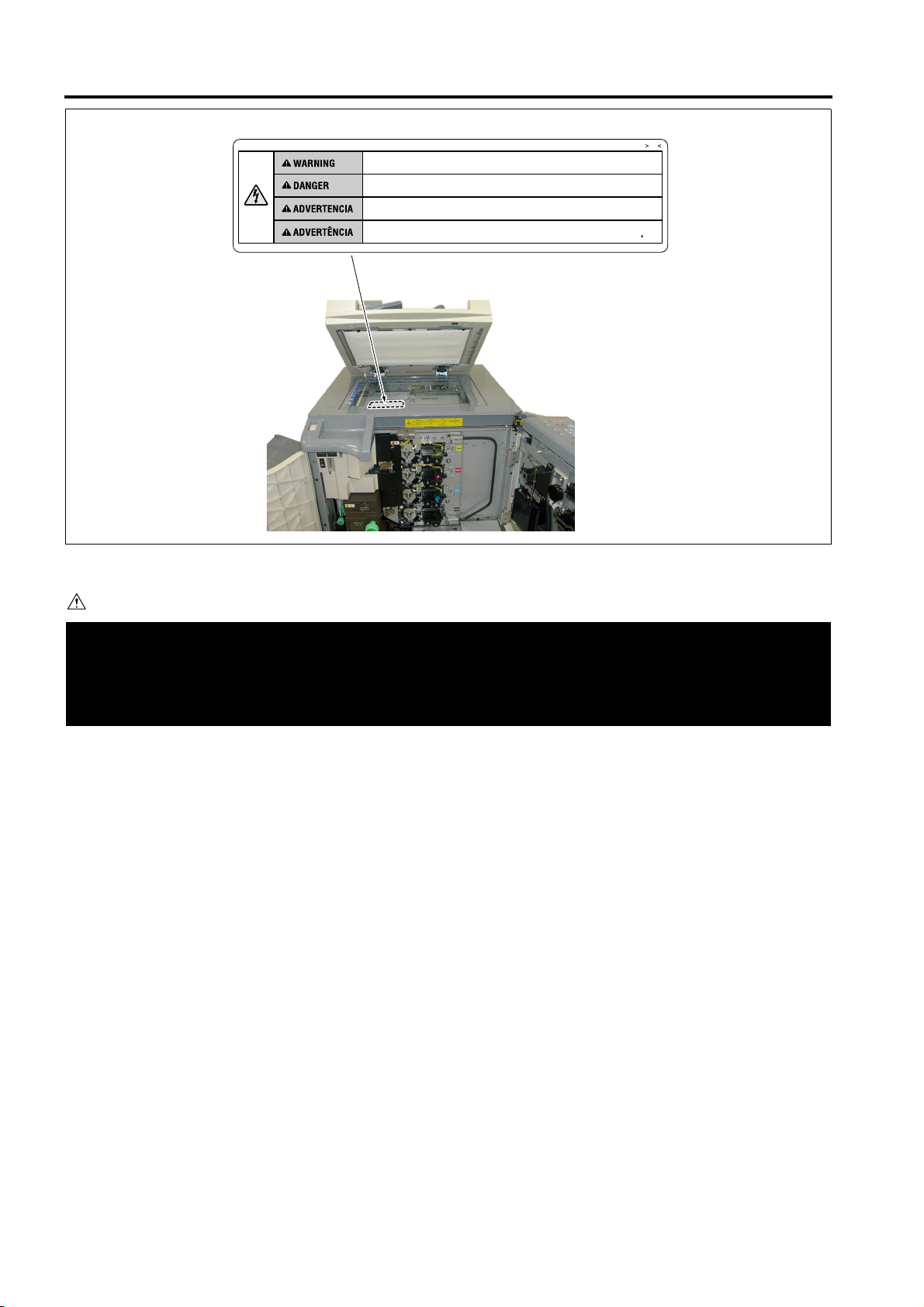
SAFETY AND IMPORTANT WARNING ITEMS
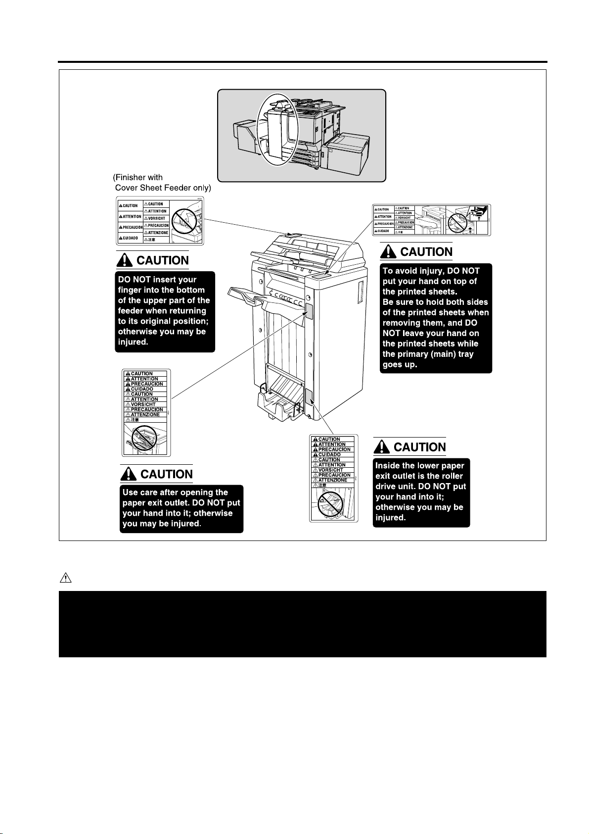
CAUTION
You may be burned or injured if you touch any area that you are advised by any caution label to keep your-
self away from.
Do not remove caution labels. If any caution label has come off or soiled and therefore the caution cannot
be read, contact our Service Office.
S-15
Page 24
SAFETY AND IMPORTANT WARNING ITEMS
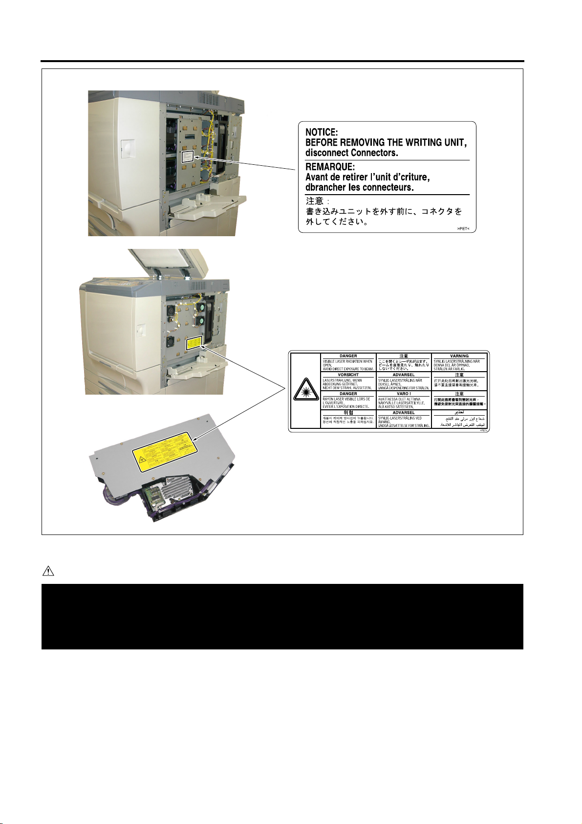
CAUTION
You may be burned or injured if you touch any area that you are advised by any caution label to keep your-
self away from.
Do not remove caution labels. If any caution label has come off or soiled and therefore the caution cannot
be read, contact our Service Office.
S-16
Page 25
SAFETY AND IMPORTANT WARNING ITEMS
CAUTION
You may be burned or injured if you touch any area that you are advised by any caution label to keep your-
self away from.
Do not remove caution labels. If any caution label has come off or soiled and therefore the caution cannot
be read, contact our Service Office.
S-17
Page 26
SAFETY AND IMPORTANT WARNING ITEMS
Unplug the engine before removing scanner glass.
Debrancher le copieur avant de retirer la vitre d'exposition.
Desenchufe la maquina antes de quitar el vidrio.
Desconecte a unidade da tomada antes de remover o vidro de exposicao.
PS
~
CAUTION
You may be burned or injured if you touch any area that you are advised by any caution label to keep your-
self away from.
Do not remove caution labels. If any caution label has come off or soiled and therefore the caution cannot
be read, contact our Service Office.
S-18
Page 27

hp Color 9850mfp
I Product information
1.1 Product features
HP Color 9850mfp (Q3225A) basic configuration
The HP Color 9850mfp comes standard with 128-MB RAM for each color, wideformat standalone copying capability, trays 1, 2 and 3 (500-sheets each), a 250sheet multipurpose bypass tray and a Reversing Automatic Document Feeder
RADF.
HP Color 9850mfp (Q3225A) fully loaded
The fully loaded HP Color 9850mfp comes with 384-MB RAM for each color, a 20GB EIO hard disk, wide-format printing, copying and network printing capabilities,
trays 1, 2 and 3 (500-sheets each), a 250-sheet multipurpose bypass tray, tray 4
(a 2,500-sheet high capacity input HCI), a Reversing Automatic Document Feeder
RADF, an EFI print controller, a 3000-sheet Stapler-stacker or a Multifunction
Finisher with a Trimmming Unit at the output, a Post Insertion Unit for feeding
covers, and a Hole Punch Unit at the output.
Table 1. Features of the HP Color 9850mfp
OUTLINE OF SYSTEM
I OUTLINE
Speed
Resolution
Consumables
Language
and fonts
Memory expansion
Functions
Expandability z HP Color 9850mfp automatic document feeder (standard)
z Up to 50/51 pages per minute (ppm) for letter / A4-size media.
z First page out in 7.6 seconds for color and 6 seconds for B/W.
z 600-by-600 dots per inch (dpi).
z
600-by-1800 dots per inch (dpi) enhanced resolution mode (printing only).
z CMYK toner bottles.
z Staple cartridges.
z PCL6 EC (XL)
z PCL6e
z PCL5EC (with color)
z PCL6E (XL)
z PJL
Post Script 3
z
Basic 128 MB of RAM per color, expandable to 384 MB by using hp 256
z
MB memory module (Q6993A).
z Bypass tray supports up to 200 sheets of 28 lbs of custom-sized media up
to 13 by 19 in. (250 sheets of 20 lbs)
z Trays 1, 2 and 3 support up to 400 sheets of 28 lbs (500 sheets of 20 lbs)
Tray 4 supports up to 2,200 sheets of 28 lbs (2,500 sheets of 20 lbs)
z
z Two-sided printing (duplex printing)
z Wide-format printing
z Glossy printing
z Document finishing options (with stapler-stacker or multifunction finisher).
z 3,000-sheet stapler/stacker (optional)
z 3,000-sheet Multifunction finisher (optional)
z 4 DIMM slots for adding memory (standard)
z 20 GB hard disk drive (optional)
Wireless printing
Interface connection
z Not supported
Video interface for EFI print controller
z
z Parallel port (based on IEEE 1284, for service)
z Serial port (USB Type B, for service)
z RJ45 Ethernet connector (available with EFI print controller)
1-1
Page 28

PRODUCT SPECIFICATIONS hp Color 9850mfp
Table 1. Features of the HP Color 9850mfp (continued)
Networking
Maximum monthly duty cycle z 150,000 pages per month
z EFI print controller
I OUTLINE
1.2 Product specifications
Identification
A user-accessible label is located on the back cover of the engine. The model number is
alphanumeric, such as Q3225A.
The serial number contains information about the country of origin, product type, engine voltage,
revision number, and engine serial number. An example of a serial number is JPHCB00001. Please
refer to the 9850mfp Parts Manual, section How to use this manual for detailed information.
The identification label also contains electrical information and regulatory information.
Note The electrical information and regulatory information vary by country/region.
Specifications
Type:
Copying method: Tandem intermediate transfer type electrostatic method
Original table: Fixed
Original alignment: Rear left side as reference
Photosensitive material: OPC
Sensitizing method:
Paper feed trays: 3 trays method (500 sheets x 3, 80 to 90g/m
Console type (floor-mounted type)
Laser writing
Multisheet by-pass tray (250 sheets, 80 to 90g/m
Q5690A (2500 sheets, 80 to 90g/m , optional)
2
2
) (400 sheets x 3, 105g/m2)
2
) (200 sheets, 105g/m2)
WARNING!
Table 2. HP Color 9850mfp specifications
Specification Out-of-box Packaged
Height 1,179 mm (46.4 inches) 1,210 mm (47.6 inches)
Width 1,275 mm (50.2 inches) 950 mm (37.4 inches)
Depth 889 mm (35.0 inches) 1,258 mm (49.5 inches)
Weight
313 kg (690 lb) 361 kg (796 lb)
Table 3. Power requirements and circuit capacity
Power source for inch area Power source for metric area
Power requirements
Minimum recommended
circuit capacity
208 to 240 V (+/- 10%)
60 Hz 50 Hz
3600 Watts (dedicated circuit) 3450 Watts (dedicated circuit)
230 V, -14% +10.6%
Power requirements are based on the country/region where the MFP is sold. Do not convert operating
voltages. This can damage the MFP and void the product warranty.
1-2
Page 29

hp Color 9850mfp
Table 4. Power consumption
OUTLINE OF SYSTEM
MFP state
Switch off mode
Sleep mode
Low power mode
Continuous copying mode (A4) 1,618 W 1,603 W
Inch area consumption
0.2 W
12 W
172.4 W
568 WIdling mode
Metric area consumption
0.2 W
11 W
178.8 W
548 W
Environmental specifications
The environmental specifications must be maintained to ensure the proper operation of the MFP.
Consider the following points before installing the MFP:
z Install the MFP in a well-ventilated, dust-free area.
z Install the MFP on a level, flat surface that can support its size and weight. Do not install on
carpet or on other soft surfaces. Make sure that all four MFP feet are level.
z Install the MFP where temperature and humidity are stable, with no abrupt changes (away from
water sources, humidifiers, air conditioners, refrigerators, or other major appliances).
z Install the MFP away from direct sunlight, areas that experience vibration, open flames,
ammonia fumes, ultrasonic heaters, and devices that emit a magnetic field. If the MFP is
placed near a window, make sure that the window has a curtain or blind to block direct sunlight.
z Maintain enough space around the MFP for proper access and ventilation.
z Be sure to use a power source of the voltage and frequency indicated in the product
specifications. Ensure that the current carrying capacity of the power outlet is at least equal to
the current listed in the product specifications.
z Power the machine directly from a dedicated power outlet. (Do not use an extension cord.)
z Do not plug or unplug the power cord with wet or dirty hands, to prevent an electric shock.
I OUTLINE
Note
Table 5. Environmental specifications
Allowable condition Recommended condition
Operating temperature 10 to 30 C elsius (C)
(50 to 86 Fahrenheit [F])
Relative humidity 10 to 80 percent 40 to 60 percent
18 to 23 C (64 to 73 F)
Table 6. Noise level specifications
Acoustics Printing (50 ppm) Low power mode
Sound power level L
Sound pressure level, L
(Bystander position)
pAm
L
WAd
pAm
= 59 dB(A)
essentially inaudible = 7.7 B(A)
essentially inaudible
Testing per International Standards Organization (ISO) 9296 and (ISO) 7779.
1-3
Page 30
PRODUCT SPECIFICATIONS hp Color 9850mfp
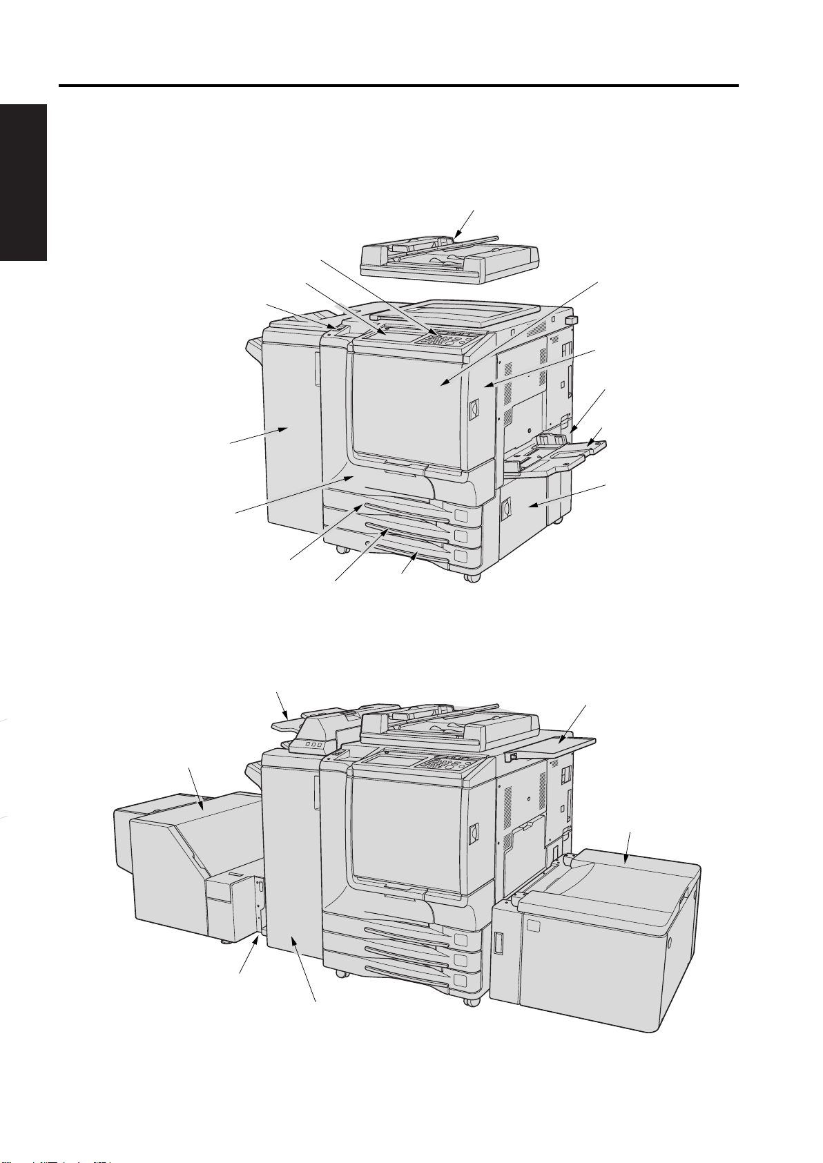
1.3 Product overview
External assembly locations
I OUTLINE
Control panel
LCD Touch screen
Power switch
Stapler/stacker
(option)
RADF
Toner supply unit
Toner access door
Toner recovery box
Multi-sheet
bypass tray
Trimmer unit
(option)
Front door
Tray 1
Cover insertion kit
(option)
Tray 2
Right side door
Tray 3
Work table
Tray 4 ( HCI High
capacity input) (option)
Trimmer kit (option)
Multifunction Finisher (option)
1-4
Page 31

hp Color 9850mfp
OUTLINE OF SYSTEM
Accessories
1
Standard/optional equipment
I OUTLINE
2
3
4
5
7
6
8
9
11
10
12
13
1
HP 3 Hole Punch Kit
2
HP Post Insertion Kit
3
HP Automatic Document Feeder (RADF (ADF))
4Work table
5 HP 3000-Sheet Stapler/Stacker
6
HP Color 9850mfp (engine)
7 HP 2500-Sheet High Capacity Input (HCI)
8 HP 256 MB Memory Module
9 HP Copy Controller Hard Drive
10
HP 3000-Sheet Multifunction Finisher
11
EFI Print Controller Kit
12
HP Trimmer Adapter Kit connects the Finisher and HP Trimmer Unit.
13
HP Trimmer Unit
1-5
Page 32

PRODUCT SPECIFICATIONS hp Color 9850mfp
Internal engine parts
I OUTLINE
1
Lever A can be moved to withdraw the ADU for removal of misfed paper.
Fixing unit fuses the toner onto the copy paper.
2
3 Main power switch (used only by a service representative) turns the engine
power on and off.
4 Total counter indicates the total number of prints made.
5 Black print counter indicates the total number of the black prints made.
1.4 Space requirements
Printer with packaging
The shipping box that contains the HP Color 9850mfp is 950 mm (37.4 inches) wide, 1,258 mm
(49.5 inches) deep and 1,210 mm (47.6 inches) high. The in-box weight of the HP Color
9850mfp is 361 kg (796 lb) .The customer must locate a door or receiving area that is large
enough to accept delivery of the shipping box.
Note
Before removing the printer from the box, make sure that adequate space is available to
unpack the printer and to roll the product off of the shipping pallet. At least 10 feet of clearance
around the box is required to remove all of the shipping materials.
1-6
Page 33

hp Color 9850mfp
Printer physical dimensions
Install the MFP in an area with adequate space for performing all operations, replacing supply
items, and conducting preventive maintenance.
OUTLINE OF SYSTEM
I OUTLINE
HP Color 9850mfp plus HP Automatic Document
Feeder (Front) and 3000-sheet Stapler/Stacker
HP Color 9850mfp plus HP Automatic Document
Feeder, HP 3000-Sheet Multifunction Finisher,
HP Post Insertion Kit, and HP 2500-Sheet High
Capacity Input (HCI) (Front)
HP Color 9850mfp plus HP Automatic Document
Feeder (Right side)
HP Color 9850mfp plus HP Automatic Document
Feeder and HP 2500-Sheet High Capacity Input (HCI)
(Right side)
HP Color 9850mfp plus HP Automatic Document
Feeder, HP 3000-Sheet Multifunction Finisher,
HP Post Insertion Kit, HP 2500-Sheet High Capacity
Input (HCI), and HP Trimmer Unit, (Front)
1-7
Page 34

PRODUCT SPECIFICATIONS hp Color 9850mfp
1.5 Setup
The initial printer setup includes the following steps:
z Remove the printer from the box.
I OUTLINE
z Set up and install the printer. See the HP Color 9850 Install Guide.
z Set up and install the finishing devices. See the install guide that came with the finishing devices.
The shipping box contains the following items:
z HP Color 9850mfp
z Rear cover
z One Ozone filter
z
Four developers
Black
Yellow
Cyan
Magenta
z One developer charging funnel
z Four developing units
Black
Yellow
Cyan
Magenta
z Nails
z One transfer unit
z One belt cleaner unit
z One separation claw unit
z Three TP M3x6 screws
z One working table (shipped in Tray 2)
z HP Color 9850mfp System Administrator’s Guide
z One manual holder (shipped in Tray 3)
z HP Color 9850mfp Installation Guide
z One primary power switch label
z One secondary power switch label
Note The finishing devices are delivered in separate boxes.
1-8
Page 35

hp Color 9850mfp
1.6 Media specifications
Before purchasing large quantities of print media, make sure that it meets the requirements specified
in this service manual and in the HP Color 9850mfp System Administrator Guide. Always test the
print media before buying large quantities.
Hewlett-Packard neither warrants nor recommends the use of a particular brand of paper or print
media other than HP media. Media properties are subject to manufacturing changes, and HP has no
control over such changes. Although testing the media helps to characterize the performance and
the manufacturers process quality, the customer assumes all responsibility for the quality and
performance of media.
CAUTION
Using print media that does not meet HP specifications might cause problems for the printer,
requiring repair. Such repair is not covered by the Hewlett-Packard warranty or service
agreements.
The HP Color 9850mfp accepts a variety of media, such as cut-sheet paper, labels, and customsize paper. Properties such as weight, composition, grain, and moisture content are important
factors affecting printer performance and output quality. Media that does not meet the guidelines
outlined in this manual and in the print media guide can cause the following problems:
z poor print quality
z increased jams
z premature wear on the printer, requiring repair
OUTLINE OF SYSTEM
I OUTLINE
Note
Hint
Guidelines for selecting media
Selecting media by type and size at the control panel and in the MFP must be selected prior
to print/copy. Using the wrong setting can result in unsatisfactory print quality. Always print
by type for special print media such as labels.
Some print media might meet all of the guidelines in this manual and still not produce satisfactory
results. This might be the result of improper handling, unacceptable temperature and humidity
levels, or other variables over which HP has no control.
If you are unsure what type of paper you are loading (such as bond or recycled), check the label on
the package of paper.
See Basis weight field test on page 1-15 for information about measuring basis weight.
z
See Caliper field test on page 1-17 for information about measuring caliper.
z
See Paper finish field test on page 1-17 for information about smoothness.
z
Do not purchase more media than can be easily used in a short time (about 3 months). Media
that is stored for long periods experiences heat and moisture extremes that can be damaging.
Planning is important to prevent damage to a large supply of media.
1-9
Page 36

PRODUCT SPECIFICATIONS hp Color 9850mfp
Supported media and capacity for input and output
Note The leading edge is listed first in the dimension measurements.
Table 7. Supported standard media sizes
I OUTLINE
Bypass tray Tray 4 / HCIPrinting task Trays 1, 2 and 3
Simplex, and duplex
letter, letter R, legal,
z z
5.5 x 8.5R, A3, A4, A4R
A5R, B4, B5, B5R,
11 by 17, 12 by 18,
and 13 by 19 inches
zletter, letter R, legal,
5.5 x 8.5R, A3, A4
A4R, A5R, B4, B5,
B5R, B6R, 11 by 17,
12 by 18, 13 by 19 in
letter, letter R,
legal, A3, A4,
B4, B5, 11 by 17,
12 by 18 and 13
by 19 inches
Table 8. Maximum custom sizes
Printing task Trays 1, 2 and 3 Bypass tray Tray 4 / HCI
Simplex, and duplex
330 by 487 mm
z z
(13 by 19.2 inches)
z 330 by 487 mm
330 by 487 mm
(13 by 19.2 inches)(13 by 19.2 inches)
Table 9. Minimum custom sizes
Printing task Trays 1, 2 and 3 Bypass tray Tray 4 / HCI
Simplex and duplex
z210 by 140 mm
( 8.27 by 5.51 inches)
z100 by 148 mm
(3.9 by 5.8 inches)
z 257 by 210 mm
(10.1 by 8.3 inches)
Table 10. Supported media weights
Printing task Trays 1, 2 and 3 Bypass tray Tray 4 / HCI
Simplex and duplex
64 to 209 g/m
z
(17- to 115-lb)
2
64 to 256 g/m 64 to 256 g/m
z
(17- to 143-lb) (17- to 143-lb)
2
z
Table 11. Input tray capacities
2
CAUTION
Type of media Trays 1, 2 and 3 Bypass tray Tray 4 / HCI
Cut sheets z
Up to 400 sheets
28 lb paper
Up to 200 sheets
28 lb paper
Up to 2,200 sheets
28 lb paper
Table 12. Output bin capacities
2
Bin
Stapler/stacker
Multifunction finisher
Trimmer unit
Exit tray
75 g/m
z Up to 3000 sheets Up to 2400 sheets
z Up to 3000 sheets Up to 2400 sheets
z Up to 500 sheets
z up to 150 sheets
Do not use paper that is heavier than 200 g/m (53-lb bond) for duplex printing. Damage to the
(20-lb bond)
105 g/m (28-lb bond)
Up to 410 sheets
Up to 120 sheets
2
2
printer and jams might result.
Coated paper of 106g/m to 256g/m is fed one at a time by by-pass feed. However, it is possible to
2 2
feed it through H CI (optional).
Double sided copy is unavailable for special paper that is other than the ordinary paper of 105g/m to
200g/m .
2
2
1-10
Page 37

hp Color 9850mfp
Recommended media
The media types that are listed in the following table meet these criteria:
z They have been tested in this printer.
z They have proven to be of good quality.
z They work well with the printers settings.
Ordering recommended media
The product numbers for media are listed in parentheses after the media sizes. Use these product
numbers when ordering media.
OUTLINE OF SYSTEM
I OUTLINE
Note
All of the HP-brand media is available at http://www.hpshopping.com
supplies retailer.
Set the type at the control panel when you load the trays.
Table 13. Recommended media
Recommended media Type Characteristics
HP High Gloss Laser Paper
letter (Q2419A)
11 by 17 (tabloid) (Q2420A)
A3 (Q2422A)
HP Premium Cover Paper
letter (Q2413A)
HP Color Laser Paper
letter (HPL245R)
COATED
106-162 g/m
WEIGHT 4
COATED
209-256 g/m
WEIGHT 6
NORMAL
81-105 g/m
WEIGHT 3
120 g/m2 (32-lb bond), 200 sheets,
high-gloss finish coating on both
sides, 95 bright
Use for: brochures, catalogs, business
plans, photographs, and images
200 g/m
super-smooth matte finish on both
sides, 96 bright
Use for: postcards and document
covers
90 g/m
smooth matte finish on both sides, 96
bright
2
(75-lb cover), 100 sheets,
2
(24-lb bond), 500 sheets,
or from your local office
HP Color Laser Paper
105 g/m
letter (HPL285R)
HP Soft Gloss Laser Paper
A4 (C4179B)
2
(28-lb bond)
NORMAL
81-105 g/m
WEIGHT 3
NORMAL
106-162 g/m
WEIGHT 4
1-11
Use for: newsletters and color
documents
105 g/m
smooth matte finish on both sides, 96
bright
Use for: newsletters and color
documents
120 g/m
satin finish coating on both sides, 96
bright
Use for: flyers, handouts, sales briefs,
proposals, and color images
2
(28-lb bond), 500 sheets,
2
(32-lb bond), 200 sheets,
Page 38

PRODUCT SPECIFICATIONS hp Color 9850mfp
Table 13. Recommended media (continued)
Recommended media Type Characteristics
I OUTLINE
HP Soft Gloss LaserPaper
105 g/m
11 by 17 (tabloid) (Q2416A)
A4 (Q2417A)
HP Premium Choice LaserJet Paper
letter (HPU1132)
11 by 17 (tabloid) (HPU1732)
HP LaserJet Paper
letter (HPJ1124)
legal (HPJ1424)
HP Multipurpose Office Paper
letter (HPC8511)
letter (Q1298A)
letter (HPM1120)
letter (HPA510)
letter (HPP1122) 85 g/m2 (22-lb bond)
legal (HPM1420)
11 by 17 tabloid (HPBC17)
11 by 17 tabloid (HPM1720)
2
(28-lb bond)
NORMAL
81-105 g/m
WEIGHT 4
NORMAL
106-162 g/m
WEIGHT 4
NORMAL
81-105 g/m
WEIGHT 3
NORMAL
75-80 g/m
WEIGHT 4
105 g/m2 (28-lb bond), 500 sheets,
satin finish coating on both sides, 96
bright
Use for: flyers, handouts, sales briefs,
proposals, and color images
120 g/m2 (32-lb bond), 500 sheets
(250 sheets for 11 by 17), matte finish
on both sides, 98 bright
Use for: proposals and charts
2
90 g/m
matte finish on both sides, 96 bright
Use for: reports, user manuals,
letterhead, and correspondence
75 g/m2 (20-lb bond), 500 sheets
Use for: Everyday office documents
(24-lb bond), 500 sheets,
Table 14. Media weight, finish, and type
Weight Finish Type
Less than 75 g/m† (20-lb bond) any
75 g/m † (20-lb bond) to 105 g/m† (28-lb bond) matte
75 g/m † (20-lb bond) to 105 g/m† (28-lb bond) glossy
106 g/m† (29-lb bond) to 163 g/m† (43-lb bond) matte
106 g/m† (29-lb bond) to 163 g/m† (43-lb bond) glossy
164 g/m† (44-lb bond) and heavier any
NORMAL 64-74 g/m
NORMAL 75-105 g/m
COATED 75-105 g/m
COATED 106-162 g/m
COATED 106-162 g/m
COATED 163-256 g/m
*
* Copy mode only
1-12
Page 39

hp Color 9850mfp
Special media specifications
Label specifications
OUTLINE OF SYSTEM
CAUTION
Note
To avoid damaging the printer, use only labels that are recommended for laser printers. Never
print on the same sheet of labels more than once and never print on a partial sheet of labels.
When selecting labels, consider the quality of each component:
z
Adhesives: The adhesive material should be stable at 200 C (392 F), which is the MFP
fusing temperature.
z Arrangement: Do not use labels that have exposed backing between them. Labels can peel off
sheets with spaces between the labels, causing jams.
z Curl: Prior to printing, labels must lie flat with no more than 13 mm (0.5 inch) of curl in any
direction.
z Condition: Do not use labels that have wrinkles, bubbles, or other indications of separation.
Use only the bypass tray to print on labels. Feed one by one. Send labels straight through the
printer, entering at the bypass tray and exiting from the exit tray.
Carrier sheet exposed
only in vertical columns
I OUTLINE
Note
Card stock construction
When selecting card stock, consider the quality of each component:
z Smoothness: 135- to 220-g/m
of 100 to 180 Sheffield.
z Curl: Card stock should lie flat with less than 5 mm (0.2 inch) of curl.
z Condition: Make sure that the card stock is not wrinkled, nicked, or otherwise damaged.
z
Size: See Supported media and capacity for input and output on page 1-10.
z Weight: Card stock of 200 g/m
200 g/m
2
(53 lb) must be printed from the bypass tray.
When printing on card stock, make sure to set the CARDSTOCK type at the control panel when you
load the tray, and in the printer driver when you print your print job.
2
(36- to 58-lb bond) card stock should have a smoothness rating
2
(53 lb) or less can be loaded in any tray. Card stock heavier than
1-13
Page 40

PRODUCT SPECIFICATIONS hp Color 9850mfp
Glossy media
Keep these considerations in mind when selecting or printing on glossy media:
z Print quality can vary with the media used. For best results, use HP-brand glossy media.
z When using media that has only one glossy side, make sure to orient the media so that the
I OUTLINE
Note When printing on glossy media that is between 75 g/m2 (20-lb bond) and 105 g/m2 (28-lb bond) in
printer prints on the glossy side.
weight, make sure to set the COATED type at the control panel when you load the tray, and in the printer
driver when you print your print job.
When printing on HP-brand glossy media that is between 106 g/m
2
(29-lb bond) and 163 g/m2 (43-lb
bond) in weight, make sure to set the NORMAL 106-162 g/m type at the control panel when you load
the tray, and in the printer driver when you print your print job.
When printing on non HP-brand glossy media that is between 106 g/m
2
(29-lb bond) and 163 g/m
2
(43-lb bond) in weight, make sure to set the NORMAL 106-162 g/m type at the control panel when you
load the tray, and in the printer driver when you print your print job.
Media with cutouts or perforations
Avoid media with cutouts or perforations for these reasons:
z Cut fibers absorb more moisture and can increase waviness and media curl. This decreases the
print quality near the cutout or perforated area.
z If printing occurs over a cutout hole, the transfer roller is contaminated with unused toner,
creating light streaks on the paper.
Chemically treated media
Coatings such as lacquers, polymers, laminations, or other chemicals protect the paper, but can
cause problems in the fuser and transfer areas of HP printers. The surface resistivity and moisture
content can be greatly altered, resulting in print-quality problems. Hard surface coatings increase
wear on the rollers and media guides. All chemically treated media must meet Hewlett-Packard
specifications for fusing compatibility.
Synthetic media
Synthetic media (those manufactured from man-made fibers) do not perform as well as bond media
in any printer, especially HP printers. All synthetic media must meet Hewlett-Packard specifications,
especially for caliper and fusing compatibility.
Other special media
z
Non-standard sizes. Check minimum and maximum supported sizes on page 1-10.
Storing print media
Ideally, the printing and media storage environment should be at or near room temperature, and
should not be too dry or too humid. Remember that paper is hygroscopic; it absorbs and loses
moisture rapidly. Store paper in a cool dry area. Damp paper may cause misfeeds.
Heat works with humidity to damage paper. Heat causes the moisture in paper to evaporate, while
cold causes it to condense on the sheets. Heating systems and air conditioners remove most of the
humidity from a room. As a paper package is opened and used, it loses moisture, causing streaks
and smudging. Humid weather or water coolers can cause the humidity in a room to increase. As a
package of paper is opened and used, it absorbs any excess moisture, causing light print and
dropouts. Also, as paper loses and gains moisture, it can distort. This can cause jams.
1-14
Page 41

hp Color 9850mfp
Therefore, paper storage and handling are as important as the paper-making process itself. Paper
storage environmental conditions directly affect the feed operation.
Users should not purchase more paper than can easily be used in a short time (about three months).
Paper stored for long periods might experience heat and moisture extremes, which can cause
damage. Planning is important to prevent damage to a large supply of paper.
Unopened paper in sealed packages can remain stable for several months before use. Opened
packages of paper have more potential for environmental damage, especially if they are not wrapped
with a moisture-proof barrier.
The paper storage environment should be correctly maintained to ensure optimum printer
performance. The required condition is 20
percent to 55 percent. The following guidelines should be helpful when evaluating the papers
storage environment:
z
z The air should not be too dry or too humid (because of the hygroscopic properties of paper).
z The best way to store an opened package of paper is to rewrap it tightly in its moisture-proof
OUTLINE OF SYSTEM
I OUTLINE
to 24 C (68 to 75 F), with a relative humidity of 45
Paper should be stored at or near room temperature, laying flat. Do not store packages vertically.
wrapping. If the printer environment is subject to extremes, unwrap only the amount of paper to
be used during the day’s operation to prevent unwanted moisture changes.
Testing media specifications
The following tests describe ways to evaluate media with respect to the specifications listed in this
manual, and the HP LaserJet Printer Family Print Media Guide. See Media assessment tools and
suppliers on page 1-19 for help obtaining the tools that are needed to perform these tests.
Basis weight field test
The basis weight should be indicated on the package label. If the label is not available, a simple field
test can determine the basis weight of paper. The basis weight of paper is equal to the weight of
2,000 sheets of paper, or about four full packages. Weigh a full package on a postal scale and then
multiply that weight by four. Or weigh 10 sheets of paper, divide that weight by 10, multiply by 2,000,
and then divide by 16.
Example 10 sheets weigh 1.6 ounces 1 0
0.16 ounce x 2,000 = 320 ounces
320 ounces 1 6 ounce/lb = 20 lb paper (letter only)
Table 15. Determining basis weight of paper
Amount Formula
Four packages weight = basis weight
One package weight x 4 = basis weight
10 sheets (weight divided by 10) x 2,000 and then divided by 16 = basis weight
Metric sizes
For metric-size paper (A4), use the following method to determine basis weight.
Take 16 sheets of A4 paper and weigh them. One square meter of paper contains approximately 16
A4 size sheets. Compare this weight to the appropriate weight in the paper weight equivalence table.
1-15
Page 42

PRODUCT SPECIFICATIONS hp Color 9850mfp
Paper weight equivalence table
Use this table to determine approximate equivalent points in weight specifications other than U.S.
bond weight. For example, to determine the equivalent of 20 lb U.S. bond-weight paper in U.S.
cover-weight paper, locate the bond weight (in row 3, second column) and scan across the row to the
cover weight (in the fourth column). The equivalent is 28 lb. Shaded areas indicate a standard weight
I OUTLINE
for that grade.
Table 16. Paper weight equivalence
U.S. postcard
thickness
(mm)
U.S. bond
weight (lb)
U.S. text/
book
weight (lb)
U.S. cover
weight (lb)
U.S. bristol
weight (lb)
U.S. index
weight (lb)
U.S. tag
weight (lb)
Europe
metric
weight
2
(g/m
Japan
metric
weight
)
(g/m
17 43 24 29 35 39 64 64
20 50 28 34 42 46 75 75
21 54 30 36 44 49
22 56 31 38 46 51 81
80 80
81
24 60 33 41 50 55 90 90
27 68 37 45 55 61
100 100
28 70 39 49 58 65 105 105
32 80 44 55 67 74 120 120
34 86 47 58 71 79 128
128
36 90 50 62 75 83 135 135
0.18 39 100 55 67 82 91 148 148
0.19 42 107 58 72 87 97 157
157
0.20 43 110 60 74 90 100 163 163
0.23 47 119 65 80 97 108 176 176
53 134 74 90
110 122 199 199
2
)
54 137 75 93 113
58 146
65 165
80 98 120 133 216 216
90 111 135 150 244 244
125 203 203
66 169 92 114 138 154
67 171 94 115
70 178 98
72 183
100 123 150 166 271 271
120 146 162 264 264
140 155 253 253
Note The U.S. postcard measurements are approximate. Use for reference only.
250 250
1-16
Page 43

hp Color 9850mfp
Caliper field test
The specified caliper differs according to the type of media used. Caliper can be measured in the
field by using a micrometer.
OUTLINE OF SYSTEM
CAUTION
Never use the coarse adjustment end of the micrometer when measuring for caliper. The coarse
adjustment will compress the paper fibers, resulting in an inaccurate reading. For example, if the
fibers are compressed, 6 mm (0.24 inch) paper could measure as little as 3 mm (0.12 inch).
Always use the fine adjustment to measure caliper.
Using the fine adjustment, slide the micrometer along the edge of the paper and measure at one
end. To double-check the accuracy of the reading, always measure again at the opposite end of the
paper.
Paper finish field test
Paper finish, or smoothness, can be accurately measured with a Sheffield meter. If this tool is not
available, a new U.S. dollar bill can be used as a benchmark for comparing paper texture. A dollar bill
has a finish of 350 Sheffields. If paper feels rougher than a dollar bill, it is recommended that users
do not continually use this paper in the printer.
Moisture content field test
Specification: Use paper with 4 percent to 6 percent moisture content.
A package or a sheet of paper can be measured with a moisture meter. In general, only evaluate
customer storage environment when trying to determine if excess moisture or dryness is the cause
of a problem with paper.
Grain field test
I OUTLINE
Grain direction is usually specified on the package label (written out long or short). The paper
dimensions listed on the label also indicate grain direction. For example, short-grain letter-size paper
labels are marked 11 by 8.5, and long-grain paper labels are marked 8.5 by 11."
If grain direction is not included on the package label, it can be determined by a simple wet test. Cut
a small square from the corner of a sheet of paper, wet it, and observe the manner in which it curls.
Long, short, and diagonal grain curl
1-17
Page 44

PRODUCT SPECIFICATIONS hp Color 9850mfp
Curl field test
To check for paper curl, place a single sheet of paper on a flat surface and measure curl at the
greatest deflection, holding a ruler perpendicular to the flat surface.
I OUTLINE
Measuring curl
Cut edge condition field test
The condition of the cut edge can be easily observed with an eye loop. Under magnification, a good
edge will appear even. A poorly cut edge will show fraying, jagged edges, compressed fibers, and
other damage.
Furnish (fiber composition) field test
Use paper made from 100 percent chemical wood pulp and/or cotton fiber. Recycled paper made
with no more than 5 percent groundwood is also acceptable.
Read the package label to determine the fiber composition of the paper. Paper is usually specified as
xerographic bond (suitable for copiers or laser printers) or cotton bond. Cotton bond paper of
25 percent, 50 percent, or 100 percent will be indicated on a watermark. If paper is less than
25 percent cotton bond, the watermark will not indicate a percentage. A wood pulp test kit can also
be used to test fiber composition.
Fusing compatibility field test
Inspect the rollers for colored ink buildup from preprinted logos or letterhead, and for toner buildup or
spots. Inspect printed output for repetitive defects and smearing. If necessary, have users contact
the forms vendor to ensure paper fusing compatibility with HP LaserJet printers.
1-18
Page 45

hp Color 9850mfp
1.7 Media assessment tools and suppliers
Hewlett-Packard neither warrants nor recommends a particular manufacturer, supplier, or tool.
Products are subject to change, and HP has no control over such changes. However, the following
table of tools and their suppliers is provided for convenience.
Table 18. Tools and suppliers
Tool Part Number Supplier Address
Paper moisture meter 2RRDMP Mitchell Instrument
Single-sheet clamp probe 2R43E Mitchell Instrument
Temperature/humidity meter #3T331 Industrial Motor Service
Sheffield tester: precisionaire column TM 58-25-01 TMI Testing Machines Inc.
OUTLINE OF SYSTEM
I OUTLINE
1570DDD Cheroke St.
San Marcos, CA 92069-2433
1570DDD Cheroke St.
San Marcos, CA 92069-2433
2000 Albright
Montgomery, IL 60538
400 Bayview Avenue
Amityville, NY 11701
(516) 842-5400
Sheffield tester: smooth check gauge TM 58-25-02 TMI Testing Machines Inc.
400 Bayview Avenue
Amityville, NY 11701
(516) 842-5400
Wood pulp test kit 4280-2 Shape Products
1127 57th Avenue
Oakland, CA 94621
(800) 444-0015
pH test kit 4360-2 Shape Products
1127 57th Avenue
Oakland, CA 94621
(800) 444-0015
Resistivity test tool:
precision current/resistance meter
Resistivity test tool:
surface resistivity probe
278 Monroe Electronics
100 Housel Avenue
PO Box 100
Lyndonville, NY 14098
(800) 821-6001
96117-1 Monroe Electronics
100 Housel Avenue
PO Box 100
Lyndonville, NY 14098
(800) 821-6001
1-19
Page 46

PRODUCT SPECIFICATIONS hp Color 9850mfp
1.8 Functions
Original to be copied: Sheet, book, solid object
Maximum original size: A3, or 11 x 17 (303 x 438mm for non standard)
I OUTLINE
Magnification: Fixed magnification (for metric area):
x 1.000, x 2.000, x 1.414, x 1.224, x 1.154,
x 0.866, x 0.816, x 0.707, x 0.500
Fixed magnification (for inch area):
x 1.000, x 2.000, x 1.545, x 1.294, x 1.214,
x 0.786, x 0.773, x 0.647, x 0.500
Special ratio magnification:
3 types
Zoom magnification: x 0.250 to x 4.000 (graduated at increment of
0.1%)
Vertical magnification: x 0.250 to x 4.000 (graduated at increment of
0.1%)
Horizontal magnification: x 0.250 to x 4.000 (graduated at increment of
0.1%)
Warm-up time (for metric area): Less than 420 sec. (at room temperature of 20°C with rated voltage)
Warm-up time (for inch area): Less than 390 sec. (at room temperature of 20°C with rated voltage)
Continuous copy speed: Full color: 51 sheets/min. (A4, memory copy)
50 sheets/min. (8.5 x 11, memory copy)
Monochrome: 51 sheets/min. (A4, memory copy)
50 sheets/min. (8.5 x 11, memory copy)
Black-and-white: 51 sheets/min. (A4, memory copy)
50 sheets/min. (8.5 x 11, memory copy)
Continuous copy count: 9999 sheets, max. or 9999 copies
Paper exit tray loading capacity: 150 trays (A4), max.
Copy density selection: AE, manual (9 steps)
1-20
Page 47

hp Color 9850mfp PRODUCT SPECIFICATIONS
No. of originals in memory: Full color: Priority in high resolution: 18 faces or more
Priority in smooth tone: 18 faces or more
Priority in high compression: 38 faces or more
Conditions:
Black-and-white/monochrome:
Priority in high resolution: 101 faces or more
Priority in smooth tone: 101 faces or more
Priority in high compression: 318 faces or more
Conditions: Original: Image electronic insti-
*2 Standard 128MB memory is packaged on the board. So, it cannot be changed for a new one.
Four slots are provided for expansion, and it is possible to install an hp 256 MB memory module
(Q6993A, 256MB x 4).
Original: KC #101/A3 (color)
Density: Manual 5
Mode: Character/picture, printed
original, life size
Memory capacity: Standard 128
MB only loaded
tute FAX #4 chart/A4
Density: Manual 5
Mode: Character/picture, printed
original, life size
Memory capacity: Standard 128
MB only loaded
Job: Job in the mode in which job
memory is not used.
I OUTLINE
1.9 Maintenance and life
Maintenance: Once every 100,000 copies
Engine service life: 5,000,000 copies
Note:
• The information herein may be subject to change for improvement without notice.
1-21
Page 48

CENTER CROSS SECTION
2. CENTER CROSS SECTION
hp Color 9850mfp
I OUTLINE
[21]
[20]
[19]
[18]
[17]
[16]
[15]
[14]
[1][22]
[2]
[3]
[4]
[5]
[7]
[6]
[8]
[9]
[10]
[13]
[12]
[11]
[1] Process unit [12]
Developing unit Y
[2] [13]
Developing unit M
[3] [14]
Write unit Y
[4] [15] ADU
Write unit M
[5] [16] Reverse section
Write unit C
[6] [17] Paper exit tray
Developing unit C
[7] [18] Paper exit section
Developing unit K
[8] [19] Transfer belt unit
Write unit K
[9] [20] Image correction unit
[10] By-pass tray [21] Scanner section
[11] Drum [22] CCD unit
Paper feed tray 3
Paper feed tray 2
Paper feed tray 1
1-22
Page 49

hp Color 9850mfp
3. PAPER PATH
Front side
PAPER PATH
I OUTLINE
1-23
Page 50

PAPER PATH
I OUTLINE
hp Color 9850mfp
Back side
1-24
Page 51

hp Color 9850mfp
4. DRIVE SYSTEM DIAGRAM
4.1 Drum drive
[2]
DRIVE SYSTEM DIAGRAM
I OUTLINE
[1]
[1] [2] Drum
Drum motor Y, M, C, K (M14, M15, M16, M17)
1-25
Page 52

DRIVE SYSTEM DIAGRAM
4.2 Transfer belt conveyance/pressure drive
I OUTLINE
[8]
hp Color 9850mfp
[9]
[1]
A
[2]
[3]
[7]
[6]
[1] [9] Belt drive roller
1st transfer roller Y
[2] Drum [10] While in stand-by (Total release)
1st transfer roller M
[3]
1st transfer roller C
[4]
1st transfer roller K
[5] [12] Full color mode (Total pressure)
[6]
1st transfer pressure/release motor (M19)
[7] Transfer belt [14] Drive coupling
[8] Transfer belt motor (M18) [15]
[4]
[15]
[14]
[13]
[5]
[11] Black-and-white mode
[13]
[16]
[12] [11] [10]
(Pressure on 1st transfer roller K only)
1st transfer roller K pressure release arm
1st transfer roller K pressure release cam
1st transfer roller Y /M /C pressure release
cam
[16]
1-26
Page 53

hp Color 9850mfp
4.3 Developing drive
[7]
DRIVE SYSTEM DIAGRAM
[1]
I OUTLINE
[6]
[1] Toner collection screw [5] Toner conveyance screw
[2] Toner agitator screw [6]
Developing coupling 2
[3] [7] Developing sleeve
Developing motor Y, M, C, K
[4]
(M20, M21, M22, M23)
[5]
[4]
[3] [2]
Developing coupling 1
1-27
Page 54

DRIVE SYSTEM DIAGRAM
4.4 Toner supply drive
hp Color 9850mfp
I OUTLINE
[11]
[10]
B
[9]
[8]
[7]
[1]
[2]
[3]
[4]
[5]
[12]
[13]
C
D
[6]
[14]
[1] [8]
Toner supply gear A (Same shaft as C)
Toner bottle clutch Y (MC14)
[2] [9] Toner bottle motor (M53)
Toner bottle clutch M (MC15)
[3] [10]
Toner bottle clutch C (MC16)
[4] [11]
Toner supply gear A (Same shaft as D)
[5] [12] Toner bottle drive gear
Toner bottle clutch K (MC17)
[6] [13] Toner conveyance screw
Toner supply motor K (M52)
[7] [14] Toner supply screw
Toner supply motor C (M51)
Toner supply motor M (M50)
Toner supply motor Y (M49)
A
1-28
Page 55

hp Color 9850mfp
4.5 Toner collection drive
[7]
[6]
[5]
[1]
[2]
DRIVE SYSTEM DIAGRAM
[8]
I OUTLINE
A
[3]
[4]
[1] Drum waste toner receiving port [5] Vertical conveyance pipe
[2] Horizontal conveyance screw [6] Belt collection screw
[3] Horizontal conveyance pipe [7] Transfer belt motor (M18)
[4] Paper feed motor (M41) [8] Belt collection drive cam
1-29
Page 56

DRIVE SYSTEM DIAGRAM
4.6 Fixing drive
hp Color 9850mfp
I OUTLINE
[1]
[1]
[2]
FRONT
[7]
[6]
[5]
[3][4]
[1] Web motor (M54) [5]
Fixing roller U
[2] [6] Fixing motor (M29)
[3] One-way clutch [7] Fixing paper exit roller
[4] Pressure/release cam
Fixing roller L
1-30
Page 57

hp Color 9850mfp
4.7 Paper feed drive
DRIVE SYSTEM DIAGRAM
4.7.1
Paper feed tray 1 to 3 drive
[17]
[18] [27] [21][20]
[19]
I OUTLINE
[16][15]
[10][9][11] [8]
[1] [8]
Pre-registration roller 3
[2] [9]
Pre-registration clutch 3 (MC12)
[3] [10]
Drive coupling 3
[4] Paper feed motor (M41) [11]
[5] [12]
Double feed prevention roller 3
[6] [13]
Feed roller 3
[7] [14] Paper feed tray
Paper feed clutch 3 (MC11)
Paper feed roller 3
Double feed prevention roller 2
Tray up drive motor 3 (M38)
Paper feed roller 2
Tray up drive motor 2 (M39)
Double feed prevention roller 1
[23] [24]
[22]
[6]
[7] [5][12][13][14]
[4]
[3]
[26]
[25]
[1]
[2]
1-31
Page 58

DRIVE SYSTEM DIAGRAM
hp Color 9850mfp
[15] Up/down wire [22]
[16] [23]
[17] [24]
[18] [25]
[19] [26]
I OUTLINE
[20] [27]
[21]
Tray up drive motor 1 (M40)
Paper feed roller 1
Feed roller 1
Paper feed clutch 1 (MC7)
Pre-registration roller 1
Pre-registration clutch 1 (MC8)
Feed roller 2
Paper feed clutch 2 (MC9)
Drive coupling 2
Pre-registration roller 2
Pre-registration clutch 2 (MC10)
Drive coupling 1
1-32
Page 59

hp Color 9850mfp
4.7.2 Vertical conveyance drive
[3]
[2]
DRIVE SYSTEM DIAGRAM
[4]
I OUTLINE
[1]
[1] [3] Drive coupling
Intermediate conveyance clutch 1 (MC13)
[2] Paper feed motor (M41) [4]
Intermediate conveyance roller 1
1-33
Page 60

DRIVE SYSTEM DIAGRAM
4.8 ADU drive
4.8.1 By-pass tray drive
I OUTLINE
hp Color 9850mfp
[6] [8][2][7]
[1]
[3][5]
[4]
[1] Up/down gear [5] Drive coupling
[2] [6]
Paper feed roller BP
[3] [7]
Double feed prevention roller BP
[4] Paper feed motor (M41) [8]
Feed roller BP
Paper feed clutch BP (MC6)
Tray up drive motor BP (M35)
1-34
Page 61

hp Color 9850mfp
4.8.2 Registration drive/loop drive
DRIVE SYSTEM DIAGRAM
[4] [1]
[3] [2]
[1] Loop roller motor (M31) [3] Registration roller
[2] Loop roller [4] Registration roller motor (M30)
I OUTLINE
1-35
Page 62

DRIVE SYSTEM DIAGRAM
4.8.3 ADU conveyance drive
I OUTLINE
hp Color 9850mfp
A
[18]
[11]
[9]
[7][6]
[8]
[10]
[12]
A
[14][13]
[15]
[1] [2]
[4] [5]
[16]
[17]
[3]
A
[1] [10]
Intermediate conveyance roller 2
[2] [11] 2nd transfer section
Intermediate conveyance clutch 2 (MC4)
[3] Paper feed motor (M41) [12] 2nd transfer pressure/release motor (M34)
[4] ADU pre-registration roller [13]
[5] ADU pre-registration clutch (MC3) [14]
[6] [15] Drive coupling
ADU conveyance roller 1
[7] [16] Transfer belt
ADU conveyance clutch 1 (MC2)
[8] Timing belt [17] Pressure arm
[9] [18] 2nd transfer roller
ADU conveyance roller 2
1-36
ADU conveyance clutch 2 (MC1)
Intermediate conveyance roller 3
Intermediate conveyance clutch 3 (MC5)
Page 63

hp Color 9850mfp
4.8.4 Reverse paper exit drive
DRIVE SYSTEM DIAGRAM
[1]
I OUTLINE
[5]
[3]
[4]
[2]
[1] Reverse gate [4]
[2] Reverse/exit motor (M33) [5] Decurler roller
[3] Reverse/exit solenoid (SD4)
Reverse/exit roller 2
1-37
Page 64

DRIVE SYSTEM DIAGRAM
hp Color 9850mfp
4.9
I OUTLINE
Engine paper exit drive
[6]
[1]
[2]
[5]
[3][4]
[1] Reverse gate [4]
[2] Drive coupling [5] Timing belt
[3] Reverse/exit motor (M33) [6] Paper exit roller
Reverse/exit roller 2
1-38
Page 65

hp Color 9850mfp
4.10 Scanner drive
DRIVE SYSTEM DIAGRAM
[5]
[1][4]
FRONT
[3] [2]
[1] Exposure unit [4]
Scanner drive wire F
[2] [5] Scanner motor (M1)
[3] V-mirror unit
Scanner drive wire R
I OUTLINE
1-39
Page 66

IMAGE CREATION PROCESS
5. IMAGE CREATION PROCESS
5.1 Image creation flow and function
Step Process Function
I OUTLINE
Step 1 Charging process Forms the layer of charges on the photosensitive drum.
Step 2 Laser exposure process
Step 3 Developing process Makes an electrostatic latent image visible.
Step 4 1st transfer process Forms an image by synthesizing on the transfer belt a mono-
Step 5 2nd transfer process Transfers an image on the transfer belt to paper.
Step 6 Separation process Separates paper from the transfer belt after completion of the
Sub step 1 Drum cleaning Removes toner adhered on the surface of the photosensitive
Sub step 2 Pre-charging exposure Removes residual potential on the surface against the photosen-
Sub step 3 Transfer belt cleaning Removes toner adhered on the surface of the transfer belt after
Sub step 4
Sub step 5 Toner collection Collects toner that has been removed through the drum cleaning
2nd transfer roller L Remove toner adhered on the 2nd transfer roller L after comple-
cleaning tion of the 2nd transfer.
hp Color 9850mfp
Forms an electrostatic latent image on the photosensitive drum.
chrome (YMCK) visible image from each photosensitive drum.
transfer of the toner.
drum after completion of the primary transfer.
sitive drum after completion of drum cleaning.
completion of the 2nd transfer.
and the transfer belt cleaning. (Not shown in the drawing below.)
[11]
Sub step 3
[12]
Step 4
Sub step 1
[10]
Sub step 2
[9]
[8]
Step 6
[6]
[7]
[1] Developing unit [7]
[2] Write unit [8]
[3] Charging corona [9] Transfer belt
[4] Pre-charging exposure lamp (PCL) [10] Blade (drum cleaning)
[5] Paper [11] Blade (transfer belt cleaning)
2nd transfer roller L
[6] [12] Drum
Step 5 / Sub step 4
[3][4]
Separation discharging unit
2nd transfer roller U
[1]
Step 3
[2]
Step 2
Step 1
[5]
1-40
Page 67

hp Color 9850mfp
IMAGE CREATION PROCESS
5.2 Charging process (Step 1)
The charging corona, having a gold-plated tungsten wire, is applied with a high DC voltage (minus) to neg-
atively charge the surface of the photosensitive drum by wire discharge. The charging corona is provided
with a charging grid plate to make charges on the surface of the photosensitive drum uniform. Photo-
sensitive drums are provided for the four colors of Y, M, C and K.
[1]
[2]
I OUTLINE
[4]
[1] Drum [3] Charging corona
[2] Charge (negative) [4]
[3]
Charging grid plate
5.3 Laser exposure process (Step 2)
Charges on the surface of the photosensitive drum have a characteristic that when they are irradiated with
light, they are neutralized and vanish. Using this characteristic, a laser beam is irradiated on the image
region to create an image by removing charges on the photosensitive drum. This image is referred to as
an electrostatic latent image. A laser beam is irradiated on each photosensitive drum of Y, M, C and K cor-
responding to the four color data resolved by the image processing section.
[4]
[3]
[1]
[2]
[1] Write unit [3] Neutralized section
[2] Laser beam [4] Charge (negative)
1-41
Page 68

IMAGE CREATION PROCESS hp Color 9850mfp
5.4 Developing process (Step 3)
In the electrostatic latent image on the photosensitive drum, the non-image section is negatively charged
and the image section is neutralized. When toner, that is, negatively charged is brought close to the photo-
sensitivity drum, toner is attracted to the image section on the drum by the potential difference with the
I OUTLINE
developing bias and becomes visible. This process is called developing.
[2] [3] [4]
[1]
[1] Drum [3] Toner (positive)
[2] Charge (negative) [4] Developing sleeve
1-42
Page 69

hp Color 9850mfp IMAGE CREATION PROCESS
5.5 1st transfer process (Step 4)
Toner on each drum of Y, M, C and K is transferred onto the transfer belt, this allows for overlapping of the
colors. This movement of toner from the drum to the transfer belt is referred to as the 1st transfer, where
the transfer of toner is carried out sequentially in the order of Y, M, C and K.
While in the 1st transfer, the 1st transfer roller provided at the rear of the transfer belt is applied with a high
DC bias voltage (positive). As a result, a positive potential on the surface of the transfer belt is higher than
that of the surface of each drum, and toner moves from the drum to the transfer belt.
[3] [4] [5]
[2]
I OUTLINE
[8] [5]
[7]
[1] [5] Charge (negative)
Drum Y
[2] [6]
1st transfer roller Y
[3] Transfer belt [7]
[4] [8]
Toner Y
Drum M
1st transfer roller M
Toner M
[1]
[6]
1-43
Page 70

IMAGE CREATION PROCESS hp Color 9850mfp
5.6 2nd transfer process (Step 5)
The operation to transfer the toner image of the four colors on the transfer belt to paper is referred to as
the 2nd transfer. While in the 2nd transfer, the 2nd transfer roller L provided at the lower section of the
transfer belt conveys paper while pressing it against the transfer belt. At this time, the 2nd transfer roller U
I OUTLINE
provided at the rear of the transfer belt is applied with a high DC bias voltage (negative). Toner on the
transfer belt is shifted toward the paper by the electric field formed between the 2nd transfer roller U and
the 2nd transfer roller L.
[1]
[4]
[2]
[3]
[1] Transfer belt [3]
[2] Paper [4]
2nd transfer roller L
2nd transfer roller U
5.7 Separation process (Step 6)
While in the 2nd transfer, paper in the process of transfer is negatively charged by the 2nd transfer roller
U, resulting in an absorption phenomenon where paper is attracted to the transfer belt. This operation to
peel paper that is thus absorbed off the transfer belt is referred to as separation.
Separation is made by applying high AC and DC bias voltages to the separation discharging unit. As a
result the charges of the paper and the transfer belt are neutralized.
[1]
[2]
[3][4]
[1] Transfer belt [3]
[2] Paper [4]
1-44
2nd transfer roller L
Separation discharging unit
Page 71

hp Color 9850mfp IMAGE CREATION PROCESS
5.8 Drum cleaning (Sub step 1)
A drum that has completed the 1st transfer has a residual amout of toner that is left from the transfer pro-
cess. The process to remove toner is referred to as drum cleaning.
Drum cleaning is made by scraping toner adhered to the drum surface with the edge of a plate called a
blade that is made of urethane rubber.
I OUTLINE
[3]
[2]
[1] Drum [3] Residual toner
[2] Cleaning blade
[1]
5.9 Pre-charging exposure (Sub step 2)
No toner adhesion is found on the surface of a drum that has completed drum cleaning, but there is a very
small amount of residual potential found. Since a normal charging for the next copy/print cannot be carried
out as it is, exposure other than a laser exposure is made to thoroughly neutralize a potential on the drum
surface. This process is referred to as a pre-charging exposure.
This engine conducts this process by using a pre-charging exposure lamp (PCL).
[1]
[3]
[2]
[1] Drum [3] Residual charge
[2] Pre-charging exposure lamp (PCL)
1-45
Page 72

IMAGE CREATION PROCESS
5.10 Transfer belt cleaning (Sub step 3)
A transfer belt that has completed the 2nd transfer has a residual amount of toner that is left from the
transfer process. The process to remove toner is referred to as a transfer belt cleaning.
A transfer belt cleaning is made by scraping toner adhered to the drum surface with the edge of a plate
I OUTLINE
called a blade that is made of urethane rubber.
hp Color 9850mfp
[3]
[2]
[1] Transfer belt [3] Cleaning blade
[2] Residual toner
5.11
2nd transfer roller L cleaning (Sub step 4)
Residual toner on the transfer belt is in direct contact with the 2nd transfer roller L. As a result, the 2nd
transfer roller L may be coated with toner.
So, the 2nd transfer roller U is applied with a positive and a negative high DC bias voltage alternately to
move toner on the 2nd transfer roller L to the transfer belt side. The toner on the transfer belt that has
been moved is cleaned by the transfer belt cleaning mentioned above.
[1]
[2]
[4][5]
[1] Transfer belt [4] DC bias (positive) applied
[2] [5] DC bias (negative) applied
2nd transfer roller L
2nd transfer roller U
[3]
1-46
[1]
[3]
Page 73

hp Color 9850mfp IMAGE CREATION PROCESS
5.12 Toner collection (Sub step 5)
Toner that was cleaned in the drum cleaning section and the transfer belt cleaning section is collected into
the toner collection box through the toner collection screw.
[2]
I OUTLINE
[3]
[4]
[5]
[6]
[1]
[1] Toner collection box [4]
[2] Transfer belt toner collection opening [5]
Drum Y toner collection opening
[3] [6]
Drum M toner collection opening
Drum C toner collection opening
Drum K toner collection opening
5.13 Process speed
In combination of the weighing of paper and the surface finish of an output image, this engine provides
three types of process speeds.
Weighing Without gloss With gloss
64 to 105g/m
106 to 256g/m
*1 If paper is coated paper, the speed will be 110mm/s.
2
2
220mm/s *
110mm/s (1/2 speed) 73.3mm/s (1/3 speed)
1
110mm/s (1/2 speed)
1-47
Page 74

IMAGE CREATION PROCESS hp Color 9850mfp
I OUTLINE
Blank page
1-48
Page 75

hp Color 9850mfp SCANNER
II UNIT EXPLANATION
1. SCANNER
1.1 Composition
PS1 PS2
[7] [8]
M1
CONT
U
V
W
DRIVE
EM
M2
[1]
SCDB
[2]
PS4PS3
[3][4][5][6]
PRCB
OACB
Symbol Name Function or method
[1] CCD board (CCDB) Converts an analog signal to a digital signal
[2] DF reset read switch (RS1)
Detects that RADF is closed
Magnet sensor type
[3] CCD unit
Converts the read image optoelectronically (600dpi)
3 lines (RGB) linear image sensor
[4] Exposure lamp (L1) The light source for reading an image
Xenon fluorescent lamp (white)
[5] Exposure unit Reads an image
Light source moving slit exposure
• Outgoing: 220mm/sec (at life-size)
• Backhaul: 802mm/sec (at life-size)
[6] V-mirror unit Reflects the read light (2nd, 3rd mirror)
[7] Scanner wire Transfers the driving force from M1 to the exposure unit and
the V-mirror unit (front, back)
[8] L1 inverter (L1 INVB) Turns on L1
M1 Scanner motor Drives the scanner wire for moving the exposure unit and the
V-mirror unit
3-phase stepping motor
M2 Scanner cooling fan Cools the scanner section (exhaust)
PS1 Scanner HP sensor Detects the home position for the exposure unit
II UNIT EXPLANATION
2-1
Page 76

SCANNER hp Color 9850mfp
Symbol Name Function or method
PS2 APS timing sensor
PS4 Detects the original size in the sub-scan direction (for large
PS3 Detects the original size in the sub-scan direction (for small
APS sensor L
APS sensor S
Detects that RADF is opened/closed
size)
size)
1.2 Operation
1.2.1 Home position search in the exposure unit
The exposure units searches for the home position when the main switch (SW2) or the start button is
turned on. The operation may different depending on the state of the scanner HP sensor.
A. When PS1 is off
II UNIT EXPLANATION
[2] [1][3]
Scanner APS location
[1] [3] Home position
[2] PS1
B. When PS1 is on
[2] [1][3]
Scanner APS location
[1] [3] Home position
[2] PS1
2-2
Page 77

hp Color 9850mfp SCANNER
1.2.2 Shading correction reading
The exposure unit starts the shading correction with the white standard board attached to the scanner
glass once it completes the home position search.
In the shading correction operation, the white correction is performed twice and the black correction once.
In the white correction, the white standard board is read while the exposure lamp (L1) is turned on. In the
black correction, the board is read while the lamp is off.
Data for each CCD sensor is read during the both white corrections and each pixel is compared its bright-
ness. The brighter data is regarded as the white correction data.
The shading correction reading operation may differ between when the main switch (SW2) is turned on
and when the start button is pressed.
A. When the main switch (SW2) is turned on
[2][1] [3]
[4]
II UNIT EXPLANATION
[5]
[6]
[7]
Scanner APS location (home position)
[1] [5] 2nd white correction
[2] PS1 [6] Black correction
Scanner APS position
[3] [7]
[4] 1st white correction
When the start button is pressed
B.
The basic operation is identical to when the main switch (SW2) is turned on; however, it starts the copying
operation without stopping at the scanner glass APS location (home position) after reading the shading
correction.
Returning the amount moved
2-3
Page 78

SCANNER hp Color 9850mfp
1.2.3 Original reading mode
There are two original reading modes, the scanner glass mode and the DF mode. The original reading is
a common operation.
A. When copying with the manual density setting
[2][1]
[3]
[4]
[5]
[6]
II UNIT EXPLANATION
[7]
[1] Home position [5] 2nd white correction
[2] PS1 [6] Exposure scan
Scanner APS position
[3] [7] Home position search
1st white correction
[4]
B. When performing the AE copy
[2][1] [3]
[4]
[5]
[6]
[7]
[8]
[1] Home position [5] 2nd white correction
[2] PS1 [6] AE scan
Scanner APS position
[3] [7] Exposure scan
[4] 1st white correction [8] Home position search
2-4
Page 79

hp Color 9850mfp SCANNER
1.2.4 Original reading control
The reflection from the exposed original reaches to the CCD sensor through the lens. The CCD sensor
outputs an electric signal (analog) proportional to the amount of light and then the analog signal is con-
verted to a digital signal in the CCD board (CCDB) according to directions from the overall control board
(OACB).
The CCD sensor includes three separate photoreceivers for the 1st colors R, G, and B. The A/D converter
signals for each color are also created separately.
A. Original reading timing
The original reading timing is same in the scanner glass mode and in the DF mode when AE/ACS has
not beenset; however, it is different when AE/ACS has been set.
(1) When AE/ACS has not been set
[2][1] [3]
[4]
II UNIT EXPLANATION
[5]
[6]
[7]
[1] Home position [5] 2nd white correction
[2] PS1 [6] Exposure scan (220mm/s)
Scanner APS position
[3] [7] Home position search
[4] 1st white correction
2-5
Page 80

SCANNER hp Color 9850mfp
(2)
When AE/ACS has been set (the scanner mode)
[2][1] [3]
[4]
[5]
[6]
[7]
II UNIT EXPLANATION
[8]
[1] Home position [5] 2nd white correction
[2] PS1 [6] AE/ACS scan (429mm/s)
[3] [7] Exposure scan (220mm/s)
Scanner APS position
[4] 1st white correction [8] Home position search
2-6
Page 81

hp Color 9850mfp SCANNER
(3) When AE/ACS has been set (the DF mode)
[2][1] [3]
[4]
[5]
[6]
[7]
[8]
[9]
II UNIT EXPLANATION
[10]
[11]
[12]
[13]
[14]
[1] Home position [8] Original replacing time
[2] PS1 [9] AE/ACS scan for the 2nd page (429mm/s)
[3] [10]
Scanner APS position
[4] 1st white correction [11] Original replacing time
[5] 2nd white correction [12] AE/ACS scan for the last page (429mm/s)
[6] AE/ACS scan for the 1st page (429mm/s) [13]
[7] Exposure scan for the 1st page (220mm/s) [14] Home position search
Exposure scan for the 2nd page (220mm/s)
Exposure scan for the last page (220mm/s)
2-7
Page 82

SCANNER hp Color 9850mfp
1.2.5 APS control
The APS control is performed in the printer control board (PRCB) with signals read by the APS sensor S
(PS3), the APS sensor L (PS4), and the CCD sensor when the RADF is opened/closed.
The signal is sent via the scanner drive board (SCDB) and the overall control board (OACB) (see the ADF
service manual for more detailed information on the APS control by RADF).
A. APS operation
The APS sensor S (PS3) and the APS sensor L (PS4) detect the original size in the sub-scan direction
and the CCD sensor detects the original size in the main scan direction.
B. Relationship between each of the sensors and the original size
II UNIT EXPLANATION
Original size CCD sensor
(Length of detection: mm)
Smallest 102 OFF OFF
B5R 182 ON OFF
B5 257 OFF OFF
B4 257 ON ON
A4R 210 ON OFF
A4 297 OFF OFF
A3 297 ON ON
8.5 x 11R 215.9 ON OFF
8.5 x 11 279.4 OFF OFF
8.5 x 14 215.9 ON ON
11 x 17 279.4 ON ON
PS3
(ON/OFF)
PS4
(ON/OFF)
2-8
Page 83

hp Color 9850mfp SCANNER
C.
APS detection timing (scanner mode)
The original size in the main scan direction is detected twice. The larger size is regarded as the original
size.
[1] [2]
APS sensor S (PS3)
APS sensor L (PS4)
Exposure lamp (L1)
APS timing sensor (PS2)
DF reset read switch (RS1)
[1] 1st original size detection
(main scan direction, sub-scan direction)
[2] 2nd original size detection
(main scan direction)
II UNIT EXPLANATION
2-9
Page 84

SCANNER hp Color 9850mfp
1.2.6 AE control
The CCD sensor installed on the A/D converter board (ADB) reads the copy density during the AE scan, it
performs the process responsive to the read density on the overall control board (OACB), and then it
selects the most favorable γ correction curve. The CPU on the image processing board (IPB) performs the
selection.
A. AE/ACS sampling range
The AE/ACS sampling range is identical to the read range in both the scanner mode and the DF mode.
[1]
II UNIT EXPLANATION
[3]
[2]
[1]
[1]
[1] 10mm [2] AE/ACS sampling range [3] Paper feed direction
1.2.7 Image processing
A. AOC (automatic offset control)
With the circuit in the CCD sensor, AOC automatically adjusts the analog offset voltage from the sensor to
be the lower limit of the A/D converter.
B. AGC (automatic gain control)
AGC automatically controls the level of the analog amplification of the CCD sensor output at the shading
white correction to be the higher limit for the A/D converter.
[1]
C. Shading correction
(1) Types of the shading correction
• White correction
• Black correction
(2) Execution timing
• At the main switch (SW2) ON
• At the start of scan job
2-10
Page 85

hp Color 9850mfp SCANNER
D. Other image processing
(1) Brightness/density conversion
(2) Text/dot pattern/photo/map judgement
(3) Filtering
(4) Magnification change processing
(5) Error diffusion processing
(6) Data compression/elongation processing
(7) AE
(8) ACS
(9) Screen processing
II UNIT EXPLANATION
2-11
Page 86

WRITE hp Color 9850mfp
2. WRITE
2.1 Composition
A
A
B
B
CONT
CLOCK
LOCK
TEMP.ER
[23] [24] [25][26] [27] [28] [29] [30] [31]
PRCB
II UNIT EXPLANATION
[1]
[2]
[6][5][4][3]
IPB
[14]
[19]
[20][21][22]
[16]
[17][18]
[15]
[11][12][13]
[8][9][10]
[7]
Symbol Name Function or method
[1] Cylindrical lens 1
Corrects the laser path against the angle error in the polygon mirror
[2] Polygon mirror Scans the laser light
Hexahedron, 51,968.51rpm
[3]
Polygon motor Y (M3) Drives the polygon mirror (write unit Y)
DC brushless motor, PLL control
[4]
Polygon motor M (M4)
Drives the polygon mirror (write unit M)
DC brushless motor, PLL control
[5]
Polygon motor C (M5)
Drives the polygon mirror (write unit C)
DC brushless motor, PLL control
[6]
Polygon motor K (M6)
Drives the polygon mirror (write unit K)
DC brushless motor, PLL control
[7] Temp detection board (TDB) Detects the temperature in the write unit (only installed on the
write unit K)
[8]
[9] Laser correction HP sensor /M
[10]
[11]
[12]
Laser correction HP sensor Y
(PS5)
(PS6)
Laser correction HP sensor C
(PS7)
Index sensor board Y (INDX
SB Y)
Index sensor board M (INDX
SB M)
Detects the home position for the cylindrical lens 2 (write unit
Y)*1
Detects the home position for the cylindrical lens 2 (write unit
M)*1
Detects the home position for the cylindrical lens 2 (write unit
C)*1
Controls the laser writing position in the main scan direction
(write unit Y)
Controls the laser writing position in the main scan direction
(write unit M)
2-12
Page 87

hp Color 9850mfp
Symbol Name Function or method
[13]
[14]
[15] Index lens Collects the laser light reflected from the index mirror
[16]
[17]
[18]
[19] Write unit for black
[20] Write unit for cyan
[21] Write unit for magenta
[22] Write unit for yellow
[23] Keeps dust out from the write unit
[24] fθ lens Makes the laser scan speed uniform against the laser expo-
[25] Cylindrical lens 2 Corrects the laser path against the angle error in the polygon
[26] Index mirror
[27]
[28]
[29]
[30]
[31] Collimator lens Collimates the diffusing laser light
Index sensor board C (INDX
SB C)
Index sensor board K (INDX
SB K)
Laser correction motor Y (M7) Swing-drives the cylindrical lens 2 (write unit Y)
Laser correction motor M (M8)
Laser correction motor C (M9)
Write unit K
Write unit C
Write unit M
Write unit Y
Dust-proof glass
Laser drive board Y (LDB Y) Laser light (write unit Y)
Laser drive board M (LDB M)
Laser drive board C (LDB C)
Laser drive board K (LDB K)
Controls the laser writing position in the main scan direction
(write unit C)
Controls the laser writing position in the main scan direction
(write unit K)
Swing-drives the cylindrical lens 2 (write unit M)
Swing-drives the cylindrical lens 2 (write unit C)
sure surface on the drum
mirror
Reflects the laser light to the index sensor boards Y, M, C,
K (INDX SB Y, M, C, K)
1 chip 1 beam method, 7mW 650nm
Laser light (write unit M)
1 chip 1 beam method, 7mW 650nm
Laser light (write unit C)
1 chip 1 beam method, 7mW 650nm
Laser light (write unit K)
1 chip 1 beam method, 7mW 650nm
WRITE
II UNIT EXPLANATION
*1 It is not installed on the write unit /K.
2-13
Page 88

WRITE
hp Color 9850mfp
2.2 Operation
2.2.1 Image writing
The RGB image data from the CCD sensor is converted into digital data, individually, in the A/D converter
board (ADB) and then, it is sent to the overall control board (OACB). The OACB converts RGB signals to
YMCK signals with the image processing board (IPB). The converted YMCK signals are divided to the
laser drive board Y, M, C, K (LDB Y, M, C, K) by the IPB. They are written on the drums for each color
with laser light from the each laser drive board.
II UNIT EXPLANATION
[1]
[3]
[1] Laser light [3] Drum
[2] Polygon mirror
2.2.2
Color registration correction control
In a black-and-white MFP, a transfer image formed on its drum is transferred onto paper directly; how-
ever, in this engine, a color image is split into 4 colors, yellow (Y), magenta (M), cyan (C), and black (K),
the images for each color are formed on each dedicated drum, they are combined on the transfer belt (1st
transfer), and then the combined image is transferred onto paper (2nd transfer). At the 1st transfer, the
transfer locations for each color must be matched to prevent the color drift. This control is called the color
registration correction control.
[2]
2-14
Page 89

hp Color 9850mfp WRITE
A.
Types of the color registration correction control
There are following, 5 color registration correction controls.
The write units are mechanically adjusted in the "Partial horizontal magnification"; however, the correction
is performed automatically in the other four.
Correction type Correction method
Drift in the main
scan direction
Drift in the sub-
scan direction
Entire horizon-
tal magnification
Inclination Adjusts the angle of the cylindrical lens 2
Partial horizon-
tal magnification
*1 The relationship between 2 colors are shown in the interests of simplicity.
*2 In "drift in the main scan direction", "Entire horizontal magnification", and "Partial horizontal magnifica-
tion", colors are intentionally drifted in the sub-scan direction to make it clear the drift between 2 colors.
Adjusts the write start timing in the main scan direction
Adjusts the write start timing in the sub-scan direction
Adjusts the clock frequency at write
Adjusts the position of the write unit (parallelism
against drum)
* See adjusting the timing for the image adjustment in
36 mode
II UNIT EXPLANATION
2-15
Page 90

WRITE
B.
Overview of the color registration automatic correction control
In the color registration automatic correction control, the color registration marks for each color are trans-
ferred on the transfer belt in the different transfer area. The locations are detected by the color registration
sensor F (PS8) and the color registration sensor R (PS9). This information is used to determine the
image drift amount for each color.
If the amount for a color is beyond the set point, adjust the image write timing, the clock frequency, and the
angle of the cylindrical lens 2 for the corresponding color are adjusted as necessary.
hp Color 9850mfp
[13]
[1]
[2]
II UNIT EXPLANATION
[12]
[11]
[10]
[9]
[1] [8]
Drum Y
[2] [9] Transfer belt
Write unit Y
[3] [10] Direction of image
Drum M
[4] [11]
Write unit M
[5] [12]
Drum C
[6] [13] Data processing
Write unit C
[7]
Drum K
Write unit K
Color registration sensor F (PS8)
Color registration sensor R (PS9)
[3]
[4]
[5]
[6]
[7]
[8]
2-16
Page 91

hp Color 9850mfp
C. Procedure for the color registration automatic correction control operation
1.
Transferring the color registration mark
The color registration marks "
cyan (C), magenta (M), and yellow (Y). They are transferred on the front side and rear side in a line. These
locations are corresponding to the color registration sensor /F (PS8) and the color registration sensor R
(PS9).
" for each color are transferred on the transfer belt in order of black (K),
[7]
[1]
[2]
WRITE
II UNIT EXPLANATION
[3]
[4]
[6] [5]
[1] [5]
Color registration mark K
[2] [6]
Color registration mark C
[3] [7] Direction of image
Color registration mark M
[4]
Color registration mark Y
Color registration sensor F (PS8)
Color registration sensor R (PS9)
2-17
Page 92

II UNIT EXPLANATION
WRITE
2.
Detecting the color registration mark
PS8 and PS9 detect the edge of the color registration mark " " for each color and convert to digital sig-
nals. The edge detection for one " " is performed at four positions.
hp Color 9850mfp
[4] [5]
[1]
[3]
[2]
[1] Direction of the edge detection (direction of
image)
[2] Binarized digital signals
Detection signal of the color registration sen-
[3]
sor F, R (PS8, PS9) (analog signal)
[4]
Color registration sensor F, R (PS8, PS9)
[5]
Color registration mark
2-18
Page 93

hp Color 9850mfp
3. Calculating and correcting the color drift amount
The transfer belt rotates to record the passage time for each color registration mark. The passage time is
determined by the clock signal count corresponding to the detection edge of each registration mark as
shown below. The detected values from PS8 and PS9 are recorded individually.
[1]
WRITE
[5]
10
8765432
[2]
[4]
150 300
180 330
[1]
Direction of the edge detection (direction of image)
[2] Address number of the detected edge [5] Binarized digital signals
[3] Clock signal count value corresponding to
the address for each detected edge
The passage time differences between black (K) and each color are determined from the passage times
detected at above. The time difference is called the color drift amount due to the image write timing. It also
determines the difference between the edge detection timing difference for black (K) and the edge detec-
tion timing differences for each color. It is called the color drift amount due to the angle of the write unit.
The determined value is compared with the set point and then it is corrected to meet the set point.
[4] Clock signal
[3]
II UNIT EXPLANATION
2-19
Page 94

WRITE
D.
Operation condition of the color registration correction control
The color registration correction control is performed when:
• Operation condition 1
The color registration automatic correction control is executed in the 36 mode.
Perform the operation when replacing a component described in "3. LIST OF ADJUSTMENT ITEMS
FOR hp Color 9850mfp" in Field Service.
• Operation condition 2
The fixing temperature is below the specified temperature during warm-up.
• Operation condition 3
The specified number of page is copied/printed.
• Operation condition 4
The copy/print operation has not been performed for a certain time.
• Operation condition 5
A certain change in temperature is detected from the temp detection board (TDB).
hp Color 9850mfp
II UNIT EXPLANATION
Note:
• If one of the operating conditions is met at idle, the color registration correction control is
started when the copy/print operation is started for the first time since then.
2-20
Page 95

hp Color 9850mfp
3. DRUM UNIT
3.1 Composition
DRUM UNIT
[21]
[20]
[26]
[25]
[24]
[23]
[22]
[5]
[6] [7] [8]
[27] [28] [29] [30]
[9]
[10] [11] [12]
[13] [14] [15] [16]
[1]
[2]
[3]
[4]
M14
PS60
PS61
M15
PS62
PS63
M16
PS64
PS65
M17
PS66
PS67
U
V
W
DRDB/Y
1
2
3
DRDB/M
1
2
3
DRDB/C
1
2
3
DRDB/K
II UNIT EXPLANATION
[19]
[18]
[17]
Symbol Name Function or method
[1]
[2]
[3]
[4]
[5]
Drum potential sensor board Y (DRPSB Y)
Drum potential sensor board M (DRPSB M)
Drum potential sensor board C (DRPSB C)
Drum potential sensor board K (DRPSB K)
Developing unit Y
Controls the drum potential sensor Y (DRPS Y)
Controls the drum potential sensor M (DRPS M)
Controls the drum potential sensor C (DRPS C)
Controls the drum potential sensor K (DRPS K)
Deposits yellow toner to the transfer image on the drum Y
See "4. Developing unit."
[6]
Developing unit M
Deposits magenta toner to the transfer image on the drum M
See "4. Developing unit."
[7]
Developing unit C
Deposits cyan toner to the transfer image on the drum C
See "4. Developing unit."
[8]
Developing unit K
Deposits black toner to the transfer image on the drum K
See "4. Developing unit."
[9]
Forms a charging potential on the surface of the drum YCharging Y
DC corona discharge (Scotron)
Wire discharge: gold-plated tungsten wire (φ 30µm)
Constant-current method DC output range: -450 to -1100µA
Grid bias: charging grid plate
Constant voltage method DC output range: -200 to -850V
PRCBHV1
2-21
Page 96

DRUM UNIT
II UNIT EXPLANATION
Symbol Name Function or method
[10]
[11]
[12]
[13]
[14]
[15]
[16]
[17] Cleaning blade Cleans the drum
[18] Toner collection screw
[19] Assists the drum cleaning ability
[20]
[21] Transfer belt unit YMCK synthetic transfer image formation base
[22] Transfer image formation base for black
[23] Transfer image formation base for cyan
[24] Transfer image formation base for magenta
[25] Transfer image formation base for yellow
[26] Process unit Color image formation section
Charging M Forms a charging potential on the surface of the drum M
DC corona discharge (Scotron)
Wire discharge: gold-plated tungsten wire (φ 30µm)
Constant-current method DC output range: -450 to -1100µA
Grid bias: charging grid plate
Constant voltage method DC output range: -200 to -950V
Forms a charging potential on the surface of the drum CCharging C
DC corona discharge (Scotron)
Wire discharge: gold-plated tungsten wire (φ 30µm)
Constant-current method DC output range: -450 to -1100µA
Grid bias: charging grid plate
Constant voltage method DC output range: -200 to -950V
Charging K Forms a charging potential on the surface of the drum K
DC corona discharge (Scotron)
Wire discharge: gold-plated tungsten wire (φ 30µm)
Constant-current method DC output range: -450 to -1100µA
Grid bias: charging grid plate
Constant voltage method DC output range: -200 to -950V
Pre-charging exposure lamp Y Lowers and uniforms the drum Y surface potential
(PCL Y) LED
Lowers and uniforms the drum M surface potentialPre-charging exposure lamp M
(PCL M) LED
Pre-charging exposure lamp C
(PCL C) LED
Pre-charging exposure lamp K
(PCL K) LED
Lubrication
Lube applying brush roller
Drum K
Drum C
Drum M
Drum Y
Lowers and uniforms the drum C surface potential
Lowers and uniforms the drum K surface potential
Drum contacting separation method
Conveys toner from the cleaning section to the toner collection section
Screw method
Zinc stearate rod
Applies lubrication to the drum surface
Drum contacting application method by brush
See "5. Transfer belt unit."
OPC drum (φ 60mm)
OPC drum (φ 60mm)
OPC drum (φ 60mm)
OPC drum (φ 60mm)
Consists of the developing unit, drum cartridge, and transfer belt unit
hp Color 9850mfp
2-22
Page 97

hp Color 9850mfp
Symbol Name Function or method
[27]
[28]
[29]
[30]
DRDB/Y
DRDB/M
DRDB/C
DRDB/K
M14
M15
M16
M17
PS60
PS61
PS62
PS63
PS64
PS65
Drum potential sensor K (DRPS K)
Drum potential sensor C (DRPS C)
Drum potential sensor M (DRPS M)
Drum potential sensor Y (DRPS Y)
Drum drive board Y
Drum drive board M Drive board for the drum motor M (M15)
Drum drive board C Drive board for the drum motor C (M16)
Drum drive board K Drive board for the drum motor K (M17)
Drum motor Y
Drum motor M
Drum motor C
Drum motor K
Encoder sensor Y1
Encoder sensor Y2
Encoder sensor M1
Encoder sensor M2
Encoder sensor C1
Encoder sensor C2
Detects the surface potential of the drum K
Detects the surface potential of the drum C
Detects the surface potential of the drum M
Detects the surface potential of the drum Y
Drive board for the drum motor Y (M14)
Drives the drum Y
Drives the drum M
Drives the drum C
Drives the drum K
Detects the rotation of the encoder forthe drum Y
Manages the drive of the drum motor /Y (M14)
There are two sensors, PS 60 and PS61, at opposite of the
encoder to cancel the rotational fluctuations due to the eccen-
tricity of the encoder
Detects the rotation of the encoder for the drum Y
Manages the drive of the drum motor Y (M14)
There are two sensors, PS 60 and PS61, at opposite of the
encoder to cancel the rotational fluctuations due to the eccen-
tricity of the encoder
Detects the rotation of the encoder for the drum M
Manages the drive of the drum motor M (M15)
There are two sensors, PS 62 and PS63, at opposite of the
encoder to cancel the rotational fluctuations due to the eccen-
tricity of the encoder
Detects the rotation of the encoder for the drum M
Manages the drive of the drum motor M (M15)
There are two sensors, PS 62 and PS63, at opposite of the
encoder to cancel the rotational fluctuations due to the eccen-
tricity of the encoder
Detects the rotation of the encoder for the drum C
Manages the drive of the drum motor C (M16)
There are two sensors, PS 64 and PS65, at opposite of the
encoder to cancel the rotational fluctuations due to the eccen-
tricity of the encoder
Detects the rotation of the encoder for the drum C
Manages the drive of the drum motor C (M16)
There are two sensors, PS 64 and PS65, at opposite of the
encoder to cancel the rotational fluctuations due to the eccen-
tricity of the encoder
DRUM UNIT
II UNIT EXPLANATION
2-23
Page 98

DRUM UNIT
II UNIT EXPLANATION
Symbol Name Function or method
PS66
PS67
Encoder sensor K1
Encoder sensor K2
Detects the rotation of the encoder for the drum K
Manages the drive of the drum motor K (M17)
There are two sensors, PS 66 and PS67, at opposite of the
encoder to cancel the rotational fluctuations due to the eccen-
tricity of the encoder
Detects the rotation of the encoder for the drum K
Manages the drive of the drum motor K (M17)
There are two sensors, PS 66 and PS67, at opposite of the
encoder to cancel the rotational fluctuations due to the eccen-
tricity of the encoder
hp Color 9850mfp
2-24
Page 99

hp Color 9850mfp
3.2 Operation
3.2.1 Image formation timing
Paper feed motor (M41)
Drum motor Y (M14)
Drum motor M (M15)
Drum motor C (M16)
Drum motor K (M17)
Transfer belt motor (M18)
1st transfer pressure/release motor (M19)
2nd transfer pressure/release motor (M34)
Developing motor Y (M20)
Developing motor M (M21)
Developing motor C (M22)
Developing motor K (M23)
Pre-charging exposure lamp Y (PCL Y)
Pre-charging exposure lamp M (PCL M)
Pre-charging exposure lamp C (PCL C)
Pre-charging exposure lamp K (PCL K)
Charging Y (HV1)
Charging M (HV1)
Charging C (HV1)
Charging K (HV1)
Developing bias Y (DC) (HV1)
Developing bias M (DC) (HV1)
Developing bias C (DC) (HV1)
Developing bias K (DC) (HV1)
Developing bias Y (AC) (HV1)
Developing bias M (AC) (HV1)
Developing bias C (AC) (HV1)
Developing bias K (AC) (HV1)
1st transfer Y (HV2)
1st transfer M (HV2)
1st transfer C (HV2)
1st transfer K (HV2)
2nd transfer (HV2)
Separation (HV2)
Guide plate (HV2)
Drum separation claw solenoid (SD1)
V TOP
Paper exit sensor (PS13)
DRUM UNIT
II UNIT EXPLANATION
[2][1]
[1] Paper feed start [2] 2nd transfer cleaning
2-25
Page 100

DEVELOPING UNIT
4. DEVELOPING UNIT
4.1 Composition
hp Color 9850mfp
DRIVE
CLOCK
M20
M21
M22
M23
CW
LOCK
H/L
DRIVE
CLOCK
CW
LOCK
H/L
DRIVE
CLOCK
CW
LOCK
H/L
DRIVE
CLOCK
CW
LOCK
H/L
II UNIT EXPLANATION
[12][13][14][15] [16]
[11]
[10][9][8]
HV1
[17]
[1]
[2]
[3]
[7][6][5][4]
PRCB
Symbol Name Function or method
[1] Conveyance screw Conveyance of developer from the agitator screw to the devel-
oping sleeve
Screw method
[2] Collection screw Conveyance of developer from the scraper magnet roller to the
collection sector
Screw method
[3] Agitator screw Agitation of developer and the conveyance of developer to the
conveyance screw
Screw method
[4]
Toner density sensor Y (TDS Detection of toner density in the developing unit Y
Y) L detection method
[5]
Toner density sensor M (TDS Detection of toner density in the developing unit M
M) L detection method
[6]
Toner density sensor C (TDS Detection of toner density in the developing unit C
C) L detection method
[7]
Toner density sensor K (TDS Detection of toner density in the developing unit K
K) L detection method
[8] Adhesion of yellow toner to the image transferred on the drum
Developing unit Y
Y
2-26
 Loading...