

Page 1
service
hp color LaserJet 9500/9500mfp print engine
Page 2

Page 3

hp color LaserJet 9500/9500mfp print engine
service ____________________
Page 4

© Copyright 2003-2004
Hewlett-Packard Development
Company, L.P.
Reproduction, adaptation, or
translation without prior written
permission is prohibited, except
as allowed under the copyright
laws.
The information contained herein
is subject to change without
notice.
The only warranties for HP
products and services are set
forth in the express warranty
statements accompanying such
products and services. Nothing
herein should be construed as
constituting an additional
warranty. HP shall not be liable
for technical or editorial errors or
omissions contained herein.
Part number: C8546-91012
Edition 1, 9/2004
Trademark Credits
Adobe® and PostScript® are
trademarks of Adobe Systems
Incorporated.
®
Microsoft
Windows NT
registered trademarks of
Microsoft Corporation.
UNIX® is a registered trademark
of The Open Group.
Energy Star
service mark of the United States
Environmental Protection
Agency.
, Windows®, and
®
are U.S.
®
is a U.S. registered
This manual contains service
information for the HP color
LaserJet 9500 Series printer and
the print engine portion of the HP
color LaserJet 9500mfp. For
MFP models, you also need the
HP Scanner/ADF Service
Manual for the HP LaserJet
9000mfp/9000Lmfp/9040mfp/
9050mfp/9500mfp (PN C8449-
90955) and the 2,000-sheet Side
Input Tray Service Manual (PN
Q1891-90901) for complete MFP
service information.
A complete service manual
bundle is available by ordering
the Service Bundle for HP Color
LaserJet 9500/9500mfp part
number C8549-99001. The
service bundle includes the
manuals listed above, this print
engine manual, and the Paper
Handling Accessories Service
Addendum (PN C85693-90002).
Throughout this document, the
term “printer” is used to refer to
both the HP LaserJet 9500
Series printer models and th e
HP LaserJet 9500mfp. Make
sure to read the headings and
text carefully to understand the
context of the term.
Page 5

Table of contents
List of figures
List of tables
1
Product information
Product features . . . . . . . . . . . . . . . . . . . . . . . . . . . . . . . . . . . . . . . . . . . . . . . . . . . . . . . . . . . . . . . . . . . . . . . . . . . 22
Product specifications for the printer. . . . . . . . . . . . . . . . . . . . . . . . . . . . . . . . . . . . . . . . . . . . . . . . . . . . . . . . . . . . 25
Identification . . . . . . . . . . . . . . . . . . . . . . . . . . . . . . . . . . . . . . . . . . . . . . . . . . . . . . . . . . . . . . . . . . . . . . . . . . . 25
Specifications . . . . . . . . . . . . . . . . . . . . . . . . . . . . . . . . . . . . . . . . . . . . . . . . . . . . . . . . . . . . . . . . . . . . . . . . . . 25
Environmental specifications . . . . . . . . . . . . . . . . . . . . . . . . . . . . . . . . . . . . . . . . . . . . . . . . . . . . . . . . . . . . . . 26
Product overviews. . . . . . . . . . . . . . . . . . . . . . . . . . . . . . . . . . . . . . . . . . . . . . . . . . . . . . . . . . . . . . . . . . . . . . . . . . 28
External assembly locations . . . . . . . . . . . . . . . . . . . . . . . . . . . . . . . . . . . . . . . . . . . . . . . . . . . . . . . . . . . . . . 28
Accessories . . . . . . . . . . . . . . . . . . . . . . . . . . . . . . . . . . . . . . . . . . . . . . . . . . . . . . . . . . . . . . . . . . . . . . . . . . . 29
Space requirements . . . . . . . . . . . . . . . . . . . . . . . . . . . . . . . . . . . . . . . . . . . . . . . . . . . . . . . . . . . . . . . . . . . . . . . . 32
Printer with packaging . . . . . . . . . . . . . . . . . . . . . . . . . . . . . . . . . . . . . . . . . . . . . . . . . . . . . . . . . . . . . . . . . . . 32
Physical dimensions of the printer models and the MFP . . . . . . . . . . . . . . . . . . . . . . . . . . . . . . . . . . . . . . . . . 33
Printer setup . . . . . . . . . . . . . . . . . . . . . . . . . . . . . . . . . . . . . . . . . . . . . . . . . . . . . . . . . . . . . . . . . . . . . . . . . . . . . . 36
Media specifications . . . . . . . . . . . . . . . . . . . . . . . . . . . . . . . . . . . . . . . . . . . . . . . . . . . . . . . . . . . . . . . . . . . . . . . . 37
Guidelines for selecting media . . . . . . . . . . . . . . . . . . . . . . . . . . . . . . . . . . . . . . . . . . . . . . . . . . . . . . . . . . . . . 37
Supported media and capacity for input and output . . . . . . . . . . . . . . . . . . . . . . . . . . . . . . . . . . . . . . . . . . . . . 38
Recommended media. . . . . . . . . . . . . . . . . . . . . . . . . . . . . . . . . . . . . . . . . . . . . . . . . . . . . . . . . . . . . . . . . . . . 39
Special media specifications. . . . . . . . . . . . . . . . . . . . . . . . . . . . . . . . . . . . . . . . . . . . . . . . . . . . . . . . . . . . . . . 41
Storing print media . . . . . . . . . . . . . . . . . . . . . . . . . . . . . . . . . . . . . . . . . . . . . . . . . . . . . . . . . . . . . . . . . . . . . . 45
Testing media specifications . . . . . . . . . . . . . . . . . . . . . . . . . . . . . . . . . . . . . . . . . . . . . . . . . . . . . . . . . . . . . . 45
Media assessment tools and suppliers . . . . . . . . . . . . . . . . . . . . . . . . . . . . . . . . . . . . . . . . . . . . . . . . . . . . . . . . . . 50
2
Service approach
Service approach . . . . . . . . . . . . . . . . . . . . . . . . . . . . . . . . . . . . . . . . . . . . . . . . . . . . . . . . . . . . . . . . . . . . . . . . . . 52
Parts and supplies. . . . . . . . . . . . . . . . . . . . . . . . . . . . . . . . . . . . . . . . . . . . . . . . . . . . . . . . . . . . . . . . . . . . . . . . . . 53
Ordering parts . . . . . . . . . . . . . . . . . . . . . . . . . . . . . . . . . . . . . . . . . . . . . . . . . . . . . . . . . . . . . . . . . . . . . . . . . 53
Ordering supplies . . . . . . . . . . . . . . . . . . . . . . . . . . . . . . . . . . . . . . . . . . . . . . . . . . . . . . . . . . . . . . . . . . . . . . . 53
Exchange program . . . . . . . . . . . . . . . . . . . . . . . . . . . . . . . . . . . . . . . . . . . . . . . . . . . . . . . . . . . . . . . . . . . . . . 53
Supplies . . . . . . . . . . . . . . . . . . . . . . . . . . . . . . . . . . . . . . . . . . . . . . . . . . . . . . . . . . . . . . . . . . . . . . . . . . . . . . 53
World Wide Web. . . . . . . . . . . . . . . . . . . . . . . . . . . . . . . . . . . . . . . . . . . . . . . . . . . . . . . . . . . . . . . . . . . . . . . . 53
HP service parts information compact disc. . . . . . . . . . . . . . . . . . . . . . . . . . . . . . . . . . . . . . . . . . . . . . . . . . . . 54
Customer care reseller sales and service support center . . . . . . . . . . . . . . . . . . . . . . . . . . . . . . . . . . . . . . . . 54
Ordering related documentation and software . . . . . . . . . . . . . . . . . . . . . . . . . . . . . . . . . . . . . . . . . . . . . . . . . 55
Warranty . . . . . . . . . . . . . . . . . . . . . . . . . . . . . . . . . . . . . . . . . . . . . . . . . . . . . . . . . . . . . . . . . . . . . . . . . . . . . . . . . 56
Limited warranty for print cartridge and image drum life. . . . . . . . . . . . . . . . . . . . . . . . . . . . . . . . . . . . . . . . . . . . . 56
Transfer unit and fuser warranty . . . . . . . . . . . . . . . . . . . . . . . . . . . . . . . . . . . . . . . . . . . . . . . . . . . . . . . . . . . . . . . 56
HP maintenance agreements . . . . . . . . . . . . . . . . . . . . . . . . . . . . . . . . . . . . . . . . . . . . . . . . . . . . . . . . . . . . . . . . . 56
Onsite service agreements . . . . . . . . . . . . . . . . . . . . . . . . . . . . . . . . . . . . . . . . . . . . . . . . . . . . . . . . . . . . . . . . 57
iii
Page 6

3
Product configuration
Printer control panel layout. . . . . . . . . . . . . . . . . . . . . . . . . . . . . . . . . . . . . . . . . . . . . . . . . . . . . . . . . . . . . . . . . . . .60
Control panel menus . . . . . . . . . . . . . . . . . . . . . . . . . . . . . . . . . . . . . . . . . . . . . . . . . . . . . . . . . . . . . . . . . . . . . . . .62
Menu map . . . . . . . . . . . . . . . . . . . . . . . . . . . . . . . . . . . . . . . . . . . . . . . . . . . . . . . . . . . . . . . . . . . . . . . . . . . . .62
Using a menu map. . . . . . . . . . . . . . . . . . . . . . . . . . . . . . . . . . . . . . . . . . . . . . . . . . . . . . . . . . . . . . . . . . . . . . .62
Retrieve job menu . . . . . . . . . . . . . . . . . . . . . . . . . . . . . . . . . . . . . . . . . . . . . . . . . . . . . . . . . . . . . . . . . . . . . . . . . .63
Information menu . . . . . . . . . . . . . . . . . . . . . . . . . . . . . . . . . . . . . . . . . . . . . . . . . . . . . . . . . . . . . . . . . . . . . . . . . . .64
Paper handling menu . . . . . . . . . . . . . . . . . . . . . . . . . . . . . . . . . . . . . . . . . . . . . . . . . . . . . . . . . . . . . . . . . . . . . . . .65
Selecting media for a document . . . . . . . . . . . . . . . . . . . . . . . . . . . . . . . . . . . . . . . . . . . . . . . . . . . . . . . . . . . .66
Configure device menu. . . . . . . . . . . . . . . . . . . . . . . . . . . . . . . . . . . . . . . . . . . . . . . . . . . . . . . . . . . . . . . . . . . . . . .67
Printing submenu. . . . . . . . . . . . . . . . . . . . . . . . . . . . . . . . . . . . . . . . . . . . . . . . . . . . . . . . . . . . . . . . . . . . . . . .67
PCL submenu . . . . . . . . . . . . . . . . . . . . . . . . . . . . . . . . . . . . . . . . . . . . . . . . . . . . . . . . . . . . . . . . . . . . . . . . . .69
Print Quality submenu . . . . . . . . . . . . . . . . . . . . . . . . . . . . . . . . . . . . . . . . . . . . . . . . . . . . . . . . . . . . . . . . . . . .70
System Setup submenu. . . . . . . . . . . . . . . . . . . . . . . . . . . . . . . . . . . . . . . . . . . . . . . . . . . . . . . . . . . . . . . . . . .75
Output Setup submenu . . . . . . . . . . . . . . . . . . . . . . . . . . . . . . . . . . . . . . . . . . . . . . . . . . . . . . . . . . . . . . . . . . .77
I/O submenu . . . . . . . . . . . . . . . . . . . . . . . . . . . . . . . . . . . . . . . . . . . . . . . . . . . . . . . . . . . . . . . . . . . . . . . . . . .77
Resets submenu . . . . . . . . . . . . . . . . . . . . . . . . . . . . . . . . . . . . . . . . . . . . . . . . . . . . . . . . . . . . . . . . . . . . . . . .80
Diagnostics menu. . . . . . . . . . . . . . . . . . . . . . . . . . . . . . . . . . . . . . . . . . . . . . . . . . . . . . . . . . . . . . . . . . . . . . . . . . .81
Service menu . . . . . . . . . . . . . . . . . . . . . . . . . . . . . . . . . . . . . . . . . . . . . . . . . . . . . . . . . . . . . . . . . . . . . . . . . . . . . .86
Service ID . . . . . . . . . . . . . . . . . . . . . . . . . . . . . . . . . . . . . . . . . . . . . . . . . . . . . . . . . . . . . . . . . . . . . . . . . . . . .86
Restoring the Service ID . . . . . . . . . . . . . . . . . . . . . . . . . . . . . . . . . . . . . . . . . . . . . . . . . . . . . . . . . . . . . . . . . .87
Converting the Service ID to an actual date . . . . . . . . . . . . . . . . . . . . . . . . . . . . . . . . . . . . . . . . . . . . . . . . . . .87
Settings and defaults . . . . . . . . . . . . . . . . . . . . . . . . . . . . . . . . . . . . . . . . . . . . . . . . . . . . . . . . . . . . . . . . . . . . . . . .88
Configure the control panel display language . . . . . . . . . . . . . . . . . . . . . . . . . . . . . . . . . . . . . . . . . . . . . . . . . .88
Configure the input trays . . . . . . . . . . . . . . . . . . . . . . . . . . . . . . . . . . . . . . . . . . . . . . . . . . . . . . . . . . . . . . . . . .89
Boot key sequences . . . . . . . . . . . . . . . . . . . . . . . . . . . . . . . . . . . . . . . . . . . . . . . . . . . . . . . . . . . . . . . . . . . . . . . . .94
Hard disk reinitialization . . . . . . . . . . . . . . . . . . . . . . . . . . . . . . . . . . . . . . . . . . . . . . . . . . . . . . . . . . . . . . . . . . .94
NVRAM initialization . . . . . . . . . . . . . . . . . . . . . . . . . . . . . . . . . . . . . . . . . . . . . . . . . . . . . . . . . . . . . . . . . . . . .95
Cold reset. . . . . . . . . . . . . . . . . . . . . . . . . . . . . . . . . . . . . . . . . . . . . . . . . . . . . . . . . . . . . . . . . . . . . . . . . . . . . .97
4
Product maintenance
Preventative maintenance . . . . . . . . . . . . . . . . . . . . . . . . . . . . . . . . . . . . . . . . . . . . . . . . . . . . . . . . . . . . . . . . . . .100
Image transfer kit . . . . . . . . . . . . . . . . . . . . . . . . . . . . . . . . . . . . . . . . . . . . . . . . . . . . . . . . . . . . . . . . . . . . . . .100
Image cleaning kit . . . . . . . . . . . . . . . . . . . . . . . . . . . . . . . . . . . . . . . . . . . . . . . . . . . . . . . . . . . . . . . . . . . . . .100
Image fuser kit . . . . . . . . . . . . . . . . . . . . . . . . . . . . . . . . . . . . . . . . . . . . . . . . . . . . . . . . . . . . . . . . . . . . . . . . .101
Cleaning the printer and accessories. . . . . . . . . . . . . . . . . . . . . . . . . . . . . . . . . . . . . . . . . . . . . . . . . . . . . . . . . . .102
General cleaning . . . . . . . . . . . . . . . . . . . . . . . . . . . . . . . . . . . . . . . . . . . . . . . . . . . . . . . . . . . . . . . . . . . . . . .102
Cleaning spilled toner . . . . . . . . . . . . . . . . . . . . . . . . . . . . . . . . . . . . . . . . . . . . . . . . . . . . . . . . . . . . . . . . . . .102
Vacuum specifications. . . . . . . . . . . . . . . . . . . . . . . . . . . . . . . . . . . . . . . . . . . . . . . . . . . . . . . . . . . . . . . . . . .102
First aid measures . . . . . . . . . . . . . . . . . . . . . . . . . . . . . . . . . . . . . . . . . . . . . . . . . . . . . . . . . . . . . . . . . . . . .103
Cleaning procedures . . . . . . . . . . . . . . . . . . . . . . . . . . . . . . . . . . . . . . . . . . . . . . . . . . . . . . . . . . . . . . . . . . . . . . .104
Cleaning the post charger . . . . . . . . . . . . . . . . . . . . . . . . . . . . . . . . . . . . . . . . . . . . . . . . . . . . . . . . . . . . . . . .104
Cleaning the separation guide, feed guide, and front fuser guide . . . . . . . . . . . . . . . . . . . . . . . . . . . . . . . . . .104
Cleaning the fuser input . . . . . . . . . . . . . . . . . . . . . . . . . . . . . . . . . . . . . . . . . . . . . . . . . . . . . . . . . . . . . . . . . .104
Cleaning the registration roller unit . . . . . . . . . . . . . . . . . . . . . . . . . . . . . . . . . . . . . . . . . . . . . . . . . . . . . . . . .105
Cleaning the other rollers. . . . . . . . . . . . . . . . . . . . . . . . . . . . . . . . . . . . . . . . . . . . . . . . . . . . . . . . . . . . . . . . .105
Cleaning the tray 1 separation pad . . . . . . . . . . . . . . . . . . . . . . . . . . . . . . . . . . . . . . . . . . . . . . . . . . . . . . . . .105
Print cartridges . . . . . . . . . . . . . . . . . . . . . . . . . . . . . . . . . . . . . . . . . . . . . . . . . . . . . . . . . . . . . . . . . . . . . . . . . . . .106
Non-HP print cartridges and image drums. . . . . . . . . . . . . . . . . . . . . . . . . . . . . . . . . . . . . . . . . . . . . . . . . . . .106
Authenticating print cartridges . . . . . . . . . . . . . . . . . . . . . . . . . . . . . . . . . . . . . . . . . . . . . . . . . . . . . . . . . . . . .106
Storing print cartridges. . . . . . . . . . . . . . . . . . . . . . . . . . . . . . . . . . . . . . . . . . . . . . . . . . . . . . . . . . . . . . . . . . .107
Image drums. . . . . . . . . . . . . . . . . . . . . . . . . . . . . . . . . . . . . . . . . . . . . . . . . . . . . . . . . . . . . . . . . . . . . . . . . . . . . .108
Storing image drums . . . . . . . . . . . . . . . . . . . . . . . . . . . . . . . . . . . . . . . . . . . . . . . . . . . . . . . . . . . . . . . . . . . .108
iv Table of contents
Page 7

Firmware upgrades to the printer or MFP . . . . . . . . . . . . . . . . . . . . . . . . . . . . . . . . . . . . . . . . . . . . . . . . . . . . . . . 109
Downloading the new firmware from the HP Web site . . . . . . . . . . . . . . . . . . . . . . . . . . . . . . . . . . . . . . . . . . 109
Downloading the new firmware to the printer . . . . . . . . . . . . . . . . . . . . . . . . . . . . . . . . . . . . . . . . . . . . . . . . . 109
Remote firmware update through a local Windows® port . . . . . . . . . . . . . . . . . . . . . . . . . . . . . . . . . . . . . . . 110
5
Theory of operation
Basic operation . . . . . . . . . . . . . . . . . . . . . . . . . . . . . . . . . . . . . . . . . . . . . . . . . . . . . . . . . . . . . . . . . . . . . . . . . . . 120
Major printer systems . . . . . . . . . . . . . . . . . . . . . . . . . . . . . . . . . . . . . . . . . . . . . . . . . . . . . . . . . . . . . . . . . . . 120
Printer block diagram . . . . . . . . . . . . . . . . . . . . . . . . . . . . . . . . . . . . . . . . . . . . . . . . . . . . . . . . . . . . . . . . . . . 121
Sequence of operation . . . . . . . . . . . . . . . . . . . . . . . . . . . . . . . . . . . . . . . . . . . . . . . . . . . . . . . . . . . . . . . . . . 122
Timing charts . . . . . . . . . . . . . . . . . . . . . . . . . . . . . . . . . . . . . . . . . . . . . . . . . . . . . . . . . . . . . . . . . . . . . . . . . 124
Wiring diagrams . . . . . . . . . . . . . . . . . . . . . . . . . . . . . . . . . . . . . . . . . . . . . . . . . . . . . . . . . . . . . . . . . . . . . . . 126
Flat flexible cable signals . . . . . . . . . . . . . . . . . . . . . . . . . . . . . . . . . . . . . . . . . . . . . . . . . . . . . . . . . . . . . . . . 130
Connector location . . . . . . . . . . . . . . . . . . . . . . . . . . . . . . . . . . . . . . . . . . . . . . . . . . . . . . . . . . . . . . . . . . . . . 138
Engine-control system . . . . . . . . . . . . . . . . . . . . . . . . . . . . . . . . . . . . . . . . . . . . . . . . . . . . . . . . . . . . . . . . . . . . . 142
DC controller circuit . . . . . . . . . . . . . . . . . . . . . . . . . . . . . . . . . . . . . . . . . . . . . . . . . . . . . . . . . . . . . . . . . . . . 143
DC controller operations. . . . . . . . . . . . . . . . . . . . . . . . . . . . . . . . . . . . . . . . . . . . . . . . . . . . . . . . . . . . . . . . . 146
T driver circuit . . . . . . . . . . . . . . . . . . . . . . . . . . . . . . . . . . . . . . . . . . . . . . . . . . . . . . . . . . . . . . . . . . . . . . . . . 147
Fuser control circuit . . . . . . . . . . . . . . . . . . . . . . . . . . . . . . . . . . . . . . . . . . . . . . . . . . . . . . . . . . . . . . . . . . . . 148
Low-voltage power supply . . . . . . . . . . . . . . . . . . . . . . . . . . . . . . . . . . . . . . . . . . . . . . . . . . . . . . . . . . . . . . . 149
High-voltage power supply circuits . . . . . . . . . . . . . . . . . . . . . . . . . . . . . . . . . . . . . . . . . . . . . . . . . . . . . . . . 150
Post charger power supply unit . . . . . . . . . . . . . . . . . . . . . . . . . . . . . . . . . . . . . . . . . . . . . . . . . . . . . . . . . . . 150
Motors and fans . . . . . . . . . . . . . . . . . . . . . . . . . . . . . . . . . . . . . . . . . . . . . . . . . . . . . . . . . . . . . . . . . . . . . . . 151
Switches, solenoids, clutches, and sensors . . . . . . . . . . . . . . . . . . . . . . . . . . . . . . . . . . . . . . . . . . . . . . . . . 154
Formatter. . . . . . . . . . . . . . . . . . . . . . . . . . . . . . . . . . . . . . . . . . . . . . . . . . . . . . . . . . . . . . . . . . . . . . . . . . . . . . . . 158
Formatter heartbeat LED . . . . . . . . . . . . . . . . . . . . . . . . . . . . . . . . . . . . . . . . . . . . . . . . . . . . . . . . . . . . . . . . 159
DIMM slots . . . . . . . . . . . . . . . . . . . . . . . . . . . . . . . . . . . . . . . . . . . . . . . . . . . . . . . . . . . . . . . . . . . . . . . . . . . 159
Laser/scanner system . . . . . . . . . . . . . . . . . . . . . . . . . . . . . . . . . . . . . . . . . . . . . . . . . . . . . . . . . . . . . . . . . . . . . 160
Dual-beam method . . . . . . . . . . . . . . . . . . . . . . . . . . . . . . . . . . . . . . . . . . . . . . . . . . . . . . . . . . . . . . . . . . . . 161
Laser control . . . . . . . . . . . . . . . . . . . . . . . . . . . . . . . . . . . . . . . . . . . . . . . . . . . . . . . . . . . . . . . . . . . . . . . . . 162
Scanner-motor control . . . . . . . . . . . . . . . . . . . . . . . . . . . . . . . . . . . . . . . . . . . . . . . . . . . . . . . . . . . . . . . . . . 166
Color-plane registration calibration control . . . . . . . . . . . . . . . . . . . . . . . . . . . . . . . . . . . . . . . . . . . . . . . . . . . 167
Image formation system . . . . . . . . . . . . . . . . . . . . . . . . . . . . . . . . . . . . . . . . . . . . . . . . . . . . . . . . . . . . . . . . . . . . 170
Electrophotographic process . . . . . . . . . . . . . . . . . . . . . . . . . . . . . . . . . . . . . . . . . . . . . . . . . . . . . . . . . . . . . 170
Image stabilization control . . . . . . . . . . . . . . . . . . . . . . . . . . . . . . . . . . . . . . . . . . . . . . . . . . . . . . . . . . . . . . . 178
Paper-path system . . . . . . . . . . . . . . . . . . . . . . . . . . . . . . . . . . . . . . . . . . . . . . . . . . . . . . . . . . . . . . . . . . . . . . . . 181
Pickup/feed unit . . . . . . . . . . . . . . . . . . . . . . . . . . . . . . . . . . . . . . . . . . . . . . . . . . . . . . . . . . . . . . . . . . . . . . . 183
Jam detection . . . . . . . . . . . . . . . . . . . . . . . . . . . . . . . . . . . . . . . . . . . . . . . . . . . . . . . . . . . . . . . . . . . . . . . . . . . . 190
Tray 4 for the HP LaserJet 9500 Series printer. . . . . . . . . . . . . . . . . . . . . . . . . . . . . . . . . . . . . . . . . . . . . . . . . . . 192
Tray 4 driver PCB . . . . . . . . . . . . . . . . . . . . . . . . . . . . . . . . . . . . . . . . . . . . . . . . . . . . . . . . . . . . . . . . . . . . . . 192
Power supply . . . . . . . . . . . . . . . . . . . . . . . . . . . . . . . . . . . . . . . . . . . . . . . . . . . . . . . . . . . . . . . . . . . . . . . . . 192
Sequence of operation . . . . . . . . . . . . . . . . . . . . . . . . . . . . . . . . . . . . . . . . . . . . . . . . . . . . . . . . . . . . . . . . . . 193
Pickup and feed . . . . . . . . . . . . . . . . . . . . . . . . . . . . . . . . . . . . . . . . . . . . . . . . . . . . . . . . . . . . . . . . . . . . . . . 193
Media level and size detection . . . . . . . . . . . . . . . . . . . . . . . . . . . . . . . . . . . . . . . . . . . . . . . . . . . . . . . . . . . . 193
Jam detection . . . . . . . . . . . . . . . . . . . . . . . . . . . . . . . . . . . . . . . . . . . . . . . . . . . . . . . . . . . . . . . . . . . . . . . . . 193
v
Page 8

6
Removal and replacement
Introduction. . . . . . . . . . . . . . . . . . . . . . . . . . . . . . . . . . . . . . . . . . . . . . . . . . . . . . . . . . . . . . . . . . . . . . . . . . . . . . .197
Removal and replacement strategy . . . . . . . . . . . . . . . . . . . . . . . . . . . . . . . . . . . . . . . . . . . . . . . . . . . . . . . . .197
General cautions during removal and replacement . . . . . . . . . . . . . . . . . . . . . . . . . . . . . . . . . . . . . . . . . . . . .197
Electrostatic discharge. . . . . . . . . . . . . . . . . . . . . . . . . . . . . . . . . . . . . . . . . . . . . . . . . . . . . . . . . . . . . . . . . . .198
Required tools . . . . . . . . . . . . . . . . . . . . . . . . . . . . . . . . . . . . . . . . . . . . . . . . . . . . . . . . . . . . . . . . . . . . . . . . .198
Flat flexible cable caution . . . . . . . . . . . . . . . . . . . . . . . . . . . . . . . . . . . . . . . . . . . . . . . . . . . . . . . . . . . . . . . .199
DC controller and cable/connector damage areas . . . . . . . . . . . . . . . . . . . . . . . . . . . . . . . . . . . . . . . . . . . . .200
Potential damage areas while servicing. . . . . . . . . . . . . . . . . . . . . . . . . . . . . . . . . . . . . . . . . . . . . . . . . . . . . .200
Consumables . . . . . . . . . . . . . . . . . . . . . . . . . . . . . . . . . . . . . . . . . . . . . . . . . . . . . . . . . . . . . . . . . . . . . . . . . . . . .201
Toner cartridges (print cartridges) . . . . . . . . . . . . . . . . . . . . . . . . . . . . . . . . . . . . . . . . . . . . . . . . . . . . . . . . . .201
Process cartridges (image drums). . . . . . . . . . . . . . . . . . . . . . . . . . . . . . . . . . . . . . . . . . . . . . . . . . . . . . . . . .203
Waste toner bottle (toner collection bottle) . . . . . . . . . . . . . . . . . . . . . . . . . . . . . . . . . . . . . . . . . . . . . . . . . . .205
Transfer cleaner (cleaning blade) . . . . . . . . . . . . . . . . . . . . . . . . . . . . . . . . . . . . . . . . . . . . . . . . . . . . . . . . . .206
Transfer roller. . . . . . . . . . . . . . . . . . . . . . . . . . . . . . . . . . . . . . . . . . . . . . . . . . . . . . . . . . . . . . . . . . . . . . . . . .207
External covers. . . . . . . . . . . . . . . . . . . . . . . . . . . . . . . . . . . . . . . . . . . . . . . . . . . . . . . . . . . . . . . . . . . . . . . . . . . .208
Control panel overlay . . . . . . . . . . . . . . . . . . . . . . . . . . . . . . . . . . . . . . . . . . . . . . . . . . . . . . . . . . . . . . . . . . . .208
Control panel . . . . . . . . . . . . . . . . . . . . . . . . . . . . . . . . . . . . . . . . . . . . . . . . . . . . . . . . . . . . . . . . . . . . . . . . . .209
Right upper cover. . . . . . . . . . . . . . . . . . . . . . . . . . . . . . . . . . . . . . . . . . . . . . . . . . . . . . . . . . . . . . . . . . . . . . .210
Left upper cover. . . . . . . . . . . . . . . . . . . . . . . . . . . . . . . . . . . . . . . . . . . . . . . . . . . . . . . . . . . . . . . . . . . . . . . .212
Top right cover. . . . . . . . . . . . . . . . . . . . . . . . . . . . . . . . . . . . . . . . . . . . . . . . . . . . . . . . . . . . . . . . . . . . . . . . .213
Top left cover . . . . . . . . . . . . . . . . . . . . . . . . . . . . . . . . . . . . . . . . . . . . . . . . . . . . . . . . . . . . . . . . . . . . . . . . . .215
Front doors. . . . . . . . . . . . . . . . . . . . . . . . . . . . . . . . . . . . . . . . . . . . . . . . . . . . . . . . . . . . . . . . . . . . . . . . . . . .217
Fuser door . . . . . . . . . . . . . . . . . . . . . . . . . . . . . . . . . . . . . . . . . . . . . . . . . . . . . . . . . . . . . . . . . . . . . . . . . . . .218
Intermediate transfer belt (ITB) door . . . . . . . . . . . . . . . . . . . . . . . . . . . . . . . . . . . . . . . . . . . . . . . . . . . . . . . .220
Left back cover. . . . . . . . . . . . . . . . . . . . . . . . . . . . . . . . . . . . . . . . . . . . . . . . . . . . . . . . . . . . . . . . . . . . . . . . .224
Left lower cover . . . . . . . . . . . . . . . . . . . . . . . . . . . . . . . . . . . . . . . . . . . . . . . . . . . . . . . . . . . . . . . . . . . . . . . .225
Right back cover . . . . . . . . . . . . . . . . . . . . . . . . . . . . . . . . . . . . . . . . . . . . . . . . . . . . . . . . . . . . . . . . . . . . . . .227
Back cover . . . . . . . . . . . . . . . . . . . . . . . . . . . . . . . . . . . . . . . . . . . . . . . . . . . . . . . . . . . . . . . . . . . . . . . . . . . .228
Major assemblies . . . . . . . . . . . . . . . . . . . . . . . . . . . . . . . . . . . . . . . . . . . . . . . . . . . . . . . . . . . . . . . . . . . . . . . . . .229
Process cartridge (image drum) door . . . . . . . . . . . . . . . . . . . . . . . . . . . . . . . . . . . . . . . . . . . . . . . . . . . . . . .229
Laser/scanner assembly . . . . . . . . . . . . . . . . . . . . . . . . . . . . . . . . . . . . . . . . . . . . . . . . . . . . . . . . . . . . . . . . .231
Printing a laser/scanner adjustment page . . . . . . . . . . . . . . . . . . . . . . . . . . . . . . . . . . . . . . . . . . . . . . . . . . . .233
Reading a laser/scanner adjustment page . . . . . . . . . . . . . . . . . . . . . . . . . . . . . . . . . . . . . . . . . . . . . . . . . . .235
Adjusting the laser/scanner assemblies. . . . . . . . . . . . . . . . . . . . . . . . . . . . . . . . . . . . . . . . . . . . . . . . . . . . . .237
Delivery unit . . . . . . . . . . . . . . . . . . . . . . . . . . . . . . . . . . . . . . . . . . . . . . . . . . . . . . . . . . . . . . . . . . . . . . . . . . .249
Delivery unit sensor . . . . . . . . . . . . . . . . . . . . . . . . . . . . . . . . . . . . . . . . . . . . . . . . . . . . . . . . . . . . . . . . . . . . .253
Vertical feed unit . . . . . . . . . . . . . . . . . . . . . . . . . . . . . . . . . . . . . . . . . . . . . . . . . . . . . . . . . . . . . . . . . . . . . . .254
Duplexer. . . . . . . . . . . . . . . . . . . . . . . . . . . . . . . . . . . . . . . . . . . . . . . . . . . . . . . . . . . . . . . . . . . . . . . . . . . . . .258
Fuser . . . . . . . . . . . . . . . . . . . . . . . . . . . . . . . . . . . . . . . . . . . . . . . . . . . . . . . . . . . . . . . . . . . . . . . . . . . . . . . .259
Intermediate transfer belt (ITB) . . . . . . . . . . . . . . . . . . . . . . . . . . . . . . . . . . . . . . . . . . . . . . . . . . . . . . . . . . . .260
Density and registration sensor assembly . . . . . . . . . . . . . . . . . . . . . . . . . . . . . . . . . . . . . . . . . . . . . . . . . . .262
Right back fan . . . . . . . . . . . . . . . . . . . . . . . . . . . . . . . . . . . . . . . . . . . . . . . . . . . . . . . . . . . . . . . . . . . . . . . . .265
Right front fan . . . . . . . . . . . . . . . . . . . . . . . . . . . . . . . . . . . . . . . . . . . . . . . . . . . . . . . . . . . . . . . . . . . . . . . . .266
Secondary transfer assembly (T2). . . . . . . . . . . . . . . . . . . . . . . . . . . . . . . . . . . . . . . . . . . . . . . . . . . . . . . . . .267
Pickup unit . . . . . . . . . . . . . . . . . . . . . . . . . . . . . . . . . . . . . . . . . . . . . . . . . . . . . . . . . . . . . . . . . . . . . . . . . . . .272
Temperature and humidity sensor . . . . . . . . . . . . . . . . . . . . . . . . . . . . . . . . . . . . . . . . . . . . . . . . . . . . . . . . .280
High-voltage power supply. . . . . . . . . . . . . . . . . . . . . . . . . . . . . . . . . . . . . . . . . . . . . . . . . . . . . . . . . . . . . . . .281
Low-voltage power supply . . . . . . . . . . . . . . . . . . . . . . . . . . . . . . . . . . . . . . . . . . . . . . . . . . . . . . . . . . . . . . . .282
Registration assembly . . . . . . . . . . . . . . . . . . . . . . . . . . . . . . . . . . . . . . . . . . . . . . . . . . . . . . . . . . . . . . . . . . .283
Delivery fan . . . . . . . . . . . . . . . . . . . . . . . . . . . . . . . . . . . . . . . . . . . . . . . . . . . . . . . . . . . . . . . . . . . . . . . . . . .290
Fuser fan . . . . . . . . . . . . . . . . . . . . . . . . . . . . . . . . . . . . . . . . . . . . . . . . . . . . . . . . . . . . . . . . . . . . . . . . . . . . .291
P-crg (image drum) drive assembly . . . . . . . . . . . . . . . . . . . . . . . . . . . . . . . . . . . . . . . . . . . . . . . . . . . . . . . .292
T-crg (print cartridge) drive assembly . . . . . . . . . . . . . . . . . . . . . . . . . . . . . . . . . . . . . . . . . . . . . . . . . . . . . . .296
Fuser motor . . . . . . . . . . . . . . . . . . . . . . . . . . . . . . . . . . . . . . . . . . . . . . . . . . . . . . . . . . . . . . . . . . . . . . . . . . .298
Fuser drive assembly. . . . . . . . . . . . . . . . . . . . . . . . . . . . . . . . . . . . . . . . . . . . . . . . . . . . . . . . . . . . . . . . . . . .299
DC controller . . . . . . . . . . . . . . . . . . . . . . . . . . . . . . . . . . . . . . . . . . . . . . . . . . . . . . . . . . . . . . . . . . . . . . . . . .300
vi Table of contents
Page 9

Formatter PCB . . . . . . . . . . . . . . . . . . . . . . . . . . . . . . . . . . . . . . . . . . . . . . . . . . . . . . . . . . . . . . . . . . . . . . . . 302
Formatter cage . . . . . . . . . . . . . . . . . . . . . . . . . . . . . . . . . . . . . . . . . . . . . . . . . . . . . . . . . . . . . . . . . . . . . . . . 304
High-voltage contact. . . . . . . . . . . . . . . . . . . . . . . . . . . . . . . . . . . . . . . . . . . . . . . . . . . . . . . . . . . . . . . . . . . . 306
Post charger power supply . . . . . . . . . . . . . . . . . . . . . . . . . . . . . . . . . . . . . . . . . . . . . . . . . . . . . . . . . . . . . . . 307
Tray 1 pickup roller . . . . . . . . . . . . . . . . . . . . . . . . . . . . . . . . . . . . . . . . . . . . . . . . . . . . . . . . . . . . . . . . . . . . 309
Tray 1 separation pad. . . . . . . . . . . . . . . . . . . . . . . . . . . . . . . . . . . . . . . . . . . . . . . . . . . . . . . . . . . . . . . . . . . 310
Left door switch . . . . . . . . . . . . . . . . . . . . . . . . . . . . . . . . . . . . . . . . . . . . . . . . . . . . . . . . . . . . . . . . . . . . . . . 311
Right door switch (front and right side doors) . . . . . . . . . . . . . . . . . . . . . . . . . . . . . . . . . . . . . . . . . . . . . . . . 312
ITB sensor . . . . . . . . . . . . . . . . . . . . . . . . . . . . . . . . . . . . . . . . . . . . . . . . . . . . . . . . . . . . . . . . . . . . . . . . . . . 313
Upper left door sensor . . . . . . . . . . . . . . . . . . . . . . . . . . . . . . . . . . . . . . . . . . . . . . . . . . . . . . . . . . . . . . . . . . 314
Fuser front paper sensor . . . . . . . . . . . . . . . . . . . . . . . . . . . . . . . . . . . . . . . . . . . . . . . . . . . . . . . . . . . . . . . . 315
Fuser sensor PCA . . . . . . . . . . . . . . . . . . . . . . . . . . . . . . . . . . . . . . . . . . . . . . . . . . . . . . . . . . . . . . . . . . . . . 316
2,000-sheet tray 4 for the HP LaserJet 9500hdn printer. . . . . . . . . . . . . . . . . . . . . . . . . . . . . . . . . . . . . . . . . . . . 317
Left side cover . . . . . . . . . . . . . . . . . . . . . . . . . . . . . . . . . . . . . . . . . . . . . . . . . . . . . . . . . . . . . . . . . . . . . . . . 318
Right side cover . . . . . . . . . . . . . . . . . . . . . . . . . . . . . . . . . . . . . . . . . . . . . . . . . . . . . . . . . . . . . . . . . . . . . . . 319
Back covers . . . . . . . . . . . . . . . . . . . . . . . . . . . . . . . . . . . . . . . . . . . . . . . . . . . . . . . . . . . . . . . . . . . . . . . . . . 320
Tray 4 . . . . . . . . . . . . . . . . . . . . . . . . . . . . . . . . . . . . . . . . . . . . . . . . . . . . . . . . . . . . . . . . . . . . . . . . . . . . . . . 321
Rollers (pickup, feed, and separation) . . . . . . . . . . . . . . . . . . . . . . . . . . . . . . . . . . . . . . . . . . . . . . . . . . . . . . 322
Registration assembly . . . . . . . . . . . . . . . . . . . . . . . . . . . . . . . . . . . . . . . . . . . . . . . . . . . . . . . . . . . . . . . . . . 323
Drive motor . . . . . . . . . . . . . . . . . . . . . . . . . . . . . . . . . . . . . . . . . . . . . . . . . . . . . . . . . . . . . . . . . . . . . . . . . . . 324
Drive assembly . . . . . . . . . . . . . . . . . . . . . . . . . . . . . . . . . . . . . . . . . . . . . . . . . . . . . . . . . . . . . . . . . . . . . . . . 324
Controller board . . . . . . . . . . . . . . . . . . . . . . . . . . . . . . . . . . . . . . . . . . . . . . . . . . . . . . . . . . . . . . . . . . . . . . . 325
Paper-size detection switch PCB . . . . . . . . . . . . . . . . . . . . . . . . . . . . . . . . . . . . . . . . . . . . . . . . . . . . . . . . . . 326
Power supply . . . . . . . . . . . . . . . . . . . . . . . . . . . . . . . . . . . . . . . . . . . . . . . . . . . . . . . . . . . . . . . . . . . . . . . . . 327
Pickup assembly. . . . . . . . . . . . . . . . . . . . . . . . . . . . . . . . . . . . . . . . . . . . . . . . . . . . . . . . . . . . . . . . . . . . . . . 328
Paper connecting unit. . . . . . . . . . . . . . . . . . . . . . . . . . . . . . . . . . . . . . . . . . . . . . . . . . . . . . . . . . . . . . . . . . . 329
7
Troubleshooting
Introduction . . . . . . . . . . . . . . . . . . . . . . . . . . . . . . . . . . . . . . . . . . . . . . . . . . . . . . . . . . . . . . . . . . . . . . . . . . . . . . 334
Troubleshooting process. . . . . . . . . . . . . . . . . . . . . . . . . . . . . . . . . . . . . . . . . . . . . . . . . . . . . . . . . . . . . . . . . . . . 334
Pre-troubleshooting checklist . . . . . . . . . . . . . . . . . . . . . . . . . . . . . . . . . . . . . . . . . . . . . . . . . . . . . . . . . . . . . 334
Power checks . . . . . . . . . . . . . . . . . . . . . . . . . . . . . . . . . . . . . . . . . . . . . . . . . . . . . . . . . . . . . . . . . . . . . . . . . 336
Control panel checks . . . . . . . . . . . . . . . . . . . . . . . . . . . . . . . . . . . . . . . . . . . . . . . . . . . . . . . . . . . . . . . . . . . 336
Troubleshooting tools and procedures . . . . . . . . . . . . . . . . . . . . . . . . . . . . . . . . . . . . . . . . . . . . . . . . . . . . . . 337
Hardware and electrical troubleshooting tools . . . . . . . . . . . . . . . . . . . . . . . . . . . . . . . . . . . . . . . . . . . . . . . . 337
Image-formation and print-quality troubleshooting tools. . . . . . . . . . . . . . . . . . . . . . . . . . . . . . . . . . . . . . . . . 359
Sample defects and solutions. . . . . . . . . . . . . . . . . . . . . . . . . . . . . . . . . . . . . . . . . . . . . . . . . . . . . . . . . . . . . 366
Media and paper-path troubleshooting tools . . . . . . . . . . . . . . . . . . . . . . . . . . . . . . . . . . . . . . . . . . . . . . . . . 403
Tests for troubleshooting paper-path problems . . . . . . . . . . . . . . . . . . . . . . . . . . . . . . . . . . . . . . . . . . . . . . . 413
Noise-troubleshooting tools . . . . . . . . . . . . . . . . . . . . . . . . . . . . . . . . . . . . . . . . . . . . . . . . . . . . . . . . . . . . . . 414
Control panel messages for the HP LaserJet 9500 Series printer . . . . . . . . . . . . . . . . . . . . . . . . . . . . . . . . . . . . 415
Control panel and event log message format. . . . . . . . . . . . . . . . . . . . . . . . . . . . . . . . . . . . . . . . . . . . . . . . . 416
Event log page . . . . . . . . . . . . . . . . . . . . . . . . . . . . . . . . . . . . . . . . . . . . . . . . . . . . . . . . . . . . . . . . . . . . . . . . 416
Error message interpretation . . . . . . . . . . . . . . . . . . . . . . . . . . . . . . . . . . . . . . . . . . . . . . . . . . . . . . . . . . . . . 419
Data and communication troubleshooting tools . . . . . . . . . . . . . . . . . . . . . . . . . . . . . . . . . . . . . . . . . . . . . . . 466
Troubleshooting tools for the HP LaserJet 9500hdn printer tray 4 . . . . . . . . . . . . . . . . . . . . . . . . . . . . . . . . . 469
vii
Page 10

8
Parts and diagrams
Introduction. . . . . . . . . . . . . . . . . . . . . . . . . . . . . . . . . . . . . . . . . . . . . . . . . . . . . . . . . . . . . . . . . . . . . . . . . . . . . . .475
Ordering parts . . . . . . . . . . . . . . . . . . . . . . . . . . . . . . . . . . . . . . . . . . . . . . . . . . . . . . . . . . . . . . . . . . . . . . . . .475
Unique parts. . . . . . . . . . . . . . . . . . . . . . . . . . . . . . . . . . . . . . . . . . . . . . . . . . . . . . . . . . . . . . . . . . . . . . . . . . .476
Kits, supplies, accessories, exchange parts, and documentation . . . . . . . . . . . . . . . . . . . . . . . . . . . . . . . . . .479
Hardware identification . . . . . . . . . . . . . . . . . . . . . . . . . . . . . . . . . . . . . . . . . . . . . . . . . . . . . . . . . . . . . . . . . .483
Illustrations and parts lists . . . . . . . . . . . . . . . . . . . . . . . . . . . . . . . . . . . . . . . . . . . . . . . . . . . . . . . . . . . . . . . . . . .484
External covers and panels . . . . . . . . . . . . . . . . . . . . . . . . . . . . . . . . . . . . . . . . . . . . . . . . . . . . . . . . . . . . . . .484
Left cover assembly. . . . . . . . . . . . . . . . . . . . . . . . . . . . . . . . . . . . . . . . . . . . . . . . . . . . . . . . . . . . . . . . . . . . .488
Right door assembly . . . . . . . . . . . . . . . . . . . . . . . . . . . . . . . . . . . . . . . . . . . . . . . . . . . . . . . . . . . . . . . . . . . .489
Internal components (1 of 9) . . . . . . . . . . . . . . . . . . . . . . . . . . . . . . . . . . . . . . . . . . . . . . . . . . . . . . . . . . . . . .490
Internal components (2 of 9) . . . . . . . . . . . . . . . . . . . . . . . . . . . . . . . . . . . . . . . . . . . . . . . . . . . . . . . . . . . . . .492
Internal components (3 of 9) . . . . . . . . . . . . . . . . . . . . . . . . . . . . . . . . . . . . . . . . . . . . . . . . . . . . . . . . . . . . . .494
Internal components (4 of 9) . . . . . . . . . . . . . . . . . . . . . . . . . . . . . . . . . . . . . . . . . . . . . . . . . . . . . . . . . . . . . .496
Internal components (5 of 9) . . . . . . . . . . . . . . . . . . . . . . . . . . . . . . . . . . . . . . . . . . . . . . . . . . . . . . . . . . . . . .498
Internal components (6 of 9) . . . . . . . . . . . . . . . . . . . . . . . . . . . . . . . . . . . . . . . . . . . . . . . . . . . . . . . . . . . . . .500
Internal components (7 of 9) . . . . . . . . . . . . . . . . . . . . . . . . . . . . . . . . . . . . . . . . . . . . . . . . . . . . . . . . . . . . . .502
Internal components (8 of 9) . . . . . . . . . . . . . . . . . . . . . . . . . . . . . . . . . . . . . . . . . . . . . . . . . . . . . . . . . . . . . .504
Internal components (9 of 9) . . . . . . . . . . . . . . . . . . . . . . . . . . . . . . . . . . . . . . . . . . . . . . . . . . . . . . . . . . . . . .506
Registration drive assembly. . . . . . . . . . . . . . . . . . . . . . . . . . . . . . . . . . . . . . . . . . . . . . . . . . . . . . . . . . . . . . .508
Process cartridge drive assembly (image drum drive). . . . . . . . . . . . . . . . . . . . . . . . . . . . . . . . . . . . . . . . . . .509
Toner cartridge drive assembly (print cartridge drive) . . . . . . . . . . . . . . . . . . . . . . . . . . . . . . . . . . . . . . . . . . .510
Fuser drive assembly. . . . . . . . . . . . . . . . . . . . . . . . . . . . . . . . . . . . . . . . . . . . . . . . . . . . . . . . . . . . . . . . . . . .512
Cassette assembly. . . . . . . . . . . . . . . . . . . . . . . . . . . . . . . . . . . . . . . . . . . . . . . . . . . . . . . . . . . . . . . . . . . . . .514
Paper pickup assembly (1 of 3) . . . . . . . . . . . . . . . . . . . . . . . . . . . . . . . . . . . . . . . . . . . . . . . . . . . . . . . . . . . .516
Paper pickup assembly (2 of 3) . . . . . . . . . . . . . . . . . . . . . . . . . . . . . . . . . . . . . . . . . . . . . . . . . . . . . . . . . . . .518
Paper pickup assembly (3 of 3) . . . . . . . . . . . . . . . . . . . . . . . . . . . . . . . . . . . . . . . . . . . . . . . . . . . . . . . . . . . .520
Manual feed pickup assembly (tray 1) (1 of 2). . . . . . . . . . . . . . . . . . . . . . . . . . . . . . . . . . . . . . . . . . . . . . . . .522
Manual feed pickup assembly (tray 1) (2 of 2). . . . . . . . . . . . . . . . . . . . . . . . . . . . . . . . . . . . . . . . . . . . . . . . .524
Registration assembly . . . . . . . . . . . . . . . . . . . . . . . . . . . . . . . . . . . . . . . . . . . . . . . . . . . . . . . . . . . . . . . . . . .526
Secondary transfer assembly (T2) (1 of 2) . . . . . . . . . . . . . . . . . . . . . . . . . . . . . . . . . . . . . . . . . . . . . . . . . . .528
Secondary transfer assembly (T2) (2 of 2) . . . . . . . . . . . . . . . . . . . . . . . . . . . . . . . . . . . . . . . . . . . . . . . . . . .530
Delivery feed assembly . . . . . . . . . . . . . . . . . . . . . . . . . . . . . . . . . . . . . . . . . . . . . . . . . . . . . . . . . . . . . . . . . .531
Face down delivery assembly . . . . . . . . . . . . . . . . . . . . . . . . . . . . . . . . . . . . . . . . . . . . . . . . . . . . . . . . . . . . .532
Delivery cover assembly . . . . . . . . . . . . . . . . . . . . . . . . . . . . . . . . . . . . . . . . . . . . . . . . . . . . . . . . . . . . . . . . .533
Fuser assembly . . . . . . . . . . . . . . . . . . . . . . . . . . . . . . . . . . . . . . . . . . . . . . . . . . . . . . . . . . . . . . . . . . . . . . . .534
PCB assemblies. . . . . . . . . . . . . . . . . . . . . . . . . . . . . . . . . . . . . . . . . . . . . . . . . . . . . . . . . . . . . . . . . . . . . . . .535
Tray 4 . . . . . . . . . . . . . . . . . . . . . . . . . . . . . . . . . . . . . . . . . . . . . . . . . . . . . . . . . . . . . . . . . . . . . . . . . . . . . . . . . . .536
Tray 4 main body . . . . . . . . . . . . . . . . . . . . . . . . . . . . . . . . . . . . . . . . . . . . . . . . . . . . . . . . . . . . . . . . . . . . . . .536
Tray 4 drive assembly . . . . . . . . . . . . . . . . . . . . . . . . . . . . . . . . . . . . . . . . . . . . . . . . . . . . . . . . . . . . . . . . . . .540
Tray 4 PCA location. . . . . . . . . . . . . . . . . . . . . . . . . . . . . . . . . . . . . . . . . . . . . . . . . . . . . . . . . . . . . . . . . . . . .541
Pedestal . . . . . . . . . . . . . . . . . . . . . . . . . . . . . . . . . . . . . . . . . . . . . . . . . . . . . . . . . . . . . . . . . . . . . . . . . . . . . . . . .542
Pedestal main body (1 of 2). . . . . . . . . . . . . . . . . . . . . . . . . . . . . . . . . . . . . . . . . . . . . . . . . . . . . . . . . . . . . . .542
Pedestal main body (2 of 2). . . . . . . . . . . . . . . . . . . . . . . . . . . . . . . . . . . . . . . . . . . . . . . . . . . . . . . . . . . . . . .543
Master parts lists . . . . . . . . . . . . . . . . . . . . . . . . . . . . . . . . . . . . . . . . . . . . . . . . . . . . . . . . . . . . . . . . . . . . . . . . . .544
Alphabetical parts list. . . . . . . . . . . . . . . . . . . . . . . . . . . . . . . . . . . . . . . . . . . . . . . . . . . . . . . . . . . . . . . . . . . .544
Numerical parts list . . . . . . . . . . . . . . . . . . . . . . . . . . . . . . . . . . . . . . . . . . . . . . . . . . . . . . . . . . . . . . . . . . . . .550
Index
viii Table of contents
Page 11

List of figures
Figure 1. Sample identification label . . . . . . . . . . . . . . . . . . . . . . . . . . . . . . . . . . . . . . . . . . . . . . . . . . . . . . . . . . . . 25
Figure 2. Front and right side assembly locations (HP LJ 9500 Series printer) . . . . . . . . . . . . . . . . . . . . . . . . . . . 28
Figure 3. Back and left side assembly locations (HP LJ 9500 Series printer). . . . . . . . . . . . . . . . . . . . . . . . . . . . . 28
Figure 4. Accessories for the HP LJ 9500 Series printer . . . . . . . . . . . . . . . . . . . . . . . . . . . . . . . . . . . . . . . . . . . . 29
Figure 5. Front and right side view (HP LJ 9500mfp) . . . . . . . . . . . . . . . . . . . . . . . . . . . . . . . . . . . . . . . . . . . . . . . 30
Figure 6. Back and left side view (HP LJ 9500mfp) . . . . . . . . . . . . . . . . . . . . . . . . . . . . . . . . . . . . . . . . . . . . . . . . 31
Figure 7. HP color LaserJet 9500n printer dimensions (top and front views) . . . . . . . . . . . . . . . . . . . . . . . . . . . . . 33
Figure 8. HP color LaserJet 9500hdn printer dimensions (top and front views) . . . . . . . . . . . . . . . . . . . . . . . . . . . 34
Figure 9. HP color LaserJet 9500mfp dimensions . . . . . . . . . . . . . . . . . . . . . . . . . . . . . . . . . . . . . . . . . . . . . . . . . 35
Figure 10. Sample seams . . . . . . . . . . . . . . . . . . . . . . . . . . . . . . . . . . . . . . . . . . . . . . . . . . . . . . . . . . . . . . . . . . . . 41
Figure 11. Adhesive labels . . . . . . . . . . . . . . . . . . . . . . . . . . . . . . . . . . . . . . . . . . . . . . . . . . . . . . . . . . . . . . . . . . . 42
Figure 12. Long, short, and diagonal grain curl. . . . . . . . . . . . . . . . . . . . . . . . . . . . . . . . . . . . . . . . . . . . . . . . . . . . 48
Figure 13. Measuring curl . . . . . . . . . . . . . . . . . . . . . . . . . . . . . . . . . . . . . . . . . . . . . . . . . . . . . . . . . . . . . . . . . . . . 49
Figure 14. Control panel layout. . . . . . . . . . . . . . . . . . . . . . . . . . . . . . . . . . . . . . . . . . . . . . . . . . . . . . . . . . . . . . . . 60
Figure 15. Printable area from edges . . . . . . . . . . . . . . . . . . . . . . . . . . . . . . . . . . . . . . . . . . . . . . . . . . . . . . . . . . . 93
Figure 16. Maximum printable area. . . . . . . . . . . . . . . . . . . . . . . . . . . . . . . . . . . . . . . . . . . . . . . . . . . . . . . . . . . . . 93
Figure 17. Cleaning the fuser input (step 5) . . . . . . . . . . . . . . . . . . . . . . . . . . . . . . . . . . . . . . . . . . . . . . . . . . . . . 104
Figure 18. Printer systems . . . . . . . . . . . . . . . . . . . . . . . . . . . . . . . . . . . . . . . . . . . . . . . . . . . . . . . . . . . . . . . . . . 120
Figure 19. Printer components . . . . . . . . . . . . . . . . . . . . . . . . . . . . . . . . . . . . . . . . . . . . . . . . . . . . . . . . . . . . . . . 121
Figure 20. Power-on block diagram . . . . . . . . . . . . . . . . . . . . . . . . . . . . . . . . . . . . . . . . . . . . . . . . . . . . . . . . . . . 122
Figure 21. Timing chart (1 of 2). . . . . . . . . . . . . . . . . . . . . . . . . . . . . . . . . . . . . . . . . . . . . . . . . . . . . . . . . . . . . . . 124
Figure 22. Timing chart (2 of 2). . . . . . . . . . . . . . . . . . . . . . . . . . . . . . . . . . . . . . . . . . . . . . . . . . . . . . . . . . . . . . . 125
Figure 23. Wiring diagram (1 of 4). . . . . . . . . . . . . . . . . . . . . . . . . . . . . . . . . . . . . . . . . . . . . . . . . . . . . . . . . . . . . 126
Figure 24. Wiring diagram (2 of 4). . . . . . . . . . . . . . . . . . . . . . . . . . . . . . . . . . . . . . . . . . . . . . . . . . . . . . . . . . . . . 127
Figure 25. Wiring diagram (3 of 4). . . . . . . . . . . . . . . . . . . . . . . . . . . . . . . . . . . . . . . . . . . . . . . . . . . . . . . . . . . . . 128
Figure 26. Wiring diagram (4 of 4). . . . . . . . . . . . . . . . . . . . . . . . . . . . . . . . . . . . . . . . . . . . . . . . . . . . . . . . . . . . . 129
Figure 27. Connector locations for the HP LaserJet 9500 Series printer (1 of 4) . . . . . . . . . . . . . . . . . . . . . . . . . 138
Figure 28. Connector locations for the HP LaserJet 9500 Series printer (2 of 4) . . . . . . . . . . . . . . . . . . . . . . . . . 139
Figure 29. Connector locations for the HP LaserJet 9500 Series printer (3 of 4) . . . . . . . . . . . . . . . . . . . . . . . . . 140
Figure 30. Connector locations for the HP LaserJet 9500 Series printer (4 of 4) . . . . . . . . . . . . . . . . . . . . . . . . . 141
Figure 31. Engine-control system . . . . . . . . . . . . . . . . . . . . . . . . . . . . . . . . . . . . . . . . . . . . . . . . . . . . . . . . . . . . . 142
Figure 32. DC controller circuit (1 of 2) . . . . . . . . . . . . . . . . . . . . . . . . . . . . . . . . . . . . . . . . . . . . . . . . . . . . . . . . . 143
Figure 33. DC controller circuit (2 of 2) . . . . . . . . . . . . . . . . . . . . . . . . . . . . . . . . . . . . . . . . . . . . . . . . . . . . . . . . . 144
Figure 34. T driver circuit. . . . . . . . . . . . . . . . . . . . . . . . . . . . . . . . . . . . . . . . . . . . . . . . . . . . . . . . . . . . . . . . . . . . 147
Figure 35. Fuser control circuit . . . . . . . . . . . . . . . . . . . . . . . . . . . . . . . . . . . . . . . . . . . . . . . . . . . . . . . . . . . . . . . 148
Figure 36. Low-voltage power supply circuit. . . . . . . . . . . . . . . . . . . . . . . . . . . . . . . . . . . . . . . . . . . . . . . . . . . . . 149
Figure 37. High-voltage power supply circuit . . . . . . . . . . . . . . . . . . . . . . . . . . . . . . . . . . . . . . . . . . . . . . . . . . . . 150
Figure 38. Motors and fans . . . . . . . . . . . . . . . . . . . . . . . . . . . . . . . . . . . . . . . . . . . . . . . . . . . . . . . . . . . . . . . . . . 151
Figure 39. Switches, solenoids, and clutches . . . . . . . . . . . . . . . . . . . . . . . . . . . . . . . . . . . . . . . . . . . . . . . . . . . . 154
Figure 40. Sensors . . . . . . . . . . . . . . . . . . . . . . . . . . . . . . . . . . . . . . . . . . . . . . . . . . . . . . . . . . . . . . . . . . . . . . . . 154
Figure 41. Formatter system . . . . . . . . . . . . . . . . . . . . . . . . . . . . . . . . . . . . . . . . . . . . . . . . . . . . . . . . . . . . . . . . . 158
Figure 42. Laser/scanner system . . . . . . . . . . . . . . . . . . . . . . . . . . . . . . . . . . . . . . . . . . . . . . . . . . . . . . . . . . . . . 160
Figure 43. Dual-beam method. . . . . . . . . . . . . . . . . . . . . . . . . . . . . . . . . . . . . . . . . . . . . . . . . . . . . . . . . . . . . . . . 161
Figure 44. Laser control . . . . . . . . . . . . . . . . . . . . . . . . . . . . . . . . . . . . . . . . . . . . . . . . . . . . . . . . . . . . . . . . . . . . 162
Figure 45. Image mask control . . . . . . . . . . . . . . . . . . . . . . . . . . . . . . . . . . . . . . . . . . . . . . . . . . . . . . . . . . . . . . . 164
Figure 46. Scanner motor control . . . . . . . . . . . . . . . . . . . . . . . . . . . . . . . . . . . . . . . . . . . . . . . . . . . . . . . . . . . . . 166
Figure 47. Color-plane registration (CPR) adjustment . . . . . . . . . . . . . . . . . . . . . . . . . . . . . . . . . . . . . . . . . . . . . 168
Figure 48. Laser beam skew calibration . . . . . . . . . . . . . . . . . . . . . . . . . . . . . . . . . . . . . . . . . . . . . . . . . . . . . . . . 169
Figure 49. EP process main components . . . . . . . . . . . . . . . . . . . . . . . . . . . . . . . . . . . . . . . . . . . . . . . . . . . . . . . 170
ENWW List of figures ix
Page 12

Figure 50. Primary charging (step 1) . . . . . . . . . . . . . . . . . . . . . . . . . . . . . . . . . . . . . . . . . . . . . . . . . . . . . . . . . . .171
Figure 51. Laser writing latent image (step 2) . . . . . . . . . . . . . . . . . . . . . . . . . . . . . . . . . . . . . . . . . . . . . . . . . . . .171
Figure 52. Developing (step 3) . . . . . . . . . . . . . . . . . . . . . . . . . . . . . . . . . . . . . . . . . . . . . . . . . . . . . . . . . . . . . . . .172
Figure 53. Primary transfer (step 4) . . . . . . . . . . . . . . . . . . . . . . . . . . . . . . . . . . . . . . . . . . . . . . . . . . . . . . . . . . . .173
Figure 54. Post charging (step 5). . . . . . . . . . . . . . . . . . . . . . . . . . . . . . . . . . . . . . . . . . . . . . . . . . . . . . . . . . . . . .174
Figure 55. Secondary transfer (step 6). . . . . . . . . . . . . . . . . . . . . . . . . . . . . . . . . . . . . . . . . . . . . . . . . . . . . . . . . .174
Figure 56. Separation (step 7) . . . . . . . . . . . . . . . . . . . . . . . . . . . . . . . . . . . . . . . . . . . . . . . . . . . . . . . . . . . . . . . .175
Figure 57. Fusing (step 8) . . . . . . . . . . . . . . . . . . . . . . . . . . . . . . . . . . . . . . . . . . . . . . . . . . . . . . . . . . . . . . . . . . .175
Figure 58. ITB cleaning (step 9). . . . . . . . . . . . . . . . . . . . . . . . . . . . . . . . . . . . . . . . . . . . . . . . . . . . . . . . . . . . . . .176
Figure 59. OPC cleaning . . . . . . . . . . . . . . . . . . . . . . . . . . . . . . . . . . . . . . . . . . . . . . . . . . . . . . . . . . . . . . . . . . . .176
Figure 60. OPC cleaning toner collection (step 11) . . . . . . . . . . . . . . . . . . . . . . . . . . . . . . . . . . . . . . . . . . . . . . . .177
Figure 61. OPC cleaning toner not charged by brushes (step 12) . . . . . . . . . . . . . . . . . . . . . . . . . . . . . . . . . . . . .177
Figure 62. Image-density-detection control . . . . . . . . . . . . . . . . . . . . . . . . . . . . . . . . . . . . . . . . . . . . . . . . . . . . . .179
Figure 63. Paper-path system motors, clutches, and solenoids. . . . . . . . . . . . . . . . . . . . . . . . . . . . . . . . . . . . . . .181
Figure 64. Paper-path system switches, sensors, and PCA . . . . . . . . . . . . . . . . . . . . . . . . . . . . . . . . . . . . . . . . .182
Figure 65. Cassette pickup. . . . . . . . . . . . . . . . . . . . . . . . . . . . . . . . . . . . . . . . . . . . . . . . . . . . . . . . . . . . . . . . . . .184
Figure 66. Lifting-up operation . . . . . . . . . . . . . . . . . . . . . . . . . . . . . . . . . . . . . . . . . . . . . . . . . . . . . . . . . . . . . . . .185
Figure 67. Tray 1 paper pickup. . . . . . . . . . . . . . . . . . . . . . . . . . . . . . . . . . . . . . . . . . . . . . . . . . . . . . . . . . . . . . . .186
Figure 68. Tray 1 paper-width detection. . . . . . . . . . . . . . . . . . . . . . . . . . . . . . . . . . . . . . . . . . . . . . . . . . . . . . . . .187
Figure 69. Tray 1 last-paper detection . . . . . . . . . . . . . . . . . . . . . . . . . . . . . . . . . . . . . . . . . . . . . . . . . . . . . . . . . .188
Figure 70. Tray 1 paper feed . . . . . . . . . . . . . . . . . . . . . . . . . . . . . . . . . . . . . . . . . . . . . . . . . . . . . . . . . . . . . . . . .189
Figure 71. Tray 4 block diagram (LJ 9500hdn). . . . . . . . . . . . . . . . . . . . . . . . . . . . . . . . . . . . . . . . . . . . . . . . . . . .192
Figure 72. Remove the FFC. . . . . . . . . . . . . . . . . . . . . . . . . . . . . . . . . . . . . . . . . . . . . . . . . . . . . . . . . . . . . . . . . .199
Figure 73. DC controller and cable/connector damage areas . . . . . . . . . . . . . . . . . . . . . . . . . . . . . . . . . . . . . . . .200
Figure 74. Gain access to the toner cartridges. . . . . . . . . . . . . . . . . . . . . . . . . . . . . . . . . . . . . . . . . . . . . . . . . . . .201
Figure 75. Rotate the toner cartridge lever. . . . . . . . . . . . . . . . . . . . . . . . . . . . . . . . . . . . . . . . . . . . . . . . . . . . . . .201
Figure 76. Remove the toner cartridge. . . . . . . . . . . . . . . . . . . . . . . . . . . . . . . . . . . . . . . . . . . . . . . . . . . . . . . . . .202
Figure 77. Gain access to the process cartridge door . . . . . . . . . . . . . . . . . . . . . . . . . . . . . . . . . . . . . . . . . . . . . .203
Figure 78. Rotate the process cartridge door dial . . . . . . . . . . . . . . . . . . . . . . . . . . . . . . . . . . . . . . . . . . . . . . . . .203
Figure 79. Open the process cartridge door. . . . . . . . . . . . . . . . . . . . . . . . . . . . . . . . . . . . . . . . . . . . . . . . . . . . . .204
Figure 80. Remove the process cartridges. . . . . . . . . . . . . . . . . . . . . . . . . . . . . . . . . . . . . . . . . . . . . . . . . . . . . . .204
Figure 81. Remove the waste toner bottle . . . . . . . . . . . . . . . . . . . . . . . . . . . . . . . . . . . . . . . . . . . . . . . . . . . . . . .205
Figure 82. Unlock the transfer cleaner . . . . . . . . . . . . . . . . . . . . . . . . . . . . . . . . . . . . . . . . . . . . . . . . . . . . . . . . . .206
Figure 83. Remove the transfer cleaner. . . . . . . . . . . . . . . . . . . . . . . . . . . . . . . . . . . . . . . . . . . . . . . . . . . . . . . . .206
Figure 84. Disengage the ITB to release the transfer roller . . . . . . . . . . . . . . . . . . . . . . . . . . . . . . . . . . . . . . . . . .207
Figure 85. Remove the transfer roller. . . . . . . . . . . . . . . . . . . . . . . . . . . . . . . . . . . . . . . . . . . . . . . . . . . . . . . . . . .207
Figure 86. Remove the control panel overlay. . . . . . . . . . . . . . . . . . . . . . . . . . . . . . . . . . . . . . . . . . . . . . . . . . . . .208
Figure 87. Release the control panel . . . . . . . . . . . . . . . . . . . . . . . . . . . . . . . . . . . . . . . . . . . . . . . . . . . . . . . . . . .209
Figure 88. Remove the control panel . . . . . . . . . . . . . . . . . . . . . . . . . . . . . . . . . . . . . . . . . . . . . . . . . . . . . . . . . . .209
Figure 89. Gain access to the right upper cover mounting screws. . . . . . . . . . . . . . . . . . . . . . . . . . . . . . . . . . . . .210
Figure 90. Remove the right upper cover mounting screws. . . . . . . . . . . . . . . . . . . . . . . . . . . . . . . . . . . . . . . . . .210
Figure 91. Remove the right upper cover. . . . . . . . . . . . . . . . . . . . . . . . . . . . . . . . . . . . . . . . . . . . . . . . . . . . . . . .211
Figure 92. Gain access the left upper cover mounting screws. . . . . . . . . . . . . . . . . . . . . . . . . . . . . . . . . . . . . . . .212
Figure 93. Remove the left upper cover mounting screws . . . . . . . . . . . . . . . . . . . . . . . . . . . . . . . . . . . . . . . . . . .212
Figure 94. Remove the top right cover mounting screws . . . . . . . . . . . . . . . . . . . . . . . . . . . . . . . . . . . . . . . . . . . .213
Figure 95. Remove the top right cover. . . . . . . . . . . . . . . . . . . . . . . . . . . . . . . . . . . . . . . . . . . . . . . . . . . . . . . . . .213
Figure 96. Reinstalling the top right cover . . . . . . . . . . . . . . . . . . . . . . . . . . . . . . . . . . . . . . . . . . . . . . . . . . . . . . .214
Figure 97. Remove the top left cover mounting screws (1 of 2). . . . . . . . . . . . . . . . . . . . . . . . . . . . . . . . . . . . . . .215
Figure 98. Remove the top left cover mounting screws (2 of 2). . . . . . . . . . . . . . . . . . . . . . . . . . . . . . . . . . . . . . .215
Figure 99. Remove the top left cover . . . . . . . . . . . . . . . . . . . . . . . . . . . . . . . . . . . . . . . . . . . . . . . . . . . . . . . . . . .216
Figure 100. Reinstall the top left cover. . . . . . . . . . . . . . . . . . . . . . . . . . . . . . . . . . . . . . . . . . . . . . . . . . . . . . . . . .216
Figure 101. Remove the front doors. . . . . . . . . . . . . . . . . . . . . . . . . . . . . . . . . . . . . . . . . . . . . . . . . . . . . . . . . . . .217
Figure 102. Gain access to the fuser . . . . . . . . . . . . . . . . . . . . . . . . . . . . . . . . . . . . . . . . . . . . . . . . . . . . . . . . . . .218
Figure 103. Release the fuser door pistons . . . . . . . . . . . . . . . . . . . . . . . . . . . . . . . . . . . . . . . . . . . . . . . . . . . . . .218
Figure 104. Remove the fuser door . . . . . . . . . . . . . . . . . . . . . . . . . . . . . . . . . . . . . . . . . . . . . . . . . . . . . . . . . . . .219
Figure 105. Release the right lower door . . . . . . . . . . . . . . . . . . . . . . . . . . . . . . . . . . . . . . . . . . . . . . . . . . . . . . . .220
Figure 106. Remove the right lower door assembly. . . . . . . . . . . . . . . . . . . . . . . . . . . . . . . . . . . . . . . . . . . . . . . .220
Figure 107. Open the ITB door. . . . . . . . . . . . . . . . . . . . . . . . . . . . . . . . . . . . . . . . . . . . . . . . . . . . . . . . . . . . . . . .221
Figure 108. Remove the wire harness shield . . . . . . . . . . . . . . . . . . . . . . . . . . . . . . . . . . . . . . . . . . . . . . . . . . . . .221
x List of figures ENWW
Page 13

Figure 109. Disconnect the ITB door wire harness. . . . . . . . . . . . . . . . . . . . . . . . . . . . . . . . . . . . . . . . . . . . . . . . 222
Figure 110. Gain access to the ITB door mounting screws. . . . . . . . . . . . . . . . . . . . . . . . . . . . . . . . . . . . . . . . . . 222
Figure 111. Remove the ITB door mounting screws. . . . . . . . . . . . . . . . . . . . . . . . . . . . . . . . . . . . . . . . . . . . . . . 223
Figure 112. Remove the left back cover . . . . . . . . . . . . . . . . . . . . . . . . . . . . . . . . . . . . . . . . . . . . . . . . . . . . . . . . 224
Figure 113. Remove the left lower cover mounting screws. . . . . . . . . . . . . . . . . . . . . . . . . . . . . . . . . . . . . . . . . . 225
Figure 114. Remove the front left cover . . . . . . . . . . . . . . . . . . . . . . . . . . . . . . . . . . . . . . . . . . . . . . . . . . . . . . . . 225
Figure 115. Release the left lower cover tabs. . . . . . . . . . . . . . . . . . . . . . . . . . . . . . . . . . . . . . . . . . . . . . . . . . . . 226
Figure 116. Remove the right back cover . . . . . . . . . . . . . . . . . . . . . . . . . . . . . . . . . . . . . . . . . . . . . . . . . . . . . . . 227
Figure 117. Remove the back cover . . . . . . . . . . . . . . . . . . . . . . . . . . . . . . . . . . . . . . . . . . . . . . . . . . . . . . . . . . . 228
Figure 118. Unclip the process cartridge door hinge pins. . . . . . . . . . . . . . . . . . . . . . . . . . . . . . . . . . . . . . . . . . . 229
Figure 119. Unlock the process cartridge door . . . . . . . . . . . . . . . . . . . . . . . . . . . . . . . . . . . . . . . . . . . . . . . . . . . 229
Figure 120. Remove the process cartridge door hinge pins . . . . . . . . . . . . . . . . . . . . . . . . . . . . . . . . . . . . . . . . . 230
Figure 121. Remove the process cartridge door. . . . . . . . . . . . . . . . . . . . . . . . . . . . . . . . . . . . . . . . . . . . . . . . . . 230
Figure 122. Disconnect a laser/scanner assembly . . . . . . . . . . . . . . . . . . . . . . . . . . . . . . . . . . . . . . . . . . . . . . . . 231
Figure 123. Do not loosen the laser/scanner adjustment screws . . . . . . . . . . . . . . . . . . . . . . . . . . . . . . . . . . . . . 231
Figure 124. Reinstall the laser/scanner assembly. . . . . . . . . . . . . . . . . . . . . . . . . . . . . . . . . . . . . . . . . . . . . . . . . 232
Figure 125. Cover the laser/scanners to prevent a light leak . . . . . . . . . . . . . . . . . . . . . . . . . . . . . . . . . . . . . . . . 233
Figure 126. Prepare to print a laser/scanner adjustment page. . . . . . . . . . . . . . . . . . . . . . . . . . . . . . . . . . . . . . . 234
Figure 127. Reading the laser/scanner adjustment page . . . . . . . . . . . . . . . . . . . . . . . . . . . . . . . . . . . . . . . . . . . 235
Figure 128. Interpreting the laser/scanner adjustment page. . . . . . . . . . . . . . . . . . . . . . . . . . . . . . . . . . . . . . . . . 236
Figure 129. Laser/scanner adjustment page step 1 . . . . . . . . . . . . . . . . . . . . . . . . . . . . . . . . . . . . . . . . . . . . . . . 238
Figure 130. Placing the initial laser/scanner S-shims . . . . . . . . . . . . . . . . . . . . . . . . . . . . . . . . . . . . . . . . . . . . . . 239
Figure 131. Install the laser/scanner adjustment plate . . . . . . . . . . . . . . . . . . . . . . . . . . . . . . . . . . . . . . . . . . . . . 239
Figure 132. Position the laser/scanner adjustment plate . . . . . . . . . . . . . . . . . . . . . . . . . . . . . . . . . . . . . . . . . . . 240
Figure 133. Add or remove laser/scanner adjustment S-shims . . . . . . . . . . . . . . . . . . . . . . . . . . . . . . . . . . . . . . 240
Figure 134. Position the laser/scanner assembly . . . . . . . . . . . . . . . . . . . . . . . . . . . . . . . . . . . . . . . . . . . . . . . . . 241
Figure 135. Tighten the laser/scanner assembly mounting screws . . . . . . . . . . . . . . . . . . . . . . . . . . . . . . . . . . . 241
Figure 136. Reading the laser/scanner adjustment step 2 images. . . . . . . . . . . . . . . . . . . . . . . . . . . . . . . . . . . . 242
Figure 137. Laser/scanner adjustment page step 2 . . . . . . . . . . . . . . . . . . . . . . . . . . . . . . . . . . . . . . . . . . . . . . . 243
Figure 138. Remove the laser/scanner assembly mounting screws. . . . . . . . . . . . . . . . . . . . . . . . . . . . . . . . . . . 244
Figure 139. Remove the laser/scanner assembly shim retainers and shims . . . . . . . . . . . . . . . . . . . . . . . . . . . . 244
Figure 140. Add or remove the laser/scanner adjustment shims . . . . . . . . . . . . . . . . . . . . . . . . . . . . . . . . . . . . . 245
Figure 141. Replace the laser/scanner adjustment shim retainers and shims . . . . . . . . . . . . . . . . . . . . . . . . . . . 246
Figure 142. Tighten the laser/scanner assembly mounting screws . . . . . . . . . . . . . . . . . . . . . . . . . . . . . . . . . . . 247
Figure 143. Print another laser/scanner adjustment page . . . . . . . . . . . . . . . . . . . . . . . . . . . . . . . . . . . . . . . . . . 248
Figure 144. Gain access to the delivery unit . . . . . . . . . . . . . . . . . . . . . . . . . . . . . . . . . . . . . . . . . . . . . . . . . . . . . 249
Figure 145. Remove the left side front cover . . . . . . . . . . . . . . . . . . . . . . . . . . . . . . . . . . . . . . . . . . . . . . . . . . . . 249
Figure 146. Remove the delivery unit shields . . . . . . . . . . . . . . . . . . . . . . . . . . . . . . . . . . . . . . . . . . . . . . . . . . . . 250
Figure 147. Disconnect the delivery unit connectors. . . . . . . . . . . . . . . . . . . . . . . . . . . . . . . . . . . . . . . . . . . . . . . 250
Figure 148. Remove the delivery unit mounting screws (1 of 2). . . . . . . . . . . . . . . . . . . . . . . . . . . . . . . . . . . . . . 251
Figure 149. Remove the delivery unit mounting screws (2 of 2). . . . . . . . . . . . . . . . . . . . . . . . . . . . . . . . . . . . . . 251
Figure 150. Remove the delivery unit . . . . . . . . . . . . . . . . . . . . . . . . . . . . . . . . . . . . . . . . . . . . . . . . . . . . . . . . . . 252
Figure 151. Remove the delivery unit sensor . . . . . . . . . . . . . . . . . . . . . . . . . . . . . . . . . . . . . . . . . . . . . . . . . . . . 253
Figure 152. Gain access to the vertical feed unit . . . . . . . . . . . . . . . . . . . . . . . . . . . . . . . . . . . . . . . . . . . . . . . . . 254
Figure 153. Remove the paper path access door . . . . . . . . . . . . . . . . . . . . . . . . . . . . . . . . . . . . . . . . . . . . . . . . . 254
Figure 154. Gain access to the left side middle cover mounting screws. . . . . . . . . . . . . . . . . . . . . . . . . . . . . . . . 255
Figure 155. Remove the left side middle cover mounting screws. . . . . . . . . . . . . . . . . . . . . . . . . . . . . . . . . . . . . 255
Figure 156. Remove the left side middle cover mounting bracket . . . . . . . . . . . . . . . . . . . . . . . . . . . . . . . . . . . . 256
Figure 157. Remove the vertical feed unit mounting screws. . . . . . . . . . . . . . . . . . . . . . . . . . . . . . . . . . . . . . . . . 256
Figure 158. Remove the vertical feed unit. . . . . . . . . . . . . . . . . . . . . . . . . . . . . . . . . . . . . . . . . . . . . . . . . . . . . . . 257
Figure 159. Gain access to the duplexer. . . . . . . . . . . . . . . . . . . . . . . . . . . . . . . . . . . . . . . . . . . . . . . . . . . . . . . . 258
Figure 160. Remove the duplexer. . . . . . . . . . . . . . . . . . . . . . . . . . . . . . . . . . . . . . . . . . . . . . . . . . . . . . . . . . . . . 258
Figure 161. Unlock the fuser . . . . . . . . . . . . . . . . . . . . . . . . . . . . . . . . . . . . . . . . . . . . . . . . . . . . . . . . . . . . . . . . . 259
Figure 162. Remove the fuser. . . . . . . . . . . . . . . . . . . . . . . . . . . . . . . . . . . . . . . . . . . . . . . . . . . . . . . . . . . . . . . . 259
Figure 163. Release the ITB . . . . . . . . . . . . . . . . . . . . . . . . . . . . . . . . . . . . . . . . . . . . . . . . . . . . . . . . . . . . . . . . . 260
Figure 164. Open the ITB door . . . . . . . . . . . . . . . . . . . . . . . . . . . . . . . . . . . . . . . . . . . . . . . . . . . . . . . . . . . . . . . 260
Figure 165. Slide the ITB out of the printer . . . . . . . . . . . . . . . . . . . . . . . . . . . . . . . . . . . . . . . . . . . . . . . . . . . . . . 261
Figure 166. Remove the ITB . . . . . . . . . . . . . . . . . . . . . . . . . . . . . . . . . . . . . . . . . . . . . . . . . . . . . . . . . . . . . . . . . 261
Figure 167. Remove the right front cover . . . . . . . . . . . . . . . . . . . . . . . . . . . . . . . . . . . . . . . . . . . . . . . . . . . . . . . 262
ENWW List of figures xi
Page 14

Figure 168. Remove the density and registration sensor mounting screws. . . . . . . . . . . . . . . . . . . . . . . . . . . . . .262
Figure 169. Disconnect the density and registration sensor connector . . . . . . . . . . . . . . . . . . . . . . . . . . . . . . . . .263
Figure 170. Unclip the density and registration sensor wire retainers . . . . . . . . . . . . . . . . . . . . . . . . . . . . . . . . . .263
Figure 171. Release the density and registration sensor assembly. . . . . . . . . . . . . . . . . . . . . . . . . . . . . . . . . . . .264
Figure 172. Remove the density and registration sensor assembly. . . . . . . . . . . . . . . . . . . . . . . . . . . . . . . . . . . .264
Figure 173. Remove the right back fan . . . . . . . . . . . . . . . . . . . . . . . . . . . . . . . . . . . . . . . . . . . . . . . . . . . . . . . . .265
Figure 174. Remove the right front fan. . . . . . . . . . . . . . . . . . . . . . . . . . . . . . . . . . . . . . . . . . . . . . . . . . . . . . . . . .266
Figure 175. Remove the T2 cam access door . . . . . . . . . . . . . . . . . . . . . . . . . . . . . . . . . . . . . . . . . . . . . . . . . . . .267
Figure 176. Remove the T2 bearing surface . . . . . . . . . . . . . . . . . . . . . . . . . . . . . . . . . . . . . . . . . . . . . . . . . . . . .267
Figure 177. Remove the T2 link cover . . . . . . . . . . . . . . . . . . . . . . . . . . . . . . . . . . . . . . . . . . . . . . . . . . . . . . . . . .268
Figure 178. Remove the T2 cam spring. . . . . . . . . . . . . . . . . . . . . . . . . . . . . . . . . . . . . . . . . . . . . . . . . . . . . . . . .268
Figure 179. Remove the T2 wire harness cover. . . . . . . . . . . . . . . . . . . . . . . . . . . . . . . . . . . . . . . . . . . . . . . . . . .269
Figure 180. Remove the T2 link (1 of 2). . . . . . . . . . . . . . . . . . . . . . . . . . . . . . . . . . . . . . . . . . . . . . . . . . . . . . . . .269
Figure 181. Remove the T2 link (2 of 2). . . . . . . . . . . . . . . . . . . . . . . . . . . . . . . . . . . . . . . . . . . . . . . . . . . . . . . . .270
Figure 182. Remove the T2 assembly . . . . . . . . . . . . . . . . . . . . . . . . . . . . . . . . . . . . . . . . . . . . . . . . . . . . . . . . . .271
Figure 183. Release the right lower door . . . . . . . . . . . . . . . . . . . . . . . . . . . . . . . . . . . . . . . . . . . . . . . . . . . . . . . .272
Figure 184. Remove the right lower door. . . . . . . . . . . . . . . . . . . . . . . . . . . . . . . . . . . . . . . . . . . . . . . . . . . . . . . .272
Figure 185. Remove the right front cover. . . . . . . . . . . . . . . . . . . . . . . . . . . . . . . . . . . . . . . . . . . . . . . . . . . . . . . .273
Figure 186. Open the ITB door. . . . . . . . . . . . . . . . . . . . . . . . . . . . . . . . . . . . . . . . . . . . . . . . . . . . . . . . . . . . . . . .273
Figure 187. Remove the wire harness shield . . . . . . . . . . . . . . . . . . . . . . . . . . . . . . . . . . . . . . . . . . . . . . . . . . . . .274
Figure 188. Disconnect the ITB door wire harness . . . . . . . . . . . . . . . . . . . . . . . . . . . . . . . . . . . . . . . . . . . . . . . .274
Figure 189. Gain access to the ITB door mounting screws . . . . . . . . . . . . . . . . . . . . . . . . . . . . . . . . . . . . . . . . . .275
Figure 190. Remove the ITB door . . . . . . . . . . . . . . . . . . . . . . . . . . . . . . . . . . . . . . . . . . . . . . . . . . . . . . . . . . . . .275
Figure 191. Remove the front lower right cover . . . . . . . . . . . . . . . . . . . . . . . . . . . . . . . . . . . . . . . . . . . . . . . . . . .276
Figure 192. Remove the vertical transfer unit. . . . . . . . . . . . . . . . . . . . . . . . . . . . . . . . . . . . . . . . . . . . . . . . . . . . .276
Figure 193. Remove the right lower cover . . . . . . . . . . . . . . . . . . . . . . . . . . . . . . . . . . . . . . . . . . . . . . . . . . . . . . .277
Figure 194. Remove the paper path door stop. . . . . . . . . . . . . . . . . . . . . . . . . . . . . . . . . . . . . . . . . . . . . . . . . . . .277
Figure 195. Remove the tray guide mounting screws . . . . . . . . . . . . . . . . . . . . . . . . . . . . . . . . . . . . . . . . . . . . . .278
Figure 196. Remove the tray guides . . . . . . . . . . . . . . . . . . . . . . . . . . . . . . . . . . . . . . . . . . . . . . . . . . . . . . . . . . .278
Figure 197. Disconnect the pickup unit connectors . . . . . . . . . . . . . . . . . . . . . . . . . . . . . . . . . . . . . . . . . . . . . . . .279
Figure 198. Remove the pickup unit. . . . . . . . . . . . . . . . . . . . . . . . . . . . . . . . . . . . . . . . . . . . . . . . . . . . . . . . . . . .279
Figure 199. Remove the temperature and humidity sensor cover . . . . . . . . . . . . . . . . . . . . . . . . . . . . . . . . . . . . .280
Figure 200. Remove the temperature and humidity sensor . . . . . . . . . . . . . . . . . . . . . . . . . . . . . . . . . . . . . . . . . .280
Figure 201. Remove the high-voltage power supply . . . . . . . . . . . . . . . . . . . . . . . . . . . . . . . . . . . . . . . . . . . . . . .281
Figure 202. Disconnect the low-voltage power supply. . . . . . . . . . . . . . . . . . . . . . . . . . . . . . . . . . . . . . . . . . . . . .282
Figure 203. Remove the low-voltage power supply . . . . . . . . . . . . . . . . . . . . . . . . . . . . . . . . . . . . . . . . . . . . . . . .282
Figure 204. Disconnect the registration assembly motor . . . . . . . . . . . . . . . . . . . . . . . . . . . . . . . . . . . . . . . . . . . .283
Figure 205. Remove the registration assembly motor . . . . . . . . . . . . . . . . . . . . . . . . . . . . . . . . . . . . . . . . . . . . . .283
Figure 206. Remove two wire harness covers . . . . . . . . . . . . . . . . . . . . . . . . . . . . . . . . . . . . . . . . . . . . . . . . . . . .284
Figure 207. Gain access to the green ITB release lever . . . . . . . . . . . . . . . . . . . . . . . . . . . . . . . . . . . . . . . . . . . .284
Figure 208. Lower the ITB release lever . . . . . . . . . . . . . . . . . . . . . . . . . . . . . . . . . . . . . . . . . . . . . . . . . . . . . . . .285
Figure 209. Release the right back ITB lifting link . . . . . . . . . . . . . . . . . . . . . . . . . . . . . . . . . . . . . . . . . . . . . . . . .285
Figure 210. Remove the right back ITB lifting link . . . . . . . . . . . . . . . . . . . . . . . . . . . . . . . . . . . . . . . . . . . . . . . . .286
Figure 211. Disconnect the registration assembly connector. . . . . . . . . . . . . . . . . . . . . . . . . . . . . . . . . . . . . . . . .286
Figure 212. Remove the registration assembly plate mounting screws . . . . . . . . . . . . . . . . . . . . . . . . . . . . . . . . .287
Figure 213. Remove the registration assembly plate (1 of 2). . . . . . . . . . . . . . . . . . . . . . . . . . . . . . . . . . . . . . . . .287
Figure 214. Remove the registration assembly plate (2 of 2). . . . . . . . . . . . . . . . . . . . . . . . . . . . . . . . . . . . . . . . .288
Figure 215. Remove the registration assembly mounting screws . . . . . . . . . . . . . . . . . . . . . . . . . . . . . . . . . . . . .288
Figure 216. Disconnect the registration assembly connectors. . . . . . . . . . . . . . . . . . . . . . . . . . . . . . . . . . . . . . . .289
Figure 217. Remove the registration assembly . . . . . . . . . . . . . . . . . . . . . . . . . . . . . . . . . . . . . . . . . . . . . . . . . . .289
Figure 218. Remove the delivery fan . . . . . . . . . . . . . . . . . . . . . . . . . . . . . . . . . . . . . . . . . . . . . . . . . . . . . . . . . . .290
Figure 219. Remove the fuser fan . . . . . . . . . . . . . . . . . . . . . . . . . . . . . . . . . . . . . . . . . . . . . . . . . . . . . . . . . . . . .291
Figure 220. Disconnect the P-crg drive assembly connectors . . . . . . . . . . . . . . . . . . . . . . . . . . . . . . . . . . . . . . . .292
Figure 221. Remove the right back ITB lift link (1 of 2) . . . . . . . . . . . . . . . . . . . . . . . . . . . . . . . . . . . . . . . . . . . . .293
Figure 222. Remove the right back ITB lift link (2 of 2) . . . . . . . . . . . . . . . . . . . . . . . . . . . . . . . . . . . . . . . . . . . . .293
Figure 223. Disconnect the P-crg drive assembly . . . . . . . . . . . . . . . . . . . . . . . . . . . . . . . . . . . . . . . . . . . . . . . . .294
Figure 224. Remove the P-crg drive assembly mounting screws . . . . . . . . . . . . . . . . . . . . . . . . . . . . . . . . . . . . .294
Figure 225. Disconnect the T-crg drive assembly . . . . . . . . . . . . . . . . . . . . . . . . . . . . . . . . . . . . . . . . . . . . . . . . .296
Figure 226. Remove the T-crg drive assembly mounting screws. . . . . . . . . . . . . . . . . . . . . . . . . . . . . . . . . . . . . .297
xii List of figures ENWW
Page 15

Figure 227. Remove the fuser motor. . . . . . . . . . . . . . . . . . . . . . . . . . . . . . . . . . . . . . . . . . . . . . . . . . . . . . . . . . . 298
Figure 228. Remove the fuser drive assembly mounting screws . . . . . . . . . . . . . . . . . . . . . . . . . . . . . . . . . . . . . 299
Figure 229. Disconnect the DC controller connectors. . . . . . . . . . . . . . . . . . . . . . . . . . . . . . . . . . . . . . . . . . . . . . 300
Figure 230. Remove the DC controller FFCs . . . . . . . . . . . . . . . . . . . . . . . . . . . . . . . . . . . . . . . . . . . . . . . . . . . . 300
Figure 231. Remove the DC controller mounting screws . . . . . . . . . . . . . . . . . . . . . . . . . . . . . . . . . . . . . . . . . . . 301
Figure 232. Verify that the DC controller connectors and FFCs are connected properly . . . . . . . . . . . . . . . . . . . 301
Figure 233. Remove the formatter PCB mounting screws . . . . . . . . . . . . . . . . . . . . . . . . . . . . . . . . . . . . . . . . . . 302
Figure 234. Remove the formatter PCB . . . . . . . . . . . . . . . . . . . . . . . . . . . . . . . . . . . . . . . . . . . . . . . . . . . . . . . . 303
Figure 235. Remove the formatter cage mounting screws . . . . . . . . . . . . . . . . . . . . . . . . . . . . . . . . . . . . . . . . . . 304
Figure 236. Unclip the formatter cage wire retainers . . . . . . . . . . . . . . . . . . . . . . . . . . . . . . . . . . . . . . . . . . . . . . 304
Figure 237. Unplug the formatter PCB connector . . . . . . . . . . . . . . . . . . . . . . . . . . . . . . . . . . . . . . . . . . . . . . . . . 305
Figure 238. Remove the formatter cage mounting screws . . . . . . . . . . . . . . . . . . . . . . . . . . . . . . . . . . . . . . . . . . 305
Figure 239. Remove the high-voltage contact. . . . . . . . . . . . . . . . . . . . . . . . . . . . . . . . . . . . . . . . . . . . . . . . . . . . 306
Figure 240. Disconnect the post charger connectors . . . . . . . . . . . . . . . . . . . . . . . . . . . . . . . . . . . . . . . . . . . . . . 307
Figure 241. Remove the cable shield . . . . . . . . . . . . . . . . . . . . . . . . . . . . . . . . . . . . . . . . . . . . . . . . . . . . . . . . . . 307
Figure 242. Remove the post charger mounting screw. . . . . . . . . . . . . . . . . . . . . . . . . . . . . . . . . . . . . . . . . . . . . 308
Figure 243. Remove the tray 1 pickup roller . . . . . . . . . . . . . . . . . . . . . . . . . . . . . . . . . . . . . . . . . . . . . . . . . . . . . 309
Figure 244. Unhook the tray 1 separation pad . . . . . . . . . . . . . . . . . . . . . . . . . . . . . . . . . . . . . . . . . . . . . . . . . . . 310
Figure 245. Remove the tray 1 separation pad. . . . . . . . . . . . . . . . . . . . . . . . . . . . . . . . . . . . . . . . . . . . . . . . . . . 310
Figure 246. Remove the left door switch cover. . . . . . . . . . . . . . . . . . . . . . . . . . . . . . . . . . . . . . . . . . . . . . . . . . . 311
Figure 247. Remove the left door switch mounting screws. . . . . . . . . . . . . . . . . . . . . . . . . . . . . . . . . . . . . . . . . . 311
Figure 248. Remove the right door switch mounting screws. . . . . . . . . . . . . . . . . . . . . . . . . . . . . . . . . . . . . . . . . 312
Figure 249. Unhook the ITB sensor cable cover. . . . . . . . . . . . . . . . . . . . . . . . . . . . . . . . . . . . . . . . . . . . . . . . . . 313
Figure 250. Disconnect the ITB sensor connector . . . . . . . . . . . . . . . . . . . . . . . . . . . . . . . . . . . . . . . . . . . . . . . . 313
Figure 251. Disconnect the upper left door sensor . . . . . . . . . . . . . . . . . . . . . . . . . . . . . . . . . . . . . . . . . . . . . . . . 314
Figure 252. Remove the fuser front paper sensor mounting screws. . . . . . . . . . . . . . . . . . . . . . . . . . . . . . . . . . . 315
Figure 253. Disconnect the fuser front paper sensor . . . . . . . . . . . . . . . . . . . . . . . . . . . . . . . . . . . . . . . . . . . . . . 315
Figure 254. Remove the fuser sensor PCA mounting screws. . . . . . . . . . . . . . . . . . . . . . . . . . . . . . . . . . . . . . . . 316
Figure 255. Disconnect the fuser sensor PCA . . . . . . . . . . . . . . . . . . . . . . . . . . . . . . . . . . . . . . . . . . . . . . . . . . . 316
Figure 256. View of front and right side. . . . . . . . . . . . . . . . . . . . . . . . . . . . . . . . . . . . . . . . . . . . . . . . . . . . . . . . . 317
Figure 257. Removing the left side cover . . . . . . . . . . . . . . . . . . . . . . . . . . . . . . . . . . . . . . . . . . . . . . . . . . . . . . . 318
Figure 258. Removing the right side cover . . . . . . . . . . . . . . . . . . . . . . . . . . . . . . . . . . . . . . . . . . . . . . . . . . . . . . 319
Figure 259. Removing the back covers. . . . . . . . . . . . . . . . . . . . . . . . . . . . . . . . . . . . . . . . . . . . . . . . . . . . . . . . . 320
Figure 260. Removing tray 4. . . . . . . . . . . . . . . . . . . . . . . . . . . . . . . . . . . . . . . . . . . . . . . . . . . . . . . . . . . . . . . . . 321
Figure 261. Removing the rollers . . . . . . . . . . . . . . . . . . . . . . . . . . . . . . . . . . . . . . . . . . . . . . . . . . . . . . . . . . . . . 322
Figure 262. Removing the registration assembly (1 of 2) . . . . . . . . . . . . . . . . . . . . . . . . . . . . . . . . . . . . . . . . . . . 323
Figure 263. Removing the registration assembly (2 of 2) . . . . . . . . . . . . . . . . . . . . . . . . . . . . . . . . . . . . . . . . . . . 323
Figure 264. Removing the drive motor . . . . . . . . . . . . . . . . . . . . . . . . . . . . . . . . . . . . . . . . . . . . . . . . . . . . . . . . . 324
Figure 265. Removing the drive assembly . . . . . . . . . . . . . . . . . . . . . . . . . . . . . . . . . . . . . . . . . . . . . . . . . . . . . . 324
Figure 266. Removing the controller board (1 of 2). . . . . . . . . . . . . . . . . . . . . . . . . . . . . . . . . . . . . . . . . . . . . . . . 325
Figure 267. Removing the controller board (2 of 2). . . . . . . . . . . . . . . . . . . . . . . . . . . . . . . . . . . . . . . . . . . . . . . . 325
Figure 268. Removing the paper-size switch PCB (1 of 2) . . . . . . . . . . . . . . . . . . . . . . . . . . . . . . . . . . . . . . . . . . 326
Figure 269. Removing the paper-size switch PCB (2 of 2) . . . . . . . . . . . . . . . . . . . . . . . . . . . . . . . . . . . . . . . . . . 326
Figure 270. Removing the power supply. . . . . . . . . . . . . . . . . . . . . . . . . . . . . . . . . . . . . . . . . . . . . . . . . . . . . . . . 327
Figure 271. Removing the pickup assembly (1 of 2). . . . . . . . . . . . . . . . . . . . . . . . . . . . . . . . . . . . . . . . . . . . . . . 328
Figure 272. Removing the pickup assembly (2 of 2). . . . . . . . . . . . . . . . . . . . . . . . . . . . . . . . . . . . . . . . . . . . . . . 328
Figure 273. Removing the paper connecting unit . . . . . . . . . . . . . . . . . . . . . . . . . . . . . . . . . . . . . . . . . . . . . . . . . 329
Figure 274. Engine-test button . . . . . . . . . . . . . . . . . . . . . . . . . . . . . . . . . . . . . . . . . . . . . . . . . . . . . . . . . . . . . . . 350
Figure 275. Engine test print page . . . . . . . . . . . . . . . . . . . . . . . . . . . . . . . . . . . . . . . . . . . . . . . . . . . . . . . . . . . . 351
Figure 276. Sample configuration page . . . . . . . . . . . . . . . . . . . . . . . . . . . . . . . . . . . . . . . . . . . . . . . . . . . . . . . . 353
Figure 277. Sample supplies status page (1 of 2). . . . . . . . . . . . . . . . . . . . . . . . . . . . . . . . . . . . . . . . . . . . . . . . . 354
Figure 278. Sample supplies status page (2 of 2). . . . . . . . . . . . . . . . . . . . . . . . . . . . . . . . . . . . . . . . . . . . . . . . . 355
Figure 279. Sample usage page. . . . . . . . . . . . . . . . . . . . . . . . . . . . . . . . . . . . . . . . . . . . . . . . . . . . . . . . . . . . . . 356
Figure 280. Sample file directory page . . . . . . . . . . . . . . . . . . . . . . . . . . . . . . . . . . . . . . . . . . . . . . . . . . . . . . . . . 357
Figure 281. Print-quality assessment page (1 of 2). . . . . . . . . . . . . . . . . . . . . . . . . . . . . . . . . . . . . . . . . . . . . . . . 361
Figure 282. Print-quality assessment page (2 of 2). . . . . . . . . . . . . . . . . . . . . . . . . . . . . . . . . . . . . . . . . . . . . . . . 362
Figure 283. Print-quality assessment page attributes. . . . . . . . . . . . . . . . . . . . . . . . . . . . . . . . . . . . . . . . . . . . . . 363
Figure 284. Color band test page . . . . . . . . . . . . . . . . . . . . . . . . . . . . . . . . . . . . . . . . . . . . . . . . . . . . . . . . . . . . . 364
Figure 285. Engine test print page . . . . . . . . . . . . . . . . . . . . . . . . . . . . . . . . . . . . . . . . . . . . . . . . . . . . . . . . . . . . 365
ENWW List of figures xiii
Page 16

Figure 286. Repeating marks (98 mm). . . . . . . . . . . . . . . . . . . . . . . . . . . . . . . . . . . . . . . . . . . . . . . . . . . . . . . . . .367
Figure 287. Repeating marks (45 mm). . . . . . . . . . . . . . . . . . . . . . . . . . . . . . . . . . . . . . . . . . . . . . . . . . . . . . . . . .368
Figure 288. Lines and bands . . . . . . . . . . . . . . . . . . . . . . . . . . . . . . . . . . . . . . . . . . . . . . . . . . . . . . . . . . . . . . . . .371
Figure 289. Lines, streaks, or scratches appear parallel to feed direction (1 of 2). . . . . . . . . . . . . . . . . . . . . . . . .374
Figure 290. Lines, streaks, or scratches appear parallel to feed direction (2 of 2). . . . . . . . . . . . . . . . . . . . . . . . .375
Figure 291. Diagonal bands or lines. . . . . . . . . . . . . . . . . . . . . . . . . . . . . . . . . . . . . . . . . . . . . . . . . . . . . . . . . . . .378
Figure 292. Light or faint image and dropouts . . . . . . . . . . . . . . . . . . . . . . . . . . . . . . . . . . . . . . . . . . . . . . . . . . . .380
Figure 293. Wavy brush marks. . . . . . . . . . . . . . . . . . . . . . . . . . . . . . . . . . . . . . . . . . . . . . . . . . . . . . . . . . . . . . . .384
Figure 294. Color plane misregistration . . . . . . . . . . . . . . . . . . . . . . . . . . . . . . . . . . . . . . . . . . . . . . . . . . . . . . . . .385
Figure 295. Primary color covers entire page. . . . . . . . . . . . . . . . . . . . . . . . . . . . . . . . . . . . . . . . . . . . . . . . . . . . .387
Figure 296. Ghosted image (98 mm) . . . . . . . . . . . . . . . . . . . . . . . . . . . . . . . . . . . . . . . . . . . . . . . . . . . . . . . . . . .388
Figure 297. Ghosted image (140 mm) . . . . . . . . . . . . . . . . . . . . . . . . . . . . . . . . . . . . . . . . . . . . . . . . . . . . . . . . . .389
Figure 298. Distorted or misplaced image . . . . . . . . . . . . . . . . . . . . . . . . . . . . . . . . . . . . . . . . . . . . . . . . . . . . . . .391
Figure 299. Poorly fused image (1 of 2). . . . . . . . . . . . . . . . . . . . . . . . . . . . . . . . . . . . . . . . . . . . . . . . . . . . . . . . .392
Figure 300. Poorly fused image (2 of 2). . . . . . . . . . . . . . . . . . . . . . . . . . . . . . . . . . . . . . . . . . . . . . . . . . . . . . . . .393
Figure 301. Missing color plane . . . . . . . . . . . . . . . . . . . . . . . . . . . . . . . . . . . . . . . . . . . . . . . . . . . . . . . . . . . . . . .394
Figure 302. Blank . . . . . . . . . . . . . . . . . . . . . . . . . . . . . . . . . . . . . . . . . . . . . . . . . . . . . . . . . . . . . . . . . . . . . . . . . .395
Figure 303. Hand or fingerprints. . . . . . . . . . . . . . . . . . . . . . . . . . . . . . . . . . . . . . . . . . . . . . . . . . . . . . . . . . . . . . .396
Figure 304. Fine, yellow dot background . . . . . . . . . . . . . . . . . . . . . . . . . . . . . . . . . . . . . . . . . . . . . . . . . . . . . . . .397
Figure 305. Toner halos or explosions. . . . . . . . . . . . . . . . . . . . . . . . . . . . . . . . . . . . . . . . . . . . . . . . . . . . . . . . . .398
Figure 306. Paper-path jam sensors . . . . . . . . . . . . . . . . . . . . . . . . . . . . . . . . . . . . . . . . . . . . . . . . . . . . . . . . . . .403
Figure 307. Example of events on the event log . . . . . . . . . . . . . . . . . . . . . . . . . . . . . . . . . . . . . . . . . . . . . . . . . .417
Figure 308. Sample event log page . . . . . . . . . . . . . . . . . . . . . . . . . . . . . . . . . . . . . . . . . . . . . . . . . . . . . . . . . . . .418
Figure 309. Sample Jetdirect page. . . . . . . . . . . . . . . . . . . . . . . . . . . . . . . . . . . . . . . . . . . . . . . . . . . . . . . . . . . . .468
Figure 310. Parts that are unique to the MFP (1 of 2) . . . . . . . . . . . . . . . . . . . . . . . . . . . . . . . . . . . . . . . . . . . . . .477
Figure 311. Parts that are unique to the MFP (2 of 2) . . . . . . . . . . . . . . . . . . . . . . . . . . . . . . . . . . . . . . . . . . . . . .478
Figure 312. External covers and panels (1 of 2). . . . . . . . . . . . . . . . . . . . . . . . . . . . . . . . . . . . . . . . . . . . . . . . . . .484
Figure 313. External covers and panels (2 of 2). . . . . . . . . . . . . . . . . . . . . . . . . . . . . . . . . . . . . . . . . . . . . . . . . . .486
Figure 314. Left cover assembly . . . . . . . . . . . . . . . . . . . . . . . . . . . . . . . . . . . . . . . . . . . . . . . . . . . . . . . . . . . . . .488
Figure 315. Right door assembly . . . . . . . . . . . . . . . . . . . . . . . . . . . . . . . . . . . . . . . . . . . . . . . . . . . . . . . . . . . . . .489
Figure 316. Internal components (1 of 9) . . . . . . . . . . . . . . . . . . . . . . . . . . . . . . . . . . . . . . . . . . . . . . . . . . . . . . . .490
Figure 317. Internal components (2 of 9) . . . . . . . . . . . . . . . . . . . . . . . . . . . . . . . . . . . . . . . . . . . . . . . . . . . . . . . .492
Figure 318. Internal components (3 of 9) . . . . . . . . . . . . . . . . . . . . . . . . . . . . . . . . . . . . . . . . . . . . . . . . . . . . . . . .494
Figure 319. Internal components (4 of 9) . . . . . . . . . . . . . . . . . . . . . . . . . . . . . . . . . . . . . . . . . . . . . . . . . . . . . . . .496
Figure 320. Internal components (5 of 9) . . . . . . . . . . . . . . . . . . . . . . . . . . . . . . . . . . . . . . . . . . . . . . . . . . . . . . . .498
Figure 321. Internal components (6 of 9) . . . . . . . . . . . . . . . . . . . . . . . . . . . . . . . . . . . . . . . . . . . . . . . . . . . . . . . .500
Figure 322. Internal components (7 of 9) . . . . . . . . . . . . . . . . . . . . . . . . . . . . . . . . . . . . . . . . . . . . . . . . . . . . . . . .502
Figure 323. Internal components (8 of 9) . . . . . . . . . . . . . . . . . . . . . . . . . . . . . . . . . . . . . . . . . . . . . . . . . . . . . . . .504
Figure 324. Internal components (9 of 9) . . . . . . . . . . . . . . . . . . . . . . . . . . . . . . . . . . . . . . . . . . . . . . . . . . . . . . . .506
Figure 325. Registration drive assembly . . . . . . . . . . . . . . . . . . . . . . . . . . . . . . . . . . . . . . . . . . . . . . . . . . . . . . . .508
Figure 326. Process cartridge drive assembly (image drum drive) . . . . . . . . . . . . . . . . . . . . . . . . . . . . . . . . . . . .509
Figure 327. Toner cartridge drive assembly (print cartridge drive). . . . . . . . . . . . . . . . . . . . . . . . . . . . . . . . . . . . .510
Figure 328. Fuser drive assembly . . . . . . . . . . . . . . . . . . . . . . . . . . . . . . . . . . . . . . . . . . . . . . . . . . . . . . . . . . . . .512
Figure 329. Cassette assembly . . . . . . . . . . . . . . . . . . . . . . . . . . . . . . . . . . . . . . . . . . . . . . . . . . . . . . . . . . . . . . .514
Figure 330. Paper pickup assembly (1 of 3). . . . . . . . . . . . . . . . . . . . . . . . . . . . . . . . . . . . . . . . . . . . . . . . . . . . . .516
Figure 331. Paper pickup assembly (2 of 3). . . . . . . . . . . . . . . . . . . . . . . . . . . . . . . . . . . . . . . . . . . . . . . . . . . . . .518
Figure 332. Paper pickup assembly (3 of 3). . . . . . . . . . . . . . . . . . . . . . . . . . . . . . . . . . . . . . . . . . . . . . . . . . . . . .520
Figure 333. Manual feed pickup assembly (tray 1) (1 of 2) . . . . . . . . . . . . . . . . . . . . . . . . . . . . . . . . . . . . . . . . . .522
Figure 334. Manual feed pickup assembly (tray 1) (2 of 2) . . . . . . . . . . . . . . . . . . . . . . . . . . . . . . . . . . . . . . . . . .524
Figure 335. Registration assembly. . . . . . . . . . . . . . . . . . . . . . . . . . . . . . . . . . . . . . . . . . . . . . . . . . . . . . . . . . . . .526
Figure 336. Secondary transfer assembly (T2) (1 of 2) . . . . . . . . . . . . . . . . . . . . . . . . . . . . . . . . . . . . . . . . . . . . .528
Figure 337. Secondary transfer assembly (T2) (2 of 2) . . . . . . . . . . . . . . . . . . . . . . . . . . . . . . . . . . . . . . . . . . . . .530
Figure 338. Delivery feed assembly. . . . . . . . . . . . . . . . . . . . . . . . . . . . . . . . . . . . . . . . . . . . . . . . . . . . . . . . . . . .531
Figure 339. Face down delivery assembly. . . . . . . . . . . . . . . . . . . . . . . . . . . . . . . . . . . . . . . . . . . . . . . . . . . . . . .532
Figure 340. Delivery cover assembly . . . . . . . . . . . . . . . . . . . . . . . . . . . . . . . . . . . . . . . . . . . . . . . . . . . . . . . . . . .533
Figure 341. Fuser assembly. . . . . . . . . . . . . . . . . . . . . . . . . . . . . . . . . . . . . . . . . . . . . . . . . . . . . . . . . . . . . . . . . .534
Figure 342. PCB assemblies . . . . . . . . . . . . . . . . . . . . . . . . . . . . . . . . . . . . . . . . . . . . . . . . . . . . . . . . . . . . . . . . .535
Figure 343. Tray 4 main body (1 of 2) . . . . . . . . . . . . . . . . . . . . . . . . . . . . . . . . . . . . . . . . . . . . . . . . . . . . . . . . . .536
Figure 344. Tray 4 main body (2 of 2) . . . . . . . . . . . . . . . . . . . . . . . . . . . . . . . . . . . . . . . . . . . . . . . . . . . . . . . . . .538
xiv List of figures ENWW
Page 17

Figure 345. Tray 4 drive assembly . . . . . . . . . . . . . . . . . . . . . . . . . . . . . . . . . . . . . . . . . . . . . . . . . . . . . . . . . . . . 540
Figure 346. Tray 4 PCA location. . . . . . . . . . . . . . . . . . . . . . . . . . . . . . . . . . . . . . . . . . . . . . . . . . . . . . . . . . . . . . 541
Figure 347. Pedestal main body (1 of 2). . . . . . . . . . . . . . . . . . . . . . . . . . . . . . . . . . . . . . . . . . . . . . . . . . . . . . . . 542
Figure 348. Pedestal main body (2 of 2). . . . . . . . . . . . . . . . . . . . . . . . . . . . . . . . . . . . . . . . . . . . . . . . . . . . . . . . 543
ENWW List of figures xv
Page 18

xvi List of figures ENWW
Page 19

List of tabl es
Table 1. Features of the HP color LaserJet 9500 series printer . . . . . . . . . . . . . . . . . . . . . . . . . . . . . . . . . . . . . . . 23
Table 2. Out-of-box specifications . . . . . . . . . . . . . . . . . . . . . . . . . . . . . . . . . . . . . . . . . . . . . . . . . . . . . . . . . . . . . 25
Table 3. Packaged specifications . . . . . . . . . . . . . . . . . . . . . . . . . . . . . . . . . . . . . . . . . . . . . . . . . . . . . . . . . . . . . . 26
Table 4. Power requirements and circuit capacity . . . . . . . . . . . . . . . . . . . . . . . . . . . . . . . . . . . . . . . . . . . . . . . . . 26
Table 5. Power consumption . . . . . . . . . . . . . . . . . . . . . . . . . . . . . . . . . . . . . . . . . . . . . . . . . . . . . . . . . . . . . . . . . 26
Table 6. Environmental specifications . . . . . . . . . . . . . . . . . . . . . . . . . . . . . . . . . . . . . . . . . . . . . . . . . . . . . . . . . 27
Table 7. Noise level specifications . . . . . . . . . . . . . . . . . . . . . . . . . . . . . . . . . . . . . . . . . . . . . . . . . . . . . . . . . . . . 27
Table 8. Supported standard media sizes . . . . . . . . . . . . . . . . . . . . . . . . . . . . . . . . . . . . . . . . . . . . . . . . . . . . . . . 38
Table 9. Maximum custom sizes . . . . . . . . . . . . . . . . . . . . . . . . . . . . . . . . . . . . . . . . . . . . . . . . . . . . . . . . . . . . . . 38
Table 10. Minimum custom sizes . . . . . . . . . . . . . . . . . . . . . . . . . . . . . . . . . . . . . . . . . . . . . . . . . . . . . . . . . . . . . . 38
Table 11. Supported media weights . . . . . . . . . . . . . . . . . . . . . . . . . . . . . . . . . . . . . . . . . . . . . . . . . . . . . . . . . . . . 38
Table 12. Input tray capacities . . . . . . . . . . . . . . . . . . . . . . . . . . . . . . . . . . . . . . . . . . . . . . . . . . . . . . . . . . . . . . . . 38
Table 13. Output bin capacities . . . . . . . . . . . . . . . . . . . . . . . . . . . . . . . . . . . . . . . . . . . . . . . . . . . . . . . . . . . . . . . 38
Table 14. Recommended media . . . . . . . . . . . . . . . . . . . . . . . . . . . . . . . . . . . . . . . . . . . . . . . . . . . . . . . . . . . . . . 39
Table 15. Media weight, finish, and type . . . . . . . . . . . . . . . . . . . . . . . . . . . . . . . . . . . . . . . . . . . . . . . . . . . . . . . . 41
Table 16. Determining basis weight of paper . . . . . . . . . . . . . . . . . . . . . . . . . . . . . . . . . . . . . . . . . . . . . . . . . . . . . 46
Table 17. Paper weight equivalence . . . . . . . . . . . . . . . . . . . . . . . . . . . . . . . . . . . . . . . . . . . . . . . . . . . . . . . . . . . 46
Table 18. Tools and suppliers . . . . . . . . . . . . . . . . . . . . . . . . . . . . . . . . . . . . . . . . . . . . . . . . . . . . . . . . . . . . . . . . 50
Table 19. Related documentation and software . . . . . . . . . . . . . . . . . . . . . . . . . . . . . . . . . . . . . . . . . . . . . . . . . . . 55
Table 20. HP color LaserJet 9500 Series printer control panel features . . . . . . . . . . . . . . . . . . . . . . . . . . . . . . . . 60
Table 21. Retrieve job menu . . . . . . . . . . . . . . . . . . . . . . . . . . . . . . . . . . . . . . . . . . . . . . . . . . . . . . . . . . . . . . . . . 63
Table 22. Information menu . . . . . . . . . . . . . . . . . . . . . . . . . . . . . . . . . . . . . . . . . . . . . . . . . . . . . . . . . . . . . . . . . . 64
Table 23. Paper handling menu default settings . . . . . . . . . . . . . . . . . . . . . . . . . . . . . . . . . . . . . . . . . . . . . . . . . . 65
Table 24. Configure device menu . . . . . . . . . . . . . . . . . . . . . . . . . . . . . . . . . . . . . . . . . . . . . . . . . . . . . . . . . . . . . 67
Table 25. PCL submenu . . . . . . . . . . . . . . . . . . . . . . . . . . . . . . . . . . . . . . . . . . . . . . . . . . . . . . . . . . . . . . . . . . . . . 69
Table 26. Print Quality menu . . . . . . . . . . . . . . . . . . . . . . . . . . . . . . . . . . . . . . . . . . . . . . . . . . . . . . . . . . . . . . . . . 70
Table 27. Description of print modes . . . . . . . . . . . . . . . . . . . . . . . . . . . . . . . . . . . . . . . . . . . . . . . . . . . . . . . . . . . 73
Table 28. System Setup submenu . . . . . . . . . . . . . . . . . . . . . . . . . . . . . . . . . . . . . . . . . . . . . . . . . . . . . . . . . . . . . 75
Table 29. Output Setup submenu . . . . . . . . . . . . . . . . . . . . . . . . . . . . . . . . . . . . . . . . . . . . . . . . . . . . . . . . . . . . . 77
Table 30. I/O submenu . . . . . . . . . . . . . . . . . . . . . . . . . . . . . . . . . . . . . . . . . . . . . . . . . . . . . . . . . . . . . . . . . . . . . . 77
Table 31. Parallel Input submenu . . . . . . . . . . . . . . . . . . . . . . . . . . . . . . . . . . . . . . . . . . . . . . . . . . . . . . . . . . . . . . 77
Table 32. EIO submenu . . . . . . . . . . . . . . . . . . . . . . . . . . . . . . . . . . . . . . . . . . . . . . . . . . . . . . . . . . . . . . . . . . . . . 78
Table 33. Resets submenu . . . . . . . . . . . . . . . . . . . . . . . . . . . . . . . . . . . . . . . . . . . . . . . . . . . . . . . . . . . . . . . . . . 80
Table 34. Diagnostics menu . . . . . . . . . . . . . . . . . . . . . . . . . . . . . . . . . . . . . . . . . . . . . . . . . . . . . . . . . . . . . . . . . . 81
Table 35. Component test values . . . . . . . . . . . . . . . . . . . . . . . . . . . . . . . . . . . . . . . . . . . . . . . . . . . . . . . . . . . . . . 85
Table 36. Service menu . . . . . . . . . . . . . . . . . . . . . . . . . . . . . . . . . . . . . . . . . . . . . . . . . . . . . . . . . . . . . . . . . . . . . 86
Table 37. Maximum custom sizes . . . . . . . . . . . . . . . . . . . . . . . . . . . . . . . . . . . . . . . . . . . . . . . . . . . . . . . . . . . . . 92
Table 38. Minimum custom sizes . . . . . . . . . . . . . . . . . . . . . . . . . . . . . . . . . . . . . . . . . . . . . . . . . . . . . . . . . . . . . . 92
Table 39. Update messages . . . . . . . . . . . . . . . . . . . . . . . . . . . . . . . . . . . . . . . . . . . . . . . . . . . . . . . . . . . . . . . . 116
Table 40. Troubleshooting a firmware update . . . . . . . . . . . . . . . . . . . . . . . . . . . . . . . . . . . . . . . . . . . . . . . . . . . 116
Table 41. Troubleshooting a firmware update failure . . . . . . . . . . . . . . . . . . . . . . . . . . . . . . . . . . . . . . . . . . . . . . 116
Table 42. Printer components . . . . . . . . . . . . . . . . . . . . . . . . . . . . . . . . . . . . . . . . . . . . . . . . . . . . . . . . . . . . . . . 121
Table 43. Power-on sequence . . . . . . . . . . . . . . . . . . . . . . . . . . . . . . . . . . . . . . . . . . . . . . . . . . . . . . . . . . . . . . . 122
Table 44. Normal sequence of operation . . . . . . . . . . . . . . . . . . . . . . . . . . . . . . . . . . . . . . . . . . . . . . . . . . . . . . . 123
Table 45. Failure sequence of operation . . . . . . . . . . . . . . . . . . . . . . . . . . . . . . . . . . . . . . . . . . . . . . . . . . . . . . . 123
Table 46. FFC input/output signals on the DC controller . . . . . . . . . . . . . . . . . . . . . . . . . . . . . . . . . . . . . . . . . . . 130
Table 47. Motors, fans, clutches, solenoids, and sensors . . . . . . . . . . . . . . . . . . . . . . . . . . . . . . . . . . . . . . . . . . 144
Table 48. Motors and fans . . . . . . . . . . . . . . . . . . . . . . . . . . . . . . . . . . . . . . . . . . . . . . . . . . . . . . . . . . . . . . . . . . 151
Table 49. Switches, solenoids, clutches, and sensors . . . . . . . . . . . . . . . . . . . . . . . . . . . . . . . . . . . . . . . . . . . . . 155
ENWW List of tables xvii
Page 20

Table 50. Hardware table . . . . . . . . . . . . . . . . . . . . . . . . . . . . . . . . . . . . . . . . . . . . . . . . . . . . . . . . . . . . . . . . . . .198
Table 51. Common torque values . . . . . . . . . . . . . . . . . . . . . . . . . . . . . . . . . . . . . . . . . . . . . . . . . . . . . . . . . . . . .198
Table 52. Pre-troubleshooting checklist . . . . . . . . . . . . . . . . . . . . . . . . . . . . . . . . . . . . . . . . . . . . . . . . . . . . . . . .334
Table 53. Power checks . . . . . . . . . . . . . . . . . . . . . . . . . . . . . . . . . . . . . . . . . . . . . . . . . . . . . . . . . . . . . . . . . . . .336
Table 54. Repeating print-quality defect dimensions . . . . . . . . . . . . . . . . . . . . . . . . . . . . . . . . . . . . . . . . . . . . . . .365
Table 55. Repeating marks . . . . . . . . . . . . . . . . . . . . . . . . . . . . . . . . . . . . . . . . . . . . . . . . . . . . . . . . . . . . . . . . . .369
Table 56. Lines and bands . . . . . . . . . . . . . . . . . . . . . . . . . . . . . . . . . . . . . . . . . . . . . . . . . . . . . . . . . . . . . . . . . .372
Table 57. Description . . . . . . . . . . . . . . . . . . . . . . . . . . . . . . . . . . . . . . . . . . . . . . . . . . . . . . . . . . . . . . . . . . . . . . .372
Table 58. Lines, streaks, or scratches appear parallel to feed direction . . . . . . . . . . . . . . . . . . . . . . . . . . . . . . . .375
Table 59. Diagonal bands or lines . . . . . . . . . . . . . . . . . . . . . . . . . . . . . . . . . . . . . . . . . . . . . . . . . . . . . . . . . . . . .379
Table 60. Light or faint image and dropouts . . . . . . . . . . . . . . . . . . . . . . . . . . . . . . . . . . . . . . . . . . . . . . . . . . . . .381
Table 61. Wavy brush marks . . . . . . . . . . . . . . . . . . . . . . . . . . . . . . . . . . . . . . . . . . . . . . . . . . . . . . . . . . . . . . . . .384
Table 62. Color plane misregistration . . . . . . . . . . . . . . . . . . . . . . . . . . . . . . . . . . . . . . . . . . . . . . . . . . . . . . . . . .386
Table 63. Possible causes . . . . . . . . . . . . . . . . . . . . . . . . . . . . . . . . . . . . . . . . . . . . . . . . . . . . . . . . . . . . . . . . . . .386
Table 64. Primary color covers entire page . . . . . . . . . . . . . . . . . . . . . . . . . . . . . . . . . . . . . . . . . . . . . . . . . . . . . .387
Table 65. Ghosted image . . . . . . . . . . . . . . . . . . . . . . . . . . . . . . . . . . . . . . . . . . . . . . . . . . . . . . . . . . . . . . . . . . .390
Table 66. Distorted or misplaced image . . . . . . . . . . . . . . . . . . . . . . . . . . . . . . . . . . . . . . . . . . . . . . . . . . . . . . . .391
Table 67. Poorly fused image . . . . . . . . . . . . . . . . . . . . . . . . . . . . . . . . . . . . . . . . . . . . . . . . . . . . . . . . . . . . . . . .393
Table 68. Missing color plane . . . . . . . . . . . . . . . . . . . . . . . . . . . . . . . . . . . . . . . . . . . . . . . . . . . . . . . . . . . . . . . .394
Table 69. Blank . . . . . . . . . . . . . . . . . . . . . . . . . . . . . . . . . . . . . . . . . . . . . . . . . . . . . . . . . . . . . . . . . . . . . . . . . . .395
Table 70. Hand or fingerprints . . . . . . . . . . . . . . . . . . . . . . . . . . . . . . . . . . . . . . . . . . . . . . . . . . . . . . . . . . . . . . . .396
Table 71. Fine, yellow dot background . . . . . . . . . . . . . . . . . . . . . . . . . . . . . . . . . . . . . . . . . . . . . . . . . . . . . . . . .397
Table 72. Toner halos or explosions . . . . . . . . . . . . . . . . . . . . . . . . . . . . . . . . . . . . . . . . . . . . . . . . . . . . . . . . . . .399
Table 73. Paper-path jam sensors . . . . . . . . . . . . . . . . . . . . . . . . . . . . . . . . . . . . . . . . . . . . . . . . . . . . . . . . . . . .404
Table 74. Media jams by location . . . . . . . . . . . . . . . . . . . . . . . . . . . . . . . . . . . . . . . . . . . . . . . . . . . . . . . . . . . . .404
Table 75. General jam troubleshooting . . . . . . . . . . . . . . . . . . . . . . . . . . . . . . . . . . . . . . . . . . . . . . . . . . . . . . . . .411
Table 76. Alphabetical error messages . . . . . . . . . . . . . . . . . . . . . . . . . . . . . . . . . . . . . . . . . . . . . . . . . . . . . . . . .419
Table 77. Numerical error messages for the HP LaserJet 9500 Series printer . . . . . . . . . . . . . . . . . . . . . . . . . . .431
Table 78. DIP switch settings . . . . . . . . . . . . . . . . . . . . . . . . . . . . . . . . . . . . . . . . . . . . . . . . . . . . . . . . . . . . . . . .469
Table 79. Tray 4 light pattern interpretation . . . . . . . . . . . . . . . . . . . . . . . . . . . . . . . . . . . . . . . . . . . . . . . . . . . . . .471
Table 80. Term decoder . . . . . . . . . . . . . . . . . . . . . . . . . . . . . . . . . . . . . . . . . . . . . . . . . . . . . . . . . . . . . . . . . . . .476
Table 81. Parts that are unique to the HP color LaserJet 9500 or 9500mfp . . . . . . . . . . . . . . . . . . . . . . . . . . . . .476
Table 82. Parts that are unique to the MFP (1 of 2) . . . . . . . . . . . . . . . . . . . . . . . . . . . . . . . . . . . . . . . . . . . . . . .477
Table 83. Parts that are unique to the MFP (2 of 2) . . . . . . . . . . . . . . . . . . . . . . . . . . . . . . . . . . . . . . . . . . . . . . .478
Table 84. Kits and supplies . . . . . . . . . . . . . . . . . . . . . . . . . . . . . . . . . . . . . . . . . . . . . . . . . . . . . . . . . . . . . . . . .479
Table 85. Accessories, exchange parts, and documentation . . . . . . . . . . . . . . . . . . . . . . . . . . . . . . . . . . . . . . . .479
Table 86. Common hardware . . . . . . . . . . . . . . . . . . . . . . . . . . . . . . . . . . . . . . . . . . . . . . . . . . . . . . . . . . . . . . . .483
Table 87. Common torque values . . . . . . . . . . . . . . . . . . . . . . . . . . . . . . . . . . . . . . . . . . . . . . . . . . . . . . . . . . . . .483
Table 88. External covers and panels (1 of 2) . . . . . . . . . . . . . . . . . . . . . . . . . . . . . . . . . . . . . . . . . . . . . . . . . . . .485
Table 89. External covers and panels (2 of 2) . . . . . . . . . . . . . . . . . . . . . . . . . . . . . . . . . . . . . . . . . . . . . . . . . . . .487
Table 90. Left cover assembly . . . . . . . . . . . . . . . . . . . . . . . . . . . . . . . . . . . . . . . . . . . . . . . . . . . . . . . . . . . . . . . .488
Table 91. Right door assembly . . . . . . . . . . . . . . . . . . . . . . . . . . . . . . . . . . . . . . . . . . . . . . . . . . . . . . . . . . . . . . .489
Table 92. Internal components (1 of 9) . . . . . . . . . . . . . . . . . . . . . . . . . . . . . . . . . . . . . . . . . . . . . . . . . . . . . . . . .491
Table 93. Internal components (2 of 9) . . . . . . . . . . . . . . . . . . . . . . . . . . . . . . . . . . . . . . . . . . . . . . . . . . . . . . . . .493
Table 94. Internal components (3 of 9) . . . . . . . . . . . . . . . . . . . . . . . . . . . . . . . . . . . . . . . . . . . . . . . . . . . . . . . . .495
Table 95. Internal components (4 of 9) . . . . . . . . . . . . . . . . . . . . . . . . . . . . . . . . . . . . . . . . . . . . . . . . . . . . . . . . .497
Table 96. Internal components (5 of 9) . . . . . . . . . . . . . . . . . . . . . . . . . . . . . . . . . . . . . . . . . . . . . . . . . . . . . . . . .499
Table 97. Internal components (6 of 9) . . . . . . . . . . . . . . . . . . . . . . . . . . . . . . . . . . . . . . . . . . . . . . . . . . . . . . . . .501
Table 98. Internal components (7 of 9) . . . . . . . . . . . . . . . . . . . . . . . . . . . . . . . . . . . . . . . . . . . . . . . . . . . . . . . . .503
Table 99. Internal components (8 of 9) . . . . . . . . . . . . . . . . . . . . . . . . . . . . . . . . . . . . . . . . . . . . . . . . . . . . . . . . .505
Table 100. Internal components (9 of 9) . . . . . . . . . . . . . . . . . . . . . . . . . . . . . . . . . . . . . . . . . . . . . . . . . . . . . . . .507
Table 101. Registration drive assembly . . . . . . . . . . . . . . . . . . . . . . . . . . . . . . . . . . . . . . . . . . . . . . . . . . . . . . . .508
Table 102. Process cartridge drive assembly (image drum drive) . . . . . . . . . . . . . . . . . . . . . . . . . . . . . . . . . . . .509
Table 103. Toner cartridge drive assembly (print cartridge drive) . . . . . . . . . . . . . . . . . . . . . . . . . . . . . . . . . . . . .511
Table 104. Fuser drive assembly . . . . . . . . . . . . . . . . . . . . . . . . . . . . . . . . . . . . . . . . . . . . . . . . . . . . . . . . . . . . .513
Table 105. Cassette assembly . . . . . . . . . . . . . . . . . . . . . . . . . . . . . . . . . . . . . . . . . . . . . . . . . . . . . . . . . . . . . . .515
Table 106. Paper pickup assembly (1 of 3) . . . . . . . . . . . . . . . . . . . . . . . . . . . . . . . . . . . . . . . . . . . . . . . . . . . . . .517
Table 107. Paper pickup assembly (2 of 3) . . . . . . . . . . . . . . . . . . . . . . . . . . . . . . . . . . . . . . . . . . . . . . . . . . . . . .519
Table 108. Paper pickup assembly (3 of 3) . . . . . . . . . . . . . . . . . . . . . . . . . . . . . . . . . . . . . . . . . . . . . . . . . . . . . .521
xviii List of tables ENWW
Page 21

Table 109. Manual feed pickup assembly (tray 1) (1 of 2) . . . . . . . . . . . . . . . . . . . . . . . . . . . . . . . . . . . . . . . . . . 523
Table 110. Manual feed pickup assembly (tray 1) (2 of 2) . . . . . . . . . . . . . . . . . . . . . . . . . . . . . . . . . . . . . . . . . . 525
Table 111. Registration assembly . . . . . . . . . . . . . . . . . . . . . . . . . . . . . . . . . . . . . . . . . . . . . . . . . . . . . . . . . . . . 527
Table 112. Secondary transfer assembly (T2) (1 of 2) . . . . . . . . . . . . . . . . . . . . . . . . . . . . . . . . . . . . . . . . . . . . . 529
Table 113. Secondary transfer assembly (T2) (2 of 2) . . . . . . . . . . . . . . . . . . . . . . . . . . . . . . . . . . . . . . . . . . . . . 530
Table 114. Delivery feed assembly . . . . . . . . . . . . . . . . . . . . . . . . . . . . . . . . . . . . . . . . . . . . . . . . . . . . . . . . . . . 531
Table 115. Face down delivery feed assembly . . . . . . . . . . . . . . . . . . . . . . . . . . . . . . . . . . . . . . . . . . . . . . . . . . 532
Table 116. Delivery cover assembly . . . . . . . . . . . . . . . . . . . . . . . . . . . . . . . . . . . . . . . . . . . . . . . . . . . . . . . . . . 533
Table 117. Fuser assembly . . . . . . . . . . . . . . . . . . . . . . . . . . . . . . . . . . . . . . . . . . . . . . . . . . . . . . . . . . . . . . . . . 534
Table 118. PCB assemblies . . . . . . . . . . . . . . . . . . . . . . . . . . . . . . . . . . . . . . . . . . . . . . . . . . . . . . . . . . . . . . . . . 535
Table 119. Tray 4 main body (1 of 2) . . . . . . . . . . . . . . . . . . . . . . . . . . . . . . . . . . . . . . . . . . . . . . . . . . . . . . . . . . 537
Table 120. Tray 4 main body (2 of 2) . . . . . . . . . . . . . . . . . . . . . . . . . . . . . . . . . . . . . . . . . . . . . . . . . . . . . . . . . . 539
Table 121. Tray 4 drive assembly . . . . . . . . . . . . . . . . . . . . . . . . . . . . . . . . . . . . . . . . . . . . . . . . . . . . . . . . . . . . 540
Table 122. Tray 4 PCA location . . . . . . . . . . . . . . . . . . . . . . . . . . . . . . . . . . . . . . . . . . . . . . . . . . . . . . . . . . . . . . 541
Table 123. Pedestal main body (1 of 2)l . . . . . . . . . . . . . . . . . . . . . . . . . . . . . . . . . . . . . . . . . . . . . . . . . . . . . . . . 542
Table 124. Pedestal main body (2 of 2 . . . . . . . . . . . . . . . . . . . . . . . . . . . . . . . . . . . . . . . . . . . . . . . . . . . . . . . . . 543
Table 125. Alphabetical parts list . . . . . . . . . . . . . . . . . . . . . . . . . . . . . . . . . . . . . . . . . . . . . . . . . . . . . . . . . . . . . 544
Table 126. Numerical parts list . . . . . . . . . . . . . . . . . . . . . . . . . . . . . . . . . . . . . . . . . . . . . . . . . . . . . . . . . . . . . . . 550
ENWW List of tables xix
Page 22

xx List of tables ENWW
Page 23

1 Product information
Chapter contents
Product features . . . . . . . . . . . . . . . . . . . . . . . . . . . . . . . . . . . . . . . . . . . . . . . . . . . . . . . . . . . . . .22
Features of the HP color LaserJet 9500 series printer . . . . . . . . . . . . . . . . . . . . . . . . . . . . . . 23
Features of the HP Color LaserJet 9500mfp . . . . . . . . . . . . . . . . . . . . . . . . . . . . . . . . . . . . .24
Product specifications for the printer. . . . . . . . . . . . . . . . . . . . . . . . . . . . . . . . . . . . . . . . . . . . . . .25
Identification . . . . . . . . . . . . . . . . . . . . . . . . . . . . . . . . . . . . . . . . . . . . . . . . . . . . . . . . . . . . . .25
Specifications . . . . . . . . . . . . . . . . . . . . . . . . . . . . . . . . . . . . . . . . . . . . . . . . . . . . . . . . . . . . .25
Environmental specifications . . . . . . . . . . . . . . . . . . . . . . . . . . . . . . . . . . . . . . . . . . . . . . . . .26
Product overviews. . . . . . . . . . . . . . . . . . . . . . . . . . . . . . . . . . . . . . . . . . . . . . . . . . . . . . . . . . . . .28
External assembly locations . . . . . . . . . . . . . . . . . . . . . . . . . . . . . . . . . . . . . . . . . . . . . . . . . .28
Accessories . . . . . . . . . . . . . . . . . . . . . . . . . . . . . . . . . . . . . . . . . . . . . . . . . . . . . . . . . . . . . . 29
Space requirements . . . . . . . . . . . . . . . . . . . . . . . . . . . . . . . . . . . . . . . . . . . . . . . . . . . . . . . . . . .32
Printer with packaging. . . . . . . . . . . . . . . . . . . . . . . . . . . . . . . . . . . . . . . . . . . . . . . . . . . . . . .32
Physical dimensions of the printer models and the MFP . . . . . . . . . . . . . . . . . . . . . . . . . . . . 33
Printer setup . . . . . . . . . . . . . . . . . . . . . . . . . . . . . . . . . . . . . . . . . . . . . . . . . . . . . . . . . . . . . . . . .36
Media specifications . . . . . . . . . . . . . . . . . . . . . . . . . . . . . . . . . . . . . . . . . . . . . . . . . . . . . . . . . . .37
Guidelines for selecting media . . . . . . . . . . . . . . . . . . . . . . . . . . . . . . . . . . . . . . . . . . . . . . . .37
Supported media and capacity for input and output . . . . . . . . . . . . . . . . . . . . . . . . . . . . . . . .38
Recommended media. . . . . . . . . . . . . . . . . . . . . . . . . . . . . . . . . . . . . . . . . . . . . . . . . . . . . . .39
Special media specifications. . . . . . . . . . . . . . . . . . . . . . . . . . . . . . . . . . . . . . . . . . . . . . . . . .41
Storing print media . . . . . . . . . . . . . . . . . . . . . . . . . . . . . . . . . . . . . . . . . . . . . . . . . . . . . . . . .45
Testing media specifications . . . . . . . . . . . . . . . . . . . . . . . . . . . . . . . . . . . . . . . . . . . . . . . . . .45
Media assessment tools and suppliers . . . . . . . . . . . . . . . . . . . . . . . . . . . . . . . . . . . . . . . . . . . . .50
ENWW Chapter 1 Product information 21
Page 24
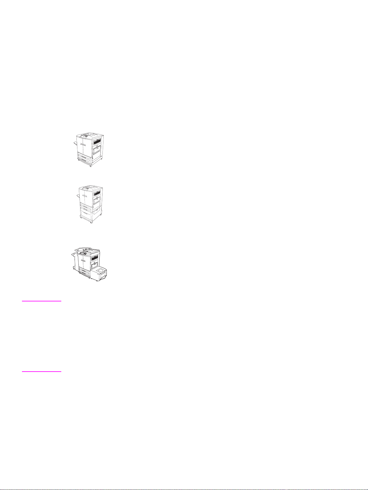
Product features
This manual contains service information for the HP color LaserJet 9500 Series printer and the print
engine portion of the HP color LaserJet 9500mfp. For MFP models, you also need the HP Scanner/
ADF Service Manual for the HP LaserJet 9000mfp/9000Lmfp/9040mfp/9050mfp/9500mfp
(PN C8449-90955) and the 2,000-sheet Side Input Tray Service Manual (PN Q1891-90901) for
complete MFP service information.
Throughout this document, the term “printer” is used to refer to both the HP LaserJet 9500 Series
printer models and the HP LaserJet 9500mfp. Make sure to read the headings and text carefully to
understand the context of the term.
HP Color LaserJet 9500n printer (C8546A)
The HP color LaserJet 9500n printer comes standard with a 128-MB RAM DIMM,
wide-format printing capability, tray 1 (a 100-sheet multipurpose tray), tray 2 and
tray 3 (500-sheet trays), and an HP Jetdirect print server.
HP Color LaserJet 9500hdn printer (C8547A)
The HP color LaserJet 9500hdn printer comes standard with a 256-MB RAM
DIMM, a 20-GB EIO hard disk, wide-format printing capability, tray 1 (a 100-sheet
multipurpose tray), tray 2 and tra y 3 (500-sheet trays), tray 4 (a 2,000-sheet
feeder), an HP Jetdirect print server, and a duplexer (for printing on both sides of
media).
HP Color LaserJet 9500mfp (C8549A)
The HP color LaserJet 9500hdn printer comes standard with a 512-MB RAM
DIMM, a 20-GB EIO hard disk, wide-format printing capability, tray 1 (a 100-sheet
multipurpose tray), tray 2 and tray 3 (500-sheet trays), tray 4 (a side 2,000-sheet
feeder), one of five finishing devices, an HP Jetdirect print server, and a duplexer
(for printing on both sides of media).
Note This manual is used to service the entire HP color LaserJet 9500 Series printer and to service the HP
color LaserJet 9500mfp print engine only . T o service the ADF/scanner portion of the HP color LaserJet
9500mfp, see your HP Scanner/ADF Service Manual for the HP LaserJet 9000mfp/9000Lmfp/
9040mfp/9050mfp/9500mfp (PN C8549-90955). To service the 2,000-sheet side-input tray, see your
2,000-sheet Side-input Tray Service Manual (PN Q1891-90901).
A complete service manual bundle is available by ordering the Service Bundle for
HP Color LaserJet 9500/9500mfp (PN C8549-99001). The service bundle includes the manuals listed
above, this print engine manual, and the Paper Handling Accessories Service Addendum
(PN C85693-90002).
22 Chapter 1 Product information ENWW
Page 25

Features of the HP color LaserJet 9500 series printer
Table 1. Features of the HP color LaserJet 9500 series printer
Speed
Resolution
Consumables
Language
and fonts
Enhanced memory
and memory expansion
Functions
z Up to 24 pages per minute (ppm) for letter- or A4-size media
z Half-speed for glossy or heavy media
z First page out in less than 17 seconds
z Duplexes up to 24 sides per minute for letter- or A4-size media
z 600-by-600 dots per inch (dpi) with Resolutio n Enhanc ement technol og y
(REt)
z HP ImageRet 4800
z Up to 256 levels of gray
z Four no-pull-tab print cartridges
z Four image drums
z PostScript
z HP printer command language (PCL) 6 driver
z HP PCL 5c driver for compatibility with previous products
z Printer job language (PJL)
z Printer management language
z 80 scalable TrueType typefaces
z Direct .pdf printing
z Memory Enhancement technology (MEt ) automat ically compre sses data
®
(PS) Level 3 emulation with 35 built-in PS language fonts
to use RAM more efficiently
z 128 MB of RAM, expandable to 384 MB by using industry-standard 168-
pin DIMM
z Tray 1 supports up to 100 sheets or 10 envelopes for automatic and
manual f eeding of p aper env elope s, label s, tran sparenci es, custom -sized
media (98 by 191 mm [3.8 by 7.5 in] to 312 b y 470mm [12.3 by 18.5 in]),
and heavy paper
z Tray 2 and tray 3 support up to 500 sheets of media
z Tray 4 supports letter, legal, B4, A4, 11-by-17 inch, A3, executive, B5,
and custom (182 by 210mm [7.2 by 8.3 in] to 297 by 431.8mm [11.7 by
17 in]) print media
z Two-sided printing (duplex printing) available
z Wide-format printing
z Glossy printing and document finishing options (hdn model only)
Expandability
z HP color LaserJet 9500 duplexer (standard in the 9500hdn model)
z 3,000-sheet stapler/stacker (for the 9500hdn model only)
z 3,000-sheet stacker (for the 9500hdn model only)
z Multifunction finisher (for the 9500hdn model only)
z Enhanced input/output (EIO) cards
z DIMM slots for adding memory and fonts
z Accepts a 10-GB hard disk for RIP Once capability, job retention
features, and font storage (the hard disk is standard on the 9500hdn
model)
Wireless printing
z Supports wireless printing with the installation of a Fast InfraRed
Connect pod (IrDA compliant)
z Wireless EIO card
Interface connecti on
Networking
Maximum monthly duty cycle
z Bidirectional ECP type-C parallel port (IEEE-1284 compliant)
z Three EIO slots for installation of a hard-disk accessory or print server
z Foreign interface connector
z HP Jet-Link connector
z HP 615N Jetdirect print server
z 200,000 images per month
ENWW Chapter 1 Product information 23
Page 26

Features of the HP Color LaserJet 9500mfp
The HP color LaserJet 9500 Series printer and the HP color LaserJet 9500mfp share most of the
same features. The following list specifies which features are different from those on the printer or
unique to the MFP:
z The MFP includes no top output tray and therefore has no paper path components to top output
tray
z The MFP control panel has different features. See the HP Scanner/ADF Service Manual for the
HP LaserJet 9000mfp/9000Lmf p/90 40m fp/9 050m fp/9 500 mfp for information about the control
panel configuration.
z The 2,000-sheet feeder tray 4 is a side delivery feeder.
z A finishing device is required on the MFP.
z The MFP formatter differs from the printer formatter.
24 Chapter 1 Product information ENWW
Page 27
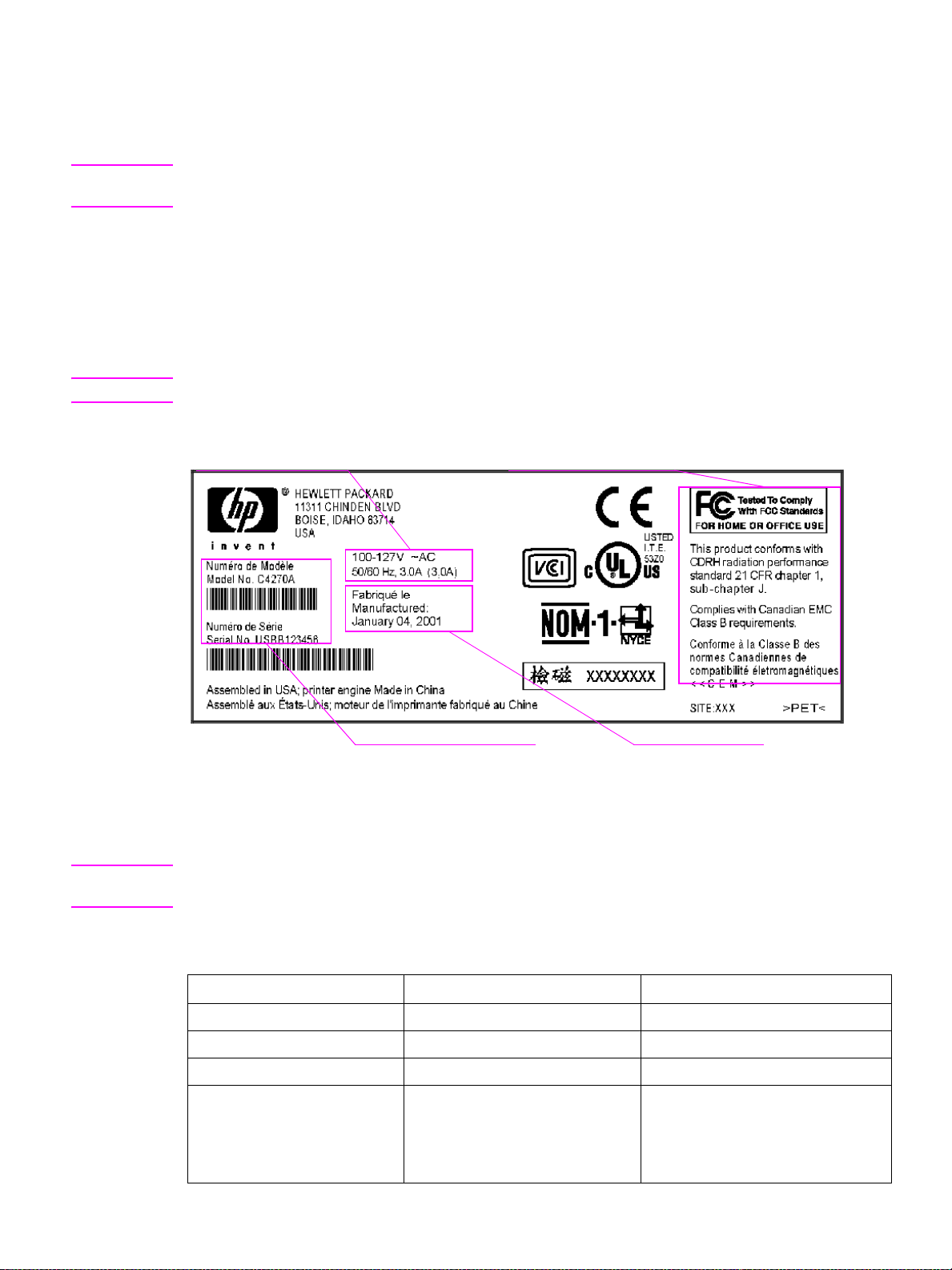
Product specifications for the printer
Identification
Note See the HP Scanner/ADF Service Manual for the HP LaserJet 9000mfp/9000Lmfp/9040mfp/9050mfp/
9500mfp (PN C8549-90955) for information that is specific to the MFP version.
For the HP color LaserJet 9500 Series printer, a user-accessible label is located inside the right door
of the print engine. The model number is alphanumeric, such as C8547A.
The serial number contains information about the country/region of origin and the revision level,
production code, and production number of the printer. An example of a serial number is
USBB123456.
The identification label als o con tai ns elec trical information and regulatory informatio n (s ee figu re 1).
Note The electrical information and regulatory information vary by country/region.
Electrical information Regulatory information
Model and serial number
Figure 1. Sample identification label
Manufacture date
Specifications
Note See the HP Scanner/ADF Service Manual for the HP LaserJet 9000mfp/9000Lmfp/9040mfp/9050mfp/
9500mfp (PN C8549-90955) for information that is specific to the MFP version.
Table 2. Out-of-box specifications
Specification HP color LaserJet 9500n HP color LaserJet 9500hdn
Height 887 mm (34.9 inches) 1,212 mm (47.8 inches)
Width 682 mm (26.9 inches) 682 mm (26.9 inches)
Depth 767 mm (30.2 inches) 767 mm (30.2 inches)
Weight without print cartridges
and image drums
Weight with print cartridges and
image drums in packag ing
100 kg (221 lb)
174 kg (383 lb)
130 kg (287 lb)
198 kg (436 lb)
ENWW Chapter 1 Product information 25
Page 28

Table 3. Packaged specifications
Specification HP color LaserJet 9500n HP color LaserJet 9500hdn
Height 1,313 mm (51.7 inches) 1,488 mm (58.6 inches)
Width 1,200 mm (47.2 inches) 1,200 mm (47.2 inches)
Depth 1,022 mm (40.2 inches) 1,022 mm (40.2 inches)
Table 4. Power requirements and circuit capacity
110-volt models 220-volt models
Power requirements 100 to 127 V (+/- 10%)
50 to 60 Hz (+/- 2 Hz)
Minimum recommended
circuit capacity
15.0 Amps (dedicated circuit) 10.0 Amps (dedicated circuit)
220 to 240 V (+/- 10%)
50 to 60 Hz (+/- 2 Hz)
WARNING! Power requirements are based on the country/region where the printer is sold. Do not convert operating
voltages. This can damage the printer and void the product warranty.
Table 5. Power consumption
Printer state HP color LaserJet 9500n HP color LaserJet 9500hdn
Printing (24 ppm) 722 W 741 W
Standby (Ready) 171 W 173 W
Low Po w erSave (E
High PowerSave (Blue Angel) 32 W 32 W
Off <2 W <2 W
NERGY STAR®) 69 W 69 W
Environmental specific ations
The environmental specifications must be maintained to ensure the proper operation of the printer.
Consider the following points before installing the printer:
z Install the printer in a well-ventilated, dust-free area.
z Install the printer on a level, flat surface that can support its size and weight. Do not install on
carpet or on other soft surfaces. Make sure that all four printer feet are level.
z Install the printer where temperature and humidity are stable, with no abrupt changes (away from
water sources, humidifiers, air conditioners, refrigerators, or other major appliances).
z Install the printer away from direct sunlight, areas that experience vibration, open flames,
ammonia fumes, ultrasonic heaters, and devices that emit a magnetic field. If the printer is
placed near a window, make sure that the window has a curtain or blind to block direct sunlight.
z Maintain enough space around the printer for proper access and ventilation.
26 Chapter 1 Product information ENWW
Page 29

Table 6. Environmental specifications
Allowable condition Recommended condition
Operating temperature 10° to 30° Celsius (C)
(50° to 86° Fahrenheit [F])
Relative humidity 10 to 80 percent 20 to 50 percent
Storage temperature 15° to 30°C (59° to 86°F) 20° to 26°C (68° to 79°F)
Storage humidity 5 percent to 95 percent 5 percent to 95 percent
Table 7. Noise level specifications
Acoustics Printing (24 ppm) PowerSave
Sound power level L
Sound pressure level, L
pAm
(Bystander position)
= 67 dB(A) essentially inaudible
WAd
L
= 50 dB(A) essentially inaudible
pAm
Note Testing per International Standards Organization (ISO) 9296.
20° to 26°C (68° to 79°F)
ENWW Chapter 1 Product information 27
Page 30
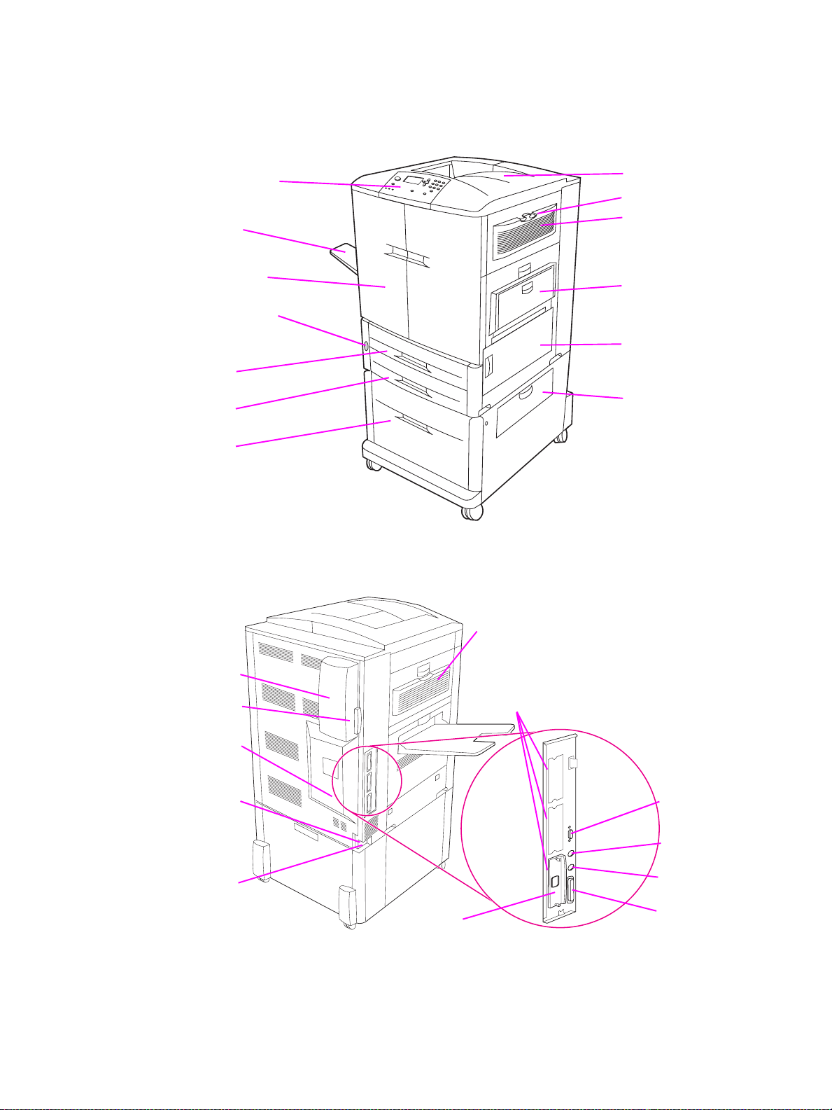
Product overviews
External assembly locations
Control panel
Left bin
Front doors
Power switch
Tray 2
Tray 3
Tray 4
Figure 2. Front and right side assembly locations (HP LJ 9500 Series printer)
Top bin
Ozone filter
Fan cover
Tray 1
Right side
access door
Tray 4
feeder access
Left side
access door
Fan cover
Air filter
Engine-test
button
Power-cord
connector
Accessory
power
connector
HP Jetdirect print
server RJ-45 connector
Figure 3. Back and left side assembly locations (HP LJ 9500 Series printer)
Three EIO slots
HP Jet-Link
connector
HP Fast InfraRed
(FIR) connector
Foreign interface
harness (FIH)
Parallel cable
connector
28 Chapter 1 Product information ENWW
Page 31

Accessories
3,000-sheet stapler/stacker (C8085A)
or 3,000-sheet stacker (C8084A)
Duplexer (C9674A)
Figure 4. Accessories for the HP LJ 9500 Series printer
Multifunction finisher (C8088A)
HP Fast InfraRed
receiver (FIR) (C4103A)
ENWW Chapter 1 Product information 29
Page 32

Control panel
Power switch
Stacker, stapler/stacker,
or multifunction finisher
ADF feeder
ADF/scanner
2,000-sheet
side feeder
Figure 5. Front and right side view (HP LJ 9500mfp)
30 Chapter 1 Product information ENWW
Page 33

Air filter
Power-cord connector
Hard disk
Disk-drive security lock
RJ11 connector
HP Jet-Link
connector
Parallel port
FIH connector
EIO connector
USB connector
Figure 6. Back and left side view (HP LJ 9500mfp)
ENWW Chapter 1 Product information 31
Page 34

Space requirements
Note See the HP Scanner/ADF Service Manual for the HP LaserJet 9000mfp/9000Lmfp/9040mfp/9050mfp/
9500mfp (PN C8549-90955) for information that is specific to the MFP version.
Printer with packaging
The shipping box that contains the HP color LaserJet 9500 series printer is 1,200 mm (47.2 inches)
wide and 1,022 mm (40.2 inches) deep. The shipping box that contains the HP color LaserJet 9500n
is 1,313 mm (51.7 inches) high, and the shipping box that contains the HP color LaserJet 9500hdn is
1,488 mm (58.6 inches) high. The in-box weight of the HP color LaserJet 9500n is 174 kg (383 lb),
and the in-box weight of the HP color LaserJet 9500hdn is 198 kg (436 lb).The customer must locate
a door or receiving area that is large enough to accept delivery of the shipping box.
Note Before removing the printer from the box, make sure that adequate space is available to unpack the
printer and to roll the product off of the shipping pallet. At least 10 feet of clearance around the box is
required to remove all of the shipping materials.
32 Chapter 1 Product information ENWW
Page 35

Physical dimensions of the printer models and the MFP
358 mm
(14.1 inches)
682 mm (26.9 inches)
465 mm
(18.3 inches)
767 mm (30.2 inches)
(17.9 inches)
455 mm
887 mm (34.9 inches)
Figure 7. HP color LaserJet 9500n printer dimensions (top and front views)
ENWW Chapter 1 Product information 33
Page 36

358 mm
(14.1 inches)
682 mm (26.9 inches)
465 mm
(18.3 inches)
767 mm (30.2 inches)
455 mm
(17.9 inches)
1,212 mm (47.8 inches)
Figure 8. HP color LaserJet 9500hdn printer dimensions (top and front views)
34 Chapter 1 Product information ENWW
Page 37

543 mm
(21.4 in)
603 mm
(23.7 in)
1,080 mm (42.5 in)
647 mm
(25.5 in)
635 mm
(25 in)
2,660 mm
(104.7 in)
415 mm
(16.3 in)
420 mm
(16.5 in)
575 mm
(22.6 in)
1,219 mm (48 inches)
904 mm (35.6 inches)
Figure 9. HP color LaserJet 9500mfp dimensions
475 mm
(18.7 inches)
1,651 mm (65 inches)
ENWW Chapter 1 Product information 35
Page 38

Printer setup
Note See the HP Scanner/ADF Service Manual for the HP LaserJet 9000mfp/9000Lmfp/9040mfp/9050mfp/
9500mfp (PN C8549-90955) for information about the MFP.
The initial printer setup includes the following steps:
z Remove the printer from the box.
z Set up and install the printer. See the HP color LaserJet 9500 User Reference Guide at
http://www.hp.com/support/lj9500.
z Set up and install the finishing device (for the 9500hdn only). See the install guide that came with
the finishing device.
The shipping box contains the following items:
z HP color LaserJet 9500 series printer
z One power cord
z Control panel overlay
z Consumables box
• Four print cartridges
• Four image drums
• One image cleaning blade
• One toner collection bottle
z Printer software on CD-ROM (includes the HP color LaserJ et 9500 Use r Reference Guide)
z Start guide
Note The finishing device is delivered in a separate box (optional for the 9500hdn model only).
The HP color LaserJet 9500hdn is delivered with the duplexer, hard disk, network card, and tray 4
installed.
36 Chapter 1 Product information ENWW
Page 39

Media specifications
Before purchasing large quantities of print media, make sure that it meets the requirements specified
in this service manual and in the HP color LaserJet 9500 User Ref erence Guide. Alwa ys test the print
media before buying large quantities.
Hewlett-Packard neither warrants nor recommends the use of a particular brand of paper or print
media other than HP media. Media properties are subject to manufacturing changes, and HP has no
control over such changes. Although testing the media helps to characterize the performance and
the manufacturer’s process quality, the customer assumes all responsibility for the quality and
performance of media.
CAUTION Using print media that does not meet HP specifications might cause problems for the product, requiring
repair. Such repair is not covered by the Hewlett-Packard warranty or service agreements.
The HP color LaserJet 9500 series printers accept a variety of media, such as cut-sheet paper
(including up to 100 percent recycled fiber-content paper), envelopes, labels, transparencies, and
custom-size paper. Properties such as weight, composition, grain, and moisture content are
important factors affecting printer performance and output quality. Media that does not meet the
guidelines outlined in this manual and in the print media guide can cause the following problems:
z poor print quality
z increased jams
z premature wear on the printer, requiring repair
Guidelines for selecting media
This product accepts a variety of media, such as cut-sheet paper (including recycled paper),
envelopes, labels, transparencies, and custom-size paper. Properties such as weight, grain, and
moisture content are important factors that affect product performance and print quality.
Selecting media by type and size at the control panel and in the printer driver results in significantly
better print quality for heavy paper and glossy paper. Using the wrong setting can result in
unsatisfactory print quality. Always print by type for special print media such as labels or
transparencies. Always print by size for envelopes.
The product can use a variety of paper and other print media in accordance with the guidelines in this
manual. Paper that does not meet these guidelines can cause the following problems:
z poor print quality
z media jams and multiple-sheet feeds
z premature wear on the printer, requiring repair
Note Some print media might meet all of the guidelines in this manual and still not produce satisfactory
results. This might be the result of improper handling, unacceptable temperature and humidity levels,
or other variables over which HP has no control.
If you are unsure what type of paper you are loading (such as bond or recycled), check the label on
the package of paper.
z See “Basis weight field test” on page 46 for information about measuring basis weight.
z See “Caliper field test” on page 48 for information about measuring caliper.
z See “Paper finish field test” on page 48 for information about smoothness.
Hint Do not purchase more media than can be easily used in a short time (about 3 months). Media that is
stored for long periods experiences heat and moisture extremes that can be damaging. Planning is
important to prevent damage to a large supply of media.
ENWW Chapter 1 Product information 37
Page 40

Supported media and capacity for input and output
Note The leading edge is listed first in the dimension measurements.
Table 8. Supported standard media sizes
Printing task Tray 1 Tray 2 and tray 3 Tray 4
Simplex, and manual and
auto duplex
z letter, legal, executive,
ISO A3, ISO A4, ISO
A5, 11 by 17, JIS B5,
JIS B4, JPostD, 8K, 16K
z letter, legal,
executive, ISO A3,
ISO A4, ISO A5, JIS
B4, JIS B5, 11 by 17
z letter, legal,
executive, ISO A3,
ISO A4, 11 by 17,
JIS B4, JIS B5
Table 9. Maximum custom sizes
Printing task Tray 1 Tray 2 and tray 3 Tray 4
Simplex, and manual and
auto duplex
z 306 by 470 mm (12.05
by 18.5 inches)
z 297 by 432 mm
(11.7 by 17 inches)
z 297 by 432 mm
(11.7 by 17 inches)
Table 10. Minimum custom sizes
Printing task Tray 1 Tray 2 and tray 3 Tray 4
Simplex and manual duplex z 98 by 170 mm (3.9 by
6.7 inches)
Auto duplex
z 148 by 210 mm (5.8 by
8.3 inches)
z 148 by 210 mm (5.8
by 8.3 inches)
z 148 by 210 mm (5.8
by 8.3 inches)
z 182 by 210 mm (7.2
by 8.3 inches)
z 182 by 210 mm (7.2
by 8.3 inches)
Table 11. Supported media weights
Printing task Tray 1 Tray 2 and tray 3 Tray 4
Simplex and manual duplex z 64 to 220 g/m2
(17- to 58-lb bond)
Auto duplex
z 64 to 200 g/m
(17- to 53-lb bond)
z 64 to 200 g/m
(17- to 53-lb bond)
2
z 64 to 200 g/m
(17- to 53-lb bond)
2
z 64 to 200 g/m
(17- to 53-lb bond)
2
z 64 to 200 g/m
(17- to 53-lb bond)
2
2
Table 12. Input tray capacities
Type of media Tray 1 Tray 2 and tray 3 Tray 4
Cut sheets z up to 100 sheets
(10 mm total height,
5 mm total height for
media that is 200 g/m
[53-lb bond] or heavier)
Envelopes
z up to 10 envelopes
(10 mm total height)
Up to 500 sheets Up to 2,000 sheets
2
Not supported Not supported
Table 13. Output bin capacities
Bin
75 g/m2 (20-lb bond)
Top bin (face down) z up to 500 sheets Up to 50 sheets
Left bin (face up)
z up to 100 sheets Up to 10 sheets
Transparencies
CAUTION Do not use paper that is heavier than 200 g/m2 (53-lb bond) for duplex printing. Damage to the product
and jams might result.
38 Chapter 1 Product information ENWW
Page 41

Recommended media
The media types that are listed in the following table meet these criteria:
z They have been tested in this product.
z They have proven to be of good quality.
z They work well with the product’s settings.
Ordering recommended media
The product numbers for media are listed in parentheses after the media sizes. Use these product
numbers when ordering media.
All of the HP-brand media is available at www.hpshopping.com
or from your local office supplies
retailer.
The product supports the StoraEnso paper that is listed in the table. It is available through your local
office products supplier.
Note Set the type at the control panel when you load the trays, and in the printer driver when you print
your print job.
Table 14. Recommended media
Recommended media Type Characteristics
HP High Gloss Laser Paper
letter (Q2419A)
11 by 17 (tabloid) (Q2420A)
A4 (Q2421A)
A3 (Q2422A)
HP Premium Cover Paper
letter (Q2413A)
A4 (Q2414A)
HP Color Laser Paper
letter (HPL245R)
11 by 17 (tabloid) (HPL2417)
HP Color Laser Paper
105 g/m
letter (HPL285R)
11 by 17 (tabloid) (HPL2817)
HP Soft Gloss Laser Paper
letter (C4179A)
A4 (C4179B)
Note
HP Soft Gloss Laser Paper is designed
specifically for use with the HP color
LaserJet 9500 series printers.
2
(28-lb bond)
HP HEAVY
GLOSSY
CARDSTOCK
>164 g/m2
PLAIN 90 g/m
PLAIN 105 g/m
HP HEAVY
GLOSSY
120 g/m2 (32-lb bond), 200 sheets,
high-gloss finish coating on both
sides, 95 bright
Use for: brochures, catalogs , business
plans, photographs, and images
200 g/m
super-smooth matte finish on both
sides, 96 bright
Use for: postcards and document
covers
smooth matte finish on both sides, 96
bright
Use for: newsletters and color
documents
smooth matte finish on both sides, 96
bright
Use for: newsletters and color
documents
120 g/m
satin finish coating on both sides, 96
bright
Use for: flyers, handou ts, sales briefs,
proposals, and color image s
2
(75-lb cover), 100 sheets,
2
(24-lb bond), 500 sheets,
2
(28-lb bond), 500 sheets,
2
(32-lb bond), 200 sheets,
ENWW Chapter 1 Product information 39
Page 42

Table 14. Recommended media (continued)
Recommended media Type Characteristics
HP Soft Gloss LaserPaper
105 g/m
2
(28-lb bond)
letter (Q2415A)
11 by 17 (tabloid) (Q2416A)
A4 (Q2417A)
A3 (Q2418A)
HP Premium Choice LaserJet Paper
letter (HPU1132)
11 by 17 (tabloid) (HPU1732)
A4 (CHP410)
A4 (Asia) (Q2397A)
A3 (Asia) (Q2396A)
HP Premium Choice LaserJet Paper
160 g/m
2
(42-lb bond)
A4 (Europe) (CHP413)
A3 (Europe) (CHP421)
HP LaserJet Paper
letter (HPJ1124)
3-hole prepunched (HPJ113H)
legal (HPJ1424)
11 by 17 (tabloid) (HPJ1724)
A4 (Europe) (CHP310)
GLOSSY
75-105 g/m
105 g/m2 (28-lb bond), 500 sheets,
2
satin finish coating on both sides, 96
bright
Use for: flyers, handou ts, sales briefs,
proposals, and color image s
HEAVY
106-163 g/m
120 g/m2 (32-lb bond), 500 sheets
2
(250 sheets for 11 b y 17 ), ma tte fi nis h
on both sides, 98 bright
Use for: proposals and charts
HEAVY
106-163 g/m
160 g/m2 (42-lb bond), 250 sheets,
2
matte finish on both sides 98 bright
Use for: proposals and charts
PLAIN 90 g/m2 (24-lb bond), 500 sheets,
matte finish on both sides, 96 bright
Use for: reports, user manuals,
letterhead, and correspondence
HP Office Recycled Paper
letter (HPE1120)
3-hole prepunched (HPE113H)
legal (HPE1420)
HP Tough Paper
letter (Q1298A)
A4 (Q1298B)
HP Color LaserJet Transparencies
letter (C2934A)
A4 (C2936A)
StoraEnso Futura Laser Cover
11 by 17 (01109)
PLAIN 75 g/m2 (20-lb bond), 500 sh eets,
matte finish on b oth side s, cont ains 30
percent post-consumer content
(satisfies U.S. Executive Order
13101), 87 bright
Use for: training manuals and general
office printing
TOUGH PAPER 5 mil thick (approximately 44-lb bond
equivalent), 50 sheets, satin finish
coating on both sides, waterproof,
tearproof
Use for: signs, maps, rest aur a nt
menus, waterproof documents, and
tearproof documents
TRANSPARENCY 5 il thick, 50 sheets, premium coated
both sides
Use for: transparencies
2
NON HP HEAVY
GLOSSY
163 g/m
coated, premium white
(60-lb cover), 250 sheets,
Use for: document cov e r
40 Chapter 1 Product information ENWW
Page 43

Table 15. Media weight, finish, and type
Weight Finish Type
Less than 75 g/m² (20-lb bond) any LIGHT<75 g/m
75 g/m ² (20-lb bond) to 105 g/m² (28-lb bond) matte PLAIN
75 g/m ² (20-lb bond) to 105 g/m² (28-lb bond) glossy GLOSSY 75-105 g/m
106 g/m² (29-lb bond) to 163 g/m² (43-lb bond) matte HEAVY 106-163 g/m
106 g/m² (29-lb bond) to 163 g/m² (43-lb bond) glossy HP HEAVY GLOSSY (if usi ng
HP-brand media)
NON HP HEAVY GLOSSY (if
using non-HP-brand
media)
164 g/m² (44-lb bond) and heavier any CARDSTOCK>164 g/m
Special media specifications
Envelope specifications
Successful printing on envelopes depends upon the quality of the envelopes. Envelope fold lines can
vary considerably, not only between manufacturers, but also within a box from the same
manufacturer. When selecting envelopes, consider the following components:
z Construction: Prior to printing, envelopes should lie flat with less than 6 mm (0.25 inch) curl,
and have well-constructed seams.
z Condition: Envelopes should not be wrinkled, nicked, or otherwise damaged.
z Temperature: Envelopes should be compatible with the heat and pressure produced by the
printer.
Figure 10. Sample seams
ENWW Chapter 1 Product information 41
Page 44
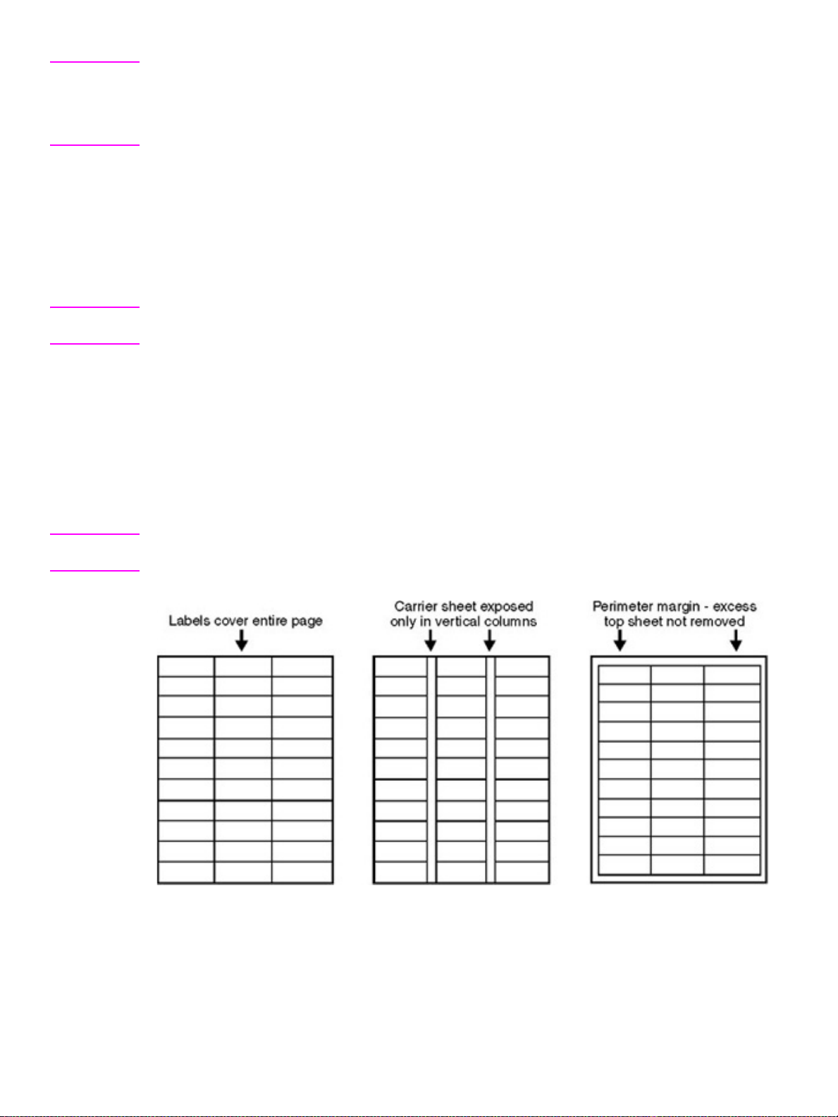
Note Print on envelopes from tray 1 only . Send envelopes straight through the printer, entering at tray 1 and
exiting from the face-up bin.
For the best print quality, position margins no closer than 15 mm (0.6 inch) from the edges of the
envelope. A void printing over the area where the envelope seams meet.
Envelopes with adhesive strips or multiple flaps
Envelopes with a peel-off adhesive strip, or with more than one flap that folds over to seal, must use
adhesives that are compatible with the heat and pressure of the printer. The extra flaps might cause
wrinkling, creasing, or jams.
Label specifications
CAUTION T o a void damaging the printer, use only labels that are recommended for laser printers. Never print on
the same sheet of labels more than once and never print on a partial sheet of labels.
When selecting labels, consider the quality of each component:
z Adhesives: The adhesive material should be stable at 200° C (392° F), which is the printer
fusing temperature.
z Arrangement: Do not use labels that have exposed backing between them. Labels can peel off
sheets with spaces between the labels, causing jams.
z Curl: Prior to printing, labels must lie flat with no more than 13 mm (0.5 inch) of curl in any
direction.
z Condition: Do not use labels that have wrinkles, bubbles, or other indications of separation.
Note Use only tray 1 to print on labels. Send labels straight through the printer, entering at tray 1 and exiting
from the face-up bin.
Figure 11. Adhesive labels
42 Chapter 1 Product information ENWW
Page 45

Card stock construction
When selecting card stock, consider the quality of each component:
z Smoothness: 135- to 220-g/m
2
(36- to 58-lb bond) card stock should have a smoothness rating
of 100 to 180 Sheffield.
z Curl: Card stock should lie flat with less than 5 mm (0.2 inch) of curl.
z Condition: Make sure that the card stock is not wrinkled, nicked, or otherwise damaged.
z Size: See “Supported media and capacity for input and output” on page 38.
z Weight: Card stock of 200 g/m
200 g/m
2
(53 lb) must be printed from tray 1.
2
(53 lb) or less can be loaded in any tray. Card stock heavier than
Note When printing on card stock, make sure to set the CARDSTOCK type at the control panel when you load
the tray, and in the printer driver when you print your print job.
Transparency specifications
To avoid damaging the printer, use only transparencies that are recommended for use in color laser
printers.
z Construction: Prior to printing, transparencies should lie flat with less than 10 mm (0.39 inch)
curl.
z Condition: Transparencies should not be wrinkled, nicked, or otherwise damaged.
z Temperature: Transparencies should be stable at 190° C (374° F), which is the printer fusing
temperature.
z Size: 5 mm thick (0.005 inch)
Note If problems occur while printing on transparencies, use tray 1. Send transparencies straight through
the printer, entering at tray 1 and exiting from the face-up bin.
CAUTION Transparencies used in the printer must be able to withstand 190° C (374° F), the printer fusing
temperature.
Preprinted forms and special letterhead
Many preprinted forms and special letterhead papers perform well in HP LaserJet printers. However,
these papers undergo processes that alter their original characteristics, and care must be taken to
ensure they conform to HP specifications. All special papers should be wrapped in moisture-proof
wrapping when purchased from the paper converter or printing house.
Forms and letterhead must be printed with inks that conform to the following specifications:
z Only use ink that is heat-resistant, and that will not melt, scorch, or release hazardous emissions
when subjected to 200
z Inks must have resistance to silicon oils, and must not be affected by resin components in toner.
z Inks must not be flammable.
z Inks must not “offset” (transfer from the printed paper onto the printer, contaminating internal
printer components). The principle cause of offset is ink that is not fully dried or that cannot
withstand the printer fusing temperature.
Note Do not use forms or letterhead that was produced by using low-temperature inks (the kind used with
thermography).
° C (392° F) for 0.1 second.
ENWW Chapter 1 Product information 43
Page 46

Embossed media
Embossed media is not recommended for use in HP LaserJet products. Media is embossed by
stamping an image into the media by compressing the media fibers together at approximately 200
(392
° F), and sometimes by applying a thin metal foil to the surface. The product fusing process can
loosen the foil; loose foil can interfere with the mechanical and electronic operation of the product.
Embossed paper, with or without foil, can also cause multifeed jams. Multiple embossed print media
sheets tend to stick to one another.
Glossy media
Keep these considerations in mind when selecting or printing on glossy media:
z Print quality can vary with the media used. For best results, use HP-brand glossy media.
z When using media that has only one glossy side, make sure to orient the media so that the
printer prints on the glossy side.
Note When printing on glossy media that is between 75 g/m2 (20-lb bond) and 105 g/m2 (28-lb bond) in
weight, make sure to set the GLOSSY type at the control panel when you load the tray , and in the printer
driver when you print your print job.
° C
When printing on HP-brand glossy media that is between 106 g/m
2
(29-lb bond) and 163 g/m2 (43-lb
bond) in weight, make sure to set the HP HEAVY GLOSSY type at the control panel when you load the
tray, and in the printer driver when you print your print job.
When printing on non HP-brand glossy media that is between 106 g/m
2
(29-lb bond) and 163 g/m
2
(43-lb bond) in weight, make sure to set the NON HP HEAVY GLOSSY type at the control panel when you
load the tray, and in the printer driver when you print your print job.
Media with cutouts or perforations
Avoid media with cutouts or perforations for these reasons:
z Cut fibers absorb more moisture and can increase waviness and media curl. This decreases the
print quality near the cutout or perforated area.
z Cutting knives leave a sharp edge on the cutout or perforation. If the sharp edge is facing the
print cartridge drum during printing, it can scratch the drum surface.
z If printing occurs over a cutout hole, the transfer roller is contaminated with unused toner,
creating light streaks on the paper.
Chemically treated media
Coatings such as lacquers, polymers, laminations, or other chemicals protect the paper, but can
cause problems in the fuser and transfer areas of HP LaserJet products. The surface resistivity and
moisture content can be greatly altered, resulting in print-quality problems. Hard surface coatings
increase wear on the rollers and media guides. All chemically treated media must meet
Hewlett-Packard specifications for fusing compatibility.
Synthetic media
Synthetic media (those manufactured from man-made fibers) do not perform as well as bond media
in any printer or MFP, especially HP LaserJet products. All synthetic media must meet HewlettPackard specifications, especially for caliper and fusing compatibility.
44 Chapter 1 Product information ENWW
Page 47

Other special media
z Non-standard sizes. Check minimum and maximum supported sizes on page 38.
z Carbonless media. Carbonless media (NCR) is not supported by HP LaserJet products.
z Recycled media. Choose recycled media that meets Hewlett-Packard specifications. Note that
recycled media might not be as bright as indicated in the specifications. Hewlett-Packard
recommends that recycled media contain no more than 5 percent groundwood. See “Testing
media specifications” on page 45.
Storing print media
Ideally, the printing and media storage environment should be at or near room temperature, and
should not be too dry or too humid. Remember that paper is hygroscopic; it absorbs and loses
moisture rapidly.
Heat works with humidity to damage paper. Heat causes the moisture in paper to evaporate, while
cold causes it to condense on the sheets. Heating systems and air conditioners remove most of the
humidity from a room. As a paper package is opened and used, it loses moisture, causing streaks
and smudging. Humid weather or water coolers can cause the humidity in a room to increase. As a
package of paper is opened and used, it absorbs any excess moisture, causing light print and
dropouts. Also, as paper loses and gains moisture, it can distort. This can cause jams.
Therefore, paper storage and handling are as important as the paper-making process itself. Paper
storage environmental conditions directly affect the feed operation.
Users should not purchase more paper than can easily be used in a short time (about three months).
Paper stored for long periods might experience heat and moisture extremes, which can cause
damage. Planning is important to prevent damage to a large supply of paper.
Unopened paper in sealed packages can remain stable for several months before use. Opened
packages of paper have more potential for environmental damage, especially if they are not wrapped
with a moisture-proof barrier.
The paper storage environment should be correctly maintained to ensure optimum printer
performance. The required condition is 20
° to 24° C (68° to 75° F), with a relative humidity of 45
percent to 55 percent. The following guidelines should be helpful when evaluating the paper’s
storage environment:
z Paper should be stored at or near room temperature.
z The air should not be too dry or too humid (because of the hygroscopic properties of paper).
z The best way to store an opened package of paper is to rewrap it tightly in its moisture-proof
wrapping. If the printer environment is subject to extremes, unwrap only the amount of paper to
be used during the day's operation to prevent unwanted moisture changes.
Envelope storage
Proper storage of envelopes contributes to good print quality. Env elopes should be stored flat. If air is
trapped in an envelope, and creates an air bubble, then the envelope might wrinkle during printing.
Testing media specifications
The following tests describe ways to evaluate media with respect to the specifications listed in this
manual, and the HP LaserJet Printer Family Print Media Guide. See “Media assessment tools and
suppliers” on page 50 for help obtaining the tools that are needed to perform these tests.
ENWW Chapter 1 Product information 45
Page 48

Basis weight field test
The basis weight should be indicated on the package label. If the label is not available, a simple field
test can determine the basis weight of paper. The basis weight of paper is equal to the weight of
2,000 sheets of paper, or about four full packages. Weigh a full package on a postal scale and then
multiply that weight by four. Or weigh 10 sheets of paper, divide that weight by 10, multiply by 2,000,
and then divide by 16.
Example 10 sheets weigh 1.6 ounces ÷ 10
0.16 ounce x 2,000 = 320 ounces
320 ounces ÷ 16 ounce/lb = 20 lb paper (letter only)
Table 16. Determining basis weight of paper
Amount Formula
Four packages weight = basis weight
One package weight x 4 = basis weight
10 sheets (weight divided by 10) x 2,000 and then divided by 16 = basis weight
Metric sizes
For metric-size paper (A4), use the following method to determine basis weight.
Take 16 sheets of A4 paper and weigh them. One square meter of paper contains approximately 16
A4 size sheets. Compare this weight to the appropriate weight in the paper weight equivalence table.
Paper weight equivalence table
Use this table to determine approximate equivalent points in weight specifications other than U.S.
bond weight. For example, to determine the equivalent of 20 lb U.S. bond-weight paper in U.S. coverweight paper, locate the bond weight (in row 3, second column) and scan across the row to the cover
weight (in the fourth column). The equivalent is 28 lb. Shaded areas indicate a standard weight for
that grade.
Table 17. Paper weight equivalence
U.S. postcard
thickness
(mm)
U.S. bond
weight (lb)
U.S. text/
book
weight (lb)
U.S. cover
weight (lb)
U.S. bristol
weight (lb)
U.S. index
weight (lb)
U.S. tag
weight (lb)
Europe
metric
weight
2
(g/m
17 43 24 29 35 39 64 64
20 50 28 34 42 46 75 75
21 54 30 36 44 49
80 80
22 56 31 38 46 51 81
24 60 33 41 50 55 90 90
27 68 37 45 55 61
100 100
28 70 39 49 58 65 105 105
32 80 44 55 67 74 120 120
Japan
metric
weight
)
(g/m2)
81
34 86 47 58 71 79 128
128
36 90 50 62 75 83 135 135
0.18 39 100 55 67 82 91 148 148
0.19 42 107 58 72 87 97 157
157
0.20 43 110 60 74 90 100 163 163
46 Chapter 1 Product information ENWW
Page 49

Table 17. Paper weight equivalence (continued)
U.S. postcard
thickness
(mm)
U.S. bond
weight (lb)
U.S. text/
book
weight (lb)
U.S. cover
weight (lb)
U.S. bristol
weight (lb)
U.S. index
weight (lb)
U.S. tag
weight (lb)
0.23 47 119 65 80 97 108 176 176
53 134 74 90 110 122 199 199
54 137 75 93 113
58 146
80 98 120 133 216 216
125 203 203
65 165 90 111 135 150 244 244
66 169 92 114 138 154
67 171 94 115
140 155 253 253
70 178 98 120 146 162 264 264
72 183
100 123 150 166 271 271
Note The U.S. postcard measurements are approximate. Use for reference only.
Europe
metric
weight
2
(g/m
Japan
metric
weight
)
(g/m2)
250 250
ENWW Chapter 1 Product information 47
Page 50

Caliper field test
The specified caliper differs according to the type of media used. Caliper can be measured in the
field by using a micrometer.
CAUTION Never use the coarse adjustment end of the micrometer when measuring for caliper. The coarse
adjustment will compress the paper fibers, resulting in an inaccurate reading. For example, if the fibers
are compressed, 6 mm (0.24 inch) paper could measure as little as 3 mm (0.12 inch). Always use the
fine adjustment to measure caliper.
Using the fine adjustment, slide the micrometer along the edge of the paper and measure at one
end. To double-check the accuracy of the reading, always measure again at the opposite end of the
paper.
Paper finish field test
Paper finish, or smoothness, can be accurately measured with a Sheffield meter. If this tool is not
available, a new U.S. dollar bill can be used as a benchmark for comparing paper texture. A dollar bill
has a finish of 350 Sheffields. If paper feels rougher than a dollar bill, it is recommended that users
do not continually use this paper in the printer.
Moisture content field test
Specification: Use paper with 4 percent to 6 percent moisture content.
A package or a sheet of paper can be measured with a moisture meter. In general, only evaluate
customer storage environment when trying to determine if excess moisture or dryness is the cause
of a problem with paper.
Grain field test
Grain direction is usually specified on the package label (written out “long” or “short”). The paper
dimensions listed on the label also indicate grain direction. For example, short-grain letter-size paper
labels are marked “11 by 8.5,” and long-grain paper labels are marked “8.5 by 11."
If grain direction is not included on the package label, it can be determined by a simple wet test. Cut
a small square from the corner of a sheet of paper, wet it, and observe the manner in which it curls.
Envelopes should have a diagonal grain, which gives them the best stability. To determine this, cut a
square section from one corner of an envelope. Wet this section and observe the manner in which it
curls. On diagonal grain envelopes, the two opposite corners will curl toward each other.
Figure 12. Long, short, and diagonal grain curl
48 Chapter 1 Product information ENWW
Page 51

Curl field test
To check for paper curl, place a single sheet of paper on a flat surface and measure curl at the
greatest deflection, holding a ruler perpendicular to the flat surface.
Figure 13. Measuring curl
Cut edge condition field test
The condition of the cut edge can be easily observed with an eye loop. Under magnification, a good
edge will appear even. A poorly cut edge will show fraying, jagged edges, compressed fibers, and
other damage.
Furnish (fiber composition) field test
Use paper made from 100 percent chemical wood pulp and/or cotton fiber. Recycled paper made
with no more than 5 percent groundwood is also acceptable.
Read the package label to determine the fiber composition of the paper. Paper is usually specified as
xerographic bond (suitable for copiers or laser printers) or cotton bond. Cotton bond paper of
25 percent, 50 percent, or 100 percent will be indicated on a watermark. If paper is less than
25 percent cotton bond, the watermark will not indicate a percentage. A wood pulp test kit can also
be used to test fiber composition.
Fusing compatibility field test
Inspect the rollers for colored ink buildup from preprinted logos or letterhead, and for toner buildup or
spots. Inspect printed output for repetitive defects and smearing. If necessary, hav e users contact the
forms vendor to ensure paper fusing compatibility with HP LaserJet printers.
ENWW Chapter 1 Product information 49
Page 52

Media assessment tools and suppliers
Hewlett-Packard neither warrants nor recommends a particular manufacturer, supplier, or tool.
Products are subject to change, and HP has no control over such changes. However, the following
table of tools and their suppliers is provided for convenience.
Table 18. Tools and suppliers
Tool Part Number Supplier Address
Paper moisture meter 2RRDMP Mitchell Instrument
Single-sheet clamp probe 2R43E Mitchell Instrument
Temperature/humidity meter #3T331 Industrial Motor Service
Sheffield tester: precisionaire column TM 58-25-01 TMI Testing Machines Inc.
Sheffield tester: smooth check gauge TM 58-25-02 TMI Testing Machines Inc.
1570DDD Cheroke St.
San Marcos, CA 92069-2433
1570DDD Cheroke St.
San Marcos, CA 92069-2433
2000 Albright
Montgomery, IL 60538
400 Bayvie w Avenue
Amityville, NY 11701
(516) 842-5400
400 Bayvie w Avenue
Amityville, NY 11701
(516) 842-5400
Wood pulp test kit 4280-2 Shape Products
1127 57th Avenue
Oakland, CA 94621
(800) 444-0015
pH test kit 4360-2 Shape Products
1127 57th Avenue
Oakland, CA 94621
(800) 444-0015
Resistivity test tool:
precision current/resistance meter
Resistivity test tool:
surface resistivity probe
278 Monroe Electronics
100 Housel A venue
PO Box 100
Lyndonville, NY 14098
(800) 821-6001
96117-1 Monroe Electronics
100 Housel A venue
PO Box 100
Lyndonville, NY 14098
(800) 821-6001
50 Chapter 1 Product information ENWW
Page 53

2 Service approach
Chapter contents
Service approach . . . . . . . . . . . . . . . . . . . . . . . . . . . . . . . . . . . . . . . . . . . . . . . . . . . . . . . . . . . . .52
Parts and supplies. . . . . . . . . . . . . . . . . . . . . . . . . . . . . . . . . . . . . . . . . . . . . . . . . . . . . . . . . . . . .53
Ordering parts. . . . . . . . . . . . . . . . . . . . . . . . . . . . . . . . . . . . . . . . . . . . . . . . . . . . . . . . . . . . .53
Ordering supplies . . . . . . . . . . . . . . . . . . . . . . . . . . . . . . . . . . . . . . . . . . . . . . . . . . . . . . . . . .53
Exchange program . . . . . . . . . . . . . . . . . . . . . . . . . . . . . . . . . . . . . . . . . . . . . . . . . . . . . . . . .53
Supplies . . . . . . . . . . . . . . . . . . . . . . . . . . . . . . . . . . . . . . . . . . . . . . . . . . . . . . . . . . . . . . . . .53
World Wide Web. . . . . . . . . . . . . . . . . . . . . . . . . . . . . . . . . . . . . . . . . . . . . . . . . . . . . . . . . . .53
HP service parts information compact disc. . . . . . . . . . . . . . . . . . . . . . . . . . . . . . . . . . . . . . . 54
Customer care reseller sales and service support center. . . . . . . . . . . . . . . . . . . . . . . . . . . .54
Ordering related documentation and software . . . . . . . . . . . . . . . . . . . . . . . . . . . . . . . . . . . .55
Warranty . . . . . . . . . . . . . . . . . . . . . . . . . . . . . . . . . . . . . . . . . . . . . . . . . . . . . . . . . . . . . . . . . . . . 56
Limited warranty for print cartridge and image drum life . . . . . . . . . . . . . . . . . . . . . . . . . . . . . . . .56
Transfer unit and fuser warranty . . . . . . . . . . . . . . . . . . . . . . . . . . . . . . . . . . . . . . . . . . . . . . . . . .56
HP maintenance agreements . . . . . . . . . . . . . . . . . . . . . . . . . . . . . . . . . . . . . . . . . . . . . . . . . . . .56
Onsite service agreements. . . . . . . . . . . . . . . . . . . . . . . . . . . . . . . . . . . . . . . . . . . . . . . . . . .57
ENWW Chapter 2 Service approach 51
Page 54

Service approach
Note This manual is used to service the entire HP color LaserJet 9500 Series printer and to service the HP
color LaserJet 9500mfp print engine only . T o service the ADF/scanner portion of the HP color LaserJet
9500mfp, see your HP Scanner/ADF Service Manual for the HP LaserJet 9000mfp/9000Lmfp/
9040mfp/9050mfp/9500mfp (PN C8549-90955). To service the 2,000-sheet side-input tray, see your
2,000-sheet Side-Input Tray Service Manual (PN Q1891-90901).
A complete service manual bundle is available by ordering the Service Bundle for
HP Color LaserJet 9500/9500mfp (PN C8549-99001). The service bundle includes the manuals listed
above, this print engine manual, and the Paper Handling Accessories Service Addendum
(PN C85693-90002).
Throughout this document, the term “printer” is used to refer to both the HP LaserJet 9500 Series
printer models and the HP LaserJet 9500mfp. Make sure to read the headings and text carefully to
understand the context of the term.
The HP color LaserJet 9500 is designed to be diagnosed over the phone, and repaired in the field.
Repair of the printer normally begins with a three-step process:
1 Isolate the problem to the major system (the host computer, the network or server, or the printer).
2 Isolate the problem to the print engi ne, the input device, the ADF/scan engine, or the finishin g
device. See the proceeding note.
3 Troubleshoot a print-engine problem by using the troubleshooting procedures described in
chapter 7 of this manual.
After a faulty part is located, repair is usually accomplished by assembly-level replacement of field
replaceable units (FRUs). Some mechanical assemblies can be repaired at the subassembly level.
Hewlett-Packard does not support replacement of components on the printed circuit assemblies.
Some parts can be installed by the customer.
52 Chapter 2 Service approach ENWW
Page 55

Parts and supplies
Order ing parts
Ordering Parts in chapter 8 of this manual contains FRU and replacement part numbers. Order
replacement parts from Hewlett-Packard Customer Support-Americas (HPCS-A) or Hewlett-Packard
Customer Support-Europe (HPCS-E).
All standard part numbers listed are stocked and can be ordered from HP’s Customer Services and
Support Organization. Use the following website to search for HP product parts by using the HP
product name, model number, or part number, or by choosing an HP product from a list.
www.partsurfer.hp.com
To order parts, go to the following website:
www.hp.com/buy/parts
Consumables and accessories can be ordered from Hewlett-Packard.
Supplies, accessories, and consumables can be ordered from the following websites
z North America: www.hp.com/sbso/product/supplies
z Canada: www.hp.ca/catalog/supplies
z Europe: www.hp.com/go/supplies
z Asia Pacific: www.hp.com/paper
Ordering supplies
Order supplies directly from Hewlett-Packard. The following are phone numbers for ordering
supplies:
z U.S. (1) (800) 538-8787
z Canada (1) (800) 387-3154; Toronto (1) (416) 671-8383
z United Kingdom 0734-441212
Exchange program
Hewlett-Packard might offer remanufactured assemblies for parts. These can be ordered through
Parts Direct Ordering.
Supplies
Media and print cartridges can be ordered directly from Hewlett-Packard. See chapter 8 for ordering
information.
Worl d Wide Web
Printer drivers, updated HP printer software, and product and support information can be obtained
from one of the following websites:
In the U.S.: www.hp.com/support/lj9500
Printer drivers can be obtained from the following sites:
z www.hp.com then select the appropriate country/region
z www.hp.com/go/lj9500_software
ENWW Chapter 2 Service approach 53
Page 56

HP service parts information compact disc
This powerful, CD-ROM-based parts information tool is designed to give users fast, easy access to
parts information such as pricing and recommended stocking lists for a wide range of HP products.
To subscribe to this quarterly service in the U.S. or Canada, call (800) 336-5987. In Asia Pacific, call
(65) 740-4484. Parts identification and pricing information can also be checked via the World Wide
Web at www.partsurfer .hp.com
.
Customer care reseller sales and service support center
The Customer Care Reseller Sales and Support Center is available to assist resellers and service
technicians. To reach this support center, call (1) (800) 544-9976.
HP authorized resellers and support
To locate authorized HP resellers and support, call (1) (800) 243-9816 in the U.S. or (1) (800) 3873867 in Canada.
HP service agreements
Call (1) (800) 743-8305 in the U.S. or (1) (800) 268-1221 in Canada.
Other areas
Outside of North America and Europe, contact the local HP sales office for assistance in obtaining
technical support for resellers and service technicians.
54 Chapter 2 Service approach ENWW
Page 57

Ordering related documentation and software
Table 19 shows where to order related documentation and software. Telephone numbers for the
various sources are :
z HPCS-A:
(1)(800) 227-8164 (U.S. only)
z HPCS-E:
(49 7031) 14 2253
z HP Distribution Center (HPD) (661) 257-5565.
Fax: (805) 257-6995
Table 19. Related documentation and software
Description Part number
HP LaserJet Family Print Media Guide 5963-7863
HP JetDirect Print Server Administrator’s Guide 5971-3257
PCL/PJL Technical Reference Package 5021-0377
Note End-user documentation is available electronically at http://www.hp.com/support/lj9500
ENWW Chapter 2 Service approach 55
Page 58

Warranty
For warranty information and requirements, see the HP color LaserJet 9500 Use Guide.
Limited warranty for print cartridge and image drum life
This HP product is warranted to be free from defects in materials and workmanship during its useful
life (end of life is indicated by a printer control panel low-life message).
This warranty does not cover products that have been modified, refurbished, remanufactured,
misused, or tampered with in any way.
This limited warranty gives you specific legal rights. You may have other rights which vary from state
to state, province to province, and country/region to country/region.
THE ABOVE WARRANTIES ARE EXCLUSIVE AND NO OTHER WARRANTY, WHETHER
WRITTEN OR ORAL, IS EXPRESSED OR IMPLIED. THE HEWLETT-PACKARD COMPANY
SPECIFICALLY DISCLAIMS THE IMPLIED WARRANTIES OR MERCHANTABILITY AND FITNESS
FOR A PARTICULAR PURPOSE. TO THE EXTENT ALLOWED BY APPLICABLE LAW, IN NO
EVENT SHALL HEWLETT-PACKARD COMPANY BE LIABLE FOR ANY INCIDENTAL,
CONSEQUENTIAL, SPECIAL, INDIRECT, PUNITIVE, OR EXEMPLARY DAMAGES OR LOST
PROFITS FROM ANY BREACH OF THIS W ARRANTY OR OTHERWISE.
In the event that your product proves to be defective, please return to place of purchase with a written
description of the problem.
Transfer unit and fuser warranty
This HP product is warranted to be free from defects in materials and workmanship for one year or
until the product control panel indicates a low-life message, whichever occurs first.
This warranty does not cover products that have been modified, refurbished, remanufactured,
misused, or tampered with in any way.
This limited warranty gives you specific legal rights. You may have other rights which vary from state
to state, province to province, and country/region to country/region.
THE ABOVE WARRANTIES ARE EXCLUSIVE AND NO OTHER WARRANTY, WHETHER
WRITTEN OR ORAL, IS EXPRESSED OR IMPLIED. THE HEWLETT-PACKARD COMPANY
SPECIFICALLY DISCLAIMS THE IMPLIED WARRANTIES OR MERCHANTABILITY AND FITNESS
FOR A PARTICULAR PURPOSE. TO THE EXTENT ALLOWED BY APPLICABLE LAW, IN NO
EVENT SHALL HEWLETT-PACKARD COMPANY BE LIABLE FOR ANY INCIDENTAL,
CONSEQUENTIAL, SPECIAL, INDIRECT, PUNITIVE, OR EXEMPLARY DAMAGES OR LOST
PROFITS FROM ANY BREACH OF THIS W ARRANTY OR OTHERWISE.
In the event that your product proves to be defective, please return to place of purchase with a written
description of the problem.
HP maintenance agreements
Hewlett-Packard has several types of maintenance agreements that meet a wide range of support
needs. Maintenance agreements are not part of the standard warranty . Support services may vary by
area. Check with your local HP dealer to determine the services available to you.
56 Chapter 2 Service approach ENWW
Page 59

Onsite service agreements
To provide you with the level of support best suited to your needs, HP offers the following onsite
service agreements, with three response times.
z next business day onsite, HW support, four years
z next business day onsite, HW support, five years
z four-hour, 13 x 5 onsite, HW support, four years
z four-hour, 13 x 5 onsite, HW support, five years
For more information about HP service agreements, call (1) (800) 271-3113 (U.S.) or (1) (800) 2681221 (Canada).
Priority onsite service
This agreement provides four-hour service response to your site for calls made during normal HP
business hours.
Next-day onsite service
This agreement provides support by the next working day following a service request. Extended
coverage hours and extended travel beyond HP’s designated service zones are available on most
onsite agreements (for additional charges).
Weekly (volume) onsite service
This agre ement pro vides sc hedul ed w eekly onsit e visit s f or or ganiz ation s that o wn o r lease m any HP
products. This agreement is designated for sites that use 25 or more workstation products, including
printers, MFPs, plotters, computers, and disk drives.
ENWW Chapter 2 Service approach 57
Page 60

58 Chapter 2 Service approach ENWW
Page 61

3 Product configuration
Chapter contents
Printer control panel layout . . . . . . . . . . . . . . . . . . . . . . . . . . . . . . . . . . . . . . . . . . . . . . . . . . . . . .60
Control panel menus . . . . . . . . . . . . . . . . . . . . . . . . . . . . . . . . . . . . . . . . . . . . . . . . . . . . . . . . . . .62
Menu map. . . . . . . . . . . . . . . . . . . . . . . . . . . . . . . . . . . . . . . . . . . . . . . . . . . . . . . . . . . . . . . .62
Using a menu map . . . . . . . . . . . . . . . . . . . . . . . . . . . . . . . . . . . . . . . . . . . . . . . . . . . . . . . . .62
Retrieve job menu . . . . . . . . . . . . . . . . . . . . . . . . . . . . . . . . . . . . . . . . . . . . . . . . . . . . . . . . . . . . .63
Information menu . . . . . . . . . . . . . . . . . . . . . . . . . . . . . . . . . . . . . . . . . . . . . . . . . . . . . . . . . . . . .64
Paper handling menu . . . . . . . . . . . . . . . . . . . . . . . . . . . . . . . . . . . . . . . . . . . . . . . . . . . . . . . . . .65
Selecting media for a document . . . . . . . . . . . . . . . . . . . . . . . . . . . . . . . . . . . . . . . . . . . . . . .66
Configure device menu . . . . . . . . . . . . . . . . . . . . . . . . . . . . . . . . . . . . . . . . . . . . . . . . . . . . . . . . .67
Printing submenu . . . . . . . . . . . . . . . . . . . . . . . . . . . . . . . . . . . . . . . . . . . . . . . . . . . . . . . . . .67
PCL submenu. . . . . . . . . . . . . . . . . . . . . . . . . . . . . . . . . . . . . . . . . . . . . . . . . . . . . . . . . . . . .69
Print Quality submenu. . . . . . . . . . . . . . . . . . . . . . . . . . . . . . . . . . . . . . . . . . . . . . . . . . . . . . .70
System Setup submenu . . . . . . . . . . . . . . . . . . . . . . . . . . . . . . . . . . . . . . . . . . . . . . . . . . . . . 75
Output Setup submenu. . . . . . . . . . . . . . . . . . . . . . . . . . . . . . . . . . . . . . . . . . . . . . . . . . . . . .77
I/O submenu . . . . . . . . . . . . . . . . . . . . . . . . . . . . . . . . . . . . . . . . . . . . . . . . . . . . . . . . . . . . . . 77
Parallel Input submenu . . . . . . . . . . . . . . . . . . . . . . . . . . . . . . . . . . . . . . . . . . . . . . . . . . . . . .77
EIO submenu . . . . . . . . . . . . . . . . . . . . . . . . . . . . . . . . . . . . . . . . . . . . . . . . . . . . . . . . . . . . .78
Resets submenu. . . . . . . . . . . . . . . . . . . . . . . . . . . . . . . . . . . . . . . . . . . . . . . . . . . . . . . . . . .80
Diagnostics menu . . . . . . . . . . . . . . . . . . . . . . . . . . . . . . . . . . . . . . . . . . . . . . . . . . . . . . . . . . . . . 81
Service menu . . . . . . . . . . . . . . . . . . . . . . . . . . . . . . . . . . . . . . . . . . . . . . . . . . . . . . . . . . . . . . . .86
Service ID . . . . . . . . . . . . . . . . . . . . . . . . . . . . . . . . . . . . . . . . . . . . . . . . . . . . . . . . . . . . . . . .86
Restoring the Service ID. . . . . . . . . . . . . . . . . . . . . . . . . . . . . . . . . . . . . . . . . . . . . . . . . . . . .87
Converting the Service ID to an actual date . . . . . . . . . . . . . . . . . . . . . . . . . . . . . . . . . . . . . .87
Settings and defaults. . . . . . . . . . . . . . . . . . . . . . . . . . . . . . . . . . . . . . . . . . . . . . . . . . . . . . . . . . . 88
Configure the control panel display language. . . . . . . . . . . . . . . . . . . . . . . . . . . . . . . . . . . . . 88
Configure the input trays. . . . . . . . . . . . . . . . . . . . . . . . . . . . . . . . . . . . . . . . . . . . . . . . . . . . .89
Boot key sequences . . . . . . . . . . . . . . . . . . . . . . . . . . . . . . . . . . . . . . . . . . . . . . . . . . . . . . . . . . .94
Hard disk reinitialization . . . . . . . . . . . . . . . . . . . . . . . . . . . . . . . . . . . . . . . . . . . . . . . . . . . . .94
NVRAM initialization . . . . . . . . . . . . . . . . . . . . . . . . . . . . . . . . . . . . . . . . . . . . . . . . . . . . . . . .95
Cold reset . . . . . . . . . . . . . . . . . . . . . . . . . . . . . . . . . . . . . . . . . . . . . . . . . . . . . . . . . . . . . . . .97
ENWW 3 Product configuration 59
Page 62

Printer control panel layout
Note The control panel for the MFP is different from the printer control panel that is described in this section.
See the HP Scanner/ADF Service Manual for the HP LaserJet 9000mfp/9000Lmfp/9040mfp/9050mfp/
9500mfp (PN C8549-90955) for information about the MFP control panel.
The printer control panel includes three indicator lights; four navigation buttons; a help button; a
P
AUSE/RESUME button; a CANCEL JOB button; a numeric keypad; and a graphical display that shows
up to four lines of text, supplies-status indicators, and printer animations.
U
PAUSE/RESUME
button
CANCEL
JOB
button
Graphical
display
BACK
button
P
button
SELECT button
Numeric
keypad
CLEAR
button
Ready
light
(green)
Data
light
(green)
Figure 14. Control panel layout
Table 20. HP color LaserJet 9500 Series printer control panel features
Feature or key Function
(Select)
(Back)
(Up)
(Down)
(CLEAR)
Attention
light
(red)
z Opens the main menu.
z Saves the selected value for that item. An asterisk (*) appears next to the
selection, indica ting that it is the new d efa ult. Th e def ault s ettings re main when the
printer is switched off or is reset (unless you restore the factory defaults from the
Suppliesstatus
indicators
HELP
button
DOWN
button
RESETS menu).
z Performs the action associated with the item that is highlighted on the graphical
display.
z Backs up one level in the m enu tree or clears a numer ic value.
z Navigates to the previous item in the list.
z Navigates to the next item in the list.
z Returns a numeric entry to its previous value.
60 3 Product configuration ENWW
Page 63

Table 20. HP color LaserJet 9500 Series printer control panel features (continued)
Feature or key Function
z Provides information about the current message on the graphical display.
ELP)
(H
CANCEL JOB
STOP (MFP)
PAUSE/RESUME
Numeric keypad
z Cancels the current print job in process. The time it takes to cancel the job
depends on the size of the print job.
z
Returns the printer to the ready state (or to printing) from the menus or the online
help.
z Toggles between PAUSE and RESUME.
z Can be used to type numer ic values or menu shortcuts.
ENWW 3 Product configuration 61
Page 64

Control panel menus
Note The control panel for the MFP has a physical and touch screen MENU button on the control panel that
can be used to open the menus. For the MFP, use the M
Also, the MFP STOP button is the equivalent of the CANCEL JOB button on the LJ 9500.
Press or to cycle through the control panel menus. Each menu is described in a separate
table in this section. Menu items appear only if their associated option is installed, or if their functions
are activated.
All menus and their associated items are available when the product is online. In menu mode, if no
buttons are touched for approximately 30 seconds, the system automatically returns to the top level
and displays either an existing error or one of the following items:
z READY, if the product is online.
z OFFLINE, if the product is offline.
Menu map
From the control panel, you can print a menu map that shows the current printer menus and settings.
Additional menu items can appear in the control panel, depending on the options that are currently
installed in the printer. The following is a list of menus available from the control panel, and where to
find information about each.
ENU button in place of to open the menus.
z Retrieve job menu (page 63)
z Information menu (page 64)
z Paper handling menu (page 65)
z Configure device menu (page 67)
z Diagnostics menu (page 81)
Using a menu map
To see the current settings for the menus and items that are available in the control panel, print a
control panel menu map. Values that appear with an asterisk (*) next to them are the currently
selected values for a setting. Many of these values can be overridden from the print driver or a user
software program.
The content of the menu map varies, depending on the optional accessories that are currently
installed in the printer. For a complete list of accessories or to change a control panel item and
possible values, see “Configure device menu” on page 67.
Select an item from the menu map
1 Press or MENU (MFP version).
2 Press or to scroll to the required menu, and then press .
3 Press or to scroll to the appropriate page, and then press .
62 3 Product configuration ENWW
Page 65

Retrieve job menu
Note If no private, stored, quick copy , or proof and hold jobs are on the product hard disk or in RAM memory ,
the message NO STORED JOBS appears when the Retrieve Job menu is selected.
Table 21. Retrieve job menu
Item Explanation
USER 1 (X1)
USER 2 (X2)
USER 3 (X3)
USER 4 (X4)
USER 5 (X5)
USER 6 (X6)
<USER NAME>
ALL PRIVATE JOBS
JOB 1
JOB 2
JOB 3
JOB 4
<JOB NAME>
PRINT
DELETE
Use this item to see th e job nam es f or the us ername you s elect. The (X) notation tells
you the number of stored print jobs for that user.
Use this item to select which print jobs to work with. Select the ALL PRIVATE JOBS
option to see a list of all the print jobs for that user that require a PIN.
Use this item to print or delete the selected job.
If the job requires a PIN to be p rinted, appears next to the PRINT command, and a
PIN must be provided. If a job requires a PIN to be deleted,
DELETE command, and a PIN must be provided.
If you select PRINT, the printer prompts you to specify the number of copies to print
(1 to 32,000)
appears next to the
ENWW 3 Product configuration 63
Page 66

Information menu
To select an information item, scroll to the page that you want and then press (LJ 9500), or touch
the screen (LJ 9500mfp).
Table 22. Information menu
Item Explanation
PRINT
MENU MAP
PRINT
CONFIGURATION
PRINT SUPPLIES
STATUS
SUPPLIES STATUS
PRINT
FILE DIRECTORY
PRINT
USAGE PAGE
PRINT
DEMO
PRINT FILE
DIRECTORY
PRINT PCL
FONT LIST
Generates a menu map that shows layout and current settings of the control
menu items.
The printer backs up on e screen to
completed.
Generates a page that provides details about the current configuration of the printer.
The printer returns to the online READY state when the page is completed.
Generates a page that shows the number of pages remaining for each supply in the
printer.
The printer returns to the online READY state when the page is completed.
Shows a scrollable list of supplies and the status of each supply on the control panel.
The printer returns to READY when you exit the menu.
Generates a directory page that contains information for all installed mass-storage
devices. The directory page does not include information for the printer’s ROM.
The printer returns to the online READY state when the page is completed.
Generates a page that contains information that could be used for cost accounting.
This item is available only if a hard disk is installed.
The printer returns to the online READY state when the page is completed.
Generates a demonstration test page that describes printer features.
The printer returns to READY when you exit the menu.
Generates a page that lists the contents of the hard disk drive (if installed).
Generates a typeface list of all PCL fonts available on the printer.
The printer returns to the online READY state when the page is completed.
SET FRONT TO BACK when the page is
PRINT PS
FONT LIST
PRINT RGB
SAMPLES
PRINT CMYK
SAMPLES
Generates a typeface list of all PS fonts available on the printer.
The printer returns to the online READY state when the page is completed.
MFP only. Generates a set of RGB sample pages for color matching.
MFP only. Generates a set of RGB sample pages for color matching.
64 3 Product configuration ENWW
Page 67

Paper handling menu
When paper-handling settings are correctly configured through the control panel, you can print by
selecting the type and size of media in the printer driver or software program.
Table 23. Paper handling menu default settings
Item Values Explanation
TRAY <N>
SIZE=*ANY SIZE
Tray 4 for the MFP is
the 2,000-sheet side
input tray, which only
supports letter, A4,
rotated letter , and
rotated A4 media
sizes.
*ANY SIZE
LETTER
LETTER ROTATED
LEGAL
EXECUTIVE
8.5X13
11X17
A3
A4
A4 ROTATED
A5
B5(ISO)
B5(JIS)
B4(JIS)
EXECUTIVE(JIS)
DPOSTCARD(JIS)
8K
16K
ENVELOPE #10
ENVELOPE MONARCH
ENVELOPE C5
ENVELOPE DL
ENVELOPE B5
CUSTOM
ANY CUSTOM
Use this item to set the paper size for
tray 1, tray 2, tray 3, and tray 4 (if
installed). TRAY <N) indicates the
appropriate tray number.
Note
ENVELOPE #10, ENVELOPE MONARCH,
ENVELOPE C5, ENVELOPE DL,
DPOSTCARD (JIS), and ENVELOPE B5
appear for tray 1 only.
Note
ANY SIZE prints on any supported
size of media, CUSTOM is used to
configure a custom size specific to X
and Y, and using ANY CUSTOM assumes
that the maximum paper size is being
used and prints on any size of media.
TRAY <N>
TYPE=*ANY TYPE
*ANY TYPE
PLAIN
PREPRINTED
LETTERHEAD
TRANSPARENCY
PREPUNCHED
LABELS
BOND
RECYCLED
COLOR
LIGHT < 75 g/m
HEAVY 106-163 g/m
CARD STOCK > 164 g/m
GLOSSY 75-105 g/m
2
2
2
2
HEAVY GLOSSY
NON HP HEAVY GLOSSY
HIGH GLOSS IMAGES
Note
Some printers might require
a firmware upgrade to
support the HIGH GLOSS
IMAGES setting.
TOUGH PAPER
ENVELOPE
Use this item to specify the type of
media in each tray . TRAY <N) indi cates
the appropriate tray number.
Note
For the ANY TYPE value, the printer
prints on the media that is loaded
regardless of the media type that the
driver requests.
Note
The media types might be mapped to
different print mod es in the CONFIGURE
DEVICE, PRINT QUALITY, and PRINT
menu.
MODE
Note
Selecting a media type from this
menu causes the printer to use the
print mode that is assigned to
requested paper type in the
CONFIGURE DEVICE, PRINT QUALITY,
PRINT MODES menu. See pag e 70. See
table 27 on page 73 for a description
of print modes and when to use them.
ENWW 3 Product configuration 65
Page 68

Table 23. Paper handling menu default settings (continued)
Item Values Explanation
TRAY <N> CUSTOM UNIT OF MEASURE
X DIMENSION
Y DIMENSION
This message appears when the
custom switch is in the CUSTOM
position and you select CUSTOM from
the list of media sizes.
The values lis ted are available in a
pop-up menu from which you choose
either millimeters or i nches as the uni t
measure and also set the X and Y
dimensions of the custom paper size.
Selecting media for a document
See “Media specifications” on page 37 for more information.
66 3 Product configuration ENWW
Page 69

Configure device menu
The configure device menu contains all of the administrative functions.
Printing submenu
Some items in this menu are available in a software program or the printer driver (if the appropriate
printer driver is installed). Printer driver and software program settings override control panel
settings.
Table 24. Configure device menu
Item and default
Values Explanation
setting
COPIES=1 1 TO 32,000
DEFAULT PAPER
SIZE=
LETTER
LETTER
LEGAL
EXECUTIVE
8.5X13
11X17
A3
A4
A5
B5(1S0)
B5(JIS)
B4(JIS)
EXECUTIVE(JIS)
DPOSTCARD(JIS)
8K
16K
ENVELOPE #10
ENVELOPE MONARCH
ENVELOPE C5
ENVELOPE DL
ENVELOPE B5
CUSTOM
ANY CUSTOM
Set the default number of copies by specifying any number
from 1 to 32,000. Use the numeric keypad to specify the
number of copies.
Note
It is best t o set the numb er of copies in the printer driver or
software program. (Pr i nter driver and software settings
override control pan el set tin gs.)
This value is used only if no paper size was sent with the job.
Set the default size for which media and envelopes to print on
if no size is selected f o r the print job . (The ite m name changes
from media to envelope as you scroll through the available
sizes.)
DEFAULT CUSTOM
PAPER SIZE
PAPER
DESTINATION=
STANDARD OUTPUT
UNIT OF MEASURE
X DIMENSION
Y DIMENSION
STANDARD OUTPUT
FACE UP OPTIONAL
BIN
Use this item to set a cus tom pape r size for a ny of t he instal led
trays. This menu only appears when the selected tray custom
switch is in the “custom” position. Select the X and Y
dimensions of the custom paper size by using the ruler labels
in the trays.
Use this item to configure the output media bin destination.
Only the installed bins appear on the menu.
BIN
ENWW 3 Product configuration 67
Page 70

Table 24. Configure device menu (continued)
Item and default
Values Explanation
setting
DUPLEX=OFF O FF
ON
BINDING=LONG EDGE
Note
The menu item
appears only if
DUPLEX=ON.
OVERRIDE A4/
LETTER=NO
LONG EDGE
SHORT EDGE
YES
NO
MANUAL FEED=OFF OF F
ON
This item appears only when a duplexer is installed. Set the
value to
one side (simplex) of a sheet of paper.
Note
It is best to set the duplex option in the printer driver or
software program. (Printer driver and software settings
override control panel settings.)
Use this item to change the binding edge for duplex printing.
Note
It is best to set the binding layout in the printer driver or
software program. (Printer driver and software settings
override control panel settings.)
Use this item to print on letter-size media when an A4 job is
sent but no A4-size media is loaded in the printer (or to print
on A4-size media when a letter job is sent but no letter-size
media is loaded in the printer).
Use this item to feed the media manually from tray 1 rather
than automatically from another tray. When MANUAL FEED=ON
and tray 1 is empty, the printer goes offline when it receives a
print job. The message MANUALLY FEED [PAPER SIZE] then
appears on the control panel.
ON to print on both sides (duplex) or OFF to print on
COURIER
FONT=REGULAR
REGULAR
DARK
WIDE A4=NO Y ES
NO
PRINT PS
ERRORS=OFF
ON
OFF
PCL
Use this item to select the version of Courier font to use:
z
REGULAR is the internal Courier f ont that is available on the
HP LaserJet 4 Series and later printers.
z DARK is the internal Courier font th at is available on the HP
LaserJet III Series printers.
Both fonts are not available at the same time.
The Wide A4 setting changes the number of characters that
can be printed on a single line of A4 media.
YES: Up to 80 10-pi tch characters can be printed on one line.
NO: Up to 78 10-pitch characters can be printed on one line.
Select ON to print the PS error page when PS errors occur.
Use this item to open PCL submenu items (see page 69).
68 3 Product configuration ENWW
Page 71

PCL submenu
Gain access to this submenu through the Printing submenu. Some items in this menu can be opened
in a software program, or in the printer driver (if the appropriate printer driver is installed). Printer
driver and software settings override control panel settings.
Note If no priva te, stored, quick cop y, or proof and hold jobs are on th e printer ha rd disk or in RAM me mory,
the message NO STORED JOBS appears when the menu is selected.
Table 25. PCL submenu
Item and default
Values Explanation
setting
FORM LENGTH 60
ORIENTATION PORTRAIT
LANDSCAPE
FONT NUMBER INTERNAL
SOFT
SLOT 1
SLOT 2
SLOT 3
FONT SOURCES 0-999
FONT POINT SIZE=
4.00 to 999.75 Use the numeric keypad or or to specify a value. This
12.00
SYMBOL SET=PC-8 PC-8
Sets vertical spacing from 5 to 128 lines for the default media
size. Type the value by using the numeric keypad.
Use this item to select default page orientation.
Note
It is best to set the page orientation in the printer driver or
software program. (Pr inter driver and software settings override
control panel settings.)
INTERNAL: Internal fonts.
SOFT: Perm anent soft fonts.
SLOT 1, 2, or 3: Fonts stored in one of the thre e DIMM slots.
The printer assigns a nu mber to each font and lists them on the
PCL Font List. The font number appears in the Font # column of
the printout.
item might not appear, depending on the font selected.
Select any one of several available symbol sets at the printer
control panel. A symbol set is a unique grouping of all the
characters in a font. PC-8 or PC-850 is recommended for linedrawn characters.
APPEND CR TO LF=NO YES
NO
SUPRESS BLANK
PAGES
ENWW 3 Product configuration 69
YES
NO
Select YES to append a carriage return to each line feed
encountered in some text print jobs. Some environments, such
as UNIX, indicate a new line by using only the line feed control
code. Use this option to append the required carriage return to
each line feed.
Use this item for customers creating thei r own PCL that might
include extra form feeds which print blank pages. Select
ignore form feeds if the page is blank.
YES to
Page 72

Print Qualit y submenu
Table 26. Print Quality menu
Item Values Explanation
ADJUST COLOR
z CYAN DENSITY
z MAGENTA
DENSITY
z YELLOW
DENSITY
z RESTORE
COLOR VALUES
SET
REGISTRATION
-5 TO +5
PRINT TEST PAGE
SOURCE
ADJUST TRAY 1
ADJUST TRAY 2
ADJUST TRAY 3
ADJUST TRAY 4
(IF INSTALLED)
Use this item to control the midtones (solid and very light color
fills are not affected) for each color plane. The default for each
color is zero. A larger negative number can result in lighter or
less dense midtones for a particular color plane, and a larger
positive number can result in darker or more dense midtones for
a color plane. Settings can be adjusted, for each color plane
(cyan, magenta, yellow, and black), individually as primary
transfer biases are charged.
Note
Newer versions of t he printer version and the MFP version
firmware allow the primary colors to be individually adjusted for
highlight, midtone, and shadow ranges.
Note
The changes are universal, and apply to all printed pages
regardless of the media type selected.
Note
The RESTORE COLOR VALUES menu returns the values to the
default.
Use this item to set the printed image at the center of a singlepage or duplexed print job. The PRINT TEST option prints a test
page. Use the SOURCE option to print a test page from all trays or
from specified tra ys . Use the ADJUST TRAY X options to adjust the
image alignment using values between -20 and +20.
PRINT MODES PLAIN
PREPRINTED
LETTERHEAD
TRANSPARENCY
PREPUNCHED
LABELS
BOND
RECYCLED
COLOR
LIGHT<75 g/m
HEAVY 106-163 g/m
CARDSTOCK>164 g/m
GLOSSY 75-105 g/m
HEAVY GLOSSY
NON HP HVY GLOSSY
HIGH GLOSS IMAGES
Note
Some printers might
require a firmware
upgrade to suppor t the
HIGH GLOSS IMAGES
setting.
TOUGHPAPER
ENVELOPE
RESTORE MODES
Use this it em to associate print modes with individual media
types in order to optimize print quality. For this menu option, the
print mode can only be changed at the control panel.
See the “Des cription” column in table 27, “Description of print
modes” on page 73.
2
2
2
2
70 3 Product configuration ENWW
Page 73

Table 26. Print Quality menu (continued)
Item Values Explanation
OPTIMIZE T R ANSFER DOWN 1
TRANSFER DOWN 2
TRANSFER UP 1
TRANSFER UP 2
LEADING EDGE DOWN
LEADING EDGE UP
HIGH COVERAGE 1
HIGH COVERAGE 2
HIGH COVERAGE 3
RESTORE OPTIMIZE
Use this item to optimize a number of engine parameters for all
jobs rather than by media t ype. Eac h item c an be s et to OFF or ON.
The defaul t value of each item is OFF. Use the RESTORE OPTIMIZE
option to reset all options to the factory default position (OFF).
z TRANSFER DOWN 1, TRANSFER DOWN 2, TRANSFER UP 1, and
TRANSFER UP 2: These settings co ntr o l T2 curr en t to corr ec t
for media types that show poor secondary transfer when a
predefined media type setting is used. Try the DOWN 1 and
DOWN 2 settings first. This might result in a darker image. If it
does not, some medias require that the value is set to UP 1 or
UP 2. It is possible to set these ON at the same time. If
multiple bits are set, the def ault (all OFF) is used. Using
smoother media results in better transfer; exceptionally
rough media can show problems that will not be addressed
by these settings.
z LEADING EDGE DOWN and LEADING EDGE UP: Use these
settings to compensate for poor transfer, missing toner,
discharge marks, and mottled appearance on the leading
edge of printed pages. To resolve these issues, try setting
LEADING EDGE DOWN first; however depending on the media
type, you might get better resu lts usin g LEADING EDGE UP.
LEADING EDGE UP set to ON increases the leading edge
secondary transfer bias. LEADING EDGE DOWN set to ON
decreases the lead ing edge second ary transf er bia s. If the UP
and DOWN settings are both set to ON, they are set to OFF.
Note
Try the other media type settings first, becau se this is a un iv er sal
setting and applies to all pages that are printed, regardles s of the
selected media type.
z HIGH COVERAGE 1, HIGH COVERAGE 2, and HIGH COVERAGE 3:
HIGH COVERAGE 1 a nd HIGH COVERAGE 2 control th e sett ing of
the yellow dot pattern that is designed to eliminate certain
types of banding (47 mm) in high coverage.
• HIGH COVERAGE 1: Yellow dots appear in a 10-by-10 mm
pattern for half-speed printing , and an 8- by -8 mm p attern
for full-speed printing. The default is OFF; when set to ON,
the yellow dots are off. If the yellow dots are
objectionabl e and the 47 mm band is ac cep table (a line
or band is visible once at 47 mm from the start and the
stop of a strip of color), turn this item ON. Otherwise, leave
this item OFF.
• HIGH COVERAGE 2: Yellow dots appear in an 8-by-8 mm
pattern for full-speed printing, and 10-by-10 mm for halfspeed printing. The default is OFF; when set to ON, the
yellow dots are in an 8-by-8 mm pattern for half- and fullspeed printing. If a line rec urs e v ery 47 mm from the start
of a strip in half-speed printing modes, turn this item ON.
Otherwise, leave this item OFF.
ENWW 3 Product configuration 71
Page 74

Table 26. Print Quality menu (continued)
Item Values Explanation
OPTIMIZE
(continued)
CALIBRATE NOW
PROCESS
CLEANING PAGE
z High coverage 3 helps with 50 mm to 100 mm bands or
cardstock band (37 mm from the trailing edge of 11-by-17
[A3] or 115 mm from the trailing edge of letter [A4] on media
that is heavier than 120 g/m²)
• HIGH COVERAGE 3: This changes the OPC ITB speed
mismatch (101.5 percent [OFF] to 102 percent [ON]). The
default is OFF. If a line or band recurs at 50 or 100 mm
intervals (37 mm from the trailing edge of 11-by-17 (A3)
and 115 mm from the tra iling edge of letter (A4) o n media
heavier than 120g/m
media types. Do not change this setting to ON unless the
bands are very objectionable. If you do this 47 mm
banding might increase.
Select CALIBRATE NOW to start a printer calibration (D-max, Dhalf, and CPR calibrations are performed).
Note
The MFP includes a QUICK CALIBRATE NOW option that takes less
time to calibrate the product (the CPR calibration is not
performed).
Use this item to print a single blank page that might help clean
the fuser rollers after a fuser-related jam.
2
), turn this item ON for half-speed
72 3 Product configuration ENWW
Page 75

Table 27. Description of print modes
Print mode Media type(s) that
use this mode by
default
AUTO SENSE
plain trans: half
MODE
AUTO SENSE
OFF
LIGHT MODE
HEAVY MODE
CARDSTOCK
preprinted, letterhead,
prepunched, bond,
recycled, and color
light < 75 g/m² full Optimized for lig ht me di a 60 to 74g/m². Use for light media.
heavy (106 to 163 g/m²) half z Optimized for heavy media 106 to
cardstock > 164g/m² half z Optimiz ed for card stock heavier
MODE
Speed Description When to use
Optimized for the media that is
opaque: full
full Prints on whatever media is in the tray
detected. If a trans pare nc y i s detec ted,
printing does not stop, and the correct
printing attributes are used for the
transparency.
(if a transparency is detected, printing
stops and the message UNEXPECTED
TYPE IN TRAY X appears).
163 g/m².
z The printer engine operates at half-
speed to provide enough heat to
correctly fuse the image because
heavy media has more mass to
heat.
than 164 g/m².
z The printer engine operates at half-
speed to provide enough heat to
correctly fuse the image because
heavy media has more mass to
heat.
If transparencies are not
frequently used in the printer.
If transparencies are frequently
used in the printer. This mode
minimizes the occurrence of
unintentional printing on
transparencies.
Use for heavy media .
Use for cardstock.
TRANSPARENCY
MODE
ENVELOPE
MODE
LABEL MODE
HIGH GLOSS
IMAGES
GLOSSY MODE
HEAVY GLOSSY
MODE
transparencies half z Optimized for transparenc ie s .
z The printer engine operates at half-
speed to produce a smoother,
flatter image that transmits light
better.
envelopes full Optimized for envelopes. Use for envelopes.
labels half z Optimized for labels.
z The printer engine operates at half-
speed to provide enough heat to
correctly fuse the image.
heavy glossy half Optimized for heavy, glossy HP media
(105 to 163 g/m
glossy
75 to 105 g/m²
heavy glossy half Optimized for heavy, glossy HP media
full Optimized for glossy media (75 to
105 g/m
(105 to 163 g/m
2
2
[28- to 43-lb bond]).
[20- to 28-lb bond])
2
[28- to 43-lb bond]).
Use for transparenc ie s .
Use for labels.
Use for heavy gloss y media.
Note
Use this image mode when
printing high color saturation
images, or images that look
better with saturated, vivid
colors.
Use for normal glossy media.
Use for heavy gloss y media.
ENWW 3 Product configuration 73
Page 76

Table 27. Description of print modes (continued)
Print mode Media type(s) that
use this mode by
default
NON HP HEAVY
non-heavy glossy half with
GLOSSY MODE
TOUGH PAPER
tough paper half with
MODE
BEST GLOSS
MODE
BEST HP
GLOSS MODE
BEST NON HP
GLOSS MODE
BEST TOUGH
PAPER MODE
not associated with a
media type by default
not associated with a
media type by default
not associated with a
media type by default
not associated with a
media type by default
Speed Description When to use
pauses
pauses
full with
pauses
half with
pauses
half with
pauses
half with
pauses
Optimized for heavy, glossy non-HP
media (105 to 163 g/m
bond]).
Optimized for glossy film media. Under normal conditions.
Pauses printing if the fuser tem perature
decreases in order to m aintain a highe r
fuser temperature a nd co ns istent gloss
level.
Pauses printing if the fuser tem perature
decreases in order to m aintain a highe r
fuser temperature a nd co ns istent gloss
level.
Pauses printing if the fuser tem perature
decreases in order to m aintain a highe r
fuser temperature a nd co ns istent gloss
level.
Pauses printing if the fuser tem perature
decreases in order to m aintain a highe r
fuser temperature a nd co ns istent gloss
level.
2
[28- to 43-lb
Use for non-HP heavy glossy
media.
If you notice changes in print
quality when using glossy
media, associate the GLOSSY
type with this print mode.
If you notice changes in print
quality when using HP heavy,
glossy media, associate the
HEAVY GLOSSY type with this
print mode.
If you notice changes in print
quality when using heavy
glossy, media, associate the
NON HP HEAVY GLOSSY type with
this print mode.
If you notice changes in print
quality when using HP heavy,
glossy media, associate the
TOUGH PAPER type with this print
mode.
TONER MODE
BLISTERS
MODE
RESTORE
MODES
not associated with a
media type by default
not associated with a
media type by default
full z Uses less toner in order to reduce
toner scatter.
z TONER MODE uses a lower density
color table f or high-resis tivity medi a
to avoid toner explos ions by
applying less toner on a page.
full with
pauses
Operates at full-speed but pauses,
usually during the first few pages of a
print job, to keep the fuser hot. If the
fuser is not hot enough gloss can drop
and cause the toner to blister with light
media.
Resets all of the print modes to the
factory defaults.
If you are using rough or poorquality media, and you have
noticed toner scatter on your
print jobs, associate the media
type with this mode.
Use with plain media only. If
you notice changes in print
quality when using heavy
glossy media, associate the
PLAIN type with this print
mode.
Use this setting to reset all of
the print modes to the factory
defaults.
74 3 Product configuration ENWW
Page 77

System Setup submenu
Items in the System Setup submenu affect the printer function. Configure the printer according to
your printing needs.
Table 28. System Setup submenu
Item and
Values Explanation
default setting
JOB STORAGE
1 TO 100
LIMIT=32
JOB HELD
TIMEOUT=OFF
OFF
1 HOUR
4 HOURS
1 DAY
1 WEEK
SHOW ADDRESS AUTO
OFF
OPTIMUM
SPEED/COST
AUTO
SPEED
COST PER PAGE
TRAY BEHAVIOR
USE REQUESTED TRAY
MANUALLY FEED PROMPT
Use this item to speci fy th e n u mb er of jobs that can be stored on
the printer hard-disk accessory.
Use this item to set the amoun t of time that quic k cop y, proof and
hold, private , and s tored j obs are k ept be f ore being autom atica lly
deleted from the queue.
Define whether or not the printer’s IP address appears on the
control panel with the READY message. If AUTO is selected, the IP
address of the device is shown if the device is connected to a
network.
Controls how the engine switches from color mode to
monochrome mode. AUTO maps to the default option (SPEE D for
the HP color LaserJet 9500), SPEED maps to LOOK AHEAD (the
printer only switches to mono mode if the next three pages are
also only blac k ), and COST PER PAGE maps to ALWAYS SWITCH (the
printer switches modes for every page that is different).
Use this item to specify the behavior of the trays. Each of the
options opens its own submenu:
USE REQUESTED TRAY
z EXCLUSIVELY. The printer does not automatically select
another tray when you indicate that a specific tray should be
used.
z FIRST. The printer pulls media from another tray if the
specified tray is empty.
MANUALLY FEED PROMPT
z ALWAYS. You are prompted to insert media and press (the
6 button on the MFP)
z UNLESS LOADED. You are prompted only if tray1 is empty.
POWERSAVE
TIME=1 HOUR
Note
For an MFP, this
item is named
SLEEP DELAY.
1 MINUTE
15 MINUTES
30 MINUTES
60 MINUTES
90 MINUTES
2 HOURS
4 HOURS
Note
An MFP has a 45
MINUTES setting option.
ENWW 3 Product configuration 75
Use this item to set how long the printer remains idle before it
enters PowerSave mode. PowerSave mode offers the following
advantages:
z minimizes the amount of power consumed by the printer
when it is idle
z reduces wear on the printer electro ni c com po nents (turns off
the display backlight)
The printer automatically exits PowerSave mode when you send
a print job, pres s a control panel button, open a tray, or open any
door.
Note
PowerSave turns off the backlight on the display, but the display
is still re adable.
before printing begins.
Page 78

Table 28. System Setup submenu (continued)
Item and
Values Explanation
default setting
PERSONALITY=
AUTO
AUTO
PCL
POSTSCRIPT
PDF
CLEARABLE
WARNINGS=JOBONJOB
AUTO CONTINUE=ONON
OFF
SUPPLIES LOW=
CONTINUE
JAM RECOVERY=
AUTO
CONTINUE
STOP
AUTO
ON
OFF
Use this item to select the default printer language (personality).
Possible values are determined by which valid languages are
installed in the printer. Normally, you should not change the
printer language (the default is AUTO). If you change it to a
specific printer language, the printer does not automatically
switch from one language to another.
Use this item to set the amount of time that a clearable warning
appears on the printer control panel.
ON: Warning mes sa ges appear on the control panel until (the
6 button on the MFP) is pressed.
JOB: Warning m essages a ppear on the cont rol panel until th e end
of the job from which they were generated.
Use this item to determine how the printer reacts to errors.
ON: If an error prevents printing, the message appears and the
printer goes offline for 10 seconds before returning online.
OFF: If an error prevents printing, the message remains on the
display, and the printer does not print until (the 6 button on
the MFP) is pressed.
Note
To stop printing when an installed finishing device is out of
staples, set AUTO CONTINUE=OFF.
Use this item to determine how the printer functions when
sensors report a low-supply situation.
CONTINUE: The printer continues to print while the SUPPLIES LOW
message appears.
STOP: The printer goes offline and waits for further action.
Use this item to determine how the printer functions when a jam
occurs.
AUTO: The printer automatically selects the best mode for the
printer jam recovery (usually ON). This is the default setting.
ON: The printer automatically reprints pages after a jam is
cleared.
OFF: The printer does not reprint pages following a jam. Printing
performance might be increased with this setting.
RAM DISK=AUTO
Note
Appears only if the
hard disk drive is
installed.
LANGUAGE=
ENGLISH
COLOR SUPPLY
OUT
HP CLJ 9500mfp
only
AUTO
OFF
OFF
AUTO CONTINUE BLACK
Use this item to determine how the RAM disk is configured. This
item appears only if no optional hard disk is installed and the
printer has at least 8 MB of memory.
OFF: The RAM disk is disabled.
Note
If the setting is changed from OFF to AUTO, the printer
automatically reinitializes when it becomes idle.
Includes all languages in the list. When scrolling through the
languages val ues, LANGUAGE= should be updated so it is
presented in the highlighted language.
If this item is set to AUTO CONTINU BLACK, t he MFP will contin ue to
print jobs using the black print cartridge when a color cartridge
(or cartridges) is out of toner.
76 3 Product configuration ENWW
Page 79

Output Setup submenu
Table 29. Output Setup submenu
Item Values Explanation
OUTPUT SETUP
(VARIES
ACCORDING TO
FINISHING
The Output Setup submenu appears when the printer has a
3,000-sheet stapler, 3,000-sheet stapler/stacker, or multifunction
finisher attached. The menu items and values vary according to
which finishing device is installed.
DEVICE)
I/O submenu
Items in the I/O (input/output) submenu affect the communication between the printer and the
computer.
Table 30. I/O submenu
Item and
default setting
I/O TIMEOUT=15 5 TO 300
Parallel Input submenu
Values Explanation
Select the I/O timeout period in seconds. (The I/O timeout refers
to the time, measured in seconds, that the printer waits before
ending a print job.)
Use this setting to adjust the timeout for the best performance. If
data from other ports appears in the middle of your print job,
increase the timeout value.
Table 31. Parallel Input submenu
Item and
Values Explanation
default setting
HIGH SPEED=YES YES
NO
ADVANCED
FUNCTIONS=ON
ON
OFF
The printer accepts f a ste r par al lel communications that are used
for connections with newer computers.
Turn the bidirectional parallel communication on or off. The
default is set for a bidirectional parallel port (IEEE-1284). This
setting allows the printer to send status readback messages to
the computer. (Turning the parallel advanced functions on might
slow the language s w i tching.)
ENWW 3 Product configuration 77
Page 80

EIO submenu
The EIO (enhanced input/output) submenu appears only when an EIO device, such as an
HP Jetdirect print server, is installed in an EIO slot on the printer. The items in the menu depend on
the particular finishing device that is installed. If the printer contains an HP Jetdirect print server EIO
card, you can configure basic networking parameters by using the EIO menu. These and other
parameters can also be configured through HP Web Jetadmin or other network configuration tools
(such as Telnet or the embedded Web server).
Table 32. EIO submenu
Item Values Explanation
TCP/IP ENABLE
HOST NAME
CONFIG METHOD
IPX/SPX ENABLE
FRAME TYPE
SOURCE ROUTING
Use ENABLE to se lect wh ether the TCP/ IP protocol is enab led (ON)
or disabled (OFF).
HOST NAME is an alphanumeric string, up to 32 characters in
length that identifies the device. This name is listed on the
Jetdirect page. The default host name is NPLxxxxxx, where
xxxxxx is the last six digits of the LAN hardware (MAC) address.
Use CONFIG METHOD submenu to select whether the TCP/IP
configuration parameters are set automatically from a network
server by usin g any of these methods:
z BOOTP (Bootstrap Protocol)
z DHCP (Dynamic Host Configuration Protoco l). If selected, a nd
if a DHCP exists, the DHCP RELEASE and DHCP RENEW menus
are available to set lease options.
z MANUAL. Provides access to parameters that can be manually
configured at the printer control pa nel. If sel ected, t he MANUAL
z SETTINGS menu is available to configure the parameters.
Use the ENABLE submenu to select whether the IPX/SPX protocol
is enabled (ON) or disabled (OFF).
Use FRAME TYPE to select the frame type setting for your network.
The frame su bmenu includes these values :
z AUTO (default) automatically sets and limits the frame type to
the first one detected.
z EN_8023, EN_II, EN_8022, and EN_SNAP are the frame type
selections for Ethernet networks.
z TR_8022, TR_SNAP are the frame type selections for Token
Ring networks.
The SOURCE ROUTING submenu is for a Token Ring network
only. Use it to specify the NetWare Token Ring Source
Routing parameter from the following options.
AUTO (default): The type of source routing that is required on
the network is automatically sensed.
OFF: All packe ts are sent without source routing, and only
packets from the same ring are received.
ALL ROUTES and SINGLE ROUTES: All packets are sent with
source routing (broadcasts and when the route is unknown).
APPLETALK ENABLE (Ethernet and F ast Ethernet on ly) U se this item to s elect whe ther
the AppleTalk protocol is enabled (ON) or disabled (OFF).
DLC/LLC ENABLE Use this item to select whether the DLC/LLC protocol stack is
enabled (ON) or disabled (OFF).
78 3 Product configuration ENWW
Page 81

Table 32. EIO submenu (continued)
Item Values Explanation
LINK SPEED AUTO
10T HALF
10T FULL
100THALF
100TFULL
SECURE WEB HTTPS REQUIRED
HTTPS OPTIONAL
RESET SECURITY NO
YES
(For 10/100Base-TX print servers only) Use this item to select
the network link speed and communication mode for the 10/
100Base-TX print server. For proper communications, the
Jetdirect settings must match the network.
AUTO (default): The print server will automatically configure itself
to match the network’s link speed and communication mode. If it
fails, 100TX HALF is set.
10T HALF: 10Mbps, half-duplex operation
10T FULL: 10 Mbps, full-duplex operation
100T HALF: 100 Mbps, half-duplex operation
100T FULL: 100 Mbps, full-duplex operation
For configuration management, specify whether the embedded
Web server will accept communications using HTTPS (Secure
HTTP) only, or both HTTP and HTTPS.
HTTPS REQUIRED (default): For secure, encrypted
communications, only HTTPS access is accepted. The print
server will appear as a secure site.
HTTPS OPTIONAL: Access using either HTTP or HTTPS is
permitted.
Specify whether the current security settings on the print server
will be saved or reset to factory defaults.
NO (default): The current security settings are maintained.
YES: Security settings are reset to factory defaults.
ENWW 3 Product configuration 79
Page 82

Resets submenu
The items in the Resets submenu clear all memory in the printer, while CANCEL JOB (the STOP button
on the MFP
Reset the printer only under the following circumstances:
z you want to restore the printer default settings
z communications between the printer and computer has been interrupted
z you are having problems with a port
Note Use this menu with caution. You can lose buffered page data or printer configuration settings when
you select these items.
Table 33. Resets submenu
Item Explanation
) clears only the current job.
RESTORE FACTORY
SETTINGS
CHARGER CLEANED This item notifies the printer that the post charger is cleaned.
CLJ 9500: POWERSAVE
CLJ 9500mfp: SLEEP MODE
RESET SUPPLIES This item notifies the printer that a new supply kit is installed. Only su ppl ies tha t the
This item r estores most of the factory (default) settings. This item also clears the
input buffer for the active I/O.
Resetting memory during a print job can result in data loss.
This items does not affect network settings that are stored on the HP Jetdirect print
server (if installed).
CLJ 9500: Use this item to set the sleep mode option.
The three settings are OFF, LOW, and HIGH.
OFF: Powersave function is off.
LOW: Uses more powe r than the HIGH setting, but the printer rea ches the Ready state
more quickly.
HIGH: This setting saves the most power, but the printer takes longer to reach the
Ready state.
CLJ 9500mfp:
The two setti ngs are OFF and ON (ON is the default setting).
printer cannot detect as changed appear (new cleaning kit, new transfer kit, and
new fuser kit).
80 3 Product configuration ENWW
Page 83

Diagnostics menu
Note If the printer or MFP is in a product-checking state (for example, during an engine rotation or when
coming out of sleep mode) you must wait before attempting to start a diagnostic.
You can use this submenu to isolate parts, and to troubleshoot jam and print-quality issues. See
“Engine diagnostic tools” on page 337 in chapter 7 for more information about using these diagnostic
tools.
Table 34. Diagnostics menu
Item Values Explanation
PRINT EVENT
LOG
SHOW EVENT LOG Displays on the control panel
PQ
TROUBLESHOOTING
DISABLE
CARTRIDGE CHECK
PAPER PATH TEST PRINT TEST PAGE
Prints a page that indicates
the most recent printer errors.
a list of the most recent
printer errors.
Prints a series of pages that
are useful to identify print
quality problems (follow the
printed instructions).
Prints with one or more
image drums removed.
SOURCE
DESTINATION
DUPLEX
COPIES
SENSORS
Use this item to generate a localized FIFO (first in, first out)
list of the 50 most recent ent ries in the erro r log. The p rinted
event log shows the error number, page count, error code,
and description or personality.
Use this item to scroll through the contents of the event log
at the control panel , a nd to s how the 50 most recent ev en ts.
Use
Use this item to print eight pages to help you identify printquality problems. The eight pages consist of two pages of
instructions, one page f or each color (cya n, magenta, yell ow ,
and black), one demo page, and one configuration page.
Use this item to iso late def ec tiv e cartridges b y fi rst re mo ving
specific image drums, and then printing internal pages or a
print job using the remaining image drums.
NOTE
The MFP does not use the sensors o ption in this te st. To test
MFP sensors, see PAPER PATH SENSORS for t he HP
LJ 9500mfp in this table.
Use this item to generate a test page that is useful for
troubleshooting the printer’s paper-handling features.
Define the test based on the media source, the output
destination, duplex ON or OFF, the number of copies, or if
the paper-path sensor status appears on the control panel
during the test by selecting any of the options, and then
select PRINT TEST PAGE to perform the test.
and to scroll through the event log contents.
If the SENSORS value is selected, the status of the following
sensors appears on the control panel (SENSORS is not an
availab le sele ction f or an M FP; f or an MF P, see SENSOR TEST
in this table):
z A: Tray 2 feed A
z B: Tray 2 feed B
z C: Tray 3 feed A
z D: Tray 3 feed B
z E: Pre-registration
z F: Pre-T2
z G: Pre-fuser
z H: Fuser outlet
z I: Duplex reverse
z J: Duplex feed
z K: Face-down output
ENWW 3 Product configuration 81
Page 84

Table 34. Diagnostics menu (continued)
Item Values Explanation
SENSOR TEST
(Interactive)
Note
A through K appear on the
control panel.
z A: Pre-registration
z B: T2
z C: Paper path
z D: Fuser outlet
z E: Face-down outlet
z F: Face-down capacity
full
z G: Tray 1 media presence
z H: Tray 2 media presence
z I: Tray 2 feed sensor A
and B
z J: Tray 2 X dimension
(cross feed direction)
z K: Tray 2 Y dimension
(cross feed direction)
z L: Tray 3 media presence
z M: Tray 3 feed sensor A
and B
z N: Tray 3 X dimension
(cross feed direction)
z O: Tray 3 Y dimension
(feed direction)
z P: Lower right door
z Q: Right front/upper right
door interlock
z R: Left front/lower left
door interlock
z S: Upper left door
Use this it em to manually test paper-path sensors and
switches for correct operation. When the sensors are
manually toggled, the control panel displays the sensor
switching from ON to OFF, and from OFF to ON.
Note:
For an MFP, the I and O values are not an available
selection.
PAPER PATH
SENSORS
(HP LJ 9500mfp
only)
Note
A through N appear on the
control panel I is omitted).
z A: Upper cassette feed A
z B: Upper cassette feed B
z C: Lower cassette feed A
z D: Lower cassette feed B
z E: Pre-registration
z F: Pre-T2
z G: Pre-fuser
z H: Fuser outlet
z J: Duplex reversed
z K: Tray 2 Y dimension
(cross-feed direction)
z M: Media sensor (not
OHT = 0, OHT = 3)
z N: Media-type-mismatch
indication
This item allows you to monitor the activation of the paper
path sensors using the control-panel display, as a sheet is
being fed.
NOTE
STOP button cancels this test. Sensors in tray 4 or the
The
2,000-side input feeder are not tested with this diagnostic.
When the MFP is in this mode, any printed page (internal or
from a host PC) can be used for the test.
82 3 Product configuration ENWW
Page 85

Table 34. Diagnostics menu (continued)
Item Values Explanation
COMPONENT TEST TRANSFER MOTORS
BELT ONLY
IMAGE DRUM MOTORS
CARTRIDGE MOTORS
DEVELOPER MOTORS
YELLOW LASER SCANNER
MAGENTA LASER SCANNER
CYAN LASER SCANNER
BLACK LASER SCANNER
FUSER MOTOR
MP PAPER FEED DRIVE
UPPER CASSETTE FEED DRIVE
LOWER CASSETTE FEED DRIVE
PREREGISTRATION
REGISTRATION
FACE UP SOLENOID
REPEAT
NOTE
You must defeat the right-do or int erlo ck before selecting the
BELT ONLT component test, so that the ITB can be seen.
For the MFP, you must defeat the right-door interlock before
selecting the <COLOR> LASER SCANNER component test and
place your ear near the print cartridge to hear the scanners
rotate.
For the MFP, you must remove the finishing device before
selecting the FUSER MOTOR test.
For the MFP, you must remove the 2,000-sheet side input
feeder before selecting the MP PAPER FEED DRIVE test.
Component tests exercise individual parts independently to
help you isolate failures, noises, print quality problems, and
other issues. The results of the test depend on your
observation of the printer during the test to determine the
source of the problem.
When you select one of the components for testing, the
printer goes offline and runs the test based on the REPEAT
value. Depending on the component that you select, you
might be prompted to remove parts from the printer. If you
do not remove the correct parts or if you press the
J
OB button (the STOP button on the MFP), the display
returns to the Diagnostics me nu. Wh en the tes t is comp lete ,
the control panel als o returns to the Diagnostics menu. The
REPEAT value allows the test to operate once continuously.
CANCEL
Note
See table 35 for more information about the COMPONENT TEST
values.
Note
Several of the engine diagnostics require certain preconditions to operate. See “Engine diagnostics
preconditions” on page 338 in chapter 7.
ENWW 3 Product configuration 83
Page 86

Table 34. Diagnostics menu (continued)
Item Values Explanation
PRINT/STOP TEST Note
The operator is prompted to
enter a stop time value.
Suggested dela y times (using
letter media):
z 0 to 3,000 ms: Earliest
z 1,000 ms: T1 - Y on belt
z 1,500 ms: T1 - M on belt
z 2,000 ms: T1 - C on belt
z 3,000 ms: T1 - K on belt
z 4,000 ms: ITB image at
z 4,100 ms: Page at pre-
z 4,500 ms: ITB image is
z 5,000 ms: Page at
z 7,000 ms: ITB image and
z 7,500 ms: Page just prior
z 8,000 ms: Page at mid-
z 8,500 ms: Two-third of
z 12,500 ms: Page partially
page-stop point (60 mm
from the top left side of
the lower access door)
post charger
registration
complete for all color s
(CMYK)
registration (buckled)
page at mid-secondary
transfer
to duplex diverter
fuser
ITB image cleaned
delivered to f ac e-down
tray
Use this item to isolate print quality problems and media
handling fau lts b y stopping th e printer in t he middle of a print
cycle to observe the point in the process where the image
degrades, o r where medi a jams or is damag ed. The ra nge is
0 to 60,000 milliseconds, in increments of 10.
Note One millisecond equals about 0.15 mm
(0.0006 inch) of media travel. Sixty-six
milliseconds equals about 10 mm
(0.4 inch) of media tra vel.
COLOR BAND TEST PRINT TEST PAGE COPIES Use this item to identify arcing in the high-voltage paths and
to isolate print-quality problems to the primary or the
secondary transfer areas. The test prints a bar pattern that
contains primary and secondary colors. The Color Band
Test page should be printed on 11-by-17 or A3 media, i f
available. If not, letter or A4 media should be used (the
larger media is used if it is set as the default media size).
Evidence of arcing might not appear until a series of pages
has been printed. Use the COPIES option to control how
many copies of the internal page to print. The range is 1
to 30.
84 3 Product configuration ENWW
Page 87

Table 35. Component test values
Value Explanation
TRANSFER MOTORS Use this item to check the four OPC drive motors and the ITB motor without any other
printer process operating.
BELT ONLY Use this item to check the ITB motor, the ITB motor drive train, and the ITB rotation.
IMAGE DRUM MOTORS Use this item to make su re that the drum motor(s) are turning. This item is also helpful to
check the drum motors and drive assemblies when the back of the printer is removed,
and to isolate problems in the image drums or the image drum drive assemblies.
CARTRIDGE MOTORS Use this item to make sure that the cartridge motor(s) are turning. This item is also
helpful to check the cartridge motors and driv e assemb lies w hen the bac k of the printe r is
removed, and to isolate problems in the print cartridges or the print cartridge drive
assemblies.
DEVELOPER MOTORS Use this item to make sure that the developer motor(s) are turning. This item is also
helpful to check the developer motors and drive assemblies when the back of the printer
is removed, and to isolate problems in the image drums or the image drum developer
drive assemblies.
YMCK LASERS Use this item to make sure that the four laser scanner assemblies are functioning
correctly.
FUSER MOTOR Use this item to test the fuser motor, or any mechanisms that are driven by the fuser
motor.
MP PAPER FEED
DRIVE
UPPER CASSETTE
FEED DRIVE
LOWER CASSETTE
FEED DRIVE
PREREGISTRATION Use this item to test the registration motor (M11) and the associated clutch (CL1)
REGISTRATION Use this item to test the registration motor (M11) and the associated clutch (CL2 is ON
FACE UP SOLENOID Use this item to test the face-up solenoid (SL2) for correct functionality.
REPEAT Use this item to repeat a test continuously.
Use this item to test the tray 1 feed motor.
Use this item to check the pick rollers for tray 2.
Note
M23 rotates clockwise to drive the t ray 2 m echanism.
Use this item to check the pick rollers for tray 3.
Note
M23 rotates counter clockwise to drive the tray 3 mechanism.
Note
This clutch can also be tested with the MP PAPER FEED MOTOR test.
for this test, but OFF in the MP PAPER FEED MOTOR test).
ENWW 3 Product configuration 85
Page 88

Service menu
The service menu printer commands should be used only by authorized service personnel. The
service menu can only be opened by using the PIN code 04950003. While in the service menu,
service technicians can perform the following actions:
z clear the event log
z verify and set the page counts and serial number (these are displayed on the configuration page)
z change the maintenance intervals
z set the cold reset media size
If a stapler/stacker is installed:
z calibrate the staple position
z review and edit the serial number of the output device
z review and edit the page count of the output device
Table 36. Service menu
Item Explanation
CLEAR EVENT LOG
TOTAL MONO PAGES
TOTAL COLOR PAGES
REFURBISH PAGE
COUNT
CLEANING KIT COUNT
TRANSFER KIT COUNT
FUSER KIT COUNT
SERIAL NUMBER
SERVICE ID
COLD RESET PAPER
STAPLER/STACKER
Clear the event log after maintenance or repairs are accomplished.
Set the total monochrome page count if the formatter is replaced.
Set the total color page count if the formatter is replaced.
Set to retain the page count of a refurbished printer. This allows the regular page
count to be set to zero after the printer is refurbished. The refurbished page count
number is zero for new printe rs.
Set the total cleaning kit page count if the formatter is replaced.
Set the total transfer kit page count if the formatter is replaced.
Set the total fuser kit page count if the formatter is replaced.
Reset the printer serial number if the formatter is replaced.
Establishes the first power-on date for warranty determination.
Sets the printer default media size to A4 or letter.
Perform a staple position calibration (if the stapler/stacker is attached).
Service ID
This item allows the date that the printer was first used to be shown through the control panel,
eliminating the need for customers to keep paper receipts for proof of warranty. Because the printer
does not have an internal clock, the service ID date’s availability is dependent on the printer being
connected to a source that can provide the date, such as the installer, the driver, or the embedded
Web server. In cases where the printer is not connected to a date source, the service ID will not be
available, and the control panel will display 000000.
86 3 Product configuration ENWW
Page 89

Restoring the Service ID
If you replace the formatter, the date is lost. Use this menu item to reset the date to the original date
that the printer or MFP was first used. The date format is YYDDD. Calculate the date as follows:
1 T o calculate YY, subtract 1990 from the calendar year. For instance, if the printer or MFP was first
used in 2002, calculate YY as follows: 2002 – 1990 = 12. YY = 12.
2 To calculate DDD, use the following formula:
30(calendar month – 1) + calendar day = DDD. If the calendar day is 31, use 30 instead. For
instance, if the printer or MFP was first used on October 17, calculate DDD as follows:
a Subtract 1 from 10 (October is the tenth month of the year): 10 – 1 = 9.
b Multiply 9 by 30: 9 x 30 = 270.
c Add 17 to 270: 270 + 17 = 287. Thus, DDD = 287.
Converting the Service ID to an actual date
You can use the printer’s Service ID number to determine whether the product is still under warranty.
Convert the Service ID into the installation date as follows:
1 Add 1990 to YY to get the actual year that the product was installed.
2 Divide DDD by 30. If a remainder results, add 1 to the result. This is the month.
3 The remainder from the calculation in step 2 is the date.
Using the Service ID 12287 as an example, the date conversion is as follows:
1 12 + 1990 = 2002, so the year is 2002.
2 287 divided by 30 = 9 with a remainder of 17. Because a remainder results, add 1 to 9 to get 10,
which represents October.
3 The remainder in step 2 is 17, so that is the date.
4 The complete date is 17-October-2002.
ENWW 3 Product configuration 87
Page 90

Settings and defaults
Note Most of the settings that you send from software programs override printer defaults.
Temporary settings are the values that are set through your software program for the current print
job. Temporary settings remain in effect until the current print job is complete.
Control panel defaults are the values that are set by selecting a control panel item and
pressing . An asterisk (*) next to the item name indicates that it is now the default. The printer
retains default settings even when power is turned off.
Factory defaults are preset at the factory and are the default values for each menu item.
Configure the control panel display language
You can set the printer to show messages and print configuration pages in another supported
language. The following are supported languages:
z Czech z Korean
z Danish z Norwegian
z Dutch z Portuguese (Brazilian)
z English z Polish
z Finnish z Russian
z French z Simplified Chinese
z German z Spanish Catillian
z Greek z Swedish
z Hungarian z Traditional Chinese
z Italian z Turkish
z Japanese
Note You have the option to change the control panel language when the printer is turned on for the first
time. If you did not change the control panel language when the printer was turned on for the first time,
you can use either of the following procedures to select a new control panel language.
To configure the control panel language (using menus)
1 Press or MENU (MFP version) to open the menus.
2 Use or to scroll to CONFIGURE DEVICE, and then press .
3 Use or to scroll to SYSTEM SETUP, and then press .
4 Use or to scroll to LANGUAGE, and then press .
5 Use or to scroll to the appropriate language, and then press .
6 Press P
AUSE/RESUME or EXIT (MFP version) to close the menus.
88 3 Product configuration ENWW
Page 91

To configure the control panel language (power-on sequence)
1 Press and hold down or MENU (MFP version) while turning on the printer power.
2 Use or to scroll to LANGUAGE, and then press (LJ 9500) or touch the screen
(LJ 9500mfp).
Note For Japanese, Tur k is h, Czech, Russian, Hungarian, and Polish, the language selection changes the
default symbol set for the specific language. For all other languages, the default symbol set is PC-8.
Configure the input trays
Note The MFP tray 4 (2,000-sheet side-input tray) only supports letter and A4 size media. The MFP does
not support custom media sizes.
You can configure the HP color LaserJet 9500 Series printer and 9500mfp input trays by type and
size. You can load different media in each of the input trays and then request media by type or size.
Note If you have used previous HP LaserJet printers, you might be accustomed to configuring tray 1 to first
mode or cassette mode. To duplicate the settings for first mode, configure tray 1 for Size = ANY and
Type = ANY. T o duplicate the settings for cassette mode, set either the size or type for tray 1 to a setting
other than ANY.
The following instructions are used to configure the trays at the printer control panel.
Configuring trays for standard size media
Setting a standard media size and type for tray 1
1 Press or M
2 Use or to scroll to PAPER HANDLING, and then press .
3 Use or to scroll to TRAY 1 SIZE, and then press .
4 Use or to scroll to the media size that you want, and then press .
5 The media type is set to Plain by default. If you want to change this setting, use or to
scroll to TRAY 1 TYPE, and then press (LJ 9500) or touch the screen (LJ 9500mfp). Use or
to scroll to the media type that you want, and then press .
6 Press P
ENU (MFP version) to open the menus.
AUSE/RESUME or EXIT (MFP version) to close the menus.
ENWW 3 Product configuration 89
Page 92

Setting a standard media size and type for tray 2, tray 3, or tray 4
When you open and close tray 2, tray 3, or tray 4, the printer detects the media size for that tray, and
the printer control panel prompts you to select the media type for that tray. If the printer cannot detect
the media size, the printer control panel will prompt you to select a custom size and type. Follow
these instructions to set the media size and type for tray 2, tray 3, or tray 4.
1 Open the tray.
2 Make sure that the media guides rest against the stack of media in the tray.
3 Set the custom/standard switch to Standard if both guides are set to the same Standard marking.
Otherwise, set the switch to Custom and use the instructions in the following section.
Note If the media size is marked on the tray guide, it is a standard media size. If the media size is not marked
on the tray guide, see “Configuring trays for custom size media” on page 91.
4 Close the tray.
5 The printer detects the size of the media in the tray and message TRAY X [TYPE] [SIZE]
appears. This message alternates with the message TO CHANGE TYPE PRESS . The printer sets
the media type to Plain by default. If you want to change this setting, use or to scroll to the
media type that you want, and then press .
6 Press P
AUSE/RESUME or EXIT (MFP version) to close the menus.
90 3 Product configuration ENWW
Page 93

Configuring trays for custom size media
Note When a custom size is set for a tray , it is retained until the custom/standard switch in the tray is returned
to Standard.
Setting a custom media size and type for tray 1
1 Press or M
ENU (MFP version) to open the menus.
2 Use or to scroll to PAPER HANDLING, and then press .
3 Use or to scroll to TRAY 1 SIZE, and then press .
4 Use or to scroll to CUSTOM, and then press .
5 The message UNIT OF MEASURE = appears, with the Inches setting selected by default. If you
want to change this setting, Use or to scroll to the Millimeters setting, and then press .
6 The message X DIMENSION = appears, with 12 inches (or 306 millimeters) selected by default.
Use the numeric keypad to type the X dimension measurement of your media, and then press
.
Note The X dimension is the width of the page as it feeds into the printer. See table 36 and table 37 for
maximum and minimum dimension measurements.
7 The message Y DIMENSION = appears, with 18.50 inches (or 470 millimeters) selected by
default. Use the numeric keypad to type the Y dimension measurement of your media, and then
press .
Note The Y dimension is the length of the page as it feeds into the printer. See table 36 and table 37 for
maximum and minimum dimension measurements.
8 The message TRAY 1 SIZE = [X DIMENSION] X [Y DIMENSION] [INCHES OR MILLIMETERS]
SETTING SAVED appears.
9 The media type is set to Plain by default. If you want to change this setting, use or to
scroll to TRAY 1 TYPE, and then press . Use or to scroll to the media type that you
want, and then press .
10 Press P
AUSE/RESUME or EXIT (MFP version) to close the menus.
Setting a custom media size and type for tray 2, tray 3, or tray 4 (printer models only)
1 Open the tray.
2 Make sure that the media guides rest against the stack of media in the tray.
3 Set the custom/standard switch to Custom.
Note If the media size is not marked on the tray guide, it is a custom media size. If the media is marked on
the tray guide, see “Setting a standard media size and type for tray 2, tray 3, or tray 4” on page 90.
4 Close the tray.
5 The message TRAY X SIZE = appears, with the Any Custom size selected by default. Use or
to scroll to the Custom setting, and then press .
6 The message UNIT OF MEASURE = appears, with the Inches setting selected by default. If you
want to change this setting, use or to scroll to the Millimeters setting, and then press .
7 The message X DIMENSION = appears, with 12 inches (or 306 millimeters) selected by default.
Use the numeric keypad to type X dimension measurement of your media, and then press .
ENWW 3 Product configuration 91
Page 94

Note The X dimension is the width of the page as it feeds into the printer. See table 36 and table 37 for
maximum and minimum dimension measurements.
8 The message Y DIMENSION = appears, with 18.5 inches (or 470 millimeters) selected by default.
Use the numeric keypad to type the Y dimension measurement of your media, and then press
(6).
Note The Y dimension is the length of the page as it feeds into the printer. See table 36 and table 37 for
maximum and minimum dimension measurements.
9 The message TRAY X [X DIMENSION] X [Y DIMENSION] [INCHES OR MILLIMETERS] SIZE
SPECIFIED BY USER appears. This message alternates with the message PRESS TO CHANGE
TYPE. The media type is set to Plain by default. If you want to change this setting, use or
to scroll to the media type that you want, and then press .
10 Press P
AUSE/RESUME or EXIT (MFP version) to close the menus.
Table 37. Maximum custom sizes
Tray 1 Tray 2 and tray 3 Tray 4
Simplex and manual duplex z 306 by 470 mm (12.05
by 18.5 inches)
Auto duplex
z 306 by 470 mm (12.05
by 18.5 inches)
z 297 by 432 mm
(11.7 by 17 inches)
z 297 by 432 mm
(11.7 by 17 inches)
z 297 by 432 mm
(11.7 by 17 inches)
z 297 by 432 mm
(11.7 by 17 inches)
Table 38. Minimum custom sizes
Tray 1 Tray 2 and tray 3 Tray 4
Simplex and manual duplex z 98 by 170 mm (3.9 by
6.7 inches)
Auto duplex
z 148 by 210 mm (5.8 by
8.3 inches)
z 148 by 210 mm (5.8
by 8.3 inches)
z 148 by 210 mm (5.8
by 8.3 inches)
z 182 by 210 mm (7.2
by 8.3 inches)
z 182 by 210 mm (7.2
by 8.3 inches)
Note The leading edge is listed first in the dimensions (scan direction by feed direction) for maximum custom
sizes and minimum custom sizes.
92 3 Product configuration ENWW
Page 95

Printable area
The HP color LaserJet 9500 Series printer and the 9500MFP limit the printable area to 4.23 mm
(0.17 inch) +/- 2 mm (0.01 inch) from the edges of the media, and also limits the maximum image
size to 297 mm by 460 mm (11.7 by 18.1 inches).
Note Margins can be mani pul ate d wit hi n a software program to print up to 2 mm (0.0 1 inch ) from the edge
of the media. However , print quality might be negatively affected within 5 mm (0.2 inch) from the edge
of the media.
Leading
edge
Figure 15. Printable area from edges
306 mm
(12.05 inches)
Leading
edge
407 mm
(18.5 inches)
4.23 mm
(0.17 inch)
460 mm
(18.1 inches)
297 mm
(11.7 inches)
Figure 16. Maximum printable area
ENWW 3 Product configuration 93
Page 96

Boot key sequences
Note The HP color LaserJet 9500mfp uses numeric buttons to accomplish the functions of the arrow and
select buttons on the HP color LaserJet 9500 printer. On the MFP use the numeric button 3 as ,
numeric button 5 as , numeric button 6 as , and numeric button 9 as on the MFP.
Hard disk reinitialization
When a hard disk is installed, it must be initialized.
Reinitialize a hard disk using the control panel
1 Turn the printer off.
2 Turn the printer on.
3 Press and hold P
memory count.
4 Hold P
5 Press (the 5 button on the MFP) until INITIALIZE DISKS appears on the display panel.
6 Press (the 6 button o n the MFP).
7 The printer begins initializing the disk (this might take a moment). The control panel displays the
AUSE/RESUME (LJ 9500) or START (LJ 9500mfp) down until all three error lights illuminate
steadily.
HP event logo and eventually displays READY.
AUSE/RESUME (LJ 9500) or START (LJ 9500mfp) on the control panel during the
Reinitialize a hard disk using PJL commands
Create the following PJL command in MS-DOS EDIT:
Esc E Esc%-12345X@PJL FSINIT VOLUME = “1:”
Copy this to the printer using the DOS command:
copy/b.
Note For this command to take effect, the printer must be turned off and on after sending the command.
Note Both of the above methods set the hard disk to the required state of “VOLUME 0."
94 3 Product configuration ENWW
Page 97

NVRAM initialization
Note The HP color LaserJet 9500mfp uses numeric buttons to accomplish the functions of the arrow and
select buttons on the HP color LaserJet 9500 printer. On the MFP use the numeric button 3 as ,
numeric button 5 as , numeric button 6 as , and numeric button 9 as on the MFP
Note Initializing NVRAM will reset the serial number, the ev ent log, the page counts, the calibration settings,
and the EIO card. Use the Service menu to restore the serial number and page counts. You will also
need to reconfigure any computers that print to this printer to recognize the printer. Initialize NVRAM
only when absolutely necessary . In most situations, use a Cold reset to reset printer variables but still
retain the needed values in the service menu.
Before initializing NVRAM, print a configuration page and a supplies status page to gather the
following information:
z total page count and color page count
z transfer kit count
z fuser kit count
z serial number
To initialize NVRAM
1 Turn the printer on and watch the control panel display.
2 When the display begins showing the memory count, press and hold (the 9 button on the
MFP) until all three lights on the control panel are lit.
3 Press (the 3 button on the MFP).
4 Press P
AUSE/RESUME (LJ 9500) or START (LJ 9500mfp). The display should show SKIP DISK
LOAD.
5 Press (the 3 button on the MFP) until NVRAM INIT is highlighted.
6 Press (the 6 button on the MFP). The printer will initialize NVRAM and then continue its
power-on sequence.
ENWW 3 Product configuration 95
Page 98

Note NVRAM reset can save certain key variables and restore them when the initialization is complete. A
hard disk drive must be installed to perform a NVRAM reset. Items that are saved include:
z event/error log
z model number
z model name
z printer name
z printer serial number
z formatter serial number
z service ID (born-on date)
z control panel language
z default paper size
z cold reset paper size
z auto cleaning page size
z total duplex counts
z non-toner consumable counts
z engine page count
z color engine page count
z tray 1 size
z envelope feeder size
z default unit of measure for default custom paper size
z default unit of measure for each tray
z print offset registration settings
z left margin offset (for each media size)
z leading edge margin offset (default)
z usage meter date (count and charges, detail and totals)
z usage page data not related to page counts
z list of last five cartridges installed in the printer
z NVRAM values for pixel count and EPR
z consumables reorder URL
Use the following steps to perform a NVRAM restore:
1 Turn the printer off and replace the formatter.
2 Enter the NVRAM reset key sequence when the printer is turned on for the first time.
3 Critical values are copied from the disk to NVRAM.
The reset only works if the key sequence is entered the first time the printer is turned on after the
new board is installed. If the printer is turned on without entering the key sequence, all of the values
are set to what is in the NVRAM on the new board and the backup data on the disk is lost.
The hard disk is guaranteed to have the most current data backed up, so the updated data is always
accurate. Also, you do not have to wait f o r an automatic periodic disk sync before turning the printer
off to change the formatter.
Note The NVRAM reset sequence resets all NVRAM values when a hard disk drive is not used.
96 3 Product configuration ENWW
Page 99

Cold reset
The cold reset clears all data from the printer memory and returns all of the defaults to the factory
settings.
CAUTION Performing a cold reset resets the Jetdirect print server configuration. T o avoid making changes to
your network configuration, remove the HP Jetdirect print server before performing a cold reset.
Note The HP color LaserJet 9500mfp uses numeric buttons to accomplish the functions of the arrow and
select buttons on the HP color LaserJet 9500 printer. On the MFP use the numeric button 3 as ,
numeric button 5 as , numeric button 6 as , and numeric button 9 as on the MFP.
Note If possible, print a configuration page and menu map before performing a cold reset. This documents
the current settings for later reference.
To perform a cold reset
1 Turn off the printer, and then turn the printer on again.
2 Press and hold (the 6 button on the MFP) during the memory count.
3 Continue to hold (the 6 button on the MFP) until all three control panel lights illuminate
steadily, and then release (the 6 button on the MFP).
4 When SELECT LANGUAGE appears on the control panel, press (the 9 button on the MFP).
5 COLD RESET appears.
6 Press (the 6 button on the MFP) while COLD RESET appears on the control panel. The cold
reset is complete.
To skip disk
Use the skip disk function to turn on the printer without recognizing the hard disk. This is useful for
troubleshooting hard disk problems without having to remove the hard disk.
1 Turn off the printer, and then turn the printer on again.
2 Press and hold (the 9 button on the MFP) during the memory count.
3 Continue to hold (the 9 button on the MFP) until all three control panel lights illuminate
steadily, and then release (the 9 button on the MFP).
4 Press (the 3 button on the MFP), and then press P
(LJ 9500mfp).
5 When SKIP DISK LOAD appears on the control panel, press (the 6 button on the MFP).
6 The printer starts without recognizing the hard disk.
AUSE/RESUME (LJ 9500) or START
To skip calibration
1 Turn off the printer, and then turn the printer on again.
2 Press and hold (the 9 button on the MFP) during the memory count.
3 Press (the 3 button on the MFP), and then press P
(LJ 9500mfp).
AUSE/RESUME (LJ 9500) or START
4 Scroll to SKIP CALIBRATION, and then press (the 6 button on the MFP).
5 The printer starts without calibrating.
ENWW 3 Product configuration 97
Page 100

98 3 Product configuration ENWW
 Loading...