


10811a
Table of contents
 Loading...
Model 10811A/B
Errata
Title & Document Type: 10811A/B Quartz Crystal Oscillator Operating &
Service Manual
Manual Part Number: 10811-90002
Serial Prefixes: 2028
Revision Date: August 1980
HP References in this Manual
This manual may contain references to HP or Hewlett-Packard. Please note that Hewlett-Packard's former test and measurement, semiconductor products and chemical analysis businesses are now part of Agilent Technologies.
Changes to this Manual
No changes have been made to this manual, with the exception of correcting the odd
spelling and grammatical errors. In some places original photographs may be replaced
or augmented with modern digital photographs. (it’s weird looking at an old BW HP
manual and seeing a color photograph… still gets me)
All pages are scan at 600 DPI and in some cases (schematics) scaled down to fit
8½x11 page. If you wish to print on 11x17 or larger just print the page and scale to fit.
About this Manual
This manual is reproduced from scans of an original document, which is then converted
using my own custom designed OCR software, and then edited in Microsoft
®
Word 2003.
This means that what you see here is not a scan of a scan/copy with text overlays.
OCR errors may exist and as such the user of this document should take care and use
common sense when referencing this documentation.
Copyright Notice
This documentation is © Copyright 1980 Hewlett Packard and © Copyright 2006, Jack Hudler, hpdocs@hudler.org.
Permission to use and redistribute this documentation for non-commercial and internal
corporate purposes is hereby granted, free of charge.
Any redistribution of this documentation or its derivates must include this copyright
notice.
You may not sell this documentation or its derivations without written consent.
You may modify this documentation as necessary, but you may not sell derivative works
based on it.
You may include this documentation with the equipment/hardware on which it is used
for the purposes of selling the equipment/hardware. If you advertise that a copy of this
documentation is included in the sale, you must state that is for “Free”.
Meaning if you want to gratuitously toss in a copy of the manual on an eBay sale, it’s ok
with me as long as you state it’s for free. No you can’t sell a digital archive of manuals
and say it includes a free copy of this documentation. You must give it away with
equipment.
I think you get the spirit of the copyright; it takes a lot of hours to scan and replicate a
manual. I just want this used in the spirit in which is it given.
Agilent if you have questions or wish to include this in your archive, please email me.

Model 10811A/B
Page Intentionally Left Blank
Model 10811A/B

Model 10811A/B
10811A/B
QUARTZ CRYSTAL OSCILLATOR
OPERATING AND SERVICE MANUAL
SERIAL PREFIX: 2028
This manual applies to Hewlett-Packard Model 10811 A/B Oscillators with serial prefix number 2028.
Also covers oscillators with HP Part Numbers 1081160101 and 10811-60105.
OTHER SERIAL PREFIXES
For serial prefixes above 2028, a "Manual Change" sheet is included with this manual.
First Edition - August 1980
©Copyright 1980
by
HEWLETT-PACKARD COMPANY
5301 Stevens Creek Blvd.
Santa Clara, CA 95050
All Rights Reserved
MANUAL PART NUMBER 10811-90002 Microfiche Part Number 10811-90003

Model 10811A/B
TABLE OF CONTENTS
I. GENERAL INFORMATION ..................................................................................2
1-1. INTRODUCTION....................................................................................................2
1-4. SPECIFICATIONS ................................................................................................. 2
1-6. SAFETY CONSIDERATIONS................................................................................2
1-8. INSTRUMENTS COVERED BY THIS MANUAL...................................................2
1-13. DESCRIPTION.......................................................................................................4
1-19. HP Part Number 10811-60101 and 10811-60105 ..........................................4
1-22. RECOMMENDED TEST EQUIPMENT .................................................................4
II. INSTALLATION..................................................................................................6
2-1. INTRODUCTION....................................................................................................6
2-3. INITIAL INSPECTION............................................................................................6
2-5. PREPARATION FOR USE .................................................................................... 6
2-6. Power Requirements.......................................................................................6
2-10. Single Source Regulated Power Supply .........................................................7
2-12. ELECTRONIC FREQUENCY CONTROL (EFC)...................................................7
2-16. 10 MHz FREQUENCY OUTPUT SIGNAL ......................................................7
2-18. OVEN MONITOR OUTPUT...................................................................................8
2-20. MATING CONNECTORS AND MOUNTING ......................................................... 8
2-23. INSTALLATION INSTRUCTIONS...................................................................9
2-25. INSTALLATION INSTRUCTIONS (HP INSTRUMENT) ...................................... 10
2-28. OPERATING ENVIRONMENT ............................................................................10
2-34. STORAGE AND SHIPMENT ............................................................................... 11
2-35. Environment ..................................................................................................11
2-37. PACKAGING........................................................................................................ 11
2-38. Original Packaging ........................................................................................11
2-40. Other Packaging............................................................................................11
III. OPERATION ....................................................................................................12
3-1. INTRODUCTION..................................................................................................12
3-3. BASIC POWER-UP DESCRIPTION.................................................................... 12
3-7. FREQUENCY ADJUSTMENT .............................................................................12
3-9. FREQUENCY ADJUSTMENT PROCEDURE ..................................................... 12
3-10. ACCURACY VS ADJUSTMENT INTERVAL.......................................................13
IV. OPERATIONAL VERIFICATION ........................................................................16
4-1. INTRODUCTION..................................................................................................16
4-3. OPERATIONAL VERIFICATION ......................................................................... 16
4-5. EQUIPMENT REQUIRED....................................................................................16
4-7. TEST RECORD ...................................................................................................16
4-13. OPTIONAL CONTROLLERS AND COUNTERS................................................. 21
4-14. Optional Controllers....................................................................................... 21
4-16. Optional Counters..........................................................................................22
V. ADJUSTMENTS ...............................................................................................25
5-1. INTRODUCTION..................................................................................................25
5-3. EQUIPMENT REQUIRED....................................................................................25
5-5. FACTORY SELECTED COMPONENTS.............................................................25
5-7. ADJUSTMENT LOCATION .................................................................................25
5-9. SAFETY CONSIDERATIONS..............................................................................25
5-11. OSCILLATOR FREQUENCY ADJUSTMENT .....................................................25
5-13. Offset Calculation: .........................................................................................26
5-14. OUTPUT AMPLITUDE ADJUSTMENT ...............................................................27

Model 10811A/B
VI. REPLACEABLE PARTS.................................................................................... 29
6-1. INTRODUCTION..................................................................................................29
6-3. ORDERING INFORMATION ...............................................................................29
6-5. HP PART NUMBER ORGANIZATION ................................................................29
6-7. Component Parts and Materials ..........................................................................30
6-10. GENERAL USAGE PARTS .................................................................................31
6-12. Specific Instrument Parts ..................................................................................... 31
6-14. Factory Selected Parts......................................................................................... 31
6-20. REPLACEABLE PARTS LIST LAYOUT..............................................................31
VII. MANUAL CHANGES........................................................................................ 37
7-1. INTRODUCTION..................................................................................................37
7-3. MANUAL CHANGES ...........................................................................................37
7-5. NEWER INSTRUMENTS.....................................................................................37
VIII. SERVICE.................................................................................................... 39
8-1. INTRODUCTION..................................................................................................39
8-3. SCHEMATIC DIAGRAM SYMBOLS AND REFERENCE DESIGNATORS ........ 39
8-5. REFERENCE DESIGNATORS............................................................................39
8-6. Theory of Operation.......................................................................................39
8-8. OVERALL BLOCK DIAGRAM THEORY .............................................................39
8-13. MAIN OSCILLATOR THEORY OF OPERATION................................................42
8-18. ELECTRONIC FREQUENCY CONTROL (EFC).................................................43
8-20. AUTOMATIC GAIN CONTROL (AGC) ................................................................ 44
8-23. RF OUTPUT IMPEDANCE MATCHING AND OUTPUT BUFFER......................45
8-25. VOLT AGE REFERENCES (5.7V AND 6.4V) .....................................................45
8-27. OVEN HEATER AND CONTROLLER THEORY................................................. 46
8-35. PRECISION VOLTAGE REFERENCE................................................................47
8-37. OVEN CONTROLLER TURN-ON CURRENT LIMITING .................................... 47
8-39. HEATER TRANSISTOR BALANCE ....................................................................48
8-41. REPAIR AND TROUBLESHOOTING.................................................................. 49
8-42. Inspection ......................................................................................................49
8-44. REPAIR................................................................................................................49
8-45. Printed Circuit Component Replacement......................................................49
8-47. Replacing Integrated Circuits ........................................................................49
8-50. TROUBLESHOOTING.........................................................................................50
8-57. DISASSEMBLY FOR TROUBLESHOOTING AND REPAIR...............................51
8-61. SPECIAL TEST CONNECTOR FOR 10811A ..................................................... 52
8-65. SPECIAL CABLE FOR THE 10811 B.................................................................. 53
8-67. SPECIAL PARTS REPLACEMENT CONSIDERATIONS ................................... 53
8-69. OVEN CONTROLLER TROUBLESHOOTING....................................................55
8-70. General..........................................................................................................55
8-74. Normal Operation ..........................................................................................56
8-76. TROUBLESHOOTING.........................................................................................56
8-80. Troubleshooting Cautions..............................................................................56
8-82. Flex Damage .................................................................................................56
8-84. OSCILLATOR TROUBLESHOOTING.................................................................58
8-86. NORMAL OPERATION .......................................................................................58
8-88. OSCILLATOR TROUBLESHOOTING TECHNIQUES ........................................ 58
8-92. TROUBLESHOOTING INFORMATION...............................................................59

Model 10811A/B
LIST OF TABLES
Table 1-1. Specifications Table .............................................................................................................. 3
Table 1-2. Recommended Test Equipment ...........................................................................................5
Table 2-1. Input Voltages/Voltage Coefficients ...................................................................................... 6
Table 3-1. Accuracy vs Adjustment......................................................................................................14
Table 4-1. Operational Verification Descriptions..................................................................................17
Table 4-2. Operation Verification Procedure........................................................................................18
Table 4-3. 5316A Program Codes........................................................................................................22
Table 4-4. Operational Verification Record ..........................................................................................24
Table 6-1. Replaceable Parts ...............................................................................................................32
Table 6-1. Replaceable Parts (Continued)...........................................................................................34
Table 6-2. Manufacturers Code List ..................................................................................................... 35
Table 8-1. Temperature Set Resistor List.............................................................................................54
Table 8-2. Oven Controller Troubleshooting Tree................................................................................57
Table 8-3. Oven Circuit Voltages·.........................................................................................................61
Table 8-4. Oscillator Section Normal Voltages (see Notes 1, 2, 3)...................................................... 61
LIST OF FIGURES
Figure 1-1. 10811A and 108118 Oscillators...........................................................................................1
Figure 2-1. Single Source Regulated Power Supply..............................................................................7
Figure 2-3. 10811A Supply and Output Connections............................................................................ 8
Figure 2-4. 10811B Supply and Output Connections............................................................................9
Figure 2-5. Mechanical Mounting Dimensions.....................................................................................10
Figure 3-1. Oscillator Adjustment Set-Up............................................................................................. 13
Figure 4-1. BASIC Program..................................................................................................................21
Figure 4-2. HPL Program......................................................................................................................21
Figure 5-1. Oscillator Adjustment Setup ..............................................................................................26
Figure 5-2. 10811A Amplitude Adjustment Set-up............................................................................... 27
Figure 5-3. 108118 Amplitude Adj Set-up ............................................................................................ 28
Figure 8-1. Schematic Diagram Notes................................................................................................. 40
Figure 8-2. 10811A/B Overall Block Diagram.......................................................................................41
Figure 8-3A. Basic Colpitts- Type Oscillator.........................................................................................42
Figure 8-3B. Main Oscillator Schematic Design...................................................................................42
Figure 8-4. Mode Suppression............................................................................................................. 43
Figure 8-5. Frequency Tuning Circuit...................................................................................................43
Figure 8-6. EFC ....................................................................................................................................44
Figure 8-7. Automatic Gain Control (AGC)...........................................................................................44
Figure 8-8. Output Amplifiers ...............................................................................................................45
Figure 8-9. Voltage References............................................................................................................46
Figure 8-10. Oven Control Circuits....................................................................................................... 47
Figure 8-11. Turn-on Current Limit Circuit............................................................................................48
Figure 8-12. Heater Transistor Balance Circuit. ................................................................................... 48
Figure 8-13. 10811A/B Special Test Connector................................................................................... 52
Figure 8-14. Oven Controller Block Diagram....................................................................................... 55
Figure 8-15. Oven Controller Schematic Diagram............................................................................... 64

Model 10811A/B
PREFACE
This manual is designed to present the information required by the user to effectively operate and maintain the 10811A/B Quartz Crystal Oscillator.
In limiting the depth of coverage of this manual, a certain amount of previous knowledge on the part of the
reader must be assumed. A variety of additional related documentation is available. These materials
address the specific areas of interest, and should be used whenever necessary to supplement this
manual. Users unfamiliar with precision time keeping and frequency standards, for example, may wish to
refer to the 10811A/B Documentation Map for further information.
The following references can provide additional information about the theory and use of precision frequency sources and quartz oscillators.
1. Application Note 52-1 Hewlett-Packard Fundamentals of Time and Frequency Standards.
2. Application Note 52-2 Hewlett-Packard Time Keeping and Frequency Calibration.
3. Application Note 200-2 Hewlett-Packard Fundamentals of Quartz Oscillators.
U.S. National Bureau of Standards, Monograph 140, Time and Frequency Theory and
4.
Fundamentals available from:
Superintendent of Documents
U. S. Government Printing Office
Washington
5. In 1990 the NIST replaced the Monograph 140 document with this interim collection of
documents
The 10811A/B Quartz Crystal Oscillator has two manuals available. The Operating Instruction
Manual is supplied with the oscillator and is intended for the user that desires only operating
information. The Operating and Service Manual is a complete document containing both
operating and servicing information. The Operating and Service Manual (This manual) is not
supplied with the oscillator, but is available by ordering HP Part No. 10811-90002 (of course
they won’t sell you one). The Operating Instructions Manual is a duplication of Sections I, II,
and III of the Operating and Service Manual. Any references in the Operating Instructions
Manual to Sections IV, V, VI, VII, and VIII should be considered references to the Operating
and Service Manual.
, D.C. 20402
NIST/TN1-339 or visit time NIST Time and Frequency Publication Database.
10811A/B Documentation Map
Model 10811A/B
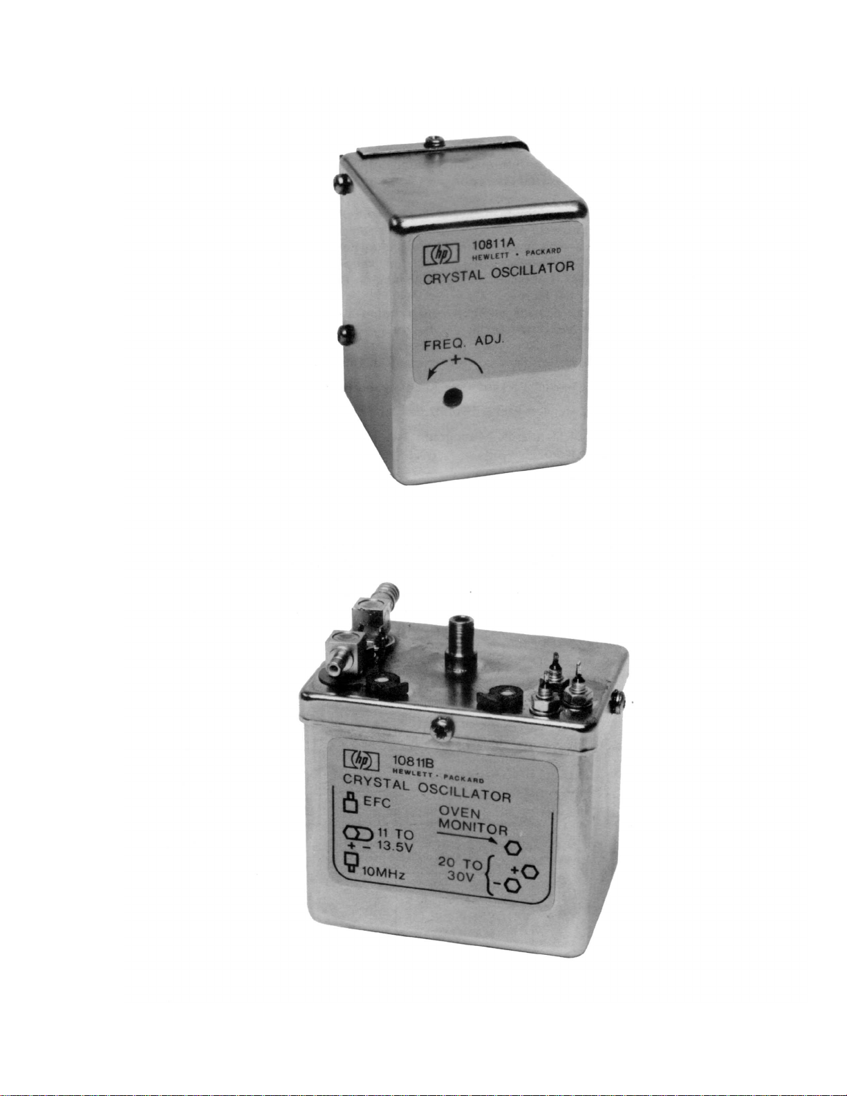
Figure 1-1. 10811A and 108118 Oscillators
1

Model 10811A/B
SECTION I
GENERAL INFORMATION
1-1. INTRODUCTION
1-2. This manual provides information pertaining to the installation, operation, testing, adjustment, and
maintenance of the HP Model 10811A/B Quartz Crystal Oscillator.
and 10811B.
1-3. This manual is divided into eight sections, each covering a particular topic. The topics by section
number are shown below. Sections I, II, III appear in the Operating Instructions Manual. Sections
I through VIII appear in the Operating and Service Manual.
Section Topic
I General Information
II Installation
III Operation
IV Performance Tests
V Adjustments
VI Replaceable Parts
VII Manual Changes
VIII Service
Figure 1-1 shows the 10811A
1-4. SPECIFICATIONS
1-5. Specifications are listed in Table 1-1. These specifications are the performance standards or
limits against which the oscillator may be tested.
1-6. SAFETY CONSIDERATIONS
1-7. The Model 10811A/B Component Oscillator is a Safety Class III product and must be powered
from a source which is electrically isolated from the mains (line circuits). Safety information
pertinent to the operation and servicing of this instrument is included in the appropriate sections
of this manual.
1-8. INSTRUMENTS COVERED BY THIS MANUAL
1-9. Attached to the instrument is a serial number plate. The serial number is in the form 0000A00000.
It is in two parts; the first four digits and the letter are the serial prefix and the last five are the
suffix. The prefix is the same for all identical instruments; it changes only when a change is made
to the instrument. The suffix, however, is assigned sequentially and is different for each
instrument. The contents of this manual apply to instruments with the serial number prefix(es)
listed under Serial Prefix on the title page.
1-10. An instrument manufactured after the printing of this manual may have a serial number prefix that
is not listed on the title page. This unlisted serial number prefix indicates the instrument is
different than those described in this manual. The manual for this new instrument is accompanied
by a yellow Manual Changes supplement. This supplement contains "change information" that
explains how to adapt the manual to the newer instrument.
1-11. In addition to change information, the supplement may contain information for correcting errors in
the manual. To keep this manual as current and accurate as possible, Hewlett Packard
recommends that you periodically request the latest Manual Changes supplement. The
supplement for this manual is identified with the manual print date and part number, both of which
appear on the manual title page. Complimentary copies of the supplement are available from
Hewlett-Packard.
2

Table 1-1. Specifications Table
Model 10811A/B
Frequency Stability
of Terms)
Long Term (Aging Rate): <5 X 10
after 24-hour warm-up. See Note 1.
-7
<1 X 10
Short Term: Refer to tables and figures
above.
/year for continuous operation.
: (See Definition
-10
/day
Environmental Sensitivity:
Temperature: <4.5 X 10⁻⁹ over a -55°C to
71°C range. <2.5 X 1071 °c range.
Operating:-55°C to +71 °C.
Storage: -55°C to X85°C.
Load: <5 X 10
ohm load. <5 X 10
1KΩ load.
-10
Power Supplies:
Oscillator Supply: <2 X 10
change. <100μv ripple and noise required.
Oven Supply: <1 X 10<30 mv ripple and noise required.
Gravitational Field: <4 X 10
shift (turn-over).
Magnetic Field: <-90 dBc sidebands due
to 0.1 millitesla (1 Gauss) rms at 100 Hz.
Humidity (typical): 1 X 10
40°C.
Shock (survival): 30g, 11ms, ½ sinewave.
Altitude (typical): 2 X 10⁻⁹ for 0 to 50,000 ft.
Warmup
10 min. after turn-on within 5 X 10⁻⁹ of final
value, at 25°C and 20 Vdc. See Notes 1 &
2.
9
over a O°C to
for a ±10% change in 50
-10
for a ±25% change in
-10
for 1%
10
for 10% change.
-9
for 2g static
-9
for 95% RH at
Adjustment
Coarse Frequency Range: >±1 X 10⁻⁶ (±
10 Hz) with 18 turn control.
Elec. Frequency Control (EFC): ≥1 X 10
(1 Hz) total, control range -5 Vdc to +5 Vdc.
Output
Frequency: 10 MHz
Voltage: 0.55 ± 0.05 V rms into 50 ohm.
1V rms ±20%, into 1K ohm.
Harmonic Distortion: Down more than 25
dB from output.
Spurious Phase Modulation: Down more
than 100 dB from output (discrete
sidebands 10 Hz to 25 kHz).
Power Requirements
Oscillator Circuit: 11.0 to 13.5 Vdc. 30
mA typical. 40 mA max.
Oven Circuit: 20 to 30 V dc; turn on load
is 42 ohm minimum. Steady-state power
drops to a typical value of 2.0W at 25°C in
still air with 20 Vdc applied.
Connectors
10811A: Mates with CINCH 250-15-30-210
(HP 1251-0160) or equivalent (not
supplied).
10811B: Solder terminals and 5MB Snapon connectors. Mates with Cablewave
Systems, Inc. #700156 or equivalent (not
supplied).
Accessories Available:
Service Manual: HP 10811-90002: (not
supplied). This Manual.
Size:
72 mm X 52 mm X 62 mm, (see Figure
1). (2-13/16" X 2-1/32" X 2-7/16", 14 cu.
-7
in.).
Weight: 0.31 kg (11 oz.)
Definition of Terms
Long-Term Frequency Stability is de-
fined as the absolute value (magnitude)
of the fractional frequency change with
time. An observation time sufficiently
long to reduce the effects of random
noise to an insignificant value is implied.
Frequency changes due to
environmental effects must be
considered separately.
Time Domain Stability
deviation) is defined as the two-sample
deviation of fractional frequency
fluctuations due to random noise in the
oscillator. The measurement bandwidth
is 100 kHz.
Frequency Domain Stability is defined
as the single sideband phase noise-tosignal ratio per Hertz of bandwidth (a
power spectral density). This ratio is
analogous to a spectrum analyzer
display of the carrier versus either
phase modulation sideband.
See "NBS-Monograph 140" for
measurement details.
σ
(τ) (Allan
γ
Notes:
1. For oscillator off-time less than 24 hours.
2. Final value is defined as frequency 24 hours after turn-on.
*Specifications describe the instrument's warranted performance. Supplemental characteristics are
intended to provide information useful in applying the instrument by giving TYPICAL or NOMINAL, but
non warranted performance parameters. Definition of terms is provided at the end of the specification
section.
3

Model 10811A/B
1-12. For information concerning a serial prefix that is not listed on the title page or in the Manual
Changes supplement, contact your nearest Hewlett-Packard office.
1-13. DESCRIPTION
1-14. The HP Model 10811A/B Quartz Crystal Oscillator is an extremely stable, compact, low power
source of 10 MHz. The 10811 A/B has a very fast warm-up time, exhibits excellent temperature
characteristics and has low phase noise and power consumption.
-6
1-15. The 10811A/B has the ability to be adjusted over a range of 20 Hz (2 X 10
sensitive enough to allow adjustment to better than 0.1 Hz (1 X 10
controlled electronically over a 1 Hz (1 X 10
-7
) range with an externally applied voltage to the EFC.
-8
). The frequency can also be
1-16 The 10811A/B is field repairable, thus allowing the oscillator to be quickly placed back into
service.
1-17. The 10811A/B requires two external power supplies. The power supply requirements are listed in
Section II.
1-18. The 10811A and 10811B are identical, except for the connections. The 10811A uses a standard
15 pin printed circuit connector. The 10811B uses filtered-feedthrough terminals for power and
oven monitor, and 5MB subminiature rf snap-on connections for the 10 MHz output and EFC.
1-19. HP Part Number 10811-60101 and 10811-60105
1-20. The 10811-60101 is a 10811A in which phase noise, magnetic field and 2g turn-over are not
specified. The 10811-60101 is physically identical to the 10811A.
-9
1-21. The 10811-60105 is a 10811-60101 with specifications of <1.5 X 10
short-term stability for a 1-second averaging time. The 10811-60105 is physically identical to the
10811A.
for aging and <1 X 10
), yet the control is
-11
for
1-22. RECOMMENDED TEST EQUIPMENT
1-23. The test equipment required to maintain the Model 10811A/B is listed in Table 1-2. Other
equipment may be substituted if it meets or exceeds the critical specifications listed in the table.
4

Model 10811A/B
1
0
/day
(Op
Table 1-2. Recommended Test Equipment
INSTRUMENT REQUIRED CHARACTERISTICS MODEL NO.
1. Frequency Analyzer* Phase noise measurement at 10 MHz 5390 5390A* cannot measure 10811 specs above 10 Hz
2. Frequency Counter** 10 MHz range, HP-IB programmable, 2 ns 5345A** resolution
3. Computing Controller** HP-IB compatible 9835A or 9825A **
4. Frequency Reference Short term stability ≤5x10
Long term stability <5x10
-12
/second 5065A, 5061A
-
tion 004),
or 105A/B***
5. Sampling Voltmeter ±3% accuracy at 10 MHz 3406A
6. General Purpose Bandwidth ≥ 10 MHz 1740A Oscilloscope
7. Frequency Doubler Operates at 10 MHz 10515A
8. Mixer Amplifier** 10 MHz Mixer/50 dB gain K79-59992A**
9. Spectrum Analyzer 10 MHz/70 dB range 8552B/8553B
10. Power Supply 480 mA @ 20V (2 required) 6215A
11. DC Voltmeter Any HP type digital or analog
12. Torque Screwdriver 2-30 inch-lb. (0.2 to 3.4 newton meters) 8730-0012
13. Feedthru Termination 50 ohms 11046B
14. BNC to Miniature Use for 10811B Only 05060-6116 Coax Adapter
15. Test Connector For testing 1 0811A See para. 8-61 *Not needed if items 2, 3, 4 are available. **Not needed if HP 5390A Frequency Stability Analyzer is available. ***If a 105A/B is used, its performance must be verified.
5

Model 10811A/B
SECTION II
INSTALLATION
2-1. INTRODUCTION
2-2. This section contains installation instructions for the 10811 A/B Quartz Crystal Oscillator. Also
included is information about initial inspection and damage claims, preparation for using the
oscillator, and packaging, storage and shipment.
2-3. INITIAL INSPECTION
2-4. Inspect the shipping container for damage. If the shipping container or cushioning material is
damaged, it should be kept until the contents of the shipment have been checked for
completeness and the oscillator has been checked mechanically and electrically. The contents of
the shipment should be as shown in
are given in Section IV. If the contents are incomplete or if there is mechanical damage or defect,
or if the oscillator does not pass the Performance Tests, notify the nearest Hewlett-Packard office.
If the shipping container is damaged, or the cushioning material shows signs of stress, notify the
carrier as well as the Hewlett-Packard office. Keep the shipping materials for the carrier's
inspection. The HP office will arrange for repair or replacement at HP option without waiting for
the claim settlement.
Figure 1-1; procedures for checking electrical performance
2-5. PREPARATION FOR USE
2-6. Power Requirements
2-7. The 10811A/B requires two power sources. One supplies power to the oscillator circuitry and the
other supplies power to the oven heaters.
effect of a change in these voltages on the output frequency.
Table 2-1. Input Voltages/Voltage Coefficients
Input Circuit
Oscillator/
Amplifier
Oven Controller
2-8. Both the 10811A and 10811 B have separate ground return paths for each section (oscillator and
oven circuits). Both grounds may be tied together or operated at any reasonable difference in
potential. Note the oscillator supply ground and 10 MHz output have a common ground return.
The outer housing for both oscillators is tied to this ground point. The 10811 B filtered
feedthrough grounds are also tied to the outer housing.
2-9. In order to maintain the high spectral purity of the 10811A/B output signal, the supply voltages
must be relatively clean. The supply ripple and noise on the 12-volt line (oscillator supply) must
be kept below 100 µV rms and the 20-volt line (oven supply) ripple and noise must be kept below
30 mV rms with both measured in the 10 Hz to 25 kHz range. A 1% change of the 12-volt supply
(oscillator) will cause ≤2
(oven) will cause a ≤1
Required
Voltage
11.0-13.5V dc
Noise <100 µV
20-30V dc 10% <1 X 10
Power drops to steady state value (≈2W)
within 10 min. at 25°C with 20V dc applied.
X 10
-10
X 10
Required Current/Power
30 mA typical, 40 mA max.
Turn on load is 43 ohms minimum
-10
change in output frequency. A 10% change in the 20-volt line
change in output frequency.
Table 2-1 lists the required supply voltages and the
Voltage Coefficients
Voltage
Change
1% <2 X 10
Frequency
Change
-10
-10
6
Model 10811A/B
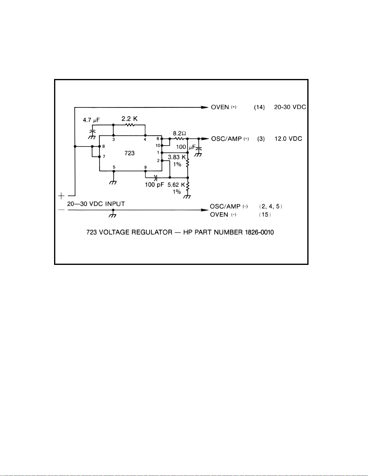
2-10. Single Source Regulated Power Supply
2-11. A single source of +20 to +30V dc with 10% regulation may be used to power both the oven and
oscillator amplifier circuits if a simple IC regulator is used. A suggested circuit is shown in Figure
2-1. The resistor and capacitor connected to terminals 3 and 4 of the IC minimize ripple and noise
in the regulated output.
Figure 2-1. Single Source Regulated Power Supply
2-12. ELECTRONIC FREQUENCY CONTROL (EFC)
2-13. The EFC allows the oscillator to be tuned over a 1 Hz range (1 x 10⁻⁷) by applying -5 to +5 volts
to the EFC input. As the EFC voltage goes positive the output frequency will go lower. Conversely,
as the EFC voltage goes negative, the output frequency will go higher.
2-14. Since noise on the EFC line affects the oscillator's stability (noise appears as FM on the output),
care must be taken to ensure that a relatively noise free EFC voltage source is used. The noise
level must be kept below 100 µV to maintain good stability performance.
2-15. The EFC input should be connected to oscillator circuit ground if not used. A shorting plug (1250-
0911) is supplied with 10811B for this purpose. The EFC input on the 10811A should be
grounded at the printed circuit connector by wiring pins 5 and 6 together.
2-16. 10 MHz FREQUENCY OUTPUT SIGNAL
2-17. The 10 MHz output is ac coupled from a source impedance of approximately 50 ohms. The signal
level is .55 ±.05 into a 50 ohms load or 1-volt ±20% into a 1 K ohm load.
7

Model 10811A/B
2-18. OVEN MONITOR OUTPUT
2-19. The OVEN MONITOR OUTPUT is an indicator of oven warm-up. At initial turn-on (warmup) the
oven monitor will go to approximately 1.5 volts BELOW the oven power supply voltage. After the
oven cuts back, the output will drop to approximately 3.5 volts (at 25°C). The output impedance of
this circuit is 10,000 ohms.
Figure 2-2 shows an oven monitor LED indicator circuit.
Figure 2-2. Oven Monitor LED Circuit
2-20. MATING CONNECTORS AND MOUNTING
2-21. The 10811A Oscillator requires a 15-pin printed circuit connector. The recommended connector is
the CINCH 250-15-30-210 (HP 1251-0160). The 10811A can be secured with two 6-32 screws,
1/4-inch long.
the mechanical mounting dimension for the 10811A and 10811B.
Figure 2-3 shows the power supply connection for the 10811A. Figure 2-5 shows
8
Figure 2-3. 10811A Supply and Output Connections
Model 10811A/B
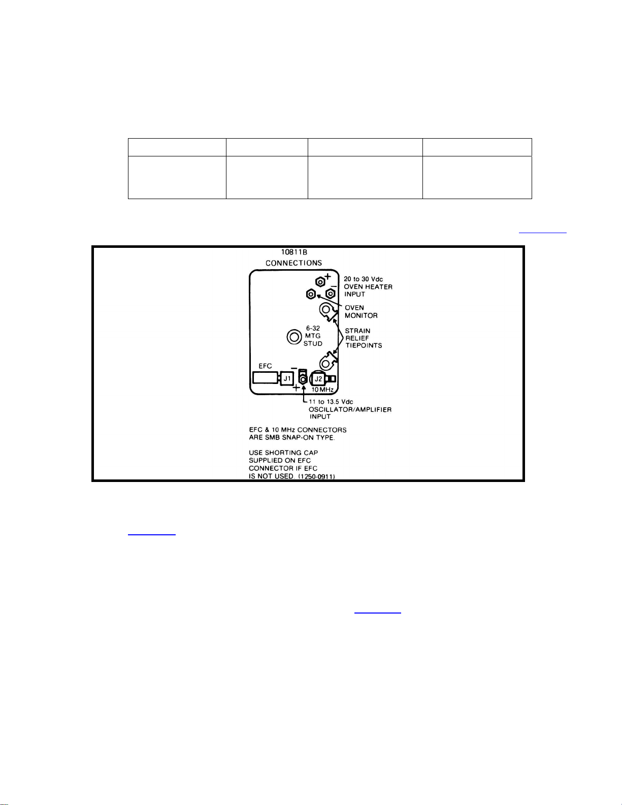
2-22. The 10811 B Oscillator uses solder terminals with filtered feedthrough capacitors for power and
oven monitor outputs and 5MB subminiature rf snap-on connectors for the 10 MHz output and
EFC. The 10811 B also has one internally threaded mounting stud on the bottom cover and two
located on the top. The three studs are threaded for 4-40 screws, 1/4-inch deep. These mounting
studs may be used with vibration isolators such as the LORD #J2924-2-1 (HP Part No. 1520-
0094). However, for ease of testing and interfacing, a 6-pin Amphenol connector is attached. If
you wish to use this connector, the following parts are required to build its mate.
Description Quantity HP Part No. Amphenol Part No. Receptacle 1 1251-4297 221-1508
Pin-Female 5 1251-4734 220-883-03
Guide-Pin 2 1251-0597 221-590
If you do not wish to use the Amphenol connector, it may be easily removed. The 5MB connectors mate
to Cablewave Systems, Inc. #700156 or equivalent HP Part No. 1250-0885 (not supplied).
shows the connections for the 10811 B Oscillator.
Figure 2-4
Figure 2-4. 10811B Supply and Output Connections
2-23. INSTALLATION INSTRUCTIONS
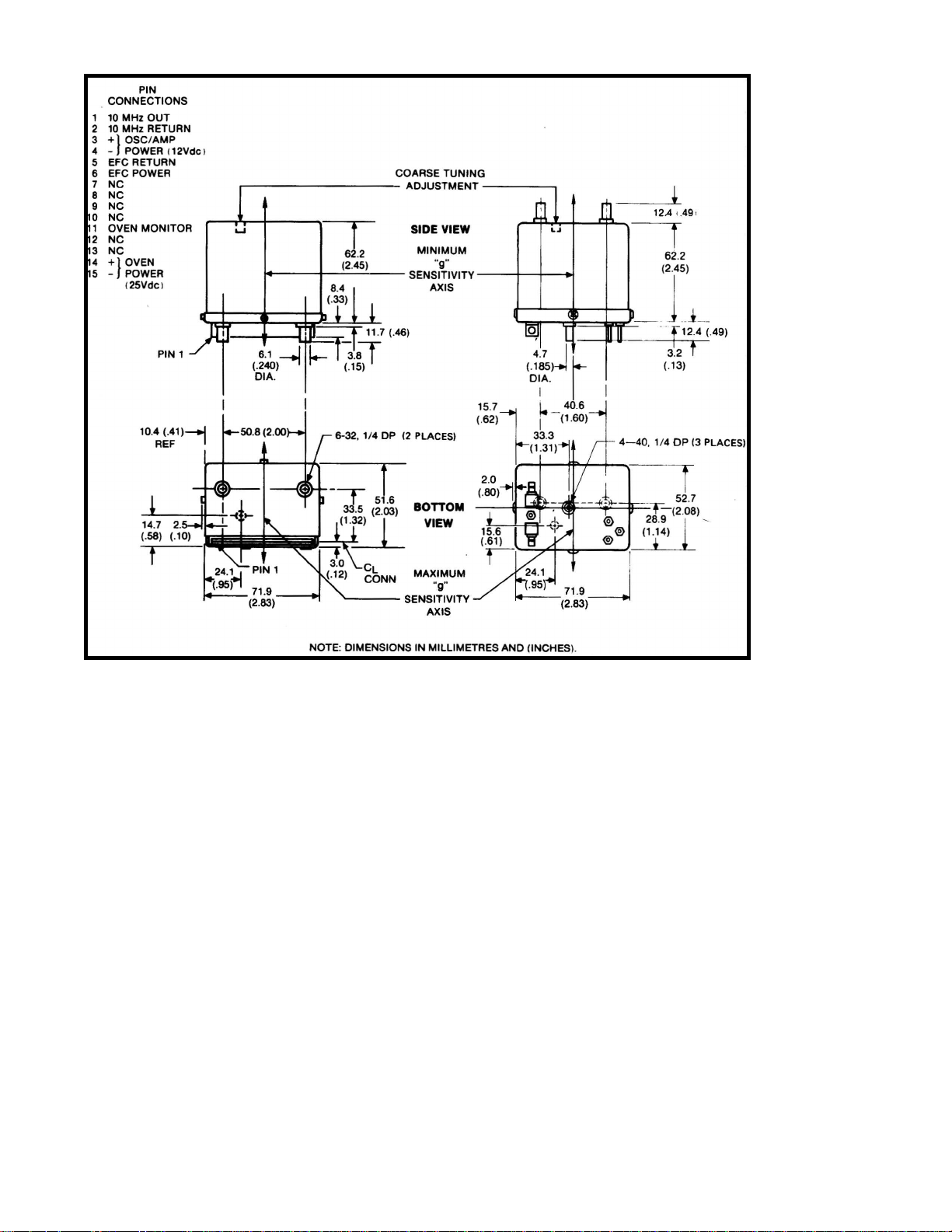
2-24. Figure 2-5 shows the mechanical mounting dimensions of the 10811A/B Oscillators for use in
custom installation. Since all quartz oscillators are sensitive to shock, vibration, radiation fields,
and ambient temperature changes, to obtain the best performance from your 10811A/B, these
factors should be taken into consideration. To optimize performance therefore:
1. The 10811A/B should be mounted in an area that has a minimum amount of vibration or shock
accelerations. In addition, the 10811 A/B should be mounted so that the vibrational forces act
along the "minimum G sensitivity" axis shown in
2. The 10811A/B should be mounted as far as possible from transformers or fan motors that radiate electromagnetic fields.
3. The 10811A/B should be mounted away from the main system airflow in order to isolate it as much as possible from ambient temperature changes.
Figure 2-5.
9
Model 10811A/B
Figure 2-5. Mechanical Mounting Dimensions
2-25. INSTALLATION INSTRUCTIONS (HP INSTRUMENT)
2-26. The 10811 A may be installed in most Hewlett-Packard instruments that already have a 10544A
or 10544B oscillator or has provisions for it. The 10811A may be exchanged directly without any
circuit change or modification.
2-27. If the instrument does not have a 10544A oscillator installed, but is available as an option, then
the service manual for that instrument should be consulted to see if an oscillator support board
(power supplies) is required. Once the support board is installed, the 10811A can be installed in
place of the 10544A. Consult your nearest sales and service office for more details.
2-28. OPERATING ENVIRONMENT
2-29. TEMPERATURE. The 10811A/B may be operated in temperatures from -55°C to +71°C.
2-30. MAGNETIC FIELDS. Sidebands due to 0.1 milliTelsa (1 Gauss) rms at 100 Hz will be down more
than 90 dB from carrier.
-9
X 10
2-32. ALTITUDE. The frequency change will be typically 2
2-33. SHOCK. The 10811A/B can withstand a shock up to 30 Gs for 11 ms, 1/2 sine wave.
for altitudes up to 15.2 km (50,000 ft.).
10

Model 10811A/B
2-34. STORAGE AND SHIPMENT
2-35. Environment
2-36. The 10811A/B may be stored or shipped in environments with the following limits: Temperature ····························· -55°C to +85°C Altitude ······································ 15.2 Km (50,000 feet)
2-37. PACKAGING
2-38. Original Packaging
2-39. Containers and materials identical to those used in factory packaging are available through
Hewlett-Packard offices. If the instrument is being returned to Hewlett-Packard for servicing,
attach a tag indicating the type of service required; return address, model number, and full serial
number. Also, mark the container Fragile to ensure careful handling. In any correspondence, refer
to the instrument by model number and full serial number.
2-40. Other Packaging
2-41. The following general instructions should be used for repacking with commercially available
materials.
1. Wrap instrument in heavy paper or plastic. (If shipping to Hewlett
center, attach tag indicating type of service required; return address, model number, and full
serial number.)
2. Use strong shipping container. A double-wall carton made of 350-pound test material is adequate.
3. Use a layer of shock-absorbing material 70 to 100 mm (3 to 4 inch) thick around all sides of the instrument to provide firm cushioning and prevent movement inside container. Protect control panel with cardboard.
4. Seal shipping container securely.
5. Mark shipping container FRAGILE to insure careful handling.
6. In any correspondence, refer to instrument by model number and full serial number.
-Packard office or service
11

Model 10811A/B
SECTION III
OPERATION
3-1. INTRODUCTION
3-2. This section contains operating information including operating characteristics and operating procedure.
3-3. BASIC POWER-UP DESCRIPTION
3-4. The following paragraph is a basic description of the actions occurring when power is applied to
the oscillator. This description assumes the oscillator is at room temperature (25°C).
3-5. When power is applied to the oscillator, 10 MHz will appear at the output. The oven controller
circuit will go into its full warm-up mode. In this mode the maximum heating power is applied to
the oven mass. The oven mass is a metal casting surrounding the oscillator circuits and crystal.
The OVEN MONITOR output will be approximately 1.5 volts below the oven power supply voltage.
In about 10 minutes, the oven will have heated to the proper temperature. The oven controller will
begin to regulate at this temperature, and the OVEN MONITOR will drop to approximately 3.5
volts. It is normal for the oven current to drop momentarily to a low value when the oven
temperature first reaches maximum. This lasts less than second and is a typical circuit action.
3-6. After the first 10 minutes have passed, the oscillator may be initially adjusted using the following
procedure. The oscillator should be readjusted after 24 hours for maximum accuracy. Periodic
adjustment schedule can be determined by the procedure described in
paragraph 3-10.
3-7. FREQUENCY ADJUSTMENT
3-8. The frequency adjustment is the only periodic adjustment required. This may be initially adjusted
after 10 minutes of warm-up and then readjusted after 24 hours.
3-9. FREQUENCY ADJUSTMENT PROCEDURE
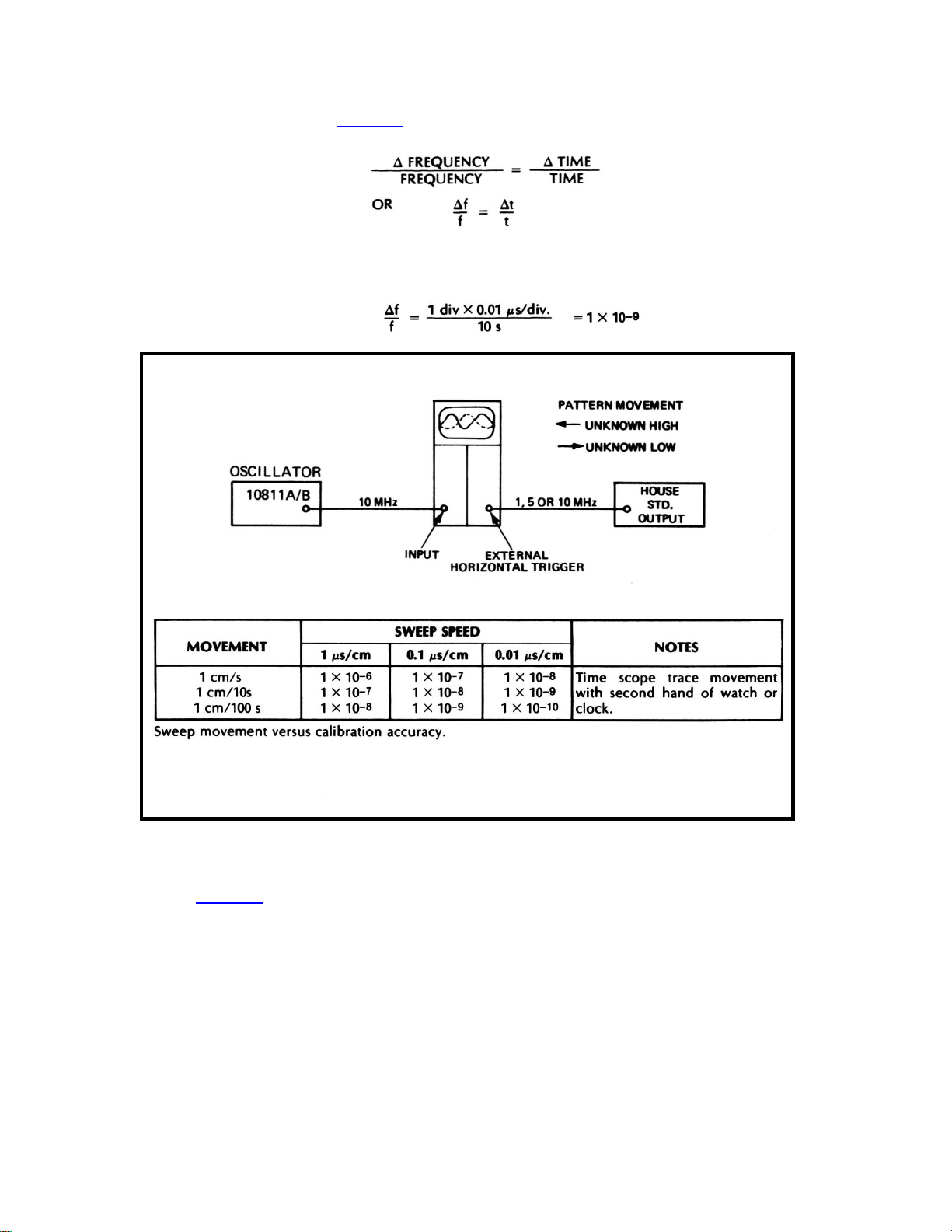
a. Connect reference frequency standard (multiple or submultiple of 10 MHz) to the EXTERNAL
SYNC INPUT of the oscilloscope.
b. Connect oscillator output (10811A/B) to Channel A. Set the sweep speed to .1 μs/div.
c. Set the oscilloscope to EXTERNAL TRIGGER and adjust the oscilloscope so that its sweep is
synchronized to the reference frequency. The pattern will appear to move.
d. Using an insulated tuning tool, adjust oscillator frequency adjustment (FREQ ADJUST on the
10811AIB) for minimum sideways movement of the oscilloscope pattern.
e. By timing the sideways movement (divisions per second on the oscilloscope), the approximate
offset can be determined based on the oscilloscope sweep speed shown in
Figure 3-1
12
Model 10811A/B
f. For example, if the trace moves 1 division in 10 seconds and the sweep speed is 0.01 μs/div., the
oscillator's frequency is 1 x 10
from the calibration,
Table 3-1. The calculation can also be made by the following formula:
-9
different from that of the reference frequency, as can be seen
where Δf/f = offset of the oscillator with respect to the reference standard Δt = the movement of the
oscilloscope pattern (1 div. X .01 μs/div.) = .01, μs t = time required for Δt to occur.
Figure 3-1. Oscillator Adjustment Set-Up
3-10. ACCURACY VS ADJUSTMENT INTERVAL
3-11. Table 3-1 shows the required adjustment interval to maintain a required accuracy. If the aging
rate is known to be 3 x 10
(The specification for aging is <5 X10
can be expected to gradually decrease, and typically will reach 1 X 10
Example:
Known aging rate···········································3 X 10
Maximum allowable error ·····························5 X 10
-10
/day, then a more precise adjustment interval can be determined.
-10
/day, but aging is typically less than this.) The aging rate
-10
/day
-9
-10
/day within 1-year.
13
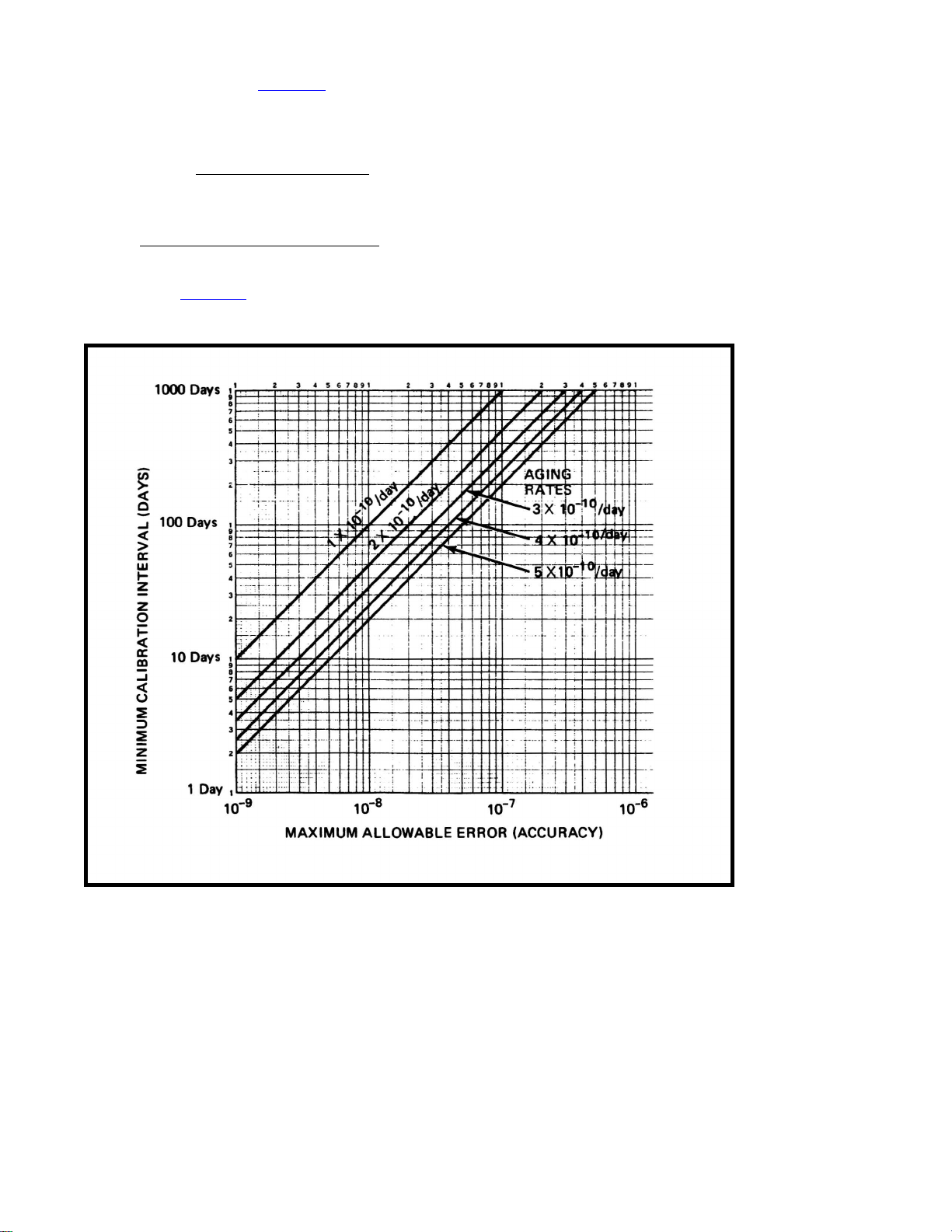
3-12. Find the line on
allowable error (accuracy) on the horizontal axis. Follow the maximum allowable error vertically
until it crosses the oscillator's known aging rate. Move horizontally to the left and read the
minimum calibration interval in days.
Model 10811A/B
Table 3-1 corresponding to the oscillator's aging rate. Then find the maximum
maximum allowable error
known aging rate (per day)
Example:
3-13. From
3-14. The minimum calibration interval may also be determined from the following formula:
-9
5 x 10
3 x 10
(maximum allowable error)
-10
/day (known aging rate) = 16.67 days (~17 days) 3 X 10
Table 3-1, the oscillator should be adjusted approximately every 17 days.
= calibration interval in days
-10
/day (known aging rate)
14
Table 3-1. Accuracy vs Adjustment
Loading...