

Honeywell THX321WFS2001W Professional Install Manual
T10 Pro Smart
33-00423EFS-03
Thermostat with
RedLINK™
THX32 1WFS 20 01W
Programmable Thermostat
Professional Install Guide
Read before installing
Package Includes:
• T10 Pro Smart Thermostat
• UWP™ Mounting System
• Standard Installation Adapter (J-box
adapter)
• Cover Plate – Medium: Size 511/64" X
51/2” X 11/16" (131.4 mm x 139.7 mm
x 17.5 mm)
• RedLINK Wireless Indoor Air Sensor
(QTY 1)
• Screws and Anchors
• Professional Install Guide
• Getting Started Guide
THX321WF2001W depicted.
Othe r model s may vary.
Compatibility
• Compatible with most heating, cooling, and heat pump systems
• Required: 24 VAC power (“C” wire)
• Does not work with electric baseboard heat (120240V)
• Does not work with millivolt systems
• Android or iOS smartphone or tablet
Customer assistance
WEB honeywellhome.com
PHONE 18006333991

2
4
8
7
6
5
M37809
UWP Mounting System installation
1. Open package to find the UWP. See
Figure 1.
2. Position the UWP on the wall. Level and
mark hole positions. See Figure 2.
Drill holes at marked positions, and
then lightly tap supplied wall anchors
into wall using a hammer.
‒ Drill 7/32” holes for drywall.
3. Pull the door open and insert wires
through wiring hole of the UWP. See
Figure 3.
4. Place the UWP over the wall anchors.
Insert and tighten mounting screws
supplied with the UWP. Do not
overtighten. Tighten until the UWP
no longer moves. Close the door. See
Figure 4.
Optional Cover Plate installation
Use the Optional Cover Plate when:
• Mounting the thermostat to an
electrical junction box
• Or when you need to cover paint gap
from the old thermostat.
5. Separate the Junction Box Adapter
from the Cover Plate. See Figure 5.
6. Mount the Junction Box Adapter to
the wall or an electrical box using any
of the eight screw holes. Insert and
tighten mounting screws supplied with
Cover Plate Kit. Do not overtighten.
Make sure the Adapter Plate is level.
See Figure 6.
7. Attach the UWP by hanging it on the
top hook of the Junction Box Adapter
and then snapping the bottom of the
UWP in place. See Figure 7.
8. Snap the Cover Plate onto the
Junction Box Adapter. See Figure 8.
1
3
Use 2x
supplied
screws
#6 5/8”
2
4
Use 3x supplied
screws #8 11/2”
2
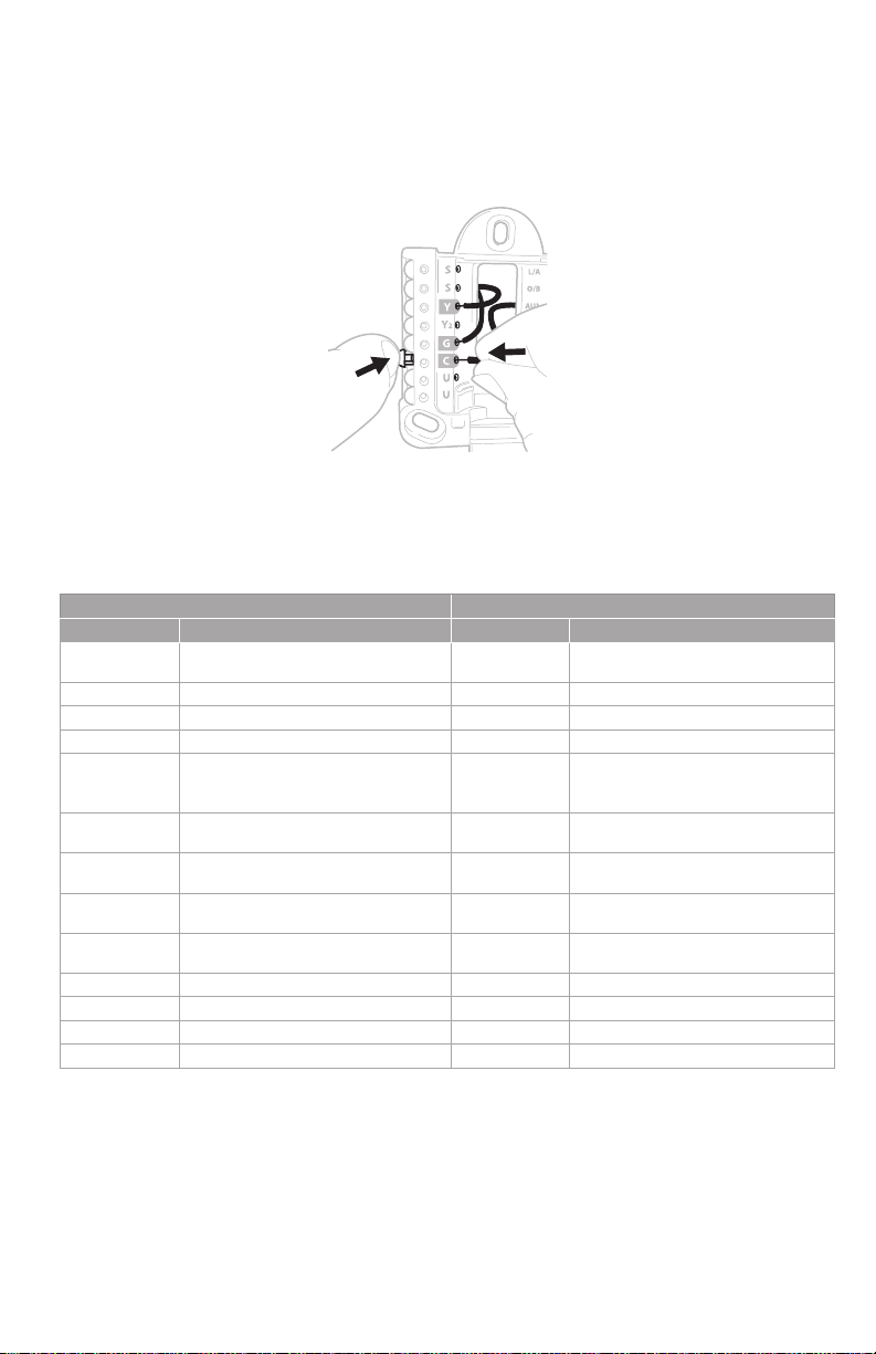
Wiring UWP
Push down on the tabs to put the wires into the inner holes of their corresponding
termi nals on the UWP (one wire per terminal) until they are firmly in place. Gently
tug on the wires to verify they are secure. If you need to release the wires again,
push down the terminal tabs on the sides of the UWP.
This wiring is just an example,
yours may vary.
Terminal designations
Conventional Systems Heat pump systems
Terminal Description Terminal Description
S/S
Y Compressor Stage 1 Y Compressor Stage 1
Y2 Compressor Stage 2 Y2 Compressor Stage 2
G Fan Relay G Fan Relay
C
K*
U/U**
A L/A
W Heat Stage 1 O/B
W2 Heat Stage 2 Aux Backup Heat
R 24 VAC Heating transformer R 24 VAC Heating transformer
Rc 24 VAC Cooling transformer Rc 24 VAC Cooling transformer
* The THP9045A1098 C-wire adaptor is used on heat /cool systems when you only have four wires at
the thermostat and you need a fifth wire for a common wire. Use the K terminal in place of the Y and
G terminals on conventional or heat pump systems to provide control of the fan and the compressor
through a single wire—the unused wire then becomes your common wire. See THP90 45 instructions
for more information.
** See note on Wiring U terminals on the following page.
Input for a wired indoor,
outdoor sensor
24VAC Common wire from
secondary side of cooling
transformer (if 2 transformers)
Connect to K on C-wire
adaptor
Relay for humidifier,
dehumidifier, or ventilator
S/S
C
K*
U/U**
E Emergency Heat
Input for a wired indoor,
outdoor sensor
24VAC Common wire from
secondary side of cooling
transformer
Connect to K on C-wire
adaptor
Relay for humidifier,
dehumidifier, or ventilator
Connect to compressor
monitor
Changeover valve for heat
pumps
3
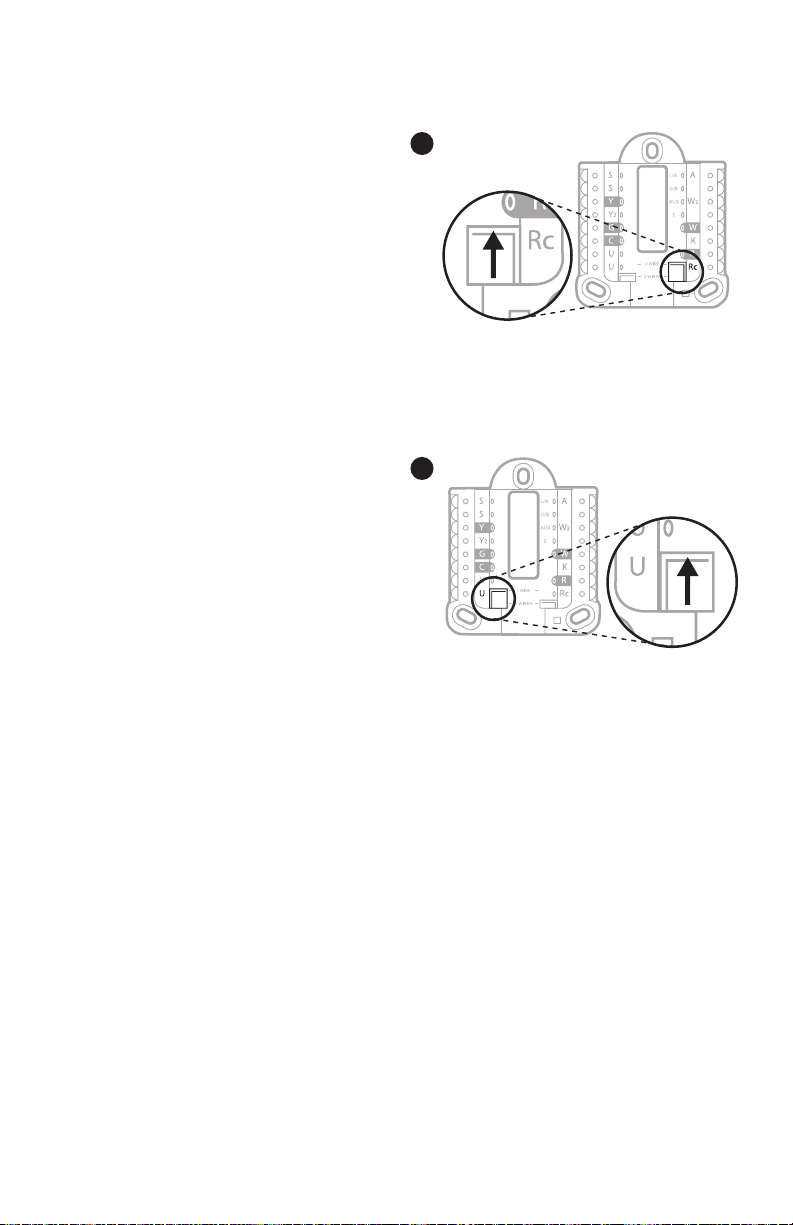
Setting Slider Tabs
Set R Slider Tab, see Figure 9.
• Use built-in jumper (R Slider Tab)
to differentiate between one or two
transformer systems.
• If there is only one R wire, and it is
connected to the R, Rc, or RH terminal
on the old thermostat, set the slider to
the up position (1 wire).
• If there is one wire connected to the R
terminal and one wire connected to the
Rc terminal, set the slider to the down
position (2 wires).
Set U Slider Tab, see Figure 10.
• Use built-in jumper (U Slider Tab) for
IAQ device.
• When the U Slider Tab is in the down
position (2 wires) the U contacts are a
dry set of contacts.
• If your IAQ device is powered by the
cooling transformer, move the U Slider
Tab to the up position (1 wire). When
this is done, the lower U terminal is
internally jumped to the Rc terminal.
In this application, you would hook
up one wire from your IAQ device to
the upper U terminal and the other
to the common side of the cooling
transformer. The 1 wire setting is most
commonly used when using a fresh
air damper for ventilation or using low
speed fan for dehumidification.
• See wiring examples on the next page.
9
10
4
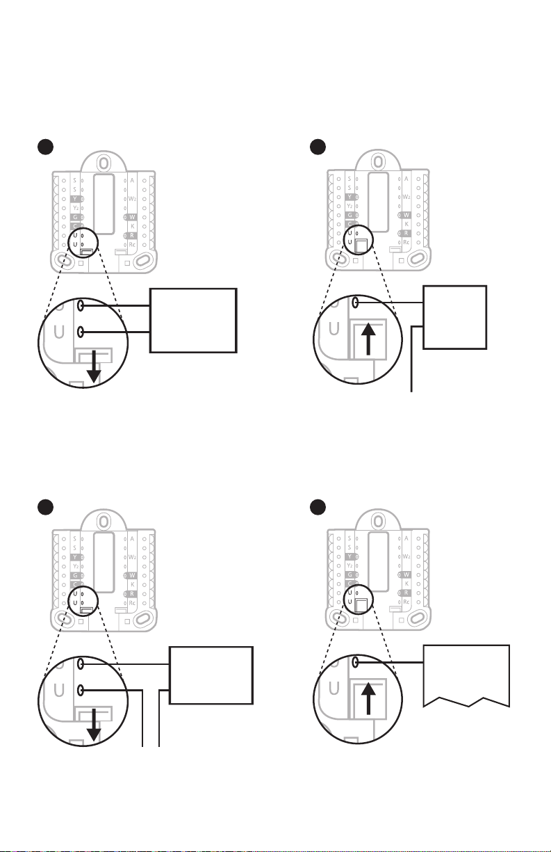
or air-handler
transformer
24 volt transformer
* Label for this terminal
varies by equipment
Whole house humidifier, dehumidifier, or ventilator
Using U Slider Tab
Wired to humidifier,
dehumidifier or ventilator
with built-in transformer.
11 12
Humidifier,
dehumidifier,
or ventilator
Wired to humidifier, ventilator,
or damper powered by external
transformer
13 14
Wired to fresh air damper
powered by furnace
transformer.
Damper
C from furnace
Wired to low speed fan
terminal on HVAC for
dehumidification
R from 24 volt
Humidifier,
dehumidifier,
or ventilator
C (common) from
Dehumidifier*
Furnace or
air-handler
5

Wiring
NOTES:
1. Use 18 to 22 gauge thermostat wire. Shielded cable is not required.
2. Set the R Slider Tab on the UWP to the up position (1 wire) for 1 transformer
systems or the down position (2 wires) for 2 transformer systems. See "Setting
Slider Tabs" on page 4.
3. Set the U Slider Tab as shown in the diagrams on page 4.
Conventional systems
1H/1C System (1 transformer)
R Power
Rc [R+Rc joined by Slider Tab]
Y Compressor contactor
C* 24VAC common
W Heat relay
G Fan relay
Hot Water Relay Panel
R Power
Rc [R+Rc joined by Slider Tab]
W Heat Relay
C* 24VAC common
NOTE: If the panel does not provide 24 volts AC
at R and C, set the slider to down position and
wire a separate transformer to Rc and C.
1H/1C System (2 transformers)
R Power (heating transformer)
Rc Power (cooling transformer)
Y Compressor contactor
C* 24 VAC common from cooling transformer
W Heat relay
G Fan relay
2H/2C System (1 transformer)
R Power
Rc [R+Rc joined by Slider Tab]
Y Compressor contactor (stage 1)
C* 24VAC common
W Heat relay (stage 1)
G Fan relay
W2 Heat relay (stage 2)
Y2 Compressor contactor (stage 2)
* This thermostat requires a C-Wire. If a C-Wire is not available, use C-Wire adapter accessory
THP9045A1098.
Heat-only System with Fan
R Power
Rc [R+Rc joined by Slider Tab]
C* 24VAC common
W Heat relay
G Fan relay
Cool-only System with Fan
R Power
Rc [R+Rc joined by Slider Tab]
Y Compressor contactor
C* 24VAC common
G Fan relay
6

Heat pumps systems
1H/1C Heat Pump System
R Power
Rc [R+Rc joined by Slider Tab]
Y Compressor contactor
C* 24VAC common
O/B Changeover valve
G Fan relay
2H/1C Heat Pump System
R Power
Rc [R+Rc joined by Slider Tab]
Y Compressor contactor
C* 24VAC common
O/B Changeover valve
G Fan relay
Aux Auxiliary heat**
E Emergency heat relay**
L Heat pump fault input
2H/2C Heat Pump System
R Power
Rc [R+Rc joined by Slider Tab]
Y Compressor contactor (stage 1)
C* 24VAC common
O/B Changeover valve
G Fan relay
Y2 Compressor contactor (stage 2)
L Heat pump fault input
3H/2C Heat Pump System
R Power
Rc [R+Rc joined by Slider Tab]
Y Compressor contactor (stage 1)
C* 24VAC common
O/B Changeover valve
G Fan relay
Aux Auxiliary heat**
E Emergency heat relay**
Y2 Compressor contactor (stage 2)
L Heat pump fault input
NOTE: Do NOT use W for heat pump applications. Auxiliary heat must wire to AUX or E.
* This thermostat requires a C-Wire. If a C-Wire is not available, use C-Wire adapter accessory
THP9045A1098.
** If you do not have separate wires for the Aux and E terminals, connect the wire to the Aux terminal.
7
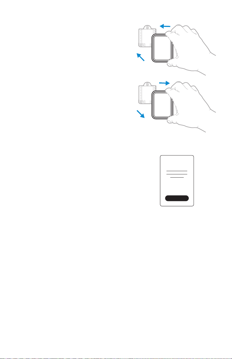
Mounting thermostat
1. Push excess wire back into the wall opening.
2. Close the UWP door. It should remain
closed without bulging.
3. Align the UWP with the thermostat, and
push gently until the thermostat snaps in
place.
Note: If you used the Optional Cover Plate
shown on page 2, remove the gray trim
ring from the thermostat before step 3. Then
align the thermostat with cover plate and push
gently until the thermostat snaps into place.
Note: If needed, gently pull to remove the
thermostat from the UWP
Installer setup
The display will walk you through equipment setup,
connecting to wireless sensors and connecting to
WiFi.
The final step in the setup is a place you can enter
your company name and contact information as
well as your Contractor PRO™ number.
That contact information will be displayed with
alert or reminder messages to keep you connected
to your customer.
Enter your company’s Contractor PRO™ account
number to participate in periodic promotions. Earn
incentives such as bonus points for every T10
Pro Smart thermostat you install during eligible
promotional periods. Your account number is
an 8-digit number that includes a leading zero
(example 01234567).
For questions on this bonus or membership to the
Contractor PRO™ loyalty program, contact us at
18009194835 or contractorpro@resideo.com.
Welcome!
8
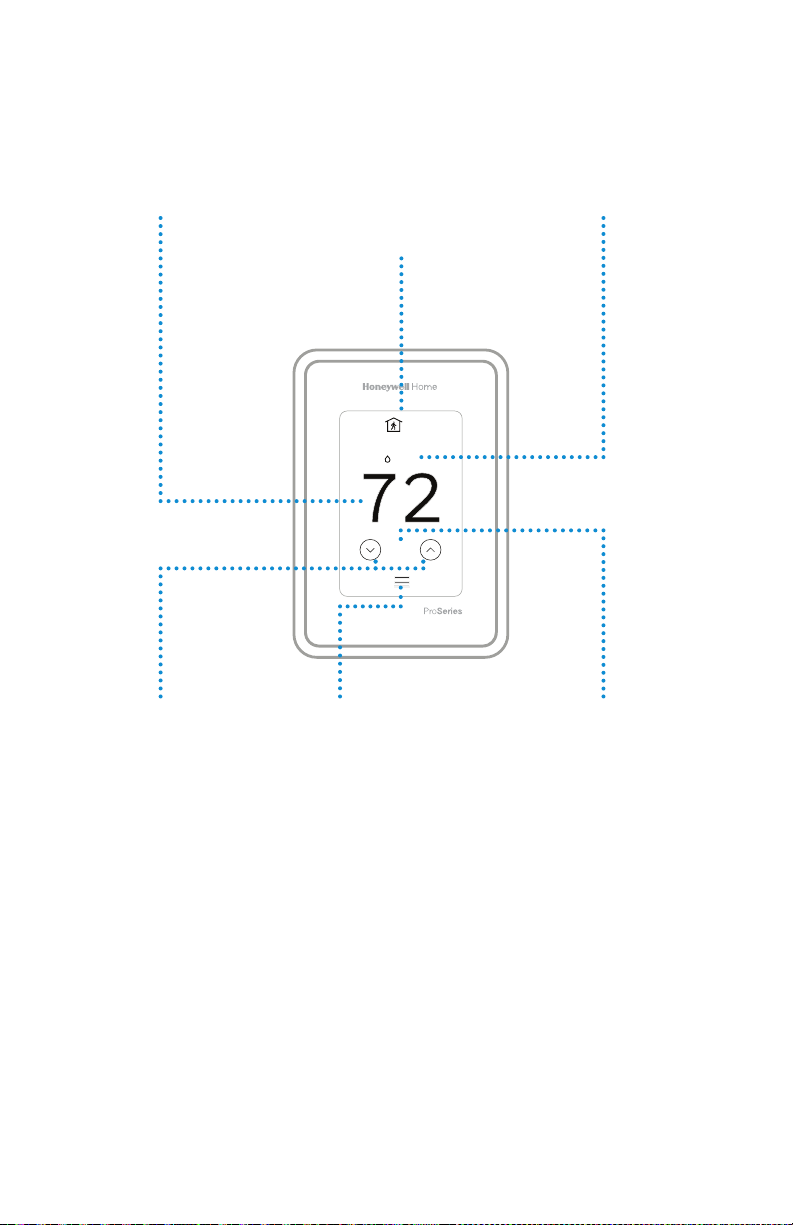
How to use your thermostat
The screen will wake up by pressing the center area of the displayed temperature.
Indoor Temperature
Displays the current
indoor temperature.
Adjust Temperature
Touch the up and
down arrows to
set your desired
temperature.
Current Priority
Displays the type of
priority and number
of rooms being
prioritized.
2
18%
74
Menu
Contains features
such as mode, fan,
schedule, priority,
and other thermostat
settings.
Indoor Humidity
Displays the current
indoor humidity.
Desired
Temperature
Displays the desired
temperature.
9

How to use Priority
Priority creates an average temperature in your home based on specific rooms. This
allows you to prioritize comfort where you want it.
Selected Rooms
Rooms you manually select create an average
temperature in your home.
72 72
72 72
Active Rooms
Rooms with detected motion are automatically selected
to create an average temperature in your home.
Room without Activity
No motion is detected. Will not contribute to the average
temperature.
Room with Activity
Motion is detected. Will contribute to the average
temperature.
Unselected Room
Will not contribute to the average temperature.
Selected Room
Will contribute to the average temperature.
72 72
72 72
10

How to find more options
1. Touch the menu button.
2. Scroll up and down for more options.
Menu options include
Installer Setup
• System type
• IAQ control (hum, dehum, vent) reminders
Installer Test
• Turn on heat, cool, or IAQ equipment
Devices & Sensors
• View, add, or remove RedLINK indoor sensors
• Identity wireless sensors
• Add wireless sensors Device Information
1 2
Installer Options
Thermostat Information
• MAC ID number
• IP address
• Date code
• Model number
• Build date
• Stat app
• Firmware version
• Stat app boot #
• Hardware
Dealer Information
Finding date code (pass code) for installer setup.
Open the Menu icon, and choose Thermostat Information. Write down date code.
11
Alerts and notifications
1. The red dot above the Menu
icon indicates an active alert or
notification. Touch the Menu
icon to view active Alerts &
Notifications.
2. Touch Notifications to open this
menu.
3. Touch the alert message to see
more information about the alert.
1 2
Notifications
3
Notifications
Set the Date
and Time
Set the Date
and Time
12

Troubleshooting
Screen is blank
Screen is difficult to
read
Heating or cooling
system does not
respond
Temperature
settings do not
change
“Cool On” or “Heat
On” is flashing
• Check circuit breaker and reset if necessary.
• Make sure power switch at heating and cooling system is
on.
• Make sure furnace door is closed securely.
• Check setting in MENU/ Preferences / Inactive backlight
brightness or Inactive sleep backlight brightness
• Touch MENU to go to system mode. Set to heat. Make sure
the heat setpoint is above the room temperature.
• Touch MENU to go to system mode. Set to cool. Make sure
the cool setpoint is below the room temperature.
• Check circuit breaker and reset if necessary.
• Make sure power switch at heating & cooling system is on.
• Make sure furnace door is closed securely.
Make sure heating and cooling temperatures are set to
acceptable ranges:
• Heat: 40 °F to 90 °F (4.5 °C to 32.0 °C)
• Cool: 50 °F to 99 °F (10.0 °C to 37.0 °C)
• Compressor protection feature is engaged. Wait 5 minutes
for the system to restart safely, without damage to the
compressor.
Aux heat runs in
cooling
Cool runs with a call
for heat
Heat runs with cooling
Sensor will not
connect
• For heat pump systems, verify there is not a wire attached
to W on UWP systems. See “Heat pumps systems" on page
7.
• For heat pump systems, verify there is not a wire attached
to W on UWP systems. See “Heat pumps systems" on page
7.
• Verify there is not a wire attached to W for heat pump
systems. See "Wiring" on pages 67.
• Press and hold Connect on the wireless sensor for 15
seconds. The LED will turn Amber. Return to the thermostat
menu and press Menu > Devices and Sensors. Follow the
on-screen instructions to add the sensor.
13
CAUTION: ELECTRICAL HAZARD
Can cause electrical shock or equipment damage. Disconnect power before beginning installation.
CAUTION : EQUIPMENT DAMAGE HA ZARD
Compressor protection is bypassed during testing. To prevent equipment damage, avoid cycling the compressor
quickly.
CAUTION: MERCURY NOTICE
If this product is replacing a control that contains mercury in a sealed tube, do not place the old control in the trash.
Contact your local waste management authority for instructions regarding recycling and proper disposal.
Specifications
Temperature Ranges
Heat: 40 °F to 90 °F (4.5 °C to 32.0 °C)
Cool: 50 °F to 99 °F (10.0 °C to 37.0 °C)
Operating Ambient Temperature
32 °F to 120 °F (0 °C to 48.9 °C)
Shipping Temperature
20 °F to 120 °F (28.9 °C to 48.9 °C)
Operating Relative Humidity
5% to 90% (non-condensing)
Electrical Ratings
Terminal Voltage
W Heating 2030 Vac 0.021.0 A
(Powerpile) 750 mV DC 100 mA DC
W2 (Aux) Heating 2030 Vac 0.021.0 A
E Emergency Heat 2030 Vac 0.020.5 A
Y Compressor Stage 1 2030 Vac 0.021.0 A
Y2 Compressor Stage 2 2030 Vac 0.021.0 A
G Fan 2030 Vac 0.020.5 A
O/B Changeover 2030 Vac 0.020.5 A
L/A Input 2030 Vac 0.020.5 A
U 2030 Vac 0.020.5 A
Power Consumption
3 VA
(50/60Hz)
Running
Current
Physic al Dimensions in inche s (mm) (H x W x D)
T10 PRO WiFi Thermostat:
4.9" x 3.7" x 0.93" (125.4 x 94.1 x 23.68)
UWP Mounting System (included):
29/32" x 213/64" x 243/64" (58 x 56 x 10)
Standard Installation Adapter (included):
329/32" x 357/64" x 21/32" (99 x 99 x 17)
Cover Plate – Medium (included):
511/64" x 51/2" x 11/16" (131.4 x 139.7 x 17.5)
Cover Plate – Large (THP2400A1068):
67/64" x 67/64" x 9/32" (155 x 155 x 7)
5-year limited warranty
For Warranty information go to
http://honeywellhome.com
Regulatory information
FCC REGULATIONS
§ 15.19 (a)(3)
This device complies with part 15 of the FCC Rules. Operation
is subject to the following two conditions:
1 This device may not cause harmful interference, and
2 This device must accept any interference received,
including interference that may cause undesired operation.
IC REGULATIONS
RSSGEN
This device complies with Industry Canada’s license-exempt
RSSs.
Operation is subject to the following two conditions:
1 This device may not cause interference; and
2 This device must accept any interference, including
interference that may cause undesired operation of the
device.
FCC Warning (Part 15.21) (USA only)
Changes or modifications not expressly approved by the party
responsible for compliance could void the user’s authority to
operate the equipment.
The product should not be disposed of with other household
waste. Check for the nearest authorized collection centers
or authorized recyclers. The correct disposal of end-of-life
equipment will help prevent potential negative consequences
for the environment and human health.
Resi deo Inc., 1 985 Dougla s Drive Nor th
Golden Valley, MN 55422
www.resideo.com
©2019 Resideo Technologies, Inc. This product is manufactured by Resideo Technologies, Inc., Golden Valley, MN, 1-800-633-3991
The Honeywell Home trademark is used under license from Honeywell International Inc. All rights reserved.
33-00423EFS—03 M.S. Rev. 03-19
Printed in U.S.A.
 Loading...