

Page 1
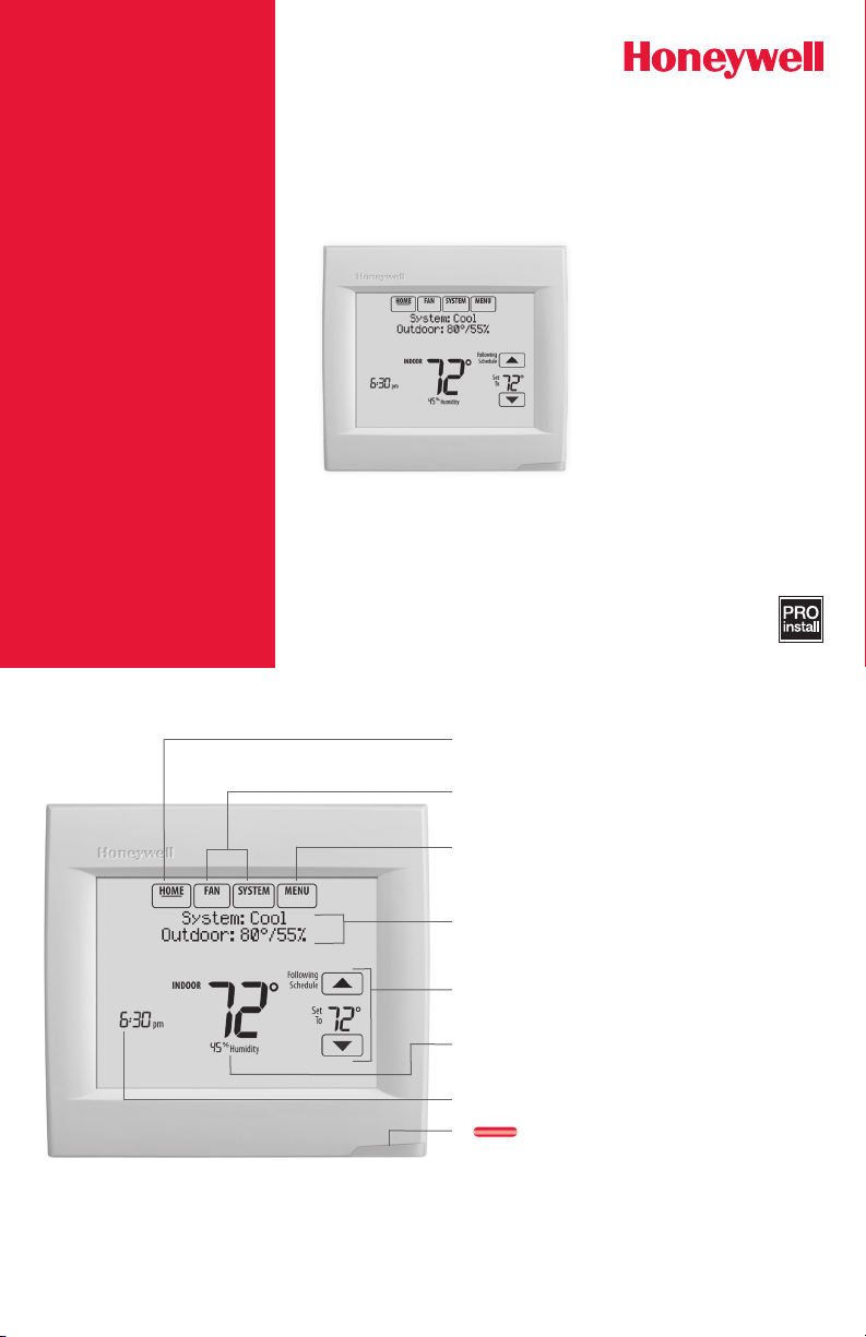
Reference to key features
* Password is the date code.
Wi-Fi VisionPRO® 8000
Installation Guide
Current display. Underlined label
signifies the current display.
Mode control buttons. Use to change
settings for Fan or System Heat/Cool.
Menu. Select options to: set schedules,
view equipment status, change IAQ
settings, access installer options*, etc.
Current status. Shows system mode
(heat/cool), outdoor temperature and
humidity.
Current schedule. Shows desired
temperature and schedule status.
Indoor conditions. Shows indoor
temperature and humidity.
Current Time.
Alert Light. On when alert
message is active or system is set to
Em Heat.
Page 2
1-855-733-5465
http://yourhome.honeywell.com
Honeywell, Golden
TH8321WF1001
M35343
Getting started
Follow these basic steps to install this thermostat,
set installer options, and connect to the Wi-Fi
network.
Thermostat (back view)
RoHs Compliant
Conformité RoHs
Assembled in Mexico
Assemblé au Mexique
1524
1
TH8321WF1001
Residential/Résidentiel
1-800-468-1502
http://yourhome.honeywell.com
Commercial/Commerciale
1-888-245-1051
http://customer.honeywell.com
Honeywell, Golden Valley, MN 55422
Installing the thermostat
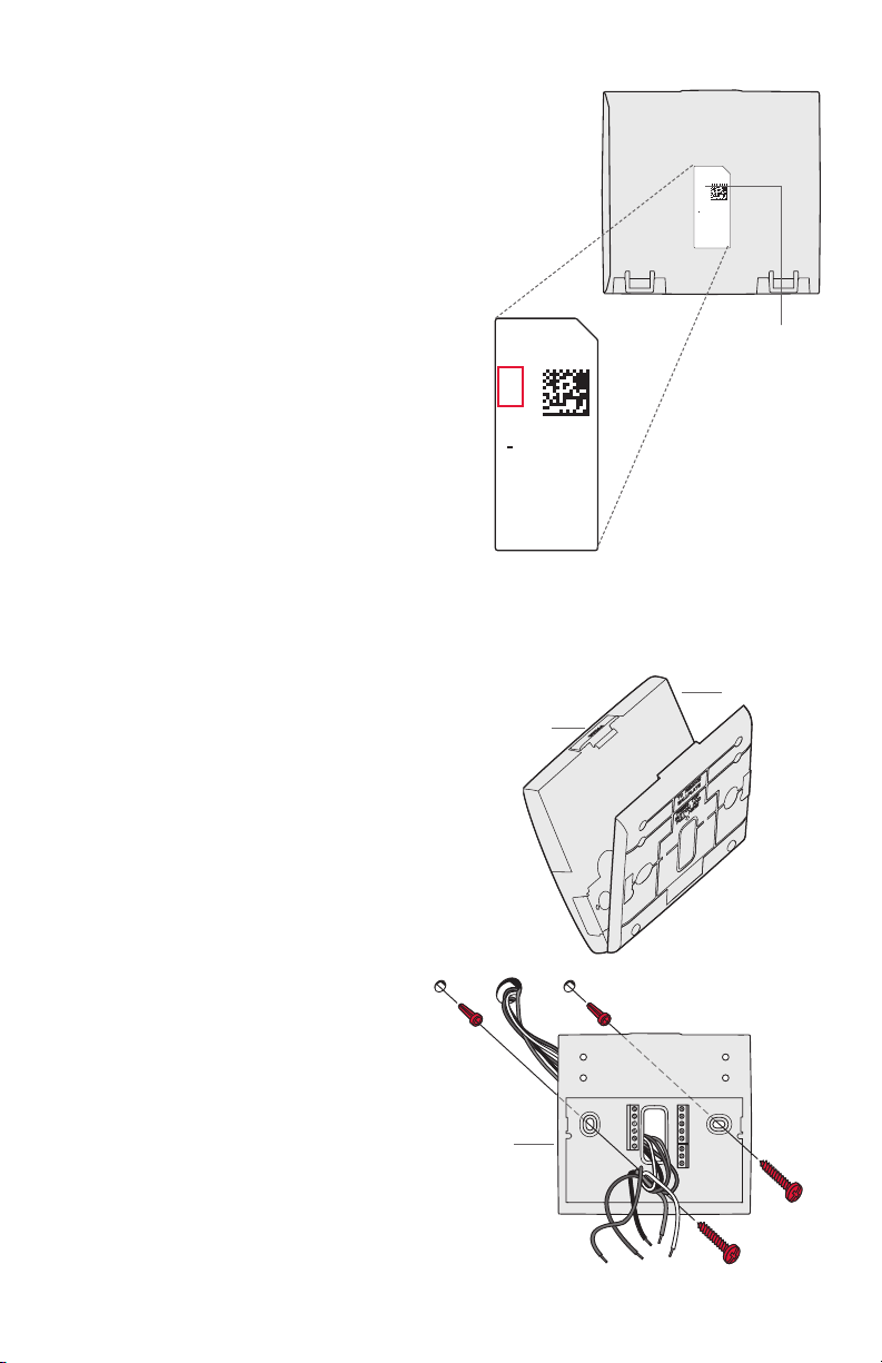
1 Separate wallplate from thermostat.
Press button on top and pull to remove
the wallplate.
RoHs Compliant
Conformité RoHs
Assembled in Mexico
Assemblé au Mexique
1524
1
Button
Password
(Date Code)
Valley, MN 55422
Thermostat
Wallplate
(back view)
2 Mount wallplate as shown.
Mount new wallplate using screws
and anchors included with the
thermostat.
Drill 3/16-in holes for drywall.
Drill 7/32-in holes for plaster.
2
Wallplate
S1
C
K
C
R
R
U1
U1
U2
U2
S1
S1
S1
W
O/B
Y
Y
G
G
AUX
W2
-E
Y2
Y2
L/A
A
Page 3
CONVENTIONAL
CONVENTIONAL
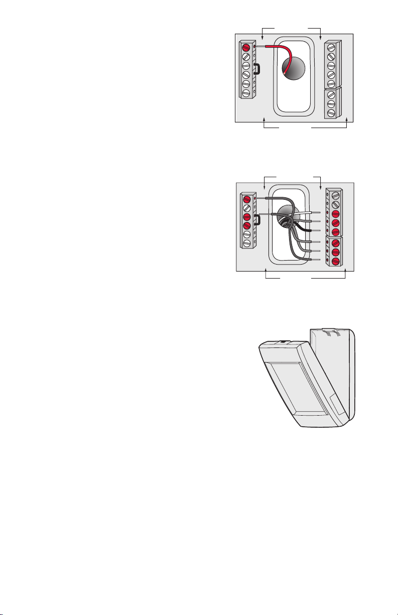
3 Connect power.
24VAC power is required. Connect
common side of transformer to C
terminal.
4 Wire the thermostat.
Refer to the table and wiring
diagrams on the next page.
a Turn on 24VAC NOW.
24VAC (C wire) is required.
C
K
RC
R
U1
U1
U2
U2
HEAT PUMP
C
K
RC
R
U1
U1
U2
U2
HEAT PUMP
S1
S1
S1
S1
O/B
W
Y
Y
G
G
AUX
W2
-E
Y2
Y2
A
L/A
S1
S1
S1
S1
O/B
W
Y
Y
G
G
AUX
W2
-E
Y2
Y2
A
L/A
5 Mount thermostat on wallplate.
Align thermostat at bottom and
snap into place as shown.
3
Wallplate
Thermostat
Page 4
Terminal Designations
SYSTEM
1
1
SYSTEM
TRANSFORMER
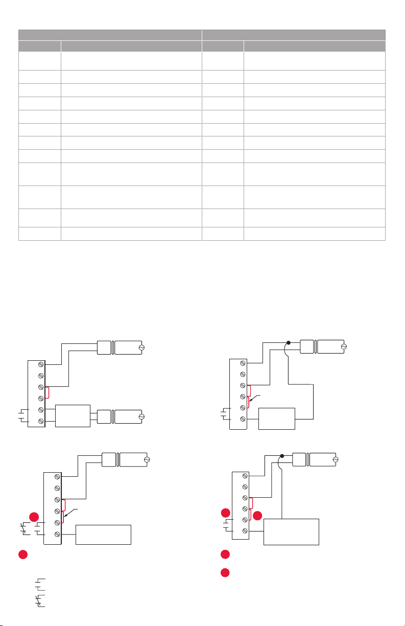
Conventional System Heat Pump
Terminal Description Terminal Description
Common wire from secondary side of
C
cooling transformer (if 2 transformers).
Rc* Cooling power. Rc Cooling power.
R* Heating power. R Heating power.
W Heat Stage 1 O/B Changeover valve for heat pumps.
W2 Heat Stage 2 AUX-E Backup Heat/Emergency Heat
Y Compressor Stage 1 Y Compressor Stage 1
Y2 Compressor Stage 2 Y2 Compressor Stage 2
G Fan Relay G Fan Relay
Connect to Economizer Module or
A
Lighting Panel (TOD).
U1 / U1
S1 / S1
Universal relay for humidification,
dehumidification, ventilation, or a stage of
heating/cooling.
Universal input for a wired indoor, outdoor
or discharge sensor.
U1 / U1
S1 / S1
K** Connect to K on Wire Saver module. K** Connect to K on Wire Saver module.
Common wire from secondary side of
C
cooling transformer.
Connect to Compressor Monitor, Zone
L/A
Panel, Economizer Module or Lighting
Panel (TOD).
Universal relay for humidification,
dehumidification, ventilation, or a stage of
heating/cooling.
Universal input for a wired indoor, outdoor
or discharge sensor.
* Remove factory installed jumper for two transformer systems.
** The THP9045A1023 Wire Saver module is used on heat/cool systems when you only have four wires at the thermostat and you
need a fifth wire for a common wire. Use the K terminal in place of the Y and G terminals on conventional or heat pump systems to
provide control of the fan and the compressor through a single wire—the unused wire then becomes your common wire. See THP9045
instructions for more information.
TRANSFORMER
C
THERMOSTAT
C
K
R
C
R
U1
U1
OR
POWERED
HUMIDIFIER,
DEHUMIDIFIER
OR VENTILATOR
THERMOSTAT
C
K
C
R
R
1
U1
U1
Wire the thermostat universal relay to the low speed fan
for dehumidication control at the equipment. The
thermostat relay can be set to normally open or
normally closed in the thermostat installer setup.
R
FIELD INSTALL JUMPER
BETWEEN R AND U1
DEHUMIDIFICATION
WITH LOW SPEED FAN
24
VAC
HUM, DEHUM OR
TRANSFORMER
24
VAC
C
24
VAC
R
VENT
120
VAC
120
VAC
120
VAC
Normally open, dry contacts
Normally closed, dry contacts
NON-POWERED HUMIDIFIER, DEHUMIDIFIER OR VENTILATORPOWERED HUMIDIFIER, DEHUMIDIFIER OR VENTILATOR
THERMOSTAT
C
K
R
C
FIELD INSTALL JUMPER
R
BETWEEN R AND U1
U1
NON-POWERED
U1
CONNECTING A HEAT OR COOL STAGE TO U1DEHUMIDIFICATION WITH LOW SPEED FAN
THERMOSTAT
1
2
HUMIDIFIER,
DEHUMIDIFIER
OR VENTILATOR
C
K
R
C
R
2
U1
U1
U1 terminals are normally open dry contacts when set
up for a stage of heating or cooling.
You must install a eld jumper if the stage of heating
or cooling is powered by system transformer. Do NOT
install a eld jumper if the stage of heating has its own
transformer.
HEAT STAGE 3, COOL
STAGE 3, BACKUP HEAT
STAGE 2 FOR HEAT
PUMPS, OR GEOTHERMAL
RADIANT HEAT
C
R
TRANSFORMER
C
24
VAC
R
SYSTEM
TRANSFORMER
24
VAC
120
VAC
VAC
120
4
Page 5
Performing installer setup
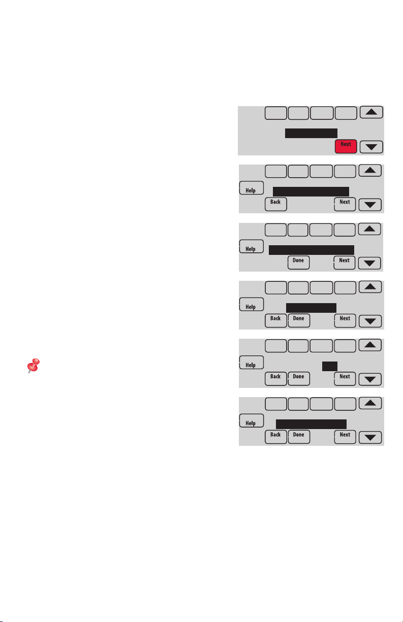
Setup options define the type of system you are installing and preferences for the
display.
1 Follow prompts on the screen to select the appropriate options. Among the
screens you might see wil be options for:
1.1 Application, either Residential or
Commercial.
APPLICATION
residential
1.2 Thermostat Name, which will enable
you to identify it if you’re installing more
than one thermostat (for a zoned HVAC
THERMOSTAT NAME
THERMOSTAT
application, for instance).
1.3 Thermostat Type, either programmable
or not, depending on preference.
THERMOSTAT TYPE
programmable
1.4 Temperature scale, either Fahrenheit or
Celsius.
TEMPERATURE SCALE
fahrenheit
1.5 Any Outdoor Air Sensors installed.
NOTE: If you are using a Wired Outdoor
Sensor or the outdoor temperature from the
OUTDOOR AIR
SENSOR: no
Wi-Fi connection to lockout the compressor
or Auxiliary heat, select Yes to see the
installer options for lockout temperatures.
1.6 The type of heating system.
HEATING SYSTEM
conv. forced air
1.7 For all installer options, press the s or
t buttons to change the option.
1.8 Press Next to move to the next setting, and Done when setup is complete.
5
Page 6
Connecting to Wi-Fi
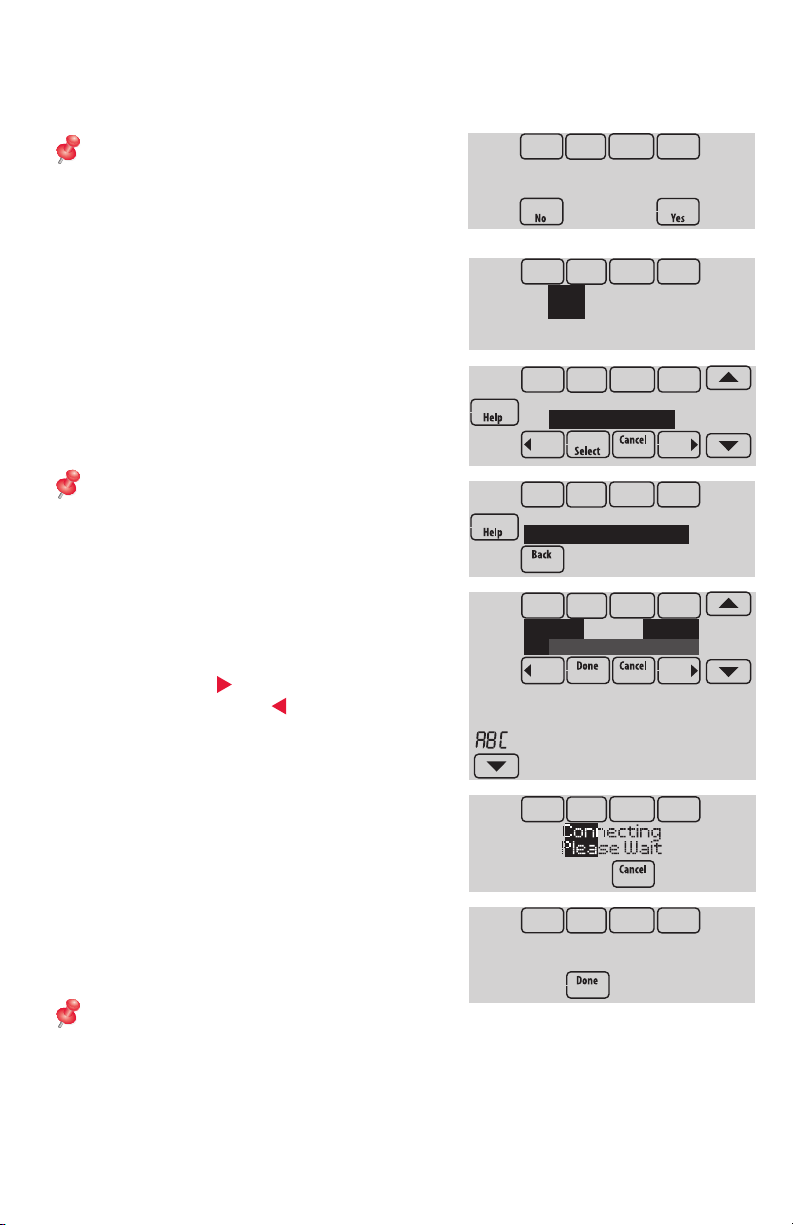
After installer setup, you will be prompted to connect to a Wi-Fi network.
NOTE: If you select No, the homeowner
can connect to the Wi-Fi network later. (See
“Connecting to Wi-Fi later” on page 8
or in the User’s Guide.) The thermostat will
display its Home screen and thermostat
setup is complete.
Connect to a
Wi-Fi network now?
1 Connect to the Wi-Fi network now.
1.1 Press Yes.
The thermostat will scan for available
Wi-Fi networks.
1.2 Use the arrow buttons to scroll up/
down or left/right. Press the Wi-Fi
network name, then press Select.
NOTE: If the Wi-Fi network name is hidden,
see “Connecting to a hidden Wi-Fi network”
on page 10.
1.3 When prompted, press the screen to
edit the password (if necessary).
1.4 Enter the password.
Press the s or t buttons to change
the letter or number.
Press the
button to move to the next
character, or the button to move to
the previous character.
Use the s or t buttons at the bottom
to change letter case.
Press Done when complete.
1.5 The screen will let you know when the
connection is successful. Press Done
when the connection is successful.
If the connection is not successful,
the screen will explain why not. See
“Unsuccessful connection” on page
9. Follow instructions on the screen
to try again.
NOTE: Press the Help button for more
information about an unsuccessful connection.
Finding Networks
Please Wait
Select Wi-Fi Network
Your Network
Enter Password
Press Here to Edit
Delete Space
AC
Connection
Successful
6
Page 7
1-855-733-5465
http://yourhome.honeywell.com
Honeywell, Golden
TH8321WF1001
M35343
2 The homeowner must have a Total Connect Comfort account.
2.1 Have the homeowner go to
www.mytotalconnectcomfort.com and
Register at:
follow the instructions to login or create
an account.
2.2 Press the t button to display Wi-Fi
signal strength, status, IP address, MAC and CRC.
2.3 Note the Thermostat MAC and CRC; they will be needed during registration.
Or, refer to the User’s Guide.
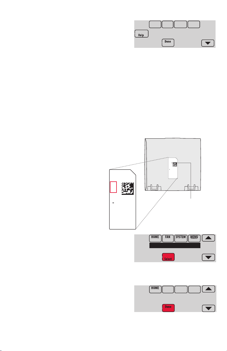
Finding the password (Date Code)
• To make changes to Installer Setup
• To perform an Installer Test
Finding the password
You can find the date code
on the back of the thermostat,
or touch Menu, select Dealer Information,
and scroll to the bottom to see Date Code.
1 Touch Menu.
2 Select Dealer Information.
3 Scroll down to see the Date Code.
RoHs Compliant
Conformité RoHs
Assembled in Mexico
Assemblé au Mexique
1524
1
Valley, MN 55422
Thermostat (back view)
RoHs Compliant
Conformité RoHs
Assembled in Mexico
Assemblé au Mexique
1524
1
TH8321WF1001
Residential/Résidentiel
1-800-468-1502
http://yourhome.honeywell.com
Commercial/Commerciale
1-888-245-1051
http://customer.honeywell.com
Honeywell, Golden Valley, MN 55422
Password
(Date Code)
Dealer Information
Installer Options
TH8321WF1001
Date Code: 1524
7
Page 8
Making changes to Installer Setup and performing an Installer Test
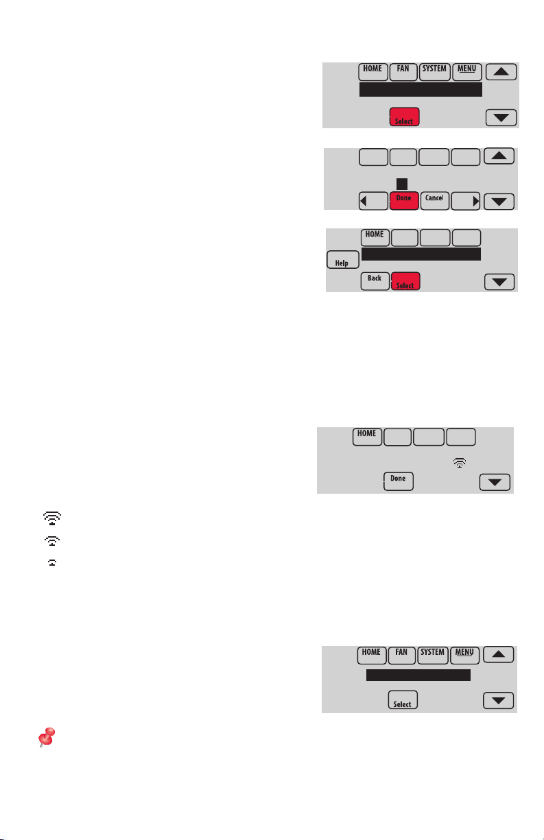
1 Touch Menu.
Installer Options
2 Select Installer Options.
3 Enter password (date code) and
touch Done. See “Finding the password” on
page 7 to find the date code.
4 Select Installer Setup or Installer Test.
5 Follow prompts on the screen to select
the desired setup options or to perform an
equipment test.
Checking signal strength
After you successfully connect to the Wi-Fi
network (see “Connecting to Wi-Fi” step 1.5),
the thermostat will display signal strength. The
signal strength symbols have the following
meanings:
Signal strength is 75%–100%
Signal strength is 50%–75%
Signal strength is 0%–50%
Enter password
0 0 0 0
Installer Setup
Installer Test
Wi-Fi Network:
YourNetwork
You can also check signal strength at any time after the thermostat is connected to the
Wi-Fi network by pressing MENU then Wi-Fi Setup.
Connecting to Wi-Fi later
1 Press MENU, then Wi-Fi Setup.
2 Follow the prompts on-screen (and in
“Connecting to Wi-Fi”) to select the Wi-Fi
network and enter the password.
NOTE: To view and set the Wi-Fi thermostat
remotely, the homeowner must have a Total
Connect Comfort account. See “Connecting
to Wi-Fi” step 2.
8
DoaIol Inrol Madorl
Wi-Fi Setup
Installer Options
Page 9
Unsuccessful connection
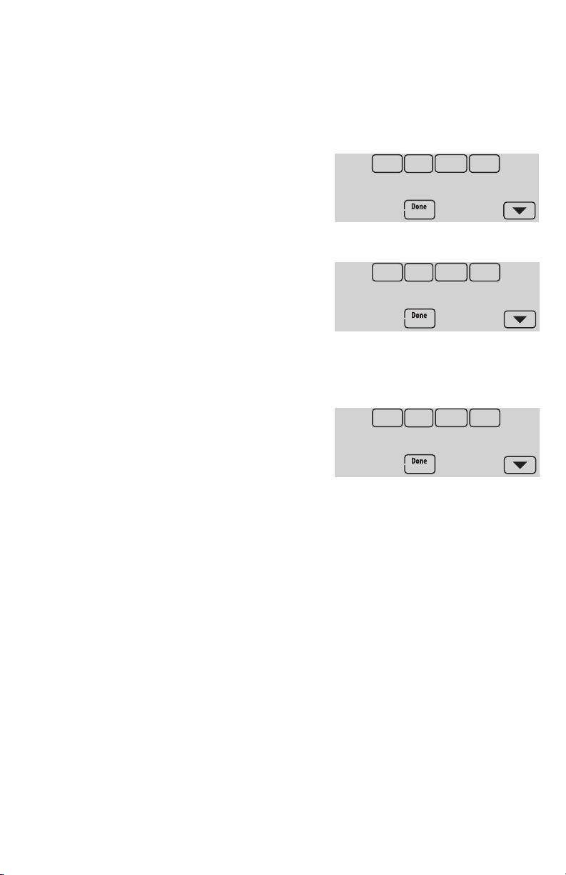
If you are unsuccessful in connecting the thermostat to the Wi-Fi network, you will
see a Connection Failed screen. Press the t button for other tips about this failed
connection. Here are three specific reasons the connection might be unsuccessful.
For all Connection Failed screens, pressing Done will return to the Menu screen.
Invalid Password
The password you entered is invalid. Check that
you have the right password and try again.
Press Back to return to “Connecting to Wi-Fi”
step 1.3 on page 6.
No IP Address
The thermostat was unable to obtain an IP
address from the router. Verify the router is
correctly set up to automatically assign IP
addresses. This connection can take several
minutes. If there is still no connection, remove
the thermostat from the wallplate for 10 seconds,
then snap it back into place.
No Internet Link
The thermostat connected to the Wi-Fi network
but was unable to establish a connection to the
internet. Check the router settings and try again.
Make sure the Ethernet cable is plugged into the
router and try rebooting the router if necessary.
Connection Failed
Invalid Password
Connection Failed
No IP Address
Connection Failed
No Internet Link
9
Page 10
Connecting to a hidden Wi-Fi network
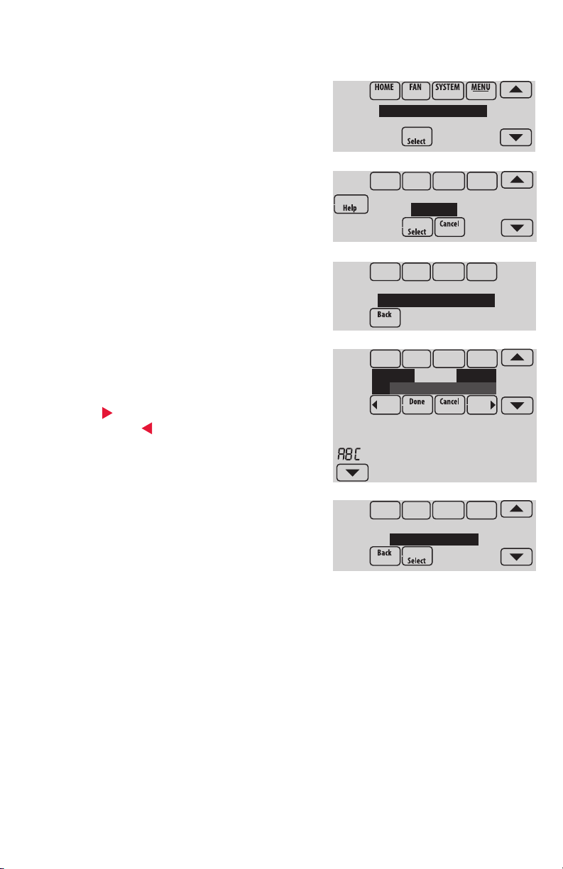
If the Wi-Fi network name is hidden and it doesn’t show up in the list in “Connecting to
Wi-Fi” follow these steps to connect to it.
1 Press MENU, then Wi-Fi Setup.
DoaIol Inrol Madorl
Wi-Fi Setup
Installer Options
2 Press Other, then press Select.
3 When prompted, press the screen to edit the
network name.
4 Enter the network name.
Press the s or t buttons to change the letter
or number.
Press the
button to move to the next
character, or the button to move to the
previous character.
Use the s or t buttons at the bottom to
change letter case.
Press Done when complete.
5 Select the appropriate network security setting,
then press Select.
6 Enter the Wi-Fi network password as shown in
“Connecting to Wi-Fi” step 1.4.
WirelessNetwork
Other...
Enter Network Name
Press Here to Edit
Delete Space
AC
SSID Security
Open Network
10
Page 11
Specifications and replacement parts
Operating Ambient Temperature
Thermostat: 32 to 120° F (0 to 48.9° C)
Operating Relative Humidity
Thermostat: 5% to 90% (non-condensing)
Physical Dimensions (height, width, depth)
Thermostat: 4-15/16 x 4-5/8 x 1-1/8 inches (126 mm x 118 mm x 29 mm)
Wi-Fi Communication
Supports 802.11 B/G/N home wireless router
Frequency: 2.4 Ghz
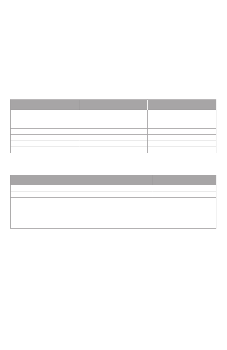
Electrical ratings
Terminal Voltage (50/60 Hz) Max. Current Rating
W - OB 18 to 30 VAC and 750 mVDC 1.00A
Y (cooling) 18 to 30 VAC 1.00A
G (fan) 18 to 30 VAC 0.50A
W2 - Aux (heating) 18 to 30 VAC 0.60A
Y2 (cooling) 18 to 30 VAC 0.60A
A-L/A (output) 18 to 30 VAC 1.00A
U1/U1 30 VAC max. 0.50A
Accessories and replacement parts
Accessories / Replacement Parts Part Number
Wired Outdoor Sensor 10k ohm NTC C7089U1006
Wired Wall-mount Indoor Sensor 10k ohm NTC C7189U1005
Wired Flush-mount Indoor Sensor 20k ohm NTC C7772A1004, C7772A1012
Wired Wall-mount Indoor Sensor 20k ohm NTC TR21
Wired Wall-mount Indoor Sensor 10k ohm NTC TR21-A
Cover Plate (covers marks left by old thermostats) THP2400A1019
Wire Saver Module THP9045A1023
11
Page 12
33-00065-01
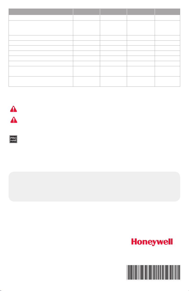
Model Numbering TH8321WF TH8321R TH8320R TH8110R
RedLINK™ or Wi-Fi
Stages
Residential or Commercial
Dual Powered - C Wire or Battery C Wire only
Onboard Humidity Sensor
Number of Universal Relays
Number of Universal Sensor Inputs
Economizer / TOD Output
Works with Optional Equipment
Interface Module*
Works with Optional TrueZONE
Wireless Adapter*
* The relay outputs and inputs on the thermostat do not function when used with an Equipment Interface Module or
the TrueZONE Wireless Adapter.
DISCONNECT POWER BEFORE INSTALLATION. Can cause electrical shock or equipment
damage.
MERCURY NOTICE: If this product is replacing a control that contains mercury in a sealed
tube, do not place the old control in the trash. Contact the Thermostat Recycling Corporation at
www.thermostat-recycle.org or 800-238-8192 for information on how and where to properly and
safely dispose of your old thermostat.
Must be installed by a trained, experience technician. Read these instructions carefully.
Failure to follow these instructions can damage the product or cause a hazardous condition.
Wi-Fi RedLINK™ RedLINK™ RedLINK™
3H/2C HP
2H/2C CONV
3H/2C HP
2H/2C CONV
3H/2C HP
2H/2C CONV
1H/1C HP
P P P P
P P P
P P
1 1 0 0
1 1 1 1
P P P
P P P
P P P
1H/1C
CONV
Need Help?
For assistance please visit http://customer.honeywell.com
or call toll-free: 1-855-733-5465
Automation and Control Systems
Honeywell International Inc.
1985 Douglas Drive North
Golden Valley, MN 55422
http://customer.honeywell.com
® U.S. Registered Trade mark.
© 2014 Honeywell Inter natio nal Inc .
33- 000 65— 01 M.S. 10-14
Printed i n U.S.A .
 Loading...