

Honeywell THP2400A1019 Installation Manual
69-2762EFS-02
THP2400A1019
Cover Plate Assembly
INSTALLATION GUIDE
APPLICATION
Use the THP2400A1019 cover plate assembly with the RedLINK™ VisionPRO® or Wi-Fi VisionPRO® thermostats.
Use the THP2400A1019 cover plate assembly to cover marks on the wall or to mount the thermostat to a 2 in. x
4 in. electrical box.
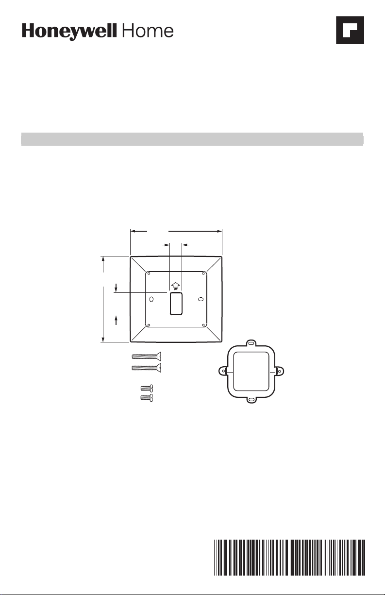
The THP2400A1019 cover plate assembly contains one cover plate, one bracket, two #6-32 x 5/8 flat head
screws and two #6-32 x 1/4 pan head screws. See Fig. 1.
6-5/32
5-3/4
(146)
1-1/2
(38)
(156)
25/32
(20)
TWO #6-32 X 5/8 FLAT HEAD SCREWS
TWO #6-32 X 1/4 PAN HEAD SCREWS
Fig. 1. THP2400A1019 cover plate assembly.
LEVEL
BRACKET
LEVEL
M34258
INSTALLATION
When Installing this Product…
1. Read these instructions carefully. Failure to follow them could damage the product or cause a hazardous
condition.
2. Check ratings given in the instructions and on the product to make sure the product is suitable for your
application.
3. Installer must be a trained, experienced service technician.
4. After installation is complete, check out product operation as provided in these instructions.
THP2400A1019 COVER PLATE ASSEMBLY
CAUTION
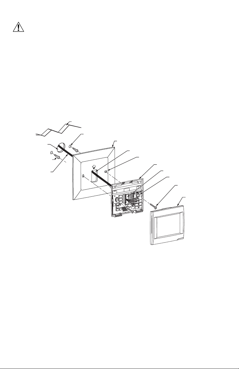
WALL OPENING
WALL ANCHORS (2)
(PROVIDED WITH
THERMOSTAT)
DRILLED HOLES (2)
WALL
MOUNTING SCREWS (2)
(PROVIDED WITH
THERMOSTAT)
M34259
WIRE
WIRE HOLE
COVER PLATE
MOUNTING HOLES (2)
THERMOSTAT
WIRE HOLE
WALL PLATE
MOUNTING HOLES (2)
Electrical Hazard.
Can cause electrical shock or equipment damage.
Disconnect power before beginning installation.
Mount Cover Plate
Mount Cover Plate Directly to Wall (See Fig. 2)
1. Pull the wires through the wire hole on the cover plate and wall plate.
2. Position the cover plate and wall plate on the wall with the arrows pointing up. Level the wall plate for
appearance only.
3. Use a pencil to mark the mounting holes for your thermostat.
4. Remove the cover plate and wall plate from the wall and drill two 3/16-in. holes in the wall (if drywall) as
marked. For firmer material such as plaster, drill two 7/32-in. holes. Tap the wall anchors (provided with
the thermostat) into the holes, until the anchor collar touches the wall.
5. Pull the wires through the wire hole on the cover plate and wall plate. Position the cover plate and wall
plate on the wall anchors.
6. Insert the mounting screws (provided with the thermostat) into the wall anchors. Check leveling, if desired,
and tighten the mounting screws.
Fig. 2. Mount cover plate, wall plate and thermostat directly to wall.
69-2762EFS—02 2
THP2400A1019 COVER PLATE ASSEMBLY
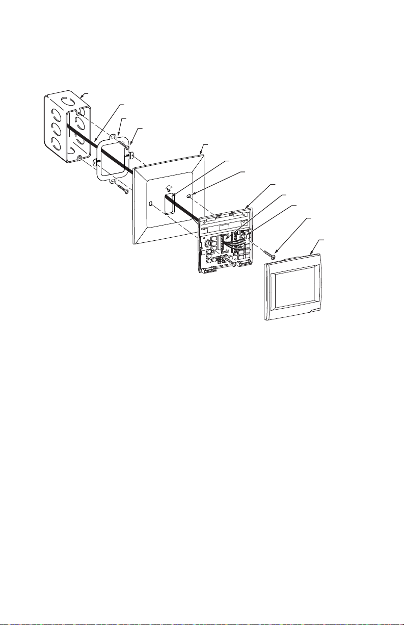
Mount Cover Plate to a Vertical 2 in. X 4 in. Electrical Box (See Fig. 3)
1. Position the bracket on the electrical box. Insert two #6-32 X 5/8 flat head screws. Check leveling, if
desired, and tighten the flat head screws.
2. Pull the wires through the wire hole on the cover plate and wall plate. Position the cover plate and wall
plate on the bracket with the arrows pointing up.
3. Insert two #6-32 X 1/4 pan head screws and tighten.
ELECTRICAL BOX
WIRE
BRACKET
#6-32 X 5/8 FLAT
HEAD SCREWS (2)
COVER PLATE
WIRE HOLE
MOUNTING HOLES (2)
WALL PLATE
WIRE HOLE
MOUNTING HOLES (2)
#6-32 X 1/4 PAN
HEAD SCREWS (2)
THERMOSTAT
M34260
Fig. 3. Mount bracket, cover plate, wall plate and thermostat to a vertical 2 in. X 4 in. electrical box.
3 69-2762EFS—02
THP2400A1019 COVER PLATE ASSEMBLY
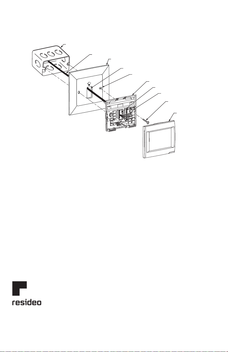
#6-32 X 5/8 FLAT
HEAD SCREWS (2)
M34261
ELECTRICAL BOX
WIRE
WIRE HOLE
COVER PLATE
MOUNTING HOLES (2)
THERMOSTAT
WIRE HOLE
WALL PLATE
MOUNTING HOLES (2)
Mount Cover Plate to a Horizontal 2 in. X 4 in. Electrical Box (See Fig 4)
1. Pull the wires through the wire hole on the cover plate and wall plate. Position the cover plate and wall
plate on the electrical box with the arrows pointing up.
2. Insert two #6-32 X 5/8 flat head screws. Check leveling, if desired, and tighten the flat head screws.
Fig. 4. Mount cover plate, wall plate and thermostat to a horizontal 2 in. X 4 in. electrical box.
Resideo Technologies, Inc.
1985 Douglas Drive North , Golden Valley, MN 55422
www.resideo.com
© 2020 Resideo Technologies, Inc. All rights reserved.
The Honeywell Home trademark is used under license from Honeywell International, Inc. This product is manufactu red by Resideo Technologies, Inc. and its affiliates.
Tous droits réservés. La marque de commerce Honey well Home est utilisée avec l’autorisation d’Honey well International, Inc.
Ce produit est fabriqué par Resideo Technologies, Inc. et ses sociétés affiliées.
Todos los derechos reservados.
La marca comercial Honeywell Home se utiliza bajo licencia de H oneywell International, Inc. Este producto es fabricado por Re sideo Technologies, Inc. y sus afiliados.
1-800-468-1502
69-2762EFS—02 M.S. Rev. 01-20 | Printed in United States
 Loading...