

Honeywell Thor VX8, VX8 User Manual

Thor™ VX8
Vehicle-Mount Computer
Microsoft®Windows®Embedded Standard Operating System
Microsoft®Windows®7 Professional Operating System
Microsoft®Windows®XP®Professional Operating System
Reference Guide

Disclaimer
Honeywell International Inc. (“HII”) reserves the right to make changes in specifications and other information contained in this
document without prior notice, and the reader should in all cases consult HII to determine whether any such changes have
been made. The information in this publication does not represent a commitment on the part of HII.
HII shall not be liable for technical or editorial errors or omissions contained herein; nor for incidental or consequential damages
resulting from the furnishing, performance, or use of this material.
This document contains proprietary information that is protected by copyright. All rights are reserved. No part of this document
may be photocopied, reproduced, or translated into another language without the prior written consent of HII.
© 2009-2012 Honeywell International Inc. All rights reserved.
Web Address: www.honeywellaidc.com
RFTerm is a trademark or registered trademark of EMS Technologies, Inc. in the United States and/or other countries.
Microsoft®Windows, ActiveSync®, MSN, Outlook®, Windows Mobile®, the Windows logo, and Windows Media are
registered trademarks or trademarks of Microsoft Corporation.
Intel®, Atom™, Core™, Celeron®and Pentium®are trademarks or registered trademarks of Intel Corporation or its
subsidiaries in the United States and other countries.
Summit Data Communications, the Laird Technologies Logo, the Summit logo, and "Connected. No Matter What" are
trademarks of Laird Technologies, Inc.
Atheros®and the Atheros logo are registered trademarks of Atheros Communications, Inc.
Broadcom®and the Broadcom logo are registered trademarks of Broadcom Corporation.
The Bluetooth®word mark and logos are owned by the Bluetooth SIG, Inc.
Symbol®is a registered trademark of Symbol Technologies. MOTOROLA, MOTO, MOTOROLA SOLUTIONS and the
Stylized M Logo are trademarks or registered trademarks of Motorola Trademark Holdings, LLC and are used under license.
RAM®and RAM Mount™ are both trademarks of National Products Inc., 1205 S. Orr Street, Seattle, WA 98108.
Freefloat, Freefloat Wlinq and Freefloat Access*One are trademarks of Freefloat, Mölndalsvägen 30B, SE-412 63Gothenburg,
Sweden.
OneClick Internet is WebToGo’s patented connection manager customized for Honeywell mobile devices. OneClick Internet
documentation is copyright 2010 by WebToGo and modified by Honeywell with WebToGo’s express permission.
Verizon®is a registered trademark of Verizon Trademark Services LLC.
T-MOBILE®is a registered trademark of Deutsche Telekom AG.
AT&T®is a registered trademark of AT&T Intellectual Property.
Option®and GlobeTrotter®are registered trademarks of Option NV.
Acrobat®Reader © 2012with express permission from Adobe Systems Incorporated.
Other product names or marks mentioned in this document may be trademarks or registered trademarks of other companies
and are the property of their respective owners.
Patents
For patent information, please refer to www.honeywellaidc.com/patents.
Limited Warranty
Refer to www.honeywellaidc.com/warranty_information for your product’s warranty information.

Table of Contents
Chapter 1: Introduction 1-1
Overview 1-1
Microsoft Windows License Agreement (First Boot) 1-1
Quick Start 1-2
Components 1-3
Under Service Lid 1-3
Connector Panel 1-4
Buttons and LEDs 1-5
LED Indications 1-6
Power LED 1-6
UPS Mode LED 1-6
Hard Drive LED 1-6
Data Entry 1-7
Keyboard Data Entry 1-7
Bar Code Data Entry 1-7
Touch Screen Entry 1-7
Soft Keyboard Entry 1-8
Chapter 2: Hardware 2-1
Hardware Configuration 2-1
Power Input 2-1
Uninterruptible Power Supply 2-1
Backup Battery 2-1
PCMCIA Slot 2-1
Power Management 2-1
Physical Controls 2-2
Power Button 2-2
Display Brightness Buttons 2-3
External Connectors 2-4
Serial Connector – COM1 2-5
Pinout 2-5
Serial Connector – COM2 2-6
Pinout 2-6
PS/2 Keyboard Connector 2-7
Pinout 2-7
PS/2 Mouse Connector 2-8
Pinout 2-8
RJ45 Connector 2-9
i

Pinout 2-9
Multipurpose Connector 2-10
Pinout 2-10
Multipurpose Dongle Cables 2-11
D15 Female Connector 2-12
Pinout 2-12
USB Connector 2-13
Pinout 2-13
Serial Connector - COM4 2-14
Pinout 2-14
Audio and Microphone Connectors 2-15
Antenna Connectors 2-15
Power Supply Connector 2-16
Pinout 2-16
Keyboards 2-17
95-key Keyboard 2-17
60-key Keyboard 2-18
95-key QWERTY Keyboard with Pointing Device 2-19
Key Maps 2-19
NumLock 2-19
CapsLock and Scroll Lock 2-19
Keyboard Backlight 2-20
60-key QWERTY Keyboard 2-21
Key Maps 2-21
Unused Key Functions 2-21
NumLock 2-21
Keyboard Backlight 2-22
Control Keys 2-22
Keyboard LEDs 2-23
CAPS LED 2-23
Secondary Keys LED 2-24
IBM 3270 Keypad Overlay 2-25
IBM 5250 Keypad Overlay 2-25
General Windows Keyboard Shortcuts 2-26
PS/2 Keyboard/Mouse 2-27
Virtual Keyboard 2-27
Display 2-29
Cleaning the Display 2-29
Touch Screen 2-29
PCMCIA Slot (Optional) 2-30
ii

Install PCMCIA Cards 2-30
PCMCIA Pinout 2-31
Power Supply 2-32
Vehicle DC Connection 2-33
Screen Blanking 2-35
Uninterruptible Power Supply Battery Pack 2-36
External Power Supply 2-36
CMOS Battery 2-36
Hardware Problems 2-37
Power Source 2-37
Keyboard 1-7
Display / Touch Screen 2-38
Hard Disk Drive 2-38
Memory Conflicts 2-38
Optional Devices 2-39
Chapter 3: Software 3-1
Introduction 3-1
Operating System 3-1
BIOS Setup 3-2
Accessing the BIOS Setup 3-3
AMI BIOS 3-3
Phoenix BIOS 3-3
Identifying Drives in the Thor VX8 3-3
AMI BIOS 3-3
Phoenix BIOS 3-3
Integrated Devices 3-4
AMI BIOS 3-4
Phoenix BIOS 3-4
Boot Priority 3-5
AMI BIOS 3-5
Phoenix BIOS 3-5
PXE - Pre Boot Execution 3-5
AMI BIOS 3-5
Phoenix BIOS 3-5
Exit BIOS Configuration 3-6
AMI BIOS 3-6
Phoenix BIOS 3-6
VMT Keyboard Backlighting 3-7
Microsoft Windows Setup and Configuration 3-8
iii

Microsoft Windows License Agreement (First Boot) 3-8
Drive C Directory Structure 3-8
Software Loaded on Drive C 3-9
Thor VX8 Configuration Options 3-10
Date and Time 3-10
Power Management 3-10
Speaker Volume 3-10
Connect Bluetooth Devices 3-10
Restart/Shutdown 3-11
Soft Keyboard 3-11
Calibrate Touch Screen 3-11
Touch Screen 3-12
Calibrating the Touch Screen 3-12
Disabling the Touch Screen 3-12
Network Configuration 3-12
802.11 Wireless Radios 3-12
Ethernet Connector 3-12
WWAN 3-12
Bluetooth 3-12
VMT Manager 3-13
Main Tab 3-13
General Settings Tab 3-14
UPS Tab 3-16
Display Backlight Tab 3-17
Advanced Tab 3-19
Wedge 3-20
Configuration 3-20
Loading an Operating System on the Thor VX8 3-22
The Thor VX8 Recovery DVD 3-23
DVD Part numbers 3-23
Thor VX8 Recovery DVD 3-23
Launching the RS2 Wizard 3-23
Using the RS2 Wizard 3-24
The Thor VX8 Drivers CD-ROM 3-25
Startup Problems 3-26
Bypassing Microsoft Windows Startup 3-26
Verifying Boot Order 3-26
Setting System Time and Date 3-27
Chapter 4: Wireless Network Configuration 4-1
iv

Introduction 4-1
Summit Wireless Network Configuration 4-2
Important Notes 4-2
Summit Client Utility 4-3
Help 4-3
Summit Tray Icon 4-4
Wireless Zero Config Utility 4-5
How To: Use the Wireless Zero Config Utility 4-5
How to: Switch Control to SCU 4-5
Main Tab 4-6
Admin Login 4-7
Profile Tab 4-8
Buttons 4-9
Profile Parameters 4-10
Status Tab 4-12
Diags Tab 4-13
Global Tab 4-14
Custom Parameter Option 4-15
Global Parameters 4-16
Logon Options 4-20
Single Signon 4-21
Pre-Logon Connection 4-21
Sign-On vs. Stored Credentials 4-22
How to: Use Stored Credentials 4-22
How to: Use Sign On Screen 4-23
How to: Use Windows Username and Password 4-23
Windows Certificate Store vs. Certs Path 4-24
User Certificates 4-24
Root CA Certificates 4-24
How To: Use the Certs Path 4-24
How To: Use Windows Certificate Store 4-24
Configuring the Profile 4-26
No Security 4-27
WEP 4-28
LEAP 4-30
PEAP/MSCHAP 4-32
PEAP/GTC 4-35
WPA/LEAP 4-38
EAP-FAST 4-40
EAP-TLS 4-42
v

WPA PSK 4-45
Certificates 4-46
Generating a Root CA Certificate 4-47
Installing a Root CA Certificate 4-51
Generating a User Certificate 4-53
Exporting a User Certificate 4-56
Installing a User Certificate 4-58
Atheros Client Utility - 802.11a/b/g Radio 4-60
Wireless Zero Config 4-60
Using the ACU 4-61
No Security 4-62
WEP 4-63
LEAP 4-65
WPA-PSK 4-67
PEAP/MS-CHAP 4-68
PEAP-GTC 4-70
EAP-TLS 4-72
WPA LEAP 4-74
EAP-FAST 4-76
Broadcom Wireless Utility - 802.11b/g Radio 4-79
Wireless Zero Config 4-79
Using the BWU 4-79
No Security 4-80
WEP 4-81
LEAP 4-82
WPA-PSK 4-83
PEAP/MS-CHAP 4-84
PEAP-GTC 4-85
EAP-TLS 4-86
WPA LEAP 4-88
EAP-FAST 4-89
Certificates 4-90
Bluetooth 4-92
8650 Bluetooth Ring Scanner/Imager 4-92
Devices Tab 4-92
Options Tab 4-94
COM Ports Tab 4-95
Hardware Tab 4-96
SIM card installation 4-97
Requirements 4-97
vi

Installation 4-97
Option GlobeTrotter Connect 4-99
SIM Card PIN 4-99
Using Option GlobeTrotter Connect 4-99
OneClick Internet 4-101
Preparing for Initial Use on the Thor VX8 4-101
Install SIM Card 4-101
Load Firmware 4-101
Activation 4-101
Using OneClick Internet 4-104
Connection Management 4-104
Menu Buttons 4-105
Radio Button 4-105
StatisticsButton 4-105
Update Button 4-105
Help Button 4-105
Settings Button 4-106
Profile Tab 4-107
Buttons 4-108
Parameters 4-108
Network Tab 4-109
Network with SIM Card 4-109
CDMA Network 4-111
History Tab 4-112
PIN Tab 4-112
Activate/Deactivate PIN 4-112
Change PIN 4-113
Info Tab 4-114
Firmware Tab 4-115
Activation on CDMA 4-116
General Tab 4-117
Application Tab 4-118
Application Buttons 4-119
SMS 4-119
Web Browser 4-119
Email 4-119
GPS 4-119
About 4-120
System Requirements 4-120
Supported Languages 4-120
vii

Installing or Upgrading OneClick Internet 4-120
Installation 4-121
OneClick Internet Connection Manager 4-124
Connection Management 4-124
Information Buttons 4-125
Chapter 5: Key Maps 5-1
95-key Keypad with Pointing Device 5-1
Key Map 101-Key Equivalencies 5-1
60-key Standard Keypad 5-2
60 Key KeyMap 101-Key Equivalencies 5-2
IBM Terminal Emulation 5-7
IBM 3270 Keypad Overlay 5-7
IBM 5250 Keypad Overlay 5-8
Chapter 6: Technical Specifications 6-1
Physical Specifications 6-1
Environmental Specifications 6-2
Display Specifications 6-2
Operating System 6-2
Radio Options 6-3
Chapter 7: Technical Assistance 7-1
viii
Chapter 1: Introduction
Overview
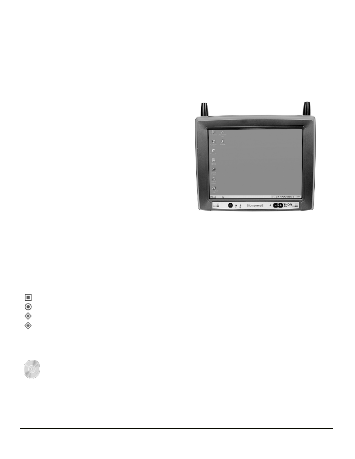
The Thor VX8 Vehicle-Mount Computer (VMT) is a rugged,
vehicle-mounted, PC (Personal Computer) equipped with a
Microsoft®Windows®operating system. The Thor VX8 is
capable of wireless data communications from a fork-lift truck or
any properly configured vehicle. The unit uses a PCMCIA radio
(spread spectrum 2.4GHz) for wireless data communications.
The Thor VX8 is a tablet-style computer and features a color
display. The touch-screen display supports graphic features and
Microsoft Windows icons that the Windows operating system
supports. An illuminated keyboard is available to facilitate use in
dimly lit areas.
The Thor VX8 provides the power and functionality of a desktop
computer in a vehicle-mounted unit, with a wide range of options.
For details on available RAM Mount™ options see the Thor VX8 Vehicle Mounting Reference Guide.
The Thor VX8 is available with the following operating systems:
l Windows
l Windows
l Windows
l Windows
The Thor VX8 can support only one operating system at a time. Information in this guide includes instruction for all operating
systems. Differences are highlighted as follows:
®
7 Professional
®
XP Professional
®
Embedded Standard
®
XP Embedded
Windows® 7 Professional
Windows® Embedded Standard
Windows® XP Embedded
Windows® XP Professional
Microsoft Windows License Agreement (First Boot)
If your Thor VX8 is shipped with a Microsoft Windows operating system pre-installed, it may be necessary to
complete the Windows licensing/registration screens when starting the Thor VX8 for the first time. To complete this
information, you may need the Microsoft Windows software/product key that was included with the Thor VX8.
Please refer to Microsoft Windows License Agreement (First Boot) for instruction.
1-1

Quick Start
This section’s instructions are based on the assumption that your new system is pre-configured and requires only accessory
installation (e.g. antenna, external keyboard and/or bar code scanner) and a power source.
In general, the sequence of events to prepare the Thor VX8 for use is:
1. Install Vehicle Mounting Bracket (and keyboard mounting bracket) on vehicle.
2. Secure Thor VX8 in Mounting Bracket Assembly.
3. Connect power cable to the Thor VX8. Route the power cable to a DC/DC converter then to the vehicle battery.
4. An optional screen blanking box may also be connected to the Thor VX8.
5. Connect accessories to Thor VX8, e.g. scanner, keyboard.
6. Secure all cables to the Thor VX8 with the Strain Relief Cable Clamps.
7. Turn the Thor VX8 on.
The Thor VX8 and its keyboard should be mounted in an area in the vehicle where it:
l Does not obstruct the vehicle driver’s vision or safe vehicle operation.
l Can be easily accessed by anyone seated in the driver’s seat.
1-2
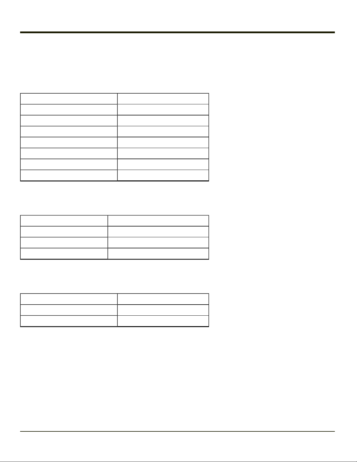
Components
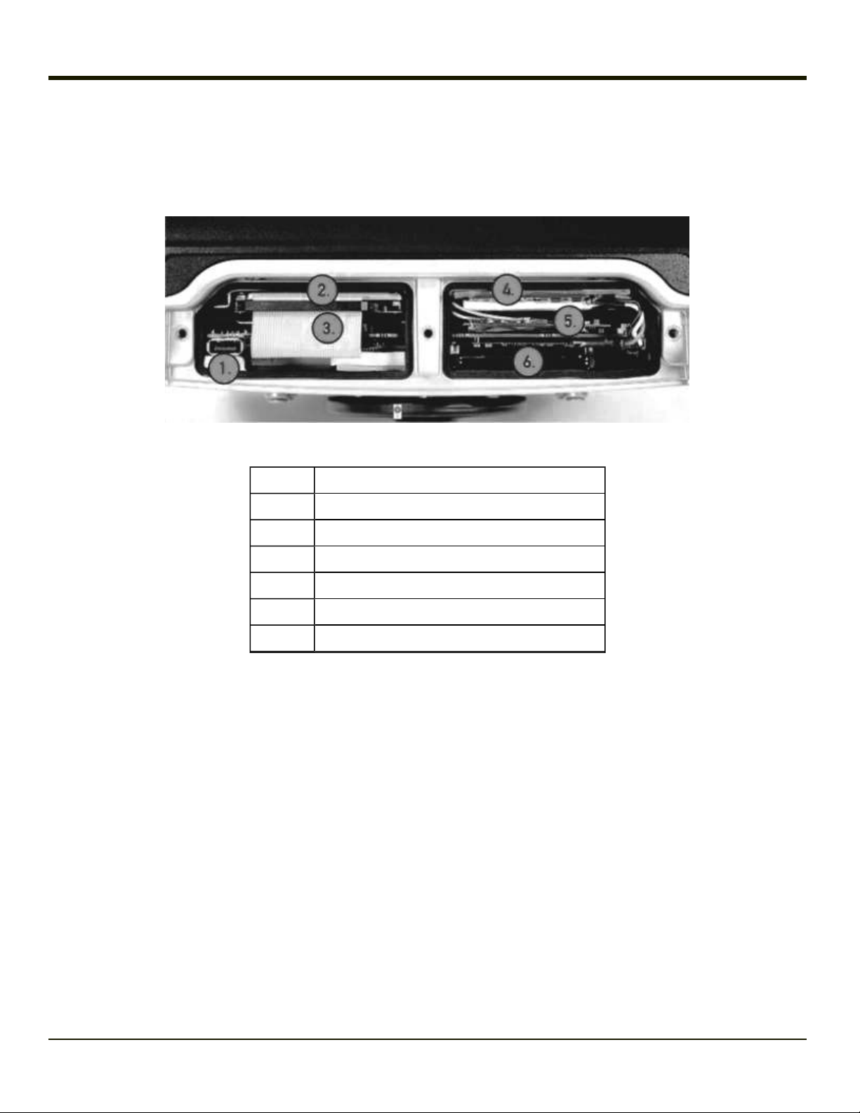
Under Service Lid
The service lid has been removed to show components.
Position Function
1 USB 2.0
2 Hard drive
3 CompactFlash slot, optional (behind HD cable)
4 Battery/UPS
5 Mini PCI slot
6 PC Card slot (option)
1-3
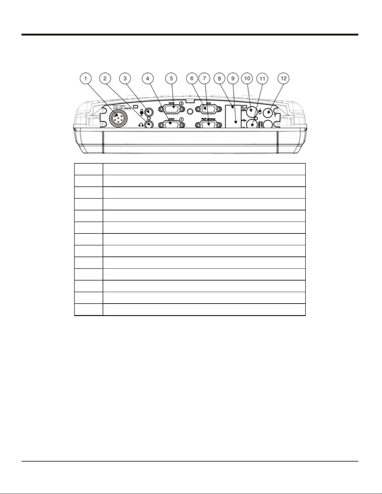
Connector Panel
Position Function
1 Power Supply Connector (12V DC 50W)
2 Mic. in
3 Audio out
4 COM1 Connector
5 COM2 Connector
6 VGA (external monitor) Connector
7 Multipurpose Connector (provides USB, COM4 or both with optional cable)
8 RJ-45 Ethernet 10/100 Connector
9 2x USB 2.0 Ports
10 PS/2 Mouse port
11 PS/2 Keyboard Port
12 Bluetooth Antenna Connector
1-4
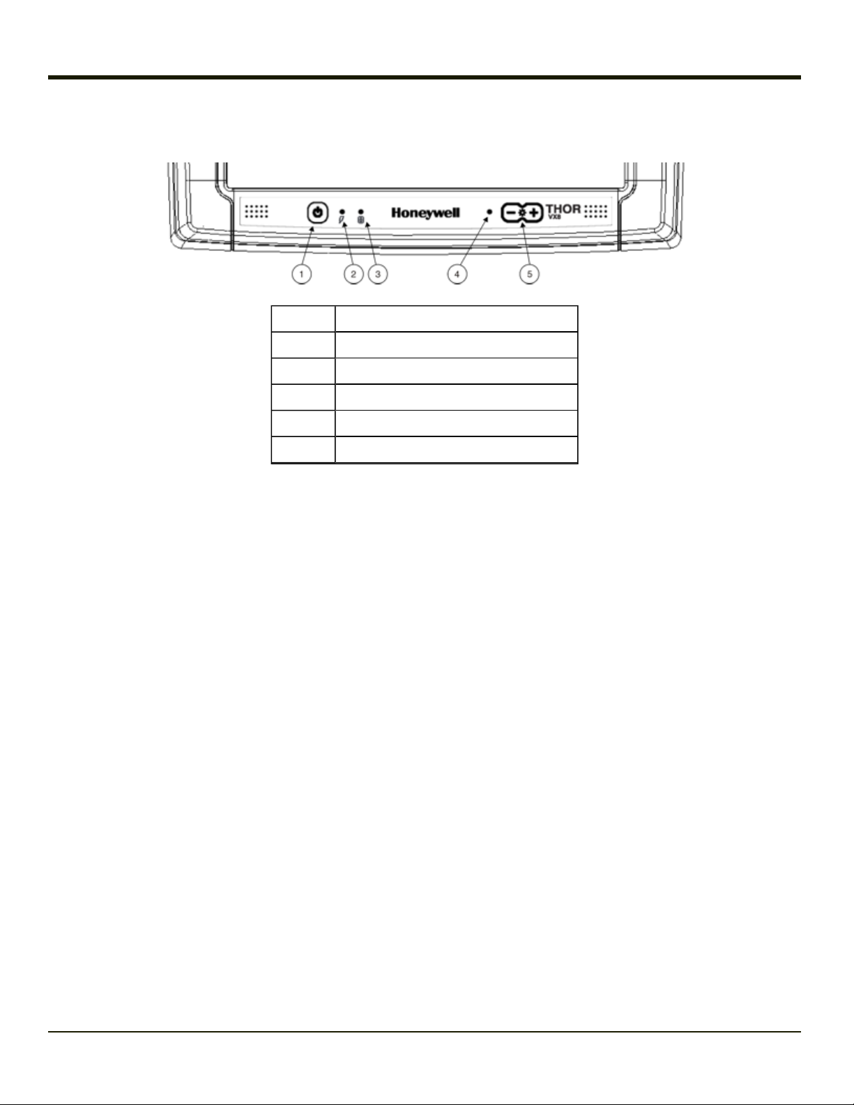
Buttons and LEDs
Position Function
1 Power Button (includes Power LED)
2 UPS Mode LED
3 Hard Drive LED
4 Light Sensor
5 Screen Brightness Adjustment Buttons
1-5
LED Indications
Power LED
The Power LED is incorporated into the power button.
Function Power LED
Off and not powered Off (no light)
Off but powered Green flash very slow
Operating normally Green on
Suspend Green flashing slow
Black-out Screen Green flashing fast
Over voltage shutdown Red on
Over temperature Red flashing
UPS Mode LED
The UPS Mode LED is located to the right of the power button.
Function UPS Mode LED
UPS battery powered Green flashing fast
UPS battery charging Green on or flashing slow
UPS battery charged Off (no light)
Hard Drive LED
The Hard Drive LED is located to the right of the UPS Mode LED.
Function Hard Drive LED
Hard drive activity Green flashing
No activity Off (dark)
1-6

Data Entry
You can enter data into the Thor VX8 through several different methods. A tethered scanner connected to the COM1 serial port
or a Bluetooth scanner provides bar code data entry, the serial ports are used to input/output data, keyboards provide manual
entry and the touch screen also provides manual entry (simulating a desktop PC’s mouse).
Keyboard Data Entry
Refer to Key Maps for 101-key keyboard equivalent keypresses.
The keyboard is used to manually input data that is not collected otherwise. Almost any function that a full sized computer
keyboard can provide is duplicated on the VMT keyboard but it may take a few more keystrokes to accomplish a keyed task.
When using the 60-key keyboard almost every key has two or three different functions. The primary alpha or numeric character
is printed on the key.
For example, when the 2ndkey is selected pressing the desired second-function key produces the 2ndcharacter i.e. 2nd+ F1
toggles the CAPS Lock function. The specific 2ndcharacter is printed above the corresponding key.
Bar Code Data Entry
The Thor VX8 supports an accessory bar code label reading device. Keyboard data entries can be mixed with bar code data
entries. Any scanner that decodes the bar code internally and outputs an RS-232 data stream may be used. COM port 1 is
designed to be used with a hand held tethered bar code scanner. Also, a Bluetooth bar code scanner can be used to enter bar
code data into the Thor VX8.
COM1 must be set to +5V on pin 9 when using a tethered serial scanner. See VMT Manager.
Touch Screen Entry
Note: The touch screen should be calibrated before initial use. See Touch Screen Calibration.
Note: Always use the point of the stylus for tapping or making strokes on the display. Never use an actual pen, pencil or
sharp object to write on the touch screen.
The touch screen input performs the same function as the mouse that is used to point to and click elements on a desk top
computer. A stylus is used in the same manner as a mouse – single-tap or double-tap to select menu options, drag the stylus
across text to select, hold the stylus down to activate slider bars, etcetera. Right-click is generated by tapping the mouse icon
in the system tray. After tapping, the mouse icon highlights the right button of the icon in red. The next touch screen tap is
treated as a right-click. The mouse icon then returns to the left button highlighted in red so subsequent taps are treated as left
clicks.
Hold the stylus as if it were a pen or pencil. Touch an element on the screen with the tip of the stylus then remove the stylus
from the screen. The touch screen responds to an actuation force (touch) of up to 4 oz. of pressure.
The touch screen can be used in conjunction with the keyboard and scanner.
l Touch the stylus to the field of the data entry form to receive the next data feed.
l The cursor begins to flash in the field.
l The unit is ready to accept data from either the keyboard, integrated scanner or a device connected to a serial port.
Note: The touch screen may be disabled. Please refer to Disabling the Touch Screen.
1-7

Soft Keyboard Entry
The optional software keyboard provides a virtual keyboard on the touch screen. The soft keyboard is orderable in several
configurations.
Note: When the virtual keyboard is displayed, the physical keyboard is still active, if attached. Therefore it is possible to
input data from both keyboards.
1-8

Chapter 2: Hardware
Hardware Configuration
The Thor VX8 is available in many configurations. Please refer to Technical Specifications for available options.
Note: Using the VMT Manager, Pin 9 of COM1 may be configured to provide 5 volts DC to power a bar code scanner or RI
for serial transfer.
Power Input
Vehicle power input for the Thor VX8 is determined by the DC/DC power supply selected. The DC/DC power supply accepts
input in the stated range and provides a conditioned 12V DC output for the Thor VX8.
If DC power is not available – for example, in an office environment – an optional external Universal Input Power Supply can be
used to convert AC wall power to an appropriate DC level. See Power Supply.
Uninterruptible Power Supply
A DC uninterruptible power supply (UPS) battery is included to maintain power to the Thor VX8 for a minimum of 15 minutes
when vehicle power is not available (such as when a vehicle battery is being swapped). The UPS is configured via the VMT
Manager.
Backup Battery
The Thor VX8 has a permanent lithium battery installed to maintain time, date and BIOS setup information. The backup battery
is not user serviceable and should last five years with normal use before it requires replacement.
Note: This battery should only be changed by authorized service personnel.
PCMCIA Slot
Microsoft Windows Plug and Play operating system controls the PCMCIA cards. These cards are hot swappable per the
CardBus/PCMCIA specifications. PCMCIAslots are optional.
Power Management
The Thor VX8 uses Microsoft Windows Power Management. The Thor VX8 has two operating modes: Normal and Standby.
In Normal operating mode all systems are powered up and the video display is on. The RS-232 ports, any installed PCMCIA
cards are active. However, Microsoft Windows also allows the display and hard disks to be shut down in normal mode to
conserve energy.
The Standby mode shuts down many devices such as the display and hard drives. For complete details on the standby mode,
please refer to the Microsoft Help &Support (Start > Help and Support).
2-1
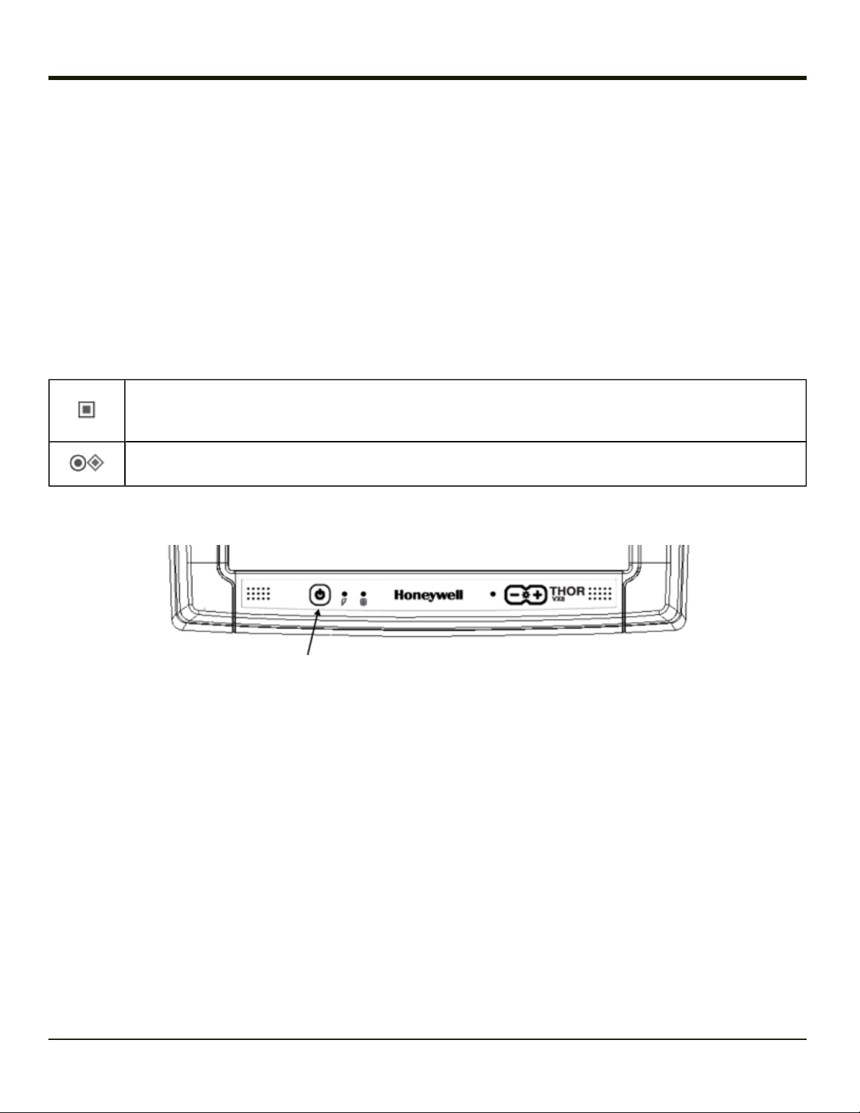
Physical Controls
Power Button
The power (on/off) button is a push button switch located on the front of the Thor VX8. The switch is a momentary switch. If the
Thor VX8 is Off, pressing the power switch turns the Thor VX8 On. If the Thor VX8 is On, Windows determines the results of a
power button press. For example, the Thor VX8 may be configured to:
l Shut down
l Hibernate
l Ignore the power button press
l Ask user to choose.
Power button behavior is configured by selecting:
Start > Control Panel > Power Options > Choose what the Power buttons do (Classic view)
Start > Control Panel > Hardware and Sound > Power Options > Choose what the Power buttons do (Cat-
egory view)
Start > Control Panel > Power Options > Advanced (Classic view)
Start > Control Panel > Performance and Maintenance > Power Options > Advanced (Category view)
Pressing and holding the power switch for several seconds forces a shutdown.
Note: Always turn the computer off prior to removing power cables.
The Thor VX8 is designed for a controlled shutdown when using the power button. A controlled shutdown first closes any open
programs, and then shuts down the Windows operating system. DO NOT remove power from the Thor VX8 without shutting
down the Thor VX8.
The Thor VX8 shutdown may be initiated in any of the following ways:
l Selecting the Shut Down option from the Windows Start Menu.
l Selecting the Shut Down option from the Windows Task Manager. The Windows Task Manager is displayed by
pressing Ctrl-Alt-Del.
l Momentarily pressing and releasing the power button. The Thor VX8 behavior when the power button is pressed can be
configured in the Windows Control Panel.
l Pressing and holding the power button for approximately five seconds. Any open programs and the Windows operating
system are shut down before power off. Note that this option must be used to shut down when the operating system is
not responding.
l The VMT Manager can be configured so that an extended touch on the touch screen initiates the shut down process.
For more information on the Windows shutdown process, please refer to Help and Support on the Windows Start menu or
commercially available Windows guides.
2-2
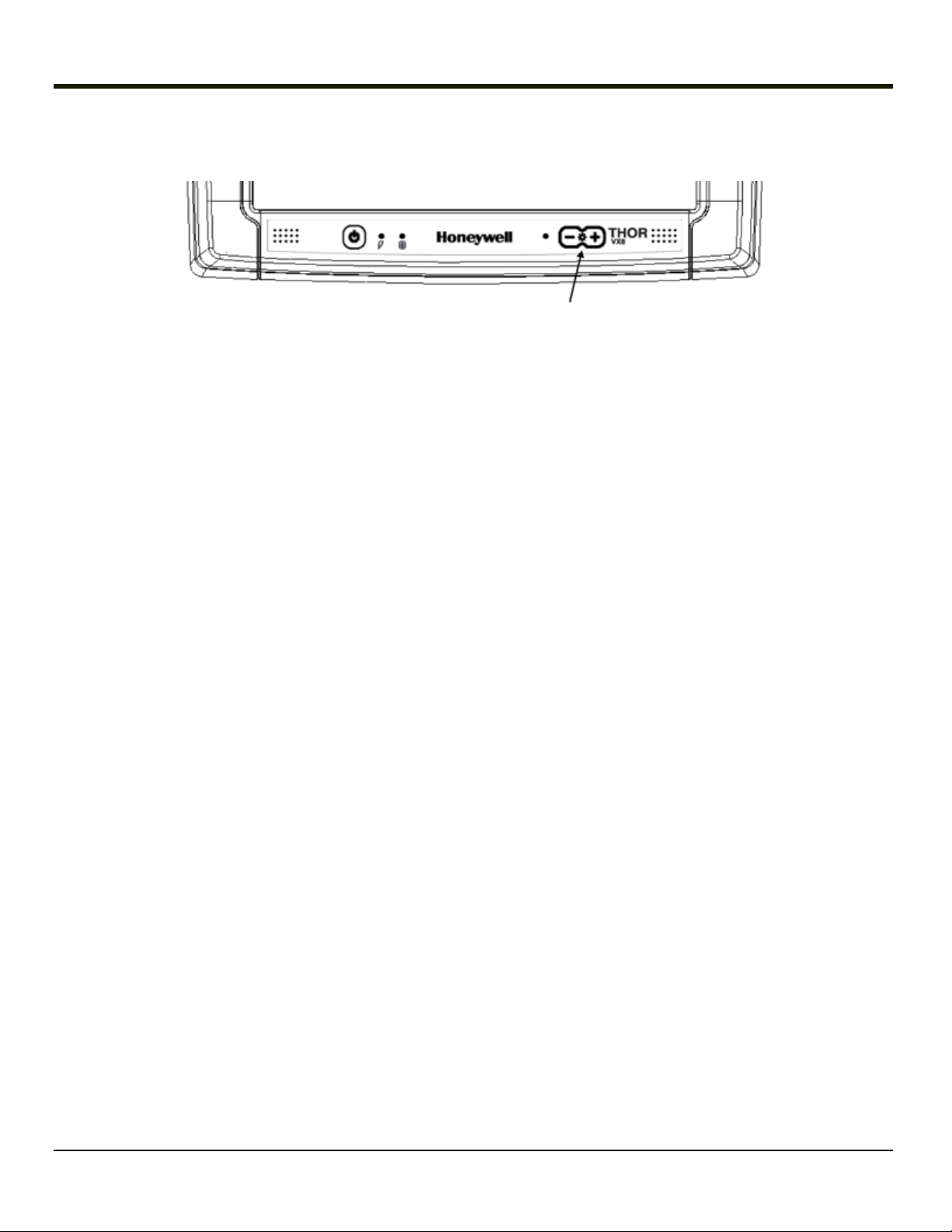
Display Brightness Buttons
Screen brightness is adjusted using the buttons (+) or (-) on the front of the Thor VX8.
The screen’s background lighting can be turned off by holding both buttons simultaneously.
Background lighting is restored by pushing one of the buttons or by touching the screen
The ambient-light autosensor is located on the front, to the left of the brightness controls.
Configuration of the ambient light control is handled via the VMT Manager option in the Control Panel.
2-3

External Connectors
Most external connectors for the Thor VX8 are located on the bottom of the unit.
l PS/2 connectors for Keyboard and Mouse.
l COM 1 connects to a serial bar code scanner cable.
l COM 2 connects to a serial printer or PC with the appropriate cables.
l The USB connectors are a standard USB type A host connector.
l The Ethernet connector is a standard RJ45 10/100 Ethernet connector.
l The multipurpose connector is a D15 connector that can provide a USB port, D9 serial RS-232 (COM4) port or both
depending on the accessory cable attached to the connector.
l Audio connector is a 3.5 mm jack for audio out, i.e. a headset.
l Microphone connector is a 3.5mm jack for audio in, i.e. a microphone.
l External Bluetooth antenna connector.
Note: Pin 9 of the COM 1 can be switched between +5V and RI to change between a bar code scanner and a serial port
printer or PC cable. See VMT Manager.
Other external connectors are located as follows:
l 802.11 antenna connectors are located on the top of the Thor VX8. One of these connectors may also be used by the
WWAN radio.
2-4
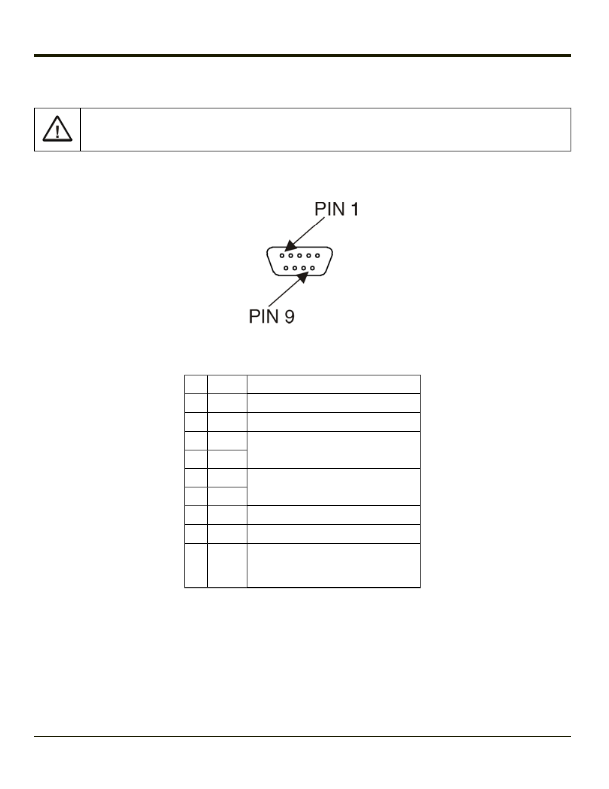
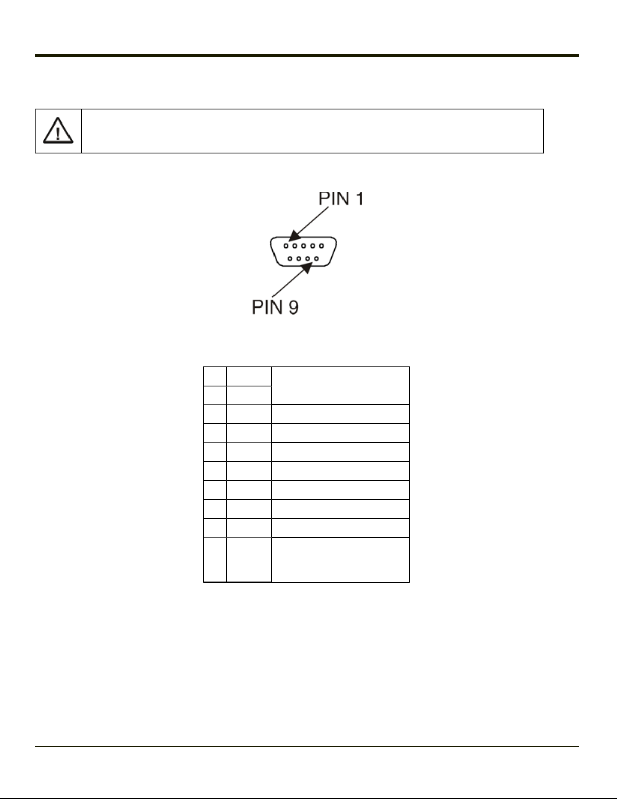
Serial Connector – COM1
COM1 provides +5v on pin 9 when enabled. Only COM1 should be used to connect an external scanner to the
Thor VX8.
The serial connector, with a (1) label, (configured as COM1) is industry-standard RS-232. The connector includes a PC/AT
standard 9–pin “D” male connector. The VMT Manager controls the function of pin 9. Pin 9 is capable of supplying +5 VDC for
an external bar code scanner. Refer to VMT Manager for more information on configuring pin 9.
Pinout
Pin Signal Description
1 DCD Data Carrier Detect – Input
2 RXD Receive Data – Input
3 TXD Transmit Data – Output
4 DTR Data Terminal Ready – Output
5 GND Signal/Power Ground
6 DSR Data Set Ready – Input
7 RTS Request to Send – Output
8 CTS Clear to Send – Input
+5VDC
9
or
RI
Note: Pin 9 of the COM port can be switched between +5V and RI. See VMT Manager.
Ring Indicator – Input (Default)
or
Bar code Scanner Power – 400mA max
2-5
Serial Connector – COM2
COM2 provides +12v on pin 9 when enabled.
Do not connect a serial bar code scanner to COM2 as this may damage the scanner, the Thor VX8 or both.
The COM2 serial connector is an industry-standard RS-232 9-pin “D” connector. The connector and its pin assignments are
shown below.
Pinout
Pin Signal Description
1 DCD Data Carrier Detect – Input
2 RXD Receive Data – Input
3 TXD Transmit Data – Output
4 DTR Data Terminal Ready – Output
5 GND Signal/Power Ground
6 DSR Data Set Ready – Input
7 RTS Request to Send – Output
8 CTS Clear to Send – Input
Ring Indicator – Input (default)
9RIor
+12VDC
Note: Pin 9 of the COM port can be switched between +12V and RI. See VMT Manager.
or
Power – 400mA max
2-6

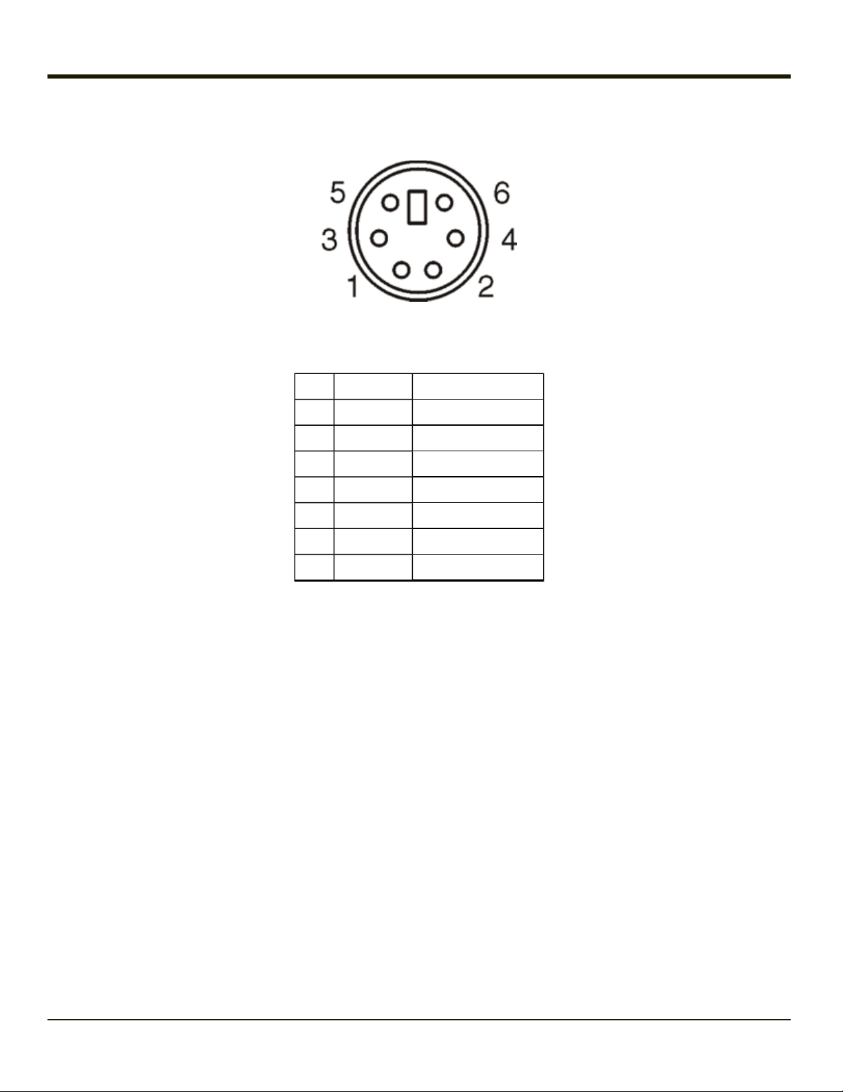
PS/2 Keyboard Connector
Pinout
Pin Signal Description
1 KBDAT_A Keyboard Data
2 – Not Connected
3 DGND System Ground
4 KBD_PWR Keyboard Power, 5V
5 KBCLK_A Keyboard Clock
6 – Not Connected
Shell CGND Chassis Ground
2-7
PS/2 Mouse Connector
Pinout
Pin Signal Description
1 MSDAT_A Mouse Data
2 – Not Connected
3 DGND System Ground
4 KBD_PWR Keyboard Power, 5V
5 MSCLK_A Mouse Clock
6 – Not Connected
Shell CGND Chassis Ground
2-8
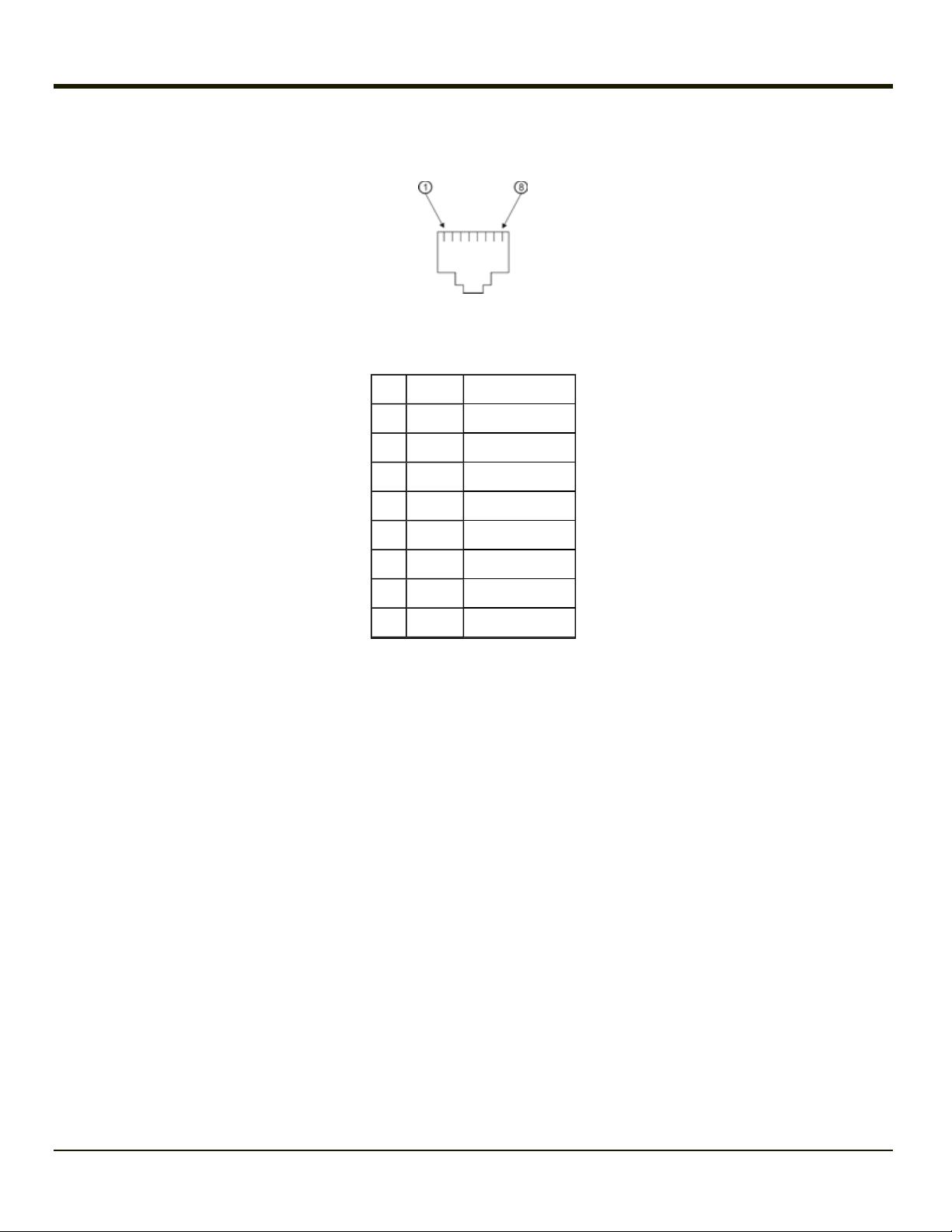
RJ45 Connector
Pinout
Pin Signal Description
1 TXP Transmit +
2 TXN Transmit –
3 RXP Receive +
4 – Not Connected
5 – Not Connected
6 RXN Receive –
7 – Not Connected
8 – Not Connected
2-9
Multipurpose Connector
The Thor VX8 Ethernet/USB connector accepts a dongle cable that provides a USB port, an Ethernet port or both. The
connector is shown below.
Pinout
Pin Signal Description
1 VCC 5 +5V power
2 RXD Receive Data, COM4
3 TXD Transmit Data, COM4
4 – Not Connected
5 +12V 12V power supply
6 USB + USB Data+
7 USB USB Data
8 GND Ground
9 – Not Connected
10 GND Ground
11 GND Ground
12 RTS COM4 Handshake
13 CTS COM4 Handshake
14 – Not Connected
15 – Not Connected
2-10
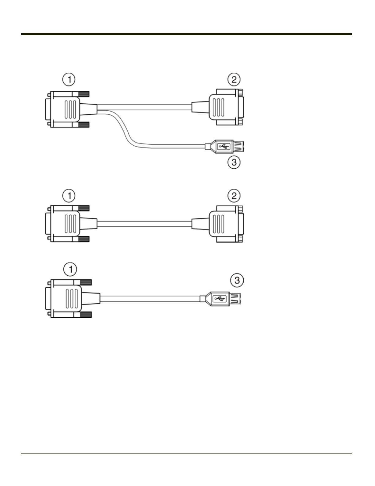
Multipurpose Dongle Cables
1. To D15 Connector on
Thor VX8
2. D9 Serial Connector
(COM4)
3. USB Connector
2-11
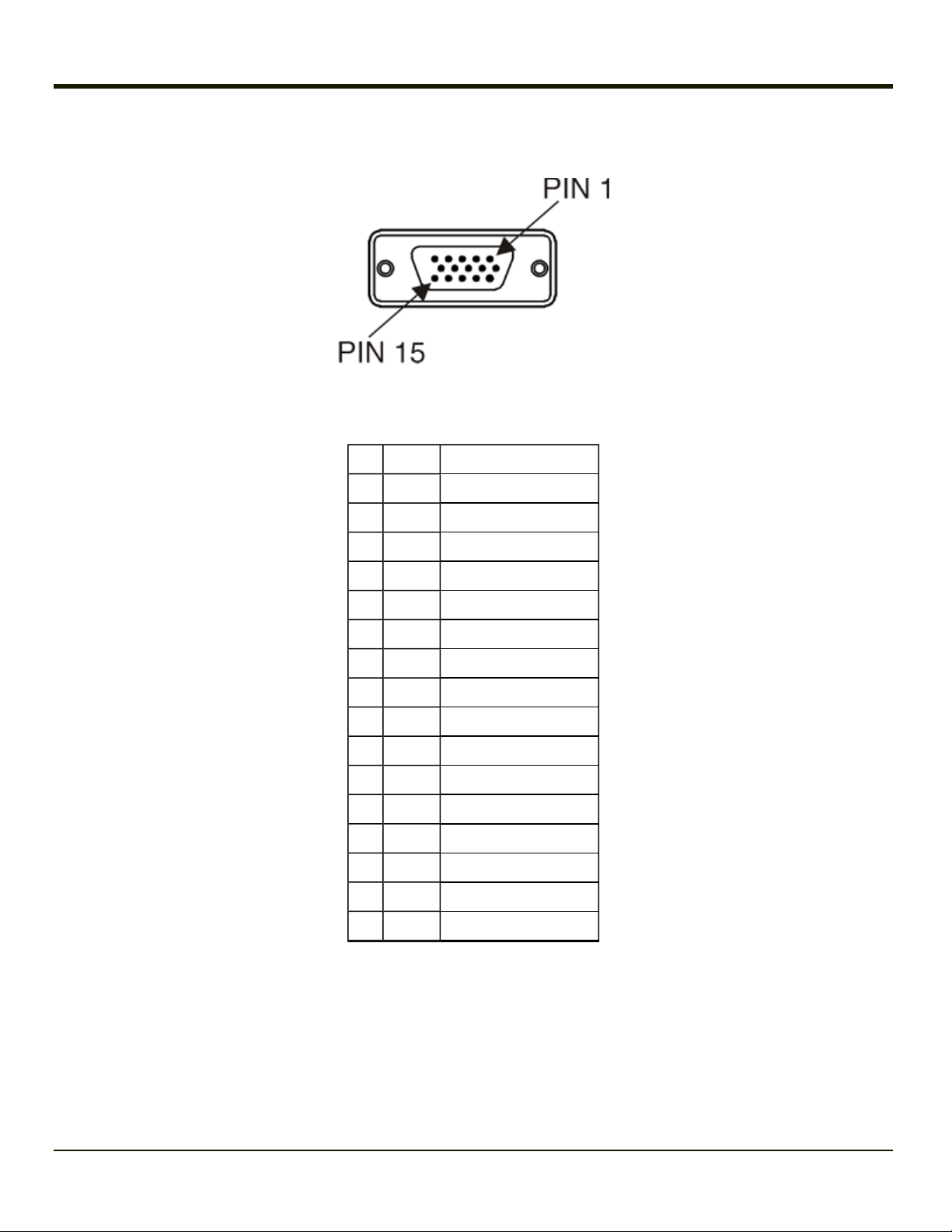
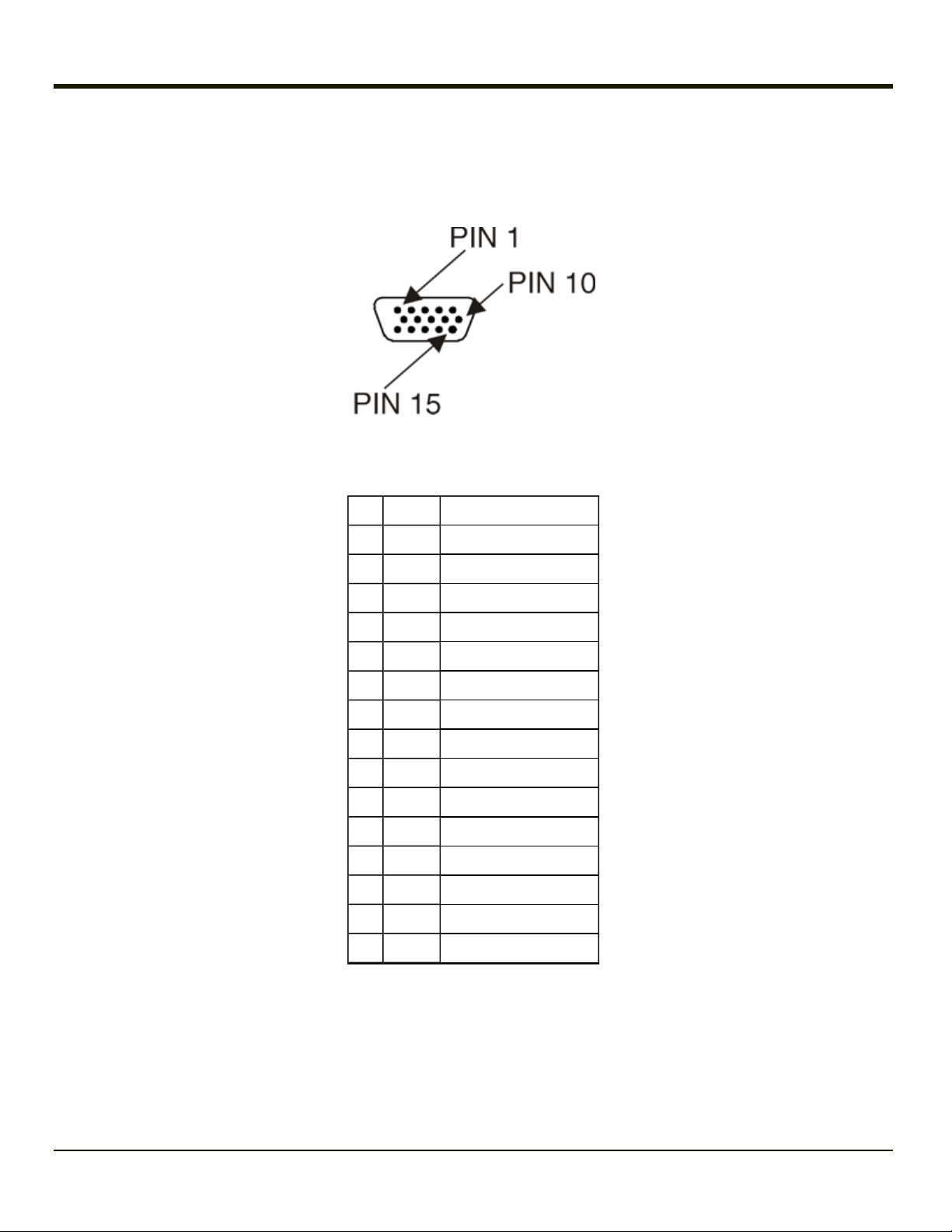
D15 Female Connector
Pinout
Pin Signal Description
Pin Signal Description
1 VCC 5 +5V power
2 RXD Receive Data, COM4
3 TXD Transmit Data, COM4
4 – Not Connected
5 +12V 12V power supply
6 USB + USB Data+
7 USB USB Data
8 GND Ground
9 – Not Connected
10 GND Ground
11 GND Ground
12 RTS COM4 Handshake
13 CTS COM4 Handshake
14 – Not Connected
15 – Not Connected
2-12
 Loading...