


2006-2008 RIDGELINE - P/NO. 61SJC02
INTRODUCTION
How to Use This Manual
This manual is divided into multiple sections. The first page of each section is marked with a black tab that lines up with its corresponding thumb index tab on this page and the back cover. You can quickly find the first page of each section without looking through a full table of contents. The symbols printed at the top corner of each page can also be used as a quick reference system.
Each section includes:
1.A table of contents, or an exploded view index showing:
•Parts disassembly sequence.
•Bolt torques and thread sizes.
•Page references to descriptions in text.
2.Disassembly/assembly procedures and tools.
3.Inspection.
4.Testing/troubleshooting.
5.Repair.
6.Adjustments.
Safety Messages
Your safety, and the safety of others, is very important. To help you make informed decisions, we have provided safety messages, and other safety information throughout this manual. Of course, it is not practical or possible to warn you about all the hazards associated with servicing this vehicle. You must use your own good judgment.
You will find important safety information in a variety of forms including:
•Safety Labels on the vehicle.
•Safety Messages preceded by a safety alert symbol  and one of three signal words, DANGER, WARNING, or CAUTION. These signal words mean:
You WILL be KILLED or SERIOUSLY HURT if you don’t follow instructions.
You CAN be KILLED or SERIOUSLY HURT if you don’t follow instructions.
You CAN be HURT if you don’t follow instructions.
• Instructions how to service this vehicle correctly and safely.
All information contained in this manual is based on the latest product information available at the time of printing. We reserve the right to make changes at anytime without notice. No part of this publication may be reproduced, or stored in a retrieval system, or transmitted, in any form by any means, electronic, mechanical, photocopying, recording, or otherwise, without the prior written permission of the publisher. This includes text, figures, and tables.
As you read this manual, you will find information that is preceded by a 


 symbol. The purpose of this message is to help prevent damage to your vehicle, other property, or the environment.
First Edition 06/2007 2,392 pages |
HONDA MOTOR CO., LTD. |
All Rights Reserved |
Service Publication Office |
Specifications apply to USA and Canada |
|
As sections with * include SRS components; special precautions are required when servicing.
General Information
Specifications
Maintenance
*Engine Electrical
Engine Mechanical
Engine Cooling
Fuel and Emissions
*Transaxle
*Steering
Suspension
*Brakes (Including VSA)
*Body
*Heating, Ventilation,
and Air Conditioning
*Body Electrical
*Audio, Navigation,
and Telematics
*Restraints

A Few Words About Safety
Service Information
The service and repair information contained in this manual is intended for use by qualified, professional technicians. Attempting service or repairs without the proper training, tools, and equipment could cause injury to you or others. It could also damage the vehicle or create an unsafe condition.
This manual describes the proper methods and procedures for doing service, maintenance, and repairs. Some procedures require the use of specially designed tools and dedicated equipment. Any person who intends to use a replacement part, service procedure, or a tool that is not recommended by Honda, must determine the risks to their personal safety and the safe operation of the vehicle.
If you need to replace any parts, always use the correct parts supplied by a Honda dealer. Never use inferior quality parts.
FOR YOUR CUSTOMER’S SAFETY
Proper service and maintenance are essential to the customer’s safety and the reliability of the vehicle. Any error or oversight while servicing a vehicle can result in faulty operation, damage to the vehicle, or injury to others.
Improper service or repairs can create an unsafe condition that can cause your customer or others to be seriously hurt or killed.
Follow the procedures and precautions in this manual and other service materials carefully.
FOR YOUR SAFETY
Because this manual is intended for the professional service technician, we do not provide warnings about many basic shop safety practices (for example, Hot parts wear gloves). If you have not received shop safety training or do not feel confident about your knowledge of safe servicing practices, we recommend that you do not attempt to do the procedures described in this manual.
Failure to properly follow instructions and precautions can cause you to be seriously hurt or killed.
Follow the procedures and precautions in this manual carefully.
Some of the most important general service safety precautions follow this text. However, we cannot warn you of every conceivable hazard that can arise in doing service and repair procedures. Only you can decide whether or not you should do a given task.
IMPORTANT SAFETY PRECAUTIONS
•Make sure you have a clear understanding of all basic shop safety practices and that you are wearing appropriate clothing and using safety equipment. When doing any service task, be especially careful of the following:
–Read all of the instructions before you begin, and make sure you have the tools, the replacement or repair parts, and the skills required to do the tasks safely and completely.
–Protect your eyes by using proper safety glasses, goggles, or face shields anytime you hammer, drill, grind, or work around pressurized air or liquids and springs or other stored-energy components. If there is any doubt, put on eye protection.
–Use other protective wear when necessary, such as gloves or safety shoes. Handling hot or sharp parts can cause severe burns or cuts. Before you grab something that looks like it can hurt you, stop and put on gloves.
–Protect yourself and others whenever you have the vehicle up in the air. Anytime you raise the vehicle, either with a lift or a jack, make sure that it is always securely supported. Use jack stands if needed.
–Protect yourself by wearing an approved welding helmet, gloves, and safety shoes anytime you are welding. You can receive burns from hot parts; allow the parts to cool before working in that area.
–Protect yourself from paints and harmful chemicals by wearing an approved respirator, eye protection, and gloves whenever you are painting. Spray paint only in an approved paint booth that is well ventilated.
•Make sure the engine is off before you begin any servicing procedures, unless the instruction tells you to do otherwise. This will help eliminate several potential hazards:
–Carbon monoxide poisoning from engine exhaust. Be sure there is adequate ventilation whenever you run the engine.
–Burns from hot parts or coolant. Let the engine and exhaust system cool before working in those areas.
–Injury from moving parts. If the instruction tells you to run the engine, be sure your hands, fingers, and clothing are out of the way.
•Gasoline vapors and hydrogen gases from batteries are explosive. To reduce the possibility of a fire or explosion, be careful when working around gasoline or batteries.
–Use only a nonflammable solvent, not gasoline, to clean parts.
–Never drain or store gasoline in an open container.
–Keep all cigarettes, sparks, and flames away from the battery and all fuel-related parts.

SUPPLEMENTAL RESTRAINT SYSTEM (SRS)
The Ridgeline SRS includes a driver’s airbag in the steering wheel hub, a passenger’s airbag in the dashboard above the glove box, seat belt tensioners in the front seat belt retractors, side curtain airbags in the sides of the roof, and side airbags in the front seat-backs. Information necessary to safely service the SRS is included in this Service Manual. Items marked with an asterisk (  ) on the contents page include or are located near SRS components. Servicing, disassembling, or replacing these items requires special precautions and tools, and should be done by an authorized Honda dealer.
•To avoid rendering the SRS inoperative, which could lead to personal injury or death in the event of a severe frontal or side collision, all SRS service work should be done by an authorized Honda dealer.
•Improper service procedures, including incorrect removal and installation of the SRS, could lead to personal injury caused by unintentional deployment of the airbags and/or side airbags.
•Do not bump or impact the SRS unit, front impact sensors, or side impact sensors when the ignition switch is ON (II), or for at least 3 minutes after the ignition switch is turned OFF; otherwise, the system may fail in a collision, or the airbags may deploy.
•SRS electrical connectors are identified by yellow color coding. Related components are located in the steering column, front console, dashboard, dashboard lower panel, in the dashboard above the glove box, in the front seats, in the roof side, and around the floor. Do not use electrical test equipment on these circuits.

General Information
Chassis and Paint Codes
’06 Model ...................................................................... |
. 1-2 |
’07 Model ...................................................................... |
. 1-3 |
’08 Model ...................................................................... |
. 1-4 |
Identification Number Locations ................... |
. 1-5 |
Danger/Warning/Caution Label Locations |
.... 1-6 |
Under-hood Emission Control Label .............. |
. 1-9 |
Lift and Support Points ................................... |
. 1-10 |
Towing ............................................................. |
. 1-11 |
Parts Marking ................................................... |
. 1-12 |
Precautions for Variable Torque |
|
Management 4WD (VTM-4) System .......... |
. 1-12 |

 General Information
Chassis and Paint Codes
’06 Model |
|
Vehicle Identification Number |
Engine Number |
2HJ YK1 6 2 * 6 H 500001 |
J35A9 - 1000001 |
a b |
c d e f g h |
a |
b |
a. Manufacturer, Make, and Type of Vehicle |
a. Engine Type |
||
2HJ: |
Honda of Canada Mfg., |
J35A9: 3.5 L SOHC VTEC Sequential Multiport |
|
|
Honda Canada Inc. |
|
Fuel-injected engine |
|
Honda Light duty truck |
b. Serial Number |
|
b. Line, Body, and Engine Type |
|
|
|
YK1: |
Ridgeline/J35A9 |
Transmission Number |
|
c. Body Type and Transmission Type |
|||
6:4-door/5-speed Automatic
d. Vehicle Grade (Series) |
BJFA |
- 8000001 |
||
USA models |
||||
|
|
|||
2: |
RT |
|
|
|
4: |
RTS |
a |
b |
|
5: |
RTL |
|||
|
|
|||
|
RTL with Moonroof and XM radio |
|
|
|
|
RTL with Moonroof and XM radio and |
a. Transmission Type |
||
|
Navigation System |
BJFA: 5-speed Automatic |
||
Canada models |
b. Serial Number |
|||
4:LX
5:EXL
|
EXL SR |
Paint Code |
|
|
||
|
EXL with Navigation System |
|
Code |
Color |
USA |
Canada |
e. Check Digit |
|
|
|
models |
models |
|
f. Model Year |
|
NH-578 |
White |
○ |
|
|
6: |
’06 |
|
NH-689M |
Billet Silver Metallic |
○ |
○ |
g. Factory Code |
|
B-92P |
Nighthawk Black Pearl |
○ |
○ |
|
H: |
Alliston, Ontario Factory in Canada |
|
B-533M |
Steel Blue Metallic |
○ |
○ |
h. Serial Number |
|
G-521M |
Amazon Green Metallic |
○ |
○ |
|
500001: USA models |
|
R-519P |
Redrock Pearl |
○ |
○ |
|
000001: Canada models |
|
|
|
|
|
|
COLOR LABEL
Vehicle Identification Number
and Federal Motor Vehicle
Safety Standard Certification.
Vehicle Identification Number
and Canadian Motor Vehicle
Safety Standard Certification.
1-2

’07 Model |
|
Vehicle Identification Number |
Engine Number |
2HJ YK1 6 2 * 7 H 500001 |
J35A9 - 2000001 |
a b |
c d e f g h |
a |
b |
a. Manufacturer, Make, and Type of Vehicle |
a. Engine Type |
||
2HJ: |
Honda of Canada Mfg., |
J35A9: 3.5 L SOHC VTEC Sequential Multiport |
|
|
Honda Canada Inc. |
|
Fuel-injected engine |
|
Honda Light duty truck |
b. Serial Number |
|
b. Line, Body, and Engine Type |
|
|
|
YK1: |
Ridgeline/J35A9 |
Transmission Number |
|
c. Body Type and Transmission Type |
|||
6:4-door/5-speed Automatic
d. Vehicle Grade (Series) |
BJFA |
- 9000001 |
|
|
|
USA models |
|
|
|||
|
|
|
|
||
2: |
RT |
|
|
|
|
3: |
RTX |
a |
b |
|
|
4: |
RTS |
|
|
||
|
|
|
|
||
5: |
RTL |
|
|
|
|
|
RTL with Navigation System |
a. Transmission Type |
|
|
|
Canada models |
BJFA: 5-speed Automatic |
|
|
||
4: |
LX |
b. Serial Number |
|
|
|
5: |
EXL |
|
|
|
|
|
EXL with Moonroof |
Paint Code |
|
|
|
|
EXL with Moonroof and Navigation System |
|
|
||
e. Check Digit |
Code |
Color |
USA |
Canada |
|
f. Model Year |
|
|
models |
models |
|
7: |
’07 |
NH-578 |
White |
|
○ |
g. Factory Code |
NH-578X |
White |
○ |
|
|
H: |
Alliston, Ontario Factory in Canada |
NH-689M |
Billet Silver Metallic |
○ |
○ |
h. Serial Number |
NH-705M |
Nimbus Gray Metallic |
○ |
○ |
|
500001: USA models |
NH-707 |
Formal Black II |
|
○ |
|
000001: Canada models |
NH-707X |
Formal Black II |
○ |
○ |
|
|
|
B-533M |
Steel Blue Metallic |
○ |
○ |
|
|
G-525M |
Dark Silver Sage Metallic |
○ |
○ |
|
|
R-529P |
Dark Cherry Pearl |
○ |
○ |
COLOR LABEL
Vehicle Identification Number
and Federal Motor Vehicle
Safety Standard Certification.
Vehicle Identification Number
and Canadian Motor Vehicle
Safety Standard Certification.
1-3
General Information
Chassis and Paint Codes (cont’d) |
|
|
|
|
|
|
||||||||||||||||||
’08 Model |
|
|
|
|
|
|
Engine Number |
|||||||||||||||||
Vehicle Identification Number |
|
|||||||||||||||||||||||
|
|
J35A9 |
- 4000001 |
|
||||||||||||||||||||
|
|
|
|
|
|
|
|
|
|
|
|
|
|
|
|
|
|
|
|
|
||||
|
2HJ |
|
YK1 6 2 * 8 |
|
H 500001 |
|
|
|
|
|
|
|||||||||||||
|
|
|
|
|
|
|
|
|
||||||||||||||||
|
|
|
|
|
|
|
|
|
|
|
|
|
|
|
|
|
|
|
|
|
|
|
|
|
|
|
|
|
|
|
|
|
|
|
|
|
|
|
|
|
|
|
|
|
|
|
|
|
|
|
|
|
|
|
|
|
|
|
|
|
|
|
|
|
|
|
|
|
a |
b |
||||
a |
b |
c d e f |
g h |
|||||||||||||||||||||
|
|
|
|
|
|
|||||||||||||||||||
|
|
|
|
|
|
|
|
|
|
|
|
|
|
|
|
|
|
|
a. Engine Type |
|||||
a. Manufacturer, Make, and Type of Vehicle |
|
|
J35A9: |
3.5 L SOHC VTEC Sequential Multiport |
||||||||||||||||||||
|
2HJ: |
Honda of Canada Mfg., |
|
|
|
Fuel-injected engine |
||||||||||||||||||
|
|
|
|
Honda Canada Inc. |
|
b. Serial Number |
||||||||||||||||||
|
|
|
|
Honda Light duty truck |
|
|
|
|
|
|
||||||||||||||
b. Line, Body, and Engine Type |
|
Transmission Number |
||||||||||||||||||||||
|
YK1: |
Ridgeline/J35A9 |
|
|||||||||||||||||||||
c. Body Type and Transmission Type |
|
|
|
|
|
|
||||||||||||||||||
6: |
4-door/5-speed Automatic |
|
|
BJFA |
- 1000001 |
|
||||||||||||||||||
|
|
|
|
|
|
|
|
|
|
|
|
|
|
|
|
|
|
|
|
|
||||
d.Vehicle Grade (Series)
USA models
2: |
RT |
a |
b |
|
3: |
RTX |
|||
|
|
|||
4: |
RTS |
|
|
|
5: |
RTL |
a. Transmission Type |
||
|
RTL with Navigation System |
BJFA: 5-speed Automatic |
||
Canada models |
b. Serial Number |
|||
4:LX
5:EXL
|
EXL with Moonroof |
Paint Code |
|
|
||
|
EXL with Moonroof and Navigation System |
|
Code |
Color |
USA |
Canada |
e. Check Digit |
|
|
|
models |
models |
|
f. Model Year |
|
NH-578 |
White |
|
○ |
|
8: |
’08 |
|
NH-578X |
White |
○ |
|
g. Factory Code |
|
NH-689M |
Billet Silver Metallic |
○ |
○ |
|
H: |
Alliston, Ontario Factory in Canada |
|
NH-705M |
Nimbus Gray Metallic |
○ |
○ |
h. Serial Number |
|
NH-707 |
Formal Black II |
|
○ |
|
500001: USA models |
|
NH-707X |
Formal Black II |
○ |
○ |
|
000001: Canada models |
|
B-533M |
Steel Blue Metallic |
○ |
○ |
|
|
|
|
R-529P |
Dark Cherry Pearl |
○ |
○ |
COLOR LABEL
Vehicle Identification Number
and Federal Motor Vehicle
Safety Standard Certification.
Vehicle Identification Number
and Canadian Motor Vehicle
Safety Standard Certification.
1-4

Identification Number Locations
Vehicle Identification |
Vehicle Identification |
Number (VIN) |
Number (VIN) |
Bar Code |
Engine Number |
Transmission Number |
Engine Number |
|
|
1-5

General Information
Danger/Warning/Caution Label Locations
Passenger’s Compartment:
SRS INFORMATION
USA models
FRONT PASSENGER
MODULE DANGER
SRS WARNING
INFORMATION
FRONT PASSENGER AIRBAG WARNING
(CHILD SEAT)
USA models
SIDE AIRBAG MODULE DANGER
STEERING COLUMN NOTICE
MONITOR NOTICE |
FRONT SEAT BELT TENSIONER |
|
WARNING |
||
|
VTM-4
LOCK INFORMATION
1-6

Steering Wheel:
DRIVER MODULE DANGER
CABLE REEL CAUTION
Rear Compartment:
ROOF SIDE
MODULE DANGER
(cont’d)
1-7
General Information
Danger/Warning/Caution Label Locations (cont’d)
’06 Model:
SRS WARNING |
|
|
SERVICE INFORMATION |
ENGINE COOLANT |
(Under-hood Emission |
INFORMATION |
Control) |
AIR CONDITIONING |
|
BATTERY |
INFORMATION |
RADIATOR CAP |
DANGER |
|
|
|
|
DANGER |
|
’07-08 Models:
ENGINE COOLANT
INFORMATION
SERVICE INFORMATION SRS WARNING (Under-hood Emission
Control)
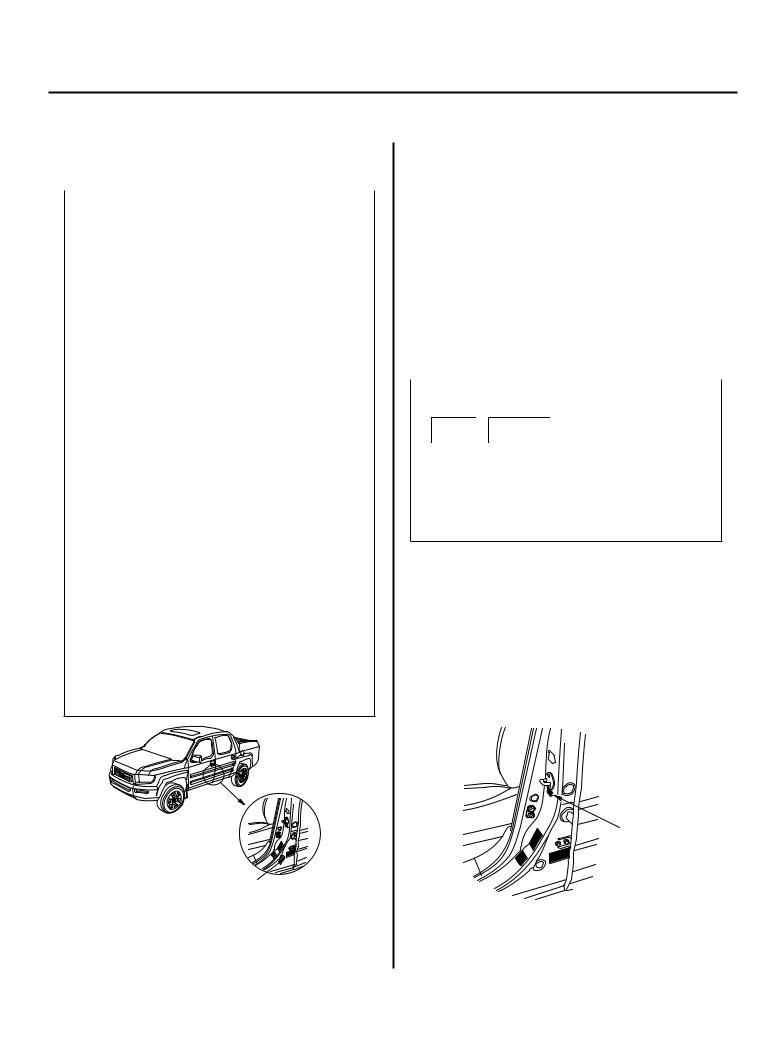
Driver’s Doorjamb:
TIRE INFORMATION
SIDE AIRBAG INFORMATION
Located on driver’s doorjamb and passenger’s doorjamb (not shown)
Left Bed Side Panel:
PORTABLE FUEL TANK WARNING
AIR CONDITIONING |
|
BATTERY |
INFORMATION |
RADIATOR CAP |
DANGER |
|
|
|
|
DANGER |
|
1-8

Under-hood Emission Control Label
Emission Group Identification
Example:
’06-07 Models
VEHICLE EMISSION CONTROL INFORMATION
THIS VEHICLE CONFORMS TO U.S. EPA TIER 2 BIN 5 REGULATIONS APPLICABLE TO 2006 MODEL YEAR NEW LIGHT-DUTY TRUCKS AND CALIFORNIA REGULATIONS APPLICABLE TO 2006 MODEL YEAR NEW LEV II ULEV LIGHT-DUTY TRUCKS.
2WU-TWC, TWC, 2A/F SENSOR, 2HO2S, EGR, SFI
6HNXT03.5AKR
6HNXR0156BBA OBD II CERTIFIED 3.5L
VALVE LASH (IN) 0.22±0.02mm (COLD)
(EX) 0.30±0.02mm (COLD)
NO OTHER ADJUSTMENTS NEEDED.
EVAP CANISTER |
TO EVAP CANISTER |
PURGE VALVE |
|
FRONT
PCV VALVE
EXHAUST EMISSIONS STANDARDS
ARB: LEV II ULEV (CERTIFICATION AND IN-USE) EPA: TIER 2 BIN 5 (CERTIFICATION AND IN-USE)
LOADED I/M TESTING OF THIS VEHICLE MUST BE
CONDUCTED ON A FOUR-WHEEL DRIVE SPEED
SYNCHRONIZED DYNAMOMETER. OTHERWISE, A
NON-LOADED TEST PROCEDURE MUST BE PERFORMED.
X• C
HONDA MOTOR CO. , LTD. |
RJE-A01 |
’08 Model
VEHICLE EMISSION CONTROL INFORMATION
CONFORMS TO REGULATIONS : 2008MY
U.S. EPA: T2B5 LDT3 |
OBD: CA OBD II |
FUEL: GASOLINE |
ARB: LEV II ULEV LDT2 |
OBD: CA OBD II |
FUEL: GASOLINE |
2W U-TWC, TWC, 2A/F SENSO R, 2HO2S, EGR, SFI |
||
8HNXT03.5MKR |
8HNXR0163BBA |
3 . 5 L |
LOADEDI/MTESTINGOFTHISVEHICLEMUSTBECONDUCTEDONAFOUR-WHEELDRIVESPEEDSYNCHRONIZED
DYNAMOMETER.OTHERWISE,ANON-LOADEDTESTPROCEDUREMUSTBEPERFORMED.
INFORMATION
THEFACTORYINSTALLED LONG-LIFECOOLANTMUSTBEREPLACEDACCORDING TOMAINTENANCEMINDERSUBCODE5,ORAT10YEARSWHICHEVERCOMESFIRST.
THEREAFTER EVERY5 YEARS.
WHENADDING ORREPLACING THE COOLANT,ALWAYS USEHondaRECOMMENDEDGENUINELONG-LIFEANTI-FREEZE/COOLANTTYPE2.THISCOOLANTIS PRE-MIXED
WITH50% DISTILLED WATER. ITDOESNOTREQUIREANYADDITIONALMIXING.
NEVERDILUTETHECOOLANT, ORTHELIFEOFTHEENGINEMAYBESERIOUSLY SHORTENED.
CHECKORADDTHECOOLANTATTHERESERVE TANK,NOTTHERADIATOR.
FORFURTHERINFORMATIONONTHECOOLING SYSTEM,READ THEOWNER’SMANUALOR CHECK WITHYOURHondaDEALER.
|
7• D |
HONDA MOTOR CO. , LTD. |
RJE-A03 |
’06 Model
THIS VEHICLE CONFORMS TO U.S. EPA TIER 2 BIN 5 REGULATIONS APPLICABLE TO 2006 MODEL YEAR NEW LIGHT-DUTY TRUCKS AND CALIFORNIA REGULATIONS APPLICABLE TO 2006 MODEL YEAR NEW LEV II ULEV LIGHT-DUTY TRUCKS.
’07 Model
THIS VEHICLE CONFORMS TO U.S. EPA TIER 2 BIN 5 REGULATIONS APPLICABLE TO 2007 MODEL YEAR NEW LIGHT-DUTY TRUCKS AND CALIFORNIA REGULATIONS APPLICABLE TO 2007 MODEL YEAR NEW LEV II ULEV LIGHT-DUTY TRUCKS.
Test Group and Evaporative Family
Test Group: |
|
8 HNX T 03.5 |
MKR |
a b c d |
e |
a.Model Year
6:’06
7:’07
8:’08
b.Manufacturer Subcode
HNX: HONDA
c.Family Type
T: LDT
d.Displacement
e.Sequence Characters
AKR: ’06 model TKR: ’07 model MKR: ’08 model
Evaporative Family:
8 HNX R 0163 BBA
a b c d |
e |
a.Model Year
6:’06
7:’07
8:’08
b.Manufacturer Subcode
HNX: HONDA
c.Family Type
R: EVAP/ORVR
d.Canister Working Capacity Group
0156: ’06 model 0163: ’07-08 models
e.Sequence Characters
BBA: ’06 and ’08 models BBY: ’07 model
1-9
General Information
Lift and Support Points
NOTE: If you are going to remove heavy components such as suspension or the fuel tank from the rear of the vehicle, first support the front of the vehicle with tall safety stands. When substantial weight is removed from the rear of the vehicle, the center of gravity can change, causing the vehicle to tip forward on the lift.
Vehicle Lift
1.Position the lift blocks (A) under the vehicle’s front support points (B) and rear support points (C).
A
B C
2.Raise the lift a few inches, and rock the vehicle gently to be sure it’s firmly supported.
3.Raise the lift to its height, and inspect the vehicle support points for solid contact with the lift blocks.
Safety Stands
To support the vehicle on safety stands, use the same support points (B and C) as for a vehicle lift. Always use safety stands when working on or under any vehicle that is supported only by a jack.
Floor Jack
1.When lifting the front of the vehicle, set the parking brake. When lifting the rear of the vehicle, put the shift lever in the P position.
2.Block the wheels that are not being lifted.
3.Position the floor jack under the front jacking bracket (A) or the rear jacking bracket (B). Center the jacking bracket on the jack lift platform (C), and jack up the vehicle high enough to fit the safety stands under it.
A C
B C
4.Position the safety stands under the support points and adjust them so the vehicle is level.
5.Lower the vehicle onto the stands.
1-10

Towing
If the vehicle needs to be towed, call a professional towing service. Never tow the vehicle behind another vehicle with a rope or chain. It is very dangerous.
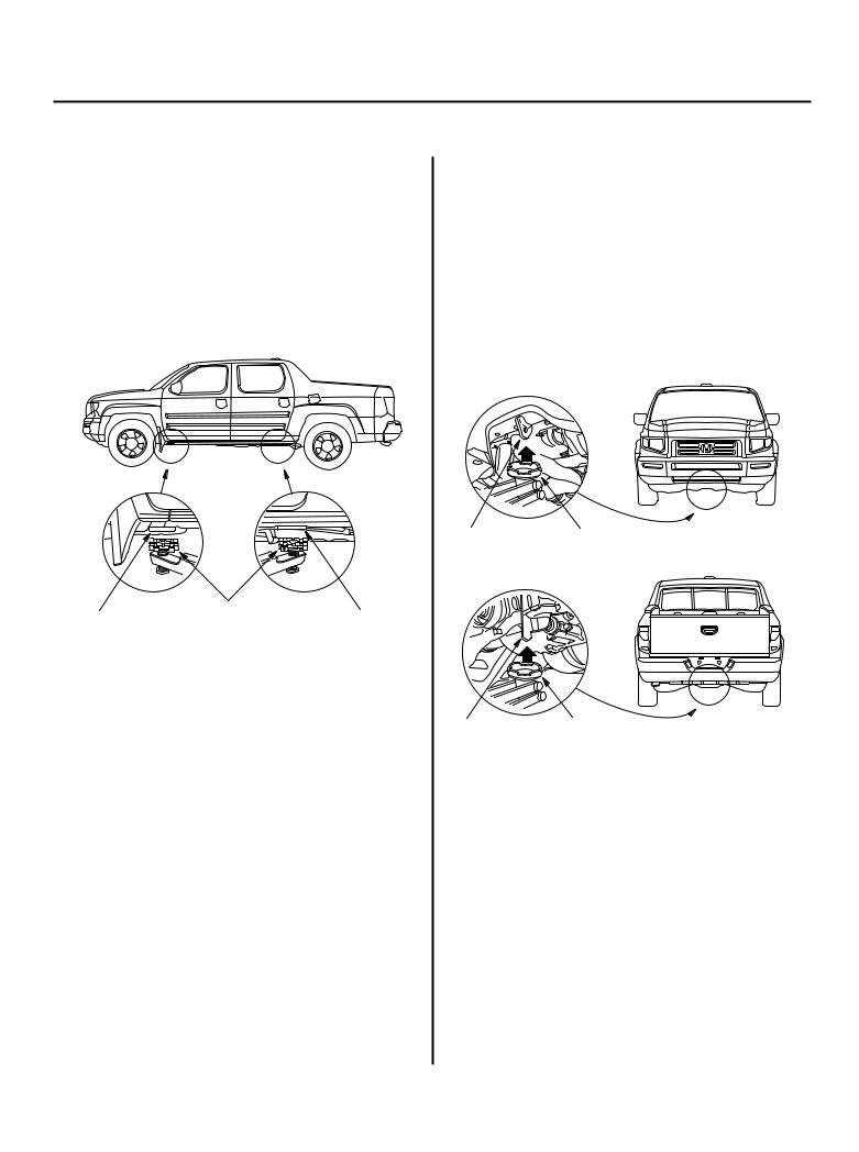
Emergency Towing
There are three popular methods of towing a vehicle.
Flat-bed Equipment The operator loads the vehicle on the back of a truck. This is the only way of transporting the vehicle.
To accommodate flat-bed equipment, the vehicle is equipped with a front towing hook (A), front tie down hook slot (B), rear towing hook (C), and rear tie down hook slot (D).
The towing hooks can be used with a winch to pull the vehicle onto the truck, and the tie down hook slots can be used to secure the vehicle to the truck.
Front:
A
B
Rear:
C
D
Wheel Lift Equipment The tow truck uses two pivoting arms that go under the tires (front or rear) and lift them off the ground. The other two wheels remain on the ground. Never tow the vehicle with this wheel lift equipment.
Sling-type Equipment The tow truck uses metal cables with hooks on the ends. These hooks go around parts of the frame or suspension, and the cables lift that end of the vehicle off the ground. The vehicle’s suspension and body can be seriously damaged if this method of towing is attempted. This method of towing the Ridgeline is unacceptable.
The only recommended way of towing the Ridgeline is on a flat-bed truck.
•Towing the Ridgeline with only two wheels on the ground will damage parts of the 4WD system. If the vehicle is damaged, it should be transported on a flatbed truck or trailer.
•Trying to lift or tow the vehicle by the bumpers will cause serious damage. The bumpers are not designed to support the vehicle’s weight.
For non-emergency towing information, refer to the owner’s manual.
Trailer Towing (’07-08 USA RTX model)
This vehicle has a class three trailer hitch (A) as standard equipment. The cover (B), the ball mount (C), the hitch pin (D), and the hitch pin clip (E) are stored in the in-bed trunk.
A A
E
B
D
C
1-11

General Information
Parts Marking
To deter vehicle theft, certain major components are marked with the vehicle identification number (VIN). Original parts have self-adhesive labels. Replacement body parts have generic self-adhesive labels. These labels should not be removed. The original engine or transmission VIN plates are not transferable to the replacement engine or transmission.
NOTE: Be careful not to damage the parts marking labels during body repair. Mask the labels before repairing the part.
Precautions for Variable Torque Management 4WD (VTM-4) System
This vehicle is equipped with the Variable Torque Management 4WD (VTM-4) System. The VTM-4 system distributes driving torque between the front and rear wheels when accelerating and when wheel spin occurs.
The VTM-4 system does not have a manual switch to disable the 4WD system. Whenever service work requires spinning the front or rear wheels with the engine, always lift and support the vehicle so all four wheels are off the ground.
1-12

Specifications
Standards and Service Limits
Engine Electrical ........................................................... |
2-2 |
Engine Assembly .......................................................... |
2-2 |
Cylinder Head ............................................................... |
2-3 |
Engine Block ................................................................. |
2-4 |
Engine Lubrication ....................................................... |
2-5 |
Cooling System ............................................................ |
2-5 |
Fuel and Emissions ...................................................... |
2-5 |
Automatic Transmission and A/T Differential ........... |
2-6 |
Rear Differential ............................................................ |
2-15 |
Steering ......................................................................... |
2-15 |
Suspension ................................................................... |
2-15 |
Brakes ............................................................................ |
2-16 |
Air Conditioning ........................................................... |
2-16 |
Design Specifications
Dimensions ................................................................... |
2-17 |
Weight ........................................................................... |
2-17 |
Engine ............................................................................ |
2-17 |
Starter ............................................................................ |
2-17 |
Automatic Transmission .............................................. |
2-18 |
Steering ......................................................................... |
2-18 |
Suspension ................................................................... |
2-18 |
Wheel Alignment .......................................................... |
2-18 |
Brakes ............................................................................ |
2-18 |
Tires ............................................................................... |
2-18 |
Air Conditioning ........................................................... |
2-18 |
Electrical Ratings .......................................................... |
2-19 |
Body Specifications ...................................................... |
2-20 |
Standards and Service Limits
Engine Electrical
|
|
Item |
Measurement |
Qualification |
Standard or New |
Service Limit |
|
|
Ignition coil |
Rated voltage |
|
12 V |
|
|
|
|
Firing order |
|
1 4 2 5 3 6 |
|
|
|
Spark plug |
Type |
|
NGK: IZFR5K11 |
|
|
|
|
|
|
DENSO: SKJ16DR-M11 |
|
|
|
|
Gap |
|
1.0 1.1 mm (0.039 0.043 in.) |
――― |
|
|
Ignition timing |
At idle |
In N or P position |
10±2 ° BTDC |
|
|
|
|
Check the red mark |
|
|
|
|
|
Drive belt |
Tension |
|
Auto tensioner |
|
|
|
Alternator |
Output |
At 13.5 V and |
130 A |
|
|
|
|
|
normal engine |
|
|
|
|
|
|
temperature |
|
|
|
|
|
Coil (rotor) resistance |
At 68 °F (20 °C) |
2.3 2.7 |
|
|
|
|
Slip ring O.D. |
|
14.2 14.4 mm (0.56 0.57 in.) |
13.8 mm (0.54 in.) |
|
|
|
Brush length |
|
10.5 mm (0.41 in.) |
1.5 mm (0.06 in.) |
|
|
|
Brush spring tension |
|
2.94 3.53 N (0.30 0.36 kgf, 0.66 0.80 lbf) |
|
|
|
Starter |
Output |
|
1.6 kW |
|
|
|
|
Commutator mica depth |
|
0.4 0.6 mm (0.016 0.024 in.) |
0.20 mm (0.008 in.) |
|
|
|
Commutator runout |
|
0.05 mm (0.002 in.) max. |
0.1 mm (0.004 in.) |
|
|
|
Commutator O.D. |
|
29.3 29.5 mm (1.154 1.161 in.) |
28.8 mm (1.134 in.) |
|
|
|
Brush length |
|
7.7 8.0 mm (0.30 0.31 in.) |
0.9 mm (0.04 in.) |
|
|
|
Brush spring tension (new) |
|
15.9 19.5 N (1.62 1.99 kgf, 3.57 4.39 lbf) |
|
Engine Assembly
Item |
Measurement |
Qualification |
Standard or New |
Service Limit |
Compression |
Pressure |
Minimum |
930 kPa (9.5 kgf/cm2, 135 psi) |
――― |
|
Check the engine with the starter |
Maximum |
200 kPa (2.0 kgf/cm2, 28 psi) |
――― |
|
cranking |
variation |
|
|
2-2

Cylinder Head
Item |
Measurement |
Qualification |
Standard or New |
Service Limit |
Head |
Warpage |
|
――― |
0.05 mm (0.002 in.) |
|
Height |
|
120.95 121.05 mm (4.762 4.766 in.) |
――― |
Camshaft |
End play |
|
0.05 0.20 mm (0.002 0.008 in.) |
0.20 mm (0.008 in.) |
|
Camshaft-to-holder oil clearance |
|
0.050 0.089 mm (0.0020 0.0035 in.) |
0.15 mm (0.006 in.) |
|
Total runout |
|
0.03 mm (0.001 in.) max. |
0.04 mm (0.002 in.) |
|
Cam lobe height |
Intake, primary |
35.041 mm (1.3796 in.) |
――― |
|
|
Intake, mid |
36.445 mm (1.4348 in.) |
――― |
|
|
Intake, |
35.284 mm (1.3891 in.) |
――― |
|
|
secondary |
|
|
|
|
Exhaust |
36.326 mm (1.4302 in.) |
――― |
Valve |
Clearance (cold) |
Intake |
0.20 0.24 mm (0.008 0.009 in.) |
――― |
|
|
Exhaust |
0.28 0.32 mm (0.011 0.013 in.) |
――― |
|
Stem O.D. |
Intake |
5.485 5.495 mm (0.2159 0.2163 in.) |
5.455 mm (0.2148 in.) |
|
|
Exhaust |
5.450 5.460 mm (0.2146 0.2150 in.) |
5.420 mm (0.2134 in.) |
|
Stem-to-guide clearance |
Intake |
0.020 0.045 mm (0.0008 0.0018 in.) |
0.08 mm (0.003 in.) |
|
|
Exhaust |
0.055 0.080 mm (0.0022 0.0031 in.) |
0.11 mm (0.004 in.) |
Valve seat |
Width |
Intake |
1.25 1.55 mm (0.049 0.061 in.) |
2.00 mm (0.079 in.) |
|
|
Exhaust |
1.25 1.55 mm (0.049 0.061 in.) |
2.00 mm (0.079 in.) |
|
Stem installed height |
Intake |
46.75 47.55 mm (1.841 1.872 in.) |
47.80 mm (1.882 in.) |
|
|
Exhaust |
46.68 47.48 mm (1.838 1.869 in.) |
47.73 mm (1.879 in.) |
Valve spring |
Free length |
Intake |
51.54 mm (2.029 in.) |
――― |
|
|
Exhaust |
51.06 mm (2.010 in.) |
――― |
Valve guide |
I.D. |
Intake |
5.515 5.530 mm (0.2171 0.2177 in.) |
5.55 mm (0.219 in.) |
|
|
Exhaust |
5.515 5.530 mm (0.2171 0.2177 in.) |
5.55 mm (0.219 in.) |
|
Installed height |
Intake |
21.20 22.20 mm (0.835 0.874 in.) |
――― |
|
|
Exhaust |
20.60 21.60 mm (0.811 0.850 in.) |
――― |
Rocker arm |
Arm-to-shaft clearance |
Intake |
0.026 0.067 mm (0.0010 0.0026 in.) |
0.067 mm (0.0026 in.) |
|
|
Exhaust |
0.026 0.077 mm (0.0010 0.0030 in.) |
0.077 mm (0.0030 in.) |
2-3

Standards and Service Limits
Engine Block
Item |
Measurement |
Qualification |
Standard or New |
Service Limit |
Block |
Warpage of deck |
|
0.07 mm (0.003 in.) max. |
0.10 mm (0.004 in.) |
|
Bore diameter |
|
89.000 89.015 mm (3.5039 3.5045 in.) |
89.065 mm (3.5065 in.) |
|
Bore taper |
|
――― |
0.05 mm (0.002 in.) |
|
Reboring limit |
|
――― |
0.25 mm (0.01 in.) |
Piston |
Skirt O.D. at 16.0 mm (0.63 in.) from |
|
88.975 88.985 mm (3.5029 3.5033 in.) |
88.965 mm (3.5026 in.) |
|
bottom of skirt |
|
|
|
|
Clearance in cylinder |
|
0.015 0.040 mm (0.0006 0.0016 in.) |
0.08 mm (0.003 in.) |
|
Ring groove width |
Top |
1.240 1.250 mm (0.0488 0.0492 in.) |
1.27 mm (0.050 in.) |
|
|
Second |
1.220 1.230 mm (0.0480 0.0484 in.) |
1.25 mm (0.049 in.) |
|
|
Oil |
2.805 2.825 mm (0.1104 0.1112 in.) |
2.85 mm (0.112 in.) |
Piston ring |
Ring-to-groove clearance |
Top |
0.055 0.080 mm (0.0022 0.0031 in.) |
0.15 mm (0.006 in.) |
|
|
Second |
0.030 0.055 mm (0.0012 0.0022 in.) |
0.13 mm (0.005 in.) |
|
Ring end gap |
Top |
0.20 0.35 mm (0.008 0.014 in.) |
0.60 mm (0.024 in.) |
|
|
Second |
0.40 0.55 mm (0.016 0.022 in.) |
0.70 mm (0.028 in.) |
|
|
Oil |
0.20 0.70 mm (0.008 0.028 in.) |
0.80 mm (0.031 in.) |
Piston pin |
O.D. |
|
21.962 21.965 mm (0.8646 0.8648 in.) |
21.954 mm (0.8643 in.) |
|
Pin-to-piston clearance |
|
0.0050 to 0.0010 mm |
0.004 mm (0.0002 in.) |
|
|
|
( 0.00020 to 0.00004 in.) |
|
Connecting rod |
Pin-to-rod clearance |
|
0.005 0.014 mm (0.0002 0.0006 in.) |
0.019 mm (0.0007 in.) |
|
Small-end bore diameter |
|
21.970 21.976 mm (0.8650 0.8652 in.) |
――― |
|
Large-end bore diameter |
|
58.0 mm (2.28 in.) |
――― |
|
End play installed on crankshaft |
|
0.15 0.35 mm (0.006 0.014 in.) |
0.45 mm (0.018 in.) |
Crankshaft |
Main journal diameter |
|
71.976 72.000 mm (2.8337 2.8346 in.) |
――― |
|
Rod journal diameter |
|
54.976 55.000 mm (2.1644 2.1654 in.) |
――― |
|
Rod/main journal taper |
|
0.005 mm (0.0002 in.) max. |
0.010 mm (0.0004 in.) |
|
Rod/main journal out-of-round |
|
0.005 mm (0.0002 in.) max. |
0.010 mm (0.0004 in.) |
|
End play |
|
0.10 0.35 mm (0.004 0.014 in.) |
0.45 mm (0.018 in.) |
|
Runout |
|
0.025 mm (0.0010 in.) max. |
0.03 mm (0.0012 in.) |
Crankshaft |
Main bearing-to-journal oil clearance |
|
0.020 0.044 mm (0.0008 0.0017 in.) |
0.050 mm (0.0020 in.) |
bearing |
Rod bearing clearance |
|
0.020 0.044 mm (0.0008 0.0017 in.) |
0.050 mm (0.0020 in.) |
2-4

Engine Lubrication
Item |
Measurement |
Qualification |
Standard or New |
Service Limit |
Engine oil |
Capacity |
Engine overhaul |
5.0 L (5.3 US qt) |
|
|
|
Oil change, |
4.3 L (4.5 US qt) |
|
|
|
including filter |
|
|
|
|
Oil change, |
4.0 L (4.2 US qt) |
|
|
|
without filter |
|
|
Oil pump |
Inner-to-outer rotor clearance |
|
0.04 0.16 mm (0.002 0.006 in.) |
0.20 mm (0.008 in.) |
|
Pump housing-to-outer rotor clearance |
|
0.10 0.19 mm (0.004 0.007 in.) |
0.20 mm (0.008 in.) |
|
Pump housing-to-outer rotor axial |
|
0.02 0.07 mm (0.001 0.003 in.) |
0.12 mm (0.005 in.) |
|
clearance |
|
|
|
|
Oil pressure with oil temperature at |
At idle |
70 kPa (0.7 kgf/cm2, 10 psi) |
|
|
176 °F (80 °C) |
At 3,000 rpm |
490 kPa (5.0 kgf/cm2, 71 psi) |
|
Cooling System
Item |
Measurement |
Qualification |
Standard or New |
Radiator |
Coolant capacities (including engine, |
Engine overhaul |
8.1 L (2.14 US gal) |
|
heater, hoses, and reservoir) |
Coolant change |
6.2 L (1.64 US gal) |
|
Use Honda Long Life Antifreeze/ |
|
|
|
Coolant Type 2 |
|
|
Coolant reservoir |
Coolant capacity |
|
0.6 L (0.16 US gal) |
Radiator cap |
Opening pressure |
|
93 123 kPa (0.95 1.25 kgf/cm2, 14 18 psi) |
Thermostat |
Opening temperature |
Begins to open |
169 176 °F (76 80 °C) |
|
|
Fully open |
194 °F (90 °C) |
|
Valve lift at fully open |
|
10.0 mm (0.39 in.) min. |
Fuel and Emissions
Item |
Measurement |
Qualification |
Standard or New |
Fuel pressure |
Pressure with fuel pressure gauge |
|
390 440 kPa (4.0 4.5 kgf/cm2, 57 64 psi) |
regulator |
connected |
|
|
Fuel tank |
Capacity |
|
83.3 L (22.01 US gal) |
Engine idle |
Idle speed without load |
In N or P position |
730±50 rpm |
|
Idle speed with high electrical load |
In N or P position |
730±50 rpm |
|
(A/C switch ON, temperature set to |
|
|
|
Max Cool, blower fan on High, and |
|
|
|
headlights on high beam) |
|
|
2-5
Standards and Service Limits
Automatic Transmission and A/T Differential
Item |
Measurement |
Qualification |
Standard or New |
Service Limit |
Automatic |
Capacity |
Fluid change |
3.1 L (3.3 US qt) |
|
transmission |
Use Honda ATF-Z1 |
Overhaul |
8.1 L (8.6 US qt) (2006 models) |
|
fluid |
|
|
8.0 L (8.4 US qt) (2007 models) |
|
ATF pressure |
Line pressure |
At 2,000 rpm |
950 1,010 kPa |
900 kPa |
|
|
in N or P position |
(9.7 10.3 kgf/cm2, 140 146 psi) |
(9.2 kgf/cm2, 130 psi) |
|
5th clutch pressure |
At 2,000 rpm |
950 1,010 kPa |
890 kPa |
|
|
in D position |
(9.7 10.3 kgf/cm2, 140 146 psi) |
(9.1 kgf/cm2, 130 psi) |
|
4th clutch pressure |
At 2,000 rpm |
950 1,010 kPa |
890 kPa |
|
|
in D position |
(9.7 10.3 kgf/cm2, 140 146 psi) |
(9.1 kgf/cm2, 130 psi) |
|
3rd clutch pressure |
At 2,000 rpm |
950 1,010 kPa |
890 kPa |
|
|
in D position |
(9.7 10.3 kgf/cm2, 140 146 psi) |
(9.1 kgf/cm2, 130 psi) |
|
2nd clutch pressure |
At 2,000 rpm |
950 1,010 kPa |
890 kPa |
|
|
in 2 position |
(9.7 10.3 kgf/cm2, 140 146 psi) |
(9.1 kgf/cm2, 130 psi) |
|
1st clutch pressure |
At 2,000 rpm |
950 1,010 kPa |
890 kPa |
|
|
in 1 position |
(9.7 10.3 kgf/cm2, 140 146 psi) |
(9.1 kgf/cm2, 130 psi) |
|
1st-hold clutch pressure |
At 2,000 rpm |
800 880 kPa |
760 kPa |
|
|
in 1 position |
(8.2 9.0 kgf/cm2, 120 130 psi) |
(7.7 kgf/cm2, 110 psi) |
Torque converter |
Stall speed |
|
1,950 rpm |
1,800 2,100 rpm |
|
Check with vehicle on level ground |
|
|
|
Clutch |
Clutch end-plate-to-top-disc clearance |
1st |
――― |
1.15 1.35 mm |
|
|
|
|
(0.045 0.053 in.) |
|
|
2nd |
――― |
1.05 1.25 mm |
|
|
|
|
(0.041 0.049 in.) |
|
|
3rd |
――― |
0.8 1.0 mm |
|
|
|
|
(0.031 0.039 in.) |
|
|
4th, 5th |
――― |
0.75 0.95 mm |
|
|
|
|
(0.030 0.037 in.) |
|
|
1st-hold |
――― |
0.6 1.0 mm |
|
|
|
|
(0.024 0.039 in.) |
|
Clutch return spring free length |
1st |
68.3 mm (2.69 in.) |
66.3 mm (2.61 in.) |
|
|
2nd |
48.3 mm (1.90 in.) |
46.3 mm (1.82 in.) |
|
|
3rd |
52.0 mm (2.05 in.) |
50.0 mm (1.97 in.) |
|
|
4th |
37.4 mm (1.47 in.) |
35.4 mm (1.39 in.) |
|
|
5th |
50.0 mm (1.97 in.) |
48.0 mm (1.89 in.) |
|
Clutch disc thickness |
|
1.94 mm (0.076 in.) |
――― |
|
Clutch plate thickness |
1st |
1.6 mm (0.063 in.) |
When discolored |
|
|
2nd |
1.8 mm (0.071 in.) |
When discolored |
|
|
3rd |
2.0 mm (0.079 in.) |
When discolored |
|
|
4th, 5th |
1.6 mm (0.063 in.) |
When discolored |
|
|
1st-hold |
1.8 mm (0.071 in.) |
When discolored |
|
1st clutch end plate thickness |
Mark 1 |
3.1 mm (0.122 in.) |
When discolored |
|
|
Mark 2 |
3.2 mm (0.126 in.) |
When discolored |
|
|
Mark 3 |
3.3 mm (0.130 in.) |
When discolored |
|
|
Mark 4 |
3.4 mm (0.134 in.) |
When discolored |
|
|
Mark 5 |
3.5 mm (0.138 in.) |
When discolored |
|
|
Mark 6 |
3.6 mm (0.142 in.) |
When discolored |
|
|
Mark 7 |
3.7 mm (0.146 in.) |
When discolored |
|
|
Mark 8 |
3.8 mm (0.150 in.) |
When discolored |
|
|
Mark 9 |
3.9 mm (0.154 in.) |
When discolored |
|
1st-hold clutch plate B thickness |
|
5.0 mm (0.197 in.) |
When discolored |
2-6

|
|
|
|
|
|
|
|
|
|
|
|
|
|
Item |
Measurement |
Qualification |
Standard or New |
Service Limit |
|
|
Clutch (cont’d) |
2nd, 3rd, 4th, 5th clutch end plate |
Mark 1 |
2.1 mm (0.083 in.) |
When discolored |
|
|
|
thickness |
Mark 2 |
2.2 mm (0.087 in.) |
When discolored |
|
|
|
|
Mark 3 |
2.3 mm (0.091 in.) |
When discolored |
|
|
|
|
Mark 4 |
2.4 mm (0.094 in.) |
When discolored |
|
|
|
|
Mark 5 |
2.5 mm (0.098 in.) |
When discolored |
|
|
|
|
Mark 6 |
2.6 mm (0.102 in.) |
When discolored |
|
|
|
|
Mark 7 |
2.7 mm (0.106 in.) |
When discolored |
|
|
|
|
Mark 8 |
2.8 mm (0.110 in.) |
When discolored |
|
|
|
|
Mark 9 |
2.9 mm (0.114 in.) |
When discolored |
|
|
Stator shaft |
I.D. at needle bearing contact area |
Torque converter |
27.000 27.021 mm (1.063 1.064 in.) |
When worn or |
|
|
|
|
side |
|
damaged |
|
|
|
|
ATF pump side |
31.000 31.025 mm (1.220 1.221 in.) |
――― |
|
|
|
I.D. at mainshaft sealing ring contact |
|
31.000 31.025 mm (1.220 1.221 in.) |
31.05 mm (1.222 in.) |
|
|
|
area |
|
|
|
|
|
ATF pump |
Gear-to-body thrust clearance |
|
0.03 0.06 mm (0.001 0.002 in.) |
0.07 mm (0.003 in.) |
|
|
|
Gear-to-body clearance |
Drive gear |
0.210 0.265 mm (0.008 0.010 in.) |
――― |
|
|
|
|
Driven gear |
0.070 0.125 mm (0.003 0.005 in.) |
――― |
|
|
|
Driven gear I.D. |
|
14.016 14.034 mm (0.5518 0.5525 in.) |
When worn or |
|
|
|
|
|
|
damaged |
|
|
|
Driven gear shaft O.D. |
|
13.980 13.990 mm (0.5504 0.5508 in.) |
When worn or |
|
|
|
|
|
|
damaged |
|
|
Reverse shift |
Fork finger thickness |
|
5.90 6.00 mm (0.220 0.236 in.) |
5.4 mm (0.213 in.) |
|
|
fork |
|
|
|
|
|
|
Park gear and |
――― |
|
――― |
When worn or |
|
|
pawl |
|
|
|
damaged |
|
|
Regulator valve |
Shift fork shaft bore I.D. |
|
14.000 14.010 mm (0.5512 0.5516 in.) |
――― |
|
|
body |
Shift fork shaft/servo valve bore I.D. |
|
37.000 37.039 mm (1.4567 1.4582 in.) |
37.045 mm (1.4585 in.) |
|
|
|
Mainshaft sealing ring contact I.D. |
|
31.000 31.025 mm (1.220 1.221 in.) |
31.05 mm (1.222 in.) |
|
|
Main valve body |
Third shaft sealing ring contact I.D. |
|
35.000 35.025 mm (1.3780 1.3789 in.) |
35.05 mm (1.3799 in.) |
|
|
ATF guide collar |
Secondary shaft sealing ring contact |
|
29.000 29.021 mm (1.1417 1.1426 in.) |
29.05 mm (1.1437 in.) |
|
|
|
I.D. |
|
|
|
|
|
Mainshaft |
Diameter at stator shaft needle bearing |
|
22.984 23.000 mm (0.9049 0.9055 in.) |
When worn or |
|
|
|
contact area |
|
|
damaged |
|
|
|
5th gear collar diameter at needle |
|
39.975 39.991 mm (1.5738 1.5744 in.) |
When worn or |
|
|
|
bearing contact area |
|
|
damaged |
|
|
|
5th gear collar length |
|
48.7 48.8 mm (1.917 1.921 in.) |
――― |
|
|
|
5th gear collar flange thickness |
|
5.15 5.30 mm (0.203 0.209 in.) |
When worn or |
|
|
|
|
|
|
damaged |
|
|
|
5th gear I.D. |
|
46.000 46.016 mm (1.8110 1.8116 in.) |
When worn or |
|
|
|
|
|
|
damaged |
|
|
|
5th gear axial clearance |
|
0.10 0.22 mm (0.004 0.009 in.) |
――― |
|
|
|
Sealing ring thickness |
|
1.90 1.96 mm (0.074 0.077 in.) |
1.85 mm (0.073 in.) |
|
|
|
Sealing ring groove width |
|
2.025 2.060 mm (0.080 0.081 in.) |
2.08 mm (0.082 in.) |
|
|
(cont’d)
2-7

Standards and Service Limits
Automatic Transmission and A/T Differential (cont’d)
Item |
Measurement |
Qualification |
Standard or New |
Service Limit |
Countershaft |
Diameter at bearing contact area |
Torque converter |
40.505 40.515 mm (1.5947 1.5951 in.) |
When worn or damaged |
|
|
housing bearing |
|
|
|
|
5th gear |
34.975 34.991 mm (1.3770 1.3776 in.) |
When worn or damaged |
|
Diameter of 2nd gear at needle |
|
61.975 61.991 mm (2.2400 2.2406 in.) |
When worn or damaged |
|
bearing contact area |
|
|
|
|
Reverse gear collar O.D. |
|
39.979 40.000 mm (1.5740 1.5748 in.) |
When worn or damaged |
|
Reverse selector hub O.D. |
|
55.885 55.900 mm (2.200 2.201 in.) |
When worn or damaged |
|
Cotter thickness |
4th gear |
1.99 2.02 mm (0.078 0.080 in.) |
――― |
|
|
2nd gear |
7.74 7.52 mm (0.295 0.296 in.) |
――― |
|
I.D. of gears |
5th gear |
41.000 41.016 mm (1.6142 1.6148 in.) |
When worn or damaged |
|
|
Idler gear |
70.000 70.019 mm (2.7559 2.7567 in.) |
When worn or damaged |
|
|
Reverse gear |
46.000 46.016 mm (1.8110 1.8116 in.) |
When worn or damaged |
|
Axial clearance of gears |
2nd gear |
0.005 0.040 mm (0.0002 0.0016 in.) |
――― |
|
|
5th gear |
0.12 0.27 mm (0.0047 0.0106 in.) |
――― |
|
|
Idler gear |
0.005 0.040 mm (0.0002 0.0016 in.) |
――― |
|
|
Reverse gear |
0.10 0.25 mm (0.0039 0.0098 in.) |
――― |
|
61 mm washer thickness |
A |
1.525 mm (0.0600 in.) |
When worn or damaged |
|
|
B |
1.505 mm (0.0593 in.) |
When worn or damaged |
|
|
C |
1.485 mm (0.0585 in.) |
When worn or damaged |
|
|
D |
1.465 mm (0.0577 in.) |
When worn or damaged |
|
|
E |
1.445 mm (0.0569 in.) |
When worn or damaged |
|
|
F |
1.425 mm (0.0561 in.) |
When worn or damaged |
|
|
G |
1.405 mm (0.0553 in.) |
When worn or damaged |
|
50.8 mm washer thickness |
A |
1.91 mm (0.0752 in.) |
When worn or damaged |
|
|
B |
1.93 mm (0.0760 in.) |
When worn or damaged |
|
|
C |
1.95 mm (0.0768 in.) |
When worn or damaged |
|
|
D |
1.97 mm (0.0776 in.) |
When worn or damaged |
|
|
E |
1.99 mm (0.0783 in.) |
When worn or damaged |
|
|
F |
2.01 mm (0.0791 in.) |
When worn or damaged |
|
|
G |
2.03 mm (0.0794 in.) |
When worn or damaged |
|
|
H |
2.05 mm (0.0807 in.) |
When worn or damaged |
|
|
I |
2.07 mm (0.0815 in.) |
When worn or damaged |
|
|
J |
2.09 mm (0.0823 in.) |
When worn or damaged |
|
|
K |
2.11 mm (0.0831 in.) |
When worn or damaged |
|
|
L |
2.13 mm (0.0839 in.) |
When worn or damaged |
|
|
M |
2.15 mm (0.0846 in.) |
When worn or damaged |
|
|
N |
2.17 mm (0.0854 in.) |
When worn or damaged |
|
|
O |
2.19 mm (0.0862 in.) |
When worn or damaged |
|
|
P |
2.21 mm (0.0870 in.) |
When worn or damaged |
|
|
Q |
2.23 mm (0.0878 in.) |
When worn or damaged |
|
|
R |
2.25 mm (0.0886 in.) |
When worn or damaged |
|
|
S |
2.27 mm (0.0894 in.) |
When worn or damaged |
|
|
T |
2.29 mm (0.0902 in.) |
When worn or damaged |
|
|
U |
2.31 mm (0.0909 in.) |
When worn or damaged |
|
|
V |
2.33 mm (0.0917 in.) |
When worn or damaged |
|
|
W |
2.35 mm (0.0925 in.) |
When worn or damaged |
|
|
X |
2.37 mm (0.0933 in.) |
When worn or damaged |
|
|
Y |
2.39 mm (0.0941 in.) |
When worn or damaged |
|
|
Z |
2.41 mm (0.0949 in.) |
When worn or damaged |
|
|
AA |
2.43 mm (0.0957 in.) |
When worn or damaged |
|
|
AB |
2.45 mm (0.0965 in.) |
When worn or damaged |
|
35 x 47 mm thrust washer |
|
5.97 6.00 mm (0.2350 0.2362 in.) |
When worn or damaged |
|
thickness |
|
|
|
2-8

|
|
|
|
|
|
|
|
|
|
|
|
|
|
Item |
Measurement |
Qualification |
Standard or New |
Service Limit |
|
|
Secondary shaft |
Diameter at bearing contact area |
2nd gear |
43.986 43.999 mm (1.7317 1.7322 in.) |
When worn or damaged |
|
|
|
|
Torque converter |
32.002 32.015 mm (1.2599 1.2604 in.) |
When worn or damaged |
|
|
|
|
housing bearing |
|
|
|
|
|
|
Torque converter |
28.592 28.608 mm (1.1257 1.1263 in.) |
When worn or damaged |
|
|
|
|
housing bearing |
|
|
|
|
|
|
(shaft end side) |
|
|
|
|
|
Diameter of 1st gear collar at |
|
38.975 38.991 mm (1.5344 1.5351 in.) |
When worn or damaged |
|
|
|
needle bearing contact area |
|
|
|
|
|
|
I.D. of gears |
1st gear |
44.000 44.013 mm (1.7323 1.7328 in.) |
When worn or damaged |
|
|
|
|
2nd gear |
50.00 50.02 mm (1.9685 1.9693 in.) |
When worn or damaged |
|
|
|
Axial clearance of gears |
1st gear |
0.100 0.130 mm (0.0039 0.0051 in.) |
――― |
|
|
|
|
2nd gear |
0.060 0.228 mm (0.0024 0.0090 in.) |
――― |
|
|
|
52 mm thrust washer thickness |
M |
2.405 mm (0.095 in.) |
When worn or damaged |
|
|
|
|
L |
2.430 mm (0.096 in.) |
When worn or damaged |
|
|
|
|
K |
2.455 mm (0.097 in.) |
When worn or damaged |
|
|
|
|
J |
2.480 mm (0.098 in.) |
When worn or damaged |
|
|
|
|
I |
2.505 mm (0.099 in.) |
When worn or damaged |
|
|
|
|
H |
2.530 mm (0.100 in.) |
When worn or damaged |
|
|
|
|
G |
2.555 mm (0.101 in.) |
When worn or damaged |
|
|
|
|
F |
2.580 mm (0.102 in.) |
When worn or damaged |
|
|
|
|
E |
2.605 mm (0.103 in.) |
When worn or damaged |
|
|
|
|
D |
2.630 mm (0.104 in.) |
When worn or damaged |
|
|
|
|
C |
2.655 mm (0.105 in.) |
When worn or damaged |
|
|
|
|
B |
2.680 mm (0.106 in.) |
When worn or damaged |
|
|
|
|
A |
2.705 mm (0.106 in.) |
When worn or damaged |
|
|
|
1st gear collar length |
|
63.3 63.4 mm (2.4921 2.4961 in.) |
――― |
|
|
|
Sealing ring thickness |
|
1.91 1.97 mm (0.075 0.078 in.) |
1.86 mm (0.073 in.) |
|
|
|
Sealing ring groove width |
|
2.025 2.060 mm (0.080 0.081 in.) |
2.08 mm (0.082 in.) |
|
|
|
ATF feed pipe O.D. |
1st clutch |
11.47 11.48 mm (0.4516 0.4520 in.) |
11.45 mm (0.4508 in.) |
|
|
|
|
1st-hold clutch |
5.97 5.98 mm (0.2350 0.2354 in.) |
5.95 mm (0.2343 in.) |
|
|
|
Feed pipe bushing I.D. |
1st clutch |
11.518 11.530 mm (0.4535 0.4539 in.) |
11.545 mm (0.4545 in.) |
|
|
|
|
1st-hold clutch |
6.018 6.030 mm (0.2369 0.2374 in.) |
6.045 mm (0.2380 in.) |
|
|
(cont’d)
2-9

Standards and Service Limits
Automatic Transmission and A/T Differential (cont’d)
Item |
Measurement |
Qualification |
Standard or New |
Service Limit |
Secondary shaft |
65 mm thrust shim thickness |
0A |
0.80 mm (0.031 in.) |
When worn or damaged |
(cont’d) |
|
A |
0.84 mm (0.033 in.) |
When worn or damaged |
|
|
B |
0.88 mm (0.035 in.) |
When worn or damaged |
|
|
C |
0.92 mm (0.036 in.) |
When worn or damaged |
|
|
D |
0.96 mm (0.038 in.) |
When worn or damaged |
|
|
E |
1.00 mm (0.039 in.) |
When worn or damaged |
|
|
F |
1.04 mm (0.041 in.) |
When worn or damaged |
|
|
G |
1.08 mm (0.043 in.) |
When worn or damaged |
|
|
H |
1.12 mm (0.044 in.) |
When worn or damaged |
|
|
I |
1.16 mm (0.046 in.) |
When worn or damaged |
|
|
J |
1.20 mm (0.047 in.) |
When worn or damaged |
|
|
K |
1.24 mm (0.049 in.) |
When worn or damaged |
|
|
L |
1.28 mm (0.050 in.) |
When worn or damaged |
|
|
M |
1.32 mm (0.052 in.) |
When worn or damaged |
|
|
N |
1.36 mm (0.054 in.) |
When worn or damaged |
|
|
O |
1.40 mm (0.055 in.) |
When worn or damaged |
|
|
P |
1.44 mm (0.057 in.) |
When worn or damaged |
|
|
Q |
1.48 mm (0.058 in.) |
When worn or damaged |
|
|
R |
1.52 mm (0.060 in.) |
When worn or damaged |
|
|
S |
1.56 mm (0.061 in.) |
When worn or damaged |
|
|
T |
1.60 mm (0.063 in.) |
When worn or damaged |
|
|
U |
1.64 mm (0.065 in.) |
When worn or damaged |
|
|
V |
1.68 mm (0.066 in.) |
When worn or damaged |
|
|
W |
1.72 mm (0.068 in.) |
When worn or damaged |
|
|
X |
1.76 mm (0.069 in.) |
When worn or damaged |
|
|
Y |
1.80 mm (0.071 in.) |
When worn or damaged |
|
|
Z |
1.84 mm (0.072 in.) |
When worn or damaged |
|
|
AA |
1.88 mm (0.074 in.) |
When worn or damaged |
|
|
AB |
1.92 mm (0.076 in.) |
When worn or damaged |
|
|
AC |
1.96 mm (0.077 in.) |
When worn or damaged |
|
|
AD |
2.00 mm (0.079 in.) |
When worn or damaged |
|
|
AE |
2.04 mm (0.080 in.) |
When worn or damaged |
|
|
AF |
2.08 mm (0.082 in.) |
When worn or damaged |
|
|
AG |
2.12 mm (0.083 in.) |
When worn or damaged |
|
|
AH |
2.16 mm (0.085 in.) |
When worn or damaged |
|
|
AI |
2.20 mm (0.087 in.) |
When worn or damaged |
|
|
AJ |
2.24 mm (0.088 in.) |
When worn or damaged |
|
|
AK |
2.28 mm (0.090 in.) |
When worn or damaged |
|
|
AL |
2.32 mm (0.091 in.) |
When worn or damaged |
2-10

|
|
|
|
|
|
|
|
|
|
|
|
|
|
Item |
Measurement |
Qualification |
Standard or New |
Service Limit |
|
|
Intermediary |
I.D. of 3rd gear |
|
36.000 36.016 mm (1.4173 1.4179 in.) |
When worn or damaged |
|
|
shaft |
Axial clearance of 3rd gear |
|
0.005 0.045 mm (0.0002 0.0018 in.) |
――― |
|
|
|
Cotter thickness |
|
2.99 3.02 mm (0.1177 0.1189 in.) |
――― |
|
|
|
Sealing ring thickness |
|
1.89 1.95 mm (0.0744 0.0768 in.) |
1.84 mm (0.0724 in.) |
|
|
|
Sealing ring groove width |
|
2.025 2.060 mm (0.080 0.081 in.) |
2.08 mm (0.082 in.) |
|
|
|
53 mm splined washer thickness |
A |
3.995 mm (0.1573 in.) |
When worn or damaged |
|
|
|
|
B |
4.015 mm (0.1581 in.) |
When worn or damaged |
|
|
|
|
C |
4.035 mm (0.1589 in.) |
When worn or damaged |
|
|
|
|
D |
4.055 mm (0.1596 in.) |
When worn or damaged |
|
|
|
|
E |
4.075 mm (0.1604 in.) |
When worn or damaged |
|
|
|
|
F |
4.095 mm (0.1612 in.) |
When worn or damaged |
|
|
|
|
G |
4.115 mm (0.1620 in.) |
When worn or damaged |
|
|
|
|
H |
4.135 mm (0.1628 in.) |
When worn or damaged |
|
|
|
|
I |
4.155 mm (0.1636 in.) |
When worn or damaged |
|
|
|
|
J |
4.175 mm (0.1644 in.) |
When worn or damaged |
|
|
|
|
K |
4.195 mm (0.1652 in.) |
When worn or damaged |
|
|
|
|
L |
4.215 mm (0.1659 in.) |
When worn or damaged |
|
|
|
|
M |
4.235 mm (0.1667 in.) |
When worn or damaged |
|
|
|
|
N |
4.255 mm (0.1675 in.) |
When worn or damaged |
|
|
|
26.5 mm washer thickness |
A |
1.05 mm (0.041 in.) |
When worn or damaged |
|
|
|
|
B |
1.13 mm (0.044 in.) |
When worn or damaged |
|
|
|
|
C |
1.21 mm (0.048 in.) |
When worn or damaged |
|
|
|
|
D |
1.29 mm (0.051 in.) |
When worn or damaged |
|
|
|
|
E |
1.37 mm (0.054 in.) |
When worn or damaged |
|
|
|
|
F |
1.45 mm (0.057 in.) |
When worn or damaged |
|
|
|
|
G |
1.53 mm (0.060 in.) |
When worn or damaged |
|
|
|
|
H |
1.61 mm (0.063 in.) |
When worn or damaged |
|
|
|
|
I |
1.69 mm (0.067 in.) |
When worn or damaged |
|
|
|
|
J |
1.77 mm (0.070 in.) |
When worn or damaged |
|
|
|
|
K |
1.85 mm (0.073 in.) |
When worn or damaged |
|
|
|
|
L |
1.93 mm (0.076 in.) |
When worn or damaged |
|
|
|
|
M |
2.01 mm (0.079 in.) |
When worn or damaged |
|
|
|
|
N |
2.09 mm (0.082 in.) |
When worn or damaged |
|
|
Reverse idler |
Gear shaft O.D. |
|
13.99 14.00 mm (0.5508 0.5512 in.) |
When worn or damaged |
|
|
gear |
I.D. of transmission housing of |
|
14.006 14.024 mm (0.5514 0.5521 in.) |
――― |
|
|
|
gear shaft contact area |
|
|
|
|
|
|
I.D. |
|
18.007 18.020 mm (0.7089 0.7094 in.) |
When worn or damaged |
|
|
|
Axial clearance |
|
0.07 0.38 mm (0.003 0.015 in.) |
――― |
|
|
|
Thrust washer thickness |
Transmission |
0.97 1.05 mm (0.038 0.041 in.) |
――― |
|
|
|
|
housing |
|
|
|
|
|
|
Holder side |
0.97 1.05 mm (0.038 0.041 in.) |
――― |
|
|
(cont’d)
2-11

Standards and Service Limits
Automatic Transmission and A/T Differential (cont’d)
Item |
Measurement |
Qualification |
|
Standard or New |
|
|
|
|
|
Wire Diameter |
O.D. |
Free Length |
No. of Coil |
Main valve body |
Cooler check valve spring |
|
0.6 mm |
5.8 mm |
14.5 mm |
6.8 |
spring (see page |
|
|
(0.024 in.) |
(0.228 in.) |
(0.571 in.) |
|
14-307) |
Lock-up timing valve spring |
|
0.65 mm |
6.6 mm |
34.8 mm |
15.6 |
|
|
|
(0.026 in.) |
(0.260 in.) |
(1.370 in.) |
|
|
Shift valve D spring |
|
0.7 mm |
6.6 mm |
32.2 mm |
13.4 |
|
|
|
(0.028 in.) |
(0.260 in.) |
(1.268 in.) |
|
|
Shift valve B spring |
|
0.8 mm |
6.6 mm |
49.1 mm |
21.7 |
|
|
|
(0.031 in.) |
(0.260 in.) |
(1.933 in.) |
|
|
Shift valve A spring |
|
0.8 mm |
6.6 mm |
49.1 mm |
21.7 |
|
|
|
(0.031 in.) |
(0.260 in.) |
(1.933 in.) |
|
|
Modulator valve spring |
|
1.6 mm |
10.4 mm |
33.5 mm |
9.8 |
|
|
|
(0.063 in.) |
(0.409 in.) |
(1.319 in.) |
|
|
CPC valve C spring |
|
0.7 mm |
6.1 mm |
17.8 mm |
7.9 |
|
|
|
(0.028 in.) |
(0.240 in.) |
(0.701 in.) |
|
|
Shift valve E spring |
|
0.8 mm |
7.1 mm |
49.0 mm |
17.2 |
|
|
|
(0.031 in.) |
(0.280 in.) |
(1.929 in.) |
|
|
Torque converter check valve spring |
|
1.1 mm |
8.6 mm |
35.0 mm |
12.6 |
|
|
|
(0.043 in.) |
(0.339 in.) |
(1.378 in.) |
|
|
Relief valve spring |
|
1.1 mm |
8.6 mm |
32.1 mm |
11.2 |
|
|
|
(0.043 in.) |
(0.339 in.) |
(1.264 in.) |
|
|
Lubrication control valve spring |
|
0.7 mm |
7.7 mm |
28.8 mm |
10.4 |
|
|
|
(0.028 in.) |
(0.303 in.) |
(1.134 in.) |
|
|
Lock-up shift valve spring |
|
0.9 mm |
7.6 mm |
63.0 mm |
22.4 |
|
|
|
(0.035 in.) |
(0.299 in.) |
(2.480 in.) |
|
Secondary valve |
Reverse CPC valve spring |
|
0.7 mm |
6.1 mm |
17.8 mm |
7.9 |
body spring |
|
|
(0.028 in.) |
(0.240 in.) |
(0.701 in.) |
|
(see page |
Servo control valve spring |
|
0.7 mm |
6.6 mm |
35.7 mm |
17.2 |
14-309) |
|
|
(0.028 in.) |
(0.260 in.) |
(1.406 in.) |
|
|
Shift valve C spring |
|
0.8 mm |
6.6 mm |
49.1 mm |
21.7 |
|
|
|
(0.031 in.) |
(0.260 in.) |
(1.933 in.) |
|
|
CPC valve A spring |
|
0.7 mm |
6.1 mm |
17.8 mm |
7.9 |
|
|
|
(0.028 in.) |
(0.240 in.) |
(0.701 in.) |
|
|
Kick-down valve spring |
|
0.8 mm |
6.6 mm |
49.1 mm |
21.7 |
|
|
|
(0.031 in.) |
(0.260 in.) |
(1.933 in.) |
|
|
CPC valve B spring |
|
0.7 mm |
6.1 mm |
17.8 mm |
7.9 |
|
|
|
(0.028 in.) |
(0.240 in.) |
(0.701 in.) |
|
Regulator valve |
3rd accumulator spring |
|
3.1 mm |
19.6 mm |
41.4 mm |
5.5 |
body spring |
|
|
(0.122 in.) |
(0.772 in.) |
(1.630 in.) |
|
(see page |
Lock-up control valve spring |
|
0.7 mm |
6.6 mm |
42.9 mm |
14.2 |
14-310) |
|
|
(0.028 in.) |
(0.260 in.) |
(1.689 in.) |
|
|
|
|
0.8 mm |
6.6 mm |
44.3 mm |
25.5 |
|
|
|
(0.031 in.) |
(0.260 in.) |
(1.744 in.) |
|
|
Regulator valve spring B |
|
1.4 mm |
8.8 mm |
44.0 mm |
12.0 |
|
|
|
(0.055 in.) |
(0.346 in.) |
(1.732 in.) |
|
|
Regulator valve spring A |
|
1.85 mm |
14.7 mm |
86.9 mm |
16.2 |
|
|
|
(0.073 in.) |
(0.579 in.) |
(3.421 in.) |
|
|
Stator reaction spring |
|
5.5 mm |
37.4 mm |
30.3 mm |
2.1 |
|
|
|
(0.217 in.) |
(1.472 in.) |
(1.193 in.) |
|
2-12

|
|
|
|
|
|
|
|
|
|
|
|
|
|
|
|
Item |
Measurement |
Qualification |
|
Standard or New |
|
|
|
|
|
|
Wire Diameter |
O.D. |
Free Length |
No. of Coil |
|
Accumulator |
1st-hold accumulator spring |
|
2.0 mm |
13.1 mm |
42.9 mm |
9.8 |
|
body spring |
|
|
(0.079 in.) |
(0.516 in.) |
(1.689 in.) |
|
|
(see page |
4th accumulator spring |
|
3.0 mm |
19.6 mm |
45.3 mm |
6.4 |
|
14-311) |
|
|
(0.118 in.) |
(0.772 in.) |
(1.783 in.) |
|
|
|
1st accumulator spring A |
|
2.2 mm |
17.7 mm |
77.6 mm |
12.1 |
|
|
|
|
(0.087 in.) |
(0.697 in.) |
(3.055 in.) |
|
|
|
1st accumulator spring B |
|
2.0 mm |
11.1 mm |
49.0 mm |
10.0 |
|
|
|
|
(0.079 in.) |
(0.437 in.) |
(1.929 in.) |
|
|
|
2nd accumulator spring |
|
3.1 mm |
19.6 mm |
53.4 mm |
7.5 |
|
|
|
|
(0.122 in.) |
(0.772 in.) |
(2.102 in.) |
|
|
|
5th accumulator spring A |
|
2.2 mm |
16.4 mm |
75.7 mm |
14.2 |
|
|
|
|
(0.087 in.) |
(0.646 in.) |
(2.980 in.) |
|
|
|
5th accumulator spring B |
|
2.0 mm |
10.0 mm |
45.5 mm |
11.6 |
|
|
|
|
(0.079 in.) |
(0.394 in.) |
(1.791 in.) |
|
|
Item |
Measurement |
Qualification |
Standard or New |
Service Limit |
A/T differential |
Pinion shaft contact area I.D. |
|
18.000 18.025 mm (0.7087 0.7096 in.) |
――― |
carrier |
Carrier-to-pinion shaft clearance |
|
0.013 0.054 mm (0.0005 0.0021 in.) |
0.1 mm (0.004 in.) |
|
Driveshaft contact area I.D. |
|
30.025 30.055 mm (1.182 1.183 in.) |
――― |
|
Carrier-to-driveshaft clearance |
|
0.045 0.096 mm (0.002 0.004 in.) |
0.13 mm (0.005 in.) |
|
Carrier-to-intermediate shaft clearance |
|
0.080 0.126 mm (0.003 0.005 in.) |
――― |
|
Tapered roller bearing starting torque |
For new bearing |
3.9 5.1 N·m |
Adjust |
|
(preload) |
|
(40 52 kgf·cm, 35 45 lbf·in.) |
|
|
|
For used bearing |
3.6 4.8 N·m |
Adjust |
|
|
|
(37 49 kgf·cm, 32 43 lbf·in.) |
|
A/T differential |
Backlash |
|
0.05 0.15 mm (0.002 0.006 in.) |
――― |
pinion gear |
I.D. |
|
18.042 18.066 mm (0.7103 0.7113 in.) |
――― |
|
Pinion gear-to-pinion shaft clearance |
|
0.055 0.095 mm (0.0022 0.0037 in.) |
0.12 mm (0.005 in.) |
(cont’d)
2-13

Standards and Service Limits
Automatic Transmission and A/T Differential (cont’d)
Item |
Measurement |
Qualification |
Standard or New |
Service Limit |
Transfer output |
Diameter at bearing contact area |
Transmission |
21.977 21.990 mm (0.8652 0.8657 in.) |
21.92 mm (0.8630 in.) |
shaft |
|
housing side |
|
|
|
|
Torque converter |
40.002 40.018 mm (1.5749 1.5755 in.) |
39.95 mm (1.5728 in.) |
|
|
housing side |
|
|
|
Axial clearance |
|
0 0.39 mm (0 0.015 in.) |
――― |
|
28.5 mm thrust washer thickness |
A |
1.82 mm (0.0717 in.) |
When worn or damaged |
|
|
B |
1.84 mm (0.0724 in.) |
When worn or damaged |
|
|
C |
1.86 mm (0.0732 in.) |
When worn or damaged |
|
|
D |
1.88 mm (0.0740 in.) |
When worn or damaged |
|
|
E |
1.90 mm (0.0748 in.) |
When worn or damaged |
|
|
F |
1.92 mm (0.0756 in.) |
When worn or damaged |
|
|
G |
1.94 mm (0.0764 in.) |
When worn or damaged |
|
|
H |
1.96 mm (0.0772 in.) |
When worn or damaged |
|
|
I |
1.98 mm (0.0780 in.) |
When worn or damaged |
|
|
J |
2.00 mm (0.0787 in.) |
When worn or damaged |
|
|
K |
2.02 mm (0.0795 in.) |
When worn or damaged |
|
|
L |
2.04 mm (0.0803 in.) |
When worn or damaged |
|
|
M |
2.06 mm (0.0811 in.) |
When worn or damaged |
|
|
N |
2.08 mm (0.0819 in.) |
When worn or damaged |
|
|
O |
2.10 mm (0.0827 in.) |
When worn or damaged |
|
|
P |
2.12 mm (0.0835 in.) |
When worn or damaged |
|
|
Q |
2.14 mm (0.0843 in.) |
When worn or damaged |
|
|
R |
2.16 mm (0.0850 in.) |
When worn or damaged |
|
|
S |
2.18 mm (0.0858 in.) |
When worn or damaged |
|
|
T |
2.20 mm (0.0866 in.) |
When worn or damaged |
|
|
U |
2.22 mm (0.0874 in.) |
When worn or damaged |
|
|
V |
2.24 mm (0.0882 in.) |
When worn or damaged |
|
|
W |
2.26 mm (0.0890 in.) |
When worn or damaged |
|
|
X |
2.28 mm (0.0898 in.) |
When worn or damaged |
|
|
Y |
2.30 mm (0.0906 in.) |
When worn or damaged |
|
|
Z |
2.32 mm (0.0913 in.) |
When worn or damaged |
|
|
AA |
2.34 mm (0.0921 in.) |
When worn or damaged |
Transfer |
Capacity |
Fluid change |
0.43 L (0.45 us qt) |
|
assembly fluid |
|
Overhaul |
0.45 L (0.48 us qt) |
|
Transfer |
Diameter of transfer hypoid drive |
Transfer cover |
50.002 50.018 mm (1.9686 1.9692 in.) |
49.95 mm (1.9665 in.) |
assembly |
gear/shaft assembly at tapered |
side |
|
|
|
roller bearing contact area |
Transfer gear |
24.987 25.000 mm (0.9837 0.9843 in.) |
24.93 mm (0.9815 in.) |
|
|
side |
|
|
|
Diameter of transfer output shaft |
Transfer gear |
40.002 40.018 mm (1.5749 1.5755 in.) |
39.95 mm (1.5728 in.) |
|
(hypoid gear) at tapered roller |
side |
|
|
|
bearing contact area |
Companion |
27.975 27.990 mm (1.1014 1.1020 in.) |
27.92 mm (1.0992 in.) |
|
|
flange side |
|
|
|
Transfer gear backlash |
|
0.06 0.17 mm (0.002 0.007 in.) |
Adjust |
|
Tapered roller bearing total |
|
3.20 4.16 N·m |
Adjust |
|
starting torque (preload) |
|
(32.6 42.4 kgf·cm, 28.3 36.8 lbf·in.) |
|
2-14

Rear Differential
Item |
Measurement |
Qualification |
Standard or New |
Rear differential |
Capacity |
Fluid |
2.64 L (2.79 US qt) |
fluid |
Use Honda VTM-4 Differential Fluid |
replacement |
|
Steering
Item |
Measurement |
Qualification |
Standard or New |
Steering wheel |
Rotational play measured at outside |
With engine |
0 10 mm (0 0.39 in.) |
|
edge |
running |
|
|
Starting load measured at outside |
With engine |
29 N (3.0 kgf, 6.6 lbf) |
|
edge |
running |
|
Gearbox |
Angle of rack guide screw loosened |
|
20 ° max. |
|
from locked position |
|
|
Pump |
Output pressure with shut-off valve |
|
8,850 9,350 kPa (90 95 kgf/cm2, 1,280 1,350 psi) |
|
closed |
|
|
Power steering |
Capacity |
System overhaul |
1.15 L (1.22 US qt) |
fluid |
Use Honda Power Steering Fluid |
Reservoir |
0.34 L (0.36 US qt) |
|
|
capacity |
|
Suspension
Item |
Measurement |
Qualification |
Standard or New |
Service Limit |
Wheel alignment |
Camber |
Front |
0 ° 30 ’ ±1 ° |
|
|
|
Rear |
0 ° 30 ’ ±45 ’ |
|
|
Camber |
Front |
1 ° 00 ’ |
|
|
(Maximum difference left to right) |
|
|
|
|
Caster |
Front |
1 ° 53 ’ ±1 ° |
|
|
Total toe-in |
Front |
0±2 mm (0±0.08 in.) |
|
|
|
Rear |
0±2 mm (0±0.08 in.) |
|
|
Front wheel turning angle |
Inward wheel |
37 ° 54 ’ ±2 ° |
|
|
|
Outward wheel |
30 ° 16 ’ (reference) |
|
Wheel |
Aluminum wheel runout |
Axial |
0 0.7 mm (0 0.03 in.) |
2.0 mm (0.08 in.) |
|
|
Radial |
0 0.7 mm (0 0.03 in.) |
1.5 mm (0.06 in.) |
|
Steel wheel runout |
Axial |
0 1.0 mm (0 0.04 in.) |
2.0 mm (0.08 in.) |
|
|
Radial |
0 1.0 mm (0 0.04 in.) |
1.5 mm (0.06 in.) |
Wheel bearing |
End play |
Front |
0 0.05 mm (0 0.002 in.) |
|
|
|
Rear |
0 0.05 mm (0 0.002 in.) |
|
Tire |
Front and rear size |
|
P245/65R17 105S |
|
|
Spare tire size |
|
T165/90R17 105M |
|
|
Pressure |
Front/Rear |
220 kPa (2.2 kgf/cm2, 32 psi) |
|
|
|
Spare |
420 kPa (4.3 kgf/cm2, 60 psi) |
|
2-15
 Loading...