

Honda BF40 А, BF50 А Owner's Manual
C 2003 Honda Motor Co., Ltd. -All Rights Reserved
2004

The engine exhaust from this
product contains chemicals
known to the State of California to
cause cancer, birth defects, or
other reproductive harm.
Keep this owner’s manual handy, so you can refer to it at any time. This owner’s
manual is considered a permanent part of the outboard motor and should remain with
the outboard motor if resold.
The information and specifications included in this publication were in effect at the
time of approval for printing. Honda Motor Co., Ltd. reserves the right, however, to
discontinue or change specifications or design at any time without notice and without
incurring any obligation whatever. No part of this publication may be reproduced
without written permission.

INTRODUCTION
Congratulations on your selection of
a Honda outboard motor. We are
certain you will be pleased with your
purchase of one of the finest
outboard motors on the market.
We want to help you get the best
results from your new outboard
motor and to operate it safely. This
manual contains the information on
how to do that; please read it
carefully.
As you read this manual you will
find information preceded by a
symbol. That information
is intended to help you avoid damage
to your outboard motor, other
property, or the environment.
We suggest you read the warranty
policy to fully understand its
coverage and your responsibilities of
ownership. The warranty policy is a
separate document that should have
been given to you by your dealer.
When your outboard motor needs
scheduled maintenance, keep in mind
that your Honda marine dealer is
specially trained in servicing Honda
outboard motors. Your Honda marine
dealer is dedicated to your
satisfaction and will be pleased to
answer your questions and concerns.
2003 Honda Motor Co., Ltd. All
Rights Reserved
1
INTRODUCTION
A FEW WORDS ABOUT SAFETY
Your safety and the safety of others
are very important. And using this
outboard motor safely is an important
responsibility.
To help you make informed
decisions about safety, we have
provided operating procedures and
other information on labels and in
this manual. This information alerts
you to potential hazards that could
hurt you or others.
Of course, it is not practical or
possible to warn you about all the
hazards associated with operating or
maintaining an outboard motor. You
must use your own good judgment.
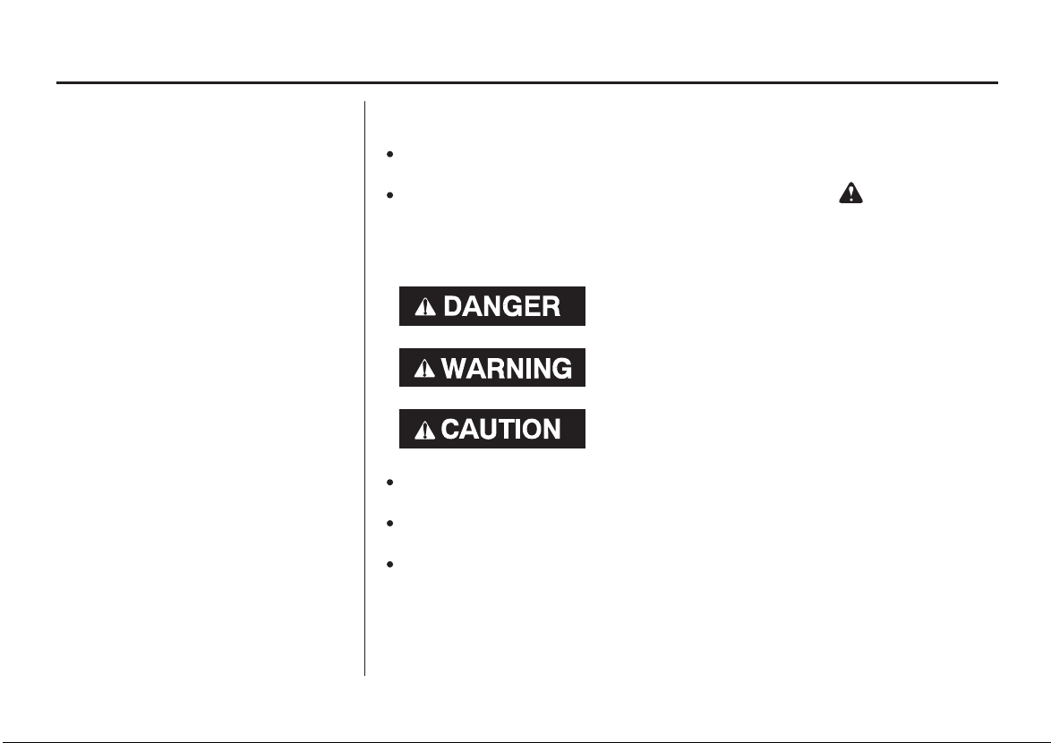
You will find important safety information in a variety of forms, including:
Safety Labels
Safety Messages
three signal words, DANGER, WARNING, or CAUTION.
These signal words mean:
Safety Headings
Safety Section
Instructions
This entire book is filled with important saf ety information please read it
carefully.
−
on the outboard motor.
−
preceded by a safety alert symbol and one of
You WILL be KILLED or SERIOUSLY
HURT if you don’t follow instructions.
You CAN be KILLED or SERIOUSLY
HURT if you don’t follow instructions.
You CAN be HURT if you don’t follow
instructions.
−
such as
−
such as
−
how to use this outboard motor correctly and safely.
IMPORTANT SAFETY INFORMATION.
OUTBOARD MOTOR SAFETY.
−
2

CONTENTS
...................................OUTBOARD MOTOR SAFETY . 7
................................SAFETY LABEL LOCATIONS . 9
..................................CONTROLS AND FEATURES . 10
CONTROL AND FEATURE
................................IDENTIFICATION CODES . 10
..............................................................CONTROLS . 16
LH and LHT Types (long tiller handle)
......................................................Ignition Switch . 16
..........................................................Throttle Grip . 17
.....................................Throttle Friction Adjuster . 18
.....................................................Gearshift Lever . 18
.....................................Steering Friction Adjuster . 18
..........................Tilt Lever (gas assisted/LH type) . 19
LRT and XRT Types (remote control)
........................Ignition Switch (side-mount type) . 19
Switch Clip and Emergency Stop Switch
..............................................(side-mount type) . 20
.........................Fast Idle Lever (side-mount type) . 21
Gearshift/Throttle Control Lever
..............................................(side-mount type) . 21
................IMPORTANT SAFETY INFORMATION . 7
....COMPONENT AND CONTROL LOCATIONS . 11
.............Emergency Stop Switch and Switch Clip . 16
Common Controls
Power Trim/Tilt Switch (LRT and XRT types)
..............................................(side-mount type) . 23
...Power Tilt Switch (LHT, LRT and XRT types) . 23
Manual Relief Valve
.............................(LHT, LRT and XRT types) . 24
.....................................................Tilt Lock Lever . 24
...........................................Engine Cover Latches . 24
.............................Transom Angle Adjusting Rod . 25
................................................................Trim Tab . 25
.......................................................INSTRUMENTS . 26
.........................Trim Meter (optional equipment) . 26
.........................Tachometer (optional equipment) . 26
.........................Fuel Gauge (optional equipment) . 26
...........................................................INDICATORS . 27
............................................Oil Pressure Indicator . 27
...........................................Overheating Indicator . 28
.....................................Cooling System Indicator . 29
3

CONTENTS
................................................OTHER FEATURES . 29
.....................................................Overrev Limiter . 29
...................................................................Anodes . 29
.................................................Fuel Priming Bulb . 31
................................................BEFORE OPERATION . 32
IS YOUR OUTBOARD MOTOR
?
................................................READY TO GO . 32
................................................................OPERATION . 34
.......................................BREAK-IN PROCEDURE . 34
................................FUEL HOSE CONNECTIONS . 36
.......................................................FUEL PRIMING . 37
.............Portable Fuel Tank (optional equipment) . 30
..........Fuel Cap Vent Knob (optional equipment) . 30
?
.....ARE YOU READY TO GET UNDER WAY . 32
....................SAFE OPERATING PRECAUTIONS . 34
.....................TRANSOM ANGLE ADJUSTMENT . 35
....PORTABLE FUEL TANK (optional equipment) . 36
......................................STARTING THE ENGINE . 37
................LH and LHT Types (long tiller handle) . 37
.................LRT and XRT Types (remote control) . 39
.....................................EMERGENCY STARTING . 42
.......................................STOPPING THE ENGINE . 45
................................Emergency Engine Stopping . 45
.......................................Normal Engine Stopping . 45
GEARSHIFTING AND
..............................THROTTLE OPERATION . 47
................LH and LHT Types (long tiller handle) . 47
.................LRT and XRT Types (remote control) . 48
...............................................................STEERING . 49
................LH and LHT Types (long tiller handle) . 49
.................LRT and XRT Types (remote control) . 49
................................................................CRUISING . 50
................................................................TRIM TAB . 52
......................SHALLOW WATER OPERATIONS . 52
...............MOORING, BEACHING, LAUNCHING . 54
4

CONTENTS
.....................................MAINTENANCE SAFETY . 57
TOOL KIT (optional equipment) AND
...............................MAINTENANCE SCHEDULE . 59
....................................TRIM TAB ADJUSTMENT . 61
....................................MANUAL RELIEF VALVE . 62
ENGINE COVER REMOVAL AND
.............................................INSTALLATION . 62
........................................Engine Oil Level Check . 63
................................................Engine Oil Change . 64
..............................Engine Oil Recommendations . 66
.................................................Lubrication Points . 67
................................................Spark Plug Service . 68
.............................................................REFUELING . 70
...............................FUEL RECOMMENDATIONS . 71
Portable Fuel Tank and Filter Cleaning
.........................................(optional equipment) . 74
..............................................Anode Replacement . 75
..........................................Propeller Replacement . 76
..............SERVICING YOUR OUTBOARD MOTOR . 56
...........THE IMPORTANCE OF MAINTENANCE . 56
.......................EMERGENCY STARTER ROPE . 58
.....Fuel Pump Filter Inspection and Replacement . 72
....................................................................STORAGE . 77
...................................STORAGE PREPARATION . 77
..........................................Cleaning and Flushing . 77
........................................................................Fuel . 80
.............................................................Engine Oil . 81
...................................STORAGE PRECAUTIONS . 82
...............................REMOVAL FROM STORAGE . 82
........................................................TRANSPORTING . 83
WITH OUTBOARD MOTOR INSTALLED
.............................................................ON BOAT . 83
WITH OUTBOARD MOTOR REMOVED
.......................................................FROM BOAT . 83
TAKING CARE OF UNEXPECTED
..........................................................PROBLEMS . 84
BATTERY WILL NOT CHARGE AND
.ELECTRIC STARTER WILL NOT OPERATE . 89
OIL PRESSURE INDICATOR LIGHT GOES OFF
...................AND ENGINE SPEED IS LIMITED . 90
OVERHEATING INDICATOR LIGHT COMES
............ON AND ENGINE SPEED IS LIMITED . 91
..........................................SUBMERGED MOTOR . 92
5

CONTENTS
...............................TECHNICAL INFORMATION . 94
......................................Serial Number Locations . 94
Carburetor Modification for High Altitude
...........................................................Operation . 95
...................................................................Battery . 95
..................................................Oxygenated Fuels . 96
..............................................................Star Label . 99
......................................................Specifications . 101
.............................CONSUMER INFORMATION . 103
.........................................................................INDEX . 104
........................WIRING DIAGRAMS . Inside Back Cover
..TECHNICAL AND CONSUMER INFORMATION . 94
.................Emission Control System Information . 97
6

OUTBOARD MOTOR SAFETY
IMPORTANT SAFETY INFORMATION
Honda BF40A and BF50A outboard
motors are designed for use with
boats that have a suitable
manufacturer’s power
recommendation. Other uses can
result in injury to the operator or
damage to the outboard motor and
other property.
Most accidents can be prevented if
you follow all instructions in this
manual and on the outboard motor.
The most common hazards are
discussed below, along with the best
way to protect yourself and others.
Operator Responsibility
It is the operator’s responsibility to
provide the necessary safeguards
to protect people and property.
Know how to stop the engine
quickly in case of emergency.
Understand the use of all controls.
Stop the engine immediately if
anyone falls overboard, and do not
run the engine while the boat is
near anyone in the water.
Always stop the engine if you
must leave the controls for any
reason.
Attach the emergency stop switch
lanyard securely to the operator.
Always wear a PFD (Personal
Flotation Device) while on the
boat.
Familiarize yourself with all laws
and regulations relating to boating
and the use of outboard motors.
Be sure that anyone who operates
the outboard motor receives proper
instruction.
Be sure the outboard motor is
properly mounted on the boat.
Do not remove the engine cover
while the engine is running.
7

OUTBOARD MOTOR SAFETY
Carbon Monoxide HazardRefuel With Care
Gasoline is extremely flammable,
and gasoline vapor can explode.
Refuel outdoors, in a wellventilated area, with the engine
stopped. Never smoke near
gasoline, and keep other flames
and sparks away.
Remove any portable fuel tank
from the boat for refueling. Keep
the portable fuel tank away from
the battery or other potential spark
sources.
Refuel carefully to avoid spilling
fuel. Avoid overfilling the fuel
tank.
After refueling, tighten the filler
cap securely. If any fuel is spilled,
make sure the area is dry before
starting the engine.
Exhaust gas contains poisonous
carbon monoxide. Avoid inhalation
of exhaust gas. Never run the engine
in a closed garage or confined area.
8
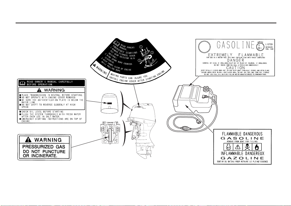
SAFETY LABEL LOCATIONS
OUTBOARD MOTOR SAFETY
The labels shown here contain important safety information. Please read them carefully. These labels are considered
permanent parts of your outboard motor. If a label comes off or becomes hard to read, contact an authorized Honda
Marine servicing dealer for a replacement.
9
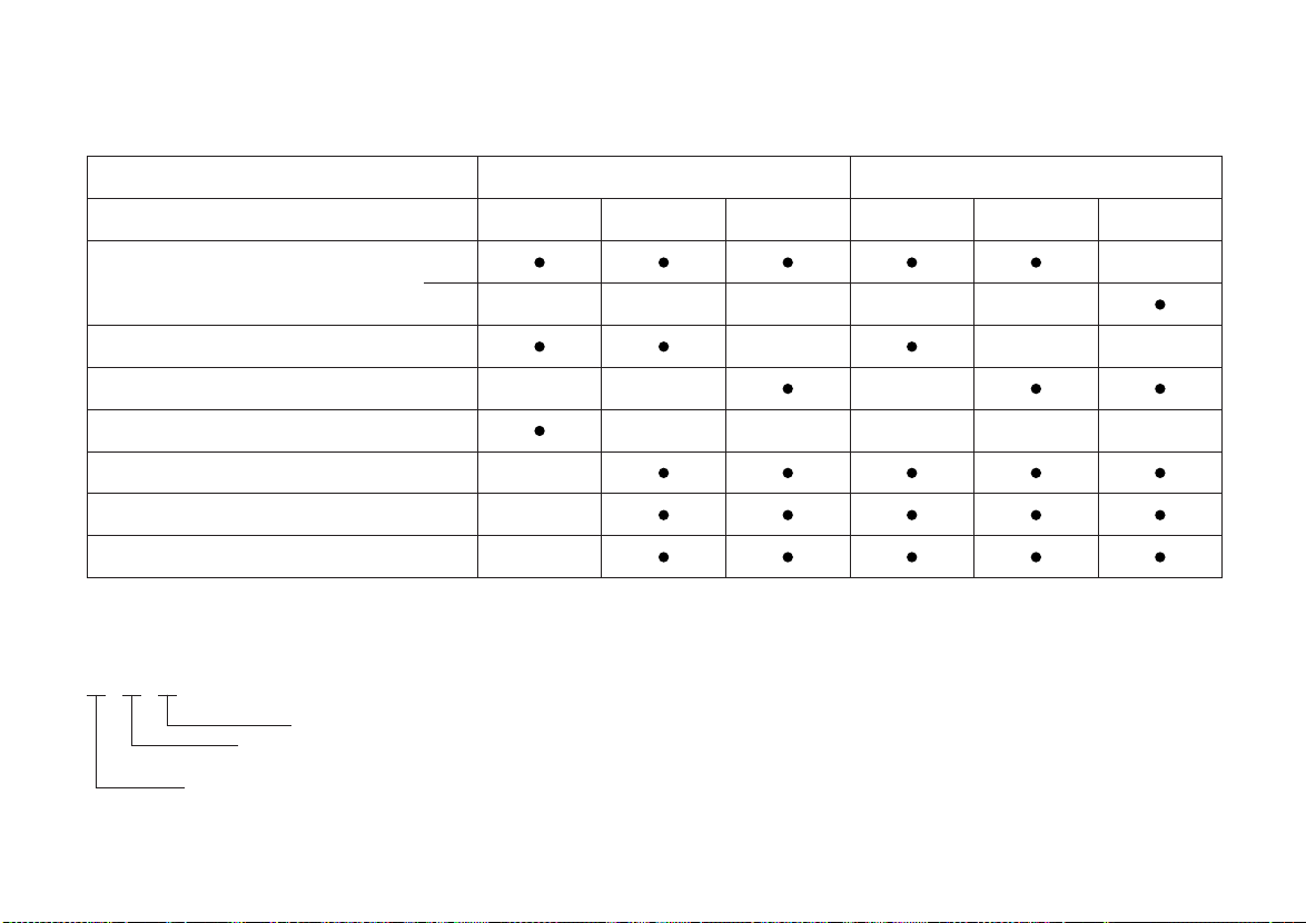
CONTROLS AND FEATURES
CONTROL AND FEATURE IDENTIFICATION CODES
Model
Type
Shaft Length
Long Tiller Handle
Remote Control
Gas Assisted Tilt
Power Trim/Tilt
Tachometer (optional equipment)
Trim Meter (optional equipment)
Refer to this chart for an explanation of the Type Codes used in this manual to identify control and feature applications.
TYPE CODE (Example)
L
RT
T=Power Trim/Tilt
H=Long Tiller Handle
R=Remote Control
L=Long Shaft
X=Extra Long Shaft
L
X
BF40A BF50A
XRTLRTLHTLRTLHTLH
10
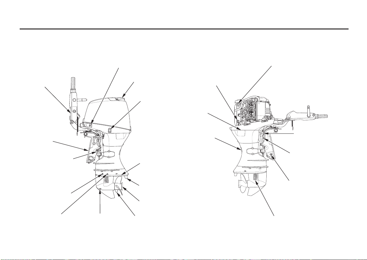
COMPONENT AND CONTROL LOCATIONS
LH and LHT Types
(long tiller handle)
FUEL HOSE CONNECTOR
CONTROLS AND FEATURES
OIL FILLER CAP
LONG TILLER
HANDLE
STERN
BRACKET
TRANSOM ANGLE
ADJUSTING ROD
GEAR OIL LEVEL
CHECK PLUG
WASH PLUG
(Flush plug)
GEAR OIL
DRAIN PLUG
ENGINE COVER
POWER TILT
SWITCH
(LHT type)
ANTIVENTILATION
PLATE
TRIM TAB (anode)
EXHAUST PORT
PROPELLER
(optional equipment)
OIL LEVEL
DIPSTICK
COOLING
SYSTEM
INDICATOR
ENGINE OIL
DRAIN PLUG
COVER
TILT LOCK LEVER
TILT LEVER
(LH type)
MANUAL RELIEF VALVE
(LHT Type)
WATER INTAKE
11
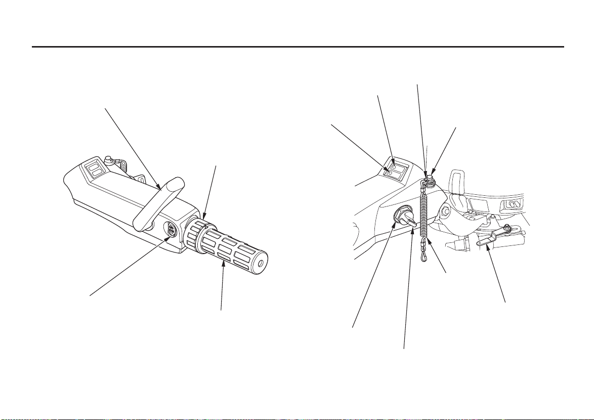
CONTROLS AND FEATURES
GEAR SHIFT
THROTTLE FRICTION ADJUSTER
POWER TRIM/TILT SWITCH
(LHT type)
THROTTLE GRIP
OIL PRESSURE
INDICATOR LIGHT
OVERHEAT
INDICATOR LIGHT
IGNITION SWITCH
SWITCH CLIP
EMERGENCY STOP SWITCH
LANYARD
STEERING FRICTION ADJUSTER
IGNITION SWITCH KEY
12
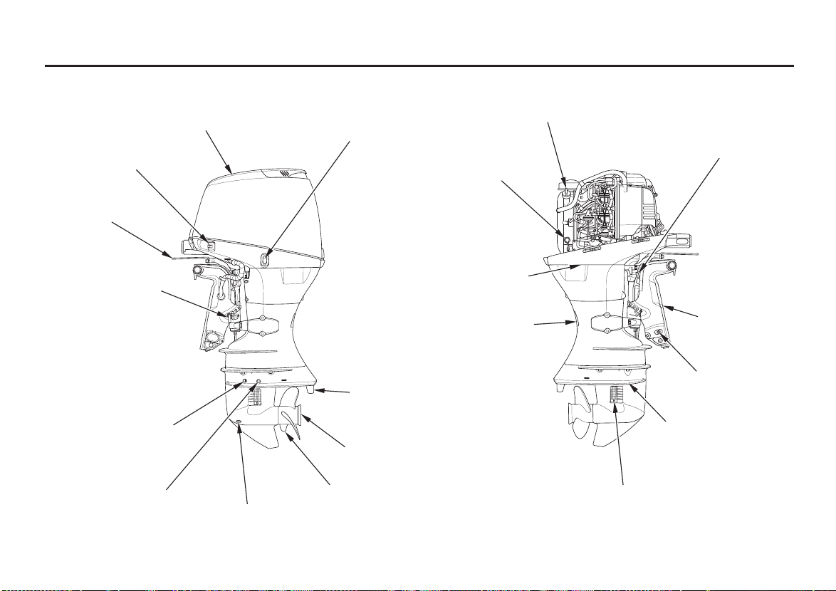
LRT and XRT Types (remote control)
CONTROLS AND FEATURES
FUEL HOSE
CONNECTOR
STEERING
PLATE
TRANSOM ANGLE
ADJUSTING ROD
GEAR OIL LEVEL
CHECK PLUG
WASH PLUG
(Flush plug)
ENGINE COVER
GEAR OIL
DRAIN PLUG
POWER TILT SWITCH
COOLING SYSTEM
INDICATOR
ENGINE OIL DRAIN
PLUG COVER
TRIM TAB
(anode)
EXHAUST PORT
PROPELLER
(optional equipment)
OIL FILLER CAP
OIL LEVEL
DIPSTICK
TILT LOCK LEVER
STERN
BRACKET
MANUAL RELIEF
VALVE
ANTIVENTILATION
PLATE
WATER INTAKE
13
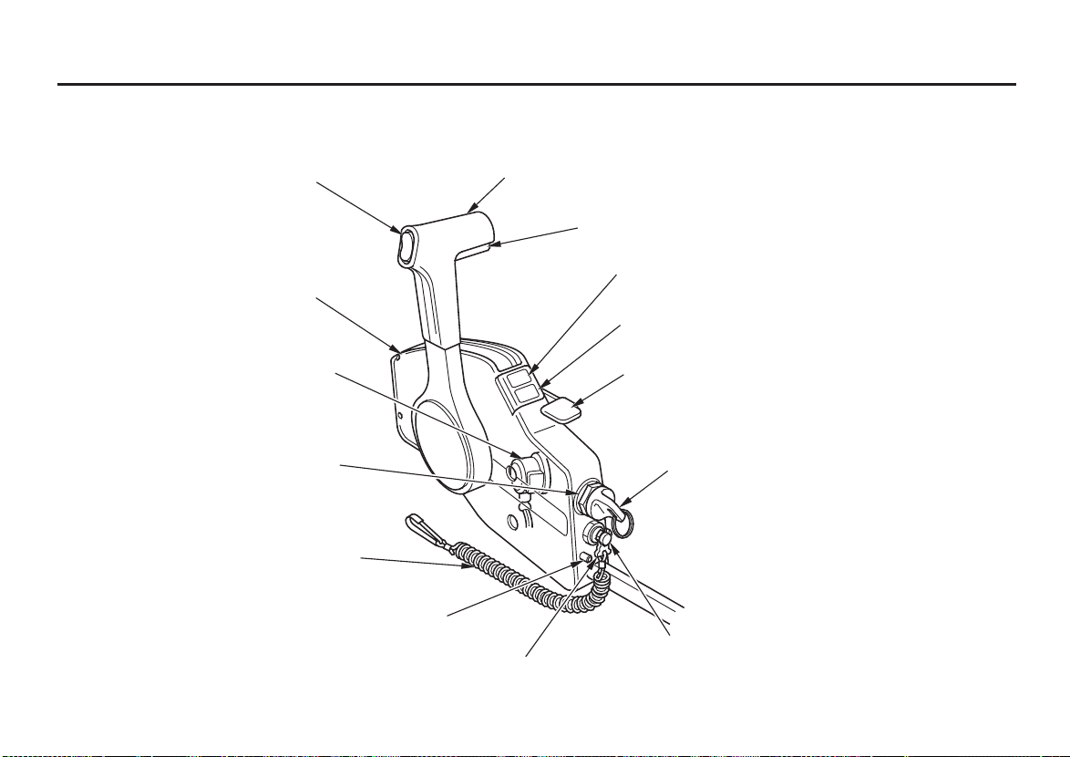
CONTROLS AND FEATURES
Remote Control box (side mount type/optional equipment)
GEARSHIFT/THROTTLE
POWER TRIM/TILT SWITCH
SPARE SWITCH CLIP
CONTROL LEVER
NEUTRAL RELEASE LEVER
OIL PRESSURE INDICATOR LIGHT
OVERHEAT INDICATOR LIGHT
14
BUZZER (inside of the box)
IGNITION SWITCH
LANYARD
THROTTLE FRICTION ADJUSTER
FAST IDLE LEVER
IGNITION SWITCH KEY
EMERGENCY STOP SWITCH
SWITCH CLIP
CONTROLS AND FEATURES
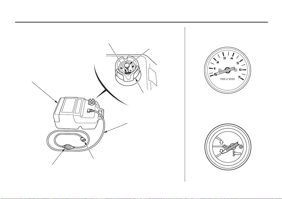
Fuel Tank (optional equipment)
FUEL TANK
PRIMING BULB
Tachometer
(optional equipment)
FUEL GAUGE
VENT KNOB
FUEL CAP
Trim Meter
(optional equipment)
FUEL HOSE
FUEL HOSE CONNECTOR
(female)
15
CONTROLS AND FEATURES
CONTROLS
LH and LHT Types
(long tiller handle)
Ignition Switch
IGNITION SWITCH
ON
START
OFF
The ignition switch controls the
ignition system and starter motor.
Turning the ignition switch key to the
START position operates the starter
motor. The key automatically returns
to the ON position when released
from the START position.
The ignition switch can be used to
operate the starter motor only when
the gearshift lever (p. ) is in the N
18
(neutral) position, and the switch clip
is in the emergency stop switch.
Turning the ignition switch to the
OFF position stops the engine.
Emergency Stop Switch and
Switch Clip
EMERGENCY STOP SWITCH
LANYARD
SWITCH CLIP
SWITCH CLIP
LANYARD
16
CONTROLS AND FEATURES
The switch clip must be inserted in
the engine stop switch in order for
the engine to start and run. The
lanyard should be attached to the
operator’s PFD (Personal Flotation
Device) or worn around the wrist as
shown.
When used as described, the
emergency stop switch and lanyard
system stops the engine if the
operator falls away from the controls.
A spare swtich clip is supplied with
the tool kit (optional equipment).
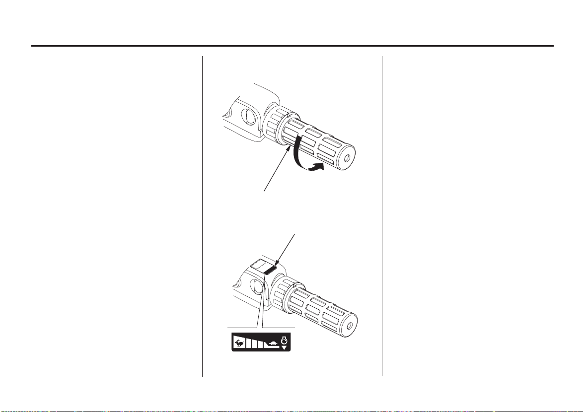
Throttle Grip
THROTTLE GRIP
THROTTLE INDEX MARK
The throttle grip controls engine
speed.
An index mark on the tiller arm
shows throttle position and is helpf ul
for setting the throttle correctly when
starting (p. ).38
INCREASE
17
CONTROLS AND FEATURES
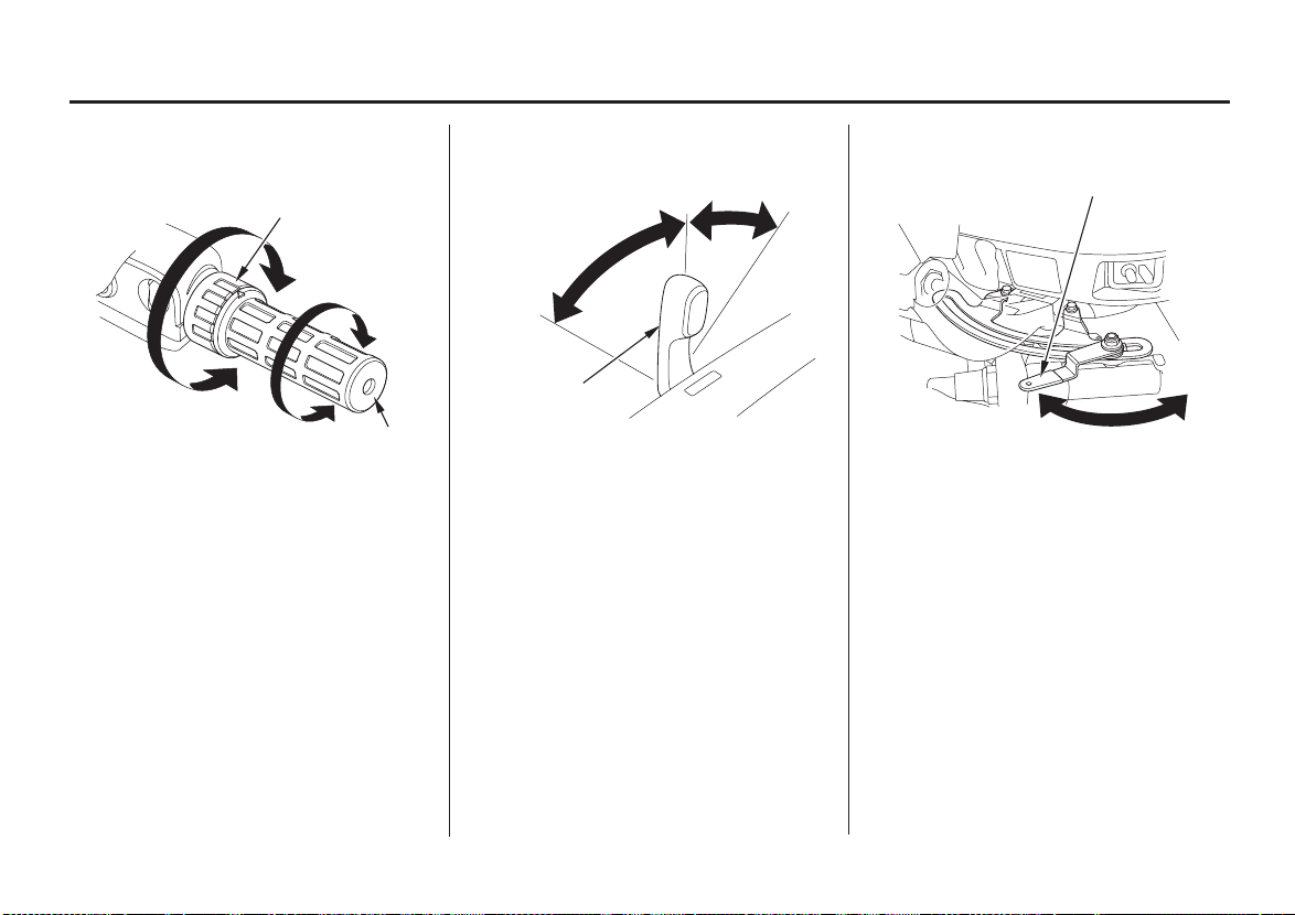
Gearshif t LeverThrottle Friction Adjuster Steering Friction Adjuster
THROTTLE FRICTION
ADJUSTER
FIX
RELEASE
THROTTLE GRIP
The throttle friction adjuster adjusts
resistance to throttle grip rotation.
Turn the adjuster clockwise to
increase friction for holding a throttle
setting while cruising.
Turn the adjuster counterclockwise to
decrease friction for easy throttle grip
rotation.
N (neutral)
F
(forward)
GEARSHIFT
LEVER
R (reverse)
The gearshift lever is used to select F
(forward), N (neutral), or R (reverse)
gears.
The engine can be started with the
gearshift lever in the N (neutral)
position only.
STEERING FRICTION ADJUSTER
LOCK
FREE
The steering friction adjuster adjusts
steering resistance.
Less friction allows the outboard
motor to turn more easily. More
friction helps to hold steady course
while cruising or to prevent the
outboard motor from swinging while
trailering the boat.
18
CONTROLS AND FEATURES
Tilt Lever
(gas assisted/LH type)
FFRREEEE
LLOOCCKK
TILT LEVER
Moving the tilt lever to the FREE
position allows the motor to be tilted
and moving the tilt lever to the
LOCK position locks the motor in
the desired position. Use the tilt lever
to temporarily tilt the motor when the
boat is operating in shallow water, or
mooring in shallow water. The tilt
lever must be in the LOCK position
before operating the motor or the
motor could tilt up when operating in
reverse.
LRT and XRT Types
(remote control/optional
equipment)
For panel-mount or top-mount
remote control information, refer to
the instructions provided with the
remote control equipment.
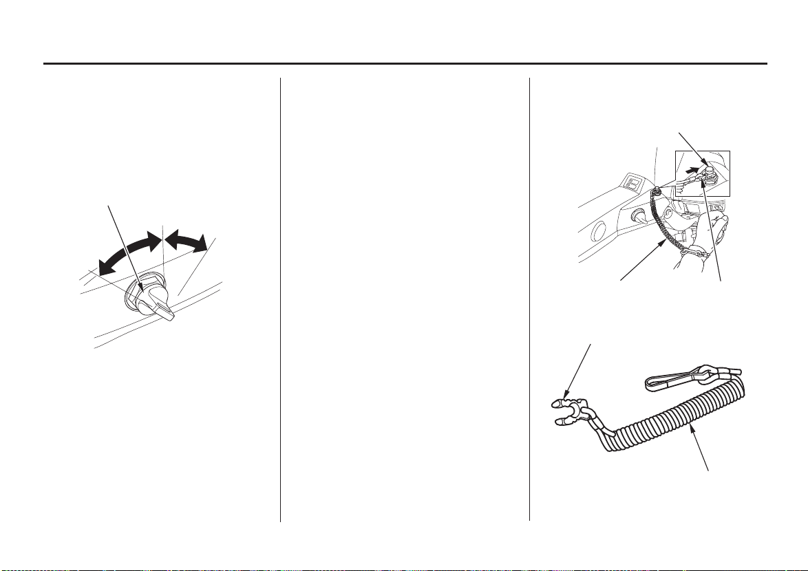
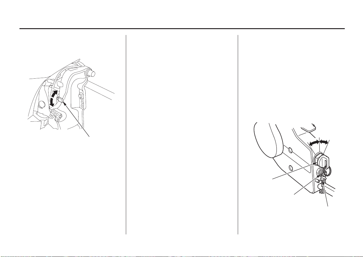
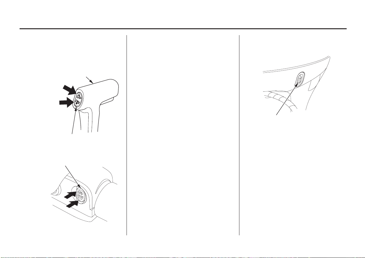
Ignition Switch
(side-mount type)
OONN
OOFFFF
IGNITION
SWITCH
EMERGENCY STOP
SWITCH
SWITCH CLIP
SSTTAARRTT
The ignition switch controls the
ignition system and starter motor.
19
CONTROLS AND FEATURES
Turning the ignition switch key to the
START position operates the starter
motor. The key automatically returns
to the ON position when released
from the START position.
The ignition switch can be used to
operate the starter motor only when
the gearshift lever (p. ) is in the N
18
(neutral) position, and the switch clip
is in the emergency stop switch.
Turning the ignition switch to the
OFF position stops the engine.
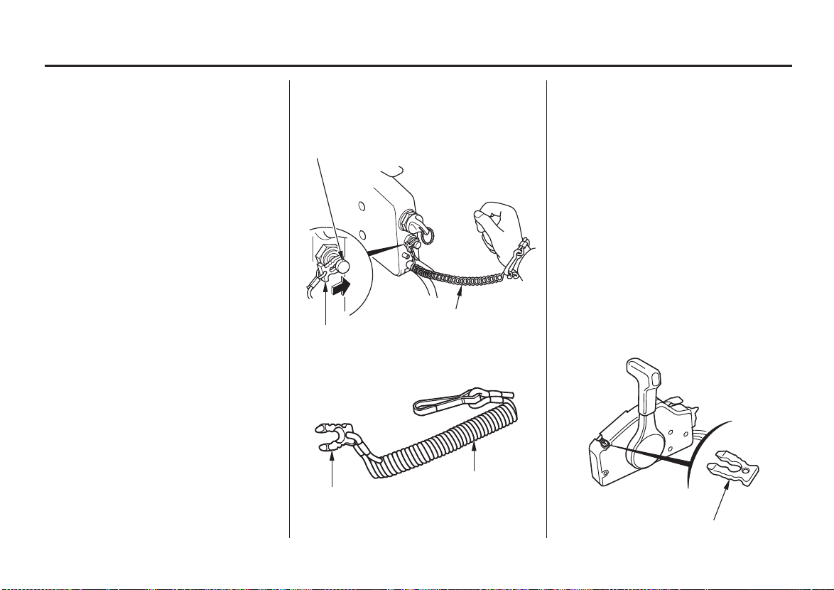
Switch Clip and Emergency Stop
Switch (side-mount type)
EMERGENCY
STOP SWITCH
LANYARD
SWITCH CLIP
LANYARD
SWITCH CLIP
The switch clip must be inserted in
the emergency stop switch in order
for the engine to start and run. The
lanyard must be attached to the
operator’s PFD (Personal Flotation
Device) or worn around the wrist as
shown.
When used as described, the
emergency stop switch and lanyard
system stops the engine if the
operator falls away from the controls.
A spare switch clip is stored in a slot
in the control housing (optional
equipment).
20
SPARE SWITCH CLIP
CONTROLS AND FEATURES
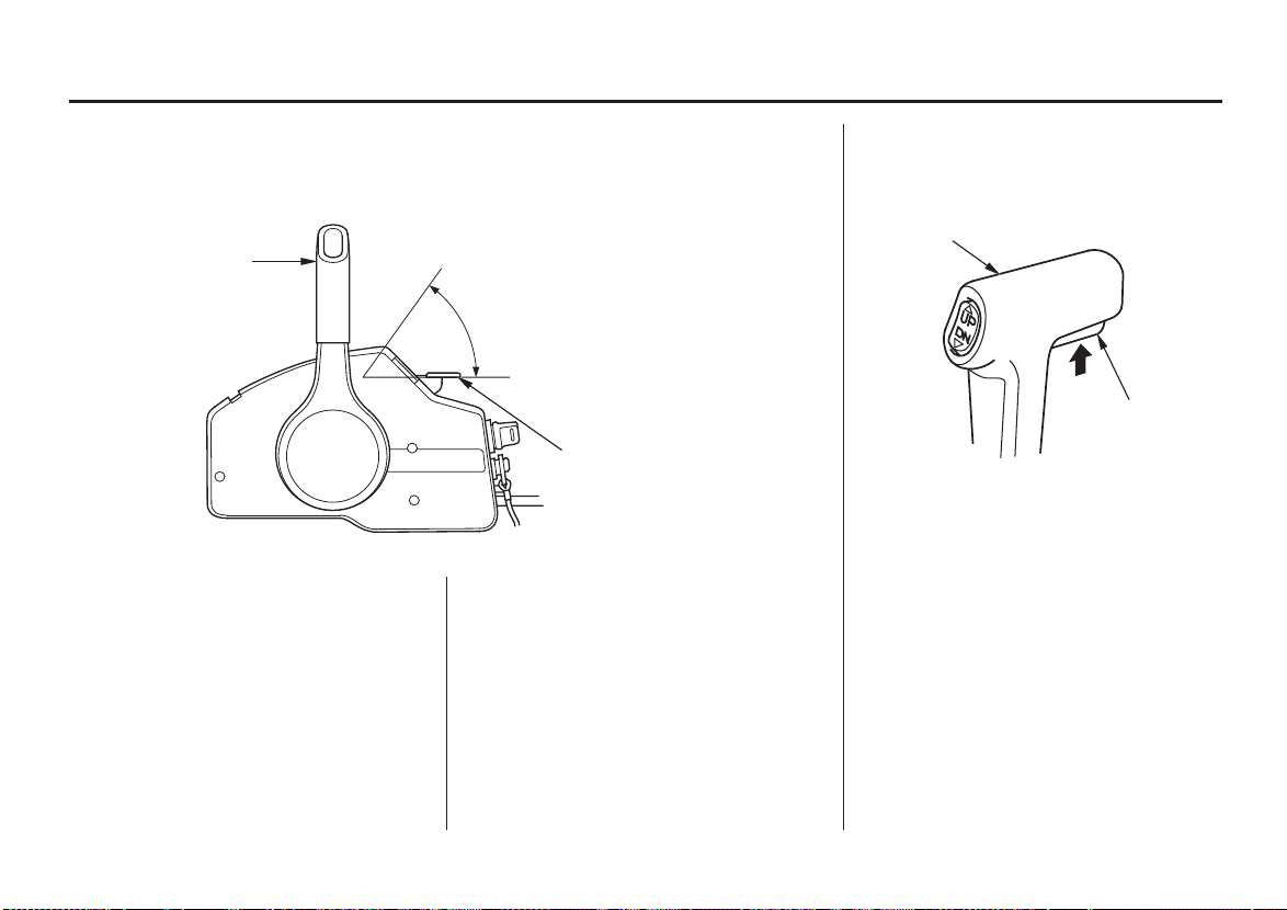
Fast Idle Lever
(side-mount type)
N (neutral)
GEARSHIFT/THROTTLE
CONTROL LEVER
The fast idle lever is used to set idle
speed during warm-up.
The lever will not move unless the
gearshift/throttle control lever is in
the N (neutral) position. Conversely,
the gearshift/throttle control lever
will not move unless the fast idle
lever is in the lowest position.
FAST IDLE
START
FAST IDLE LEVER
Leave the fast idle lever in the
START position to provide a rich
fuel mixture for starting a cold
engine.
Lift the fast idle lever to warm up a
cold engine after starting and to start
a warm engine.
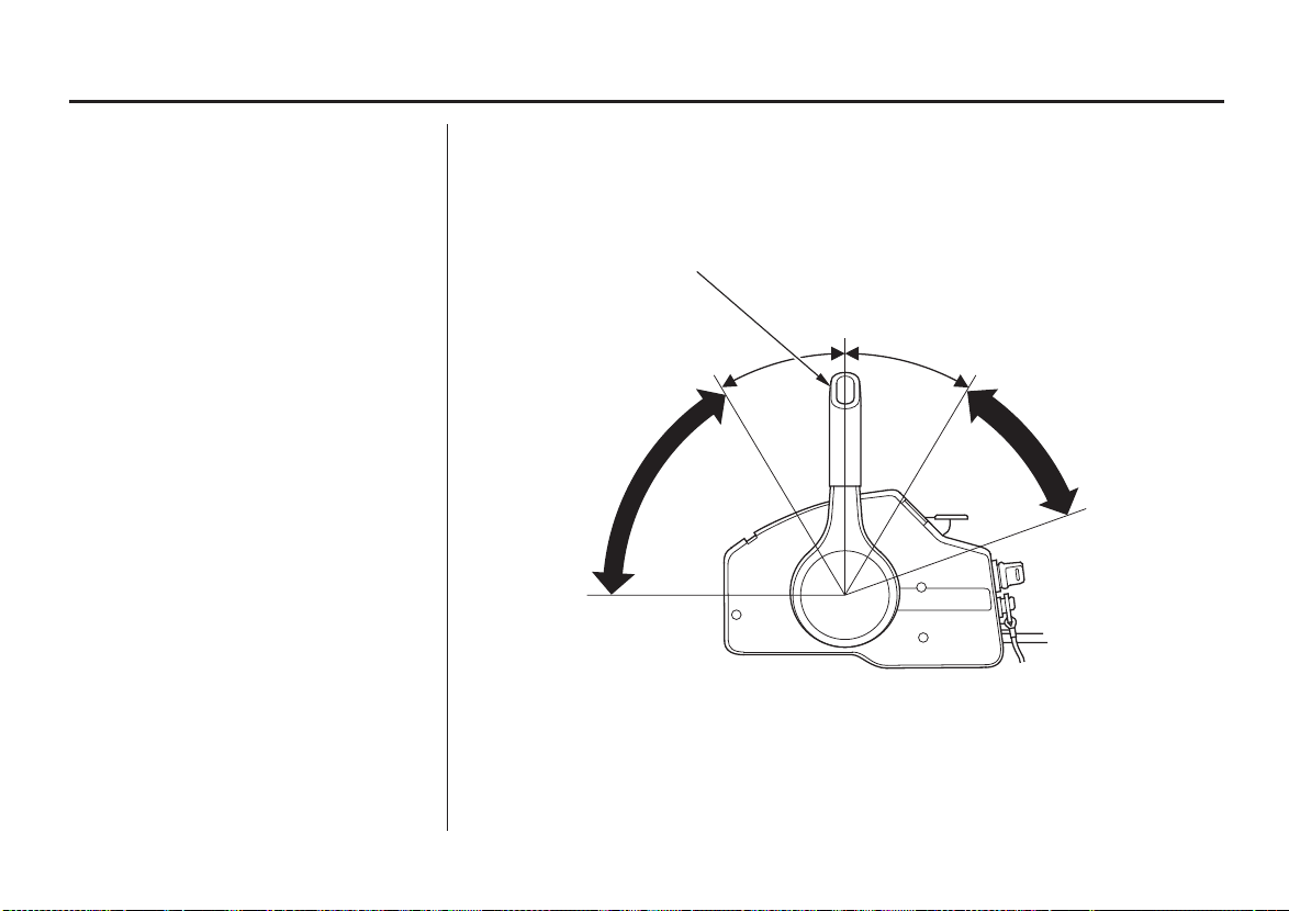
Gearshift/Throttle Control
Lever (side-mount type)
GEARSHIFT/THROTTLE
CONTROL LEVER
NEUTRAL
RELEASE
LEVER
The control lever automatically locks
itself in the N (neutral) position. To
move the lever out of the N (neutral)
position, you must squeeze the
neutral release lever on the underside
of the lever handle.
21
CONTROLS AND FEATURES
The gearshift/throttle control lever
controls engine speed and selects F
(forward), N (neutral), or R (reverse)
gears.
Moving the control lever 30° from N
(neutral) selects the gear, and further
movement increases engine speed.
GEARSHIFT/THROTTLE
CONTROL LEVER
N (neutral)
A friction adjuster near the base of
the control lever adjusts the operating
resistance of the control lever (p. ).
48
Less friction allows easier control
lever movement. More friction helps
to hold a steady throttle setting while
cruising.
22
R (reverse)F(forward)
EENNGGIINNEE
SSPPEEEEDD
EENNGGIINNEE
SSPPEEEEDD
HHIIGGHH
HIGH
CONTROLS AND FEATURES
Common Controls
Power Trim/Tilt Switch
[LRT and XRT types (sidemount type)]
CONTROL LEVER
Press UP to trim
or tilt the motor
up.
Press DN to trim
or tilt the motor
down.
POWER TILT SWITCH
(LHT type)
POWER TRIM/TILT SWITCH
PPrreessss UUPP ttoo ttrriimm oorr
ttiilltt tthhee mmoottoorr uupp..
PPrreessss DDNN ttoo ttrriimm oorr
ttiilltt tthhee mmoottoorr ddoowwnn..
The power trim/tilt switch is located
on the control lever or the tiller
handle. It is a rocker switch with UP
and DN (down) positions for
changing the angle of the outboard
motor.
You can use the power tilt switch
anytime the ignition switch is ON,
whether the boat is underway or
stopped.
Trim the outboard motor to obtain
the best performance and stability
(p. ).
50
Tilt the outboard motor for shallow
water operation, beaching, launching,
or mooring.
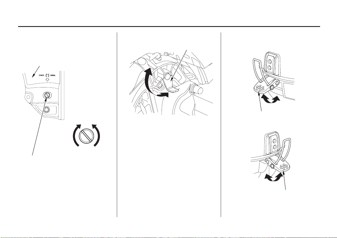
Power Tilt Switch
(LHT, LRT and XRT types)
POWER TILT SWITCH
The power tilt switch is located on
the engine pan. It is a rocker switch
with UP and DN (down) positions
for changing the angle of the
outboard motor.
The power tilt switch will operate
without turning the ignition switch
ON.
This switch is used with the engine
stopped to raise the outboard motor
for mooring, trailering or
maintenance.
23
CONTROLS AND FEATURES
Manual Relief Valve Tilt Lock Lever Engine Cover Latches
(LHT, LRT and XRT types)
TTIILLTT LLOOCCKK LLEEVVEERR
FRONT
RIGHT STERN BRACKET
POWER
(To fix)
MANUAL RELIEF VALVE
MANUAL
(To release)
The outboard motor can be tilted
manually after opening the manual
relief valve. This allows the outboard
motor to be tilted when no battery is
connected.
24
FFRREEEE
LLOOCCKK
The tilt lock lever is used to support
the outboard motor in the fully-raised
position.
When the boat is to be moored for a
long time, tilt the outboard motor as
far as it will go. Then move the tilt
lock lever to the LOCK position, and
gently lower the outboard motor until
the lever contacts the stern bracket.
UNLATCH
ENGINE COVER LATCH
REAR
FFIIXX
ENGINE COVER LATCH
FFIIXX
UNLATCH
The engine cover latches fasten the
engine cover to the outboard motor.
CONTROLS AND FEATURES
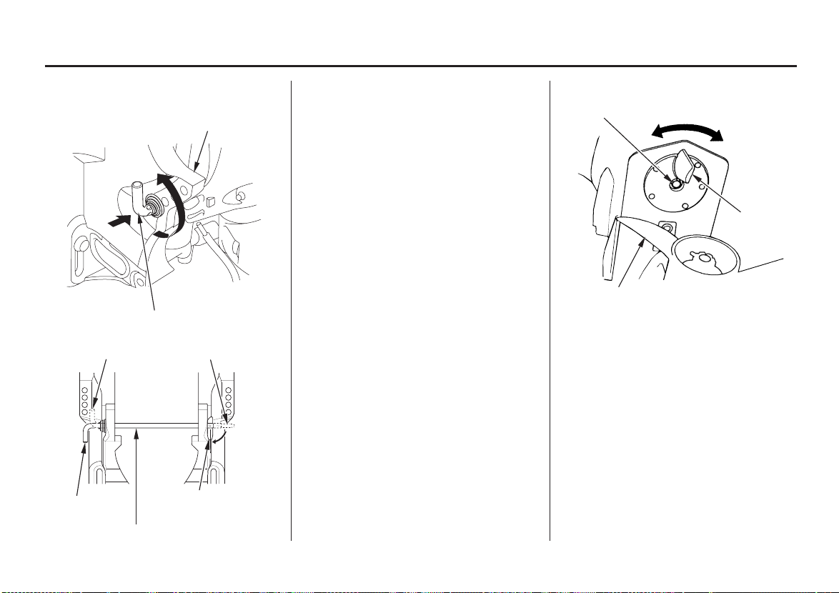
Transom Angle Adjusting Rod Trim Tab
STERN BRACKET
TTUURRNN UUPP
PPUUSSHH
TRANSOM ANGLE ADJUSTING ROD
The transom angle adjusting rod
limits the tilt angle of the outboard
motor when fully lowered.
Proper adjustment prevents the
outboard motor from being trimmed
too low (p. ).
50
TIGHTENING BOLT
PROPELLER
The trim tab compensates for
‘‘torque steer,’’ which is a reaction of
TO CHANGE
UNLOCKED POSITION
the outboard motor to propeller
rotation.
If uncompensated, torque steer would
make the outboard motor tend to turn
to one side.
When the trim tab is correctly
adjusted (p. ), steering effort is
TO LOCK
LOCKED POSITION
equal in either direction.
TRIM TAB
61
TRANSOM ANGLE ADJUSTING ROD
25
CONTROLS AND FEATURES
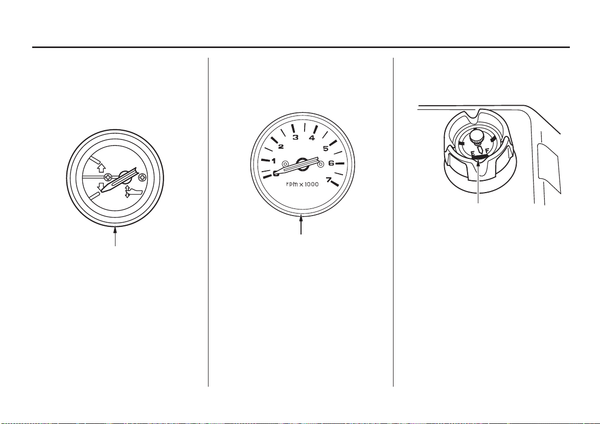
INSTRUMENTS
Trim Meter
[optional equipment (LHT,
LRT and XRT Types)]
TRIM METER
The trim meter has a range of 0° to
16° and indicates the trim angle of
the outboard motor.
Refer to the trim meter when using
the power trim/tilt switch to achieve
proper boat performance.
Tachometer Fuel Gauge
(optional equipment)(optional equipment)
FUEL GAUGE
A fuel gauge is built into the cap of
TACHOMETER
The tachometer shows engine speed
in revolutions per minute.
Refer to the tachometer when using
the throttle and power trim/tilt
controls to achieve the best
performance from the boat.
the portable fuel tank (optional
equipment).
26
CONTROLS AND FEATURES
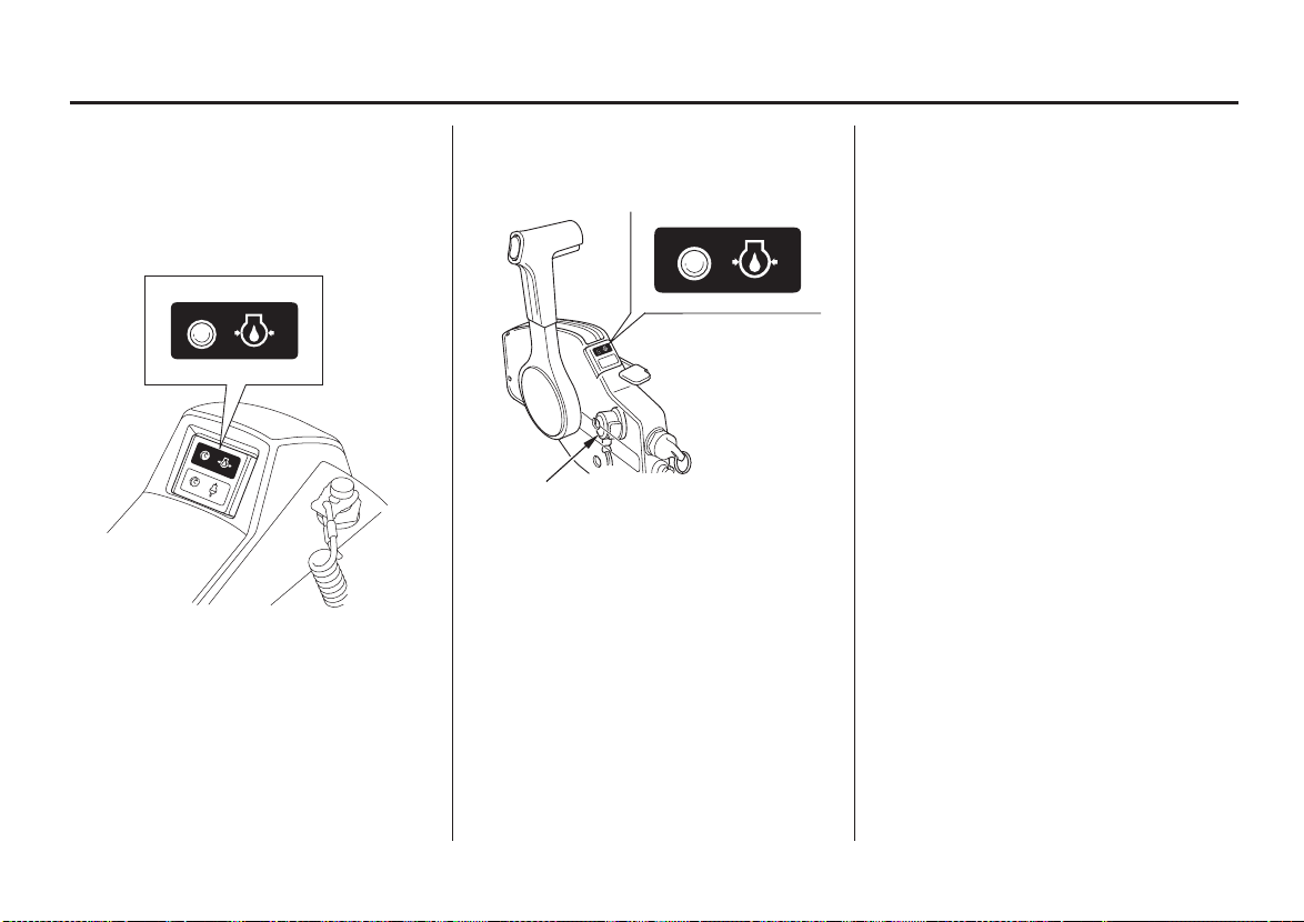
INDICATORS
Oil Pressure Indicator
LH and LHT Types
(GREEN)
LRTandXRTTypes
(side-mount type)
(GREEN)
BUZZER
When the green light is lit, oil
pressure is OK.
If oil pressure becomes low, the
green light will go off, and the
engine protection system will limit
engine speed.
Remote controls are also equipped
with a buzzer that sounds when the
green light goes off.
Low oil pressure indicates that the
engine oil level is low, or that there is
a problem with the engine lubrication
system.
27
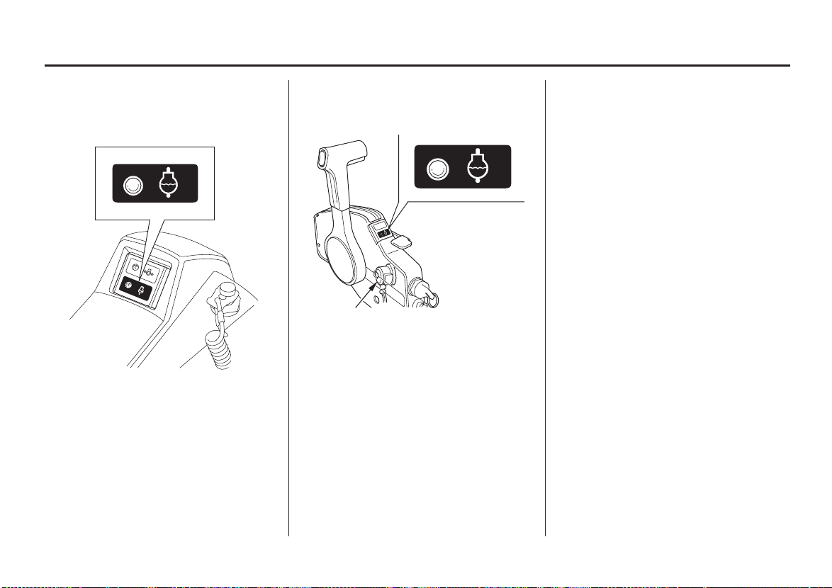
CONTROLS AND FEATURES
Overheating Indicator
LH and LHT Types
(RED)
LRTandXRTTypes
(side-mount type)
BUZZER
(RED)
If the engine overheats, the red light
will come on, and the engine
protection system will limit engine
speed.
Remote controls are also equipped
with a buzzer that sounds when the
red light comes on.
Engine overheating may be the result
of clogged water intakes.
28
 Loading...