

Page 1
BF2D
Owner’s Manual
©2004 Honda Motor Co., Ltd. -All Rights Reserved
2005
Page 2
The engine exhaust from this
product contains chemicals
known to the State of California to
cause cancer, birth defects, or
other reproductive harm.
Keep this owner’s manual handy, so you can refer to it at any time. This owner’s
manual is considered a permanent part of the outboard motor and should remain with
the outboard motor if resold.
The information and specifications included in this publication were in effect at the
time of approval for printing. Honda Motor Co., Ltd. reserves the right, however, to
discontinue or change specifications or design at any time without notice and without
incurring any obligation whatever. No part of this publication may be reproduced
without written permission.
Page 3
INTRODUCTION
Congratulations on your selection of
a Honda outboard motor. We are
certain you will be pleased with your
purchase of one of the finest
outboard motors on the market.
We want to help you get the best
results from your new outboard
motor and to operate it safely. This
manual contains the information on
how to do that; please read it
carefully.
As you read this manual you will
find information preceded by a
symbol. That information
is intended to help you avoid damage
to your outboard motor, other
property, or the environment.
We suggest you read the warranty
policy to fully understand its
coverage and your responsibilities of
ownership.
When your outboard motor needs
scheduled maintenance, keep in mind
that your Honda marine dealer is
specially trained in servicing Honda
outboard motors. Your Honda marine
dealer is dedicated to your
satisfaction and will be pleased to
answer your questions and concerns.
2004 Honda Motor Co., Ltd. All
Rights Reserved
1
Page 4
INTRODUCTION
A FEW WORDS ABOUT
SAFETY
Your safety and the safety of others
are very important. And using this
outboard motor safely is an important
responsibility.
To help you make informed
decisions about safety, we have
provided operating procedures and
other information on labels and in
this manual. This information alerts
you to potential hazards that could
hurt you or others.
Of course, it is not practical or
possible to warn you about all the
hazards associated with operating or
maintaining an outboard motor. You
must use your own good judgment.
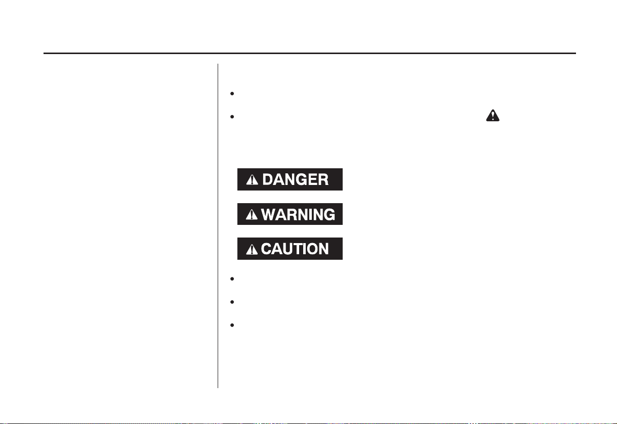
You will find important safety information in a variety of forms, including:
Safety Labels
Safety Messages
three signal words, DANGER, WARNING, or CAUTION.
These signal words mean:
Safety Headings
Safety Section
Instructions
This entire book is filled with important saf ety information please read it
carefully.
−
on the outboard motor.
−
preceded by a safety alert symbol and one of
You WILL be KILLED or SERIOUSLY
HURT if you don’t follow instructions.
You CAN be KILLED or SERIOUSLY
HURT if you don’t follow instructions.
You CAN be HURT if you don’t follow
instructions.
−
such as
−
such as
−
how to use this outboard motor correctly and safely.
IMPORTANT SAFETY INFORMATION.
OUTBOARD MOTOR SAFETY.
−
2
Page 5

CONTENTS
CONTROLS AND FEATURE
..............................................................CONTROLS . 11
.........................................................Choke Knob . 11
Throttle Friction Knob
...................................................Fuel Valve Lever . 13
................................................Recoil Starter Grip . 13
...............................................................Tilt Lever . 14
............................................Steering Friction Bolt . 15
........................................................Clamp Screws . 15
.............................................Fuel Cap Vent Knob . 15
...................................OUTBOARD MOTOR SAFETY . 6
................IMPORTANT SAFETY INFORMATION . 6
................................SAFETY LABEL LOCATIONS . 8
....................................CONTROLS AND FEATURES . 9
..................................IDENTIFICATION CODES . 9
....COMPONENT AND CONTROL LOCATIONS . 10
....................Engine Stop Switch and Switch Clip . 11
................................Throttle lever (SA type only) . 12
..............Throttle Grip (SHA/SCHA/LCHA type) . 12
................................(SHA/SCHA/LCHA type) . 12
.............................Engine Cover Retaining Strap . 13
.............................Transom Angle Adjusting Bolt . 14
................................................OTHER FEATURES . 16
....................................................................Anode . 16
..........................................................INSTALLATION . 17
.....................................POWER REQUIREMENTS . 17
..................................INSTALLATION POSITION . 17
.......................................................ATTACHMENT . 18
................................................BEFORE OPERATION . 20
IS YOUR OUTBOARD MOTOR
?
................................................READY TO GO . 20
..............Centrifugal Clutch (SCHA/LCHA type) . 16
...............................Oil Level Inspection Window . 16
.....................TRANSOM ANGLE ADJUSTMENT . 19
?
.....ARE YOU READY TO GET UNDER WAY . 20
3
Page 6

CONTENTS
................................................................OPERATION . 22
....................SAFE OPERATING PRECAUTIONS . 22
.......................................BREAK-IN PROCEDURE . 22
.....................TRANSOM ANGLE ADJUSTMENT . 22
......................................STARTING THE ENGINE . 23
.....................................EMERGENCY STARTING . 26
.......................................STOPPING THE ENGINE . 28
................................Emergency Engine Stopping . 28
.......................................Normal Engine Stopping . 28
......................................THROTTLE OPERATION . 30
............REVERSING THE OUTBOARD MOTOR . 31
...............................................................STEERING . 32
................................................................CRUISING . 33
...............MOORING, BEACHING, LAUNCHING . 34
..............SERVICING YOUR OUTBOARD MOTOR . 36
...........THE IMPORTANCE OF MAINTENANCE . 36
.....................................MAINTENANCE SAFETY . 37
TOOL KIT AND EMERGENCY STARTER
.....................................................................ROPE . 38
...............................MAINTENANCE SCHEDULE . 39
ENGINE COVER REMOVAL AND
..................................................INSTALLATION . 41
............................................Engine Oil Level Check . 41
....................................................Engine Oil Change . 41
..................................Engine Oil Recommendations . 43
.....................................................Lubrication Points . 44
....................................................Spark Plug Service . 45
.............................................................REFUELING . 47
...............................FUEL RECOMMENDATIONS . 48
.................................Recoil Starter Rope Inspection . 49
..................................................Anode Replacement . 49
..............................................Propeller Replacement . 50
4
Page 7

CONTENTS
....................................................................STORAGE . 51
...................................STORAGE PREPARATION . 51
................................................................Cleaning . 51
........................................................................Fuel . 51
.......................................Adding a Fuel Stabilizer . 52
................Draining the Fuel Tank and Carburetor . 52
.............................................................Engine Oil . 53
...................................STORAGE PRECAUTIONS . 53
...............................REMOVAL FROM STORAGE . 54
........................................................TRANSPORTING . 55
WITH OUTBOARD MOTOR INSTALLED
.............................................................ON BOAT . 55
WITH OUTBOARD MOTOR REMOVED
.......................................................FROM BOAT . 55
..................................ENGINE WILL NOT START . 56
HARD STARTING OR STALLS AFTER
...........................................................STARTING . 58
..........................................SUBMERGED MOTOR . 60
....TAKING CARE OF UNEXPECTED PROBLEMS . 56
..ENGINE WILL NOT DRIVE THE PROPELLER . 59
...............................TECHNICAL INFORMATION . 62
......................................Serial Number Locations . 62
Carburetor Modification for High Altitude
...........................................................Operation . 63
..................................................Oxygenated Fuels . 64
.................Emission Control System Information . 65
..............................................................Star Label . 67
........................................................Specifications . 69
...............................CONSUMER INFORMATION . 70
...............................................Honda Publications . 70
..............................Customer Service Information . 70
−
....................................................WIRING DIAGRAM . 75
...........................................................................INDEX . 76
................Distributors Limited Warranty 2005 . 71
.....................Emission Control System Warranty . 73
..TECHNICAL AND CONSUMER INFORMATION . 62
5
Page 8

OUTBOARD MOTOR SAFETY
IMPORTANT SAFETY INFORMATION
Honda BF2D outboard motor is
designed for use with boats that have
a suitable manufacturer’s power
recommendation. Other uses can
result in injury to the operator or
damage to the outboard motor and
other property.
Most accidents can be prevented if
you follow all instructions in this
manual and on the outboard motor.
The most common hazards are
discussed below, along with the best
way to protect yourself and others.
Operator Responsibility
It is the operator’s responsibility to
provide the necessary safeguards
to protect people and property.
Know how to stop the engine
quickly in case of emergency.
Understand the use of all controls.
Stop the engine immediately if
anyone falls overboard, and do not
run the engine while the boat is
near anyone in the water.
Always stop the engine if you
must leave the controls for any
reason.
Attach the emergency stop switch
lanyard securely to the operator.
Always wear a PFD (Personal
Flotation Device) while on the
boat.
Familiarize yourself with all laws
and regulations relating to boating
and the use of outboard motors.
Be sure that anyone who operates
the outboard motor receives proper
instruction.
Be sure the outboard motor is
properly mounted on the boat.
Do not remove the engine cover
while the engine is running.
6
Page 9

OUTBOARD MOTOR SAFETY
Carbon Monoxide HazardRefuel With Care
Gasoline is extremely flammable,
and gasoline vapor can explode.
Refuel outdoors, in a wellventilated area, with the engine
stopped. Never smoke near
gasoline, and keep other flames
and sparks away.
Refuel carefully to avoid spilling
fuel. Avoid overfilling the fuel
tank.
After refueling, tighten the filler
cap securely. If any fuel is spilled,
make sure the area is dry before
starting the engine.
Exhaust gas contains poisonous
carbon monoxide. Avoid inhalation
of exhaust gas. Never run the engine
in a closed garage or confined area.
7
Page 10
OUTBOARD MOTOR SAFETY
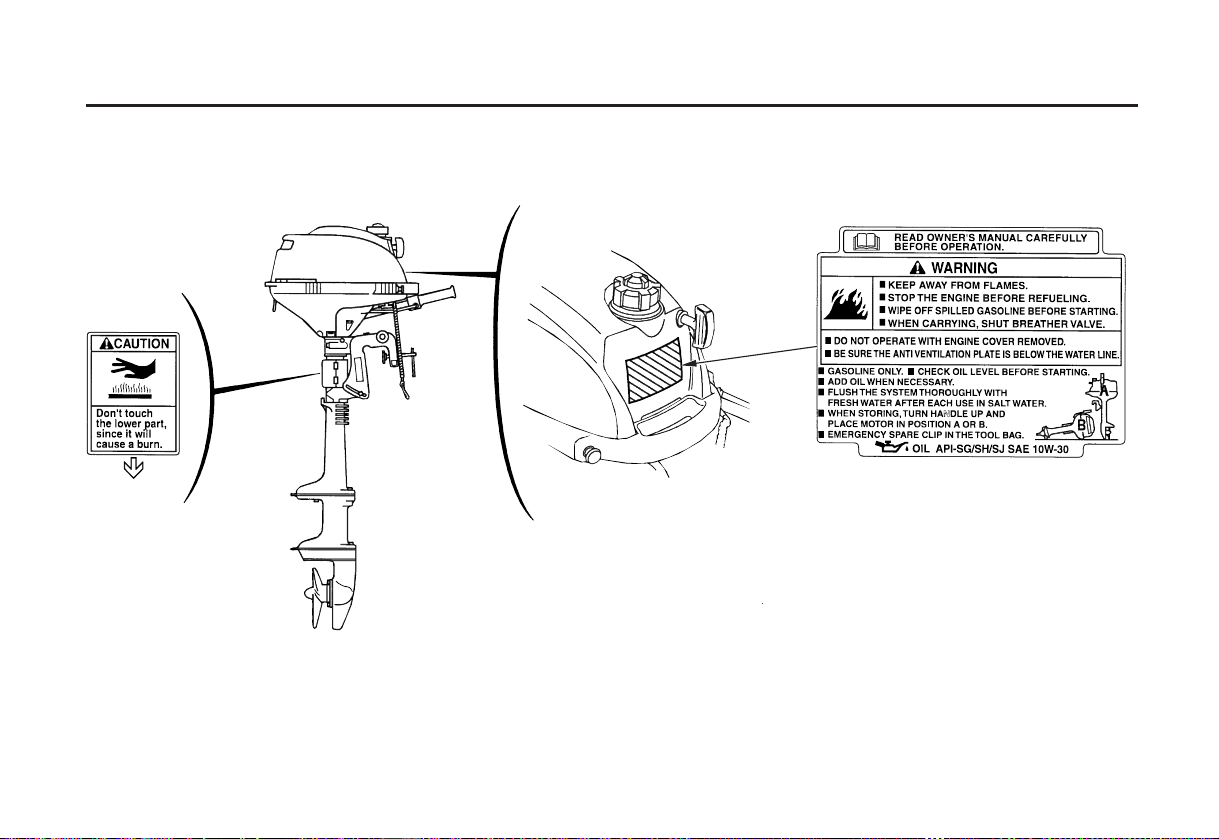
SAFETY LABEL LOCATIONS
The labels shown here contain important safety information. Please read them carefully. These labels are considered
permanent parts of your outboard motor. If a label comes off or becomes hard to read, contact an authorized Honda
Marine servicing dealer for a replacement.
8
Page 11

CONTROL AND FEATURE IDENTIFICATION CODES
CONTROLS AND FEATURES
Model
Type
Shaft Length
Throttle Lever
Throttle Grip
Centrifugal Clutch
Refer to this chart for an explanation of the Type Codes used in this manual to identify control and feature applications.
TYPE CODE(example)
SCH
A
Destination
A=America
Throttle type
H=Throttle grip
None=Throttle lever
Centrifugal clutch
C=With centrifugal clutch
None=Without centrifugal clutch
Shaft length
S=Short shaft
L=Long shaft
S
L
SA SHA SCHA LCHA
BF2D
9
Page 12
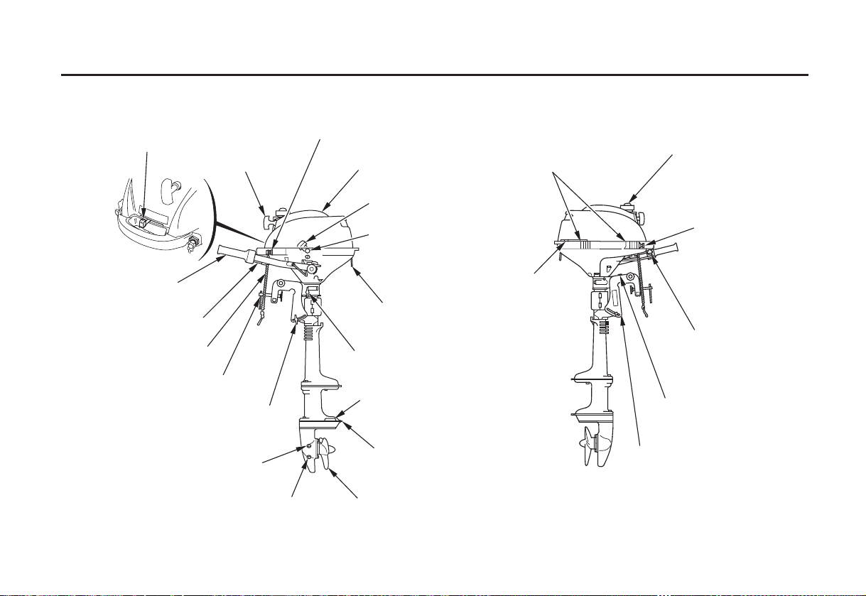
CONTROLS AND FEATURES
COMPONENT AND CONTROL LOCATIONS
THROTTLE LEVER
(SA type only)
STARTER GRIP
THROTTLE GRIP
(SHA/SCHA/LCHA type)
TILLER HANDLE
EMERGENCY ENGINE
STOP SWITCH LANYARD
CLAMP SCREW
TRANSOM ANGLE
ADJUSTING ROD
GEAR OIL LEVEL PLUG
GEAR OIL DRAIN/FILL PLUG
LCHA type is shown
ENGINE STOP SWITCH
ENGINE COVER
OIL FILLER CAP
(inside the engine cover)
OIL LEVEL INSPECTION
WINDOW
ENGINE COVER
RETAINING STRAP
STEERING
FRICTION BOLT
ANODE METAL
ANTIVENTILATION
PLATE
PROPELLER
FUEL FILLER CAP
CASE PROTECTOR
CHOKE KNOB
FUEL VALVE LEVER
THROTTLE GRIP
FRICTION KNOB
(SHA/SCHA/LCHA type)
TILT LEVER
STERN BRACKET
10
Page 13
CONTROLS AND FEATURES
CONTROLS
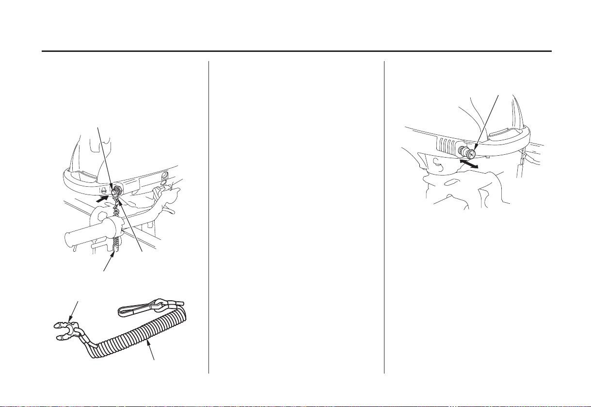
Engine Stop Switch and Switch
Clip
ENGINE STOP SWITCH
SWITCH CLIP
LANYARD
SWITCH CLIP
The engine stop switch controls
normal engine stopping and
emergency engine stopping.
The switch clip must be inserted in
the engine stop switch in order for
the engine to start and run. The
lanyard should be attached to the
operator’s PFD (Personal Flotation
Device) or worn around the wrist as
shown (p. ).23
When used as described, the engine
stop switch and lanyard system stops
the engine if the operator falls away
from the controls.
A spare switch clip is supplied with
the tool kit.
Choke Knob
CHOKE KNOB
OOPPEENN
The choke knob opens and closes the
choke valve in the carburetor.
The CLOSED position enriches the
fuel mixture for starting a cold
engine.
The OPEN position provides the
correct fuel mixture for operation
after starting, and for restarting a
warm engine.
CLOSED
LANYARD
11
Page 14
CONTROLS AND FEATURES
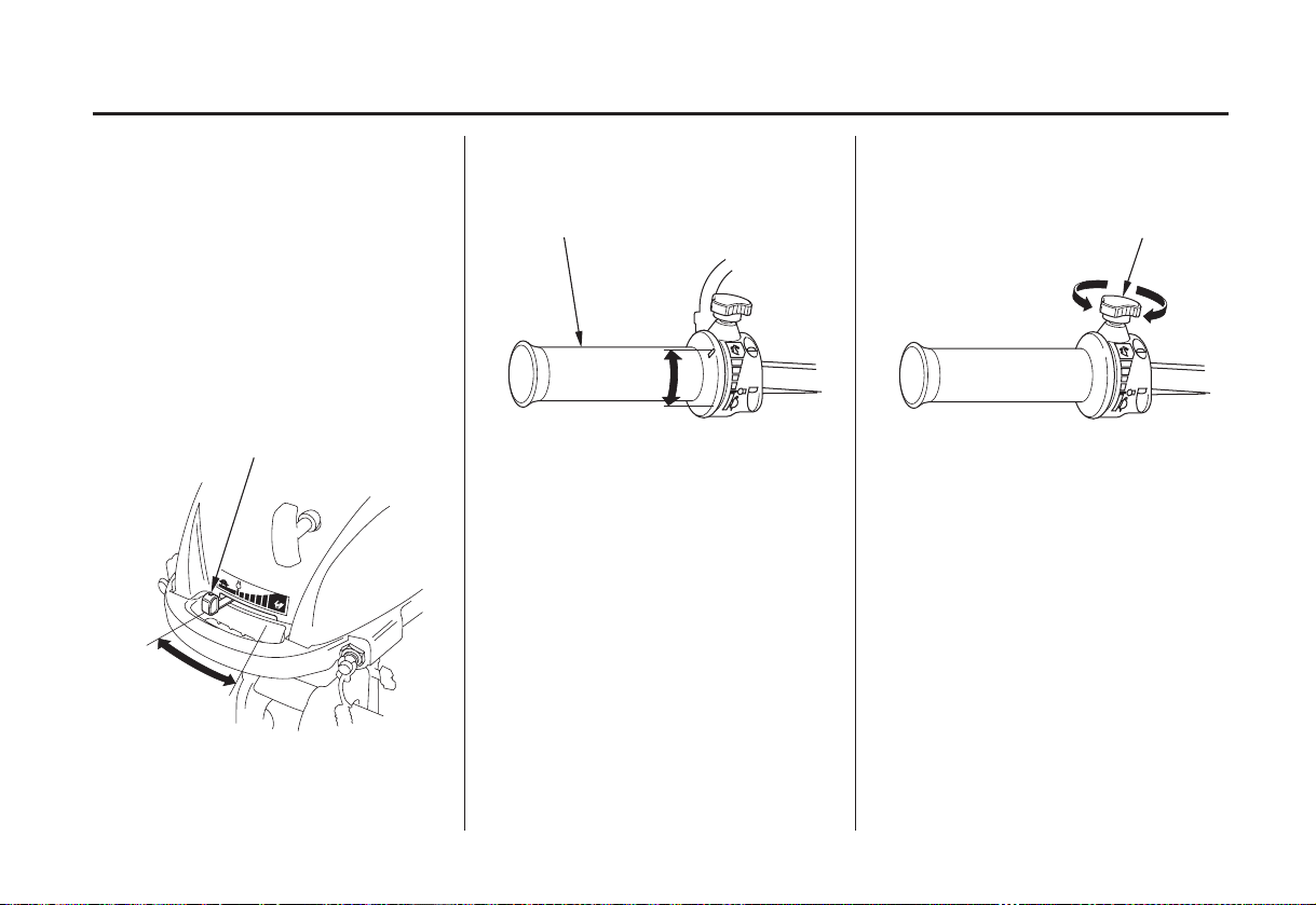
(SHA/SCHA/LCHA type) (SHA/SCHA/LCHA type)
The throttle lever controls engine
speed.
THROTTLE GRIP
Throttle Friction KnobThrottle GripThrottle Lever (SA type only)
THROTTLE GRIP FRICTION KNOB
An index mark on the engine cover
shows throttle position and is helpf ul
for setting the throttle correctly when
starting (p. ).
SLOW
24
THROTTLE LEVER
FAST
12
FAST
SLOW
The throttle grip controls engine
speed.
An index mark on the tiller arm
shows throttle position and is helpf ul
for setting the throttle correctly when
starting (p. ).
24
RELEASE
FIX
The throttle friction knob adjusts
resistance to throttle grip rotation.
Turn the knob clockwise to increase
friction for holding a throttle setting
while cruising.
Turn the knob counterclockwise to
decrease friction for easy throttle grip
rotation.
Page 15
CONTROLS AND FEATURES
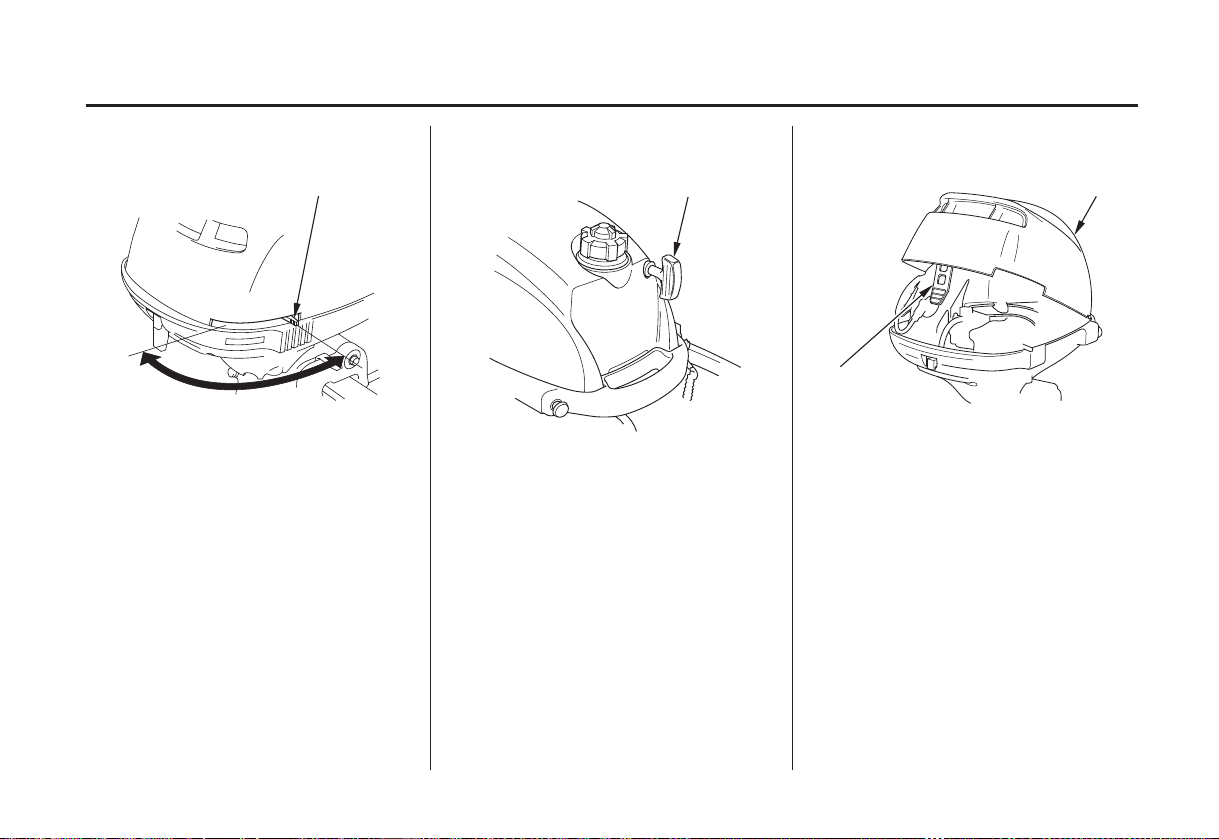
Recoil Starter GripFuel Valve Lever Engine Cover Retaining Strap
FUEL VALVE LEVER ENGINE COVER
ON
OFF
The fuel valve opens and closes the
passage between the fuel tank and the
carburetor.
The fuel valve lever must be in the
ON position for the engine to run.
When the engine is not in use, leave
the fuel valve lever in the OFF
position to prevent carburetor
flooding and to reduce the possibility
of fuel leakage.
RECOIL STARTER GRIP
Pull the starter grip to operate the
recoil starter for starting the engine.
STRAP
Use the retaining strap to hold the
engine cover closed. Do not remove
the engine cover while the engine is
running.
13
Page 16
CONTROLS AND FEATURES
Transom Angle Adjusting Bolt Tilt Lever
FRONT
CARRYING
ADJUSTING BOLT AND WING NUT
HANDLE
REAR CARRYING HANDLE
75°
TILT LEVER
The transom angle adjusting bolt is
used to adjust the angle of the
outboard motor in the normal
operating position (see page ).
22
Loosen the wing nut to free the
adjusting bolt.
Adjust the angle of the outboard
motor, and tighten the wing nut. Be
sure that the bolt head and wing nut
are seated in one of the four recesses
in the adjustment slot.
14
The tilt lever enables the outboard
motor to be tilted for beaching,
launching, or mooring.
Tilt the outboard motor by holding
the carrying handles, as shown. The
spring-loaded tilt lever will
automatically move into position and
hold the outboard motor when it
reaches approximately 75°.
To return the outboard motor to the
normal running position, hold the
outboard motor and pull the tilt lever,
then slowly lower the outboard motor.
Page 17
CONTROLS AND FEATURES
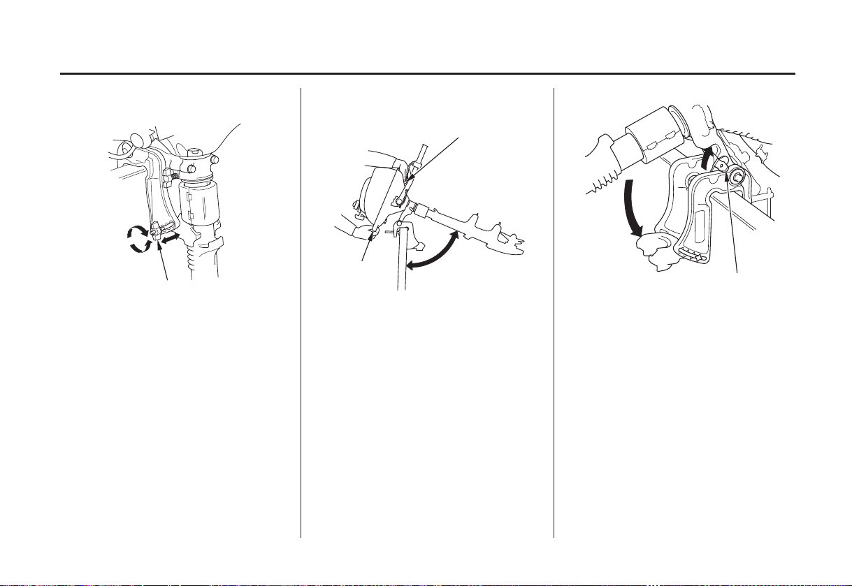
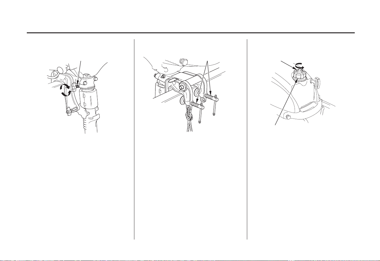
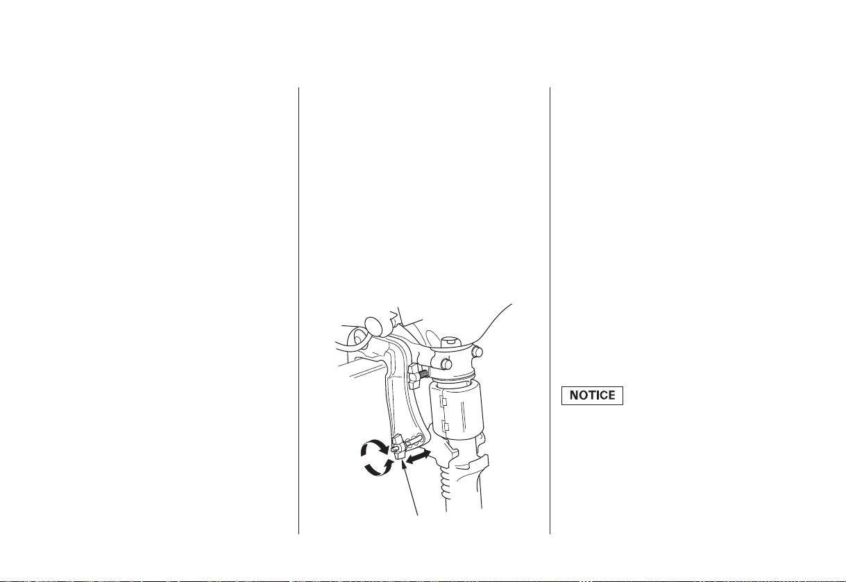
Steering Friction Bolt Clamp Screws Fuel Cap Vent Knob
STEERING FRICTION BOLT
TTOO IINNCCRREEAASSEE
FFRRIICCTTIIOONN
TTOO DDEECCRREEAASSEE
FFRRIICCTTIIOONN
The steering friction bolt adjusts
steering resistance.
Less friction allows the outboard
motor to turn more easily. More
friction helps to hold steady course
while cruising or to prevent the
outboard motor from swinging while
trailering the boat.
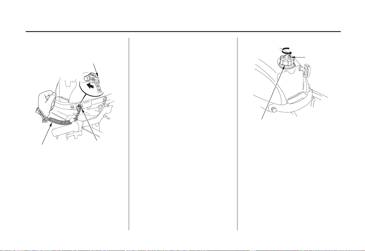
CLAMP SCREWS VENT KNOB
Use the clamp screws to secure the
outboard motor to the transom.
OPEN
FUEL FILLER CAP
The cap is provided with a vent knob
to seal the fuel tank. Open the vent
knob 2 or 3 turns before starting the
engine (p. ).23
15
Page 18
CONTROLS AND FEATURES
Centrifugal Clutch (SCHA/ LCHA type)
The centrifugal clutch automatically
engages and transmits power when
engine speed is increased above
approximately 2,700 rpm. At idle
speed, the clutch is disengaged.
Oil Level Inspection Window
UUPPPPEERR LLIIMMIITT
LLOOWWEERR LLIIMMIITT
OIL LEVEL INSPECTION WINDOW
Use the oil level inspection window
to check the engine oil level with the
engine stopped and the outboard
motor in the upright position.
AnodeOTHER FEATURES
Short shaft type Long shaft type
ANODE
The anode is made of a sacrificial
material that helps to protect the
outboard motor from corrosion.
16
Page 19
INSTALLATION
Correct and secure installation is
essential for safe boating and good
performance. Follow the installation
instructions provided in this manual.
POWER REQUIREMENTS
Before installation, check to be sure
that the outboard motor does not
exceed the recommended maximum
horsepower for the boat on which it
is to be installed. Refer to the boat’s
certification plate for recommended
maximum horsepower. If the
certification plate information is not
available, contact the boat dealer or
manufacturer.
For most applications, the outboard
motor should have a horsepower
rating which provides 80% of the
maximum recommended horsepower
for the boat.
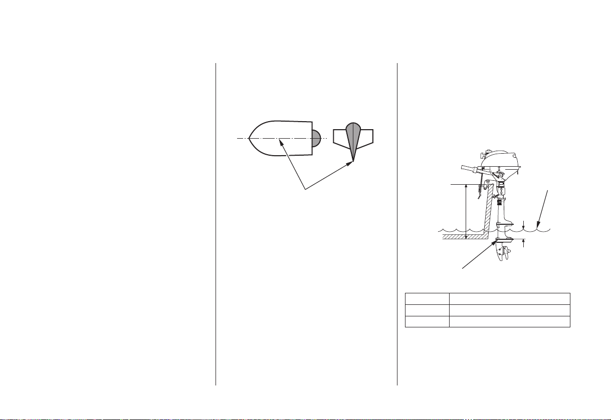
INSTALLATION POSITION
CENTER LINE
Install the outboard motor on the
center of the boat transom.
The antiventilation plate of the
outboard motor should be 0 2.0
−
inches below the bottom of the boat.
With the boat in the water and loaded,
the antiventilation plate should be
about 5.9 inches below the surface of
the water.
WATER
SURFACE
TTRRAANNSSOOMM HHEEIIGGHHTT
5.9 in (150 mm)
ANTIVENTILATION PLATE
Type:
S:
L:
Transom Height
16.5 in (418 mm)
22.5 in (571 mm)
17
Page 20
INSTALLATION
When the outboard motor is installed
extremely low, water may enter into
the engine under case and negatively
affect the performance and durability.
When installing, check that the
outboard motor is high enough from
the water level to keep the engine
under case from waves, splash, etc.
when the engine is stopped with the
boat fully loaded.
Propeller ventilation will occur if the
outboard motor is installed too high
on the boat transom.
Optimum installation height varies
with boat type and bottom shape.
Contact the boat manufacturer for
any special recommendations that are
unique to a specific model of boat.
If the transom needs to be modified
to accommodate the outboard motor,
contact the boat manufacturer and
follow their recommendations for
corrective action.
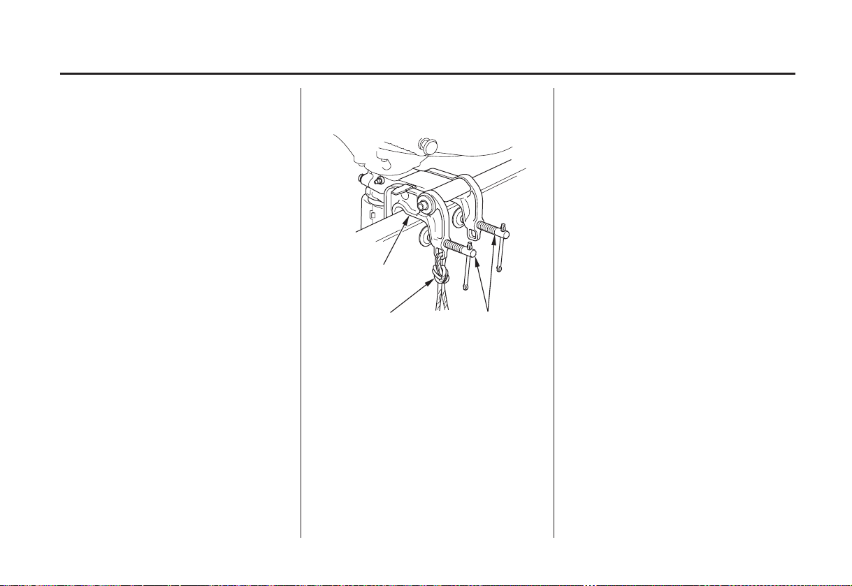
ATTACHMENT
STERN BRACKET
SAFETY ROPE
Attach the stern bracket to the boat
transom by tightening the clamp
screws.
Attach a rope from the boat to the
hole in the stern bracket. This will
help to prevent accidental loss of the
outboard motor.
CLAMP SCREWS
18
Page 21

TRANSOM ANGLE ADJUSTMENT
Use the transom angle adjusting bolt
(p. ) to adjust the angle of the
22
outboard motor so the propeller is
perpendicular to the surface of the
water.
INSTALLATION
19
Page 22
BEFORE OPERATION
ARE YOU READY TO GET UNDER WAY?
Your safety is your responsibility. A
little time spent in preparation will
significantly reduce your risk of
injury.
Knowledge
Read and understand this manual.
Know what the controls do and how
to operate them.
Familiarize yourself with the
outboard motor and its operation
before you get under way. Know
what to do in case of emergencies.
Familiarize yourself with all laws
and regulations relating to boating
and the use of outboard motors.
Safety
Always wear a PFD (Personal
Flotation Device) while on the boat.
Attach the emergency stop switch
lanyard securely to your PFD or to
your wrist.
IS YOUR OUTBOARD MOTOR READY TO GO?
For your safety, and to maximize the
service life of your equipment, it is
very important to take a few
moments before you operate the
outboard motor to check its condition.
Be sure to take care of any problem
you find, or have your authorized
Honda marine dealer correct it,
before you operate the outboard
motor.
Improperly maintaining
this outboard motor, or
failing to correct a problem
before operation, can cause
a malfunction in which you
could be seriously hurt or
killed.
Always perform a
preoperation inspection
before each operation, and
correct any problem.
20
Page 23
Safety Inspection Maintenance Inspection
BEFORE OPERATION
Look around the outboard motor
for signs of oil or gasoline leaks.
Wipe up any spills before starting
the engine.
Check the stern bracket to be sure
the outboard motor is securely
installed.
Check that all controls are
operating properly.
Replace any damaged parts.
Check that all fasteners are in
place and securely tightened.
Check the engine oil level (p. ).
Running the engine with a low oil
level can cause engine damage.
Check to be sure the propeller is
undamaged (p. ).
Check that the anode is securely
attached to the antiventilation plate
(p. ) and is not excessively
49
worn. The anode helps to protect
the outboard motor from corrosion.
Make sure the tool kit and
emergency starter rope are
onboard (p. ). Replace any
missing items.
Check the fuel level in the fuel
tank (p. ).
47
50
38
41
21
Page 24
OPERATION
SAFE OPERATING PRECAUTIONS
To safely realize the full potential of
this outboard motor, you need a
complete understanding of its
operation and a certain amount of
practice with its controls.
Before operating the outboard motor
for the first time, please review the
IMPORTANT SAFETY
INFORMATION
chapter titled
For your safety, avoid starting or
operating the engine in an enclosed
area. Your engine’s exhaust contains
poisonous carbon monoxide gas
which can collect rapidly in an
enclosed area and cause illness or
death.
on page and the
BEFORE OPERATION.
6
BREAK-IN PROCEDURE
Proper break-in procedure allows the
moving parts to wear in smoothly for
best performance and long service
life.
For the first 10 hours, run the
outboard motor at low speed, and
avoid full-throttle operation.
TRANSOM ANGLE ADJUSTMENT
The transom angle adjusting bolt is
used to adjust the angle of the
outboard motor in the normal
operating position (p. ).
To adjust, first tilt the outboard
motor so it is not resting on the bolt.
There are four adjustment positions.
Loosen the wing nut to free the
1.
adjusting bolt.
Adjust the angle of the motor, and
2.
tighten the wing nut. Be sure that
the bolt head and wing nut are
seated in one of the four
adjustment positions.
To prevent damage to the motor or
boat, make sure the transom angle
adjusting bolt is tight.
33
22
ADJUSTING BOLT AND WING NUT
Page 25
OPERATION
STARTING THE ENGINE
EMERGENCY STOP
SWITCH CLIP
LANYARD
Put the emergency stop switch clip
1.
in the engine stop switch, and
attach the lanyard to your PFD
(Personal Flotation Device) or to
your wrist, as shown.
ENGINE STOP
SWITCH
The engine will not start or run,
unless the clip is in the switch.
The emergency stop switch clip
and lanyard system is a safety
device that will stop the engine if
you fall away from the controls
while operating the boat.
Always attach the lanyard to your
PFD, or to your wrist, before
starting the engine.
OPEN
VENT KNOB
FUEL FILLER CAP
Open the fuel tank vent by turning
2.
the vent knob at least 2 or 3 turns
counterclockwise.
23
Page 26

OPERATION
FUEL VALVE LEVER
ON
Move the fuel valve lever to the
3.
ON position.
THROTTLE LEVER type: SA
THROTTLE LEVER
START
THROTTLE GRIP type: SHA, SCHA,
LCHA
THROTTLE GRIP
START
Move the throttle lever or the
4.
throttle grip to the START
position.
Do not start the engine with the
throttle lever or the throttle grip in
the FAST position, or the boat will
move suddenly when the engine
starts.
24
Page 27

CHOKE KNOB
OOPPEENN
CLOSED
To start a cold engine, pull the
choke knob to the CLOSED
position. To restart a warm engine,
leave the choke knob in the OPEN
position.
STARTER GRIP
Pull the recoil starter grip slowly
6.5.
until you feel resistance, then pull
briskly.
Return the starter grip gently.
OPERATION
If the choke knob was pulled to
7.
the CLOSED position to start the
engine, gradually push it to the
OPEN position as the engine
warms up.
Also, as the engine warms up, the
throttle lever or the throttle grip
can be turned to the SLOW
position without stalling.
Before getting under way, allow
8.
the engine to warm up sufficiently
to ensure good performance.
25
Page 28

OPERATION
EMERGENCY STARTING
If the recoil starter is not working
properly, you can start the engine
manually using the emergency starter
rope supplied with the tool kit.
RECOIL STARTER
STARTER ROPE
ENGINE
COVER
5 mm NUTS
Remove the three 5 mm nuts with
2.
an 8 mm wrench and remove the
recoil starter.
Remove the engine cover. Set the controls the same as for
3.1.
normal starting (see pages
). Use the choke control if
25
needed.
26
23
−
Set the knotted end of the
4.
emergency starter rope in the notch
in the flywheel. Wind the rope
clockwise around the flywheel, as
shown.
Page 29

OPERATION
Pull the emergency starter rope
5.
slowly until resistance is felt, then
pull briskly.
Keep away from moving parts
while pulling the rope.
If necessary, rewind the rope and
pull again. If the engine does not
start after several attempts, refer to
TAKING CARE OF
UNEXPECTED PROBLEMS,
56
.
p.
If the choke was used to start the
6.
engine, return the knob to the
normal operating position as the
engine warms up.
Leave the recoil starter assembly
7.
off, but install the engine cover (p.
).
13
Exposed moving parts can
cause injury.
Do not operate the
outboard motor without
the engine cover.
Use extreme care when
installing the engine
cover.
If it was necessary to remove the
8.
emergency stop switch lanyard
from your wrist to perform the
emergency starting procedure, be
sure the lanyard is attached to your
wrist before operating the
outboard motor.
Have your closest authorized
9.
Honda marine dealer check your
recoil starter system and correct
the problem, so you can use the
recoil starter.
The recoil starter assembly (p. )
should be reinstalled after the
recoil starter is working again.
Install the recoil starter assembly
with the engine stopped.
26
27
Page 30

OPERATION
STOPPING THE ENGINE
Emergency Engine Stopping
LANYARD
SWITCH CLIP
To stop the engine in an emergency,
pull the clip out of the engine stop
switch by pulling the lanyard.
We suggest that you stop the engine
this way occasionally to verify that
the engine or emergency stop switch
is operating properly.
Normal Engine Stopping
THROTTLE LEVER type: SA
THROTTLE LEVER
SLOW
THROTTLE GRIP type: SHA, SCHA,
LCHA
THROTTLE GRIP
SLOW
Move the throttle lever or the
1.
throttle grip to the SLOW position.
28
Page 31

OPERATION
ENGINE STOP SWITCH
PPUUSSHH
Push the engine stop switch button
until the engine stops.
In the event that the engine does
not stop when you push the engine
stop switch, pull the emergency
engine stop switch lanyard. If the
engine continues to run, move the
fuel valve lever to the OFF
position and pull the choke knob
to stop the engine.
FUEL VALVE LEVER FUEL CAP VENT KNOB
OOFFFF
Move the fuel valve lever to the
3.2. 4.
OFF position.
FUEL FILLER CAP
Close the fuel tank vent by turning
vent knob clockwise.
29
Page 32

OPERATION
THROTTLE OPERATION
THROTTLE LEVER type: SA
THROTTLE LEVER
FAST
THROTTLE GRIP type: SHA, SCHA,
LCHA
THROTTLE FRICTION KNOB
THROTTLE GRIP
FAST
Use the throttle friction knob to help
hold a constant throttle setting while
cruising.
Turn the knob clockwise to increase
throttle grip friction for holding a
constant speed.
Turn the knob counterclockwise to
decrease friction for easy grip
rotation.
30
Page 33

OPERATION
REVERSING THE OUTBOARD MOTOR
INPORTANT SAFETY PRECAUTIONS
Bef ore rotating the outboard
motor (f rom either f orward to
reverse or f rom reverse to
f orward) reduce the engine speed
to SLOW, or the boat could
capsize.
When operating in reverse,
proceed with caution to avoid
hitting any underwater
obstructions with the propeller.
THROTTLE LEVER type: SA
THROTTLE LEVER
SLOW
THROTTLE GRIP type: SHA, SCHA,
LCHA
THROTTLE GRIP FRICTION KNOB
THROTTLE GRIP
SLOW
For the throttle lever type: Move
1.
the throttle lever to the SLOW
position.
For the throttle grip type: Move
the throttle grip to the SLOW
position and hold it there by
turning the throttle grip friction
knob clockwise.
31
Page 34

OPERATION
To reverse direction, turn the
2.
outboard motor 180°, and then
pivot the tiller handle as shown.
For the throttle grip type, be
careful not to hold and move the
throttle grip when pivoting the
tiller handle.
STEERING
Steer by moving the tiller handle
opposite the direction you want the
boat to turn.
STEERING FRICTION BOLT
TTOO IINNCCRREEAASSEE
FFRRIICCTTIIOONN
TO DECREASE
FRICTION
Use the steering friction bolt to help
hold a steady course while cruising.
Turn the bolt clockwise to increase
steering friction for holding a steady
course.
Turn the bolt counterclockwise to
decrease friction for easy turning.
32
Page 35

OPERATION
CRUISING
Engine Speed
For best fuel economy, limit the
throttle opening to 80%. Use the
throttle friction control (p. ) to
help you hold a steady speed.
For rough water conditions or large
waves, slow down to prevent the
propeller from rising out of the water.
31
TRANSOM ANGLE
Install the outboard motor at the best
transom angle for stable cruising and
maximum power.
Transom angle too large: Incorrect
causes boat to ‘‘squat’’.
Transom angle too small: Incorrect
causes boat to ‘‘bow steer’’.
It is necessary to adjust the transom
angle to compensate for changes in
boat load, weight distribution, water
conditions, or propeller selection.
Under normal running conditions, the
boat will perform best when the
antiventilation plate is level with the
water.
When cruising into a high wind,
lower the transom angle slightly to
level the boat and improve stability.
With a tail wind, raise the transom
angle slightly.
Excessive transom angle during
operation can cause propeller
ventilation and overheating.
Transom Angle (Cruising)
O.K.
CORRECT
GIVES MAXIMUM PERFORMANCE
33
Page 36

OPERATION
MOORING, BEACHING, LAUNCHING
To raise the outboard motor out of
the water while the boat is moored, or
for maximum clearance when
beaching or launching, tilt the
outboard motor to the 75° position.
Stop the engine before tilting the
outboard motor. The 75° position is
not an operating position.
REAR CARRYING
HANDLE
STEERING
FRICTION BOLT
FRONT
CARRYING
HANDLE
75°
Stop the engine and turn the fuel
1.
valve lever off.
Close the fuel tank vent by turning
2.
the vent knob clockwise.
With the motor in the forward
3.
position, tilt the outboard motor
using the front and rear carrying
handles on the engine cover. The
spring-loaded tilt lever will
automatically move into position
and hold the outboard motor when
it reaches approximately 75°.
Adjust the steering friction bolt to
4.
keep the motor from moving.
34
Page 37

OPERATION
Do not use the tiller handle as a
lever to raise the outboard motor.
Applying excessive f orce to the
tiller handle can damage it.
If the motor is tilted in the reverse
position, crankcase oil will enter
the cylinder and may cause
dif f icult starting or may prevent
the engine from being cranked.
TILT LEVER
PPUULLLL
To return the outboard motor to
5.
the normal running position, hold
the outboard motor by the front
carrying handle on the engine case
and pull the tilt level toward you,
then lower the outboard motor
slowly.
NO
To avoid damaging the motor, be
very careful when mooring a boat,
especially when its motor is tilted up.
Don’t allow the motor to strike
against the pier or other boats.
35
Page 38

SERVICING YOUR OUTBOARD MOTOR
THE IMPORTANCE OF MAINTENANCE
Good maintenance is essential for
safe, economical, and trouble-free
operation. It will also help reduce air
pollution.
Improperly maintaining
this outboard motor, or
failure to correct a problem
before operation, can cause
a malfunction in which you
could be seriously hurt or
killed.
Always follow the
inspection and
maintenance
recommendations and
schedules in this owner’s
manual.
To help you properly care for your
outboard motor, the following pages
include a maintenance schedule,
routine inspection procedures, and
simple maintenance procedures using
basic hand tools. Other service tasks
that are more difficult, or require
special tools, are best handled by
professionals and are normally
performed by a Honda technician or
other qualified mechanic.
The maintenance schedule applies to
normal operating conditions. If you
operate your outboard motor under
unusual conditions, consult an
authorized Honda marine dealer for
recommendations applicable to your
individual needs and use.
Remember that your authorized
Honda marine dealer knows your
outboard motor best and is f ully
equipped to maintain and repair it.
To ensure the best quality and
reliability, use only new, genuine
Honda parts or their equivalents for
repair and replacement.
Maintenance, replacement, or
repair of the emission control
devices and systems may be
performed by any marine engine
repair establishment or individual,
using parts that are ‘‘certified’’ to
EPA standards.
36
Page 39

SERVICING YOUR OUTBOARD MOTOR
MAINTENANCE SAFETY Safety Precautions
Some of the most important safety
precautions follow. However, we
cannot warn you of every
conceivable hazard that can arise in
performing maintenance. Only you
can decide whether or not you should
perform a given task.
Failure to properly follow
maintenance instructions
and precautions can cause
you to be seriously hurt or
killed.
Always follow the
procedures and
precautions in the owner’s
manual.
Make sure the engine is off before
you begin any maintenance or
repairs. This will eliminate several
potential hazards:
−
Carbon monoxide poisoning
from engine exhaust.
Be sure there is adequate
ventilation whenever you
operate the engine.
−
Burns from hot parts.
system cool before touching.
−
Injury from moving parts.
Do not run the engine unless
instructed to do so.
Read the instructions before you
begin, and make sure you have the
tools and skills required.
To reduce the possibility of fire or
explosion, be careful when
working around gasoline. Use only
a nonflammable solvent, not
gasoline, to clean parts. Keep
cigarettes, sparks, and flames away
from all fuel-related parts.
Wear gloves when handling the
propeller to protect your hands
from sharp edges.Let the engine and exhaust
37
Page 40

SERVICING YOUR OUTBOARD MOTOR
TOOL KIT AND
EMERGENCY STARTER
ROPE
EMERGENCY STARTER ROPE
The following tools are supplied with
the outboard motor for simple
maintenance procedures and
emergency repairs. An emergency
starter rope is also supplied. Keep
these items on the boat, so they will
always be available if you need them.
If your tool kit needs replacement, it
is not available as a kit and each item
must be ordered individually.
38
8 10 mm WRENCH
×
COTTER PINS
FLAT/PHILLIPS
SCREWDRIVER
PLIERSSPARK PLUG WRENCH
SHEAR PINS
EMERGENCY STOP
SWITCH CLIP
TOOL BAG
Page 41

MAINTENANCE SCHEDULE
SERVICING YOUR OUTBOARD MOTOR
REGULAR SERVICE PERIOD
Perform at every indicated month or
operating hour interval, whichever
comes first.
ITEM
Engine oil
Gear case oil
Starter rope
Carburetor linkage
Valve clearance
Spark plug
Propeller and Cotter pin
Anode
Idle speed
Clutch shoes and drum
(With clutch type)
Lubricate more frequently when used in salt water.
(1)
These items should be serviced by an authorized Honda marine dealer, unless you have the proper tools and are mechanically proficient.
(2)
(3)
Check level
Change
Change
Check
Check-adjust
Check-adjust
Check-adjust
Replace
Check
Check
Check-adjust
Replace
Each use
○
○
○
First month
or
10 hrs.
○
○
(2)
○
(2)
○
Every 6 months
Every 200 hrs.
or
50 hrs.
○
○
○
(2)
○
○
(2)
○
Every year
Refer to the Honda shop manual for service procedures.
For professional/commercial use, log hours of operation to determine proper maintenance intervals.
(3)
or
150 hrs.
(2)
○
(2)
○
39
Page 42

SERVICING YOUR OUTBOARD MOTOR
REGULAR SERVICE PERIOD
Perform at every indicated month or
operating hour interval, whichever
comes first.
ITEM
Swivel case lining and
bush
Water sealing
Fuel line
Bolts and nuts
Lubrication
Fuel tank and tank filter
Crankcase breather tube
Lubricate more frequently when used in salt water.
(1)
These items should be serviced by an authorized Honda marine dealer, unless you have the proper tools and are mechanically proficient.
(2)
(3)
Replace
Replace
Check
Replace
Check-tightness
Grease
Clean
Check
Each use
○
First month
or
10 hrs.
Every 3 years (2)
Every 3 years (2)
Every 2 years (If necessary) (2)
(2)
○
(1)
○○
Every 6 months
or
50 hrs.
(1)
(2)
○
Every year
Refer to the Honda shop manual for service procedures.
For professional/commercial use, log hours of operation to determine proper maintenance intervals.
(3)
or
150 hrs.
(2)
○
(2)
○
40
Page 43

SERVICING YOUR OUTBOARD MOTOR
ENGINE COVER REMOVAL
AND INSTALLATION
ENGINE COVER
STRAP
The engine cover retaining strap
fastens the engine cover to the
outboard motor.
To remove the engine cover, unhook
the engine cover retaining strap, then
lift the engine cover off the outboard
motor.
To install the engine cover, place the
cover on the outboard motor, then
hook the engine cover retaining strap
securely.
Engine Oil Level Check Engine Oil Change
Check the engine oil level with the
engine stopped and the outboard
motor in the vertical position.
UUPPPPEERR LLIIMMIITT
LLOOWWEERR LLIIMMIITT
OIL LEVEL
INSPECTION
WINDOW
Check the oil level shown on the
1.
oil level inspection window.
If the oil level is near or below the
2.
lower limit mark on the window,
fill with the recommended oil to
the upper limit mark on the
window.
Running the engine with a low oil
level can cause engine damage.
An engine oil evacuation device may
be used to remove the engine oil.
Drain the used oil while the engine is
warm. Warm oil drains quickly and
completely.
41
Page 44

SERVICING YOUR OUTBOARD MOTOR
Move the fuel valve lever to the
1.
OFF position, and turn the fuel cap
vent knob clockwise to close the
fuel vent.
Loosen the oil drain bolt, and turn
2.
the motor on its tiller handle side.
Remove the oil drain bolt and
3.
washer to drain the oil.
UUPPPPEERR LLIIMMIITT MMAARRKK
LLOOWWEERR LLIIMMIITT MMAARRKK
OIL LEVEL INSPECTION
WINDOW
OIL DRAIN BOLT
OIL FILLER CAP
OIL FILLER HOLE
Stand the outboard motor in a
4.
vertical position, and install a new
washer and the oil drain bolt
securely.
Remove the engine cover.
5.
Improper disposal of engine oil
can be harmful to the environment.
If you change your own oil, please
dispose of the used oil properly.
Put it in a sealed container, and
take it to a recycling center. Do
not discard it in a trash bin, dump
it on the ground or pour it down a
drain.
Remove the oil filler cap and fill
6.
the crankcase with the
recommended oil (see page ) up
43
to the upper limit mark on the oil
level inspection window.
Engine oil refill capacity:
0.26 US qt (0.25 )
Install the oil filler cap and tighten
7.
it securely.
Install the engine cover.
8.
42
Page 45

SERVICING YOUR OUTBOARD MOTOR
Engine Oil Recommendations
Oil is a major factor affecting
performance and service life. Use
4-stroke automotive detergent oil.
SAE Viscosity Grade
AMBIENT TEMPERATURE
SAE 10W-30 is recommended for
general use.
The SAE oil viscosity and service
classification are in the API label on
the oil container. Honda recommends
that you use API SERVICE category
SG, SH or SJ oil with the ‘‘starburst’’
certification mark displayed on the
container.
43
Page 46

SERVICING YOUR OUTBOARD MOTOR
Lubrication Points
Apply marine waterproof grease to the following parts:
Lubrication interval:
10 operating hours or a month after the date of purchase
for initial, then every 50 operating hours or 6 months.
To prevent corrosion, apply anticorrosion oil to pivot
surf aces where grease cannot penetrate.
TILT LEVER
CLAMP SCREW
THROTTLE ARM
THROTTLE ARM
CHOKE ARM
STEERING HANDLE
SWIVEL CASE
STEERING FRICTION BOLT
TRANSOM ANGLE
ADJUSTING BOLT
THRUST RECEIVER
Apply Honda Marine Corrosion Inhibitor (or equivalent) to all areas under the engine cover and any exposed metal
surfaces.
44
Page 47

SERVICING YOUR OUTBOARD MOTOR
Spark Plug Service
RECOMMENDED SPARK PLUG:
CR4HSB (NGK)
U14FSR-UB (DENSO)
Incorrect spark plug can cause
engine damage.
Remove the engine cover (p. ).
1.
Disconnect the spark plug cap
2.
from the spark plug.
Remove the spark plug with a
3.
spark plug wrench and screwdriver
supplied in the tool kit.
41
SPARK PLUG WRENCH
SEALING WASHER
Inspect the spark plug. Replace it
4. 5.
if the electrode is worn, or if the
insulator is cracked or chipped.
0.024 0.028 in
−
(0.60 0.70 mm)
−
Measure the spark plug electrode
gap with a suitable gauge. The gap
should be 0.024 0.028 inches
−
(0.60 0.70 mm). Correct the
−
gap, if necessary, by carefully
bending the side electrode.
45
Page 48

SERVICING YOUR OUTBOARD MOTOR
Install the spark plug carefully, by
6.
hand, to avoid cross-threading.
After the spark plug seats, tighten
7.
with a spark plug wrench supplied
in the tool kit to compress the
sealing washer.
If reinstalling the used spark plug,
tighten 1/8 - 1/4 turn after the
spark plug seats.
If reinstalling a new spark plug,
tighten 1/2 turn after the spark
plugs seat.
A loose spark plug can overheat
and damage the engine.
Overtightening the spark plug can
damage the threads in the cylinder
head.
Attach the spark plug cap.
8.
Install the engine cover.
9.
46
Page 49

SERVICING YOUR OUTBOARD MOTOR
REFUELING
FUEL TANK CAPACITY:
0.26 US gal (1.0
With the engine stopped, turn the
vent knob counterclockwise to open
the fuel tank vent and remove the
fuel filler cap.
Refill the fuel tank if the fuel level is
low.
)
FUEL FILLER CAP
VENT KNOB
MAXIMUM FUEL LEVEL
FUEL TANK
FUEL
Refuel in a well-ventilated area. Fill
the tank to the maximum fuel level.
After ref ueling, install the cap and
tighten it securely. Turn the vent
knob clockwise to close the fuel tank
vent.
Gasoline is highly
flammable and explosive.
You can be burned or
seriously injured when
handling fuel.
Stop the engine and keep
heat, sparks, and flame
away.
Handle fuel only
outdoors.
Wipe up spills
immediately.
Never refill the fuel tank inside a
building where gasoline fumes may
reach flames or sparks. Keep
gasoline away from appliance pilot
lights, barbecues, electric appliances,
power tools, etc.
Spilled fuel is not only a fire hazard,
it causes environmental damage.
Wipe up spills immediately.
47
Page 50

SERVICING YOUR OUTBOARD MOTOR
FUEL RECOMMENDATIONS
Use unleaded gasoline with a pump
octane rating of 86 or higher.
This outboard motor is certified to
operate on unleaded gasoline.
Unleaded gasoline produces fewer
engine and spark plug deposits and
extends exhaust system life.
Never use stale or contaminated
gasoline or an oil/gasoline mixture.
Avoid getting dirt or water in the fuel
tank.
Occasionally you may hear a light
‘‘spark knock’’ or ‘‘pinging’’
(metallic rapping noise) while
operating under heavy loads. This is
no cause for concern.
If spark knock or pinging occurs at a
steady engine speed, under normal
load, change brands of gasoline. If
spark knock or pinging persists, see
an authorized Honda marine dealer.
Running the engine with persistent
spark knock or pinging can cause
engine damage.
Running the engine with persistent
spark knock or pinging is misuse,
and the
Warranty
damaged by misuse.
Distributor’s Limited
does not cover parts
48
Page 51

SERVICING YOUR OUTBOARD MOTOR
Recoil Starter Rope Inspection Anode Replacement
RECOIL STARTER ROPE
Inspect the recoil starter rope, and
replace it if it becomes frayed.
Always keep the emergency starter
rope on the boat in case the recoil
starter rope fails.
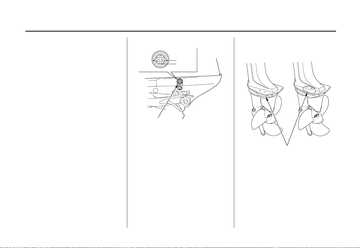
Short shaft type
Long shaft type
ANODE
The anode is made of a sacrificial
material that helps to protect the
outboard motor from corrosion.
Replace the anode when it has been
reduced to about half its original size,
or if it is crumbling.
Painting or coating the anode will
def eat its purpose and will lead to
rust and corrosion damage to the
outboard motor. The anode must be
exposed to the water in order to
protect the outboard motor.
49
Page 52

SERVICING YOUR OUTBOARD MOTOR
Propeller Replacement
Before replacing the propeller,
remove the clip from the engine stop
switch to prevent any possibility of
the engine being started while you
are working with the propeller.
The propeller blades may have sharp
edges, so wear heavy gloves to
protect your hands.
Operating the outboard motor at
higher altitudes will reduce available
power. This may require decreasing
the propeller pitch to maintain correct
engine RPM.
Removal Installation
COTTER PIN
SHEAR PIN
PROPELLER
Remove the cotter pin, then remove
the propeller and shear pin.
Install the propeller in the reverse
order of removal.
Use a genuine Honda stainless steel
cotter pin and bend the pin ends as
shown. A non-stainless steel cotter
pin can deteriorate if used in
saltwater.
Spare shear pins and cotter pins are
provided on the engine undercase (p.
COTTER PIN
).38
50
Page 53

STORAGE
STORAGE PREPARATION Fuel
Proper storage preparation is
essential for keeping your outboard
motor troublefree and looking good.
The following steps will help to keep
rust and corrosion from impairing
your outboard motor’s function and
appearance, and will make the engine
easier to start when you use the
outboard motor again.
Cleaning
Thoroughly clean and flush the
outboard motor with f resh water after
operation in dirty water or salt water.
Wash the outside of the outboard
motor with clean, fresh water to
remove mud, salt, seaweed, etc.
Touch up any damaged paint, and
coat areas that may rust with Honda
Corrosion Inhibitor, or equivalent.
Lubricate controls with a silicone
spay lubricant.
Gasoline will oxidize and deteriorate
in storage. Old gasoline will cause
hard starting, and it leaves gum
deposits that clog the fuel system. If
the gasoline in your fuel tank and
carburetor deteriorates during storage,
you may need to have the carburetor
and other fuel system components
serviced or replaced.
The length of time that gasoline can
be left in your fuel tank and
carburetor without causing functional
problems will vary with such factors
as gasoline blend, your storage
temperatures, and whether the fuel
tank is partially or completely filled.
The air in a partially filled fuel tank
promotes fuel deterioration. Very
warm storage temperatures accelerate
fuel deterioration. Fuel deterioration
problems may occur within a few
months, or even less if the gasoline
was not fresh when you filled the
fuel tank.
Distributor’s Limited Warranty
The
does not cover fuel system damage
or engine performance problems
resulting from neglected storage
preparation.
You can extend fuel storage life by
adding a gasoline stabilizer that is
formulated for that purpose, or you
can avoid fuel deterioration problems
by draining all the fuel from the fuel
tank and carburetor.
51
Page 54

STORAGE
Adding a Fuel Stabilizer Draining the Fuel Tank and
Carburetor
When adding a fuel stabilizer, fill the
fuel tank with fresh gasoline. If only
partially filled, air in the tank will
promote fuel deterioration during
storage. If you keep a container of
gasoline for refueling, be sure that it
contains only fresh gasoline.
Add fuel stabilizer following the
1.
manufacturer’s instructions.
Refer to previous page for proper
2.
running procedure. After adding a
fuel stabilizer, run the engine
outdoors for 10 minutes to be sure
that the treated gasoline has
replaced the untreated gasoline in
the carburetor.
Starting the engine on land:
For safety, remove the propeller from
the outboard motor (p. ).
50
ANTIVENTILATION PLATE
Place a container under the
outboard motor, and fill it with
clean, fresh water. The water level
must be at least 6 inches above the
antiventilation plate.
Running the engine without water
can cause overheating and
damage.
Damage caused by running the
outboard motor without water is not
covered by the
Warranty.
Turn the engine OFF, turn the fuel
3.
valve lever OFF (p.13), and close
the fuel cap vent knob (p.15).
Distributor’s Limited
You can avoid fuel deterioration
problems by draining the fuel tank
and carburetors.
With the outboard motor in a
1.
vertical position, place an
approved gasoline container below
the fuel drain outlet, and use a
funnel to avoid spilling fuel.
Gasoline is highly
flammable and explosive.
You can be burned or
seriously injured when
handling fuel.
Stop the engine and keep
heat, sparks, and flame
away.
Handle fuel only
outdoors.
Wipe up spills
immediately.
52
Page 55

STORAGE
With the engine stopped, turn the
2.
fuel cap vent knob
counterclockwise to open the fuel
vent and remove the fuel filler cap.
Loosen the carburetor drain screw
3.
and move the fuel valve lever to
the ON position to drain the
carburetor and the fuel tank into an
approved gasoline container.
DRAIN SCREW
After draining is completed,
4.
tighten the carburetor drain screw
and turn the fuel valve to the OFF
position.
Engine Oil
Change the engine oil (p.
1.
).
42
Remove the spark plug (p. ),
2.
and remove the clip from the
engine stop switch.
Pour a tablespoon (5 10 cm ) of
3.
−
clean engine oil into the cylinder.
Pull the starter rope several times
4.
to distribute the oil in the cylinder.
Reinstall the spark plug (p. ).
5. 46
41
−
45
3
STORAGE PRECAUTIONS
Select a well-ventilated storage area.
If possible, avoid storage areas with
high humidity.
To carry the outboard motor, hold it
by the carrying handle, as shown.
Lif ting the outboard motor by the
engine cover, or using the installed
outboard motor as a handle or lever
to move the boat, can damage the
outboard motor.
If your fuel tank contains gasoline,
store it away from any appliance that
operates with a flame, such as a
furnace, water heater, or clothes
dryer. Also avoid any area with a
spark-producing electric motor, or
where power tools are operated.
Store the outboard motor either
vertically or horizontally with the
tiller handle side up.
Turn the fuel filler cap vent knob
5.
clockwise to close the fuel vent.
53
Page 56

STORAGE
CORRECT
CASE PROTECTOR
If storing horizontally, be sure to fold
the tiller handle, and rest the
outboard motor on its case protectors.
Any other horizontal storage position
may cause damage or oil leakage.
INCORRECT
Cover the outboard motor to keep out
dust. Do not use sheet plastic as a
dust cover. A nonporous cover will
trap moisture, promoting rust and
corrosion.
REMOVAL FROM STORAGE
Check your outboard motor as
described in the
OPERATION
If the cylinder was coated with oil
during storage preparation, the
engine may smoke briefly at startup.
This is normal.
BEFORE
chapter of this manual.
54
Page 57

TRANSPORTING
WITH OUTBOARD MOTOR INSTALLED ON BOAT
When trailering a boat with the
outboard motor attached, leave the
engine in the normal running position,
if possible, and tighten the steering
friction bolt securely (p. ).
If there is insufficient road clearance
in the normal running position, then
tilt the outboard motor and use a
motor support bar, or remove the
outboard motor from the boat. Refer
to the manufacturer’s instructions for
using a motor support bar.
MOTOR SUPPORT BAR
(commercially available)
WITH OUTBOARD MOTOR REMOVED FROM BOAT
Remove the outboard motor from the
boat and secure the outboard motor
in either the vertical or horizontal
position shown on p. .3254
To carry, hold the outboard motor by
the carrying handle, as shown.
Lif ting the outboard motor by the
engine cover, or using the
installed outboard motor as a
handle or lever to move the boat,
can damage the outboard motor.
55
Page 58

TAKING CARE OF UNEXPECTED PROBLEMS
ENGINE WILL NOT START Possible Cause Correction
Check emergency stop switch
1.
clip.
Check control positions.
2.
Clip not inserted in stop switch.
Choke OPEN.
Throttle lever or grip not in
START position.
Insert clip in stop switch.
Pull choke knob to CLOSED
position, unless engine is warm (p.
).
11
Turn throttle lever or grip to
START position (p. ).
24
56
Page 59

TAKING CARE OF UNEXPECTED PROBLEMS
(continued)
Check fuel. Out of fuel. Refuel (p. ).
3.
CorrectionPossible CauseENGINE WILL NOT START
47
Remove and inspect spark plug.
4.
Take outboard motor to an
5.
authorized Honda marine dealer,
or refer to the shop manual.
Open fuel tank vent (p. ).Fuel vent closed.
Fuel valve lever in the OFF
position. 13
Bad fuel; boat stored without
treating or draining gasoline, or
refueled with bad gasoline.
Spark plug faulty, fouled or
improperly gapped.
Spark plug wet with fuel (flooded
engine).
Carburetor malfunction, ignition
malfunction, stuck valves, etc.
Move the fuel valve lever to the
ON position (p. ).
Drain fuel tank and carburetors
(p. ). Refill with fresh gasoline
52
(p. ).
47
Gap or replace spark plug (p. ).
Dry and reinstall spark plug. Start
engine with choke and throttle open.
Replace or repair faulty
components as necessary.
15
45
57
Page 60

TAKING CARE OF UNEXPECTED PROBLEMS
AFTER STARTING
CorrectionPossible CauseHARD STARTING OR STALLS
Check control positions. Pull choke knob to CLOSED
1.
Check fuel. Fuel vent closed. Open fuel tank vent (p. ).
2.
Remove and inspect spark plug. Spark plug faulty, fouled or
3.
Take outboard motor to an
4.
authorized Honda marine dealer,
or refer to the shop manual.
Choke OPEN.
Throttle lever or grip not in
START position.
Bad fuel; boat stored without
treating or draining gasoline, or
refueled with bad fuel.
improperly gapped.
Carburetor malfunction, ignition
malfunction, etc.
position, unless engine is warm (p.
).
11
Turn throttle lever or grip to
START (p. ).
Drain fuel tank and carburetor (p.
). Refill with fresh gasoline (p.
52
).
47
Gap or replace spark plug (p. ).
Replace or repair faulty
components as necessary.
24
58
15
45
Page 61

TAKING CARE OF UNEXPECTED PROBLEMS
ENGINE WILL NOT DRIVE
THE PROPELLER
Check shear pin.
1. 50
Take outboard motor to an
2.
authorized Honda marine dealer,
or refer to the shop manual.
Broken shear pin.
Damaged clutch, drive train, or
engagement mechanism.
Possible Cause Correction
Replace shear pin (p. ).
Replace or repair faulty
components as necessary.
59
Page 62

TAKING CARE OF UNEXPECTED PROBLEMS
SUBMERGED MOTOR
A submerged outboard motor must
be serviced immediately after it is
recovered from the water in order to
minimize corrosion.
If there is a Honda marine dealer
nearby, take the motor to the dealer
immediately. If you are far from a
dealer, proceed as follows:
Remove the engine cover, and
1.
rinse the outboard motor with
fresh water to remove salt water,
sand, mud, etc.
Drain the carburetor as described
2.
on p. .
52
Change the engine oil as described
3.
on p. . If there was water
in the engine crankcase, or if the
used engine oil showed signs of
water contamination, then a second
engine oil change should be
performed after running the engine
for half an hour.
−
4241
STARTER GRIP
Remove the spark plug (p. ),
4.
and remove the clip from the
engine switch. Pull the recoil
starter grip, rotate the flywheel a
few revolutions to completely
expel any water from the cylinder.
If the engine was running when it
submerged, there may be
mechanical damage, such as a bent
connecting rod. If the engine binds
when cranked, do not attempt to
run the engine until it has been
repaired.
45
60
Page 63

TAKING CARE OF UNEXPECTED PROBLEMS
When cranking the engine with
an open ignition circuit (spark
plug removed from the ignition
circuit), remove the clip from
the engine stop switch to
prevent possible damage to the
ignition system.
Pour a teaspoon of engine oil into
5.
the spark plug hole, then pull the
recoil starter grip several times to
lubricate the inside of the cylinder.
Reinstall the spark plug, and put
6.
the emergency stop switch clip
into the switch.
Attempt to start the engine.
7.
If the engine fails to start, remove
the spark plug, and dry it, then
reinstall the spark plug and attempt
to start the engine again.
If the engine starts, and no
mechanical damage is evident,
continue to run the engine for a
half hour or longer.
As soon as possible, take the
8.
outboard motor to an authorized
Honda marine dealer for
inspection and service.
61
Page 64

TECHNICAL AND CONSUMER INFORMATION
TECHNICAL INFORMATION
Serial Number Locations
Record the product identification
number and engine serial number in
the space provided on this page. You
will need these numbers when
ordering parts, and when making
technical or warranty inquiries
(p. ).
70
PRODUCT
IDENTIFICATION
NUMBER
The product identification number is
stamped on a plate attached on side
of the stern bracket.
Product identification number:
ENGINE SERIAL
NUMBER
The engine serial number is
stamped on the engine.
Engine serial number:
62
Page 65

TECHNICAL AND CONSUMER INFORMATION
Carburetor Modification for High Altitude Operation
At high altitude, the standard
carburetor air-fuel mixture will be
too rich. Performance will decrease,
and fuel consumption will increase.
A very rich mixture will also foul the
spark plug and cause hard starting.
High altitude performance can be
improved by specific modifications
to the carburetor. If you always
operate your outboard motor at
altitudes above 5,000 feet (1,500
meters), have an authorized Honda
marine dealer perform this carburetor
modification.
Even with carburetor modification,
engine horsepower will decrease
about 3.5% for each 1,000-foot (300meter) increase in altitude. The effect
of altitude on horsepower will be
greater than this if no carburetor
modification is made.
When the carburetor has been
modif ied f or high altitude operation,
the air-f uel mixture will be too lean
f or low altitude use. Operation at
altitudes below 5,000 feet (1,500
meters) with modified carburetor
may cause the engine to overheat
and result in serious engine damage.
For use at low altitudes, have an
authorized Honda marine dealer
return the carburetor to original
f actory specif ications.
63
Page 66

TECHNICAL AND CONSUMER INFORMATION
Oxygenated Fuels
Some conventional gasolines are
being blended with alcohol or an
ether compound. These gasolines are
collectively referred to as oxygenated
fuels. To meet clean air standards,
some areas of the United States and
Canada use oxygenated fuels to help
reduce emissions.
If you use an oxygenated fuel, be
sure it is unleaded and meets the
minimum octane rating requirement.
Before using an oxygenated fuel, try
to confirm the fuel’s contents. Some
states/provinces require this
information to be posted on the pump.
The following are the EPA-approved
percentages of oxygenates:
ETHANOL:
10% by volume.
You may use gasoline containing up
to 10% ethanol by volume. Gasoline
containing ethanol may be marketed
under the name ‘‘Gasohol’’.
MTBE:
15% by volume.
You may use gasoline containing up
to 15% MTBE by volume.
METHANOL:
alcohol; 5% by volume.
You may use gasoline containing up
to 5% methanol by volume, as long
as it also contains cosolvents and
corrosion inhibitors to protect the
fuel system. Gasoline containing
more than 5% methanol by volume
may cause starting and/or
performance problems. It may also
ethyl or grain alcohol;
Methyl Tertiary Butyl Ether;
methyl or wood
damage metal, rubber, and plastic
parts of your fuel system.
If you notice any undesirable
operating symptoms, try another
service station, or switch to another
brand of gasoline.
Fuel system damage or performance
problems resulting from the use of an
oxygenated fuel containing more
than the percentages of oxygenates
mentioned above are not covered
under warranty.
64
Page 67

TECHNICAL AND CONSUMER INFORMATION
Emission Control System Information
Source of Emissions
The combustion process produces
carbon monoxide, oxides of nitrogen,
and hydrocarbons. Control of
hydrocarbons and oxides of nitrogen
is very important because, under
certain conditions, they react to form
photochemical smog when subjected
to sunlight. Carbon monoxide does
not react in the same way, but it is
toxic.
Honda utilizes lean carburetor
settings and other systems to reduce
the emissions of carbon monoxide,
oxides of nitrogen, and hydrocarbons.
Air Acts
EPA and California regulations
require all manufacturers to furnish
written instructions describing the
operation and maintenance of
emission control systems.
The following instructions and
procedures must be followed in order
to keep the emissions from your
Honda engine within the emission
standards.
Tampering and AlteringThe U.S. and Calif ornia Clean
Tampering with or altering the
emission control system may increase
emissions beyond the legal limit.
Among those acts that constitute
tampering are:
Removal or alteration of any part
of the intake, fuel, or exhaust
systems.
Alterations that would cause the
engine to operate outside its design
parameters.
65
Page 68

TECHNICAL AND CONSUMER INFORMATION
Emissions
If you are aware of any of the
following symptoms, have your
engine inspected and repaired by
your servicing dealer.
Hard starting or stalling after
starting.
Rough idle.
Misfiring or backfiring under load.
Afterburning (backfiring).
Black exhaust smoke or high fuel
consumption.
Replacement PartsProblems That May Aff ect
The emission control systems on
your Honda engine were designed,
built, and certified to conform with
EPA and California emission
regulations. We recommend the use
of genuine Honda parts whenever
you have maintenance done. These
original-design replacement parts are
manufactured to the same standards
as the original parts, so you can be
confident of their performance. The
use of replacement parts that are not
of the original design and quality
may impair the effectiveness of your
emission control system.
A manufacturer of an aftermarket
part assumes the responsibility that
the part will not adversely affect
emission performance. The
manufacturer or rebuilder of the part
must certify that use of the part will
not result in a failure of the engine to
comply with emission regulations.
Maintenance
Follow the maintenance schedule on
p. . Remember that this schedule
39
is based on the assumption that your
machine will be used for its designed
purpose. Sustained high-load
operation, or use in unusual
conditions, will require more
frequent service.
66
Page 69

TECHNICAL AND CONSUMER INFORMATION
Star Label
A Star label was applied to this
outboard motor in accordance with
the requirements of the California
Air Resources Board.
The Star Label means Cleaner Marine Engine
This engine has been certified as a:
The Symbol for Cleaner Marine Engines:
Cleaner Air and Water -
Better Fuel Economy -
conventional carbureted two-stroke engines, saving money and resources.
Longer Emission Warranty -
for healthier lifestyle and environment.
burns up to 30 - 40 percent less gas and oil than
protects consumer for worry free operation.
67
Page 70

TECHNICAL AND CONSUMER INFORMATION
The one-star label identifies engines that meet the Air Resources Board’s
One Star
Low
Emission
Two Stars
Very Low
Emission
Three Stars
Ultra Low
Emission
Four Stars
Super Ultra
Low Emission
Personal Watercraft and Outboard marine engine 2001 exhaust emission
standards. Engines meeting these standards have 75% lower emissions than
conventional carbureted two-stroke engines. These engines are equivalent
to the U.S.EPA’s 2006 standards for marine engines.
The two-star label identifies engines that meet the Air Resources Board’s
Personal Watercraft and Outboard marine engine 2004 exhaust emission
standards. Engines meeting these standards have 20% lower emissions than
One Star-Low Emission engines.
The three-star label identifies engines that meet the Air Resources Board’s
Personal Watercraft and Outboard marine engine 2008 exhaust emission
standards or the Sterndrive and inboard marine engine 2003-2008 exhaust
emission standards. Engines meeting these standards have 65% lower
emissions than One Star-Low Emission engines.
The four-star label identifies engines that meet the Air Resources Board’s
Sterndrive and Inboard marine engine 2009 exhaust emission standards.
Personal Watercraft and Outboard marine engines may also comply with
these standards. Engines meeting these standards have 90% lower
emissions than One Star-Low Emission engines.
68
Cleaner Watercraft - Get the Facts
1-800-END-SMOG
www.arb.ca.gov
Page 71

Specifications
TECHNICAL AND CONSUMER INFORMATION
MODEL
Description Code
Type
Overall length
Overall width
Overall height
Transom height
Weight
Rated power
Full throttle range
Engine type
Displacement
Sparkpluggap
Starter system
Ignition system
Lubrication system
Specified oil
Oil capacity
BZBK
SA SHA SCHA LCHA
26.7 lbs
(12.1 kg)
4strokeOHV1cylinder
0.024 0.028 in (0.60 0.70 mm)
Transistorized Ignition Control Module (ICM)
Engine:
Gear case:
Engine:
0.26 US qt (0.25
Gear case:
0.05 US qt (0.05
BF2D
16.1 in (410 mm)
11.0 in (280 mm)
37.2 in
(945 mm)
16.5 in
(418 mm)
27.3 lbs
(12.4 kg)
1.5 kW (2.0 HP)
−
5,000 6,000 rpm
3.5cu-in(57cm
−−
Recoil starter
Oil slinger system
API standard (SG, SH or SJ)
SAE 10W-30
API standard (GL4/5)
SAE 90 outboard motor
gear oil
28.0 lbs
(12.7 kg)
)
)
BZBF
43.3 in
(1,100
mm)
22.5 in
(571 mm)
29.3 lbs
(13.3 kg)
)
CARB star label
Cooling system
Exhaust system
Spark plug
Fuel
Tank capacity
Steering equipment
Steering angle
Transom angle
Tilt angle
Clutch system
Tuneup
Sparkpluggap
Idle speed
Valve clearance
(cold)
Other specifications
ULTRA LOW EMISSION
Engine: Forced air cooling
Underwater exhaust
CR4HSB (NGK)
U14FSR-UB (DENSO)
Automotive unleaded gasoline
(86 pump octane or higher)
0.26 US gal (1.0
Tiller handle
4 stages (5°, 10°, 15°, 20°)
0.024 0.028 in
(0.60 0.70 mm)
−
2,000 100 rpm
Intake:
Exhaust:
0.08 0.02 mm
0.11 0.02 mm
No other adjustment is needed
360°
75°
Centrifugal clutch
−
±
±
±
)
Seepage45
See shop
See shop
Honda outboards are power rated in accordance with NMMA procedures and using the ICOMIA standard 28/23.
manual
manual
69
Page 72

TECHNICAL AND CONSUMER INFORMATION
CONSUMER INFORMATION
Honda Publications
These publications will give you
additional information for
maintaining and repairing your
outboard motor. You may order them
from your Honda marine dealer.
Shop Manual
This manual covers complete
maintenance and overhaul procedures.
It is intended to be used by a skilled
technician.
Parts Catalog
This manual provides complete,
illustrated parts lists.
Customer Service Information
Honda Marine dealership personnel
are trained professionals. They
should be able to answer any
question you may have. If you
encounter a problem that your dealer
does not solve to your satisfaction,
please discuss it with the dealership’s
management. The Service Manager
or General Manager can help. Almost
all problems are solved in this way.
If you are dissatisfied with the
decision made by the dealership’s
management, contact the Honda
Marine Customer Relations Office.
You can write:
American Honda Motor Co., Inc.
Marine Division
Customer Relations Office
4900 Marconi Drive
Alpharetta, Georgia 30005-8847
Or telephone: (770) 497-6400
When you write or call, please give
us this information:
Model and serial numbers (p. )62
Name of the dealer who sold the
outboard motor to you
Name and address of the dealer
who services your outboard motor
Date of purchase
Your name, address, and telephone
number
A detailed description of the
problem
70
Page 73

Page 74

Page 75

Page 76

Page 77

WIRING DIAGRAM
75
Page 78

INDEX
............................................................................Anode . 16
..............................................................Replacement . 49
?
.........ARE YOU READY TO GET UNDER WAY . 20
...........................................................ATTACHMENT . 18
................................................BEFORE OPERATION . 20
...........................................BREAK-IN PROCEDURE . 22
Carburetor Modification for High Altitude
...................................................................Operation . 63
......................Centrifugal Clutch (SCHA/LCHA type) . 16
...................................................................Choke Knob . 11
................................................................Clamp Screws . 15
........COMPONENT AND CONTROL LOCATIONS . 10
...................................CONSUMER INFORMATION . 70
..................................................................CONTROLS . 11
....................................CONTROLS AND FEATURES . 9
CONTROLS AND FEATURE IDENTIFICATION
........................................................................CODES . 9
....................................................................CRUISING . 33
......................................Customer Service Information . 70
−
........................Distributors Limited Warranty 2005 . 71
.........................................EMERGENCY STARTING . 26
.........................Emission Control System Information . 65
..............................Emission Control System Warranty . 73
Engine
Cover
...................REMOVAL AND INSTALLATION . 41
......................................................Retaining Strap . 13
Oil
...................................................................Change . 41
..........................................................Level Check . 41
.....................................Level Inspection Window . 16
.................................................Recommendations . 43
............................Engine Stop Switch and Switch Clip . 11
......ENGINE WILL NOT DRIVE THE PROPELLER . 59
......................................ENGINE WILL NOT START . 56
Fuel
..........................................................Cap Vent Knob . 15
..........................................RECOMMENDATIONS . 48
...............................................................Valve Lever . 13
HARD STARTING OR STALLS AFTER
...............................................................STARTING . 58
76
Page 79

INDEX
...........................................................................INDEX . 76
..........................................................INSTALLATION . 17
......................................INSTALLATION POSITION . 17
IS YOUR OUTBOARD MOTOR
?
....................................................READY TO GO . 20
.........................................................Lubrication Points . 44
.........................................MAINTENANCE SAFETY . 37
................................................................OPERATION . 22
....................................................OTHER FEATURES . 16
..........................................................Oxygenated Fuels . 64
.........................................POWER REQUIREMENTS . 17
..................................................Propeller Replacement . 50
.........................................................Recoil Starter Grip . 13
......................................Recoil Starter Rope Inspection . 49
.................................................................REFUELING . 47
....................IMPORTANT SAFETY INFORMATION . 6
...................................MAINTENANCE SCHEDULE . 39
...................MOORING, BEACHING, LAUNCHING . 34
...................................OUTBOARD MOTOR SAFETY . 6
...................................REMOVAL FROM STORAGE . 54
................REVERSING THE OUTBOARD MOTOR . 31
........................SAFE OPERATING PRECAUTIONS . 22
....................................SAFETY LABEL LOCATIONS . 8
...............................................Serial Number Locations . 62
..............SERVICING YOUR OUTBOARD MOTOR . 36
........................................................Spark Plug Service . 45
................................................................Specifications . 69
......................................................................Star Label . 67
..........................................STARTING THE ENGINE . 23
....................................................................STEERING . 32
....................................................Steering Friction Bolt . 15
STOPPING THE ENGINE
.....................................Emergency Engine Stopping . 28
...........................................Normal Engine Stopping . 28
....................................................................STORAGE . 51
........................................STORAGE PRECAUTIONS . 53
........................................STORAGE PREPARATION . 51
............................................Adding a Fuel Stabilizer . 52
....................................................................Cleaning . 51
....................Draining the Fuel Tank and Carburetor . 52
..................................................................Engine oil . 53
............................................................................Fuel . 51
...............................................SUBMERGED MOTOR . 60
77
Page 80

INDEX
...................................TECHNICAL INFORMATION . 62
...............THE IMPORTANCE OF MAINTENANCE . 36
......................Throttle Grip (SHA/SCHA/LCHA type) . 12
.......................................Throttle Lever (SA type only) . 12
..........................................THROTTLE OPERATION . 30
.......................................................................Tilt Lever . 14
.....................................Transom Angle Adjusting Bolt . 14
.........................TRANSOM ANGLE ADJUSTMENT . 22
........................................................TRANSPORTING . 55
WITH OUTBOARD MOTOR INSTALLED
.............................................................ON BOAT . 55
WITH OUTBOARD MOTOR REMOVED
.......................................................FROM BOAT . 55
....TAKING CARE OF UNEXPECTED PROBLEMS . 56
..TECHNICAL AND CONSUMER INFORMATION . 62
......Throttle Friction Knob (SHA/SCHA/LCHA type) . 12
..TOOL KIT AND EMERGENCY STARTER ROPE . 38
....................................................WIRING DIAGRAM . 75
78
Page 81

MEMO
79
Page 82

MEMO
80
Page 83

31ZW6608
00X31-ZW6-6080
N
2eY11000.2004.04
Printed in Japan
 Loading...