

Honda BF25 А, BF30 А Owner's Manual
California Proposition 65 Warning
WARNING: Engine Exhaust, some of its constituents, and certain vehicle components
contain or emit chemicals known to the State of California to cause cancer and birth
defects or other reproductive harm.
Keep this owner’s manual handy, so you can refer to it at any time. This owner’s manual is
considered a permanent part of the outboard motor and should remain with the outboard
motor if resold.
The information and specifications included in this publication were in effect at the time of
approval for printing. Honda Motor Co., Ltd. reserves the right, however, to discontinue or
change specifications or design at any time without notice and without incurring any
obligation whatever. No part of this publication may be reproduced without written permission.
INTRODUCTION
Congratulations on your selection of a
Honda outboard motor. We are certain
you will be pleased with your purchase
of one of the finest outboard motors on
the market.
We want to help you get the best results
from your new outboard motor and to
operate it safely. This manual contains
the information on how to do that;
please read it carefully.
As you read this manual, you will find
information nreceded bv a m
I
d I
,
symbol. That information is intended to
help you avoid damage to your outboard
motor, other property, or the environment.
We suggest you read the warranty policy
to fully understand its coverage and your
responsibilities of ownership. The
warranty policy is a separate document
that should have been given to you by
your dealer.
When your outboard motor needs
scheduled maintenance, keep in mind
that your Honda marine dealer is
specially trained in servicing Honda
outboard motors. Your Honda marine
dealer is dedicated to your satisfaction
and will be pleased to answer your
questions and concerns.
0 2000 Honda Motor Co., Ltd.
All Right Reserved
1
INTRODUCTION
A FEW WORDS ABOUT
SAFETY
Your safety and the safety of others are
very important. And using this outboard
motor safely is an important responsibility.
To help you make informed decisions
about safety, we have provided operating procedures and other information on
labels and in this manual. This information alerts you to potential hazards that
could hurt you or others.
Of course, it is not practical or possible
to warn you about all the hazards
associated with operating or maintaining
an outboard motor. You must use your
own good judgment.
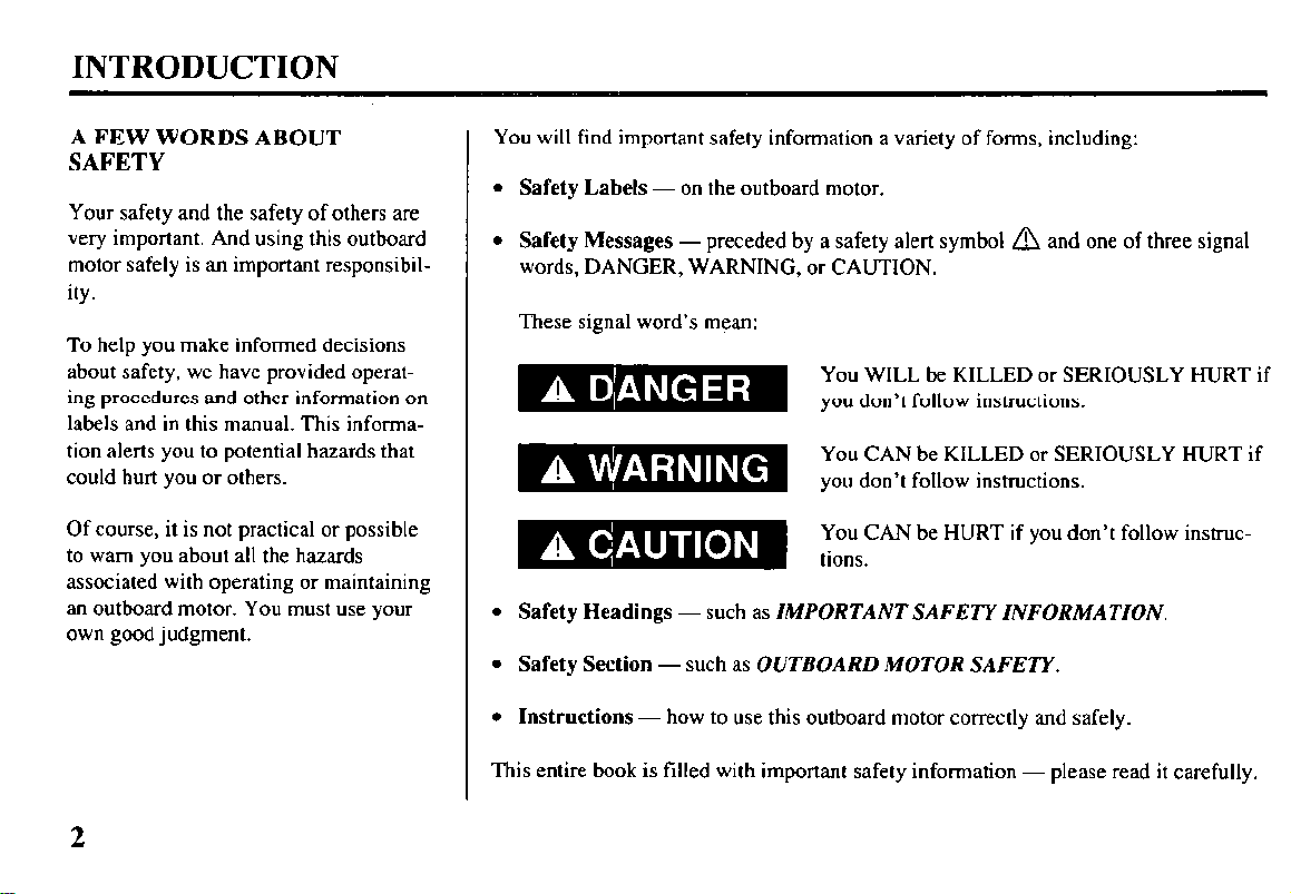
You will find important safety information a variety of forms, including:
l Safety Labels - on the outboard motor.
.
Safety Messages - preceded by a safety alert symbol A and one of three signal
words, DANGER, WARNING, or CAUTION.
These signal word’s mean:
You WILL be KILLED or SERIOUSLY HURT if
you don’t follow instructions.
You CAN be KILLED or SERIOUSLY HURT if
you don’t follow instructions.
l Safety Headings - such as IMPORTANT SAFETY INFORMATION.
l Safety Section - such as OUTBOARD MOTOR SAFETY.
l Instructions - how to use this outboard motor correctly and safely.
This entire book is filled with important safety information - please read it carefully.
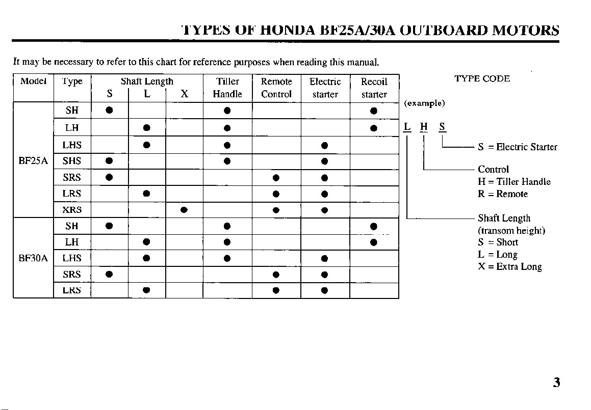
TYPES OF HONDA BF25A/30A OUTBOARD MOTORS
It may be necessary to refer to this chart for reference purposes when reading this manual.
TYPE CODE
I S = Electric Starter
Control
H = Tiller Handle
R = Remote
Shaft Length
(transom height)
S = Short
L = Long
X = Extra Long
3
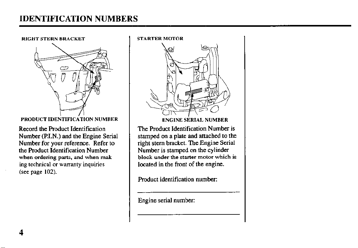
IDENTIFICATION NUMBERS
RIGHT STERN BRACKET
PRODUCT IDENTIFICiTION NUMBER
Record the Product Identification
Number (R1.N.) and the Engine Serial
Number for your reference. Refer to
the Product Identification Number
when ordering parts, and when making technical or warranty inquiries
(see page 102).
STARTER MOTOR
ENGINE SERIAL NUMBER
The Product Identification Number is
stamped on a plate and attached to the
right stem bracket. The Engine Serial
Number is stamped on the cylinder
block under the starter motor which is
located in the front of the engine.
Product identification number:
Engine serial number:
CONTENTS
1. OUTBOARD MOTOR SAFETY
IMPORTANT SAFETY INFORMATION
SAFETY LABEL LOCATIONS
COMPONENT IDENTIFICATION
2.
...............................
............................
...............
3. CONTROLS
TILLER HANDLE TYPE
Engine Start Button
Gearshift Lever
Choke Knob..
Throttle Grip..
Throttle Opening Indicator
Throttle Friction
Engine Stop Switch
Emergency Stop Switch Lanyard
Oil Pressure Indicator Light
.................................................... 13
........................................................... 13
..............................................................
............................................................. 14
.........................................
Knob ............................................... 14
....................................................
...............................
.......................................
Recoil Starter.. ............................................................
REMOTE CONTROL TYPE
Remote Control Lever
Neutral Release Lever
Ignition Switch
Emergency Stop Switch Lanyard
Choke/Fast Idle Lever
Manual Choke Knob
Oil Pressure Indicator Light/Buzzer..
Overheat Indicator Light/Buzzer..
................................................
................................................
........................................................... 18
...............................
................................................ 20
..................................................
.........................
..............................
7
9
10
13
14
15
15
16
16
17
18
19
20
21
21
CONTROLS & INSTRUMENTS (common)
Tilt Lever
Trim
Anode
Cooling
Water
Transom Angle Adjusting Rod
Fuel Cap/Gauge/Vent Knob
Engine Over-Rev Limiter..
....................................................................
Tab.. ...................................................................
Metal ...............................................................
System Indicator..
.........................................
Intakes.. ............................................................
..................................
.......................................
.........................................
4. INSTALLATION
Installation
Installation
Installation
Motor
Engine Cover Removal
..................................................................
Position ....................................................
Height ......................................................
Attachment ......................................................
Installation
...........................
5. PRE-OPERATION CHECKS
Engine
Fuel
Fuel
Oxygenated
Propeller and Cotter Pin
Oil ..................................................................
Level ...................................................................
Recommendations ..............................................
Fuels .......................................................
.............................................
Steering Friction Adjustment (common).
Remote Control Friction Adjustment
.........................
Other Checks
.................................................................
Hose
l
Fuel
l
Stern Bracket/Clamp/Screws
...................................
...................
22
22
23
23
23
24
25
25
26
26
26
27
28
29
30
3 1
32
33
33
34
34
34
5
CONTENTS
l
Tool Kit ....................................................................
l
.......................................................................
Anode
6. STARTING THE ENGINE
Fuel Tank and Vent Knob .......................................... 35
Fuel Line Connection
.................................................
Starting the Engine (TILLER HANDLE TYPE)
Starting the Engine (REMOTE CONTROL TYPE). ... 41
Emergency Starting
....................................................
Troubleshooting Starting Problems ............................
7. OPERATION
Break-in Procedure
.....................................................
TILLER HANDLE TYPE
Gear Shifting
Steering
.............................................................. 51
.......................................................................
Cruising ...................................................................... 52
REMOTE CONTROL TYPE
Gear Shifting .............................................................. 53
Cruising ...................................................................... 54
Tilting Motor
Tilt Lever.. .................................................................. 55
Trim Tab Adjustment ................................................. 58
MOTOR PROTECTION SYSTEM
Engine Oil Pressure and
Overheat Warning System
.........................................
Over-Rev Limiter ....................................................... 61
Anode
.........................................................................
High Altitude Operation ............................................. 62
.......
34
34
35
37
44
49
50
52
59
61
8. STOPPING THE ENGINE
TILLER HANDLE TYPE
REMOTE CONTROL TYPE
9. TRANSPORTING
.....................................................
10. CLEANING AND FLUSHING
11. MAINTENANCE
.......................................................
.......................................
..................................
.................................
THE IMPORTANCE OF MAINTENANCE
MAINTENANCE SAFETY
....................................
EMISSION CONTROL SYSTEM INFORMATION
STAR LABEL
Tool Kit and Spare Parts
MAINTENANCE SCHEDULE
Engine Oil
Gear Oil
.................................................................. 73
..........................................
..............................
................................................................
....................................................................
Spark Plugs ..............................................................
Battery (not included)
Lubrication
...............................................................
Engine Fuel Filter
Fuel Tank and Filter
Fuse Replacement
Propeller
...................................................................
Submerged Motor
12. STORAGE
.................................................................
13. TROUBLESHOOTING
14. SPECIFICATIONS
15. WARRANTY SERVICE
16. WIRING DIAGRAM
17. INDEX
.......................................................................
..............................................
....................................................
.................................................
....................................................
....................................................
.............................................
....................................................
...........................................
.................................................
63
65
66
67
69
.......... 69
69
...... 70
;i
78
;:
83
84
86
;:
90
;:
95
97
102
103
106
6
1. OUTBOARD MOTOR SAFETY
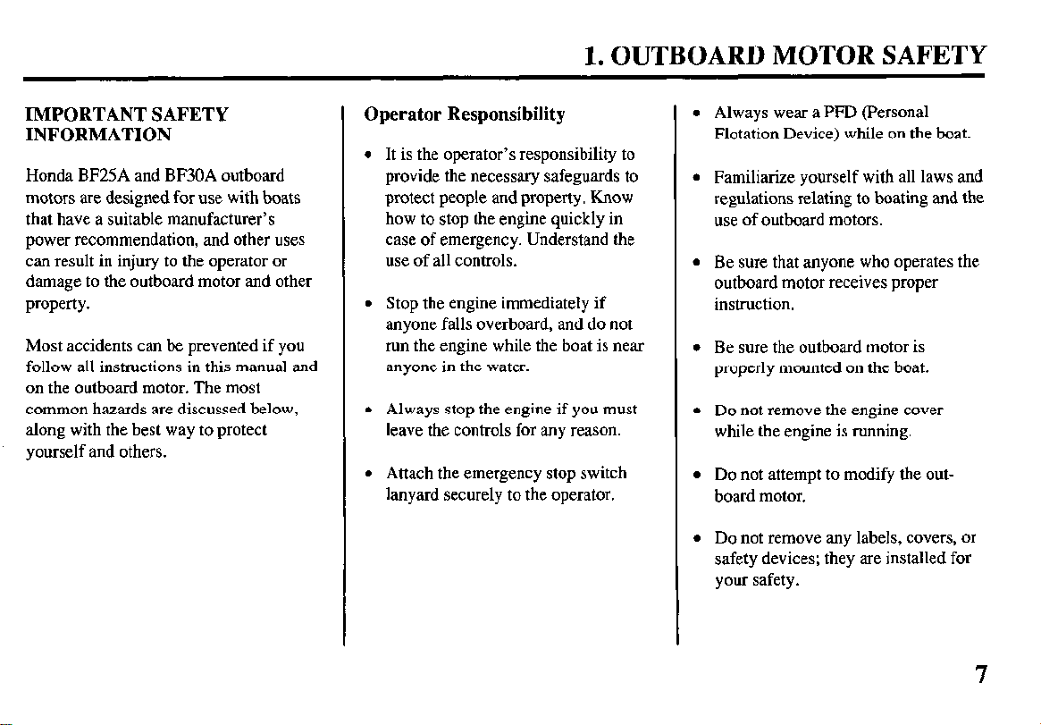
IMPORTANT SAFETY INFORMATION
Honda BF25A and BF30A outboard
motors are designed for use with boats
that have a suitable manufacturer’s
power recommendation, and other uses
can result in injury to the operator or
damage to the outboard motor and other
property.
Most accidents can be prevented if you
follow all instructions in this manual and
on the outboard motor. The most
common hazards are discussed below,
along with the best way to protect
yourself and others.
Operator Responsibility
l It is the operator’s responsibility to
provide the necessary safeguards to
protect people and property. Know
how to stop the engine quickly in
case of emergency. Understand the
use of all controls.
l Stop the engine immediately if
anyone falls overboard, and do not
run the engine while the boat is near
anyone in the water.
l Always stop the engine if you must
leave the controls for any reason.
l Attach the emergency stop switch
lanyard securely to the operator.
Always wear a PFD (Personal
Flotation Device) while on the boat.
Familiarize yourself with all laws and
regulations relating to boating and the
use of outboard motors.
Be sure that anyone who operates the
outboard motor receives proper
instruction.
Be sure the outboard motor is
properly mounted on the boat.
Do not remove the engine cover
while the engine is running.
Do not attempt to modify the outboard motor.
Do not remove any labels, covers, or
safety devices; they are installed for
your safety.
1. OUTBOARD MOTOR SAFETY
Refuel With Care
l Gasoline is extremely flammable, and
gasoline vapor can explode. Refuel
outdoors, in a well-ventilated area,
with the engine stopped. Never
smoke near gasoline, and keep other
flames and sparks away.
l Remove any portable fuel tank from
the boat for refueling. Keep the
portable fuel tank away from the
battery or other potential spark
sources.
l Refuel carefully to avoid spilling
fuel. Avoid overfilling the fuel tank.
l After refueling, tighten the filler cap
securely. If any fuel is spilled, make
sure the area is dry before starting the
engine.
Carbon Monoxide Hazard
Exhaust gas contains poisonous carbon
monoxide. Avoid inhalation of exhaust
gas. Never run the engine in a closed
garage or confined area.
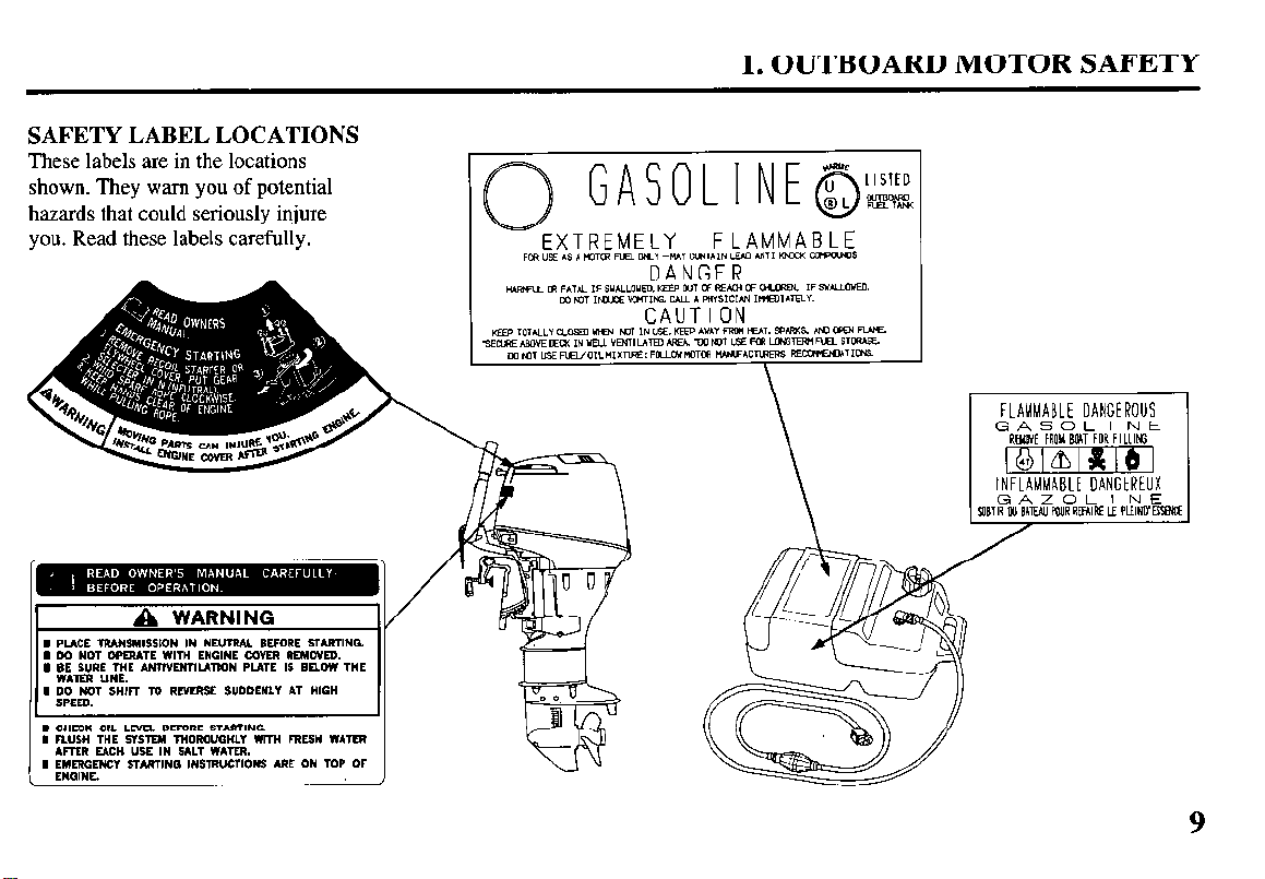
SAFETY LABEL LOCATIONS
These labels are in the locations
shown. They warn you of potential
hazards that could seriously injure
you. Read these labels carefully.
I PUCE lRANSM,SS,ON IN nE”mAl BEFORE STARTING.
I 00 NOT OPERATE WITH ENGINE COVER REMOVED.
I GE SVRE THE A.NTIVENTIUTION PLATE IS BELOW THE
I 00 NOT SHIFT TO
REVERSE
SUDDENLY AT HIGH
1. OUTBOARD MOTOR SAFETY
FLAMMABLE
CONTAIN LEAD ANTI KNMX aypaJNs
I CHECK OIL LEVEL BEFORE STARTING.
I RUSH THE
ARER EACR USE IN SALT WATER.
I ~GM~CY STARTING INSTRUCTIONS ARE ON TOP OF
SYSTEM
THOROUGHLY WITH FRESH WAYER
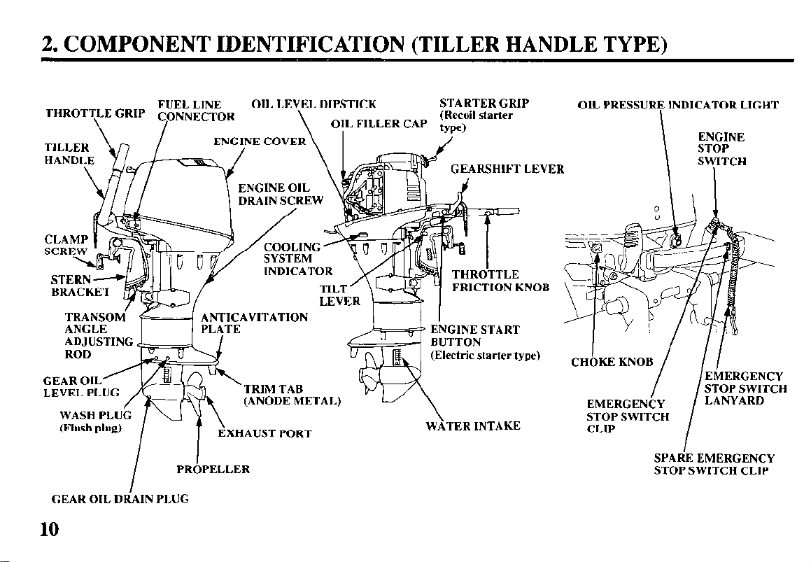
2. COMPONENT IDENTIFICATION
(TILLER HANDLE TYPE)
FUEL LINE
CLA
SCR
I
GEAR OIL DIiAIN PLUG
I
PROPELLER
OIL LEVEL DIPSTICK
ENGINE OIL
DRAIN SCREW
, “R
TAL)
STARTER GRIP
THRdTTLE
FRICTION KNOB \ --.
ENGINE START
(Electric starter type)
WATER INTAKE
OIL PRESSURE INDICATOR LIGHT
---.
Irl\ -
9 \
c--
EtiERGENCY
EMERGENCY
STOP SWITCH
CLIP
I
STOP SWITCH
LANYARD
I
SPAdE EMERGENCY
STOP SWITCH CLIP
10
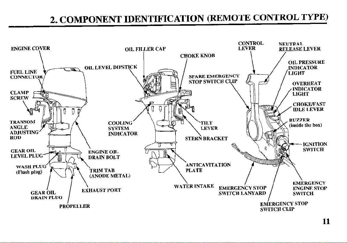
2. COMPONENT IDENTIFICATION
(REMOTE CONTROL TYPE)
ENGINE COVER
\
ADJUSTING’
ROD
GEAR OIL
LEVEL PLUG’r-fiy& i;i;;ii
jiILZ&. !-NUN, OIL
I
I
GEAR OIL
DRAIN PLUG
PROPELLER
\
. \.
I \
\
EXHAUST PORT
I
, DIPSTICK
COOLING
SYSTEM
INDICATOR
_..---.-- -
N BOLT
1 TAB
DE METAL)
OIL FILLER CAP
CONTROL
LEVER
CHOKE KNOB
I
SPARE EMERGENCY
STOP SWITCH C
TILT
LEVER
RP
A“UPT
\
WATER INTAKE EMERGENCY STOP
SWITCH LANYARD
K j Ill L!trsEAn
/
EMERGENCY STOP
SWITCH CLIP
NEUTRAL
EM\ERGENCY
ENGINE STOP
SWITCH
I
11
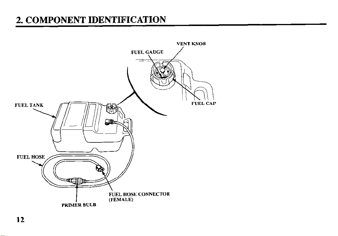
2. COMPONENT IDENTIlFICATION
FUEL GAUGE
FUEL T
FUEL
VENT KNOB
/
12
I
PRIMER BULB
FUEL HOSE CONNECTOR
(FEMALE)
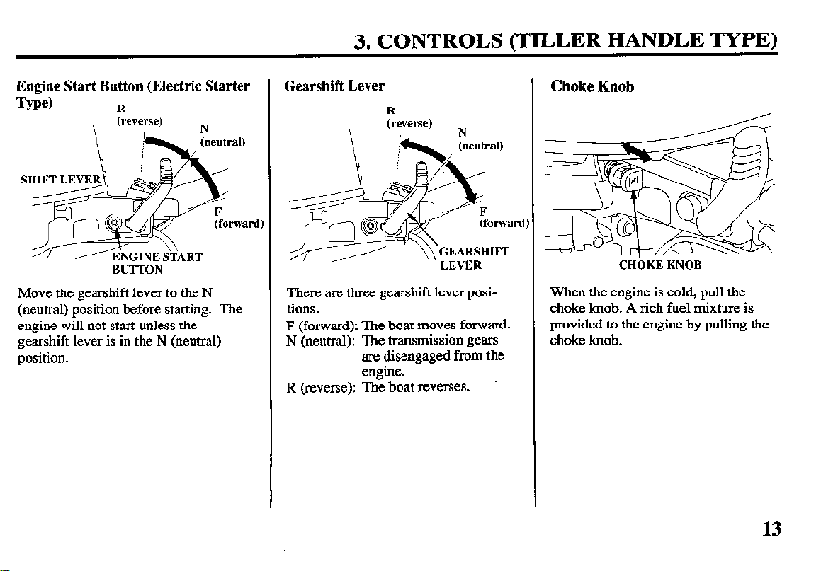
3. CONTROLS (TILLER HANDLE TYPE)
Engine Start Button (Electric Starter
Type)
R
BUTTON
Move the gearshift lever to the N
(neutral) position before starting. The
engine will not start unless the
gearshift lever is in the N (neutral)
position.
Gearshift Lever
R
(reverse)
\
---/ /----
N
’ ’ LEVER
There are three gearshift lever positions.
F (forward): The boat moves forward.
N (neutral): The transmission gears
are disengaged from the
engine.
R (reverse): The boat reverses.
Choke Knob
CHbKE KNOB
When the engine is cold, pull the
choke knob. A rich fuel mixture is
provided to the engine by pulling the
choke knob.
13
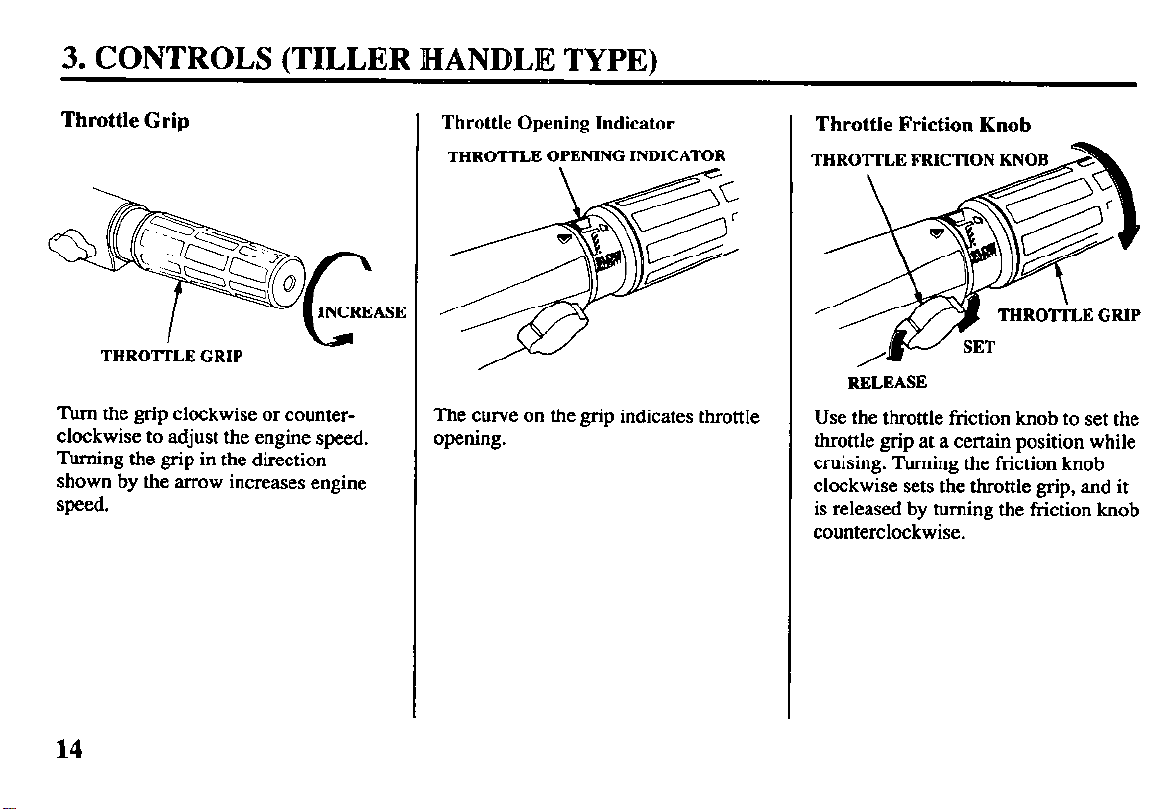
3. CONTROLS (TILLER HANDLIE TYPE)
Throttle Grip
THRO’ITLE GRIP
Turn the grip clockwise or counterclockwise to adjust the engine speed.
Turning the grip in the direction
shown by the arrow increases engine
speed.
Throttle Opening Indicator
THROTTLE OPENING INDICATOR
The curve on the grip indicates throttle
opening.
Throttle Friction Knob
RELEASE
Use the throttle friction knob to set the
throttle grip at a certain position while
cruising. Turning the friction knob
clockwise sets the throttle grip, and it
is released by turning the friction knob
counterclockwise.
14
3. CONTROLS (TILLER HANDLE TYPE)
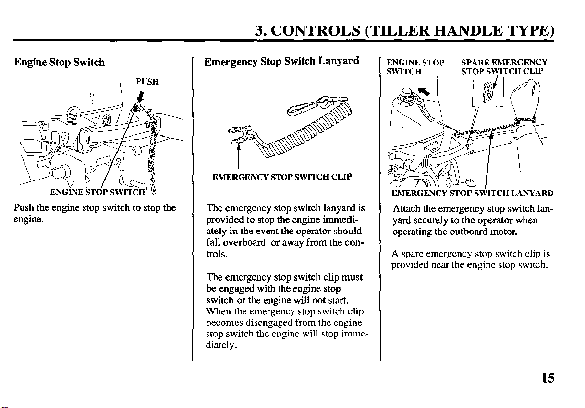
Engine Stop Switch
PUSH
Push the engine stop switch to stop the
engine.
Emergency Stop Switch Lanyard
EMERGENCY STOP SWITCH CLIP
The emergency stop switch lanyard is
provided to stop the engine immediately in the event the operator should
fall overboard or away from the controls.
The emergency stop switch clip must
be engaged with the engine stop
switch or the engine will not start.
When the emergency stop switch clip
becomes disengaged
stop switch the engine will stop immediately.
from the engine
ENGINE STOP
SWITCH
EMERGENCY STOP SWITCH LANYARD
SPARE EMERGENCY
STOP SWITCH CLIP
Attach the emergency stop switch lanyard securely to the operator when
operating the outboard motor.
A
spare emergency stop switch clip is
provided near the engine stop switch.
15
3. CONTROLS (TILLER HANDLE TYPE)
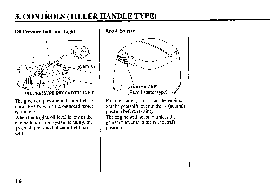
Oil Pressure Indicator Light
\ I
OIL PRkSURE INDICATOR LIGHT
The green oil pressure indicator light is
normally ON when the outboard motor
is running.
When the engine oil level is low or the
engine lubrication system is faulty, the
green oil pressure indicator light turns
OFF.
Recoil Starter
’ STARTER GRIP
,a ’
’ (Recoil starter type)
Pull the starter grip to start the engine.
Set the gearshift lever in the N (neutral)
position before starting.
The engine will not start unless the
gearshift lever is in the N (neutral)
position.
16
3. CONTROLS (REMOTE CONTROL TYPE)
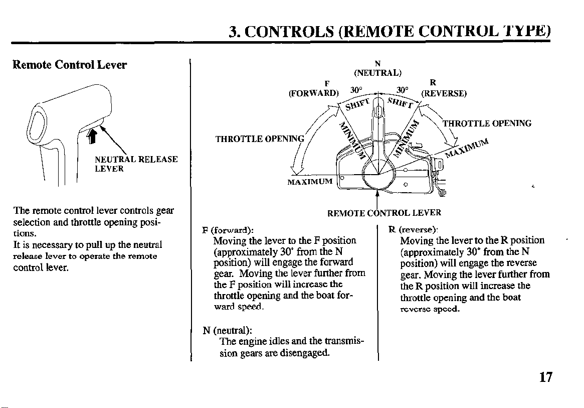
Remote Control Lever
The remote control lever controls gear
selection and throttle opening positions.
It is necessary to pull up the neutral
release lever to operate the remote
control lever.
THROTTLE
REMOTE CONTROL LEVER
F (forward):
Moving the lever to the F position
(approximately 30” from the N
position) will engage the forward
gear. Moving the lever further from
the F position will increase the
throttle opening and the boat forward speed.
N (neutral):
The engine idles and the transmission gears are disengaged.
(NEUhAL)
I
OPENING
R (reverse):
Moving the lever to the R position
(approximately 30” from the N
position) will engage the reverse
gear. Moving the lever further from
the R position will increase the
throttle opening and the boat
reverse speed.
.
17
3. CONTROLS (REMOTE CONTROL TYPE)
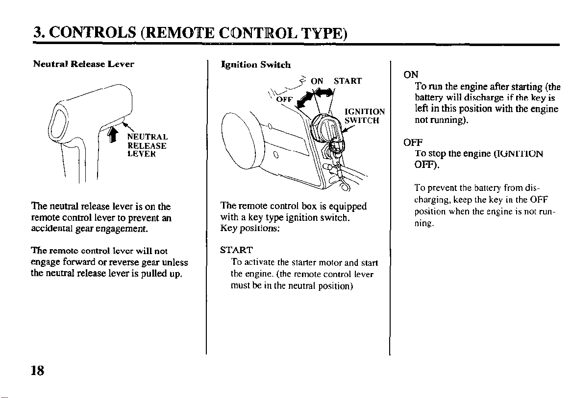
Neutral Release Lever
The neutral release lever is on the
remote control lever to prevent an
accidental gear engagement.
The remote control lever will not
engage forward or reverse gear unless
the neutral release lever is pulled up.
Ignition Switch
+ ON START
The remote control box is equipped
with a key type ignition switch.
Key positions:
START
To activate the starter motor and start
the engine. (the remote control lever
must be in the neutral position)
ON
To run
battery
the engine after starting (the
will discharge if the key is
left in this position with the engine
not running).
OFF
To stop the engine (IGNITION
OFF).
To prevent
the battery
from dis-
charging, keep the key in the OFF
position when the engine is not running.
18
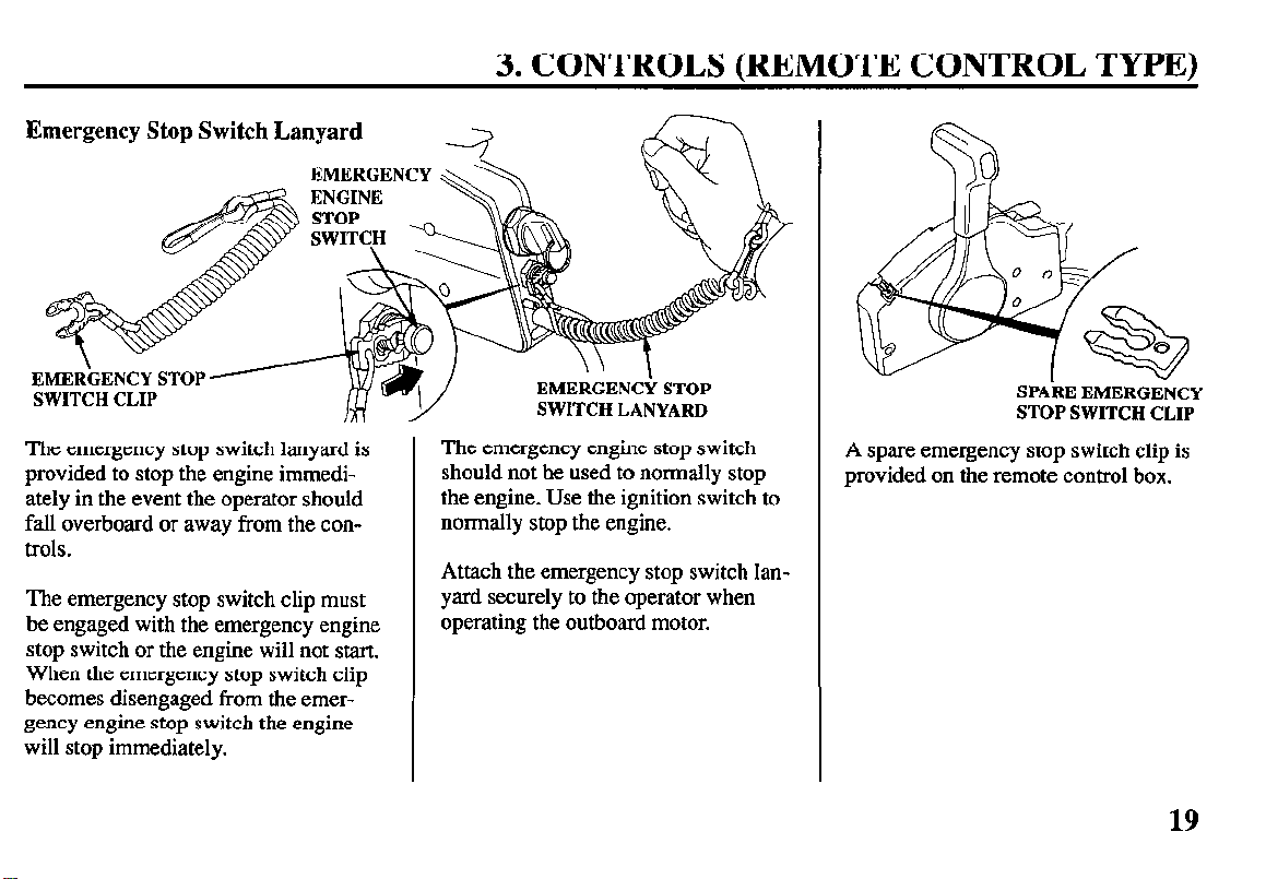
Emergency Stop Switch Lanyard
3. CONTROLS (REMOTE CONTROL TYPE)
EMER\GENCY STOP ’
SWITCH CLIP
The emergency stop switch lanyard is
provided to stop the engine immediately in the event the operator should
fall overboard or away from the controls.
The emergency stop switch clip must
be engaged with the emergency engine
stop switch or the engine will not start.
When the emergency stop switch clip
becomes disengaged from the emergency engine stop switch the engine
will stop immediately.
SWITCH LANYARD
The emergency engine stop switch
should not he used to normally stop
the engine. Use the ignition switch to
normally stop the engine.
Attach the emergency stop switch lanyard securely to the operator when
operating the outboard motor.
SPARE EMERGENCY
STOP SWITCH CLIP
A spare emergency stop switch clip is
provided on the remote control box.
19
3. CONTROLS (REMOTE CONTROL TYPE)
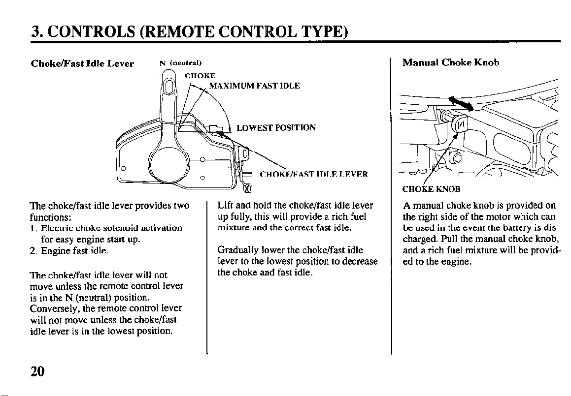
Choke/Fast Idle Lever
N (neutral)
CHOKE
The choke/fast idle lever provides two
functions:
1. Electric choke solenoid activation
for easy engine start up.
2. Engine fast idle.
The choke/fast idle lever will not
move unless the remote control lever
is in the N (neutral) position.
Conversely, the remote control lever
will not move unless the choke/fast
idle lever is in the lowest position.
XIMUM FAST IDLE
LOWEST POSITION
AST IDLE
LEVER
Lift and hold the choke/fast idle lever
up fully, this will provide a rich fuel
mixture and the correct fast idle.
Gradually lower the choke/fast idle
lever to the lowest position to decrease
the choke and fast idle.
Manual Choke Knob
CHOkE KNOB
A manual choke knob is provided on
the right side of the motor which can
be used in the event the battery is discharged. Pull the manual choke knob,
and a rich fuel mixture will be provided to the engine.
20
3. CONTROLS (REMOTE CONTROL TYPE)
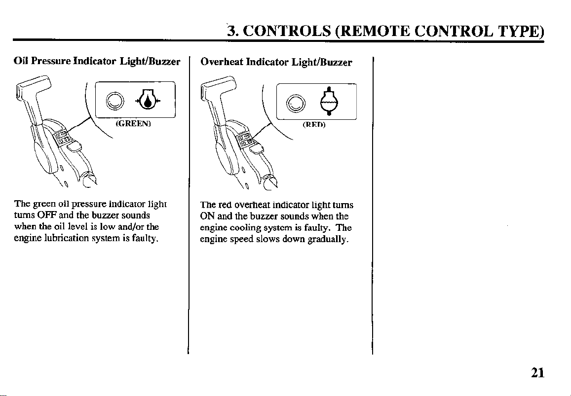
Oil Pressure Indicator Light/Buzzer 1
The green oil pressure indicator light
turns OFF and the buzzer sounds
when the oil level is low and/or the
engine lubrication system is faulty.
Overheat Indicator Light/Buzzer
The red overheat indicator light turns
ON and the buzzer sounds when the
engine cooling system is faulty. The
engine speed slows down gradually.
21
3. CONTROLS dk INSTRUMENTS (common)
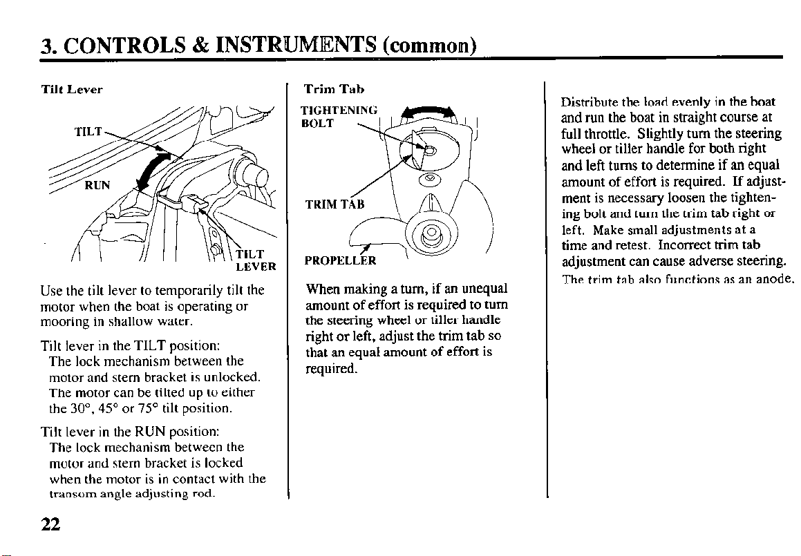
Tilt Lever
LEVER
Use the tilt lever to temporarily tilt the
motor when the boat is operating or
mooring in shallow water.
Tilt lever in the TILT position:
The lock mechanism between the
motor and stern bracket is unlocked.
The motor can be tilted up to either
the 30”, 45” or 75” tilt position.
Tilt lever in the RUN position:
The lock mechanism between the
motor and stern bracket is locked
when the motor is in contact with the
transom angle adjusting rod.
Trim Tab
\
When making a turn, if an unequal
amount of effort is required to turn
the steering wheel or tiller handle
right or left, adjust the trim tab so
that an equal amount of effort is
required.
Distribute the load evenly in the boat
and run the boat in straight course at
full throttle. Slightly turn the steering
wheel or tiller handle for both right
and left turns to determine if an equal
amount of effort is required. If adjustment is necessary loosen the tightening bolt and turn the trim tab right or
left. Make small adjustments at a
time and retest. Incorrect trim tab
adjustment can cause adverse steering.
The trim tab also functions as an anode.
22
3. CONTROLS & INSTRUMENTS (common)
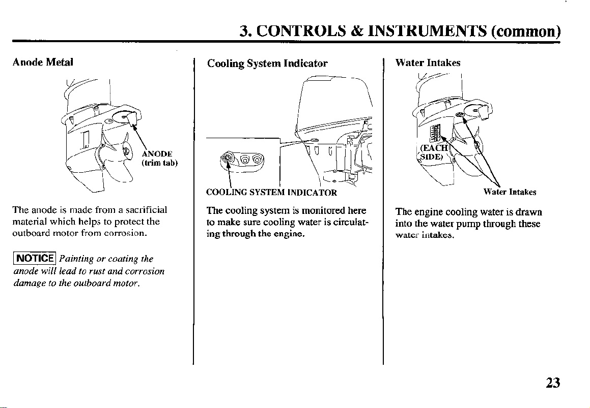
Anode Metal
The anode is made from a sacrificial
material which helps to protect the
outboard motor from corrosion.
-1 Painting or coating the
anode will lead to rust and corrosion
damage to the outboard motor.
Cooling System Indicator
COOiING SYSTEM INDICATOR
The cooling system is monitored here
to make sure cooling water is circulating through the engine.
Water Intakes
Waier Intakes
The engine cooling water is drawn
into the water pump through these
water intakes.
23
3. CONTROLS & INSTRUMENTS (common)
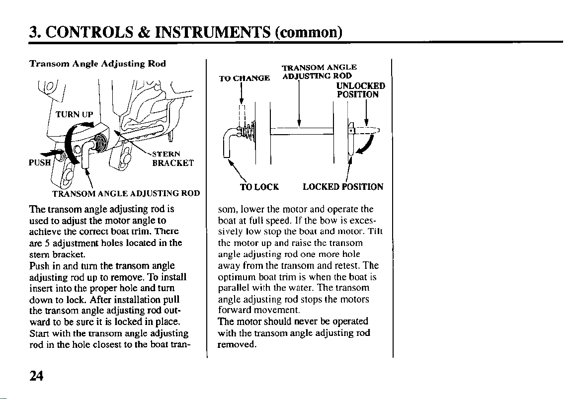
Transom Angle Adjusting Rod
TRANSOM ANGLE ADJUSTING ROD
The transom angle adjusting rod is
used to adjust the motor angle to
achieve the correct boat trim. There
are 5 adjustment holes located in the
stem bracket.
Push in and turn the transom angle
adjusting rod up to remove. To install
insert into the proper hole and turn
down to lock. After installation pull
the transom angle adjusting rod outward to be sure it is locked in place.
Start with the transom angle adjusting
rod in the hole closest to the boat tran-
TO CHANGE ADJUSTING ROD
TO LOCK LOCKED POSITION
TRANSOM ANGLE
I
-;
UNLOCKED
POSITION
I
---
.
--A’
J
som, lower the motor and operate the
boat at full speed. If the bow is excessively low stop the boat and motor. Tilt
the motor up and raise the transom
angle adjusting rod one more hole
away from the transom and retest. The
optimum boat trim is when the boat is
parallel with the water. The transom
angle adjusting rod stops the motors
forward movement.
The motor should never be operated
with the transom angle adjusting rod
removed.
24
3. CONTROLS & INSTRUMENTS (common)
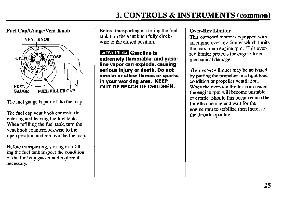
Fuel Cap/Gauge/Vent Knob
VENT KNOB
GAUGii
FUEL FiLLEli CAP
The fuel gauge is part of the fuel cap.
The fuel cap vent knob controls air
entering and leaving the fuel tank.
When refilling the fuel tank, turn the
vent knob counterclockwise to the
open position and remove the fuel cap.
Before transporting, storing or refilling the fuel tank inspect the condition
of the fuel cap gasket and replace if
necessary.
Before transporting or storing the fuel
tank turn the vent knob fully clockwise to the closed position.
I -
m Gasoline is
extremely flammable, and gaso-
line vapor can explode, causing
serious injury or death. Do not
smoke or allow flames or sparks
in your working area. KEEP
OUT OF REACH OF CHILDREN.
Over-Rev Limiter
This outboard motor is equipped with
an engine over-rev limiter which limits
the maximum engine rpm. This overrev limiter protects the engine from
mechanical damage.
The over-rev limiter may be activated
by putting the propeller in a light load
condition or propeller ventilation.
When the over-rev limiter is activated
the engine rpm will become unstable
or erratic. Should this occur reduce the
throttle opening and wait for the
engine rpm to stabilize then increase
the throttle opening.
25
4. INSTALLATION
Installation
It is your responsibility to choose a
boat suitable for the motor.
DO NOT OVERPOWER THE BOAT
Do not install an outboard motor that
exceeds the recommended maximum
horsepower for the boat. Refer to the
boat certification plate for the maxi-
mum recommended horsepower for the
boat. For most boat applications, the
motor should have a horsepower which
provides 80% of the maximum recommended horsepower for the boat. If the
certification plate information is not
available, contact the boat dealer.
The BF25A/30A must be installed on
transoms which have the following
minimum or maximum thickness.
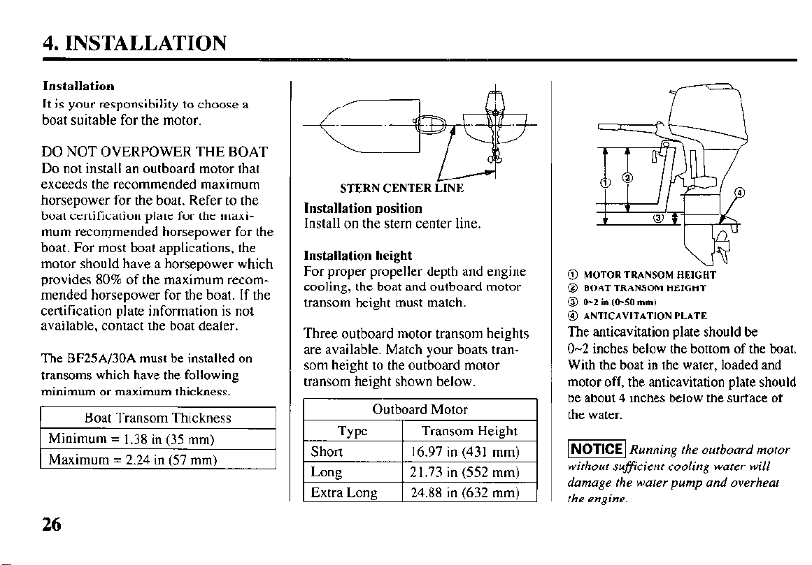
STERN CENTER LINE
Installation position
Install on the stern center line.
Installation height
For proper propeller depth and engine
cooling, the boat and outboard motor
transom height must match.
Three outboard motor transom heights
are available. Match your boats transom height to the outboard motor
transom height shown below.
Outboard Motor
@ MOTOR TRANSOM HEIGHT
@ BOAT TRANSOM HEIGHT
0 O-2inW50mm)
@ ANTICAVITATION PLATE
The anticavitation plate should be
O-2 inches below the bottom of the boat.
With the boat in the water, loaded and
motor off, the anticavitation plate should
be about 4 inches below the surface of
the water.
-1 Running the outboard motor
without suficient cooling water will
damage the water pump and overheat
the engine.
26
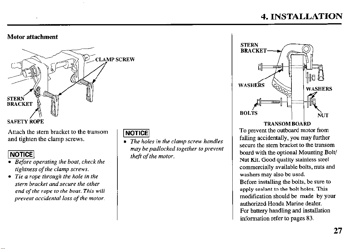
Motor attachment
4. INSTALLATION
SCREW
SAFETY kOiE
Attach the stem bracket to the transom
and tighten the clamp screws.
l Before operating the boat, check the
tightness of the clamp screws.
l Tie a rope through the hole in the
stern bracket and secure the other
end of the rope to the boat. This will
prevent accidental loss of the motor.
l The holes in the clamp screw handles
may be padlocked together to prevent
theft of the motor.
BOLiS
TRANSOM BOAkD
I I
%JT
To prevent the outboard motor from
falling accidentally, you may further
secure the stem bracket to the transom
board with the optional Mounting Bolt/
Nut Kit. Good quality stainless steel
commercially available bolts, nuts and
washers may also be used.
Before installing the bolts, be sure to
apply sealant to the bolt holes. This
modification should be made by your
authorized Honda Marine dealer.
For battery handling and installation
information refer to pages 83.
27
4. INSTALLATION
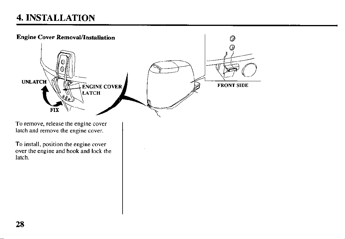
Engine Cover Removal/Installation
UNLAT
To remove, release the engine cover
latch and remove the engine cover.
To install, position the engine cover
over the engine and hook and lock the
latch.
28
FRONT SIDE
 Loading...