

Honda BF200A, BF225A User Manual
BF200A·BF225A
Includes US and Canadian Models
The engine exhaust from this
product contains chemicals
known to the State of California to
cause cancer, birth defects, or
other reproductive harm.
Keep this Owner’s Manual handy, so you can refer to it at any time. This Owner’s
Manual is considered a permanent part of the outboard motor and should remain with
the outboard motor if resold.
2011 Honda Motor Co., Ltd. All Rights Reserved
The information and specifications included in this publication were in effect at the
time of approval for printing. Honda Motor Co., Ltd. reserves the right, however, to
discontinue or change specifications or design at any time without notice and without
incurring any obligation whatever. No part of this publication may be reproduced
without written permission.
−

INTRODUCTION
Congratulations on your selection of
a Honda outboard motor. We are
certain you will be pleased with your
purchase of one of the finest
outboard motors on the market.
We want to help you get the best
results from your new outboard
motor and to operate it safely. This
manual contains information on how
to do that; please read it carefully.
find information preceded by a
symbol. That information
is intended to help you avoid damage
to your outboard motor, other
property, or the environment.
We suggest you read the warranty
policy to fully understand its
coverage and your responsibilities of
ownership.
When your outboard motor needs
scheduled maintenance, keep in mind
that your Honda Marine dealer is
specially trained in servicing Honda
outboard motors. Your Honda
Marine dealer is dedicated to your
satisfaction and will be pleased to
answer your questions and concerns.As you read this manual you will
Best Wishes,
Honda Motor Co., Ltd.
1
INTRODUCTION
A FEW WORDS ABOUT SAFETY
Your safety and the safety of others
are very important. And using this
outboard motor safely is an important
responsibility.
To help you make informed
decisions about safety, we have
provided operating procedures and
other information on labels and in
this manual. This information alerts
you to potential hazards that could
hurt you or others.
Of course, it is not practical or
possible to warn you about all the
hazards associated with operating or
maintaining an outboard motor. You
must use your own good judgment.
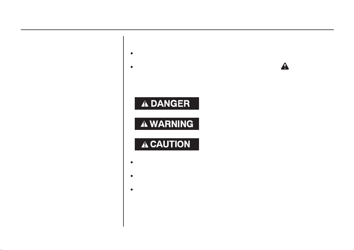
You will find important safety information in a variety of forms, including:
Safety Labels
Safety Messages
three signal words, DANGER, WARNING, or CAUTION.
These signal words mean:
Safety Headings
Safety Section
Instructions
This entire book is filled with important safety information please read it
carefully.
−
on the outboard motor.
−
preceded by a safety alert symbol and one of
You WILL be KILLED or SERIOUSLY
HURT if you don’t follow instructions.
You CAN be KILLED or SERIOUSLY
HURT if you don’t follow instructions.
You CAN be HURT if you don’t follow
instructions.
−
such as
−
such as
−
how to use this outboard motor correctly and safely.
IMPORTANT SAFETY INFORMATION.
OUTBOARD MOTOR SAFETY.
−
2

CONTENTS
...................................OUTBOARD MOTOR SAFETY . 7
................IMPORTANT SAFETY INFORMATION . 7
..................................SAFETY LABEL LOCATION . 9
..................................CONTROLS AND FEATURES . 12
CONTROL AND FEATURE IDENTIFICATION
..................................................................CODES . 12
..............................................................CONTROLS . 18
Side-Mount Type
......................................................Ignition Switch . 18
Emergency Stop Switch Clip and Emergency
.......................................................Stop Switch . 19
..........................Gearshift/Throttle Control Lever . 19
.......................................................Fast Idle Lever . 21
Panel-Mount Type
......................................................Ignition Switch . 21
Emergency Stop Switch Clip and Emergency
.......................................................Stop Switch . 22
..........................Gearshift/Throttle Control Lever . 23
.....................................................Fast Idle Button . 24
....COMPONENT AND CONTROL LOCATIONS . 13
Top-Mount Type
......................................................Ignition Switch . 25
Emergency Stop Switch Clip and Emergency
.......................................................Stop Switch . 25
..........................Gearshift/Throttle Control Lever . 26
.....................................................Fast Idle Button . 27
Common Controls
........................................Power Trim/Tilt Switch . 28
..................................................Power Tilt Switch . 29
.............................................Manual Relief Valve . 29
.....................................................Tilt Lock Lever . 29
..............................................Engine Cover Latch . 30
................................................................Trim Tab . 30
.......................................................INSTRUMENTS . 30
.........................Trim Meter (optional equipment) . 30
.........................Tachometer (optional equipment) . 31
.............Digital Tachometer (optional equipment) . 31
...........Digital Speedometer (optional equipment) . 31
......................................NMEA Interface Coupler . 32
3

CONTENTS
...........................................................INDICATORS . 33
...................................Alternator (ACG) Indicator . 33
...........................................Malfunction Indicator . 33
............................................Oil Pressure Indicator . 34
.................................................Overheat Indicator . 34
.....................................Cooling System Indicator . 35
................................................OTHER FEATURES . 35
........................................Water Separator Buzzer . 35
...........................................................Rev Limiter . 36
...................................................................Anodes . 36
.................................................Fuel Priming Bulb . 36
................................................BEFORE OPERATION . 37
IS YOUR OUTBOARD MOTOR
..................................................READY TO GO? . 37
.........ARE YOU READY TO GET UNDERWAY? . 37
................................................................OPERATION . 39
....................SAFE OPERATING PRECAUTIONS . 39
.......................................BREAK-IN PROCEDURE . 39
.......................................................FUEL PRIMING . 40
...............INFREQUENT OR OCCASIONAL USE . 40
......................................STARTING THE ENGINE . 41
..................................................Side-Mount Type . 41
.................................................Panel-Mount Type . 44
...................................................Top-Mount Type . 46
.......................................STOPPING THE ENGINE . 49
................................Emergency Engine Stopping . 49
.......................................Normal Engine Stopping . 50
GEARSHIFT AND
..............................THROTTLE OPERATION . 51
..................................................Side-Mount Type . 51
.................................................Panel-Mount Type . 51
...................................................Top-Mount Type . 51
...............................................................STEERING . 53
................................................................CRUISING . 53
........................SHALLOW WATER OPERATION . 55
...............MOORING, BEACHING, LAUNCHING . 56
4

CONTENTS
.....................................MAINTENANCE SAFETY . 59
...............................MAINTENANCE SCHEDULE . 61
....................................TRIM TAB ADJUSTMENT . 63
....................................MANUAL RELIEF VALVE . 64
ENGINE COVER REMOVAL AND
..................................................INSTALLATION . 64
............................................Engine Oil Level Check . 65
....................................................Engine Oil Change . 65
.......................................................Oil Filter Change . 66
..................................Engine Oil Recommendations . 68
.....................................................Lubrication Points . 69
..............SERVICING YOUR OUTBOARD MOTOR . 58
...........THE IMPORTANCE OF MAINTENANCE . 58
...................TOOL KIT and OWNER’S MANUAL . 60
....................................................Spark Plug Service . 70
.............................................................REFUELING . 73
...............................FUEL RECOMMENDATIONS . 74
...................Fuel Filter Inspection and Replacement . 75
...................Water Separator Inspection and Service . 77
..................................................Anode Replacement . 79
..............................................Propeller Replacement . 80
.............................................Inspect After Operating . 81
....................................CLEANING AND FLUSHING . 82
..............................................Cleaning and Flushing . 82
....................................................................STORAGE . 84
........................................................................Fuel . 84
.............................................................Engine Oil . 86
................HOISTING THE OUTBOARD MOTOR . 87
...................................STORAGE PRECAUTIONS . 87
...............................REMOVAL FROM STORAGE . 88
5

CONTENTS
........................................................TRANSPORTING . 89
WITH OUTBOARD MOTOR
......................................INSTALLED ON BOAT . 89
WITH OUTBOARD MOTOR
..................................REMOVED FROM BOAT . 89
..................................ENGINE WILL NOT START . 90
HARD STARTING OR STALLS AFTER
...........................................................STARTING . 93
...........................................ENGINE OVERHEATS . 94
.......................................................................FUSES . 95
..........................Electric Starter Will Not Operate . 95
.......................................Battery Will Not Charge . 95
.................................................Fuse Replacement . 95
OIL PRESSURE INDICATOR GOES OFF AND
............................ENGINE SPEED IS LIMITED . 98
OVERHEAT INDICATOR COMES ON AND
............................ENGINE SPEED IS LIMITED . 99
........WATER SEPARATOR BUZZER SOUNDS . 100
...................WATER SEPARATOR INDICATOR . 101
.................SUBMERGED OUTBOARD MOTOR . 101
.................................TECHNICAL INFORMATION . 103
........................................Serial Number Locations . 103
.....................................................................Battery . 104
...................Emission Control System Information . 105
................................................................Star Label . 108
..........................................................Specifications . 110
....TAKING CARE OF UNEXPECTED PROBLEMS . 90
.................................CONSUMER INFORMATION . 113
.................................................Honda Publications . 113
................................Customer Service Information . 113
...............................................Warranty Statements . 116
..............................Distributor’s Limited Warranty . 116
........................Emission Control System Warranty . 121
............................................Distributor’s Warranty . 125
.........................................................................INDEX . 128
6

OUTBOARD MOTOR SAFETY
IMPORTANT SAFETY INFORMATION
Honda BF200A/BF225A outboard
motors are designed for use with
boats that have a suitable
manufacturer’s power
recommendation. Other uses can
result in injury to the operator or
damage to the outboard motor and
other property.
Most injuries or property damage can
be prevented if you follow all
instructions in this manual and on the
outboard motor. The most common
hazards are discussed in this chapter,
along with the best way to protect
yourself and others.
Operator Responsibility
It is the operator’s responsibility to
provide the necessary safeguards
to protect people and property.
Know how to stop the engine
quickly in case of emergency.
Understand the use of all controls.
Stop the engine immediately if
anyone falls overboard, and do not
run the engine while the boat is
near anyone in the water.
Always stop the engine if you
must leave the controls for any
reason.
Attach the emergency stop switch
lanyard securely to the operator.
Always wear a PFD (Personal
Flotation Device) while on the
boat.
Familiarize yourself with all laws
and regulations relating to boating
and the use of outboard motors.
Be sure that anyone who operates
the outboard motor receives proper
instruction.
Be sure the outboard motor is
properly mounted on the boat.
Do not remove the engine cover
while the engine is running.
7

OUTBOARD MOTOR SAFETY
Carbon Monoxide HazardRefuel With Care
Gasoline is extremely flammable,
and gasoline vapor can explode.
Refuel outdoors, in a wellventilated area, with the engine
stopped. Never smoke near
gasoline, and keep other flames
and sparks away.
Refuel carefully to avoid spilling
fuel. Avoid overfilling the fuel
tank.
After refueling, tighten the fuel
tank cap securely. If any fuel is
spilled, make sure the area is dry
before starting the engine.
Exhaust contains poisonous carbon
monoxide, a colorless, odorless gas.
Breathing carbon monoxide can
cause loss of consciousness and may
lead to death.
If you run the engine in an area that
is confined, or even partly enclosed,
the air you breathe could contain a
dangerous amount of exhaust gas.
Never run your outboard inside a
garage or other enclosure.
8
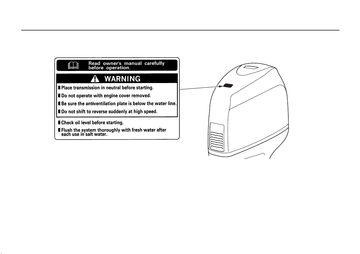
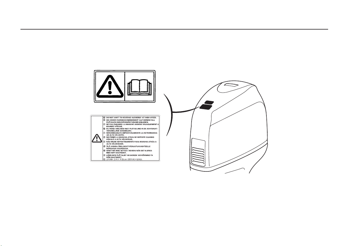
SAFETY LABEL LOCATION
US, Puerto Rico, and US Virgin Islands Types
OUTBOARD MOTOR SAFETY
The label shown here contains important safety information. Please read it carefully. This label is considered a
permanent part of your outboard motor. If the label comes off or becomes hard to read, contact an authorized Honda
Marine dealer for a replacement.
9
OUTBOARD MOTOR SAFETY
Canadian Types
READ OWNER’S MANUAL
The label shown here contains important safety information. Please read it carefully. This label is considered a
permanent part of your outboard motor. If the label comes off or becomes hard to read, contact an authorized Honda
Marine dealer for a replacement.
10
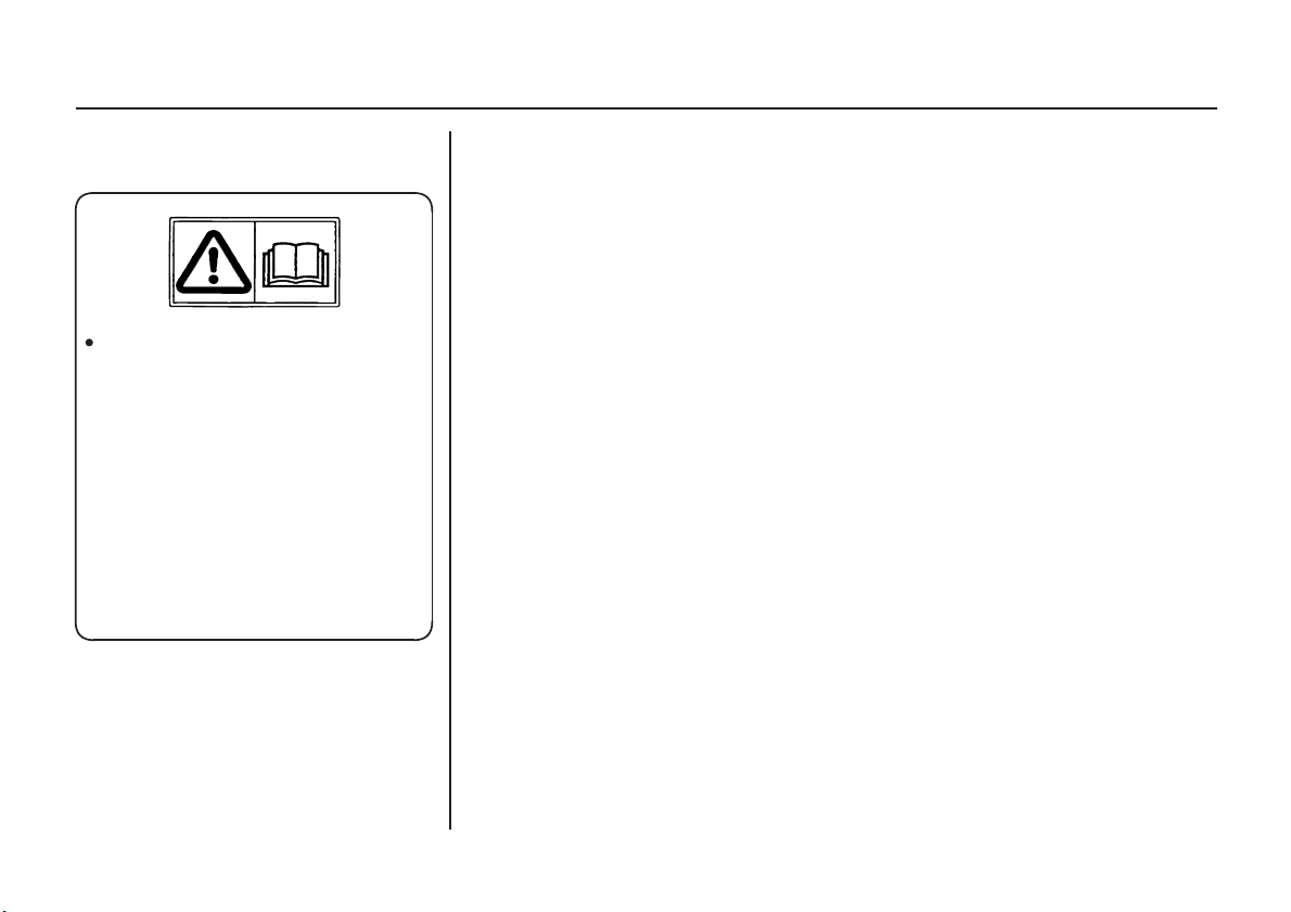
Canadian Types
Honda outboard motor is
designed to give safe and
dependable service if
operated according to
instructions.
Read and understand the
Owner’s Manual before
operating the outboard
motor. Failure to do so
could result in personal
injury or equipment
damage.
OUTBOARD MOTOR SAFETY
11
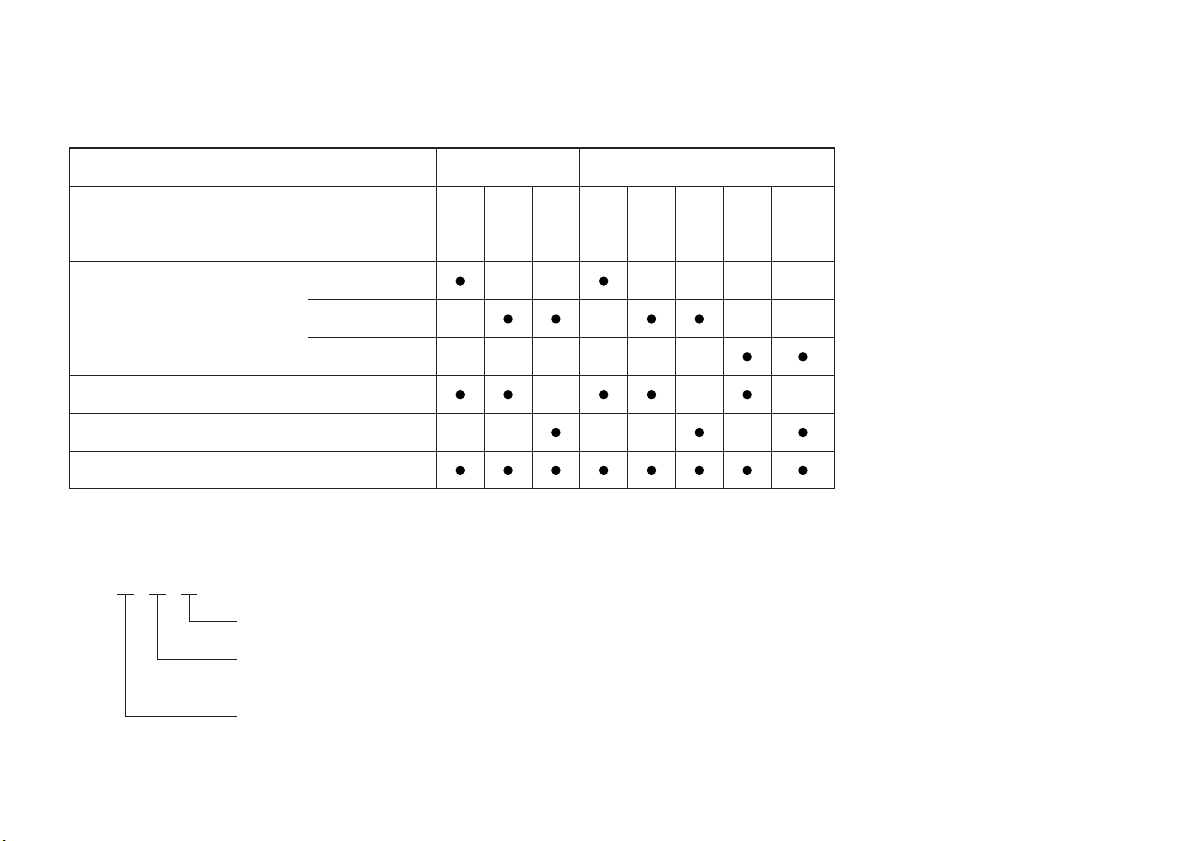
CONTROLS AND FEATURES
CONTROL AND FEATURE IDENTIFICATION CODES
Model
Type
Transom Height
Standard Rotating Propeller Shaft
Counterrotating Propeller Shaft
Power Trim/Tilt
20.0 in (508 mm)
25.0 in (635 mm)
30.0 in (762 mm)
BF200A
LA XA XCA
BF225A
XAXCXCA
XCC
XXA
XXC
XXCALA
Refer to this chart for an explanation of the Type Codes used in this manual to identify control and feature applications.
TYPE CODE (example)
X
AC
Destination
A: American, C: Canadian
Rotating direction of propeller shaft
C: Counterrotating propeller shaft
None: Standard rotating propeller shaft
Transom Height
L: 20.0 in (508 mm), X: 25.0 in (635 mm), XX: 30.0 in (762 mm)
12
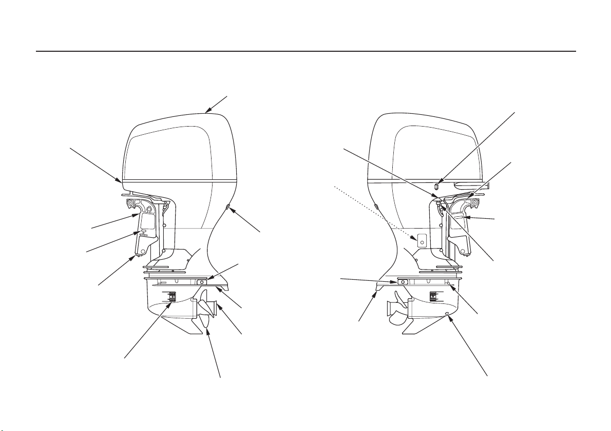
COMPONENT AND CONTROL LOCATIONS
CONTROLS AND FEATURES
ENGINE COVER
LATCH
STERN
BRACKET
MANUAL
RELIEF
VALVE
ANODE
COOLING WATER INTAKE PORT
(each side)
ENGINE COVER
ANODE
PROPELLER
COOLING SYSTEM
INDICATOR
ENGINE OIL
DRAIN BOLT
(inside cover)
IDLE PORT
ANODE
ANTIVENTILATION
PLATE
TRIM TAB
EXHAUST PORT/
WATER OUTLET PORT
POWER TILT
SWITCH
TILT LOCK
LEVER
PRODUCT
IDENTIFICATION
NUMBER
FLUSH PORT
CONNECTOR
GEAR OIL
LEVEL SCREW
GEAR OIL DRAIN/FILL SCREW
13
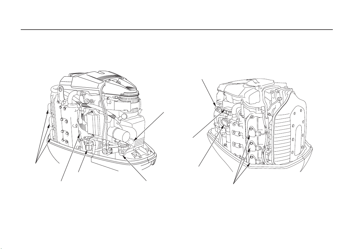
CONTROLS AND FEATURES
OIL FILLER CAP
NMEA INTERFACE
COUPLER
(inside electric parts cover)
ACG FUSE
SPARK PLUGS
(under coil)
OIL LEVEL DIPSTICK
14
WATER SEPARATOR
MAIN FUSE BLOCK
FUEL FILTER
(inside strainer cup)
SPARK PLUGS
(under coil)
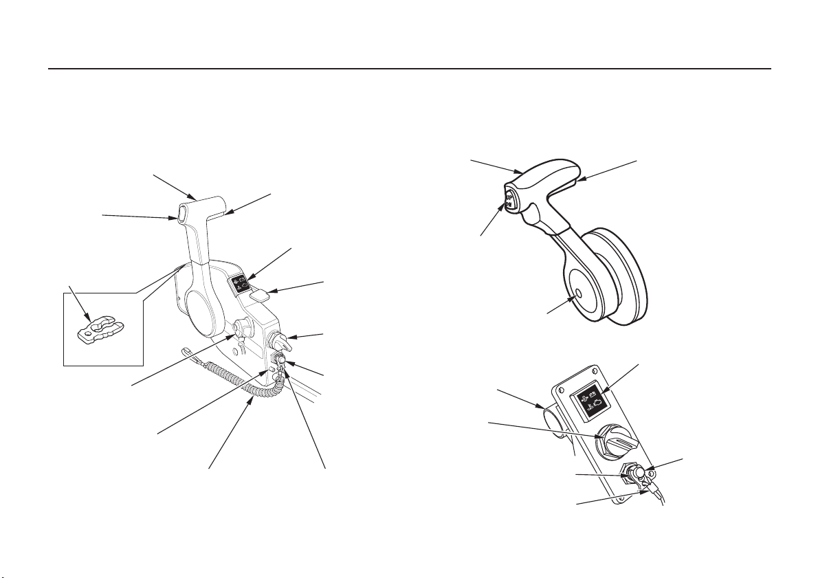
CONTROLS AND FEATURES
Remote Controls (optional equipment)
(SIDE-MOUNT REMOTE CONTROL) (PANEL-MOUNT REMOTE CONTROL)
GEARSHIFT/THROTTLE
GEARSHIFT/THROTTLE
CONTROL LEVER
POWER TRIM/TILT
SWITCH
SPARE SWITCH
CLIP
BUZZER
(inside)
CONTROL LEVER
FRICTION ADJUSTER
EMERGENCY STOP
SWITCH LANYARD
NEUTRAL RELEASE
LEVER
INDICATORS
(Oil pressure, Overheat,
Alternator, Malfunction)
FAST IDLE
LEVER
IGNITION
SWITCH
EMERGENCY
STOP SWITCH
EMERGENCY STOP
SWITCH CLIP
CONTROL LEVER
POWER TRIM/TILT
SWITCH
FAST IDLE BUTTON
CONTROL PANEL
(for PANEL-MOUNT type)
BUZZER
IGNITION
SWITCH
EMERGENCY STOP
SWITCH CLIP
EMERGENCY STOP
SWITCH LANYARD
NEUTRAL RELEASE
LEVER
INDICATORS
(Oil pressure, Overheat,
Alternator, Malfunction)
EMERGENCY
STOP SWITCH
15
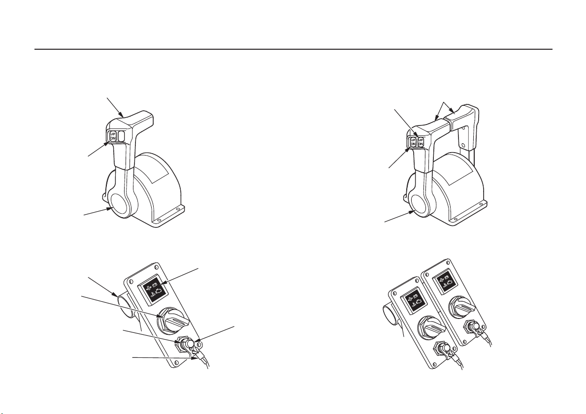
CONTROLS AND FEATURES
(SINGLE TOP-MOUNT REMOTE CONTROL) (DUAL TOP-MOUNT REMOTE CONTROL)
GEARSHIFT/THROTTLE
CONTROL LEVER
POWER
TRIM/TILT
SWITCH
FAST IDLE
BUTTON
CONTROL PANEL
(for TOP-MOUNT SINGLE type)
BUZZER
IGNITION
SWITCH
EMERGENCY STOP
SWITCH CLIP
EMERGENCY STOP
SWITCH LANYARD
GEARSHIFT/THROTTLE
CONTROL LEVERS
POWER TRIM/TILT
SWITCH (RIGHT)
POWER TRIM/TILT
SWITCH (LEFT)
FAST IDLE
BUTTON
(for TOP-MOUNT DUAL type)
INDICATORS
(Oil pressure, Overheat,
Alternator, Malfunction)
EMERGENCY
STOP SWITCH
16
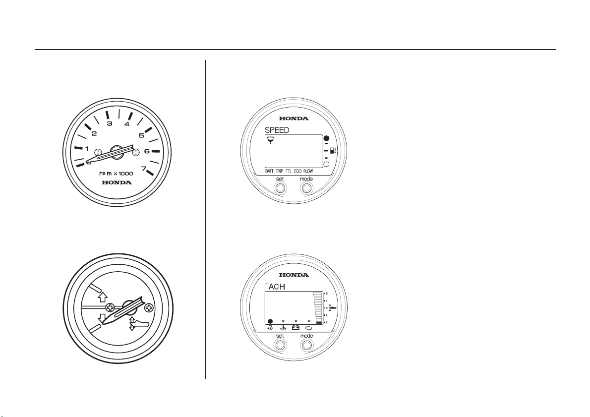
CONTROLS AND FEATURES
Tachometer (optional equipment)
Trim Meter (optional equipment)
Digital Speedometer (optional equipment)
Digital Tachometer (optional equipment)
17
CONTROLS AND FEATURES
CONTROLS
Side-Mount Type
Ignition Switch
OONN
OOFFFF
The ignition switch controls the
ignition system and the starter motor.
START
IGNITION
SWITCH
Turning the ignition switch key to the
START position starts the engine.
The key automatically returns to the
ON position when released from the
START position.
The engine will not start unless the
gearshift/throttle control lever is in
the N (neutral) position (p. ) and
41
the emergency stop switch clip is in
the emergency stop switch.
Turning the ignition switch to the
OFF position stops the engine.
18
CONTROLS AND FEATURES
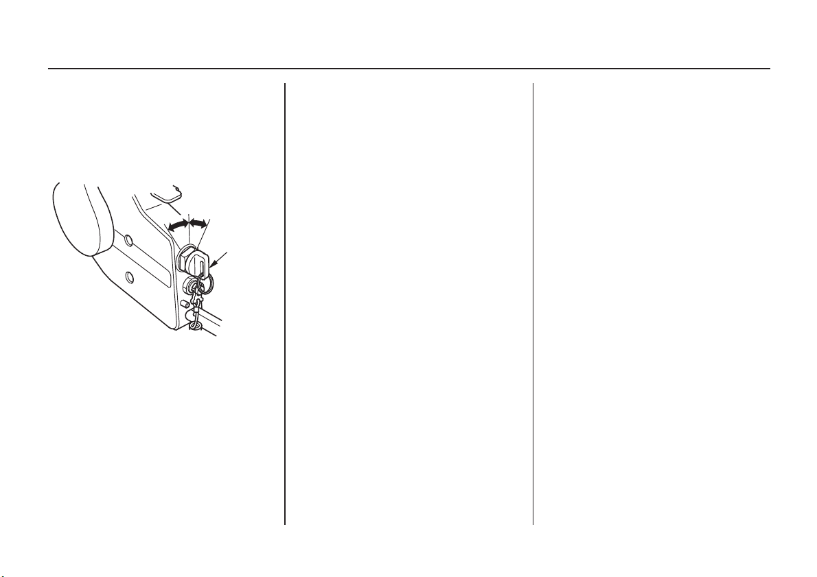
Emergency Stop Switch Clip and Emergency Stop Switch
EMERGENCY
STOP SWITCH
EMERGENCY STOP
SWITCH CLIP
EMERGENCY
STOP SWITCH
CLIP
EMERGENCY
STOP SWITCH
LANYARD
EMERGENCY
STOP SWITCH
LANYARD
The emergency stop switch clip must
be inserted in the emergency stop
switch in order for the engine to start
and run. The emergency stop switch
lanyard must be attached securely to
the operator or to the operator’s PFD
(Personal Flotation Device).
When used as described, the
emergency stop switch clip and
emergency stop switch lanyard
system stops the engine if the
operator falls away from the controls.
A spare switch clip is stored in a slot
in the control housing (optional
equipment).
SPARE SWITCH CLIP
Gearshift/Throttle Control Lever
GEARSHIFT/THROTTLE
CONTROL LEVER
NEUTRAL RELEASE
LEVER
The gearshift/throttle control lever
controls engine speed and selects F
(forward), N (neutral), or R (reverse)
gears.
19
CONTROLS AND FEATURES
Moving the control lever 30° from N
(neutral) selects the gear, and further
movement increases engine speed.
The control lever automatically locks
itself in the N (neutral) position. To
move the lever out of the N (neutral)
position, you must squeeze the
neutral release lever on the underside
of the lever handle.
A friction adjuster near the base of
the control lever(s) adjusts the
operating resistance of the control
lever(s). Refer to p. .52
Less friction allows easier control
lever movement. More friction helps
to hold a steady throttle setting while
cruising.
F (FORWARD)
TTHHRROOTTTTLLEE OOPPEENNIINNGG
MAXIMUM
N (NEUTRAL)
30°
SHIFT
MMIINNIIMMUUMM
GEARSHIFT/THROTTLE
CONTROL LEVER
30°
SHIFT
MMIINNIIMMUUMM
R (REVERSE)
TTHHRROOTTTTLLEE OOPPEENNIINNGG
MAXIMUM
20
CONTROLS AND FEATURES
Fast Idle Lever
FAST IDLE LEVER
Use the fast idle lever to accelerate
engine warm-up after starting the
engine. Do not use the fast idle lever
when starting the engine.
See page for engine warm-up
instructions.
43
N (neutral)
MAXIMUM
FAST IDLE
LOWEST
POSITION
FAST IDLE LEVER
The fast idle lever allows you to
increase the idle speed only when the
control lever is in the N (neutral)
position. Place the fast idle lever in
its lowest position to cancel the fast
idle and return the control lever to
normal operation.
Panel-Mount Type
Ignition Switch
ON
OFF
IGNITION
SWITCH
The ignition switch controls the
ignition system and the starter motor.
START
21
CONTROLS AND FEATURES
Turning the ignition switch key to the
START position starts the engine.
The key automatically returns to the
ON position when released from the
START position.
The engine will not start unless the
gearshift/throttle control lever is in
the N (neutral) position (p. ) and
44
the emergency stop switch clip is in
the emergency stop switch.
Turning the ignition switch to the
OFF position stops the engine.
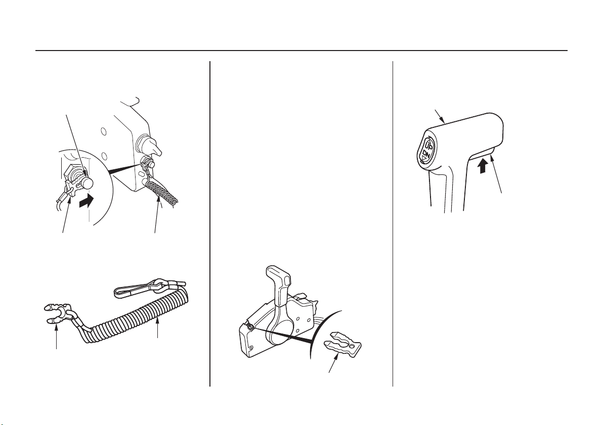
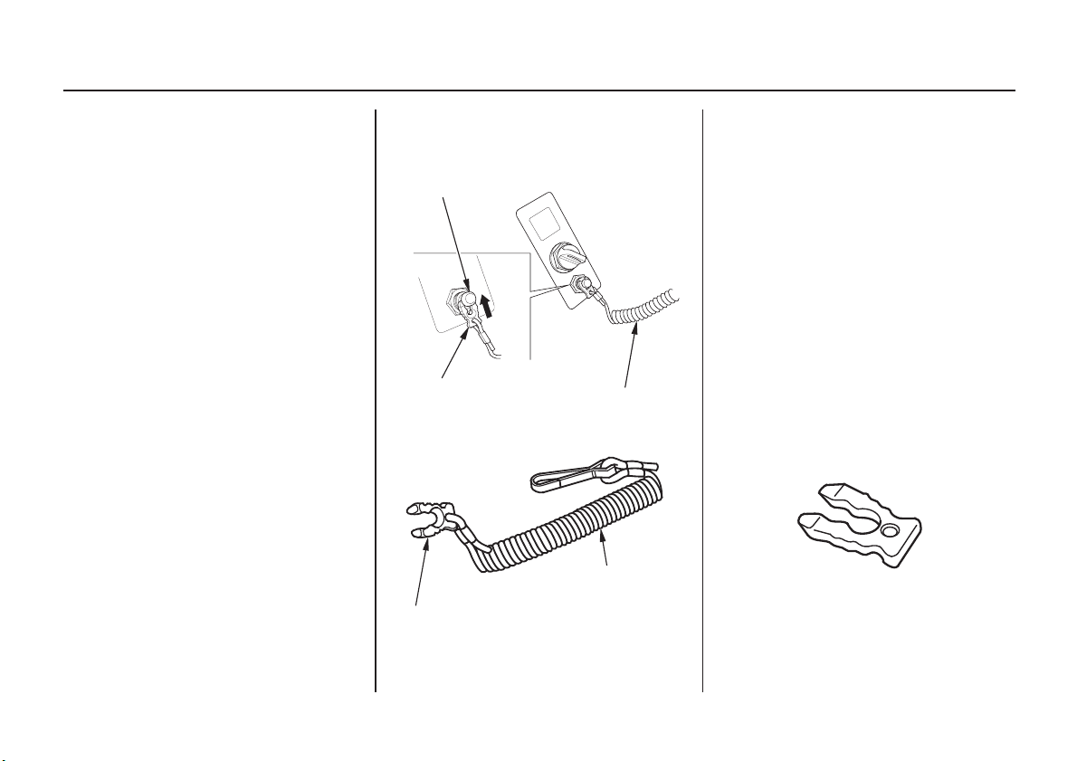
Emergency Stop Switch Clip and Emergency Stop Switch
EMERGENCY
STOP SWITCH
EMERGENCY STOP
SWITCH CLIP
EMERGENCY STOP
SWITCH CLIP
EMERGENCY
STOP SWITCH
LANYARD
EMERGENCY
STOP SWITCH
LANYARD
The emergency stop switch clip must
be inserted in the emergency stop
switch in order for the engine to start
and run. The emergency stop switch
lanyard must be attached securely to
the operator or to the operator’s PFD
(Personal Flotation Device).
When used as described, the
emergency stop switch clip and
emergency stop switch lanyard
system stops the engine if the
operator falls away from the controls.
A spare switch clip (optional
equipment) can be stored in the tool
bag.
SPARE SWITCH CLIP
(optional equipment)
22
CONTROLS AND FEATURES
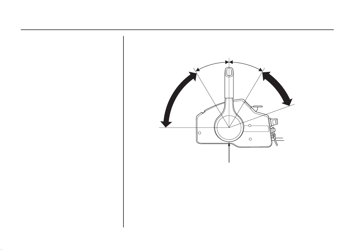
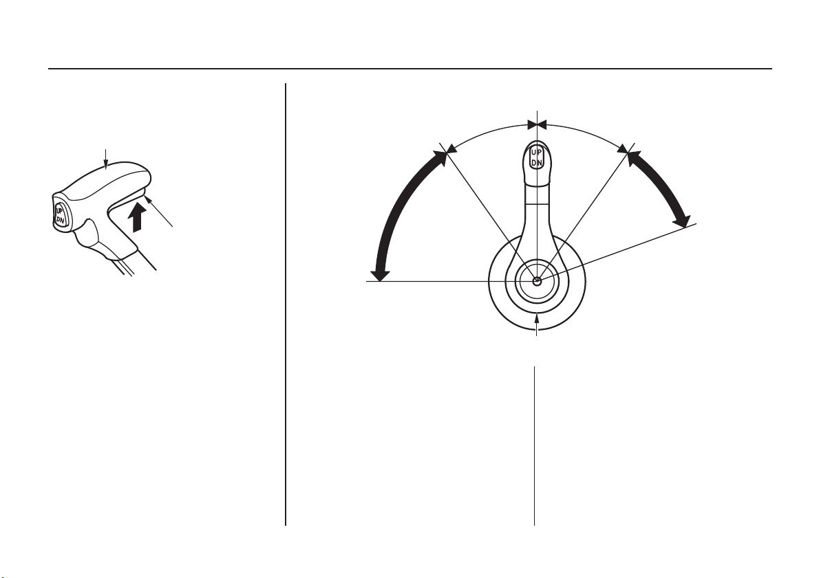
Gearshift/Throttle Control Lever
GEARSHIFT/THROTTLE
CONTROL LEVER
NEUTRAL RELEASE
LEVER
The gearshift/throttle control lever
controls engine speed and selects F
(forward), N (neutral), or R (reverse)
gears.
N (NEUTRAL)
35° 35°
F (FORWARD)
MMIINNIIMMUUMM
TTHHRROOTTTTLLEE OOPPEENNIINNGG
MAXIMUM
GEARSHIFT/THROTTLE
CONTROL LEVER
Moving the control lever 35° from N
(neutral) selects the gear, and further
movement increases engine speed.
The control lever automatically locks
itself in the N (neutral) position. To
move the lever out of the N (neutral)
position, you must squeeze the
neutral release lever on the underside
of the lever handle.
R (REVERSE)
SHIFTSHIFT
MMIINNIIMMUUMM
TTHHRROOTTTTLLEE OOPPEENNIINNGG
MAXIMUM
A friction adjuster near the base of
the control lever adjusts the operating
resistance of the control lever. Refer
to p. .
52
Less friction allows easier control
lever movement. More friction helps
to hold a steady throttle setting while
cruising.
23
CONTROLS AND FEATURES
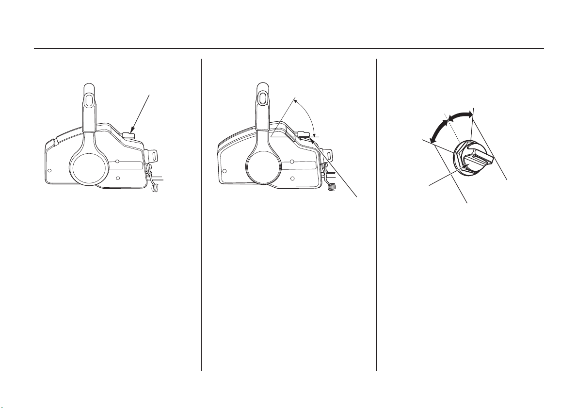
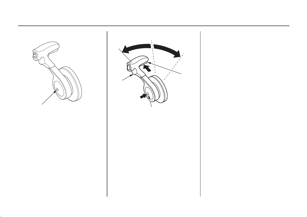
Fast Idle Button
FAST IDLE BUTTON
Use the fast idle button to accelerate
engine warm-up after starting the
engine. Do not use the fast idle
button when starting the engine.
See page for engine warm-up
instructions.
45
F(forward)
CONTROL
LEVER
N(neutral)
PPuullll uupp
Push
FAST IDLE BUTTON
R (reverse)
NEUTRAL
RELEASE
LEVER
The fast idle button allows you to
increase the idle speed without
engaging the drive gears. Move the
control lever forward or reverse after
pushing in the fast idle button to
increase the idle speed.
It is necessary to position the control
lever in the N (neutral) position to
push in the fast idle button.
Return the control lever to N
(neutral) position to cancel the fast
idle operation.
24
CONTROLS AND FEATURES
Top-Mount Type
Ignition Switch
ON
OFF
IGNITION
SWITCH
The ignition switch controls the
ignition system and the starter motor.
Turning the ignition switch key to the
START position starts the engine.
The key automatically returns to the
ON position when released from the
START position.
The engine will not start unless the
gearshift/throttle control lever is in
the N (neutral) position (p. ) and
the emergency stop switch clip is in
the emergency stop switch.
Turning the ignition switch to the
OFF position stops the engine.
START
47
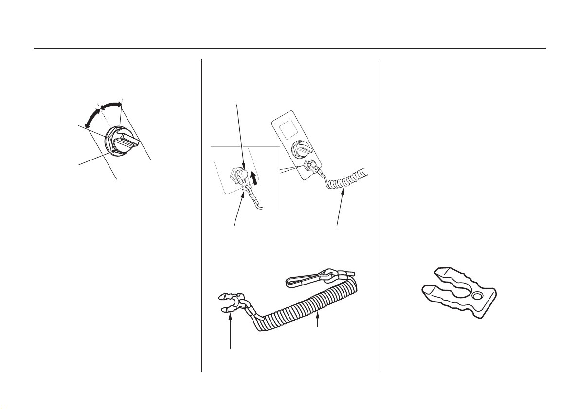
Emergency Stop Switch Clip and Emergency Stop Switch
EMERGENCY STOP SWITCH
EMERGENCY STOP
SWITCH CLIP
EMERGENCY STOP
SWITCH CLIP
EMERGENCY
STOP SWITCH
LANYARD
EMERGENCY
STOP SWITCH
LANYARD
The emergency stop switch clip must
be inserted in the emergency stop
switch in order for the engine to start
and run. The emergency stop switch
lanyard must be attached securely to
the operator or to the operator’s PFD
(Personal Flotation Device).
When used as described, the
emergency stop switch clip and
emergency stop switch lanyard
system stops the engine if the
operator falls away from the controls.
A spare switch clip (optional
equipment) can be stored in the tool
bag.
SPARE SWITCH CLIP
(optional equipment)
25
CONTROLS AND FEATURES
Gearshift/Throttle Control Lever
SINGLE TYPE
GEARSHIFT/
THROTTLE
CONTROL
LEVER
DUAL TYPE
GEARSHIFT/THROTTLE
CONTROL LEVERS
The gearshift/throttle control lever(s)
controls engine speed and selects F
(forward), N (neutral), or R (reverse)
gears.
N (NEUTRAL)
F (FORWARD)
TTHHRROOTTTTLLEE OOPPEENNIINNGG
MAXIMUM
35°
MMIINNIIMMUUMM
GEARSHIFT/THROTTLE
CONTROL LEVER
Moving the control lever 35° from N
(neutral) selects the gear, and further
movement increases engine speed.
A friction adjuster inside the control
box adjusts the operating resistance
of the control lever(s). Refer to
p. .
52
35°
R (REVERSE)
SHIFTSHIFT
TTHHRROOTTTTLLEE OOPPEENNIINNGG
MMIINNIIMMUUMM
MAXIMUM
Less friction allows easier control
lever movement. More friction helps
to hold a steady throttle setting while
cruising.
26
CONTROLS AND FEATURES
Fast Idle Button
FAST IDLE BUTTON
Use the fast idle button to accelerate
engine warm-up after starting the
engine. Do not use the fast idle
button when starting the engine.
See page for engine warm-up
instructions.
48
F(forward)
Push
FAST IDLE BUTTON
N(neutral)
R (reverse)
CONTROL
LEVER
The fast idle button allows you to
increase the idle speed without
engaging the drive gears. Move the
control lever forward or reverse after
pushing in the fast idle button to
increase the idle speed.
It is necessary to position the control
lever in the N (neutral) position to
push in the fast idle button.
Return the control lever to N
(neutral) position to cancel the fast
idle operation.
27
CONTROLS AND FEATURES
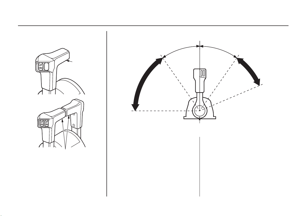
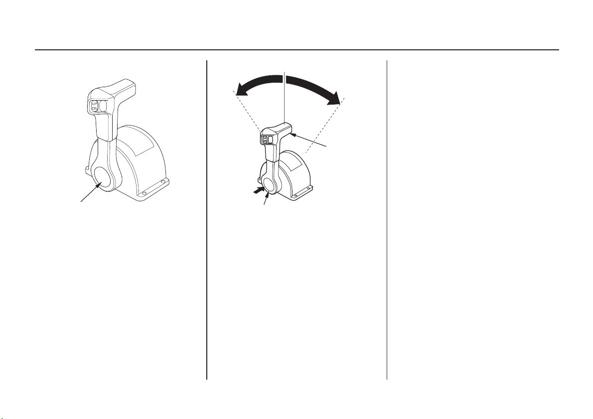
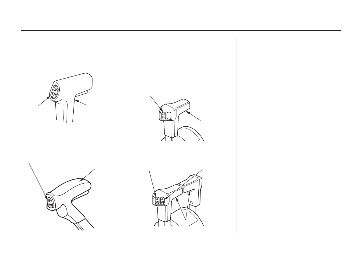
Common Controls
Power Trim/Tilt Switch
(side-mount type) (top-mount type)
SINGLE TYPE
POWER TRIM/TILT SWITCH
CONTROL
POWER
TRIM/TILT
SWITCH
(panel-mount type)
POWER TRIM/TILT SWITCH
LEVER
CONTROL LEVER
DUAL TYPE
POWER TRIM/TILT SWITCH
(LEFT) (RIGHT)
CONTROL
LEVER
The power trim/tilt switch is located
on the control lever. It is a rocker
switch with UP and DN (down)
positions for changing the angle of
the outboard motor.
You can use the power trim/tilt
switch anytime whether the boat is
underway, stopped, or the ignition
switch is in the OFF position. It is
necessary for the ignition switch to
be in the ON position for the trim
meter to indicate the outboard motor
angle.
Trim the outboard motor to obtain
the best performance and stability
(p. ).
53
Tilt the outboard motor for shallow
water operation, beaching, launching,
or mooring.
For dual mount outboard motors, tilt
them up at the same time.
28
CCOONNTTRROOLL
LLEEVVEERRSS
 Loading...