

Page 1

https://truckmanualshub.com/
MENU
FOREWORD
This workshop manual has been prepared to provide information regarding repair procedures on Hino Trucks.
Applicable for J05E engine
When making any repairs on your vehicle, be careful not to be injured through improper procedures.
As for maintenance items, refer to the Owner’s Manual.
All information and specifications in this manual are based upon the latest product information available at the time of printing.
Hino Motors Sales U.S.A. , Inc. reserves the right to make changes at any time without prior notice.
Page 2

https://truckmanualshub.com/
CHAPTER REFERENCES REGARDING THIS WORKSHOP MANUAL
Use this chart to the appropriate chapter numbers for servicing your particular truck.
CHAPTER
MANUAL NO.
MODEL J05E
GENERAL INTRODUCTION 1-001
STANDARD VALUE 2-001
REQUIRED ITEMS 3-001
MOUNTING AND DISMOUNTING THE ENGINE 5-001
ENGINE CONTROL 6-001
FUEL SYSTEM 7-001
EMISSION CONTROL 8-001
S5-LJ05E04A (U.S.A.), S5-LJ05E05A (CANADA)
INTAKE 9-001
ENGINE MECHANICAL 10-001
EXHAUST 11-001
COOLING 12-001
LUBRICATION 13-001
STARTING/CHARGING 16-001
TURBOCHARGER 17-001
Page 3

https://truckmanualshub.com/
INDEX: ENGINE GROUP 1/2
GENERAL INTRODUCTION
STANDARD VALUE
REQUIRED ITEMS
WORKSHOP
MANUAL
TROUBLESHOOTING
MOUNTING AND DISMOUNTING THE ENGINE
ENGINE CONTROL
FUEL SYSTEM
EMISSION CONTROL
INTAKE
ENGINE MECHANICAL
EXHAUST
All rights reserved. This manual may not be
reproduced or copied in whole in part, without the written consent of Hino Motors, Ltd.
COOLING
LUBRICATION
SPEED CONTROL SYSTEM
IGNITION
STARTING/CHARGING
TURBOCHARGER
AIR COMPRESSOR
Page 4

https://truckmanualshub.com/
INDEX: ENGINE GROUP 2/2
ENGINE PTO
(POWER TAKE-OFF)
Page 5

GENERAL INTRODUCTION 1–1
https://truckmanualshub.com/
GENERAL INTRODUCTION
1
HOW TO IDENTIFY VEHICLE TYPE...........................1-2
VEHICLE MODEL ...................................................1-2
VEHICLE IDENTIFICATION NUMBER (VIN)
STRUCTURE ..........................................................1-3
APPEARANCE OF VEHICLE ......................................1-4
APPEARANCE OF VEHICLE .................................1-4
SAFETY INSTRUCTIONS AND READINESS
TO WORK.....................................................................1-5
WARNING...............................................................1-5
IDENTIFICATION INFORMATION ..........................1-9
SAFETY INSTRUCTIONS FOR WORK................1-12
INTRODUCTION TO WORKSHOP MANUAL.......1-15
TIGHTENING OF BOLTS AND NUTS ..................1-19
HANDLING OF LIQUID GASKET.........................1-29
GLOSSARY................................................................1-30
DEFINITION OF ABBREVIATION
IN THIS MANUAL..................................................1-30
LUBRICANTS ............................................................1-36
RECOMMENDED LUBRICANTS .........................1-36
1-001
Page 6
GENERAL INTRODUCTION1–2
X
Ԙ
J
ԙ
C
Ԛ
7
ԛ
0
Ԝ
0
ԝԞ
L
ԟ
H
Ԡ
K
ԡ
T
Ԣ
Q
ԣ
M
Ԥ
A
ԥ
3
Ԧ
CLASSIFICATION
REPORTED MODEL
Ԙԙ
㧦ENGINE MODEL
Ԛ
C
㧦VEHICLE MODEL
HEAVY DUTY TRACK
ԛ
㧦CAB WIDTH, DRIVE, FRAME FORM, WHEEL BASE
Ԝ
70
71
72
74
CAB WIDTH
DRIVE WHEEL BASE
FRAME ASSEMBLY WIDTH
FRAME
FORM
WIDE 2WD MEDIUMOPEN
WIDE 2WD LONGOPEN
WIDE 2WD SUPER LONGOPEN
WIDE 2WD SUPER LONGOPEN
840 mm {33 in.}
2,900 mm {114 in.}
3,500 mm {138 in.}
3,800 mm {150 in.}
4,400 mm {173 in.}
ԝ
0
㧦TYPE OF SUSPENSION
FRONT RIGID, REAR RIGID
Ԡ
CAB FORM BRAKE TYPE
㧦CAB FORM, BRAKE TYPE
ԟ
㧦STEERING WHEEL POSITION
L
LEFT HAND DRIVE
H
Q
SINGLE CAB VACUUM
CREW CAB VACUUM
C
D
SINGLE CAB HYDRAULIC
CREW CAB HYDRAULIC
K
L
SINGLE CAB VACUUM
SINGLE CAB HYDRAULIC
ԡ
㧦DECK HEIGHT
K
HIGH FLOOR
Ԣ
㧦TRANSMISSION
T
6AT
Ԧ
㧦DECK FORM
3
CHASSIS WITH CAB
Ԥ
㧦ENGINE HORSEPOWER, FUEL
FUEL
HORSEPOWER EXHAUST
VERY HIGH US10
DIESEL OIL
M
ԣ
㧦LOADING CAPACITY, GVW, REAR TIRES
ԥ
㧦DESTINATION
DESTINATION
A
U.S., CANADA
6.58 t {14,500 lbs}
8.14 t {17,950 lbs}
8.85 t {19,500 lbs}
Q
T
REAR DOUBLE
REAR DOUBLE
J05E-UG (HV)
XF
J05E-TP (Diesel)
XJ
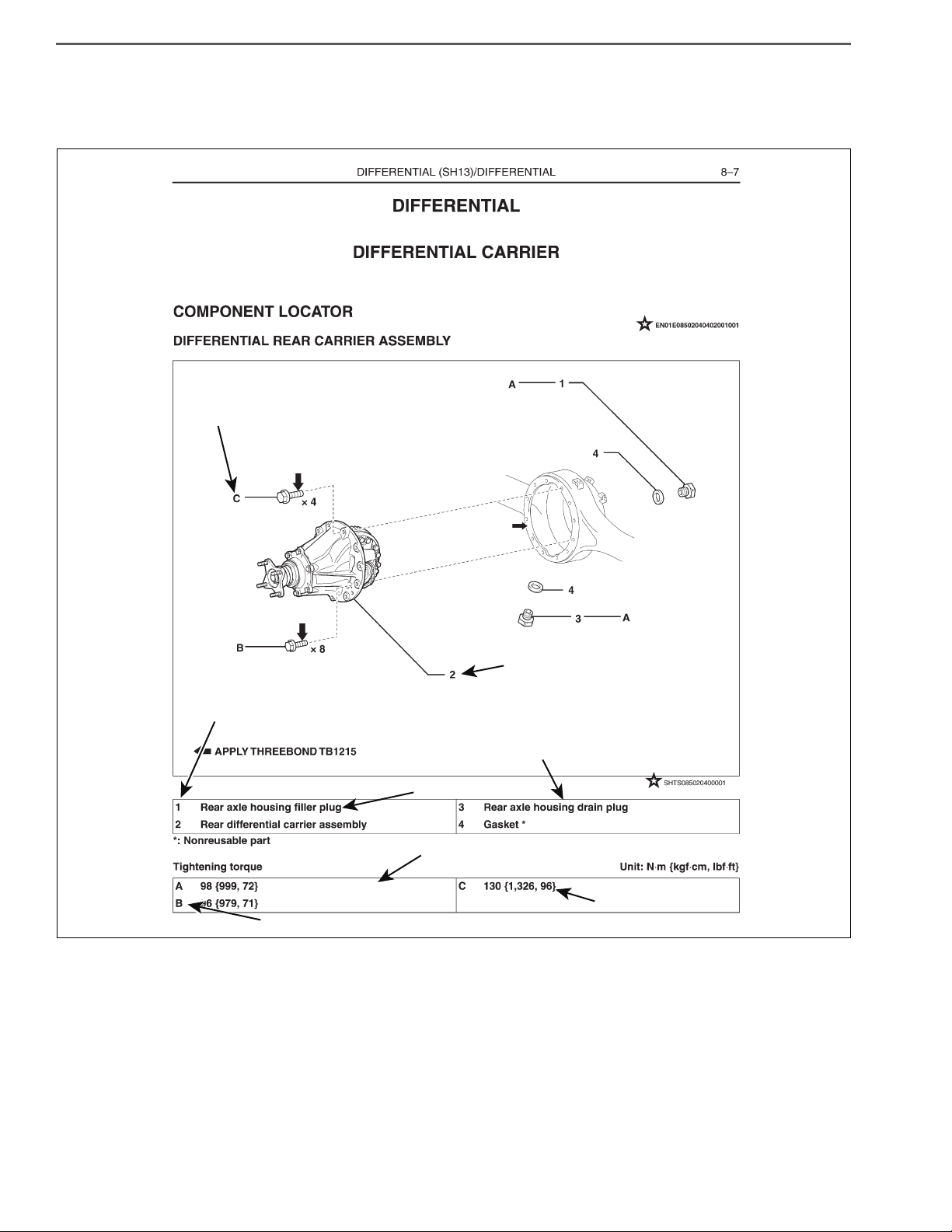
SHTS01ZZZ0000001
https://truckmanualshub.com/
GENERAL INFORMATION
HOW TO IDENTIFY VEHICLE TYPE
VEHICLE MODEL
EN01F01ZZZ000102001001
Page 7

GENERAL INTRODUCTION 1–3
WMI VDS CD VIS
(1) (2) (3) (4) (5) (6) (7) (8) (9)
(10) (11) (12) (13) (14) (15) (16)
JHH KDM2H 5 E K00100
(17)
1
MANUFACTURER ,TYPE
MODEL, CAB TYPE,
WHEEL BASE,
BRAKE SYSTEM
MODEL YEAR
ENGINE MODEL
ASSEMBLY PLANTSERIES
MAKE
CHECK DIGIT
SEQUENTIAL NUMBER
CODE
JHN INCOMPLETE VEHICLE
TYPEMANUFACTURER
HINO MOTORS, LTD.
2AY
INCOMPLETE VEHICLE
HINO MOTORS
CANADA, LTD.
CODE CODE YEARYEAR
H 2017
J 2018
K 2019
L 2020
M 2021
C 2012
D 2013
E 2014
F 2015
G 2016
CODE
PM Hybrid
APPLICATIONENGINE MODEL
J05E
DM DieselJ05E
CODE
1
1
2
ASSEMBLY PLANT
HINO MOTORS, LTD.
HINO PLANT IN JAPAN
HINO MOTORS, LTD.
Hamura Plant in Japan
3 Canada Plant
4
K
W.V Plant
CODE
CODE
H
MAKE
SERIES GVWR
HINO
6,580 kg
{14,500 lbs.}
8,140 - 8,850 kg
{17,950 - 19,500 lbs.}
CODE CLASS MODEL
R
S
T
PRODUCTION
CODE
CAB TYPE WHEEL BASE
BRAKE
SYSTEM
U
V
W
X
Y
P
H
K
L
HINO 195h
HINO 195
HINO 195
HINO 195
HINO 155
HINO 155
HINO 155
HINO 155
HINO 195
HINO 195
HINO 155
HINO 155
5
5
5
5
4
4
5
5
4
4
4
4
XFC710
HINO 155h
XFC720
HINO 155h
XFC740
HINO 195h
XFC720
HINO 195h
XFC740
HINO 155h
XFC710
HINO 195h
XFC720
HINO 195h
XFC740
HINO 155h
XFC740
HINO 155h
XFC720
HINO 195 XJC710
COE
SINGLE CAB
COE
SINGLE CAB
COE
SINGLE CAB
COE
SINGLE CAB
COE
SINGLE CAB
COE
SINGLE CAB
COE
SINGLE CAB
COE
SINGLE CAB
COE
CREW CAB
COE
CREW CAB
COE
CREW CAB
COE
CREW CAB
3500mm{138 in.}
3500mm{138 in.}
2900mm{114 in.}
2900mm{114 in.}
3800mm{150 in.}
3800mm{150 in.}
3800mm{150 in.}
3800mm{150 in.}
4400mm{173 in.}
4400mm{173 in.}
4400mm{173 in.}
4400mm{173 in.}
XJC700
XJC700
XJC710
XJC720
XJC740
XJC740
XJC720
XJC720
XJC740
XJC720
XJC740
HYDRAULIC
HYDRAULIC
HYDRAULIC
HYDRAULIC
HYDRAULIC
HYDRAULIC
VACUUM
VACUUM
VACUUM
VACUUM
VACUUM
VACUUM
SHTS01ZZZ0000002
https://truckmanualshub.com/
VEHICLE IDENTIFICATION NUMBER (VIN) STRUCTURE
EN01F01ZZZ000102001002
Page 8
GENERAL INTRODUCTION1–4
SHTS01ZZZ0000003
https://truckmanualshub.com/
APPEARANCE OF VEHICLE
APPEARANCE OF VEHICLE
EN01F01ZZZ000102002001
Page 9

GENERAL INTRODUCTION 1–5
https://truckmanualshub.com/
SAFETY INSTRUCTIONS AND READINESS TO WORK
WARNING
EN01F01ZZZ000102003001
GENERAL PRECAUTIONS
Some recommended and standard maintenance services for your vehicle are included in this section. When performing
maintenance on your vehicle be careful not to get injured by improper work. Improper or incomplete work can cause a malfunction of the vehicle which may result in personal injury and/or property damage. If you have any question about performing maintenance, please consult your Hino dealer.
WARNING
When working on your vehicle, observe the following general precautions to prevent death, personal injury and/
or property damage in addition to the particular DANGERS, WARNINGS, CAUTIONS and NOTICES in each chapter.
• Always wear safety glasses or goggles to protect your eyes.
• Remove rings, watches, ties, loose hanging jewelry and loose clothing before starting work on the vehicle.
• Bind long hair securely behind the head.
• When working on the vehicle, apply the parking brake firmly, place the gear shift lever in "Neutral" or "N"
and block the wheels.
• Always turn off the starter switch to stop the engine, unless the operation requires the engine running.
Removing the key from the switch is recommended.
• To avoid serious burns, keep yourself away from hot metal parts such as the engine, exhaust manifold,
radiator, muffler, exhaust pipe and tail pipe.
• Do not smoke while working on the vehicle since fuel, and gas from battery are flammable.
• Take utmost care when working on the battery. It contains corrosive sulfuric acid.
• Large electric current flows through the battery cable and starter cable. Be careful not to cause a short
which can result in personal injury and/or property damage.
• Read carefully and observe the instructions specified on the jack before using it.
• Use safety stands to support the vehicle whenever you need to work under it. It is dangerous to work under
a vehicle supported only by a jack.
• If it is necessary to run the engine after the hood is raised (tilted), make sure that the parking brake is
firmly applied, the wheels are blocked, and the gear shift lever is positioned in "Neutral" before staring the
engine.
• Run the engine only in a well-ventilated area to avoid inhalation of carbon monoxide.
• Keep yourself, your clothing and your tools away from moving parts such as the cooling fan and V-belts
when the engine is running.
• Be careful not to damage lines and hoses by stepping or holding your feet on them.
• Be careful not to leave any tool in the engine compartment. The tool may be hit by moving parts, which can
cause personal injury.
Page 10
GENERAL INTRODUCTION1–6
! WARNING
B
F
E
G
SHTS01ZZZ0000004
https://truckmanualshub.com/
PRECAUTIONS IN TILTING AND LOWERING THE CAB
Be sure to observe the following when tilting and lowering the cab to reduce the risk of an accident which may
result in death, serious injury and/or property damage.
• Park the vehicle on a level place and ensure ample space around the cab before tilting the cab.
• Apply the parking brake firmly and place the gearshift lever in “N” position (“P” position if your vehicle is
equipped with automatic transmission).
• Stop the engine and block the wheels.
• Remove any articles in or over the cab and close the doors firmly.
• Make sure there is no one in or around the cab and there are no obstacles in front of the vehicle or above the
cab.
• The catch (E), stopper (F), stay (G) and other parts such as the engine, radiator, and exhaust pipe can be very
hot while your vehicle is operated. Be sure to confirm they have been cooled down before you start working
under the cab.
• Never raise or lower the cab only by yourself if your cab is equipped with heavy component such as a roof
rack.
• Never put your body under the cab while raising or lowering the cab.
• Make sure the cab stopper stay is securely locked by the catch (E) and raise the stopper (F) to lock the catch
(E) completely after raising the cab.
• Before lowering the cab, make sure that any object such as hand tools, gloves or cloth are not left under the
cab.
• Make sure the handle (B) is caught by the catch after lowering the cab.
Read the Owner’s manual for details.
DEFINITION OF SAFETY TERMS
Indicates an extremely hazardous situation if proper procedures are not followed and
could result in death or serious injury.
Indicates a potential hazardous situation if proper procedures are not followed and
could result in death or serious injury.
Indicates a hazardous situation if proper procedures are not followed and could result
in serious injury or damage to parts/equipment.
Indicates the need to follow proper procedures and to pay attention to precautions so
that efficient service is provided.
Provides additional information to help you to perform the repair efficiently.
Page 11

GENERAL INTRODUCTION 1–7
https://truckmanualshub.com/
TOWING
• When being towed, always place the gear shift lever in "Neutral" and release the parking brake completely. In order to
protect the bumper, fit a protection bar against the lower edge of the bumper and put a wood block under the frame
near the No. 1 cross member when attaching the towing chain. Never lift or tow the vehicle if the chain is in direct contact with the bumper.
1. Towing procedures
(1) Make sure that the propeller shaft of the vehicle to be towed is removed. When the differential gear or rear axle shaft
is defective, remove both right and left rear axle shafts, then cover the hub opening to prevent loss of axle lubricant
and entry of dirt or foreign matter.
(2) Use a heavy duty cable or rope when towing the vehicle. Fasten the cable securely to the towing hook on the frame.
(3) The angle of pulling direction of the cable fastened to the towing hook must not exceed 15° in horizontal and vertical
directions from the straight ahead, level direction. Avoid using the hook in a way that subjects it to jerk, as in towing a
vehicle trapped in a gutter.
(4) Keep the gear shift lever in Neutral.
(5) Make sure that the starter switch is kept in the "ON" position, if the engine is not running.
(6) Make sure that the engine of the towed vehicle is kept running. If the engine is off, no compressed air/ no vacuum will
be available for the brake. This is dangerous, as the brake system does not function if the engine is not running.
In addition, the power steering system will not function. The steering wheel, therefore, will become unusually hard to
turn, making it impossible to control the vehicle.
(7) Note that the engine brake and exhaust brake cannot be applied, if the propeller shaft is removed.
(8) Make a slow start to minimize shock. Towing speed should be less than 30 km/h {18 mile/h}.
2. If the engine of the towed vehicle is defective, make sure that the vehicle is towed only by a tow truck
designed for that purpose.
(1) Front end towing (with front wheels raised off the ground)
When towing from the front end with the front wheels raised off the ground, remove the rear axle shafts to protect the
transmission and differential gears from being damaged. The hub openings should be covered to prevent the loss of
axle lubricant or the entry of dirt or foreign matter. The above-mentioned precautions should be observed for vehicles
equipped with either manual or automatic transmission, and for even short distance towing. After being towed, check
and refill the rear axle housing with lubricant if necessary.
(2) Rear end towing
When being towed with the rear wheels raised off the ground, fasten and secure the steering wheel in a straight-
ahead position.
CLEAN AIR ACT
1. Heavy-duty engine rebuilding practices.
§ 86.004-40
• The provisions of this section are applicable to heavy-duty engines subject to model year 2004 or later standards and
are applicable to the process of engine rebuilding (or rebuilding a portion of an engine or engine system). The pro-
cess of engine rebuilding generally includes disassembly, replacement of multiple parts due to wear, and reassembly,
and also may include the removal of the engine from the vehicle and other acts associated with rebuilding an engine.
Any deviation from the provisions contained in this section is a prohibited act under section 203(a) (3) of the Clean Air
Act (42 U.S.C. 7522(a) (3)).
(1) When rebuilding an engine, portions of an engine, or an engine system, there must be a reasonable technical basis
for knowing that the resultant engine is equivalent, from an emissions standpoint, to a certified configuration (i.e., tol-
erances, calibrations, specifications) and the model year(s) of the resulting engine configuration must be identified. A
reasonable basis would exist if:
a. Parts installed, whether the parts are new, used, or rebuilt, are such that a person familiar with the design and
function of motor vehicle engines would reasonably believe that the parts perform the same function with respect
to emissions control as the original parts; and
b. Any parameter adjustment or design element change is made only:
• In accordance with the original engine manufacturer's instructions; or
• Where data or other reasonable technical basis exists that such parameter adjustment or design element change,
when performed on the engine or similar engines, is not expected to adversely affect in-use emissions.
(2) When an engine is being rebuilt and remains installed or is reinstalled in the same vehicle, it must be rebuilt to a con-
figuration of the same or later model year as the original engine. When an engine is being replaced, the replacement
engine must be an engine of (or rebuilt to) a configuration of the same or later model year as the original engine.
Page 12

GENERAL INTRODUCTION1–8
https://truckmanualshub.com/
(3) At time of rebuild, emissions-related codes or signals from on-board monitoring systems may not be erased or reset
without diagnosing and responding appropriately to the diagnostic codes, regardless of whether the systems are
installed to satisfy requirements in § 86.004-25 or for other reasons and regardless of form or interface. Diagnostic
systems must be free of all such codes when the rebuilt engine is returned to service. Such signals may not be rendered inoperative during the rebuilding process.
(4) When conducting a rebuild without removing the engine from the vehicle, or during the installation of a rebuilt engine,
all critical emissions-related components listed in § 86.004-25(2) not otherwise addressed by paragraphs (1) through
(3) of this section must be checked and cleaned, adjusted, repaired, or replaced as necessary, following manufacturer recommended practices.
(5) Records shall be kept by parties conducting activities included in paragraphs (1) through (4) of this section. The
records shall include at minimum the mileage and/or hours at time of rebuild, a listing of work performed on the
engine and emissions-related control components including a listing of parts and components used, engine parameter adjustments, emissions-related codes or signals responded to and reset, and work performed under paragraph
(4) of this section.
a. Parties may keep records in whatever format or system they choose as long as the records are understandable
to an EPA enforcement officer or can be otherwise provided to an EPA enforcement officer in an understandable
format when requested.
b. Parties are not required to keep records of information that is not reasonably available through normal business
practices including information on activities not conducted by themselves or information that they cannot reasonably access.
c. Parties may keep records of their rebuilding practices for an engine family rather than on each individual engine
rebuilt in cases where those rebuild practices are followed routinely.
d. Records must be kept for a minimum of two years after the engine is rebuilt.
2. Maintenance instructions.
§ 86.010-38
(1) For each new diesel-fueled engine subject to the standards prescribed in § 86.007-11, as applicable, the manufac-
turer shall furnish or cause to be furnished to the ultimate purchaser a statement that
"This engine must be operated only with ultra low-sulfur diesel fuel (meeting EPA specifications for highway
diesel fuel, including a 15 ppm sulfur cap)."
Page 13
GENERAL INTRODUCTION 1–9
A
B
SHTS01ZZZ0000010
https://truckmanualshub.com/
IDENTIFICATION INFORMATION
EN01F01ZZZ000102003002
1. VEHICLE IDENTIFICATION NUMBER
(1) The vehicle identification number (VIN) is stamped on the right
frame, as shown in the illustration. This number has also been
stamped on the manufacture's label.
A: Vehicle Identification Number (VIN)
B: Manufacturer's Label
(2) VIN
See VEHICLE IDENTIFICATION NUMBER (VIN) STRUCTURE
on the following page.
(3) PRODUCTION CODE AND VEHICLE COMPONENTS
MODEL (CLASS) HINO 155h (4) HINO 155 (4) HINO 195h (5) HINO 195 (5)
XJC700
XJC710
XJC720
XJC740
PRODUCTION CODE
XFC710
XFC720
XFC740
TRANSMISSION SERIES A465
1st 3.742
2nd 2.003
3rd 1.343
TRANSMISSION RATIO
4th 1.000
5th 0.773
6th 0.634
REAR AXLE SERIES SH13
REAR AXLE RATIO 4.333 / 4.625 / 4.875 / 5.142 / 5.571 / 5.857
SERVICE BRAKE Vacuum Hydraulic
PARKING BRAKE ACTING ON DIFFERENTIAL OUTPUT SHAFT
SUSPENSION LEAF
XFC710
XFC720
XFC740
XJC700
XJC710
XJC720
XJC740
Page 14
GENERAL INTRODUCTION1–10
FOR ALL MODELS
SHTS01ZZZ0000011
A
SHTS01ZZZ0000012
A
SHTS01ZZZ0000013
SHTS01ZZZ0000014
https://truckmanualshub.com/
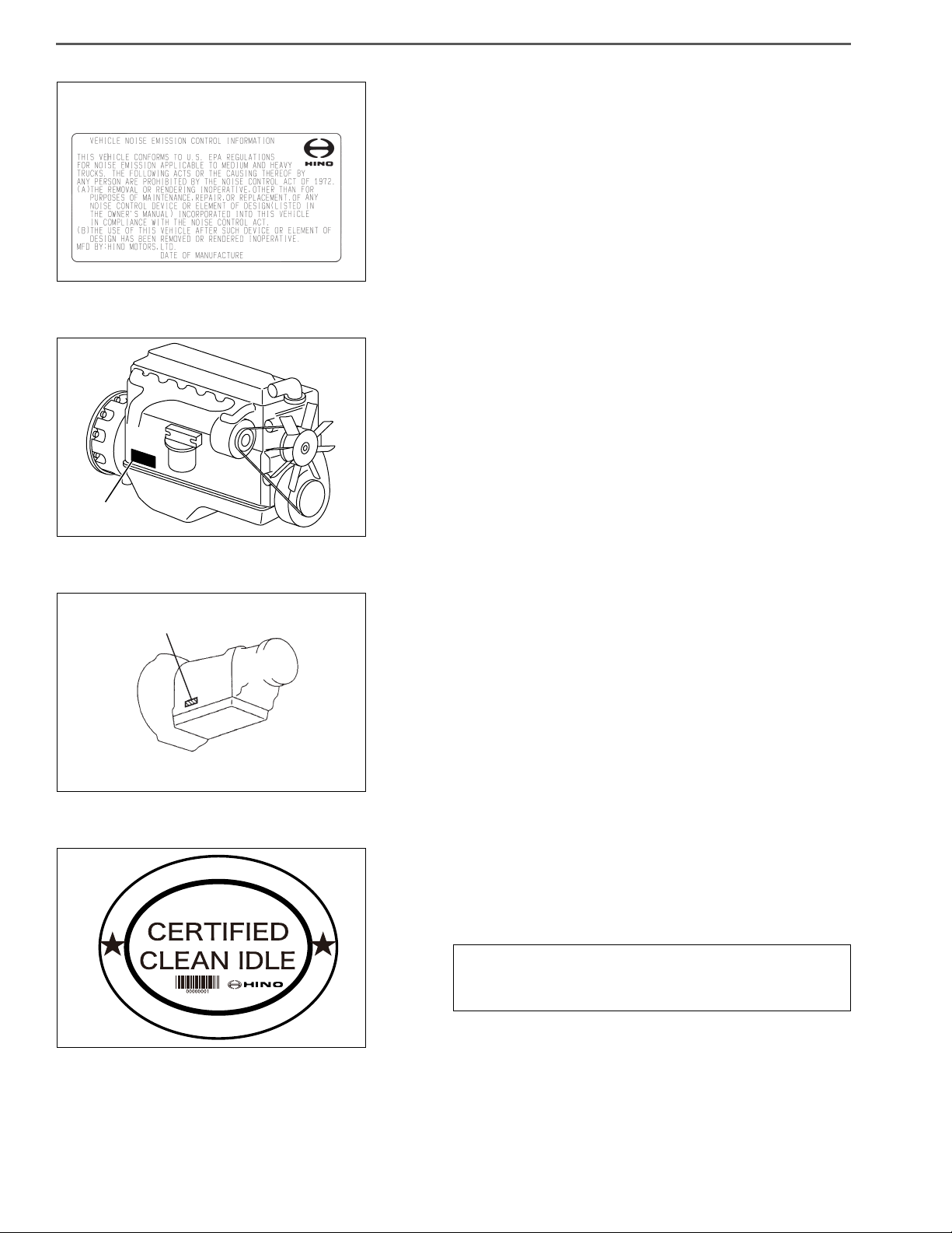
2. VEHICLE NOISE EMISSION CONTROL INFORMATION
• The Vehicle Noise Emission Control Information is affixed to the
left pillar of the cab. The name of manufacturer, production year
and month, and noise emission applicable to medium and heavy
trucks in conformity with U.S. EPA Regulations are displayed.
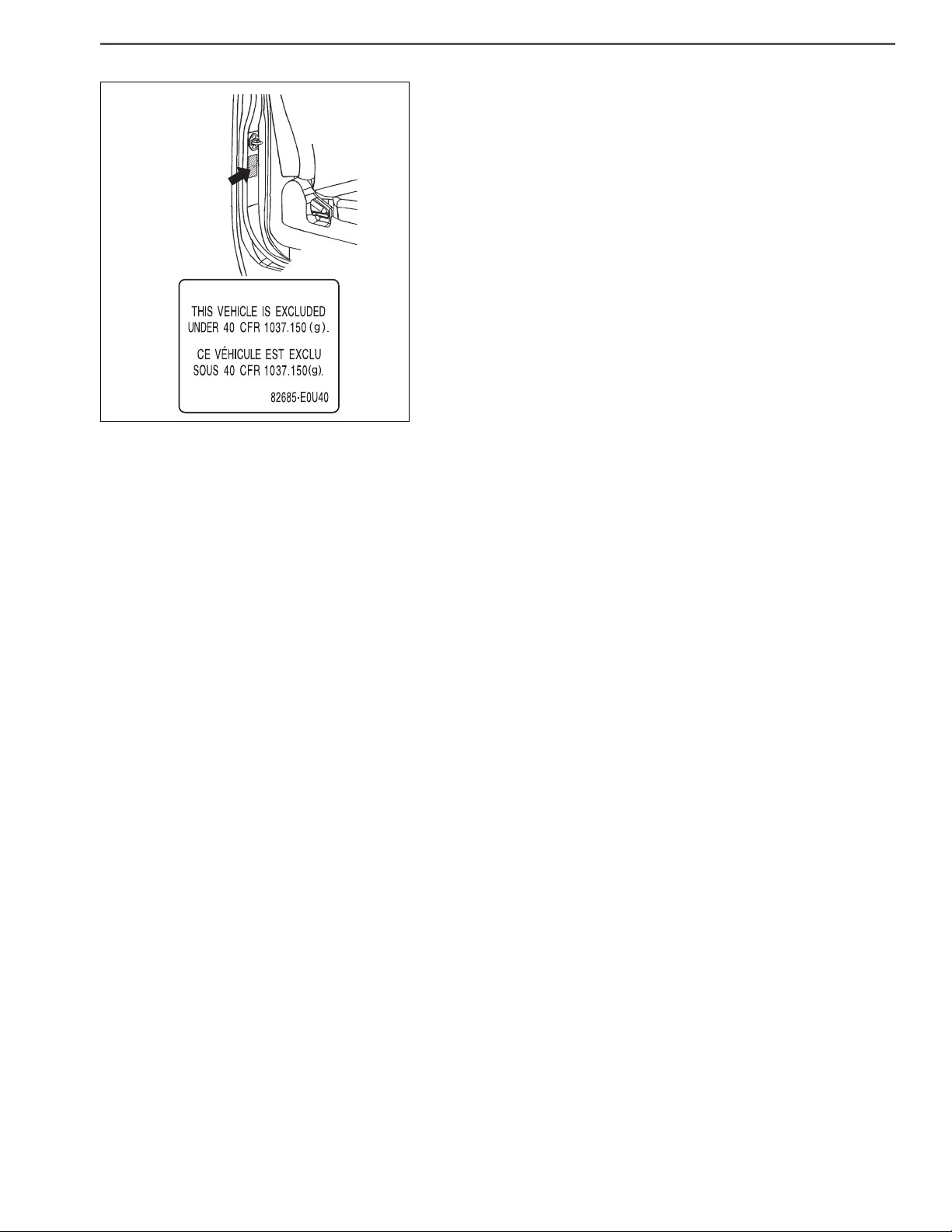
3. ENGINE SERIAL NUMBER
(1) The engine serial number is stamped on the cylinder block, as
shown in the illustration.
A: J05E
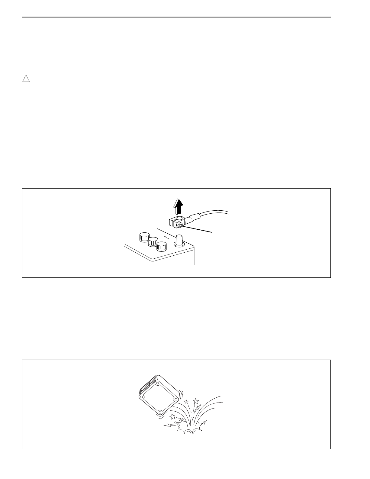
4. TRANSMISSION SERIAL NUMBER
(1) The transmission serial number is stamped on the transmission,
as shown in the illustration.
A: A465
5. CLEAN IDLE CERTIFIED LABEL FOR U.S.
• Make sure that the following clean engine idling certified label is
affixed to the outside of the left door. By the CARB below, the
label must be affixed there to prove that the new vehicle with diesel engine manufactured from Jan., 2008 conforms to this low.
CARB § 1956.8. Exhaust Emission Standard and Test
Procedure (a) (b) Heavy-Duty Diesel Engine Idling
Requirements
Page 15
GENERAL INTRODUCTION 1–11
EXEMPTION LABEL
SHTS01ZZZ0000015
https://truckmanualshub.com/
6. EXEMPTION LABEL FOR US GHG REGULATION
HINT
Exemption label fuel economy comes in paste right side of the
front passenger seat.
However, this label is limited to one year.
Page 16
GENERAL INTRODUCTION1–12
! WARNING
SHTS01ZZZ0000016
LOOSEN
SHTS01ZZZ0000017
https://truckmanualshub.com/
SAFETY INSTRUCTIONS FOR WORK
EN01F01ZZZ000102003003
PRECAUTIONS
1. SAFETY INSTRUCTIONS FOR HANDLING ELECTRICAL SYSTEMS
(1) Remove the battery cable
• Be sure to wait for at least ten minutes after the starter key is turned to "LOCK" position before you discon-
nect the battery terminals from the battery, as the vehicle data is recorded on ECU and DCU starts working
for the exhaust gas after treatment after the starter key is turned to "LOCK" position. Otherwise, the vehicle
data will not be recorded on ECU properly and DCU will not complete working properly, which may result in
the malfunction of DPR system and DEF-SCR system.
• The MIL (malfunction indicator light) may come on when the starter key is turned to "ON" position again,
even if you wait for at least ten minutes before disconnecting the battery terminals from the battery after the
starter key is turned to "LOCK" position. In this case, use HINO-DX to clear the DTC (P204F and P068A), to
turn off the MIL and to conduct DPR regeneration manually.
a. Before electrical system work, remove the cable from the minus terminal of the battery in order to avoid burning
caused by short-circuiting.
b. To remove the battery cable, fully release the nut to avoid damage to the battery terminal. Never twist the termi-
nal.
(2) Handling of electronic parts
a. Never give an impact to electronic parts of a computer or relay.
b. Keep electronic parts away from high temperatures and humidity.
c. Never splash water onto electronic parts in washing the vehicle.
d. Do not remove the harness connector, electric component box, and cover except for repair and inspection.
If removal is necessary, pay attention that water and foreign matters do not attach or enter to the connector, terminals, electric component box, and cover.
In restoration, make sure there is no attachment or entry of water and foreign matters and mount them properly,
because it causes degradation of waterproof function.
INCORRECT
Page 17
GENERAL INTRODUCTION 1–13
SHTS01ZZZ0000018
INCORRECT
INCORRECT
CORRECT
SHTS01ZZZ0000019
https://truckmanualshub.com/
(3) Handling of wire harness
a. Perform marking on a clamp and a clip and secure then in original position so that the wire harness will not inter-
fere with the end and acute angle section of the body and a bolt.
b. To attach a part, take care not to bite the wire harness.
INCORRECT
INCORRECT
INCORRECT
(4) Handling of connectors
a. When removing a connector, hold a connector (area shown in an arrow in the figure) and then pull it off. Do not
pull wire harnesses.
b. Pull off a lockable connector after unlocking.
c. When connecting a lockable connector, make sure to insert a lockable connector until it makes a click sound.
d. When inserting a test lead, insert it from the back of a connector.
e. If it is difficult to insert a test lead from the back of a connector, make and use an inspection harness.
Page 18

GENERAL INTRODUCTION1–14
! WARNING
! WARNING
SHTS01ZZZ0000020
Connect the ground of the ARC welding
machine near the place on the frame to be
welded but not connect it to plated parts such
as fuel pipes, brake pipes and leaf spring.
Disconnect the ground terminal for
battery at the connecting point on the
frame and disconnect the ground for
computer as well.
CHASSIS FRAME
CHASSIS FRAME
BATTERY
ALTERNATOR
ETC.
COMPUTER
ARC WELDING
MACHINE
https://truckmanualshub.com/
(5) Installation of battery disconnect switch
• Installation of the battery disconnect switch on the power supply circuit for the dosing control unit of DEF-
SCR (DCU) may damage or result in the malfunction of DEF-SCR system.
• Be sure to read and follow the procedures and instructions on the service bulletin before the installation of
the battery disconnect switch.
(6) Handling of battery disconnect switch
• Wait for at least ten minute before using the battery disconnect switch after the starter key is turned to
"LOCK" position.
Otherwise, the vehicle data will not be recorded on ECU properly, which may result in the malfunction of DPR
system.
2. PRECAUTION FOR ELECTRIC WELDING
Electrical components such as the alternator and tachograph are directly connected to the battery and one
end is earthed to the chassis frame. Under these conditions, welding current will flow back along the earth
circuit if electric welding is carried out and damage may be caused to the alternator, tachograph, electrical
components, etc. Consequently, the following precautions are always to be taken during welding.
(1) Disconnect the earth terminal of the battery at the frame fitment and earth the welding equipment securely to the
frame itself. (Do not fit the welding equipment earth to such things as the tire rims, brake pipes or fuel pipes and leaf
spring, etc.)
a. Turn the starter switch off.
b. Disconnect the battery’s negative terminal of the battery.
c. Earth welding equipment securely, near to the area to be welded.
d. Put back battery negative ground as original condition.
e. Finally check the functioning of all instruments.
(2) In order to prevent damage to ancillary equipment components from sparks during welding, take steps such as put-
ting fire-resistant covers over things like the engine, meters, steering wheel, hoses, leaf spring and tires.
Page 19

GENERAL INTRODUCTION 1–15
https://truckmanualshub.com/
INTRODUCTION TO WORKSHOP MANUAL
EN01F01ZZZ000102003004
GENERAL
1. SCOPE OF REPAIR DESCRIPTIONS
(1) There are three major processes in repair work: i.e. "troubleshooting," "removal/installation, replacement, overhaul,
assembly, inspection and adjustment" and "final inspection".
(2) This document covers only the first process (troubleshooting) and the second process (removal/installation, replace-
ment, overhaul, assembly, inspection and adjustment) and omits the third process (final inspection).
(3) The element tasks listed below are omitted from this document but must be done in actual repair work.
a. Jacking and lifting
b. Cleaning and washing of removed parts as required
c. Visual check
2. STANDARD VALUE
(1) Standard values, limits, required actions and tightening torques are tabulated in this document.
3. REQUIRED ITEMS
(1) Special tools, tools, instruments, oil and grease and other items to be prepared before starting work are listed in the
section titled "REQUIRED ITEMS". Note that general tools, jacks, rigid racks and other required items supposedly
available at a general service shop are omitted from the list.
4. REPRESENTATION OF SECTION AND TITLE
(1) Under a title containing a system name such as "ENGINE CONTROL SYSTEM", the descriptions cover "INSPEC-
TION", "ADJUSTMENT", "REPLACEMENT" and "OVERHAUL" of components.
(2) Under a title containing a part name such as "AIR COMPRESSOR ASSEMBLY", the descriptions cover "REPLACE-
MENT" and "OVERHAUL".
Page 20
GENERAL INTRODUCTION1–16
Alphabetical mark indicating the
tightening torque in the following
tightening torque table
Numerical order indicating the
part name in the following part
name table
Numerical order
Part name
Part name table
Tightening torque table
Tightening torque
Alphabetical mark
SHTS01ZZZ0000021
INTRODUCTION TO DESCRIPTIONS
1. COMPONENT LOCATOR
https://truckmanualshub.com/
☆ : The ID number is given to required items for the purpose of preparing electronic data and is not needed
in repair work.
Page 21
2. WORK STEPS
Indicating the work
sequence
Descriptive text: Indicating the work
method which is gone into detail
Indicating the part number of
SST required for work
SHTS01ZZZ0000022
GENERAL INTRODUCTION 1–17
https://truckmanualshub.com/
Page 22

GENERAL INTRODUCTION1–18
https://truckmanualshub.com/
DEFINITION OF TERM
Terms used in this document are defined as follows.
DIRECTION
1. CHASSIS RELATED
(1) Longitudinal direction
a. The forward direction and the reverse direction of a vehicle are respectively defined as front and rear in the
installed position in a vehicle.
(2) Rotational direction
a. The clockwise direction and the counterclockwise direction viewed from the rear side of a vehicle are defined as
right-handed and left-handed respectively.
(3) Vertical direction
a. The upward direction and the downward direction in the installed position in a vehicle are defined as an upper
side and a lower side respectively.
(4) Lateral direction
a. The leftward direction and the rightward direction viewed from the back of a vehicle are respectively defined as a
left side and a right side in the installed position in a vehicle.
2. INDIVIDUAL DEVICES
(1) Longitudinal direction
a. The input side and the output side of motive power are defined as a front side and a rear side respectively.
(2) Rotational direction
a. The clockwise direction and the counterclockwise direction viewed from the back side are defined as right-
handed and left-handed respectively.
(3) Vertical direction
a. The upward direction and the downward direction of a device in its installed position in a vehicle (chassis) are
defined as an upper side and a lower side respectively.
(4) Lateral direction
a. The leftward direction and the rightward direction as viewed from the back side are defined as a left side and a
right side respectively.
STANDARD VALUE
Represents a basic dimension (excluding a tolerance), and a clearance arising from tolerances when two parts are assembled.
REPAIR LIMIT
Represents a numerical value indicating need of correction. A symbol "+" or "-" indicated next to a repair limit represents
an increase or a decrease from a standard value.
SERVICE LIMIT
Represents a numerical value indicating need of replacement. A symbol "+" or "-" indicated next to a repair limit represents
an increase or a decrease from a standard value.
Page 23

GENERAL INTRODUCTION 1–19
https://truckmanualshub.com/
TIGHTENING OF BOLTS AND NUTS
EN01F01ZZZ000102003005
BOLTS AND NUTS
More than hundreds of bolts/nuts are used in a vehicle and improper handling of them will cause damage and looseness.
Because tightening torque varies depending on tightening condition, strength class, and surface treatment, etc., make sure
to check the types and tightening torques of bolts/nuts and use them properly.
PURPOSES OF TIGHTENING TORQUE
Predefined tightening torque must be applied to ensure sufficient tightening by threads.
It also has purposes to prevent the adverse events below due to excessive or insufficient tightening.
Conditions Adverse events
• Stretch or fracture of bolt
• Depression of seat surface and looseness
Excessive tightening
Insufficient tightening
• Gasket damage
• Rounding and damage of hexagon part
• Opening of spring washer
• Looseness
• Gas and liquid Leakages
• Continuity failure
• Damage by fretting wear
NOTICE
Unique tightening torque may be specified for some parts.
Tighten with the tightening torque specified in the service manual.
HINT
Check the tightening torque list for general torques.
CAUTIONS TO PREVENT LOOSENESS.
When tightening, pay attention to the followings to prevent looseness after tightening.
• Insufficient tightening torque
• Inclusion of foreign matters (burrs and coatings) in the tightening surface.
• Sagging of coat
• Sinking into the seat surface hole by omitting attaching a plain washer.
• Defective seat surface flatness (wear-out during use)
Page 24
GENERAL INTRODUCTION1–20
SHTS01ZZZ0000023
SHTS01ZZZ0000024
FLANGE OUTER DIAMETER
GROOVES
GROOVES
SHTS01ZZZ0000025
FLANGE OUTER DIAMETER
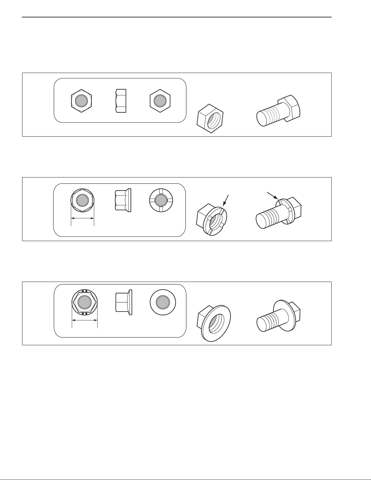
TYPES AND IDENTIFICATION
There are three types of bolts and nuts.
1. Standard (w/o flange)
• Bolts/nuts without flange
2. With old flange (w/grooves)
• Flange is small and has grooves on its back.
https://truckmanualshub.com/
3. With new flange (w/o grooves)
• Flange is big and does not have grooves on its back.
Page 25
SHTS01ZZZ0000026
SEAT SURFACE WITH OLD FLANGE
SEAT SURFACE WITH NEW FLANGE
NO COMPATIBILITY
BOLTS/NUTS WITH OLD FLANGE (W/GOOVES)
BOLTS/NUTS WITH NEW FLANGE (W/O GOOVES)
SEAT SURFACE WITH OLD FLANGE
SEAT SURFACE WITH NEW FLANGE
https://truckmanualshub.com/
Comparison of flange outer diameters
Bolt Nut
GENERAL INTRODUCTION 1–21
Thread
diameter
With old flange
(w/grooves)
Strength
class
Flange
outer
diameter
With new flange
(w/o grooves)
Strength
class
Flange
outer
diameter
With old flange
(w/grooves)
Strength
class
Flange
outer
diameter
With new flange
(w/o grooves)
Strength
class
M8 7T, 9T 15.5 8.8, 10.9 17 7N 15.5 8 17
8.8 20
M10 7T, 9T 18.5
7N 18.5 8 21.5
10.9 21.5
8.8 24
M12 7T, 9T 21.5
7N 21.5 8 26
10.9 26
M14 ——10.9 30.5 ——12 30
COMPATIBILITY (NO COMPATIBILITY IN BOLTS AND NUTS)
Flange
outer
diameter
NOTICE
[Bolt/nuts with new flange (w/o grooves)] can not be used on the place where [bolts/nuts with old flange (w/
grooves)] were used. In addition, use care to avoid misassembly because even when nominal sizes and pitches
are same, there is no compatibility in strength if types are different.
Page 26

GENERAL INTRODUCTION1–22
https://truckmanualshub.com/
STRENGTH CLASSES AND SYMBOLS
1. With old flange (w/grooves)
Bolt Nut
Strength
class
4T —
9T
2. With new flange (w/o grooves)
Strength
class
Carbon steel Boron steel
Carbon steel Boron steel
Symbols
Bolt Nut
Symbols
Strength
class
7N7T
Strength
class
Symbols
Symbols
8.8 8
10.9 12
Page 27

PAR T N O.
1. Standard (w/o flange)
GENERAL INTRODUCTION 1–23
https://truckmanualshub.com/
Thread
diameter
M8
M10
M12
M14 9T SH112-**** Plating 8N SL113-01411 Plating
2. With old flange (w/grooves)
Thread
diameter
M8
Strength
class
7T SH111-**** Plating
9T SH112-**** Plating
7T SH111-**** Plating
9T SH112-**** Plating
7T SH111-**** Plating
9T SH112-**** Plating
Strength
class
7T SH562-**** Plating
9T SH562-**** Plating
Bolt Nut
Par t No.
Bolt Nut
Par t No.
Surface
treatment
Surface
treatment
Strength
class
8N SL113-00807 Plating
8N SL113-01008 Plating
8N SL113-01210 Plating
Strength
class
7N SL151-00809 Plating
Par t No.
Par t No.
Surface
treatment
Surface
treatment
M10
M12
7T SH562-**** Torquer
7N SL151-01011 Plating
9T SH562-**** Torquer
7T SH562-**** Torquer
7N SL151-01213 Plating
9T SH562-**** Torquer
Page 28

3. With new flange (w/o grooves)
GENERAL INTRODUCTION1–24
https://truckmanualshub.com/
Thread
diameter
M8
M10
M12
M14 10.9 91552-F14** Neotorquer 12 94151-21401 Neotorquer
NOTICE
Some bolts/nuts are applied friction stabilizer on thread surface. Note that their tightening torques are different
from those of plated-only bolts/nuts even if the strength class is same. (Threads with Neotorquer are colored in
light red.)
HINT
The * below the hyphen of a part number shows a thread diameter and length under head, so the numbers vary
depending on type.
Strength
class
8.8 91551-808** Plating
10.9 91551-008** Plating
8.8 91552-E10** Neotorquer
10.9 91552-F10** Neotorquer
8.8 91552-E12** Neotorquer
10.9 91552-F12** Neotorquer
Bolt Nut
Par t No.
Surface
treatment
Strength
class
8 94151-80800 Plating
8 94151-81001 Neotorquer
8 94151-81201 Neotorquer
Par t No.
Surface
treatment
LIST OF TIGHTENING TORQUE
Apply a tightening torque specified in the strength class of the bolt/nut used.
NOTICE
Refer to the service manual because tightening torques of some parts do not conform to it due to their tightening
conditions, strength classes, and surface treatments.
1. Standard (w/o flange)
Unit: Nm {kgfcm, lbfft}
Thread diameter Strength classes Tightening Torque
M8
M10
M12
M14 9T 160.032.0 {1,630326, 117.923.5}
7T 22.04.0 {22445, 16.22.9}
9T 29.05.5 {29656, 23.14.0}
7T 43.08.5 {43886, 31.76.2}
9T 57.011.0 {581112, 42.08.1}
7T 76.015.0 {774152, 56.011.0}
9T 100.020.0 {1,019203, 73.714.7}
Page 29

GENERAL INTRODUCTION 1–25
https://truckmanualshub.com/
2. With old flange (w/grooves)
Thread diameter Strength classes Tightening Torque
Unit: Nm {kgfcm, lbfft}
M8
M10
M12
3. With new flange (w/o grooves)
Thread diameter Strength classes Tightening Torque
M8
M10
M12
7T 22.04.0 {22445, 16.22.9}
9T 29.05.5 {29656, 23.14.0}
7T 51.510.0 {525101, 37.97.3}
9T 68.513.5 {698137, 50.59.9}
7T 91.018.0 {927183, 67.013.2}
9T 120.024.0 {1,223224, 88.417.6}
8.8 31.09.3 {31694, 22.86.8}
10.9 39.011.7 {397119, 28.78.6}
8.8 35.010.5 {356107, 25.87.7}
10.9 46.513.8 {474140, 34.210.1}
8.8 63.018.9 {642
10.9 82.024.6 {836250, 60.418.1}
192, 46.413.9}
Unit: Nm {kgfcm, lbfft}
M14 10.9 130.039.0 {1,325397, 95.828.7} 130.026.0 {1,325265, 95.819.1}*
HINT
*: Value is for usage in the fuel tank.
Page 30

GENERAL INTRODUCTION1–26
https://truckmanualshub.com/
TIGHTENING OF ENGINE BOLTS AND NUTS
1. TIGHTENING TORQUE FOR GENERAL STANDARD BOLTS
(1) Representative tightening torque for shouldered bolts
Unit: Nm {kgfcm, lbfft}
Thread diameter X pitch 7T 9T
M8 X 1.25 (coarse thread) 28.5 {290, 21} 36 {370, 27}
M10 X 1.25 (fine thread) 60 {610, 44} 74.5 {760, 55}
M10 X 1.5 (coarse thread) 55 {560, 40} 68.5 {700, 51}
M12 X 1.25 (fine thread) 108 {1,100, 80} 136 {1,390, 101}
M12 X 1.75 (coarse thread) 97 {990, 72} 125 {1,280, 93}
M14 X 1.5 (fine thread) 171.5 {1,750, 127} 216 {2,210, 160}
M14 X 2 (coarse thread) 154 {1,570, 114} 199 {2,030, 147}
Remark
(2) Representative torque for washer bolt
Thread diameter X pitch 4T 7T 9T
M6 X 1 (coarse thread) 6 {60, 4.3} 10 {100, 7.2} 13 {130, 9.4}
M8 X 1.25 (coarse thread) 14 {140, 10} 25 {250, 18} 31 {320, 23}
M10 X 1.25 (fine thread) 29 {300, 22} 51 {520, 38} 64 {650, 47}
M10 X 1.5 (coarse thread) 26 {270, 20} 47 {480, 35} 59 {600, 43}
M12 X 1.25 (fine thread) 54 {550, 40} 93 {950, 69} 118 {1,200, 87}
M12 X 1.75 (coarse thread) 49 {500, 36} 83 {850, 61} 108 {1,100, 80}
M14 X 1.5 (fine thread) 83 {850, 61} 147 {1,500, 108} 186 {1,900, 137}
M14 X 2 (coarse thread) 74 {750, 54} 132 {1,350, 98} 172 {1,750, 127}
Bolt with a numerical
character "4" indicated on
Remark
the head Projection bolt.
Stud with a rounded free
end.
Bolt with a numerical character "7"
indicated on the head
Bolt with a numerical
character "7" indicated on
the head. Stud with a
chamfered free end.
Bolt with a numerical character "9"
indicated on the head
Unit: Nm {kgfcm, lbfft}
Bolt with a numerical
character "9" indicated on
the head
Page 31

GENERAL INTRODUCTION 1–27
SHTS01ZZZ0000040
SEAL LOCKING AGENT
SHTS01ZZZ0000041
EXAMPLE OF WORK
ONE TURN BY 90
ONE TURN BY 90
ONE TURN BY 45
TIGHTEN
BY 90
TIGHTEN BY 90
(1ST TURN)
TIGHTEN BY 45
(2ND TURN)
TWO TURNS BY 90
TIGHTEN BY 90
(1ST TURN)
TIGHTEN BY 90
(2ND TURN)
https://truckmanualshub.com/
2. PRECOAT BOLT
(1) Reapply locking agent if:
a. a precoat bolt has been removed, or
b. a precoat bolt has been turned during a tightening check or other activities. (loosened or tightened)
HINT
• A precoat bolt is a bolt of which threads are applied with seal locking agent.
• Conduct a torque check with the lower limit of a permissible tightening torque range. If a bolt has been
turned or rotated, follow the procedures below to retighten a bolt.
(2) Steps for reusing precoat bolt lock
a. Clean a bolt and a screw hole. (Also clean a screw hole if replacement is made.)
b. Use air blower to dry out.
c. Apply specified seal locking agent to bolt threads.
3. PLASTIC-REGION TIGHTENING METHOD (TURNING ANGLE CONTROL)
NOTICE
• Some of engine parts employ the plastic-region tightening method.
• Said tightening method is different from the conventional tightening method. Follow the instructions
(1) Applicable parts
NOTICE
Prior to installation, measure a total length of a bolt. If a measurement reading of a total length exceeds the service limit, replace the bolts.
In installation work, apply engine oil to a bolt seat surface and bolt threads.
(2) Tightening after tightening with seating torque
described in this document for tightening.
Cylinder head bolt, crankshaft main bearing cap bolt, connecting rod bearing cap bolt, and etc.
Tighten to the angle specified in this document: i.e. tighten another 90, 135 (90 once and then 45 once) or 180
(90 twice).
Page 32

GENERAL INTRODUCTION1–28
https://truckmanualshub.com/
TIGHTENING OF FLARE NUTS AND HOSES
1. TIGHTENING TORQUE FOR PIPE FLARE NUTS
HINT
Steel pipes and copper pipes (excluding power steering pipe).
Unit: Nm {kgfcm, lbfft}
Outer diameter
of pipe
Tightening
torque
TIGHTENING TORQUE FOR POWER STEERING PIPE FLARE NUTS
Typ es
Feed pipe
(high pressure)
Return pipe
(low pressure)
4.76 6.35 8 10 12 15
Brake:15
{153,11}
Except brake:
150.5
{1535.1,
110.37}
Material quality and
shape
Copper (Outer diame-
ter 10) (Wall thick-
ness t=1.4)
Copper (Outer diame-
ter 10) (Wall thick-
ness t=1)
Clutch:24
{245,18}
Except
clutch:
211
{21410,
150.7}
Flare configuration Identification Tightening torque
323
{32631,
242.2}
Single flare Red 44±5 {44951,323.7}
Single flare — 44±5 {44951,323.7}
445
{44951,
323.7}
645
{65351,
473.7}
Unit: Nm {kgfcm, lbfft}
662.5
{67325,
491.8}
2. TIGHTENING TORQUE FOR HOSES
Unit: Nm {kgfcm, lbfft}
Outer diameter of hose13
fittings
Brake hose — 462.5 {46925,341.8} —
Power steering
oil hose
3. TIGHTENING TORQUE FOR STEEL JOINT LOCK NUTS
Nominal des-
ignation of
thread
Tightening
torque
M14 M16 M20 M22 M24
4810
{489102, 357.3}
——44±5 {44951,323.7}
6613
{673204, 499.5}
Outer diameter of hose13,
20, 22, packing unit fittings
12036
{1,224367,
26.5}
89
{1,346306,
Outer diameter of hose
PF 3/8 fittings
Unit: Nm {kgfcm, lbfft}
13030
9722.1}
15030
{1,530306,
11122.1}
Page 33

GENERAL INTRODUCTION 1–29
SHTS01ZZZ0000042
SPRAY GUN
CARTRIDGE
WINDING TOOL
TUBE
SHTS01ZZZ0000043
21
NOZZLE OF THE TUBE
https://truckmanualshub.com/
HANDLING OF LIQUID GASKET
EN01F01ZZZ000102003006
LIQUID GASKET
1. PROCEDURES FOR APPLYING LIQUID GASKET AND ASSEMBLING PARTS
(1) Thoroughly remove old liquid gasket remaining on individual parts and mating parts. Use clean cloth to remove oil,
moisture, dirt or other contaminants.
Make sure to overlap the start and end points of liquid gasket.
(2) Use care to avoid misalignment with a mating part when assembling a gasket-applied part. If misalignment is found,
reapply liquid gasket.
(3) Install parts within 20 minutes after applying liquid gasket.
If 20 minutes or longer time has elapsed, remove and reapply liquid gasket.
(4) Wait at least 15 minutes after assembling parts and then start the engine.
2. REMOVAL OF PARTS
(1) When removing individual parts, alternately winkle two or more portions in a gap or a collar of a flange. Avoid one-
point winkling. When removing a gasket, use care to avoid entry of gasket fragments into the engine.
3. OTHERS
(1) If liquid gasket is contained in a tube, use a supplied squeezer. If liquid gasket is contained in a cartridge, use a appli-
cator gun.
If liquid gasket is contained in a tube, the nozzle tip can be cut off to the desired application width.
1: Cut off the first block will form a application width of approximately 2 mm {0.079 in.}.
2: Cut off the second block will form a application width of approximately 5 mm {0.197 in.}.
1
Page 34

GENERAL INTRODUCTION1–30
https://truckmanualshub.com/
GENERAL INFORMATION
GLOSSARY
DEFINITION OF ABBREVIATION IN THIS MANUAL
LIST OF ABBREVIATION
Abbreviations Meaning, or Official Name
A/C Air Conditioner
ABS Anti-lock Brake System
ACC Accessory
AMT Automated Manual Transmission
ATC After Turbo Catalyst
ATF Automatic Transmission Fluid
CA Crank Angle
CAN Controller Area Network
CD-ROM Compact Disc Read Only Memory
CPU Central Processing Unit
dB Decibel
DC Direct Current
EN01F01ZZZ000102006001
D-CAT Diesel-Clean Advanced Technology System
DC motor Direct Current Motor
DCU Dosing Control Unit
DEF Diesel Exhaust Fluid
DPR Diesel Particulate active Reduction system
DSS Driving Support System
ECU Electronic Control Unit
EEPROM Electronically Erasable and Programmable Read Only Memory
EGR Exhaust Gas Recirculation
ELR Emergency Locking Retractor
ENG Engine
ES START Easy and Smooth start system
F/A Front Axle
FCCB Fuel Control Cylinder Balance
FCV Fuel Cutoff Valve
FF shift Feather touch & Finger shift
FL Fusible link
Page 35

GENERAL INTRODUCTION 1–31
https://truckmanualshub.com/
Abbreviations Meaning, or Official Name
Fr Front
FRP Fiber Reinforced Plastic
FUP Front Underrun Protector
GCU Glow Control Unit
GND Ground
GVW Gross Vehicle Weight
Hi High
HINO-DX HINO Diagnostic eXplorer
HV Hybrid Vehicle
HVAC Heating, Ventilating and Air-Conditioning unit
I.S.C. Idle Speed Control
IC Integrated Circuits
ID Identification
IPD Intelligent Power Device
IS Idle Stop
ISO International Organization for Standardization
JIS Japanese Industrial Standards
LED Light Emitting Diode
LEV Low Emission Vehicle
LH Left Hand
LLC Long Life Coolant
Lo Low
MAX Maximum
MIN Minimum
MS evaporator Multi-tank and Super slim structure evaporator
MT Manual Transmission
No. Number
NOx Nitrogen Oxide
NMR No load Maximum Revolution
OHC Over Head Camshaft
PC Personal Computer
PCD Pitch Circle Diameter
PCS Pre-Crash Safety
PCV Pump Control Valve
PCV valve Positive Crankcase Ventilation valve
Page 36

GENERAL INTRODUCTION1–32
https://truckmanualshub.com/
Abbreviations Meaning, or Official Name
PM Particulate Matter
PPG Glass-fiber-reinforced Polypropylene
ppm Parts Per Million
PS pump Power Steering Pump
PTO Power Take-Off
PVD Physical Vapor Deposit
PWR Power
QR code Quick Response Code
R/A Rear Axle
RH Right Hand
SCR Selective Catalytic Reduction
SST Special Service Tool
SW Switch
T/M Transmission
Page 37

GENERAL INTRODUCTION 1–33
https://truckmanualshub.com/
GLOSSARY OF SAE AND HINO TERMS
This glossary lists all SAE-J2403 terms and abbreviations used in this manual in compliance with SAE recommendation,
as well as their HINO equivalents.
SAE ABBREVIATIONS SAE TERMS HINO TERMS( )--ABBREVIATIONS
A/T AUTOMATIC TRANSMISSION Automatic transmission
AAT AMBIENT AIR TEMPERATURE Ambient Air Temperature
ACL AIR CLEANER Air cleaner
ACL Element ACL (Air Cleaner) Element Air Cleaner element
ACL Element AIR CLEANER Element Air Cleaner element
ACL Housing AIR CLEANER Housing Air cleaner body assembly
ACL Housing Cover AIR CLEANER Housing Cover Air Cleaner Housing Cover
AFTDEF
AFTDEFDU
AFTDOC
AFTDOS AFTERTREATMENT DOSER AFTDOS Dosing
AFTDPF
AFTDPFDP
AFTEGT
AP ACCELERATOR PEDAL Accelerator pedal
AP Sensor ACCELERATOR PEDAL Sensor Accelerator Pedal Position Sensor
APP ACCELERATOR PEDAL POSITION Accelerator Pedal Position
CAC CHARGE AIR COOLER Intercooler
CPP Switch CLUTCH PEDAL POSITION Switch Clutch Switch
AFTERTREATMENT DIESEL EXHAUST
FLUID
AFTERTREATMENT DIESEL EXHAUST
FLUID DOSING UNIT
AFTERTREATMENT DIESEL OXIDATION
CATALYST
AFTERTREATMENT DIESEL PARTICULATE FILTER
AFTERTREATMENT DIESEL PARTICULATE FILTER DIFFERENTIAL PRESSURE
AFTERTREATMENT EXHAUST GAS TEMPERATURE
DEF
DCU
DOC (Diesel Oxidation Catalyst)
DPR filter
DPR differential pressure
Exhaust gas temperature
DCC DIAGNOSTIC CONNECTOR, Cab Diagnosis connector
DCU DIAGNOSTIC CONNECTOR, Underhood Diagnosis connector
DRIVER DRIVER Driver
DTC DIAGNOSTIC TROUBLE CODE Diagnosis Trouble Code
DTM Switch DIAGNOSTIC TEST MODE Switch Diagnosis switch
EBP EXHAUST BACK PRESSURE Back pressure
EBP EXHAUST BACK PRESSURE Exhaust back pressure
EBP Sensor EXHAUST BACK PRESSURE Sensor Back Pressure Sensor
EBPR Valve
EC ENGINE CONTROL Engine control
EXHAUST BACK PRESSURE REGULATOR
Val ve
Exhaust control valve
Page 38

GENERAL INTRODUCTION1–34
https://truckmanualshub.com/
SAE ABBREVIATIONS SAE TERMS HINO TERMS( )--ABBREVIATIONS
ECT ENGINE COOLANT TEMPERATURE Coolant Temperature
ECT ENGINE COOLANT TEMPERATURE Water Temperature
EFT ENGINE FUEL TEMPERATURE Fuel temperature
EFT Sensor ENGINE FUEL TEMPERATURE Sensor Fuel temperature sensor
EGR EXHAUST GAS RECIRCULATION EGR
EGR Valve EXHAUST GAS RECIRCULATION Valve EGR valve
EGRT
EGRT Sensor
EGT EXHAUST GAS TEMPERATURE Exhaust gas temperature
EI ELECTRONIC IGNITION Ignition coil
EOP ENGINE OIL PRESSURE Oil Pressure
EOT ENGINE OIL TEMPERATURE Oil Temperature
FP FUEL PUMP Fuel pump
FUEL PRESSURE
Sensor
GLOW PLUG GLOW PLUG Glow plug
GND GROUND GROUND
IA INTAKE AIR Air Intake
IA System INTAKE AIR System Air Intake System
IAT INTAKE AIR TEMPERATURE Intake temperature
IAT Sensor INTAKE AIR TEMPERATURE Sensor Intake temperature sensor
EXHAUST GAS RECIRCULATION TEMPERATURE
EXHAUST GAS RECIRCULATION TEMPERATURE Sensor
FUEL PRESSURE Sensor Fuel Pressure sensor
EGR temperature
EGR exit temperature sensor
IDLE IDLE Idle
IMAT INTAKE MANIFOLD AIR TEMPERATURE Intake manifold Air temperature sensor
IMAT INTAKE MANIFOLD TEMPERATURE Intake manifold temperature sensor
INJ INJECTOR Injector
MAF Sensor MASS AIR FLOW Sensor Air flow sensor
MIL MALFUNCTION INDICATOR LIGHT Check engine
OSS Sensor OUTPUT SHAFT SPEED Sensor Output Speed Sensor
OSS Sensor OUTPUT SHAFT SPEED Sensor Speed Sensor
PC Solenoid Valve PRESSURE CONTROL Solenoid Valve Solenoid control valves
PCV POS CRANKCASE VENTILATION PCV (Positive Crankcase Vent)
PCV Valve POS CRANKCASE VENTILATION Valve PCV (Positive Crankcase Vent) Valve
PCV Valve POS CRANKCASE VENTILATION Valve PCV Valve
PCV Valve POSITIVE CRANKCASE VENT Valve PCV Valve
Page 39

GENERAL INTRODUCTION 1–35
https://truckmanualshub.com/
SAE ABBREVIATIONS SAE TERMS HINO TERMS( )--ABBREVIATIONS
PNP PARK/NEUTRAL POSITION Neutral position
PNP Switch PARK/NEUTRAL POSITION Switch Neutral switch
RFP RAIL FUEL PRESSURE Common rail Pressure
RFP Sensor RAIL FUEL PRESSURE Sensor Common rail pressure sensor
SPARK PLUG SPARK PLUG Spark plug
SRI SERVICE REMINDER INDICATOR Check engine
ST SCAN TOOL Diagnostic tool
TC TURBOCHARGER Turbocharger
TCC TORQUE CONVERTER CLUTCH Torque Converter
TP Sensor THROTTLE POSITION Sensor Throttle Sensor
TSS Sensor TURBINE SHAFT SPEED Sensor Turbine Speed Sensor
VAF Sensor VOLUME AIR FLOW Sensor Air flow sensor
VLS VEHICLE LIMITING SPEED Speed Limiter Upper Limit
VSS VEHICLE SPEED SENSOR Vehicle Speed sensor
Page 40

GENERAL INTRODUCTION1–36
10 32
0
90 °F
-12
SAE 90
32 °C
https://truckmanualshub.com/
1
SAFETY INFORMATION
LUBRICANTS
RECOMMENDED LUBRICANTS
EN01F01ZZZ000101007001
No. POSITION LUBRICANTS VISCOSITY RECOMMENDATIONS (SAE)
1 Cylinder block Engine oil
(JASO: DH-2)
(API: CJ-4)
(ACEA: E-6, E-9)
2 Transmission:
A465 Automatic
Transmission
3 Differential: SH13 HINO GENUINE SERIES Differential
Toyota genuine ATF Type T-IV
(ATF: JWS3309)
gear oil for Hypoid gear
(API: GL-5)
No. POSITIONS LUBRICANTS
4 Integral power steering gear HINO GENUINE SERIES Power steering fluid or
ATF DE X RO N
5 Brake HINO GENUINE SERIES Brake and clutch fluid or
Brake fluid (DOT-3)
6 Wheel bearing
Propeller shaft
7 Front and rear suspension spring bracket pins and
shackle pins
HINO GENUINE SERIES Bearing grease or Bearing
grease (NLGI No.2 LITHIUM-SOAP)
HINO GENUINE SERIES Multipurpose grease
(NLGI No.2 LITHIUM-SOAP)
8 Chassis grease fitting HINO GENUINE SERIES Chassis grease or
Chassis grease (MIL-G-17740)
9 Engine, Radiator HINO GENUINE SERIES Long life coolant
(NILGI No.1 CALCIUM or LITHIUM-SOAP)
Page 41

STANDARD VALUE (J05E) 2–1
https://truckmanualshub.com/
STANDARD VALUE (J05E)
2
MOUNTING AND DISMOUNTING THE ENGINE........2-3
ENGINE ASSEMBLY ..............................................2-3
ENGINE CONTROL .....................................................2-4
ENGINE ECU..........................................................2-4
ENGINE SPEED MAIN SENSOR...........................2-4
ENGINE SPEED SUB SENSOR.............................2-4
IDLE SET VOLUME................................................2-4
ACCELERATOR PEDAL .........................................2-5
BLOCK HEATER .....................................................2-5
FUEL SYSTEM.............................................................2-6
FUEL TANK .............................................................2-6
FUEL SENDER GAUGE .........................................2-6
ENGINE-SIDE FUEL FILTER & CASE ...................2-7
WATER LEVEL WARNING SWITCH ......................2-7
SUPPLY PUMP .......................................................2-8
INJECTOR ..............................................................2-8
COMMON RAIL ......................................................2-9
VEHICLE-SIDE FUEL FILTER................................2-9
FUEL COOLER.......................................................2-9
EMISSION CONTROL................................................2-10
EGR VALVE & COOLER .......................................2-10
CLOSED VENTILATOR ........................................2-10
INTAKE.......................................................................2-11
INTAKE MANIFOLD ..............................................2-11
DIESEL THROTTLE..............................................2-11
INTAKE PIPE (EXHAUST SIDE)...........................2-11
STACK DUCT........................................................2-11
AIR CLEANER ......................................................2-12
INTAKE TEMPERATURE SENSOR......................2-12
BOOST PRESSURE SENSOR.............................2-12
AIR FLOW SENSOR.............................................2-12
ENGINE MECHANICAL.............................................2-13
HEAD COVER.......................................................2-13
ROCKER ARM ASSEMBLY ..................................2-13
CAMSHAFT ASSEMBLY.......................................2-14
CYLINDER HEAD ASSEMBLY .............................2-15
VALVE SYSTEM ...................................................2-16
CRANKSHAFT PULLEY.......................................2-17
FRONT OIL SEAL RETAINER ..............................2-17
FLYWHEEL ASSEMBLY .......................................2-17
FLYWHEEL HOUSING..........................................2-17
TIMING GEAR & CAM IDLE GEAR......................2-18
PISTON & CONNECTING ROD ...........................2-19
CRANKSHAFT......................................................2-20
2-001
CYLINDER LINER ................................................2-21
CYLINDER BLOCK...............................................2-21
ENGINE MOUNTING AND BRACKET .................2-21
GLOW PLUG.........................................................2-21
EXHAUST...................................................................2-23
EXHAUST MANIFOLD..........................................2-23
EXHAUST PIPE ....................................................2-23
EXHAUST PIPE (ATC) ..........................................2-23
DEF-SCR ..............................................................2-24
DPR CLEANER.....................................................2-24
FUEL ADDITION VALVE .......................................2-25
FUEL CUTOFF VALVE..........................................2-25
DEF PUMP............................................................2-25
DEF INJECTOR ....................................................2-26
DEF TANK .............................................................2-26
COOLANT CUTOFF VALVE .................................2-26
DCU ......................................................................2-26
DPR DIFFERENTIAL PRESSURE SENSOR ....... 2-27
SCR UPSTREAM NOx SENSOR .........................2-27
SCR DOWNSTREAM NOx SENSOR...................2-27
ATC DOWNSTREAM TEMPERATURE
SENSOR ...............................................................2-27
DOC UPSTREAM TEMPERATURE SENSOR .....2-28
DPR UPSTREAM TEMPERATURE SENSOR...... 2-28
DPR DOWNSTREAM TEMPERATURE
SENSOR ...............................................................2-28
SCR UPSTREAM TEMPERATURE SENSOR ...... 2-29
EXHAUST BRAKE ................................................2-29
EXHAUST BRAKE MAGNETIC VALVE ................2-29
COOLING ...................................................................2-30
RADIATOR ............................................................2-30
RADIATOR CAP....................................................2-30
RESERVE TANK ...................................................2-30
INTERCOOLER ....................................................2-31
THERMOSTAT CASE & THERMOSTAT ...............2-31
COOLANT PUMP .................................................2-31
COOLING FAN & FAN CLUTCH...........................2-32
COOLANT TEMPERATURE SENSOR .................2-32
LUBRICATION ...........................................................2-33
OIL COOLER ........................................................2-33
OIL PUMP .............................................................2-33
OIL PAN ................................................................2-34
OIL STRAINER .....................................................2-34
OIL PRESSURE SWITCH ....................................2-34
Page 42

STANDARD VALUE (J05E)2–2
https://truckmanualshub.com/
STARTING/CHARGING..............................................2-35
STARTER ..............................................................2-35
V-BELT ..................................................................2-35
ALTERNATOR (130 A) ..........................................2-36
TURBOCHARGER .....................................................2-37
TURBOCHARGER ASSEMBLY ............................2-37
Page 43

STANDARD VALUE (J05E) 2–3
https://truckmanualshub.com/
BASIC VALUE
MOUNTING AND DISMOUNTING THE ENGINE
ENGINE ASSEMBLY
STANDARD VALUE, LIMIT AND ACTION
Inspection item Standard value Permissible limit Action
Compression pressure
(Per cylinder: Engine revolution 190 r/min)
Intake 0.30 mm {0.012 in.}
Valve clearance (when cold)
Exhaust 0.45 mm {0.018 in.}
TIGHTENING TORQUE
Tightening part Tightening torque Remarks
Rocker arm lock nut 25 {255, 18}
Crosshead lock nut 25 {255, 18}
Oil pan drain plug 41 {418, 30}
Engine hanger mounting bolt (front) 125 {1,275, 92}
3.0 MPa
{31 kgf/cm
435 lbf/in
2
,
.2
}
{28 kgf/cm
392 lbf/in.
EN01F02127010701001001
2.7 MPa
2
,
2
}
Overhaul
– Adjustment
Unit: Nm {kgfcm, lbfft}
Engine hanger mounting bolt (rear) 85 {867, 63}
Engine mounting nut 96-144 {979-1,468, 71-106}
Cab mounting bracket bolt 38.4-57.9 {392-587, 29-42}
Engine side cover bolt 11.5 {117, 8}
Page 44

STANDARD VALUE (J05E)2–4
https://truckmanualshub.com/
ENGINE CONTROL
ENGINE ECU
TIGHTENING TORQUE
Tightening part Tightening torque Remarks
Engine ECU mounting bolt 28.5 {290, 21}
ENGINE SPEED MAIN SENSOR
TIGHTENING TORQUE
Tightening part Tightening torque Remarks
Engine speed main sensor mounting bolt 10 {102, 7}
ENGINE SPEED SUB SENSOR
TIGHTENING TORQUE
EN01F02127010701002001
Unit: Nm {kgfcm, lbfft}
EN01F02127010701002002
Unit: Nm {kgfcm, lbfft}
EN01F02127010701002003
Unit: Nm {kgfcm, lbfft}
Tightening part Tightening torque Remarks
Engine speed sub sensor mounting bolt 4-6 {41-61, 3.0-4.4}
IDLE SET VOLUME
EN01F02127010701002004
STANDARD VALUE, LIMIT AND ACTION
Inspection item Standard value Action
Resistance between terminals 1,180-1,620 Replace
Page 45

STANDARD VALUE (J05E) 2–5
https://truckmanualshub.com/
ACCELERATOR PEDAL
STANDARD VALUE, LIMIT AND ACTION
Inspection item Standard value Action
Accelerator sensor 1 output voltage
Accelerator sensor 2 output voltage
Accelerator fully-closed 0.6-1.0 V Replace
Accelerator fully open 2.8-3.6 V Replace
Accelerator fully-closed 1.4-1.8 V Replace
Accelerator fully open 3.6-4.4 V Replace
TIGHTENING TORQUE
Tightening part Tightening torque Remarks
Accelerator pedal assembly mounting nut 5.5 {56, 4}
BLOCK HEATER
TIGHTENING TORQUE
EN01F02127010701002005
Unit: Nm {kgfcm, lbfft}
EN01F02127010701002006
Unit: Nm {kgfcm, lbfft}
Tightening part Tightening torque Remarks
Block heater socket mounting bolt 1.4-1.7 {14-17, 1.0-1.3}
Page 46

STANDARD VALUE (J05E)2–6
https://truckmanualshub.com/
FUEL SYSTEM
FUEL TANK
EN01F02127010701003001
TIGHTENING TORQUE
Unit: Nm {kgfcm, lbfft}
Tightening part Tightening torque Remarks
Fuel tank drain plug 24.5-34.3 {250-349, 19-26}
Fuel tank bracket mounting bolt 96-144 {979-1,468, 71-106} For 30 gallon
Fuel tank band 10.2-15.0 {105-152, 8-11} For 33 gallon
FUEL SENDER GAUGE
EN01F02127010701003002
STANDARD VALUE, LIMIT AND ACTION
Inspection item Standard value Action
Resistance between
terminals
Float height
TIGHTENING TORQUE
E 107.5-112.5 Replace
F3-5 Replace
Unit: Nm {kgfcm, lbfft}
Tightening part Tightening torque Remarks
Fuel sender gauge mounting bolt 1.5-2.5 {16-25, 1.2-1.8}
Page 47

STANDARD VALUE (J05E) 2–7
https://truckmanualshub.com/
ENGINE-SIDE FUEL FILTER & CASE
TIGHTENING TORQUE
Tightening part Tightening torque Remarks
Fuel filter drain plug 5-9 {51-91, 3.7-6.6}
Fuel filter air bleeding plug 5-9 {51-91, 3.7-6.6}
Fuel filter center bolt 23.1-32.9 {236-335, 18-24}
Fuel filter mounting bolt 55 {561, 41}
Fuel feed pipe No.3 mounting union
bolt
Fuel feed pipe No.1 mounting union
bolt
Fuel filter
side
Supply pump
side
Fuel shutoff
valve side
Supply pump
side
Fuel filter
side
14.8-19.6 {151-199, 11-14}
30 {306, 22}
19.6 {200, 14}
25 {255, 18}
30 {306, 22}
EN01F02127010701003003
Unit: Nm {kgfcm, lbfft}
Fuel feed pipe No.2 mounting union
bolt
Return pipe No.2 mounting union
bolt
Supply pump
side
Fuel filter
side
Fuel filter
side
Intake manifold side
25 {255, 18}
30 {306, 22}
30 {306, 22}
24.5 {250, 18}
WATER LEVEL WARNING SWITCH
TIGHTENING TORQUE
Tightening part Tightening torque Remarks
Fuel filter drain plug 5-9 {51-91, 3.7-6.6}
Water level warning switch 2-3 {21-30, 1.5-2.2}
EN01F02127010701003004
Unit: Nm {kgfcm, lbfft}
Page 48

STANDARD VALUE (J05E)2–8
https://truckmanualshub.com/
SUPPLY PUMP
STANDARD VALUE, LIMIT AND ACTION
Inspection item Standard value Action
Resistance between terminals of
suction control valve
Resistance between terminals of
combustion temperature sensor
TIGHTENING TORQUE
Tightening part Tightening torque Remarks
Fuel filter drain plug 5-9 {51-91, 3.7-6.6}
Bearing holder case mounting bolt 28.5 {291, 21}
Coupling flange mounting nut 64 {653, 47}
20C {68F} 1.6-2.6 Replace
–20C {–4F} 13.84-16.33 k Replace
20C {68F} 2.32-2.59 k Replace
80C {176F} 0.310-0.326 k Replace
110C {230F} 0.1399-0.1435 k Replace
EN01F02127010701003005
Unit: Nm {kgfcm, lbfft}
Coupling and supply pump mounting bolts 28.5 {291, 21}
Pressure feed pipe 44 {449, 32}
INJECTOR
EN01F02127010701003006
STANDARD VALUE, LIMIT AND ACTION
Inspection item Standard value Action
Insulation resistance of injector
(Between one side of terminal and upper body of
injector)
Resistance value between injector terminals 0.37-0.57 (at 20C {68F}) Replace
TIGHTENING TORQUE
Tightening part Tightening torque Remarks
Injector clamp mounting bolt 25 {255, 18}
Injection pipe 44 {449, 32}
10 M or more
(at room temperature)
Replace
Unit: Nm {kgfcm, lbfft}
Refer to this
document.
Page 49

STANDARD VALUE (J05E) 2–9
https://truckmanualshub.com/
COMMON RAIL
STANDARD VALUE, LIMIT AND ACTION
Inspection item
12
Resistance between terminals of common
rail pressure sensor
56 Replace
23
45 Replace
TIGHTENING TORQUE
Tightening part Tightening torque Remarks
Common rail mounting bolt 28.5 {291, 21}
Injection pipe 44 {449, 32}
Pressure
limiter side
Standard value
(At 20 C {68 F})
1.05-3.55 k
6.7-18.7 k
20 {204, 15}
EN01F02127010701003007
Action
Replace
Replace
Unit: Nm {kgfcm, lbfft}
Refer to this docu-
ment.
Return pipe No.1
Cluster connector side
Cylinder head
side
20 {204, 15}
13 {133, 10}
VEHICLE-SIDE FUEL FILTER
TIGHTENING TORQUE
Tightening part Tightening torque Remarks
Vehicle-side fuel filter mounting bolts 17.5 {178, 13}
FUEL COOLER
TIGHTENING TORQUE
Tightening part Tightening torque Remarks
Fuel cooler mounting bolts 25 {255, 18}
EN01F02127010701003008
Unit: Nm {kgfcm, lbfft}
EN01F02127010701003009
Unit: Nm {kgfcm, lbfft}
Page 50

STANDARD VALUE (J05E)2–10
https://truckmanualshub.com/
EMISSION CONTROL
EGR VALVE & COOLER
TIGHTENING TORQUE
Tightening part Tightening torque Remarks
EGR cooler mounting bolt 68.5 {699, 51}
Bracket mounting bolt 28.5 {291, 21}
EGR pipe mounting bolt 55 {561, 41}
Bracket mounting bolt and nut 28.5 {291, 21}
CLOSED VENTILATOR
TIGHTENING TORQUE
Tightening part Tightening torque Remarks
Closed ventilator mounting bolt 31 {316, 23}
Ventilator hose A mounting bolt 31 {316, 23}
EN01F02127010701004001
Unit: Nm {kgfcm, lbfft}
EN01F02127010701004002
Unit: Nm {kgfcm, lbfft}
Page 51

STANDARD VALUE (J05E) 2–11
https://truckmanualshub.com/
INTAKE
INTAKE MANIFOLD
TIGHTENING TORQUE
Tightening part Tightening torque Remarks
Intake manifold mounting bolt and nut 28.5 {291, 21}
DIESEL THROTTLE
TIGHTENING TORQUE
Tightening part Tightening torque Remarks
Diesel throttle mounting bolt and nut 28.5 {291, 21}
INTAKE PIPE (EXHAUST SIDE)
TIGHTENING TORQUE
EN01F02127010701005001
Unit: Nm {kgfcm, lbfft}
EN01F02127010701005002
Unit: Nm {kgfcm lbfft}
EN01F02127010701005003
Unit: Nm {kgfcm lbfft}
Tightening part Tightening torque Remarks
6.25 {64, 4.6} Turbocharger side
Primary intake pipe mounting clamp
2.4-5.0 {25-50, 1.8-3.6} Air cleaner side
Secondary intake pipe mounting bolt 28.5 {291, 21}
STACK DUCT
TIGHTENING TORQUE
Tightening part Tightening torque Remarks
Duct to bracket mounting bolt 19.5 {199, 14}
Duct to cab mounting bolt 19.5 {199, 14}
Stack duct mounting clamp 2.4-5.0 {25-50, 1.8-3.6}
Stack duct mounting nut 13 {133, 10}
EN01F02127010701005004
Unit: Nm {kgfcm lbfft}
Page 52

STANDARD VALUE (J05E)2–12
https://truckmanualshub.com/
AIR CLEANER
TIGHTENING TORQUE
Tightening part Tightening torque Remarks
Air cleaner housing mounting nut 19.5 {199, 14}
Intake hose clamp 2.4-5.0 {25-50, 1.8-3.6}
INTAKE TEMPERATURE SENSOR
TIGHTENING TORQUE
Tightening part Tightening torque Remarks
Intake temperature sensor 19.6 {200, 14}
BOOST PRESSURE SENSOR
TIGHTENING TORQUE
EN01F02127010701005005
Unit: Nm {kgfcm, lbfft}
EN01F02127010701005006
Unit: Nm {kgfcm, lbfft}
EN01F02127010701005007
Unit: Nm {kgfcm, lbfft}
Tightening part Tightening torque Remarks
Boost pressure sensor mounting bolt 5 {51, 3.7}
AIR FLOW SENSOR
TIGHTENING TORQUE
Tightening part Tightening torque Remarks
Air flow sensor mounting screw 0.56-0.82 {5.8-8.3, 0.42-0.60}
EN01F02127010701005008
Unit: Nm {kgfcm, lbfft}
Page 53

STANDARD VALUE (J05E) 2–13
https://truckmanualshub.com/
ENGINE MECHANICAL
HEAD COVER
EN01F02127010701006001
TIGHTENING TORQUE
Unit: Nm {kgfcm, lbfft}
Tightening part Tightening torque Remarks
Head cover mounting bolt 28.5 {291, 21}
ROCKER ARM ASSEMBLY
EN01F02127010701006002
STANDARD VALUE, LIMIT AND ACTION
Unit: mm {in.}
Inspection item Standard value Permissible limit Action
Rocker arm shaft outer diameter 22 {0.866} 21.92 {0.863} Replace
Rocker arm bushing inner diameter 22 {0.866} 22.08 {0.869} Replace
Oil clearance between rocker arm shaft outer
diameter and rocker arm bushing inner diameter
Intake 0.30 {0.0118} – Adjustment
Valve clearance
Exhaust 0.45 {0.0177} – Adjustment
0.030-0.101
{0.0012-0.0040}
0.15 {0.0059} Replace
TIGHTENING TORQUE
Tightening part Tightening torque Remarks
Rocker arm support mounting bolt 36 {367, 27}
Rocker arm adjust screw lock nut 25 {255, 18}
Crosshead lock nut 25 {255, 18}
Unit: Nm {kgfcm, lbfft}
Refer to this
document.
Page 54

STANDARD VALUE (J05E)2–14
https://truckmanualshub.com/
CAMSHAFT ASSEMBLY
EN01F02127010701006003
STANDARD VALUE, LIMIT AND ACTION
Unit: mm {in.}
Inspection item Standard value Permissible limit Action
Cam height
Cam lift
Outer diameter of camshaft journal 40 {1.575} 39.85 {1.569} Replace
Inner diameter of camshaft bearing 40 {1.575} 40.15 {1.581} Replace
Camshaft bearing oil clearance
Runout of camshaft 0.04 {0.0016} 0.1 {0.0039} Replace
Under head length of camshaft gear
mounting bolt
Intake 50.067 {1.971} 49.987 {1.968} Replace
Exhaust 52.104 {2.051} 52.024 {2.048} Replace
Intake 8.067 {0.318} (7.987 {0.3144}) Replace
Exhaust 10.104 {0.398} (10.024 {0.395}) Replace
0.020-0.063
{0.0008-0.0025}
30.0 {1.181} 30.5 {1.201} Replace
– Replace
TIGHTENING TORQUE
Tightening part Tightening torque Remarks
Camshaft gear mounting bolt 59 {602, 44} + 90
Mounting bolt of camshaft bearing cap 36 {367, 27}
Unit: Nm {kgfcm, lbfft}
Refer to this
document.
Page 55

STANDARD VALUE (J05E) 2–15
https://truckmanualshub.com/
CYLINDER HEAD ASSEMBLY
STANDARD VALUE, LIMIT AND ACTION
Inspection item Standard value Permissible limit Action
126.0 {4.961} 126.5 {4.980} Replace
Head bolt under head length (M12)
Longitudinal
Strain of the bottom surface of the
cylinder head
direction
Right angle
direction
TIGHTENING TORQUE
Tightening part Tightening torque Remarks
Cylinder head mounting head bolt (M12) 59 {602, 44}
156.0 {6.142} 156.5 {6.161} Replace
187.0 {7.362} 187.5 {7.382} Replace
0.06 {0.0024} 0.20 {0.0079} Replace
0.03 {0.0012} 0.20 {0.0079} Replace
EN01F02127010701006004
Unit: mm {in.}
Unit: Nm {kgfcm, lbfft}
Refer to this
document.
Cylinder head mounting head bolt (M10) 59 {602, 44}
Refer to this
document.
Page 56

STANDARD VALUE (J05E)2–16
UPPER
SEAT
LOWER SEAT
C
A
B
https://truckmanualshub.com/
VALVE SYSTEM
STANDARD VALUE, LIMIT AND ACTION
Inspection item Standard value Permissible limit Action
Intake
Val ve sink
Exhaust
Intake 30 30-3035' Correction
Valve seat
Exhaust 45 45-4530' Correction
Intake 30 2930'-30 Correction
Valve face
Exhaust 45 4430'-45 Correction
Valve spring seat thickness A 3.2 {0.1260}
B 5.5 {0.2165}
C 1.0 {0.0393}
0.55-0.85
{0.0217-0.0335}
1.15-1.45
{0.0452-0.0571}
EN01F02127010701006005
Unit: mm {in.}
1.1 {0.0433} Replace
1.7 {0.0669} Replace
If the wear of
A or B added to
the wear of C
Replace
exceeds 1 mm
{0.0393 in.}.
Squareness of valve
spring
Inner
Val ve spr ing
[Referential values in brackets
( )]
Outer
Valve stem outer diameter
Valve guide inner diameter
Oil clearance of valve
stem and valve guide
Inner – 2.0 {0.0787} Replace
Outer – 2.0 {0.0787} Replace
Set length 44.8 {1.764} – Replace
Set load
128.5 N
{13.1 kgf}
118.2 N
{12 kgf}
Replace
Free length (64.6 {2.543}) 61.6 {2.425} Replace
Set length 46.8 {1.843} – Replace
Set load
313.8 N
{32 kgf}
288.7 N
{29.4 kgf}
Replace
Free length (75.7 {2.980}) 72.7 {2.862} Replace
Intake 7 {0.276} –
Exhaust 7 {0.276} –
Intake 7 {0.276} –
Exhaust 7 {0.276} –
Intake
Exhaust
0.023-0.058
{0.0009-0.0023}
0.050-0.083
{0.0020-0.0033}
– Replace
– Replace
Dimension of tapping in the valve stem seal
22.5-23.0
{0.886-0.906}
– Adjustment
Page 57

STANDARD VALUE (J05E) 2–17
https://truckmanualshub.com/
CRANKSHAFT PULLEY
TIGHTENING TORQUE
Tightening part Tightening torque Remarks
Crankshaft pulley mounting bolt 118 {1,203, 87}
FRONT OIL SEAL RETAINER
TIGHTENING TORQUE
Tightening part Tightening torque Remarks
Front oil seal retainer mounting bolt 30 {306, 22}
FLYWHEEL ASSEMBLY
TIGHTENING TORQUE
EN01F02127010701006006
Unit: Nm {kgfcm, lbfft}
EN01F02127010701006007
Unit: Nm {kgfcm, lbfft}
EN01F02127010701006008
Unit: Nm {kgfcm, lbfft}
Tightening part Tightening torque Remarks
Flywheel assembly mounting bolt 186 {1,897, 137}
FLYWHEEL HOUSING
TIGHTENING TORQUE
Tightening part Tightening torque Remarks
M8 28.5 {291, 21}
Flywheel housing mounting bolt
Housing stay mounting bolt
M10 55 {561, 41}
M16 196 {1,999, 145}
M12 97 {989, 72}
M14 171.5 {1,749, 126}
Refer to this
document.
EN01F02127010701006009
Unit: Nm {kgfcm, lbfft}
Page 58

STANDARD VALUE (J05E)2–18
https://truckmanualshub.com/
TIMING GEAR & CAM IDLE GEAR
STANDARD VALUE, LIMIT AND ACTION
Inspection item Standard value Permissible limit Action
Shaft outer
Main idle gear
Sub idle gear
Cam idle gear
Idle gear oil
clearance
Shaft outer diameter 50 {1.969} –
Bushing inner diameter 50 {1.969} –
Shaft outer diameter 34 {1.339} –
Bushing inner diameter 34 {1.339} –
Main idle gear 0.030-0.090
Sub idle gear 0.025-0.075
Cam idle gear 0.025-0.075
diameter
Bushing inner
diameter
57 {2.244} –
57 {2.244} –
{0.0012-0.0035}
{0.0010-0.0030}
{0.0010-0.0030}
EN01F02127010701006010
Unit: mm {in.}
0.20 {0.0079} Replace
0.20 {0.0079} Replace
0.20 {0.0079} Replace
Injection pump
drive idle gear
Camshaft end play
Idle gear
backlash
Shaft outer diameter 34 {1.339} –
Bushing inner diameter 34 {1.339} –
Oil clearance 0.025-0.057
{0.0010-0.0022}
0.100-0178
{0.0039-0.0070}
Between camshaft drive
gear and cam idle gear
Between main idle gear
and injection pump drive
idle gear
Between main idle gear
and sub idle gear
Between sub idle gear and
oil pump drive gear
Between cam idle gear
and sub idle gear
Main idle gear
0.084-0.175
{0.0033-0.0069}
0.030-0.218
{0.0012-0.0086}
0.030-0.162
{0.0012-0.0064}
0.030-0.131
{0.0012-0.0052}
0.084 -0.235
{0.0033-0.0093}
0.114-0.160
{0.0045-0.0063}
0.10 {0.0039} Replace
0.30 {0.0118} Replace
0.30 {0.0118} Replace
0.30 {0.0118} Replace
0.30 {0.0118} Replace
0.30 {0.0118} Replace
0.30 {0.0118} Replace
– Replace
Idle gear end
play
Sub idle gear
Cam idle gear
0.040-0.120
{0.0016-0.0047}
0.040-0.120
{0.0016-0.0047}
0.30 {0.0118} Replace
0.30 {0.0118} Replace
Page 59

STANDARD VALUE (J05E) 2–19
https://truckmanualshub.com/
TIGHTENING TORQUE
Tightening part Tightening torque Remarks
Sub idle gear shaft mounting bolt 108 {1,101, 80}
Main idle gear shaft mounting bolt 172 {1,754, 127}
Injection pump drive idle gear shaft mounting bolt 108 {1,101, 80}
Bearing case assembly mounting bolt 28.5 {291, 21}
Unit: Nm {kgfcm, lbfft}
PISTON & CONNECTING ROD
STANDARD VALUE, LIMIT AND ACTION
Inspection item Standard value Permissible limit Action
Cylinder liner inner diameter 112 {4.409} 112.15 {4.415}
Piston outer diameter (17mm in axial direction to the upper pin from the lower end of
the skirt)
Clearance between cylinder liner inner diameter and piston outer diameter
Top 2.999 {0.1181} 2.899 {0.1141} Replace
Piston ring thickness
Piston ring groove width
Second 2.0 {0.0787} 1.9 {0.0748} Replace
Oil 4.0 {0.1575} 3.9 {0.1535} Replace
Top Ta p er – Replace
Second 2.0 {0.0787} 2.2 {0.0866} Replace
Oil 4.0 {0.1575} 4.1 {0.1614} Replace
Top
111.927-111.943
{4.406-4.407}
0.053-0.077
{0.0021-0.0030}
0.30-0.40
{0.0118-0.0157}
–
– Replace
1.5 {0.0590} Replace
EN01F02127010701006011
Unit: mm {in.}
Piston ring closed gap
clearance
Outer diameter of contact surface between
piston pin and piston boss
Piston boss inner diameter 37 {1.457} 37.05 {1.459} Replace
Clearance between outer diameter of contact
surface between piston pin and piston boss
and piston boss inner diameter
Outer diameter of piston center 37 {1.457} 36.96 {1.455} Replace
Inner diameter of connecting rod bush 37 {1.457} 37.1 {1.461} Replace
Clearance between outer diameter of piston
center and inner diameter of connecting rod
bush
Second
Oil
0.75-0.90
{0.0295-0.0354}
0.15-0.30
{0.0059-0.0118}
37 {1.457} 36.96 {1.455} Replace
0.011-0.032
{0.0004-0.0013}
0.035-0.056
{0.0014-0.0022}
1.5 {0.0590} Replace
1.2 {0.0472} Replace
0.05 {0.0020} Replace
0.08 {0.0032} Replace
Page 60

STANDARD VALUE (J05E)2–20
https://truckmanualshub.com/
Inspection item Standard value Permissible limit Action
Crankshaft crank pin outer diameter 65 {2.560} 64.3 {2.531} Replace (Note)
Oil clearance between crankshaft crank pin
and connecting rod bearing
Under head length of connecting rod bolt 67.0 {2.638} 68.0 {2.677} Replace
Connecting rod end play
(Note) Readjust by grinding for uneven wear 0.1 mm {0.0039 in.} or more, regrind for wear 0.2 mm {0.0079 in.} or more,
and replace the crankshaft for wear 0.7 mm {0.0276 in.} or more.
0.031-0.082
{0.0012-0.0032}
0.20-0.52
{0.0079-0.0205}
0.2 {0.0079} Replace
1.0 {0.0394}
TIGHTENING TORQUE
Unit: Nm {kgfcm, lbfft}
Tightening part Tightening torque Remarks
Connecting rod bolt 69 {704, 51} + 90 + 45
Refer to this docu-
ment.
CRANKSHAFT
EN01F02127010701006012
STANDARD VALUE, LIMIT AND ACTION
Unit: mm {in.}
Inspection item Standard value Repair limit Permissible limit Action
Crankshaft end play
Rotational runout of
crankshaft
Outer diameter of crankshaft journal
Width of crankshaft center
journal
Oil clearance between
crankshaft journal outer
diameter and crankshaft
bearing inner diameter
Crankshaft crank pin
outer diameter
Under head length of main
bearing cap bolt
(Note) Readjust by grinding for uneven wear 0.1 mm {0.0039 in.} or more, regrind for wear 0.2 mm {0.0079 in.} or more,
and replace the crankshaft for wear 0.7 mm {0.0276 in.} or more.
0.050-0.270
{0.0020-0.0106}
0-0.1 {0-0.0039} 0.15 {0.0059} – Replace
80.0 {3.150} – 79.3 {3.122} Replace (Note)
36.0 {1.417} – 37.0 {1.457} Replace
0.051-0.102
{0.0020-0.0040}
65.0 {2.560} – 64.3 {2.531} Replace (Note)
106.8 {4.205} – 108.0 {4.252} Replace
0.500 {0.0197} 1.270 {0.05} Replace
0.2 {0.0079} – Replace
Page 61

TIGHTENING TORQUE
Tightening part Tightening torque Remarks
STANDARD VALUE (J05E) 2–21
https://truckmanualshub.com/
Unit: Nm {kgfcm, lbfft}
Bearing cap bolt 69 {704, 51} + 90 + 45
Refer to this
CYLINDER LINER
EN01F02127010701006013
STANDARD VALUE, LIMIT AND ACTION
Inspection item Standard value Action
Cylinder liner collar projection 0.01-0.08 {0.0004-0.0032}
CYLINDER BLOCK
EN01F02127010701006014
STANDARD VALUE, LIMIT AND ACTION
Inspection item
Strain of upper surface of cylinder block 0.05 {0.0020} – 0.20 {0.0079} Replace
Standard
value
Repair limit
Permissible
limit
document.
Unit: mm {in.}
Unit: mm {in.}
Action
Tightening torque
Tightening part Tightening torque Remarks
Cooling jet mounting bolt 22 {224, 16}
ENGINE MOUNTING AND BRACKET
TIGHTENING TORQUE
Tightening part Tightening torque Remarks
Rear engine mounting bracket mounting bolt 103 {1,050, 76}
Rear engine mounting nut 64 {653, 47}
Front engine mounting bracket mounting bolt 125 {1,275, 92}
Front engine mounting nut 98 {999, 72}
GLOW PLUG
STANDARD VALUE, LIMIT AND ACTION
Unit: Nm {kgfcm, lbfft}
EN01F02127010701006015
Unit: Nm {kgfcm, lbfft}
EN01F02127010701006016
Inspection item Standard value Action
Resistance between body and terminal 0.55-0.75 (at 20C {68F}) Replace
Page 62

STANDARD VALUE (J05E)2–22
https://truckmanualshub.com/
TIGHTENING TORQUE
Tightening part Tightening torque Remarks
Glow plug 20-25 {204-254, 15-18}
Glow plug wire mounting nut 1.0-1.5 {11-15, 0.8-1.1}
Unit: Nm {kgfcm, lbfft}
Page 63

STANDARD VALUE (J05E) 2–23
https://truckmanualshub.com/
EXHAUST
EXHAUST MANIFOLD
TIGHTENING TORQUE
Tightening part Tightening torque Remarks
Stud bolt 30 {305, 22.1}
Exhaust manifold mounting nut 29 {600, 43.5}
EXHAUST PIPE
TIGHTENING TORQUE
Tightening part Tightening torque Remarks
Exhaust-pipe (ATC) -to-front-exhaust-pipe
mounting bolt
Front-exhaust-pipe-to-muffler mounting bolt and
nut
Muffler mounting nut 82 {836, 60.5}
43 {438, 31.7}
64 {653, 47.2}
EN01F02127010701007001
Unit: Nm {kgfcm, lbfft}
EN01F02127010701007002
Unit: Nm {kgfcm, lbfft}
Water pipe mounting nut 31 {316, 22.9}
DEF Injector mounting nut 6-10 {61-102, 4.4-7.4}
Hose protector mounting bolt 43-59 {438-602, 31.7-43.5}
EXHAUST PIPE (ATC)
TIGHTENING TORQUE
Tightening part Tightening torque Remarks
Bracket mounting bolt 55 {560, 40.6}
Turbo-charger-assembly-to-exhaust-pipe (ATC)
mounting nut
Clamp mounting bolt 25.4 {259, 18.7}
70 {714, 51.6}
EN01F02127010701007003
Unit: Nm {kgfcm, lbfft}
Page 64

STANDARD VALUE (J05E)2–24
https://truckmanualshub.com/
DEF-SCR
TIGHTENING TORQUE
Tightening part Tightening torque Remarks
Central-pipe-No.2-to-DEF-SCR mounting bolt and
nut
DEF-SCR-to-tail-pipe mounting bolt and nut 20-30 {204-306, 14.7-22.1}
DEF-SCR-to-support-bracket mounting bolt and nut 43-59 {438-602, 438-602}
Exhaust pipe protector mounting bolt 31 {316, 22.9}
20-30 {204-306, 14.7-22.1}
DPR CLEANER
TIGHTENING TORQUE
Tightening part Tightening torque Remarks
Central-pipe-No.1-to-DPR-cleaner mounting bolt
and nut
20-30 {204-306, 14.7-22.1}
EN01F02127010701007004
Unit: Nm {kgfcm, lbfft}
EN01F02127010701007005
Unit: Nm {kgfcm, lbfft}
DPR-cleaner-to-support-bracket mounting bolt and
nut
Differential pressure pipe 30-36 {306-367, 22.1-26.5}
Clip mounting nut 31 {316, 22.9}
43-59 {438-602, 438-602}
Page 65

STANDARD VALUE (J05E) 2–25
https://truckmanualshub.com/
FUEL ADDITION VALVE
EN01F02127010701007006
STANDARD VALUE, LIMIT AND ACTION
Inspection item Standard value Action
Insulation resistance between the fuel addition valve upper body and connector (part
side).
Resistance between terminals 20C {68F} 7.50.4k Replace
(Using the 500 V megohmmeter)
TIGHTENING TORQUE
Tightening part Tightening torque Remarks
Folder mounting nut 36 {367, 26.5}
Nozzle clamp mounting bolt 28.5 {290, 21.0}
Fuel delivery mounting bolt 28.5 {290, 21.0}
Coolant pipe E mounting union bolt 24.5 {250, 18.1}
Coolant pipe D mounting union bolt 24.5 {250, 18.1}
10 M or more
Replace
Unit: Nm {kgfcm, lbfft}
Fuel feed pipe No. 5 mounting union bolt 19.6 {200, 14.5}
Fuel pressure sensor 19.6 {200, 14.5}
FUEL CUTOFF VALVE
TIGHTENING TORQUE
Tightening part Tightening torque Remarks
Fuel cutoff valve mounting bolt 28.5 {290, 21.0}
Fuel feed pipe No. 3 mounting union bolt 19.6 {200, 14.5}
Fuel feed pipe No. 5 mounting union bolt 19.6 {200, 14.5}
DEF PUMP
TIGHTENING TORQUE
Tightening part Tightening torque Remarks
EN01F02127010701007007
Unit: Nm {kgfcm, lbfft}
EN01F02127010701007008
Unit: Nm {kgfcm, lbfft}
Filter cover 5-25 {153-255, 11.1-18.4}
Backflow connector 4-5 {41-51, 2.9-3.7}
Outlet connector 4-5 {41-51, 2.9-3.7}
Inlet connector 4-5 {41-51, 2.9-3.7}
Coolant connector 5-6 {51-61, 3.7-4.4}
DEF pump mounting bolt 15.2-22.8 {155-232, 11.2-16.8}
Page 66

STANDARD VALUE (J05E)2–26
https://truckmanualshub.com/
DEF INJECTOR
EN01F02127010701007009
TIGHTENING TORQUE
Unit: Nm {kgfcm, lbfft}
Tightening part Tightening torque Remarks
Coolant connector 5-6 {51-61, 3.7-4.4}
DEF Injector mounting nut 6-10 {61-102, 4.4-7.4}
Hose protector mounting nut 31 {316, 22.9}
DEF TANK
EN01F02127010701007010
STANDARD VALUE, LIMIT AND ACTION
Inspection item Concentration Standard value Action
DEF analyzer 32.5% 32.5% Replace
pH test paper 32.5% number 9 Replace
Refractive index measurement
32.5% 1.3817-1.384% Replace
TIGHTENING TORQUE
Tightening part Tightening torque Remarks
Tank band mounting nut 23.5-36.5 {240-372, 17.3-26.9}
DEF tank assembly mounting nut 38.4-57.6 {392-587, 28.3-42.5}
COOLANT CUTOFF VALVE
TIGHTENING TORQUE
Tightening part Tightening torque Remarks
Harness bracket mounting bolt 31 {316, 22.9}
Water valve bracket mounting bolt 31 {316, 22.9}
Coolant cutoff valve mounting bolt 31 {316, 22.9}
DCU
TIGHTENING TORQUE
Unit: Nm {kgfcm, lbfft}
EN01F02127010701007011
Unit: Nm {kgfcm, lbfft}
EN01F02127010701007012
Unit: Nm {kgfcm, lbfft}
Tightening part Tightening torque Remarks
DCU mounting nut 10 {102, 7.4}
DCU bracket mounting nut 22 {224, 16.2}
Page 67

STANDARD VALUE (J05E) 2–27
https://truckmanualshub.com/
DPR DIFFERENTIAL PRESSURE SENSOR
STANDARD VALUE, LIMIT AND ACTION
Inspection item Standard value Action
Resistance between terminals
AB 15 k Replace
BC 15 k Replace
TIGHTENING TORQUE
Tightening part Tightening torque Remarks
DPR differential pressure sensor mounting nut 31 {316, 22.9}
SCR UPSTREAM NOx SENSOR
TIGHTENING TORQUE
Tightening part Tightening torque Remarks
EN01F02127010701007013
Unit: Nm {kgfcm, lbfft}
EN01F02127010701007014
Unit: Nm {kgfcm, lbfft}
SCR upstream NOx sensor 40-60 {408-612, 29.5-44.2}
Clip mounting nut 31 {316, 22.9}
SCR upstream NOx controller mounting nut 5.5 {56, 4.1}
SCR DOWNSTREAM NOx SENSOR
TIGHTENING TORQUE
Tightening part Tightening torque Remarks
SCR downstream NOx sensor 40-60 {408-612, 29.5-44.2}
SCR downstream NOx controller mounting nut 5.5 {56, 4.1}
ATC DOWNSTREAM TEMPERATURE SENSOR
STANDARD VALUE, LIMIT AND ACTION
Inspection item Standard value Action
EN01F02127010701007015
Unit: Nm {kgfcm, lbfft}
EN01F02127010701007016
Resistance between terminals
50 C {122 F} 8.0-17.2 k Replace
TIGHTENING TORQUE
Tightening part Tightening torque Remarks
ATC downstream temperature sensor 25-35 {255-357, 18.4-25.8}
Unit: Nm {kgfcm, lbfft}
Page 68

STANDARD VALUE (J05E)2–28
https://truckmanualshub.com/
DOC UPSTREAM TEMPERATURE SENSOR
STANDARD VALUE, LIMIT AND ACTION
Inspection item Standard value Action
Resistance between terminals
50 C {122 F} 8.0-17.2 k Replace
TIGHTENING TORQUE
Tightening part Tightening torque Remarks
DOC upstream temperature sensor 25-35 {255-357, 18.4-25.8}
DPR UPSTREAM TEMPERATURE SENSOR
STANDARD VALUE, LIMIT AND ACTION
Inspection item Standard value Action
Resistance between terminals
50 C {122 F} 8.0-17.2 k Replace
EN01F02127010701007017
Unit: Nm {kgfcm, lbfft}
EN01F02127010701007018
TIGHTENING TORQUE
Tightening part Tightening torque Remarks
DPR upstream temperature sensor 25-35 {255-357, 18.4-25.8}
DPR DOWNSTREAM TEMPERATURE SENSOR
STANDARD VALUE, LIMIT AND ACTION
Inspection item Standard value Action
Resistance between terminals
TIGHTENING TORQUE
Tightening part Tightening torque Remarks
DPR downstream temperature sensor 25-35 {255-357, 18.4-25.8}
50 C {122 F} 8.0-17.2 k Replace
Unit: Nm {kgfcm, lbfft}
EN01F02127010701007019
Unit: Nm {kgfcm, lbfft}
Page 69

STANDARD VALUE (J05E) 2–29
https://truckmanualshub.com/
SCR UPSTREAM TEMPERATURE SENSOR
STANDARD VALUE, LIMIT AND ACTION
Inspection item Standard value Action
Resistance between terminals
50 C {122 F} 235-244 Replace
TIGHTENING TORQUE
Unit: Nm {kgfcm, lbfft}
Tightening part Tightening torque Remarks
SCR upstream temperature sensor 32.5 {331, 24.0}
EXHAUST BRAKE
STANDARD VALUE, LIMIT AND ACTION
Inspection item Minimum clearance Valve clearance Standard value Action
Clearance between
valve and body
0.2 {0.0079}
0.2-0.3
{0.0079-0.0118}
—
EN01F02127010701007020
EN01F02127010701007021
Unit: mm {in.}
Angle between valve
and body
——90
EXHAUST BRAKE MAGNETIC VALVE
STANDARD VALUE, LIMIT AND ACTION
Inspection item Standard value Action
Resistance between terminals
TIGHTENING TORQUE
Tightening part Tightening torque Remarks
Exhaust magnetic valve mounting bolt 31 {316, 22.9}
20 C {68 F} 10.9-16.9 Replace
EN01F02127010701007022
Unit: Nm {kgfcm, lbfft}
Page 70

STANDARD VALUE (J05E)2–30
https://truckmanualshub.com/
COOLING
RADIATOR
STANDARD VALUE, LIMIT AND ACTION
Unit: kPa {kgf/cm2, lbf/in2}
Inspection item Injection Pressure Injection Distance Action
Check for blockage
2,942-4,903 {30-50, 427-711} 300mm {11.811 in.} Replace
4,903-7,845 {50-80, 711-1,138} 500mm {19.685 in.} Replace
TIGHTENING TORQUE
Unit: Nm {kgfcm, lbfft}
Tightening part Tightening torque Remarks
Radiator to radiator mounting bracket mounting
bolt
Heater pipe mounting bolt 21.7-40.3 {222-410, 17-29}
Reserve pipe mounting bolt 19.5 {199, 14}
19.5 {199, 14}
RADIATOR CAP
STANDARD VALUE, LIMIT AND ACTION
Unit: kPa {kgf/cm2, lbf/in2}
EN01F02127010701008001
EN01F02127010701008002
Inspection item Standard value Action
Radiator cap opening relief valve pressure 93.1-122.9 {0.95-1.25, 13.5-17.8} Replace
Radiator cap opening relief valve pressure limit
value
79 {0.8, 11.4} Replace
RESERVE TANK
EN01F02127010701008003
TIGHTENING TORQUE
Unit: Nm {kgfcm, lbfft}
Tightening part Tightening torque Remarks
Reserve tank mounting bolt 3.5-6.5 {36-66, 2.6-4.7}
Page 71

STANDARD VALUE (J05E) 2–31
https://truckmanualshub.com/
INTERCOOLER
STANDARD VALUE, LIMIT AND ACTION
Unit: kPa {kgf/cm2, lbf/in2}
Inspection item Injection Pressure Injection Distance Action
2,942-4,903 {30-50, 427-711} 300mm {11.811 in.} Replace
Check for blockage
4,903-7,845 {50-80, 711-1,138} 500mm {19.685 in.} Replace
TIGHTENING TORQUE
Unit: Nm {kgfcm, lbfft}
Tightening part Tightening torque Remarks
Radiator to intercooler mounting bolt 14-20 {143-203, 11-14}
Clamp mounting bolt 6.25 {64, 4.6}
THERMOSTAT CASE & THERMOSTAT
STANDARD VALUE, LIMIT AND ACTION
EN01F02127010701008004
EN01F02127010701008005
Inspection item Standard value Action
Thermostat injection valve opening temperature 76.5C {169.7F} Replace
Thermostat valve lift amount 90C {194F}
10 mm {0.393 in.}
or more
Replace
TIGHTENING TORQUE
Unit: Nm {kgfcm, lbfft}
Tightening part Tightening torque Remarks
Thermostat case mounting bolt 28.5 {291, 21}
Water outlet pipe mounting bolt 28.5 {291, 21}
Between thermostat case and coolant pipe A
mounting bolt
Between coolant pipe A and bracket mounting bolt 28.5 {291, 21}
Heater pipe mounting bolt 28.5 {291, 21}
Between coolant pipe F and thermostat mounting
nut
28.5 {291, 21}
24.5 {250, 18}
COOLANT PUMP
TIGHTENING TORQUE
Tightening part Tightening torque Remarks
Coolant pump mounting bolt 28.5 {291, 21}
EN01F02127010701008006
Unit: Nm {kgfcm, lbfft}
Page 72

STANDARD VALUE (J05E)2–32
https://truckmanualshub.com/
COOLING FAN & FAN CLUTCH
EN01F02127010701008007
STANDARD VALUE, LIMIT AND ACTION
Inspection item Standard value Action
Cooling fan chip clearance 4-7 mm {0.157-0.276 in.} Adjustment
TIGHTENING TORQUE
Unit: Nm {kgfcm, lbfft}
Tightening part Tightening torque Remarks
Cooling fan to fan clutch mounting bolt 11 {112, 8}
Fan clutch to coolant pump pulley mounting nut 28.5 {291, 21}
Bracket mounting nut 28.5 {291, 21}
Bracket to fan shroud ring mounting bolt 31 {316, 23}
COOLANT TEMPERATURE SENSOR
EN01F02127010701008008
STANDARD VALUE, LIMIT AND ACTION
Inspection item Standard value Action
–20C {–4F} 13.84-16.33 k Replace
Resistance between
terminals
A - C
20C {68F} 2.32-2.59 k Replace
80C {176F} 0.310-0.326 k Replace
110C {230F} 0.1399-0.1435 k Replace
Tightening torque
Tightening part Tightening torque Remarks
Coolant temperature sensor 27.0-31.9 {276-325, 20-23}
Unit: Nm {kgfcm, lbfft}
Page 73

STANDARD VALUE (J05E) 2–33
https://truckmanualshub.com/
LUBRICATION
OIL COOLER
EN01F02127010701009001
TIGHTENING TORQUE
Unit: Nm {kgfcm, lbfft}
Tightening part Tightening torque Remarks
Oil pressure switch 24.5 {250, 18}
Plug (safety valve) 24.5-34.3 {250-349, 19-25}
Oil cooler element mounting nut 19.6-29.4 {200-299, 15-21}
Oil cooler assembly mounting bolt 28.5 {291, 21}
OIL PUMP
EN01F02127010701009002
STANDARD VALUE, LIMIT AND ACTION
Unit: mm {in.}
Inspection item Standard value Permissible limit Action
Width of drive gear 28.5 {1.122} – Replace
Depth of cylinder block side pump housing 28.5 {1.122} – Replace
Difference between width of drive gear and
depth of cylinder block side pump housing
Outer diameter of drive gear shaft 18.0 {0.709} – Replace
Inner diameter of cylinder block side bush 18.0 {0.709} – Replace
Difference between drive gear shaft outer
diameter and cylinder block side bush inner
diameter
Drive gear outer diameter 54.0 {2.126} – Replace
Inner diameter of cylinder block side pump
housing
Difference between drive gear outer diameter
and cylinder block pump housing inner diameter
Outer diameter of driven gear shaft 18.0 {0.709} – Replace
Inner diameter of driven gear bush 18.0 {0.709} – Replace
Difference between driven gear shaft outer
diameter and driven gear bush inner diameter
Outer diameter of driven gear shaft 18.0 {0.709} – Replace
0.047-0.150
{0.0019-0.0060}
0.040-0.099
{0.0016-0.0039}
54.0 {2.126} – Replace
0.093-0.252
{0.0037-0.0099}
0.040-0.083
{0.0016-0.0033}
0.15 {0.0060} Replace
– Replace
0.30 {0.012} Replace
0.15 {0.0060} Replace
Cylinder block side hole diameter 18.0 {0.709} – Replace
Difference between driven gear shaft outer
diameter and cylinder block side hole diameter
0.030-0.075
{0.0012-0.0030}
– Replace
Page 74

STANDARD VALUE (J05E)2–34
https://truckmanualshub.com/
Inspection item Standard value Permissible limit Action
Backlash between drive gear and driven gear
Backlash between oil pump drive gear and
sub idle gear
0.073-0.207
{0.0029-0.0082}
0.030-0.131
{0.0012-0.0052}
0.30 {0.012} Replace
0.30 {0.012} Adjustment
TIGHTENING TORQUE
Tightening part Tightening torque Remarks
Oil pump mounting bolt 28.5 {291, 21}
OIL PAN
TIGHTENING TORQUE
Tightening part Tightening torque Remarks
Oil pan mounting bolt 30 {306, 22}
Unit: Nm {kgfcm, lbfft}
EN01F02127010701009003
Unit: Nm {kgfcm, lbfft}
Refer to this docu-
ment.
OIL STRAINER
TIGHTENING TORQUE
Tightening part Tightening torque Remarks
Oil strainer mounting bolt 30 {306, 22}
OIL PRESSURE SWITCH
TIGHTENING TORQUE
Tightening part Tightening torque Remarks
Oil pressure switch 24.5 {250, 18}
EN01F02127010701009004
Unit: Nm {kgfcm, lbfft}
EN01F02127010701009005
Unit: Nm {kgfcm, lbfft}
Page 75

STANDARD VALUE (J05E) 2–35
https://truckmanualshub.com/
STARTING/CHARGING
STARTER
STANDARD VALUE, LIMIT AND ACTION
Inspection item Standard value Action
Perform no load performance test 220A or less
TIGHTENING TORQUE
Tightening part Tightening torque Remarks
Starter mounting bolt and nut 154 {1,570, 113.5}
C terminal mounting bolt 4.5 {46, 3.3}
B terminal mounting nut 21 {214, 15.4}
Harness clamp mounting bolt 18 {184, 13.2}
V-BELT
STANDARD VALUE, LIMIT AND ACTION
EN01F02127010701012001
Unit: Nm {kgfcm, lbfft}
EN01F02127010701012002
Unit: mm {in.}
Inspection item Standard value Action
V-belt (front) slack 8-10 {0.31-0.39}
TIGHTENING TORQUE
Tightening part Tightening torque Remarks
Alternator mounting bolt and nut 55 {560, 40.5}
Adjust bolt 6 {60, 4.4}
Unit: Nm {kgfcm, lbfft}
Page 76

STANDARD VALUE (J05E)2–36
https://truckmanualshub.com/
ALTERNATOR (130 A)
STANDARD VALUE, LIMIT AND ACTION
Inspection item Standard value Action
Verifying the regulators regulated voltage 14.0-14.4V
TIGHTENING TORQUE
Tightening part Tightening torque Remarks
Bearing cover mounting screw 2.9-4.9 {30-50, 2.1-3.6}
Pulley mounting nut 117.6-137.2 {1,199-1,399, 87-101}
Field mounting screw 2.9-4.9 {30-50, 2.1-3.6}
I terminal mounting nut 1.6-2.0 {16-20, 1.2-1.4}
Rectifier mounting screw 2.9-4.9 {30-50, 2.1-3.6}
Rectifier’s(-) terminal mounting nut 2.9-4.9 {30-50, 2.1-3.6}
B terminal mounting nut 7.8-10.8 {80-110, 5.8-7.9}
EN01F02127010701012003
Unit: Nm {kgfcm, lbfft}
Regulator mounting screws 2.9-4.9 {30-50, 2.1-3.6}
Rectifier and field coil outlet terminal mounting
screw
Through bolt 6.5-9.3 {66-95, 4.8-6.9}
Stator outlet terminal mounting screw 1.9-2.5 {19-25, 1.4-1.8}
1.6-2.0 {16-20, 1.2-1.4}
Page 77

STANDARD VALUE (J05E) 2–37
https://truckmanualshub.com/
TURBOCHARGER
TURBOCHARGER ASSEMBLY
STANDARD VALUE, LIMIT AND ACTION
Inspection item Permissible limit Action
Turbocharger assembly
Inspecting the boost pressure
Play in axle (thrust)
direction
{0.23 kgf/cm
Tightening torque
Tightening part Tightening torque Remarks
Turbocharger mounting nut 70 {714, 52}
0.040-0.085
{0.0016-0.0033} or less
22.1 kPa
2
, 3.2 lbfft/in.2}
EN01F02127010701013001
Unit: mm {in.}
Replace
Replace
Unit: Nm {kgfcm, lbfft}
Page 78

REQUIRED ITEMS (J05E) 3–1
https://truckmanualshub.com/
REQUIRED ITEMS (J05E)
3
MOUNTING AND DISMOUNTING THE ENGINE........3-2
ENGINE ASSEMBLY ..............................................3-2
ENGINE CONTROL .....................................................3-3
ENGINE ECU..........................................................3-3
ENGINE MAIN REVOLUTION SENSOR ................3-3
ENGINE SUB REVOLUTION SENSOR..................3-4
ACCELERATOR PEDAL .........................................3-5
IDLE SET VOLUME................................................3-5
FUEL SYSTEM.............................................................3-6
FUEL SENDER GAUGE .........................................3-6
WATER LEVEL WARNING SWITCH ......................3-6
SUPPLY PUMP .......................................................3-7
INJECTOR ..............................................................3-8
COMMON RAIL ......................................................3-9
FUEL FILTER AND CASE (VEHICLE SIDE) ........3-10
EMISSION CONTROL................................................3-11
EGR VALVE AND COOLER..................................3-11
CLOSED VENTILATOR ........................................3-12
INTAKE.......................................................................3-13
DIESEL THROTTLE..............................................3-13
BOOST PRESSURE SENSOR.............................3-14
AIR FLOW SENSOR.............................................3-15
ENGINE MECHANICAL.............................................3-16
HEAD COVER.......................................................3-16
ROCKER ARM ASSEMBLY ..................................3-16
CAMSHAFT ASSEMBLY.......................................3-16
CYLINDER HEAD ASSEMBLY .............................3-17
VALVE SYSTEM ...................................................3-18
CRANKSHAFT FRONT OIL SEAL .......................3-19
FRONT OIL SEAL RETAINER ..............................3-19
FLYWHEEL ASSEMBLY .......................................3-19
CRANKSHAFT REAR OIL SEAL..........................3-20
FLYWHEEL HOUSING..........................................3-20
TIMING GEAR AND CAM IDLE GEAR.................3-21
PISTON AND CONNECTING ROD ......................3-22
CRANKSHAFT......................................................3-24
CYLINDER LINER ................................................3-25
CYLINDER BLOCK...............................................3-26
GLOW PLUG ........................................................3-26
EXHAUST...................................................................3-27
EXHAUST MANIFOLD..........................................3-27
DPR.......................................................................3-28
FUEL ADDITION VALVE .......................................3-29
DEF PUMP............................................................3-29
3-001
DEF INJECTOR ....................................................3-29
DEF TANK .............................................................3-30
DPR DIFFERENTIAL PRESSURE SENSOR ....... 3-30
SCR UPSTREAM NOx SENSOR .........................3-30
SCR DOWNSTREAM NOx SENSOR...................3-30
ATC DOWNSTREAM TEMPERATURE
SENSOR ...............................................................3-31
DOC UPSTREAM TEMPERATURE SENSOR .....3-31
DPR UPSTREAM TEMPERATURE SENSOR...... 3-31
DPR DOWNSTREAM TEMPERATURE
SENSOR ...............................................................3-32
SCR UPSTREAM TEMPERATURE SENSOR ...... 3-32
DPR EXHAUST GAS TEMPERATURE
SENSOR ...............................................................3-32
EXHAUST BRAKE ................................................3-33
EXHAUST BRAKE MAGNETIC VALVE ................3-33
COOLING ...................................................................3-34
RADIATOR CAP....................................................3-34
THERMOSTAT CASE AND THERMOSTAT ..........3-34
COOLANT PUMP .................................................3-35
COOLANT TEMPERATURE SENSOR .................3-35
LUBRICATION ...........................................................3-36
OIL FILTER ...........................................................3-36
OIL COOLER ........................................................3-36
OIL PUMP .............................................................3-37
OIL PAN ................................................................3-37
OIL PRESSURE SWITCH ....................................3-37
STARTING/CHARGING .............................................3-38
STARTER ..............................................................3-38
V-BELT ..................................................................3-38
ALTERNATOR (130A) ...........................................3-38
TURBOCHARGER.....................................................3-39
TURBOCHARGER ASSEMBLY ............................ 3-39
Page 79

REQUIRED ITEMS (J05E)3–2
https://truckmanualshub.com/
PREPARATION ITEM
MOUNTING AND DISMOUNTING THE ENGINE
ENGINE ASSEMBLY
SST
Shape Part No. Name Remarks
EN01F02127020702001001
S0955-21110 Compression gauge adapter For inserting a nozzle
S0955-21030 Compression gauge adapter
S0955-21060 Compression gauge adapter
12081-E0090 Engine hanger
For 3/4-16UNF
thread size
For W16
threads18
thread size
Mounting on the engine
front side
Select
according
to the
thread size
of air
gauge.
SZ105-12024 Bolt
S1228-11901 Engine hanger
SH782-41230 Bolt
- S0949-11010 Wire rope
INSTRUMENTS
Name Remarks
Thickness gauge For measuring valve clearance
Mounting two pcs. on the
engine front side
Mounting on the engine rear
side
Mounting two pcs. on the
engine rear side
Page 80

REQUIRED ITEMS (J05E) 3–3
https://truckmanualshub.com/
ENGINE CONTROL
ENGINE ECU
GREASE AND OTHERS
Name Remarks
Misting Used by putting water.
ENGINE MAIN REVOLUTION SENSOR
SST
Shape Part No. Name Remarks
–
09993-E9070*
The main body and cables
(for RS-232C and USB)
Cable between vehicle and
Hino-Bowie
S0904-21220
1
Computer
(DOS/V standard)
Hino-Bowie
(Interface box)
EN01F02127020702002001
EN01F02127020702002002
• Operating system
(OS): Windows2000,
WindowsXP,
WindowsVista*
Windows7*
2
,
2
• CPU and memory: To
guarantee proper
operations of the operating systems listed
above.
• Display: 800 x 600
pixel, 256 or more colors
–
(*1):To use Hino-Bowie (the interface box) "09993-E9070", it is necessary to update the hardware. For details, see the
Manual in the HINO-DX CD.
Also keep the firmware (Hino-Bowie internal software) updated by using the software in the HINO-DX CD. For details, see
the Manual in the HINO-DX CD.
(*2): When use DST-i, after HINO-DX. (Ver. 3.0.5)
Without Bluetooth®
95171-01020
With Bluetooth®
95171-01040
Without Bluetooth®
95171-01030
With Bluetooth®
95171-01050
DENSO DST-i Set
(without LCD)
DENSO DST-i Set
(with LCD)
Computer interface
Page 81

REQUIRED ITEMS (J05E)3–4
https://truckmanualshub.com/
ENGINE SUB REVOLUTION SENSOR
SST
Shape Part No. Name Remarks
—
09993-E9070*
The main body and cables
(for RS-232C and USB)
Cable between vehicle and
Hino-Bowie
S0904-21220
1
Computer
(DOS/V standard)
Hino-Bowie
(Interface box)
EN01F02127020702002003
• Operating system
(OS): Windows2000,
WindowsXP,
WindowsVista*
Windows7*
2
,
2
• CPU and memory: To
guarantee proper
operations of the operating systems listed
above.
• Display: 800 x 600
pixel, 256 or more colors
—
(*1):To use Hino-Bowie (the interface box) "09993-E9070", it is necessary to update the hardware. For details, see the
Manual in the HINO-DX CD.
Also keep the firmware (Hino-Bowie internal software) updated by using the software in the HINO-DX CD. For details, see
the Manual in the HINO-DX CD.
(*2): When use DST-i, after HINO-DX. (Ver. 3.0.5)
Without Bluetooth®
95171-01020
With Bluetooth®
95171-01040
Without Bluetooth®
95171-01030
With Bluetooth®
95171-01050
DENSO DST-i Set
(without LCD)
DENSO DST-i Set
(with LCD)
Computer interface
Page 82

REQUIRED ITEMS (J05E) 3–5
https://truckmanualshub.com/
ACCELERATOR PEDAL
SST
Shape Part No. Name Remarks
The main body and cables
(for RS-232C and USB)
Cable between vehicle and
—
09993-E9070*
Hino-Bowie
S0904-21220
EN01F02127020702002004
• Operating system
(OS): Windows2000,
Computer
(DOS/V standard)
WindowsXP,
WindowsVista*
Windows7*
• CPU and memory: To
guarantee proper
operations of the operating systems listed
above.
2
,
2
• Display: 800 x 600
pixel, 256 or more colors
1
Hino-Bowie
(Interface box)
—
(*1):To use Hino-Bowie (the interface box) "09993-E9070", it is necessary to update the hardware. For details, see the
Manual in the HINO-DX CD.
Also keep the firmware (Hino-Bowie internal software) updated by using the software in the HINO-DX CD. For details, see
the Manual in the HINO-DX CD.
(*2): When use DST-i, after HINO-DX. (Ver. 3.0.5)
Without Bluetooth®
95171-01020
With Bluetooth®
95171-01040
Without Bluetooth®
95171-01030
With Bluetooth®
95171-01050
DENSO DST-i Set
(without LCD)
DENSO DST-i Set
(with LCD)
Computer interface
IDLE SET VOLUME
EN01F02127020702002005
INSTRUMENTS
Name Remarks
Circuit tester For measuring resistance across terminals
Page 83

REQUIRED ITEMS (J05E)3–6
https://truckmanualshub.com/
FUEL SYSTEM
FUEL SENDER GAUGE
INSTRUMENTS
Name Remarks
Circuit tester For measuring resistance across terminals
WATER LEVEL WARNING SWITCH
INSTRUMENTS
Name Remarks
Circuit tester For measuring continuity between terminals
EN01F02127020702003001
EN01F02127020702003002
Page 84

REQUIRED ITEMS (J05E) 3–7
https://truckmanualshub.com/
SUPPLY PUMP
SST
Shape Part No. Name Remarks
SZ105-08067 Guide bolt
—
09993-E9070*
The main body and cables
(for RS-232C and USB)
Cable between vehicle and
Hino-Bowie
S0904-21220
1
Computer
(DOS/V standard)
Hino-Bowie
(Interface box)
EN01F02127020702003003
For positioning the supply
pump
• Operating system
(OS): Windows2000,
WindowsXP,
WindowsVista*
Windows7*
2
,
2
• CPU and memory: To
guarantee proper
operations of the operating systems listed
above.
• Display: 800 x 600
pixel, 256 or more colors
—
(*1):To use Hino-Bowie (the interface box) "09993-E9070", it is necessary to update the hardware. For details, see the
Manual in the HINO-DX CD.
Also keep the firmware (Hino-Bowie internal software) updated by using the software in the HINO-DX CD. For details, see
the Manual in the HINO-DX CD.
(*2): When use DST-i, after HINO-DX. (Ver. 3.0.5)
Without Bluetooth®
95171-01020
With Bluetooth®
95171-01040
Without Bluetooth®
95171-01030
With Bluetooth®
95171-01050
DENSO DST-i Set
(without LCD)
DENSO DST-i Set
(with LCD)
Computer interface
INSTRUMENTS
Name Remarks
Circuit tester For measuring resistance across terminals
Page 85

REQUIRED ITEMS (J05E)3–8
https://truckmanualshub.com/
INJECTOR
SST
Shape Part No. Name Remarks
—
09993-E9070*
The main body and cables
(for RS-232C and USB)
Cable between vehicle and
Hino-Bowie
S0904-21220
1
Computer
(DOS/V standard)
Hino-Bowie
(Interface box)
EN01F02127020702003004
• Operating system
(OS): Windows2000,
WindowsXP,
WindowsVista*
Windows7*
2
,
2
• CPU and memory: To
guarantee proper
operations of the operating systems listed
above.
• Display: 800 x 600
pixel, 256 or more colors
—
(*1):To use Hino-Bowie (the interface box) "09993-E9070", it is necessary to update the hardware. For details, see the
Manual in the HINO-DX CD.
Also keep the firmware (Hino-Bowie internal software) updated by using the software in the HINO-DX CD. For details, see
the Manual in the HINO-DX CD.
(*2): When use DST-i, after HINO-DX. (Ver. 3.0.5)
Without Bluetooth®
95171-01020
With Bluetooth®
95171-01040
Without Bluetooth®
95171-01030
With Bluetooth®
95171-01050
DENSO DST-i Set
(without LCD)
DENSO DST-i Set
(with LCD)
Computer interface
INSTRUMENTS
Name Remarks
1,000 V megohmmeter
Circuit tester For measuring resistance across terminals
For measuring insulation resistance between terminal and
body
GREASE AND OTHERS
Name Remarks
Detergent Sludge washing in the nozzle seat
Red lead For checking for contact
Page 86

REQUIRED ITEMS (J05E) 3–9
https://truckmanualshub.com/
COMMON RAIL
SST
Shape Part No. Name Remarks
—
09993-E9070*
The main body and cables
(for RS-232C and USB)
Cable between vehicle and
Hino-Bowie
S0904-21220
1
Computer
(DOS/V standard)
Hino-Bowie
(Interface box)
EN01F02127020702003005
• Operating system
(OS): Windows2000,
WindowsXP,
WindowsVista*
Windows7*
2
,
2
• CPU and memory: To
guarantee proper
operations of the operating systems listed
above.
• Display: 800 x 600
pixel, 256 or more colors
—
(*1):To use Hino-Bowie (the interface box) "09993-E9070", it is necessary to update the hardware. For details, see the
Manual in the HINO-DX CD.
Also keep the firmware (Hino-Bowie internal software) updated by using the software in the HINO-DX CD. For details, see
the Manual in the HINO-DX CD.
(*2): When use DST-i, after HINO-DX. (Ver. 3.0.5)
Without Bluetooth®
95171-01020
With Bluetooth®
95171-01040
Without Bluetooth®
95171-01030
With Bluetooth®
95171-01050
DENSO DST-i Set
(without LCD)
DENSO DST-i Set
(with LCD)
Computer interface
INSTRUMENTS
Name Remarks
Circuit tester For measuring resistance across terminals
Page 87

REQUIRED ITEMS (J05E)3–10
https://truckmanualshub.com/
FUEL FILTER AND CASE (VEHICLE SIDE)
COMMON TOOLS
Name Remarks
Mityvac For inspecting the fuel heater
INSTRUMENTS
Name Remarks
Cylinder gauge For measuring resistance across terminals
EN01F02127020702003006
Page 88

REQUIRED ITEMS (J05E) 3–11
https://truckmanualshub.com/
EMISSION CONTROL
EGR VALVE AND COOLER
SST
Shape Part No. Name Remarks
09993-E9070*
The main body and cables
(for RS-232C and USB)
Cable between vehicle and
Hino-Bowie
S0904-21220
—
EN01F02127020702004001
• Operating system
(OS): Windows2000,
Computer
(DOS/V standard)
WindowsXP,
WindowsVista*
Windows7*
• CPU and memory: To
guarantee proper
operations of the operating systems listed
above.
2
,
2
• Display: 800 x 600
pixel, 256 or more colors
1
Hino-Bowie
(Interface box)
—
(*1):To use Hino-Bowie (the interface box) "09993-E9070", it is necessary to update the hardware. For details, see the
Manual in the HINO-DX CD.
Also keep the firmware (Hino-Bowie internal software) updated by using the software in the HINO-DX CD. For details, see
the Manual in the HINO-DX CD.
(*2): When use DST-i, after HINO-DX. (Ver. 3.0.5)
Without Bluetooth®
95171-01020
With Bluetooth®
95171-01040
Without Bluetooth®
95171-01030
With Bluetooth®
95171-01050
DENSO DST-i Set
(without LCD)
DENSO DST-i Set
(with LCD)
Computer interface
Page 89

REQUIRED ITEMS (J05E)3–12
https://truckmanualshub.com/
GREASE AND OTHERS
Name Remarks
Glasses For protecting eyes from splashed detergent
Rubber gloves For protecting skin from splashed detergent
Protective garment For protecting cloth from splashed detergent
Detergent (PK-5300YP) For cleaning the EGR cooler
Reservoir (metallic) For cleaning the EGR cooler
General-purpose heater For cleaning the EGR cooler
CLOSED VENTILATOR
SST
Shape Part No. Name Remarks
EN01F02127020702004002
S0920-E0010 Vent pipe tool
Page 90

REQUIRED ITEMS (J05E) 3–13
https://truckmanualshub.com/
INTAKE
DIESEL THROTTLE
SST
Shape Part No. Name Remarks
—
09993-E9070*
The main body and cables
(for RS-232C and USB)
Cable between vehicle and
Hino-Bowie
S0904-21220
1
Computer
(DOS/V standard)
Hino-Bowie
(Interface box)
EN01F02127020702005001
• Operating system
(OS): Windows2000,
WindowsXP,
WindowsVista*
Windows7*
2
,
2
• CPU and memory: To
guarantee proper
operations of the operating systems listed
above.
• Display: 800 x 600
pixel, 256 or more colors
—
(*1):To use Hino-Bowie (the interface box) "09993-E9070", it is necessary to update the hardware. For details, see the
Manual in the HINO-DX CD.
Also keep the firmware (Hino-Bowie internal software) updated by using the software in the HINO-DX CD. For details, see
the Manual in the HINO-DX CD.
(*2): When use DST-i, after HINO-DX. (Ver. 3.0.5)
Without Bluetooth®
95171-01020
With Bluetooth®
95171-01040
Without Bluetooth®
95171-01030
With Bluetooth®
95171-01050
DENSO DST-i Set
(without LCD)
DENSO DST-i Set
(with LCD)
Computer interface
Page 91

REQUIRED ITEMS (J05E)3–14
https://truckmanualshub.com/
BOOST PRESSURE SENSOR
SST
Shape Part No. Name Remarks
09993-E9070*
The main body and cables
(for RS-232C and USB)
Cable between vehicle and
Hino-Bowie
S0904-21220
—
EN01F02127020702005002
• Operating system
(OS): Windows2000,
Computer
(DOS/V standard)
WindowsXP,
WindowsVista*
Windows7*
• CPU and memory: To
guarantee proper
operations of the operating systems listed
above.
2
,
2
• Display: 800 x 600
pixel, 256 or more colors
1
Hino-Bowie
(Interface box)
—
(*1):To use Hino-Bowie (the interface box) "09993-E9070", it is necessary to update the hardware. For details, see the
Manual in the HINO-DX CD.
Also keep the firmware (Hino-Bowie internal software) updated by using the software in the HINO-DX CD. For details, see
the Manual in the HINO-DX CD.
(*2): When use DST-i, after HINO-DX. (Ver. 3.0.5)
Without Bluetooth®
95171-01020
With Bluetooth®
95171-01040
Without Bluetooth®
95171-01030
With Bluetooth®
95171-01050
DENSO DST-i Set
(without LCD)
DENSO DST-i Set
(with LCD)
Computer interface
Page 92

REQUIRED ITEMS (J05E) 3–15
https://truckmanualshub.com/
AIR FLOW SENSOR
SST
Shape Part No. Name Remarks
—
09993-E9070*
The main body and cables
(for RS-232C and USB)
Cable between vehicle and
Hino-Bowie
S0904-21220
1
Computer
(DOS/V standard)
Hino-Bowie
(Interface box)
EN01F02127020702005003
• Operating system
(OS): Windows2000,
WindowsXP,
WindowsVista*
Windows7*
2
,
2
• CPU and memory: To
guarantee proper
operations of the operating systems listed
above.
• Display: 800 x 600
pixel, 256 or more colors
—
(*1):To use Hino-Bowie (the interface box) "09993-E9070", it is necessary to update the hardware. For details, see the
Manual in the HINO-DX CD.
Also keep the firmware (Hino-Bowie internal software) updated by using the software in the HINO-DX CD. For details, see
the Manual in the HINO-DX CD.
(*2): When use DST-i, after HINO-DX. (Ver. 3.0.5)
Without Bluetooth®
95171-01020
With Bluetooth®
95171-01040
Without Bluetooth®
95171-01030
With Bluetooth®
95171-01050
DENSO DST-i Set
(without LCD)
DENSO DST-i Set
(with LCD)
Computer interface
Page 93

REQUIRED ITEMS (J05E)3–16
https://truckmanualshub.com/
ENGINE MECHANICAL
HEAD COVER
EN01F02127020702006001
GREASE AND OTHERS
Name Remarks
Liquid gasket (ThreeBond TB1207B: Black or equivalent or
ThreeBond TB1217G: Gray or equivalent)
Apply to the mating area of the half-round plug.
ROCKER ARM ASSEMBLY
EN01F02127020702006002
INSTRUMENTS
Name Remarks
Micrometer For measuring the outer diameter of the rocker arm shaft
Cylinder gauge For measuring the inner diameter of the rocker arm bush
Thickness gauge For measuring valve clearance
GREASE AND OTHERS
Name Remarks
Flexible wire of approximately 0.8 mm {0.0315 in.} in diameter
For mounting the rocker arm
CAMSHAFT ASSEMBLY
EN01F02127020702006003
INSTRUMENTS
Name Remarks
Micrometer
Cylinder gauge For measuring the inner diameter of the camshaft bearing.
Dial gauge
Vernier calipers
For measuring the camshaft cam height and journal outer
diameter
For measuring the camshaft runout, camshaft end play,
and backlash
For measuring the under head length of cam the shaft gear
mounting bolt
Page 94

REQUIRED ITEMS (J05E) 3–17
https://truckmanualshub.com/
CYLINDER HEAD ASSEMBLY
SST
Shape Part No. Name Remarks
S0943-31070 Eye bolt
S0947-21210 Bar For staking the nozzle seat
SN441-00610 Steel Ball
EN01F02127020702006004
For attaching and detaching
the cylinder head
For staking the nozzle seat
(combined use with S0947-
21210)
COMMON TOOLS
Name Remarks
Scraper For removing liquid gasket
INSTRUMENTS
Name Remarks
Vernier calipers For measuring the under head length of the head bolt
Straightedge
Thickness gauge
Measuring the strain of bottom surface of cylinder head
and manifold mounting surface
Measuring the strain of bottom surface of cylinder head
and manifold mounting surface
GREASE AND OTHERS
Name Remarks
Apply to the cylinder block upper surface back end, head
Liquid gasket (ThreeBond TB1211: White or equivalent)
gasket mating area of the flywheel housing, and nozzle
seat lower side.
Dye penetrant (red check) For checking the cylinder head for cracks and damage
Liquid gasket (ThreeBond TB1207B: Black or equivalent) Apply to the mating area of the half-round plug.
Page 95

REQUIRED ITEMS (J05E)3–18
https://truckmanualshub.com/
VALVE SYSTEM
SST
Shape Part No. Name Remarks
EN01F02127020702006005
S0947-01170 Valve spring press
S0943-11020 Valve lapping tool For valve finishing
S0947-11520 Guide
For attaching and detaching
the valve spring retainer
For press-fitting the valve
guide
S0947-22100 Bar
For tapping in the valve
stem seal
COMMON TOOLS
Name Remarks
Dolly block (brass bar) For removing the valve seat
Magnet bar For removing the valve spring retainer
INSTRUMENTS
Name Remarks
Straightedge For measuring valve sink
Thickness gauge For measuring valve sink and squareness of valve spring
Squareness gauge For measuring squareness of valve spring
Spring tester For measuring the valve spring set load
Vernier calipers For measuring valve spring free length
Micrometer For measuring the valve spring outer diameter
Cylinder gauge For measuring the valve guide inner diameter
Page 96

REQUIRED ITEMS (J05E) 3–19
https://truckmanualshub.com/
GREASE AND OTHERS
Name Remarks
Lapping compound For valve finishing
CRANKSHAFT FRONT OIL SEAL
SST
Shape Part No. Name Remarks
S0942-01731 Oil seal puller
S0940-71030 Oil seal press
FRONT OIL SEAL RETAINER
GREASE AND OTHERS
EN01F02127020702006006
For pulling off a crankshaft
front oil seal
For press-fitting the crankshaft front oil seal
EN01F02127020702006007
Name Remarks
Liquid gasket (ThreeBond TB1207B: Black or equivalent or
ThreeBond TB1217G: Gray or equivalent)
Apply to the front oil seal retainer mounting surface.
FLYWHEEL ASSEMBLY
SST
Shape Part No. Name Remarks
S0948-11340 Guide
COMMON TOOLS
Name Remarks
Brass bar For removing the ring gear
EN01F02127020702006008
For attaching and detaching
the flywheel
Page 97

REQUIRED ITEMS (J05E)3–20
https://truckmanualshub.com/
GREASE AND OTHERS
Name Remarks
Burner For attaching and detaching the ring gear
CRANKSHAFT REAR OIL SEAL
SST
Shape Part No. Name Remarks
S0942-01742 Oil seal puller
S0940-71040 Oil seal press
FLYWHEEL HOUSING
COMMON TOOLS
EN01F02127020702006009
For pulling off a crankshaft
rear oil seal
For mounting crankshaft
rear oil seal
EN01F02127020702006010
Name Remarks
Scraper For removing liquid gasket
GREASE AND OTHERS
Name Remarks
Liquid gasket (ThreeBond TB1207D: Silver or equivalent or
ThreeBond TB1217G: Gray or equivalent)
Apply to the joint surface of the rear end plate of the flywheel housing.
Page 98

REQUIRED ITEMS (J05E) 3–21
https://truckmanualshub.com/
TIMING GEAR AND CAM IDLE GEAR
SST
Shape Part No. Name Remarks
S0942-01100 Sliding hammer
S0941-11300 Socket wrench
COMMON TOOLS
Name Remarks
EN01F02127020702006011
For pulling off the main idle
gear shaft and sub idle gear
shaft
For attaching and detaching
the Torx bolt
Scraper For removing liquid gasket
INSTRUMENTS
Name Remarks
Micrometer For measuring the outer diameter of each idle gear shaft
Cylinder gauge For measuring the inner diameter of each idle gear bush
Thickness gauge For measuring idle gear end play
Dial gauge For measuring each gear backlash and camshaft end play
GREASE AND OTHERS
Name Remarks
Sealant (Thread Lock Super 5M or equivalent) Apply to the thread of the rear end plate mounting Torx bolt.
Page 99

REQUIRED ITEMS (J05E)3–22
W
H
https://truckmanualshub.com/
PISTON AND CONNECTING ROD
SST
Shape Part No. Name Remarks
S0944-21011 Piston ring expander
S0948-11130 Guide
S0940-21530 Press subassembly
EN01F02127020702006012
For mounting/dismounting a
piston ring
For attaching and detaching
the connecting rod small
end bush (combined use
with S0940-21530)
For attaching and detaching
the connecting rod small
end bush
SL271-01036 Wing nut
S0940-21540 Spindle
S0948-11540 Guide
SH691-20825 Bolt
For attaching and detaching
the connecting rod small
end bush (combined use
with S0940-21530)
For attaching and detaching
the connecting rod small
end bush
For attaching and detaching
the connecting rod small
end bush (combined use
with S0940-21540)
For attaching and detaching
the connecting rod small
end bush (combined use
with S0940-21540)
S0944-11370 Piston ring holder For mounting piston
Page 100

REQUIRED ITEMS (J05E) 3–23
https://truckmanualshub.com/
COMMON TOOLS
Name Remarks
Scraper Removing carbon
INSTRUMENTS
Name Remarks
For measuring the cylinder liner inner diameter, piston boss
Cylinder gauge
Micrometer
inner diameter, connecting rod bush inner diameter, and
connecting rod big end bearing inner diameter
For measuring the piston outer diameter, piston ring thickness, piston pin outer diameter, and crank pin outer diameter
Thickness gauge
Vernier calipers
Dial gauge For measuring connecting rod end play
For measuring the piston ring groove and piston ring end
gap clearance
For measuring the under head length of the connecting rod
bolt
GREASE AND OTHERS
Name Remarks
Sandpaper (about No.150)
Dye penetrant (red check) For checking the connecting rod for cracks and damage
Bar of 4 mm {0.1574 in.} in diameter For checking the connecting rod oil hole
For removing the carbon adhered to the upper side of inner
surface of the cylinder liner
 Loading...