


HIND
HINO K13D T WORKSHOP MANUAL
NDEX: ENGINE GROUP
GENERAL INTRODUCTION
ENGINE
TURBOCHARGER
INJECTION PUMP
INJECTION PUMP GOVERNOR
GENERATOR
STARTER
I INJECTION PUMP
CALIBRATION
IELECTRICAL
EQUIPMENT

FOREWORD
This workshop manual has been prepared to provide information regarding repair procedures on Hino Indus trial Engine.
Applicable models: K13C-T and K13D-T engine
When making any repairs on your engine, be careful not to be injured through improper procedures. As for maintenance items, refer to the Operation Hand Book.
All information and specifications in this manual are based upon the latest product information available at the time of printing.
Hino Motors reserves the right to make changes at any time without prior notice.
HinoMotors.Ltd.

GENERAL INTRODUCTION |
Gl-1 |
|
|
Hino K13C |
GI-V259E-01 |
|
|
Hino K13D |
|
CHAPTER GI
GENERAL INTRODUCTION
GENERAL PRECAUTION ........................................................... |
GI- 2 |
HOW TO USE THIS WORKSHOP MANUAL ............................. |
GI- 2 |
IDENTIFICATION INFORMATION ............................................. |
GI- 4 |
SPECIFICATIONS ...................................................................... |
GI- 5 |
SPECIFIED TORQUE FOR STANDARD BOLTS ........................ |
Gl-11 |
PROCEDURE FOR INSTALLING JOINTS AND |
|
GASKETS OF ENGINE PIPE ....................................................... |
Gl-12 |
RECOMMENDED LUBRICANTS FOR ALL HINO ENGINE ....... |
Gl-14 |

Gl-2 |
GENERAL INTRODUCTION |
GENERAL PRECAUTION
Some recommended and standard maintenance services for your engine are included in this section.
When performing maintenance on your engine, be careful not to get injured by using improper work proce dures.
Improper or incomplete work can cause a malfunction of the engine, which may result in personal injury and/or property damage. If you have any question about performing maintenance, please consult your Hino dealer.
WARNING
When working on your engine, observe the following general precautions to prevent personal injury and/or property damage, in addition to the particular NOTES or WARNINGS in each chapter.
oAlways wear safety glasses or goggles to protect your eyes.
oRemove rings, watches, ties, loose hanging jewelry and loose clothing before starting work on the en gine.
oBind long hair securely behind the head.
oAlways stop the engine and turn off the starter switch, unless the operation requires the engine running. Removing the key from the switch is recommended.
oTo avoid serious burns, keep yourself away from hot metal parts such as the engine, exhaust manifold, radiator, muffler, exhaust pipe and tail pipe.
oDo not smoke while working on the engine, since engine fuel and gas from battery are flammable.
oTake utmost care when working on the battery. It contains corrosive sulfuric acid.
oLarge electric current flows through the battery cable and starter cable. Be careful not to cause a short, which can result in personal injury and/or property damage.
oRun the engine only in a well-ventilated area to avoid inhaling of carbon monoxide.
oKeep yourself, your clothing and your tools away from moving parts such as the cooling fan and V-belt when the engine is running.
oBe careful not to leave any tool in the engine compartment. Tools may be hit by moving parts and can cause personal injury.
HOW TO USE THIS WORKSHOP MANUAL
SLIDING HAMMER DESCRIPTION
09420-1442 ◄...----PART NUMBER
SMI-J001
This workshop manual is designed as a guide for servicing the engine.
An INDEX is provided on the first page of each chap ter.
TROUBLESHOOTING is dealt with in each chapter. When beginning operations, refer to the TROUBLE SHOOTING section for a guide to appropriate diag noses.
SPECIAL TOOLS are dealt with in each chapter. When ordering a special tool, confirm the part num ber with the applicable parts catalog.

GENERAL INTRODUCTION |
Gl-3 |
|
|
REPAIR PROCEDURES
Repairprocedureswhenself-explanatory,suchas simpleinstallationandremovalofparts,havebeen omitted. Illustrations, suchastheone below,have beenprovidedtomakesuchsimpleproceduresclear. Only essentialproceduresrequiringspecificdirec tionshavebeendealtwithexplicitly.
EXAMPLE:
TIMING GEAR AND CAMSHAFT
OVERHAUL
T = 18.64-25.49 {190-260, |
1 4-1 8} |
|
|
|
|
1 |
|
|
'( |
|
|
|
|
|
|
|
|
|
|
|||||||||||||
|
|
|
|
|
|
|
|
|
|
|
|
|
|
j |
|
|
|
|
-· - |
|
|
|
|
|
||||||||
|
|
|
|
|
|
|
|
|
|
|
|
|
|
|
|
|
|
|
{\]5\)v-' |
|
|
|
|
|
||||||||
|
|
|
|
|
|
|
|
\ |
|
|
|
|
|
|
|
I |
1 |
|
« w |
12 |
|
|
|
|
|
|||||||
|
1 |
1 |
|
|
|
|
|
|
|
|
|
\•-<t-\ c; |
|
|
|
|
|
|
|
|
|
|||||||||||
|
|
|
|
|
|
2 |
|
|
|
|
- |
|
|
' |
|
|
7 |
|
|
|
|
|
|
|
|
|
|
|
||||
T = 107.8827.48 |
|
|
|
|
|
|
|
|
|
|
|
|
&<- |
|
|
|
|
|
|
|
|
|
||||||||||
{ , 00-1,300, 80-94} |
|
|
|
|
|
|
|
. |
|
|
|
|
|
|
|
|
|
|
|
|
|
|
|
|||||||||
|
|
|
/ |
|
|
|
|
|
|
|
|
|
|
|
|
|
|
|
||||||||||||||
|
|
|
|
|
|
|
|
(: |
|
'<)'{. r./3 |
|
|
|
|
|
|
|
|
|
|
|
|
||||||||||
|
|
|
|
|
|
|
|
';:_/ |
|
|
|
|
|
|
|
|
|
|
|
|
|
|||||||||||
|
|
|
|
|
'CV ,\, |
/ |
|
|
|
|
|
|
|
|
|
|
|
|
|
|
||||||||||||
|
|
|
|
|
L |
|
G---.;_ |
|
|
|
|
|
|
|
|
|
|
|
|
|
|
|
|
|
|
|||||||
|
|
|
|
|
|
|
|
|
|
|
|
:'¼ |
|
|
|
|
|
|
|
|
|
|
|
|
|
|
|
|
|
|||
|
|
|
6 |
'J |
|
|
4 |
(. ,. / |
|
|
|
|
|
|
|
|||||||||||||||||
|
|
|
|
|
|
|
|
|
|
|
|
|
|
|
|
|
|
0 |
|
|
|
1 |
|
|
|
|
||||||
|
|
|
|
|
|
5 |
|
|
|
|
-s.-. |
|
|
|
/ |
11 |
|
|
|
|
|
|
||||||||||
|
|
|
|
|
|
|
|
|
|
\.tf<jW,· |
|
'l'K"¾- |
|
|
|
|
|
|
|
|
||||||||||||
|
|
|
|
|
|
|
|
|
|
..... ,.,., |
|
|
|
|
|
T = |
|
8.64-25.49 |
|
|||||||||||||
|
|
|
|
|
,-,/ |
|
|
G,''\J |
|
|
|
|
|
|
|
|
|
|
|
|
|
|
||||||||||
|
|
|
,._.'\. |
|
,,,::J'-'.,< |
|
|
|
J- 10 |
|
|
{190-260, |
|
4-18} |
|
|||||||||||||||||
|
|
|
|
|
|
.- |
|
|
|
7 |
|
|
'\_ |
9 |
|
|
|
|
|
|
1 |
|
||||||||||
|
|
|
|
|
<'"?'- |
|
|
|
|
|
|
|
|
|
|
|
|
|
|
|
|
|
|
|
|
|||||||
|
|
|
|
|
< |
|
|
|
|
|
|
|
|
|
|
|
|
|
|
|
|
|
|
|
|
|
|
|
|
|||
|
|
|
|
|
T = 107.88-127.48 |
|
|
|
|
|
|
|
|
|
|
T |
= Tightening torque: N-m {kgf-cm, lbf-ft} |
|||||||||||||||
|
|
|
|
_ ,; 0 '\ |
|
|
|
8 |
|
|
|
|
|
|
|
|
|
|
|
|
|
|
|
|
|
|
||||||
|
|
|
|
|
{1,100-1,300, 80-94} |
|
|
|
|
|
|
|
|
|
|
|
|
|
|
|
||||||||||||
1 |
|
|
|
|
|
Idler gear thrust plate |
|
1 |
|
|
SMl-091 |
|||||||||||||||||||||
|
|
Thrust bearing |
|
|
|
|
|
|
|
|
|
|
|
6 |
|
|
Idler gear thrust plate |
|||||||||||||||
2 |
|
|
Camshaft gear |
|
|
|
|
|
|
|
|
|
|
|
7 |
Straight pin |
|
|
|
2 |
|
Camshaft |
te gasket |
|||||||||
4. |
|
|
Oil pump drive gear |
|
|
|
|
|
|
|
|
8 |
Idler gear shaft |
|
|
|
3. |
|
|
|||||||||||||
5. |
|
|
Idler gear |
|
|
|
|
|
|
|
|
|
|
|
|
|
Crankshaft gear |
|
|
|
14. |
|
Front end plate |
|||||||||
3 |
|
|
Bushing |
|
|
|
|
|
|
|
|
|
|
|
|
9 |
Injection pump drive gear |
|
|
|
|
|||||||||||
|
|
|
|
|
|
|
|
|
|
|
|
|
|
10. |
|
|
|
|
||||||||||||||
Insomecases,illustrationsmaybeofpartswhichdif ferinsomenonessentialwayfromthepartsfoundon yourparticularengine. Insuchcases,theprincipleor procedurebeingillustratedappliesregardlessofsuch nonessentialdifferences.

Gl-4 |
|
GENERAL INTRODUCTION |
|
|
|
|
|
|
|
|
|
IDENTIFICATION INFORMATION |
|
|
|
|
|||||
|
|
ENGINE SERIAL NUMBERS |
|
|
|
|
||||
K13C, K13D |
|
|
|
|
|
|||||
|
|
|
|
|
|
|
|
|
|
|
|
|
1ND3 |
D |
D GD UD SAD |
GDU |
CD |
KUE |
3 D |
||
|
3 |
|
D |
|
LUEDBIULB3NS3 |
D |
DBDL D |
S |
||
|
|
D |
LBD3 |
DU |
L U, |
|
|
|
|
|
|
|
1ID |
DUELUD D |
L3RUSAD L DUE |
3 |
DCU |
GDUEKUD |
|||
|
|
B |
RLUCDAR BM, |
|
|
|
|
|
||
MIDACFEN

|
|
|
|
|
GENERAL INTRODUCTION |
|
|
Gl-5 |
|||
|
|
|
|
|
|
|
|
|
|||
|
|
|
HINO K13C T ENGINE SPECIFICATIONS |
|
|
||||||
|
|
|
|
|
|
|
|
|
|||
|
|
|
DIESEL ENGINE FOR INDUSTRIAL USE |
|
|
|
|||||
|
|
|
HINO |
K13C-T |
6-cyl., water-cooled |
|
|
|
|||
|
|
|
|
|
|
|
12.882 liters, 4-cycle |
|
|
|
|
|
|
|
|
|
|
|
turbocharged |
|
|
|
|
|
|
|
|
|
|
|
|
|
|
|
|
|
e PERFORMANCE (STD. specs.) |
|
|
|
|
|
|
|
|
||
|
|
|
|
|
|
|
|
||||
|
|
|
GENERAL USE (SAE J1349 Gross) |
|
GENERATOR USE (SAE J1349 Gross) |
||||||
|
|
|
|
|
|
|
|
|
|
||
|
|
|
|
|
|
|
Stand-by Power |
Prime Power |
|||
|
|
|
|
|
|
|
|
||||
Output, |
Output, |
Max. torque |
Min. fuel |
Output at |
Output at |
Output at |
Output at |
||||
Intermittent rating |
Continuous rating |
N•m(lbfoft) |
consumption |
1,500 r/min |
1,800 r/min |
1,500 r/min |
1,800 r/min |
||||
kW(HP) at r/min |
kW(HP) at r/min |
at r/min. |
|
g/kWh(lb/HPh) kW(HP) |
kW(HP) |
kW(HP) |
kW(HP) |
||||
237 {317} at 2,000· |
213 {286} at 2,000 |
1,265 {933} at 1,200 |
222 {0.364} |
212 {288} |
245 {333} |
196 {262} |
226 {303} |
|
|||
|
|
|
|
|
|
|
|
|
|
|
|
e ENGINE DESCRIPTION (STD. specs.)
Ambient conditions: Intake air temperature
Barometric pressure
Water Vapor pressure
eENGINE DESCRIPTION
1.Type
2.Combustion chamber 3. Cylinder
Bore x Stroke
4. Piston displacement
5.Compression ratio
6.Direction of rotation
7.Dimensions (L x W x HJ
8.Dry weight
eFEATURES
1.Cylinder block
2.Cylinder head
3.Crankshaft
4.Piston and rings
5.Camshaft
6.Valves
SAE 25° C
100kPa
1.0kPa
Diesel, 4-cycle, 6cyl., in-line, overhead valve, water-cooled
Turbocharged
Direct injection type
135 x 150 mm {5.31 x 5.91 in.}
12.882 liters {786.0 cu. in.}
17. 6
Counterclockwise viewed from flywheel
Approx. 1,586 x 858x 1,178mm
{62.4x 33.8x 4 6.4 in.} Approx. 1,050 kg {2,315 lb}
Mono block cast iron with replaceable wet liner
In two blocks, each one for three cylinders, cast iron Induction-hardened, die forged special steel with counter weights Heat-resistance aluminum alloy
Three compression rings, chrome plated
One oil ring , chrome plated with coil expander
Induction hardened carbon steel Heat resistance steel

Gl-6
eSTANDARD EQUIPMENT
1.Flywheel housing
2.Flywheel
3.Fuel injection pump type
4.Governor
5. |
Fuel injection nozzle type |
|
6.Fuel filter
7.Water separator
8.Cooling system
9.Lubricating system
10.Oil filter
11.Intake manifold
12.Exhaust manifold with flange plate
13.Generator
14.Starter
15.Safety relay
16.Connectors of electrical
equipments
GENERAL INTRODUCTION
HINO own (SAE No. 1 type)
HINO own (SAE 14 in. type)
BOSCH "P" type
Mechanical, all speed control type
BOSCH hole type
Paper element type
Forced-circulation by volute pump
Full forced pressure feed by gear pump Paper element type (Full flow & By-pass flow) Inlet position at rear
Upward exhaust
Alternator with integral regulator 24V, 20A
24V, 7 kW
eOPTIONAL EQUIPMENT
1.Cooling fan (suction or blowout)
2.Main switch
3. |
Battery switch |
4. |
Battery relay |
5. Starter switch with key |
|
6. |
Ammeter |
7. |
Fuse box |
8. |
Engine shut off solenoid |
9. |
Emergency relay |
10. |
Coolant temperature switch |
11. |
Coolant temperature gauge sender |
12. |
Coolant temperature gauge |
13. |
Oil pressure switch |
14. |
Oil pressure gauge sender |
15. |
Oil pressure gauge |
16. |
Intake heater |
17. |
Intake heater relay |
18. |
Intake heater indicator |
19. |
Tachometer with hour-meter |
20. |
Tachometer cable |
21. |
Muffler |
22. |
Air cleaner |
23. |
Air cleaner cap |
24. |
Radiator with cooling fan shroud |

GENERAL INTRODUCTION |
Gl-7 |
|
|
Hino K13C
Hino K13D
SM1-131
SM1-132
NOTE : 1) These specifications are subject to change without notice.
2)These specifications are for export models.
3)All specifications of the products are with normal manufacturing allowances and tolerances.
4)The performance and drawings are for standard specifications.
HineMotors.Ltd.

Gl-8 |
|
|
GENERAL INTRODUCTION |
|
|
|
|||
|
HINO K13D T ENGINE SPECIFICATIONS |
|
|
||||||
|
|
|
|
|
|
|
|||
|
|
DIESEL ENGINE FOR INDUSTRIAL USE |
|
|
|||||
|
|
HINO |
K13D-T |
6-cyl., water-cooled |
|
|
|||
|
|
|
|
|
|
13.267 liters, 4-cycle |
|
|
|
|
|
|
|
|
|
turbocharged |
|
|
|
|
|
|
|
|
|
|
|
|
|
e PERFORMANCE (STD. specs.) |
|
|
|
|
|
|
|
||
|
|
|
|
|
|
|
|||
|
|
GENERAL USE (SAE J1349 Gross) |
|
GENERATOR USE (SAE J1349 Gross) |
|||||
|
|
|
|
|
|
|
|
|
|
|
|
|
|
|
|
Stand-by Power |
Prime Power |
||
Output, |
Output, |
Max. torque |
Min. fuel |
Output at |
Output at |
Output at |
Output at |
||
Intermittent rating |
Continuous rating |
N•m(lbf-ft) |
consumption |
1,500 r/min |
1,800 r/min |
1,500 r/min |
1,800 r/min |
||
kW(HP) at r/min |
kW(HP) at r/min |
at r/min. |
g/kWh(lb/HPh) |
kW(HP) |
kW(HP) |
kW(HP) |
kW(HP) |
||
199 {266} at 2,000· |
179 {240} at 2,000 |
1,098 {810} at 1,200 |
218 {0.358} |
186 {253} |
210 {285} |
171 {230} |
193 {259} |
||
|
|
|
|
|
|
|
|
||
e ENGINE DESCRIPTION (STD. specs.) |
|
|
|
|
|
|
|||
Ambient conditions: |
SAE |
|
|
|
|
|
|||
Intake air temperature |
25° |
C |
|
|
|
|
|
||
Barometric pressure |
100 kPa |
|
|
|
|
|
|||
Water Vapor pressure |
1.0 kPa |
|
|
|
|
|
|||
eENGINE DESCRIPTION
1.Type
2.Combustion chamber 3. Cylinder
Bore x Stroke
4.Piston displacement 5. Compression ratio
6.Direction of rotation
7.Dimensions (L x W x H)
8.Dry weight
Diesel, 4-cycle, 6cyl., in-line, overhead valve, water-cooled Turbocharged
Direct injection type
137 x 150 mm {5.39 x 5.91 in.}
13.267 liters {809.6 cu. in.}
16.5
Counterclockwise viewed from flywheel Approx. 1,544 x 885 x 1,187 mm
{60.8x 34.8 x 46.7 in.} Approx. 1,050 kg {2,315 lb}
e FEATURES
1. |
Cylinder block |
Mono block cast iron with replaceable wet liner |
2. |
Cylinder head |
In two blocks, each one for three cylinders, cast iron |
3. |
Crankshaft |
Induction-hardened, die forged special steel with counter weights |
4. |
Piston and rings |
Heat-resistance aluminum alloy |
|
|
Three compression rings, chrome plated |
|
|
One oil ring , chrome plated with coil expander |
5. |
Camshaft |
Induction hardened carbon steel |
6. |
Valves |
Heat resistance steel |
Hino K13D Engine Parts Contact: email |
EngineParts@HeavyEquipmentRestorationParts.com |
Phone: 269 673 1638 |
Website: www.HeavyEquipmentRestorationParts.com |
GENERAL INTRODUCTION |
Gl-9 |
|
|
eSTANDARD EQUIPMENT
1.Flywheel housing
2.Flywheel
3.Fuel injection pump type
4.Governor
5. |
Fuel injection nozzle type |
|
6.Fuel filter
7.Water separator
8.Cooling system
9.Lubricating system
10.Oil filter
11.Intake manifold
12.Exhaust manifold with flange plate
13.Generator
14.Starter
15.Safety relay
16.Connectors of electrical
equipments
HINO own (SAE No. 1 type)
HINO own (SAE 14 in. type)
BOSCH "P" type
Mechanical, all speed control type
BOSCH hole type
Paper element type
Forced-circulation by volute pump
Full forced pressure feed by gear pump Paper element type (Full flow & By-pass flow) Inlet position at rear
Upward exhaust
Alternator with integral regulator 24V, 20A
24V, 7 kW
eOPTIONAL EQUIPMENT
1.Cooling fan (suction or blowout)
2.Main switch
3. |
Battery switch |
4. |
Battery relay |
5. Starter switch with key |
|
6. |
Ammeter |
7. |
Fuse box |
8. |
Engine shut off solenoid |
9. |
Emergency relay |
10. |
Coolant temperature switch |
11. |
Coolant temperature gauge sender |
12. |
Coolant temperature gauge |
13. |
Oil pressure switch |
14. |
Oil pressure gauge sender |
15. |
Oil pressure gauge |
16. |
Intake heater |
17. |
Intake heater relay |
18. |
Intake heater indicator |
19. |
Tachometer with hour-meter |
20. |
Tachometer cable |
21. |
Muffler |
22. |
Air cleaner |
23. |
Air cleaner cap |
24. |
Radiator with cooling fan shroud |

Gl-10 |
GENERAL INTRODUCTION |
Hino K13C
Hino K13D
SM1-133
SM1-134
NOTE : 1) These specifications are subject to change without notice.
2)These specifications are for export models.
3)All specifications of the products are with normal manufacturing allowances and tolerances.
4)The performance and drawings are for standard specifications.
HineMotors.Ltd.

|
|
|
GENERAL INTRODUCTION |
|
|
|
Gl-11 |
||
|
|
|
|
|
|
|
|
|
|
Hino K13C |
SPECIFIED TORQUE FOR STANDARD BOLTS |
||||||||
Hino K13D |
|||||||||
|
1. FLANGE BOLT |
|
|
|
|
|
|
Unit: N-m {kgf-cm, lbf-ft} |
|
|
|
Class |
7T |
|
|
|
9T |
||
|
|
|
|
|
|
|
|
|
|
|
|
h |
0 |
(SJ |
|
|
0 |
||
|
|
|
|
|
|
|
|
|
|
|
|
M8X1.25 |
28.5 {290, 21.0} |
|
|
36 {370, 26.8} |
|||
|
|
|
|
|
|
|
|
|
|
|
|
M10X1.25 |
60 {610, 44.1} |
|
|
|
74.5 {760, 55.0} |
||
|
|
|
|
|
|
|
|
|
|
|
|
M10X1.5 |
55 {560, 40.5} |
|
|
|
68.5 {700, 50.6} |
||
|
|
|
|
|
|
|
|
|
|
|
|
M12X1.25 |
108 {1,100, 79.6} |
|
|
136 {1,390, 100.5} |
|||
|
|
|
|
|
|
|
|
|
|
|
|
M12X1.75 |
97 {990, 71.6} |
|
|
|
125 {1,280, 92.6} |
||
|
|
|
|
|
|
|
|
|
|
|
|
M14X1.5 |
171.5 {1,750, 126.6} |
|
|
216 {2,210, 159.8} |
|||
|
|
|
|
|
|
|
|
|
|
|
|
M14X2 |
154 {1,570, 113.6} |
|
|
199 {2,030, 146.8} |
|||
|
|
|
|
|
|
|
|
|
|
|
2. BOLT WITH WASHER |
|
|
|
|
|
|
Unit: N-m {kgf-cm, lbf-ft} |
|
|
|
|
|
|
|
|
|
|
|
|
|
Class |
4T |
|
|
7T |
|
9T |
|
|
|
|
|
|
|
|
|||
|
|
|
|
|
|
|
|
||
|
|
Representation |
0 |
|
0 8 |
|
0 |
||
|
DiameterXPitch |
No Mark |
|
|
|
|
|
|
|
|
|
|
|
|
|
|
|
||
|
|
M6X1 |
6 {60, 4.3} |
|
10 {100, 7.2} |
|
13 {130, 9.4} |
||
|
|
|
|
|
|
|
|
||
|
|
M8X1.25 |
14 {140, 10.1} |
|
25 {250, 18.1} |
|
31 {320, 23.1} |
||
|
|
|
|
|
|
|
|
||
|
|
M10X1.25 |
29 {300, 21.7} |
|
51 {520, 37.6} |
|
64 {650, 47.O} |
||
|
|
|
|
|
|
|
|
||
|
|
M10X1.5 |
26 {270, 19.5} |
|
47 {480, 34.7} |
|
59 {600, 43.4} |
||
|
|
|
|
|
|
|
|
||
|
|
M12X1.25 |
54 {550, 39.8} |
|
93 {950, 68.7} |
|
118 {1,200, 86.8} |
||
|
|
|
|
|
|
|
|
||
|
|
M12X1.75 |
49 {500, 36.2} |
|
83 {850, 61.5} |
|
108 {1,100, 79.6} |
||
|
|
|
|
|
|
|
|
||
|
|
M14X1.5 |
83 {850, 61.5} |
|
147 {1,500, 108.5} |
|
186 {1,900, 137.4} |
||
|
|
|
|
|
|
|
|
||
|
|
M14X2 |
74 {750, 54.2} |
|
132 {1,350, 97.6} |
|
172 {1,750, 126.6} |
||
|
|
|
|
|
|
|
|
|
|
Gl-12 |
GENERAL INTRODUCTION |
Hino K13C |
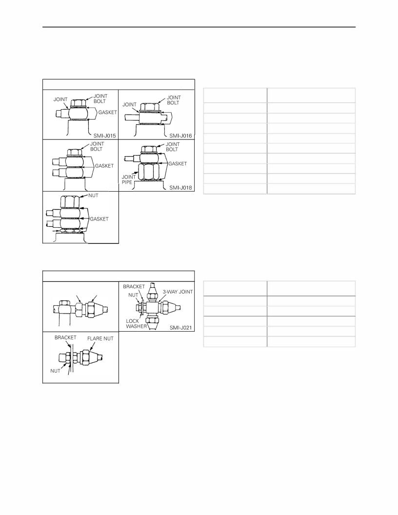
PROCEDURE FOR INSTALLING JOINTS AND |
Hino K13D |
|
|
GASKETS OF ENGINE PIPE |
1. Gasket seal type (aluminum + rubber, asbestos or copper).
Location of gasket seal
GASKET
SMI-J017
SMI-J019
Tightening torque chart |
|
|
|
|
|
Clamping screw size |
|
Tightening torque N-m |
(Diameter) mm{in.} |
|
{kgf-cm, lbf-ft} |
8{0.315} |
|
13{130,9} |
10{0.394} |
|
20{200,14} |
12{0.472} |
|
25{250,18} |
14{0.551} |
|
25{250,18} |
16{0.630} |
|
29{300, 22} |
18{0.709} |
|
39{400,29} |
20{0.787} |
|
*39{400,29} |
24{0.945} |
|
69{700, 51} |
28{1.102} |
|
127{1,300, 94} |
|
|
|
2. Metal seal type (Flare connector type).
Location of metal seal
CONNECTOR FLARE NUT
SMI-J020
Tightening torque chart
Clamping screw size |
Tightening torque N-m |
(Diameter) mm{in.} |
{kgf-cm, lbf-ft} |
12{0.472} |
20{200, 14} |
|
|
14{0.551} |
31{320,23} |
|
|
16{0.630} |
39{400,29} |
18{0.709} |
59{600,43} |
20{0.787} |
64{650,47} |
|
|
LOCK WASHER SMI-J022

GENERAL INTRODUCTION |
Gl-13 |
Hino K13C
Hino K13D
3. Metal seal type (Nipple connector type)
Location of metal seal
GASKET NUT
FLARE cdNNECTOR FL NECTOR CONNECTOR SMIJ023- CONNECTOR SMI-J024
Tightening torque chart
Clamping screw size |
Tightening torque |
(Diameter) |
N-m{kgf-cm, lbf-ft} |
mm{in.} |
|
10{0.394} |
11{110,8} |
|
|
20{0.787} |
20{200, 14} |
|
|
NOTE: o Before installing the joints, ensure that there is no dirt or burrs adhering to the various seat faces (pipe joints, gaskets, etc.)
oBecause the pipes can move relatively freely during installation and the seat faces are liable to tilt, first temporarily tighten the pipes, then tighten them to the specified torque and ensure that there is no leakage from them.
oWhen tightening two pipes together, be very careful that they do not rotate together.
oAfter installing the pipes, apply the correct pressure to each pipe joint and ensure that there is no leakage.
oEnsure that the various tightening torques conform to the above table.
*If a soft washer #4840 FR-N (aluminum + rubber and carbon press fit part) is loosened or removed subsequent to being installed, be sure and replace it with a new one.
There is no need to replace it, however, for normal retightening.

|
HIND |
|
|
|
RECOMMENDED LUBRICANTS FOR ALL HINO ENGINE |
|
|
|
|
HINO MOTORS LTD. |
|||||||||||||
|
|
|
|
|
|
|
|
|
|
|
|
||||||||||||
|
|
|
|
|
|
|
|
|
|
|
|
|
|
|
|
|
|
|
|
|
|
|
TOKYO, JAPAN |
|
LUBRICANTS |
|
POSITIONS |
|
ATMOSPHERIC |
|
S.A.E. |
|
BP |
CALTEX |
|
CASTROL |
|
ESSO |
|
GULF |
|
MOBIL |
SHELL |
|
TOTAL |
||
|
|
|
|
|
|
|
|
|
|
||||||||||||||
|
|
|
|
TEMP. |
|
NO. |
|
|
|
|
|
|
|||||||||||
|
|
|
|
|
|
|
|
|
|
|
|
|
|
|
|
|
|
|
|
|
|
||
|
|
|
|
|
|
Above |
|
|
|
|
RPM DELO 400 Oil |
|
Castrol or Deusol |
|
Essolube |
|
|
|
Mobil Delvac 1340 |
Myrina Oil 40, |
TOTAL |
||
|
|
|
|
|
|
|
40 |
|
Vanellus C-3 |
SAE 40, Or 15W/40 |
|
CRD 40 Turbomax |
|
|
Gulf Super Duty |
|
20W-40, 15W-40 |
Rubia S 40 |
|||||
|
|
|
|
|
|
32" C |
|
|
|
|
D-3 40. |
|
|
Mobil Delvac Super |
|||||||||
|
|
|
|
|
|
|
|
|
40 |
RPM DELO 300 Oil |
|
Castrol or Deusol |
|
|
Motor Oil 40, 15W-40 |
|
Aimura X Oil 40 |
TOTAL |
|||||
|
|
|
|
|
|
(90" Fl |
|
|
|
|
|
XD-3 40 |
|
|
15W-40 |
||||||||
|
|
|
|
|
|
|
|
|
|
SAE 40 |
|
RX Super 40. 15W/40 |
|
|
|
|
|
Rimura CT 40 |
Rubia TM 15W40 |
||||
|
|
|
|
|
|
|
|
|
|
|
|
|
|
|
|
|
|
|
|||||
|
ENGINE OIL |
|
|
|
|
|
|
|
|
|
|
RPM DELO 400 Oil |
|
Castrol or Deusol |
|
|
|
|
|
|
Myrina Oil 30, |
TOTAL |
|
|
(AP.I. CDJ |
|
|
|
|
32• |
-o· |
|
|
|
Vanellus C-3 |
|
|
Essolube |
|
|
|
Mobil Delvac 1330 |
20W-40, 15W-40 |
||||
|
|
|
|
|
|
30 |
|
SAE 30, or 15W/40 |
|
CAD 30 |
|
|
Gulf Super Duty |
|
Rubia S 30 |
||||||||
|
Previous Classification |
|
|
|
|
|
|
|
|
|
D-3 30, |
|
|
Mobil Delvac Super |
Rimura X Oil 30, |
||||||||
|
|
|
|
|
(90" -32' Fi |
|
|
|
30 |
RPM DELO 300 Oil |
|
Castrol or Deusol |
|
|
Motor Oil 30, 15W-40 |
|
TOTAL |
||||||
|
(AP.I. OS) |
|
|
|
|
|
|
|
|
|
XD-3 30 |
|
|
15W-40 |
10W-30 |
||||||||
|
|
|
|
|
|
|
|
|
|
|
SAE 30 |
|
AX Super 30, 15W/40 |
|
|
|
|
Rubia TM 15W40 |
|||||
|
IMIL-L-2104CJ |
|
|
|
|
|
|
|
|
|
|
|
|
|
|
|
|
|
|
|
Rimura CT 30 |
|
|
|
(Mll·l·45199B) |
|
|
|
|
|
° |
|
|
|
|
RPM DELO 400 Oil |
|
Castrol or Deusol |
|
Essolube |
|
|
|
Mobil Delvac 1310 |
Myrina Oil 20, |
TOTAL |
|
|
|
|
|
|
|
|
|
|
|
|
|
CRD 20W/20 |
|
|
|
|
|||||||
|
|
|
|
|
|
o• ~·12 C |
|
|
|
Vanellus C-3 |
SAE 'l0/20W, 15W/40 |
|
|
|
Gulf Super Duty |
|
20W-40, 15W-40 |
i |
a S 20 |
||||
|
|
|
|
|
|
|
20 |
|
|
Castrol or Deusol |
|
D-3 20W, |
|
|
Mobil Delvac Super |
Rub |
|||||||
|
|
|
|
|
|
(32" ~10'F) |
|
|
20W |
RPM DELO 300 Oil |
|
|
|
Motor Oil 20, 15W-40 |
|
Rimura X Oil 20 |
TOTAL |
||||||
|
|
|
|
|
|
|
|
|
|
RX Super 20W/20 |
|
XD·3 15W•40 |
|
|
15W•40 |
||||||||
|
|
Cylinder Block |
|
|
|
|
|
|
|
SAE 20/20W |
|
|
|
|
|
Rimura CT 20 |
Rubia TM 15W40 |
||||||
|
|
|
|
|
|
|
|
|
|
15W/40 |
|
|
|
|
|
|
|||||||
|
|
Injection Pump |
|
|
|
|
|
|
|
|
|
|
|
|
|
|
|
|
|
|
|||
|
|
Ai r Cleaner |
|
|
Above |
|
|
|
|
RPM DELO 200 Oil |
|
Castrol or Deusol |
|
Essolube |
|
|
|
|
Rotella TX40, 20W-50 |
TOTAL |
|||
|
|
|
|
|
|
|
|
|
Vanellus M |
SAE 40 |
|
CRX 40 |
|
|
Gulflube Mater Oil |
|
Mobil Delvac 1240 |
||||||
|
|
|
|
|
|
32'C |
|
40 |
|
|
|
HDX 40, |
|
|
Rotella SX Oil 40, |
||||||||
|
|
|
|
|
|
|
|
40 |
RPM DELO 100 Oil |
|
Castrol or Deusol |
|
|
XHD 40, 1SW-40 |
|
Mobil Delvac1140 |
Rubia H 40 |
||||||
|
|
|
|
|
|
(90' Fl |
|
|
|
|
|
HDX Plus 40 |
|
|
20W-40 |
||||||||
|
|
|
|
|
|
|
|
|
|
SAE 40 |
|
RX Super 40.15W/40 |
|
|
|
|
|
|
|
||||
|
|
|
|
|
|
|
|
|
|
|
|
|
|
|
|
|
|
|
|
|
|
||
|
ENGINE OIL |
|
|
|
|
|
|
|
|
|
|
RPM DELO 200 Oil |
|
Castrol or Deusol |
|
|
|
|
|
|
|
|
|
|
tA.P.I. CCI |
|
|
|
|
32" -o• C |
|
|
|
Vanellus M |
|
|
Essolube |
|
Gulflube Mater Oil |
|
Mobil Delvac 1230 |
Rotella TX30, 20W-50 |
TOTAL |
||||
|
|
|
|
|
|
30 |
|
SAE 30 |
|
CRX 30 |
|
|
|
||||||||||
|
Previous Classification |
|
|
|
|
(90" ~32" F) |
|
|
30 |
RPM DELO 100 Oil |
|
Castrol or Deusol |
|
HDX 30, |
|
XHD 30, 15W•40 |
|
Mobil Delvac 1130 |
Rotella sx Oil 30, |
Rubia H 30 |
|||
|
(AP.I. DMJ |
|
|
|
|
|
|
|
|
|
|
SAE 30 |
|
RX Super 30, 15W/40 |
|
HDX Plus 30 |
|
|
|
|
20W-40 |
|
|
|
(Mll·l-46152) |
|
|
|
|
|
|
|
|
|
|
|
|
|
|
|
|
|
|
|
|
|
|
|
(MIL-L-2104B) |
|
|
|
|
|
|
|
|
|
|
RPM DELO 200 Oil |
|
Castrol or Deusol |
|
|
|
|
|
|
|
|
|
|
|
|
|
|
|
o· |
|
|
|
|
|
|
CRX 20W/20 |
|
Essolube |
|
|
|
|
Rotella TX20, 20W-50 |
TOTAL |
||
|
|
|
|
|
|
--12· |
|
|
|
Vanellus M |
SAE 20/20W |
|
|
|
Gulflube Motor Oil |
|
Mobil Delvac 1220 |
||||||
|
|
|
|
|
|
|
|
20 |
|
|
Castrol or Deusol |
|
HDX 20, |
|
|
RoteIla SX OiI |
|||||||
|
|
|
|
|
|
(32" ~10'F) |
|
|
20W |
i |
|
|
|
XHD 20, 1SW-40 |
|
i |
Rubia H 20 |
||||||
|
|
|
|
|
|
|
|
|
RPM DELO 100 O l |
|
RX Super 20W/20, |
|
HDX Plus 20W-20 |
|
|
Mob l Delvac 1120 |
20/20W, 20W-40 |
||||||
|
|
|
|
|
|
|
|
|
|
|
|
SAE 20/20W |
|
|
|
|
|
|
|
|
|||
|
|
|
|
|
|
|
|
|
|
|
|
|
15W/40 |
|
|
|
|
|
|
|
|
|
|
|
|
|
|
|
|
|
|
|
|
|
|
|
|
|
|
|
|
|
|
|
|
|
|
|
COOLANT PUMP |
|
|
|
|
|
|
|
|
|
|
Marfak |
|
|
|
Esso |
|
|
|
|
|
TOTAL |
|
|
BEARING GREASE |
Coolant Pump Bearing |
|
|
|
|
|
|
Energrease |
Multipurpose 2 |
|
Castrol LM |
|
Multipurpose |
|
Gulflex Poly |
|
Mobilgrease |
Retinax A |
||||
|
|
|
|
|
|
|
L-2 |
or Marfak |
|
Grease |
|
|
|
MP, 77, MS |
Alvania Grease R2 |
MULTIS 2 |
|||||||
|
(Mll-G-109248) |
|
|
|
|
|
|
|
|
|
|
|
Grease |
|
|
|
|||||||
|
|
|
|
|
|
|
|
|
|
|
All Purpose 2 |
|
|
|
|
|
|
|
|
|
|
||
|
|
g iii utch, |
|
|
|
|
|
|
|
Molytex |
|
|
|
|
|
|
|
|
|
|
|
||
|
STARTER GREASE |
i |
a . |
|
|
|
|
|
|
- |
|
- |
|
- |
|
- |
|
i |
Aero Shell Grease 17 |
|
- |
||
|
Pinion Shift Lever |
|
|
|
|
|
|
|
Grease EP2 |
|
|
|
|
|
|
|
Mob lgrease 29 |
|
|
||||
|
|
& Reduction Gear |
|
|
|
|
|
|
|
|
|
|
|
|
|
|
|
|
|
|
|
||
|
GENERATOR & STARTER |
Generator Bearing |
|
|
|
|
|
|
Energrease |
RPM Grease |
|
- |
|
- |
|
- |
|
Mobilgrease 28 |
Aero Shell Grease 7 |
|
- |
||
|
BEARING GREASE |
|
i |
|
|
|
|
|
|
LT2 |
SRI 2 |
|
|
|
|
|
|
|
|
|
|||
|
Starter Bear ng |
|
|
|
|
|
|
|
|
|
|
|
|
|
|
|
|
|
|||||
|
INJECTION PUMP |
|
|
|
|
|
|
|
|
|
|
Marfak |
|
|
|
Esso |
|
|
|
|
|
TOTAL |
|
|
TIMER GREASE |
Injection Pump Timer |
|
|
|
|
|
|
Energrease |
Multipurpose 2 |
|
Castrol LM |
|
Multipurpose |
|
Gulflex Poly |
|
Mobilgrease |
Retinax A |
||||
|
|
|
|
|
|
|
L-2 |
or Marfak |
|
Grease |
|
|
|
MP, 77, MS |
Alvania Grease R2 |
Mullis EP 1 |
|||||||
|
(MIL·G-109248) |
|
|
|
|
|
|
|
|
|
|
|
Grease |
|
|
|
|||||||
|
|
|
|
|
|
|
|
|
|
|
All Purpose 2 |
|
|
|
|
|
|
|
|
|
|
||
|
|
|
|
|
|
|
|
|
|
|
|
|
|
|
|
|
|
Cruise Master |
|
|
Shellzone (U.S.A.) |
|
|
|
|
|
|
|
|
|
|
|
|
|
|
|
|
i |
|
Esso |
|
|
|
Glycoshell Plus |
|
|
|
|
ANTI FREEZE |
|
|
|
|
|
|
|
|
|
Anti Frost |
AF Engine |
|
Castrol Ant -Freeze |
|
|
Antifreeze |
|
Mobil |
(Europian Countries) |
TOTAL |
||
|
Engine, Radiator |
|
|
|
|
|
|
|
Castrol Long Life |
|
Anti-Freeze |
|
|
||||||||||
|
(Mll-A-53009) |
|
|
|
|
|
|
Coolant |
|
|
|
And Summer |
|
Parmazone |
Shellsafe |
ANTIGEL |
|||||||
|
|
|
|
|
|
|
|
|
|
|
|
Coolant |
|
Coolant |
|
|
|||||||
|
|
|
|
|
|
|
|
|
|
|
|
|
|
|
|
Coolant |
|
|
Anti-Freeze P281 |
|
|
||
|
|
|
|
|
|
|
|
|
|
|
|
|
|
|
|
|
|
|
|
|
Coolguard |
|
|
C')...'
"""
C')l'TI
=2
l'TI
:r::,, rz-
=
C C, C:
:::!
C 2
NOTE: Lubricants were amended according to new classification by AP I (American Petroleum Institute) |
'82 •12 •200 |

ENGINE |
EN-1 |
|
|
EN-Y271E-01
Hino K13C
Hino K13D
CHAPTER EN |
|
|
ENGINE |
|
|
Models K13C-T AND K13D-T |
|
|
DATA AND SPECIFICATION................................................. |
EN - |
3 |
TROUBLESHOOTING ........................................................... |
EN - |
7 |
ENGINE OVERHAUL CRITERIA ........................................... |
EN - 12 |
|
ENGINE MOVING PARTS .................................................... |
EN - 14 |
|
CYLINDER HEAD .......................................................... |
EN - 16 |
|
CRANKSHAFT PULLEY................................................ |
EN - 31 |
|
FLYWHEEL AND FLYWHEEL HOUSING ..................... |
EN - 33 |
|
TIMING GEAR AND CAMSHAFT ................................ |
EN - 36 |
|
INJECTION PUMP DRIVE ............................................ |
EN - 42 |
|
PISTON, CRANKSHAFT, CYLINDER BLOCK |
|
|
AND OIL PAN................................................................ |
EN - 44 |
|
LIQUID GASKET AND APPLICATION POINTS........... |
EN - 61 |
|
LUBRICATING SYSTEM ....................................................... |
EN - 62 |
|
OIL PUMP ..................................................................... |
EN - 66 |
|
OIL COOLER AND OIL FILTER .................................... |
EN - 69 |
|
FUEL SYSTEM ...................................................................... |
EN - 71 |
|
INJECTION NOZZLE .................................................... |
EN - 73 |
|
FUEL INJECTION PUMP.............................................. |
EN - 76 |
|
COOLING SYSTEM............................................................... |
EN - 78 |
|
COOLANT PUMP.......................................................... |
EN - 79 |
|
THERMOSTAT .............................................................. |
EN - 82 |
|
RADIATOR .................................................................... |
EN - 83 |
|
COOLING FAN.............................................................. |
EN - 84 |
|
AIR INTAKE AND EXHAUST SYSTEM................................ |
EN - 87 |
|
ELECTRICAL PARTS ............................................................. |
EN - 90 |
|
GENERATOR................................................................. |
EN - 90 |
|
STARTER....................................................................... |
EN - 91 |
|
ENGINE TUNE-UP ................................................................ |
EN - 92 |
|
ENGINE TUNE-UP ON TEST BENCH.......................... |
EN - 97 |
|


ENGINE |
EN-3 |
|
|
Hino K13C
Hino K13D
DATA AND SPECIFICATION
Model |
|
HINO K13CTB-NSZA, K13CTB-HAJA, K13CTJ-NSAC, K13CTB-EWAA |
|
|
|
|
K13CUC-EWBA, K13CUC-EVBA |
|
|
|
|
Type |
|
Diesel 4 cycle, vertical, 6 cylinder, in-line overhead valve, water-cooled, |
|
|
|
||
|
|
|
direct injection. |
Aspiration |
|
Turbocharged |
|
|
|
|
|
Bore and stroke |
|
135 x 150 mm {5.31 x 5.91 in.} |
|
|
|
|
|
Piston displacement |
12.882 L {786.1 cu.in.} |
||
|
|
|
|
Compression ratio |
|
16.5: 1 (K13CTB-NSZA/HAJA/EWAA/EVBA) |
|
|
|
|
17.6: 1 (K13CTJ-NSAC, K13CUC-EWBA) |
|
|
|
|
Firing order |
|
1-4-2-6-3-5 (The cylinder numbers are counted in order from the timing gear |
|
|
|
|
side.) |
|
|
|
|
Direction of rotation |
Counterclockwise viewed from flywheel |
||
|
|
|
|
Compression pressure |
2.85-3.04 MPa {29-31 kgf/cm2, 413-440 lbf/in2.} at 200 r/min. |
||
Idling revolution |
|
700 - 750 r/min. |
|
|
|
|
|
Dry weight |
|
Approximately 1,050 kg {2,315 lb} (K13TB-NSZA/HAJA/EWAA, K13CTJ- |
|
|
|
|
NSAC, K13CUC-EWBA) |
|
|
|
Approximately 1,040 kg {2,293 lb} (K13CUC-EVBA) |
|
|
|
|
|
|
Intake |
30° |
Valve seat angle |
|
|
|
|
|
Exhaust |
45° |
|
|
Intake |
30° |
Valve face angle |
|
Exhaust |
|
|
|
45° |
|
Valve timing |
|
Intake opens |
14° before top dead center |
(flywheel travel) |
|
Intake closes |
42° after bottom dead center |
|
|
Exhaust opens |
48° before bottom dead center |
|
|
Exhaust closes |
16° after top dead center |
Valve clearance |
|
Intake |
0.40 mm {0.0157 in.} |
|
|
|
|
(when cold) |
|
Exhaust |
0.50 mm {0.0197 in.} |
|
|
||
|
|
|
|
Engine oil pump |
|
|
|
Type |
|
Full forced pressure feed by gear pump |
|
Drive |
|
By gear |
|
|
|
|
|
Engine oil cooler |
|
Multi-plate type, water cooled |
|
|
|
|
|
Injection nozzle |
|
|
|
Type |
|
Multi-hole nozzle type |
|
Valve opening pressure |
21.57 MPa {220 kgf/cm2, 3,128 lbf/in2.} |
||
|
|
|
|
Coolant pump |
|
|
|
Type |
|
Forced circulation by volute pump |
|
Drive |
|
By gear |
|
|
|
|
|
Thermostat |
|
|
|
Type |
|
Wax type, bottom bypass system |
|
|
|
|
|
Hino K13D Engine Parts Contact: |
email EngineParts@HeavyEquipmentRestorationParts.com |
Phone: 269 673 1638 |
Website: www.HeavyEquipmentRestorationParts.com |

EN-4 |
ENGINE |
|
|
Hino K13C
Hino K13D
|
14° before top dead center for No.1 cylinder of the compression stroke |
|
|
(K13CTJ-NSAC. K13CUC-EVBA) |
|
|
|
|
|
18° before top dead center for No.1 cylinder of the compression stroke |
|
Injection timing (flywheel travel) |
(K13CTB-EWAA, K13CUC-EWBA) |
|
|
||
|
19° before top dead center for No.1 cylinder of the compression stroke |
|
|
(K13CTB-NSZA) |
|
|
|
|
|
21° before top dead center for No.1 cylinder of the compression stroke |
|
|
(K13CTB-HAJA) |
|
|
|
|
Injection pump No. |
22020-3641 (K13CTB-NSZA/HAJA). 22020-4931 (K13CTJ-NSAC) |
|
22020-5240 (K13CTB-EWAA), 22020-5320 (K13CUC-EWBA/EVBA) |
||
|
||
|
|
|
Engine oil volume (L) |
L: 16 H: 20 TOTAL: 27 (K13CTB-NSZA/HAJA, K13CTJ-NSAC) |
|
L: 20 H: 40 TOTAL: 45 (K13CTB-EWAA. K13CUC-EWBA/EVBA) |
||
|
||
|
|
ENGINE |
EN-5 |
|
|
Hino K13C
Hino K13D
Model |
|
HINO K13DTA-NSAA, K13DTB-EUAA, K13DTB-EWBB, K13DTB-EWBA, |
|
|
|
|
K13DTB-EVBA |
|
|
|
|
Type |
|
Diesel 4 cycle, vertical, 6 cylinder, in-line overhead valve, water-cooled, |
|
|
|
|
direct injection. |
Aspiration |
|
Turbocharged |
|
|
|
|
|
Bore and stroke |
|
137 x 150 mm {5.39 x 5.91 in.} |
|
|
|
|
|
Piston displacement |
13.267 L {809.6 cu.in.} |
||
|
|
|
|
Compression ratio |
|
16.5: 1 |
|
|
|
|
|
Firing order |
|
1-4-2-6-3-5 (The cylinder numbers are counted in order from the timing gear |
|
|
|
|
side.) |
|
|
|
|
Direction of rotation |
Counterclockwise viewed from flywheel |
||
|
|
|
|
Compression pressure |
2.8-3.0 MPa {29-31 kgf/cm2, 412-440 lbf/in.2} at 200 r/min. |
||
Idling revolution |
|
700 - 750 r/min. |
|
|
|
|
|
Dry weight |
|
Approximately 1,050 kg {2,315 lb} (K13DTA-NSAA) |
|
|
Approximately 1,065 kg {2,348 lb} (K13DTB-EUAA, K13DTB-EWBB/EWBA) |
||
|
|
|
|
|
|
|
Approximately 1,067 kg {2,352 lb} (K13DTB-EVBA) |
|
|
|
|
|
|
Intake |
30° |
Valve seat angle |
|
|
|
|
|
Exhaust |
45° |
Valve face angle |
|
Intake |
30° |
|
Exhaust |
|
|
|
|
45° |
|
Valve timing |
|
Intake opens |
14° before top dead center |
(flywheel travel) |
|
Intake closes |
42° after bottom dead center |
|
|
||
|
|
Exhaust opens |
48° before bottom dead center |
|
|
Exhaust closes |
16° after top dead center |
Valve clearance |
|
Intake |
0.40 mm {0.0157 in.} |
|
|
|
|
(when cold) |
|
Exhaust |
0.40 mm {0.0157 in.} |
|
|
||
|
|
|
|
Engine oil pump |
|
|
|
Type |
|
Full forced pressure feed by gear pump |
|
Drive |
|
By gear |
|
|
|
|
|
Engine oil cooler |
|
Multi-plate type, water cooled |
|
|
|
|
|
Injection nozzle |
|
|
|
Type |
|
Multi-hole nozzle type |
|
Valve opening pressure |
19.6 MPa {200 kgf/cm2, 2,844 lbf/in.21 |
||
|
|
|
|
Coolant pump |
|
|
|
Type |
|
Forced circulation by volute pump |
|
Drive |
|
By gear |
|
|
|
|
|
Thermostat |
|
Wax type, bottom bypass system |
|
Type |
|
||
|
|
||
|
|
|
|
Hino K13D Engine Parts Contact: |
email EngineParts@HeavyEquipmentRestorationParts.com |
Phone: 269 673 1638 |
Website: www.HeavyEquipmentRestorationParts.com |

EN-6 |
ENGINE |
|
|
Hino K13C
Hino K13D
|
16° before top dead center for No.1 cylinder of the compression stroke |
|
Injection timing (flywheel travel) |
(K13DTA-NSAA, K13DTB-EUAA, K13DTB-EWBA/EVBAI |
|
|
||
|
18° before top dead center for No.1 cylinder of the compression stroke |
|
|
(K13DTB-EWBB) |
|
Injection pump No. |
22020-4920 (K13DTA-NSAA), 22020-5450 (K13DTB-EUAA, K13DTB-EVBA), |
|
22020-5800 (K13DTB-EWBB), 22020-5480 (K13DTB-EWBA) |
||
|
||
|
|
|
|
L: 20 H: 40 TOTAL: 47 (K13DTA-NSAA), |
|
Engine oil volume (LI |
L: 16 H: 20 TOTAL: 25 (K13DTB-EUAA), |
|
L: 20 H: 40 TOTAL: 45 (K13DTB-EWBB/EWBA) |
||
|
||
|
L: 16 H: 20 TOTAL: 27 (K13DTB-EVBA) |
|
|
|

|
|
|
|
|
|
|
ENGINE |
|
|
EN-7 |
||
|
|
|
|
|
|
|
|
|
|
|
|
|
Hino K13C |
|
|
|
|
|
|
|
|
|
|
||
Hino K13D |
|
|
|
|
|
|
|
|
|
|
||
|
|
|
TROUBLESHOOTING |
|
|
|
||||||
Symptom |
Possible cause |
Remedy/Prevention |
||||||||||
|
|
|
|
|
|
|
|
|
|
|
|
|
Engine overheating _ _ _ ___, |
Coolant |
|
|
|
|
|||||||
|
|
• |
|
...........................................Insufficient coolant |
Add coolant. |
|||||||
|
|
• |
Defective thermostat ........................................ |
|
Replace the thermostat. |
|||||||
|
|
• |
Overflow of coolant due to leakage of ............ |
|
Repair. |
|||||||
|
|
|
exhaust into cooling system |
|
|
|
||||||
|
|
• |
Coolant leakage from cylinder head gasket ... |
|
Replace gasket. |
|||||||
|
|
• |
|
Defective coolant pump ................................... |
|
Repair or replace. |
||||||
|
|
|
Radiator |
|
|
|
||||||
|
|
• |
Clogged with rust and scale ............................. |
Clean radiator. |
||||||||
|
|
• Clogged with iron oxide due to leakage ......... |
Clean coolant passage and |
|||||||||
|
|
|
of exhaust into cooling system |
correct exhaust leakage. |
||||||||
|
|
• Clogged radiator core due to mud .................. |
Clean radiator. |
|||||||||
|
|
|
or other debris |
|
|
|
||||||
|
|
• Defective radiator cap pressure valve ............. |
|
Replace radiator cap. |
||||||||
|
|
|
Abnormal combustion |
|
|
|
||||||
|
|
|
|
|
|
|
|
|
|
|
|
|
|
|
• |
Incorrect injection timing ................................. |
Adjust injection timing. |
||||||||
|
|
• |
|
Reduced injection pressure .............................. |
Adjust injection pressure. |
|||||||
|
|
• |
|
Poor fuel ............................................................ |
|
Use good quality fuel. |
||||||
|
|
• |
|
Poor nozzle spray .............................................. |
Adjust or replace nozzle. |
|||||||
|
|
• Unsatisfactory automatic timer advance angle .Repair or replace timer. |
||||||||||
|
|
|
Other problems |
|
|
|
||||||
|
|
• Defective or deteriorated engine oil ................ |
|
Change engine oil. |
||||||||
|
|
• |
|
Unsatisfactory operation of oil pump ............. |
|
Replace or repair. |
||||||
|
|
• |
|
Insufficient oil .................................................... |
Add oil. |
|||||||
|
|
|
|
|
|
|
|
|
|
|
|
|
|
|
|
|
|
|
|
|
|
|
|
|
|
Excessive oil consumption-- -, Pistons, cylinder liners, and piston rings
• |
Wear of piston ring and cylinder liner ............. |
Replace piston rings and |
|
|
cylinder liner. |
• Worn, sticking or broken piston rings ............. |
Replace piston rings and |
|
|
|
cylinder liner. |
• |
Insufficient tension on piston rings ................. |
Replace piston rings and |
|
|
cylinder liner. |
• |
Unsatisfactory break-in of piston rings ........... |
Replace piston rings and |
|
|
cylinder liner. |
• |
Unsuitable oil (viscosity too low) .................... |
Change oil as required and |
|
|
replace piston rings and cylin |
|
|
der liners. |
• |
Incorrectly fitted piston rings ........................... |
Replace piston rings. |
|
(upside down) |
|
• Gaps of piston rings in line with each other ... |
Reassemble piston rings. |
|
EN-8 |
ENGINE |
Hino K13C
Hino K13D
Symptom |
|
|
|
Possible cause |
Remedy/Prevention |
|||||||||
|
|
|
|
|
|
|
|
|
|
|
|
|
|
|
Excessive oil consumption-- -1 Valve and valve guides |
|
|
||||||||||||
|
|
|
• |
Worn valve steam ............................................. |
Replace valve and valve guide. |
|||||||||
|
|
|
• |
Worn valve guide .............................................. |
Replace valve guide. |
|||||||||
|
|
|
• |
Incorrectly fitted valve stem seal ..................... |
Replace the stem seal. |
|||||||||
|
|
|
• Excessive lubricant on rocker arm .................. |
Check clearance of rocker arm |
||||||||||
|
|
|
|
|
|
|
|
|
|
|
|
|
and shaft. |
|
|
|
|
|
|
|
|
|
|
|
|
|
|
|
|
|
|
|
|
|
Excess oil feed |
|
|
|||||||
|
|
|
• |
Defective oil level gauge .................................. |
Replace oil level gauge. |
|||||||||
|
|
|
• |
Oil level too high ............................................... |
Drain excess oil. |
|||||||||
|
|
|
|
|
Other problems |
|
|
|||||||
|
|
|
• |
Overcooled engine (low temperature wear) ... |
Warm up engine. Check cool |
|||||||||
|
|
|
|
|
|
|
|
|
|
|
|
|
ing system. |
|
|
|
|
• |
Oil leakage from miscellaneous parts ............. |
Repair. |
|||||||||
|
|
|
|
|
|
|
|
|
|
|
|
|
|
|
----------Piston seizure |
|
,----, |
Operation |
|
|
|||||||||
|
|
|
||||||||||||
|
|
|
|
|
|
|
|
|
|
|
|
|
||
|
|
|
• Abrupt stoppage of engine .............................. |
Operate engine properly. |
||||||||||
|
|
|
• |
Insufficient oil .................................................... |
Add oil. |
|||||||||
|
|
|
• |
Dirty oil .............................................................. |
Change oil. |
|||||||||
|
|
|
• |
Poor quality oil .................................................. |
Replace with proper engine oil. |
|||||||||
|
|
|
• |
High oil temperature......................................... |
Repair. |
|||||||||
|
|
|
• |
Low oil pressure ................................................ |
Repair. |
|||||||||
|
|
|
• |
Defective oil pump ............................................ |
Repair oil pump. |
|||||||||
|
|
|
• |
Reduced performance due to worn oil ........... |
Replace oil pump. |
|||||||||
|
|
|
|
|
pump |
|
|
|||||||
|
|
|
• Suction strainer sucking air ............................. |
Add oil and/or repair strainer. |
||||||||||
|
|
|
|
|
|
|
|
|||||||
|
|
|
|
|
Abnormal combustion ..................................... |
See Symptom: "Engine over |
||||||||
|
|
|
|
|
|
|
|
|
|
|
|
|
heating". |
|
|
|
|
|
|
Coolant ............................................................. |
See Symptom: "Engine over |
||||||||
|
|
|
|
|
|
|
|
|
|
|
|
|
heating". |
|
|
|
|
|
|
|
|
|
|
|
|
|
|
||
|
|
|
|
|
|
|
|
|
|
|||||
Lack of power------- -1 Injection pump .................................................. |
Refer to CHAPTER IP, FUEL |
|||||||||||||
|
|
|
|
|
|
|
|
|
|
|
|
|
INJECTION PUMP. |
|
|
|
|
|
|
|
|
|
|
|
|
||||
|
|
|
|
|
Intake |
|
|
|||||||
|
|
|
• |
Clogged air cleaner ........................................... |
Clean element or replace |
|||||||||
|
|
|
|
|
|
|
|
|
|
|
|
|
element. |
|
|
|
|
|
|
Overheating ..................................................... |
See Symptom: "Engine over |
||||||||
|
|
|
|
|
|
|
|
|
|
|
|
|
heating". |
|

|
|
|
ENGINE |
|
EN-9 |
|
|
|
|
|
|
Hino K13C |
|
|
|
|
|
Hino K13D |
|
|
|
|
|
Symptom |
|
Possible cause |
Remedy/Prevention |
||
|
|
|
|
|
|
Lack of power------- |
-1 Fuel and nozzle |
|
||||||||||
|
|
|
• |
|
|
Poor nozzle spray .............................................. |
Adjust or replace injection |
|||||
|
|
|
|
|
|
|
|
|
|
|
|
nozzle. |
|
|
|
• |
Clogged nozzle with carbon ............................. |
Clean nozzle. |
|||||||
|
|
|
• |
Wear or seizure of nozzle ................................. |
Replace nozzle. |
|||||||
|
|
|
• Air in fuel system .............................................. |
Repair and bleed air from fuel |
||||||||
|
|
|
|
|
|
|
|
|
|
|
|
system. |
|
|
|
• |
Clogged fuel filter ............................................. |
Replace element. |
|||||||
|
|
|
• Use of poor fuel ................................................ |
Use good quality fuel. |
||||||||
|
|
|
|
|
......................................Abnormal combustion |
See Symptom: "Engine over |
||||||
|
|
|
|
|
|
|
|
|
|
|
|
heating". |
|
|
|
|
|
|
|
|
|
|
|
|
|
|
|
|
|
|
Piston, cylinder liners, and piston rings |
......... See Symptom: "Engine over |
||||||
|
|
|
|
|
|
|
|
|
|
|
|
heating". |
|
|
|
|
|
|
|
|
|
|
|
|
|
|
|
|
|
|
Other problems |
|
||||||
|
|
|
|
|
|
|
|
|
|
|||
|
|
|
• |
Breakage of turbine or blower ......................... |
Refer to CHAPTER TU, |
|||||||
|
|
|
|
|
|
|
|
|
|
|
|
TURBOCHAGER. |
|
|
|
|
|
|
|
|
|
|
|
||
Difficult starting engine _____ |
|
, Electrical system |
|
|||||||||
|
|
|||||||||||
|
|
|
• |
|
|
Discharged battery............................................ |
Charge battery. |
|||||
|
|
|
• Defective wiring in starter circuit..................... Repair wiring of starter. |
|||||||||
|
|
|
• |
|
|
Loose or open-circuit battery cable ................. |
nghten battery terminal |
|||||
|
|
|
|
|
|
|
|
|
|
|
|
connections or replace battery |
|
|
|
|
|
|
|
|
|
|
|
|
cable. |
|
|
|
• |
Breakdown of starter ........................................ |
Replace starter. |
|||||||
|
|
|
• Break of intake air heater ................................. |
Replace. |
||||||||
|
|
|
|
|
(If so equipped) |
|
||||||
|
|
|
|
|
Injection pump |
Refer to CHAPTER IP, FUEL |
||||||
|
|
|
|
|
||||||||
|
|
|
|
|
|
|
|
|
|
|
|
INJECTION PUMP. |
|
|
|
|
|
Air cleaner |
|
||||||
|
|
|
• |
Clogged element ............................................... |
Clean the element or replace |
|||||||
|
|
|
|
|
|
|
|
|
|
|
|
the element. |
|
|
|
|
|
|
|
|
|
|
|
||
|
|
|
|
|
Fuel system |
|
||||||
|
|
|
|
|
|
|
||||||
|
|
|
• No fuel in tank ................................................... |
Supply fuel and bleed air from |
||||||||
|
|
|
|
|
|
|
|
|
|
|
|
fuel system. |
|
|
|
• |
Clogged fuel line ............................................... |
Clean fuel line. |
|||||||
|
|
|
• Air sucked into fuel system through ............... |
Tighten fuel line connections. |
||||||||
|
|
|
|
fuel line connections |
|
|||||||
|
|
|
• |
Clogged fuel filter ............................................. |
Replace element. |
|||||||
|
|
|
• Loose connection in high-pressure line .......... |
Tighten sleeve nut of high |
||||||||
|
|
|
|
|
|
|
|
|
|
|
|
pressure line. |
|
|
|
• |
Water in fuel ...................................................... |
Drain and clean fuel system. |
|||||||

EN-10 |
ENGINE |
Hino K13C
Hino K13D
Symptom |
|
|
Possible cause |
Remedy/Prevention |
||||||||||||
|
|
|
|
|
|
|
|
|
|
|
|
|
|
|
|
|
|
Difficulty starting engine--- -j Nozzles.. |
|
|
|
||||||||||||
|
|
|
|
• |
Seized nozzle ..................................................... |
Replace nozzle. |
||||||||||
|
|
|
|
• |
|
Broken or fatigued nozzle spring ..................... |
Replace spring. |
|||||||||
|
|
|
|
|
|
Oil system |
|
|
|
|||||||
|
|
|
|
• Oil viscosity too high ........................................ |
|
Use proper viscosity oil, or |
||||||||||
|
|
|
|
|
|
|
|
|
|
|
|
|
|
install an oil immersion heater |
||
|
|
|
|
|
|
|
|
|
|
|
|
|
|
and warm up oil. |
||
|
|
|
|
|
|
|
|
|
|
|
|
|
|
|
|
|
|
|
|
|
|
|
Other problems |
|
|
|
|||||||
|
|
|
|
• |
Seized piston ..................................................... |
Replace piston, piston rings, |
||||||||||
|
|
|
|
|
|
|
|
|
|
|
|
|
|
and liner. |
||
|
|
|
|
• |
|
Seized bearing ................................................... |
Replace bearing and/or crank |
|||||||||
|
|
|
|
|
|
|
|
|
|
|
|
|
|
shaft. |
||
|
|
|
|
• |
Reduced compression pressure ...................... |
|
Overhaul engine. |
|||||||||
|
|
|
|
• |
Ring gear damaged or worn ............................ |
Replace the ring gear and/or |
||||||||||
|
|
|
|
|
|
|
|
|
|
|
|
|
|
starter pinion. |
||
|
|
|
|
• |
|
Improperly adjusted or broken ........................ |
Adjust or replace the |
|||||||||
|
|
|
|
|
accelerator cable |
accelerator cable. |
||||||||||
|
|
|
|
|
|
|
|
|
|
|
|
|
||||
Rough idling------- ---< Injection pump .................................................. |
Refer to CHAPTER IP, FUEL |
|||||||||||||||
|
|
|
|
|
|
|
|
|
|
|
|
|
|
|
INJECTION PUMP. |
|
|
|
|
|
|
|
|
|
|
|
|
|
|
|
|||
|
|
|
|
|
|
Nozzles |
|
|
|
|||||||
|
|
|
|
|
|
|
|
|
|
|
|
|
|
|||
|
|
|
|
• |
Uneven injection pressure ............................... |
Adjust. |
||||||||||
|
|
|
|
• |
|
Poor nozzle spray .............................................. |
Adjust or replace nozzle. |
|||||||||
|
|
|
|
• |
Carbon deposit on nozzle tip ........................... |
Remove carbon. |
||||||||||
|
|
|
|
• |
Seized needle valve .......................................... |
Replace nozzle. |
||||||||||
|
|
|
|
|
Engine proper |
|
|
|
||||||||
|
|
|
|
• |
|
Improper valve clearance ................................. |
Adjust valve clearance. |
|||||||||
|
|
|
|
• |
Improper contact of valve seal ........................ |
Replace or repair valve and |
||||||||||
|
|
|
|
|
|
|
|
|
|
|
|
|
|
valve seat. |
||
|
|
|
|
• Idling speed too low ......................................... |
Adjust idling speed. |
|||||||||||
|
|
|
|
• |
Coolant temperature too low ........................... |
Warm up engine. |
||||||||||
|
|
|
|
• |
Compression pressure of cylinders................. |
|
Overhaul engine. |
|||||||||
|
|
|
|
|
markedly different from one another |
|
|
|
||||||||
|
|
|
|
|
|
|
|
|
|
|
|
|||||
Leakage of exhaust gas |
--- 1 Cylinder head gasket-- |
|
|
|
||||||||||||
|
|
|
|
|
|
|
|
|
||||||||
|
|
|
|
• |
|
Fatigued gasket (aging) .................................... |
Replace gasket. |
|||||||||
|
|
|
|
• |
|
Damage.............................................................. |
Replace gasket. |
|||||||||
|
|
|
|
• |
Improper installation ........................................ |
Replace gasket. |
||||||||||

ENGINE |
EN-11 |
|
|
Hino K13C
Hino K13D
Symptom |
|
|
|
Possible cause |
Remedy/ Prevention |
|||||||
|
|
|
|
|
|
|
|
|
|
|
|
|
Leakage of exhaust----- |
.,......... |
Cylinder head bolts |
|
|
|
|||||||
|
|
|
• |
|
........................................................Loose bolts |
Tighten bolt. |
||||||
|
|
|
• |
|
Elongated bolts ................................................. |
Replace bolt. |
||||||
|
|
|
• |
Improper tightening torque or ......................... |
Tighten properly. |
|||||||
|
|
|
|
|
tightening sequence |
|
|
|
||||
|
|
|
|
|
Cylinder block |
|
|
|
||||
|
|
|
• |
Cracking ............................................................. |
Replace cylinder block. |
|||||||
|
|
|
• |
Surface distortion ............................................. |
|
Repair or replace. |
||||||
|
|
|
• Fretting of cylinder liner insertion ................... |
|
Replace cylinder liner or |
|||||||
|
|
|
|
|
portion (insufficient projection of |
cylinder block. |
||||||
|
|
|
|
|
cylinder liner) |
|
|
|
||||
|
|
|
|
|
|
|
|
|
|
|
|
|
|
|
|
|
|
Cylinder head |
|
|
|
||||
|
|
|
• |
Cracking ............................................................. |
|
Replace cylinder head. |
||||||
|
|
|
• |
Surface distortion ............................................. |
|
Repair or replace. |
||||||
|
|
|
|
|
Cylinder liners |
|
|
|
||||
|
|
|
• |
Cracking ............................................................. |
|
Replace cylinder liner. |
||||||
|
|
|
• |
Corrosion ........................................................... |
|
Replace cylinder liner. |
||||||
|
|
|
• |
|
Insufficient projection of cylinder liner ........... |
|
Replace cylinder liner. |
|||||
|
|
|
|
|
Other problems |
|
|
|
||||
|
|
|
• |
|
Incorrect injection timing ................................. |
Adjust injection timing. |
||||||
|
|
|
|
|
|
|
|
|
|
|
|
|

EN-12 |
ENGINE |
|
|
Hino K13C |
ENGINE OVERHAUL CRITERIA |
Hino K13D |
SPECIAL TOOL
Prior to starting an engine overhaul, it is necessary to have these special tools.
COMPRESSION GAUGE |
COMPRESSION GAUGE |
ADAPTER |
ADAPTER |
ST-0246 |
|
ST-0003 |
|
|
|
09508-1030
EXAMPLE
09552-1030 , 09552-1060
|
FACTORS TO DETERMINE THE ENGINE OVERHAUL |
|
|
||
|
LOW COMPRESSION PRESSURE |
|
|
a. |
Before measurement |
|
a) Set the valve clearance to the correct value. |
|
|
b) Idle the engine (Water temperature at 80° C {176° F}). |
|
|
c) |
Charge the battery fully. |
|
d) Remove the air cleaner. |
|
|
b. |
Measurement |
SM3-F0001 |
a) Remove the nozzle holders. |
|
|
b) Install the gauge adapter in the nozzle holder hole. |
|
|
Special Tools: Compression Gauge Adapter (09508-10301 |
|
|
|
(09552-10301 |
|
|
(09552-10601 |
|
c) |
Disconnect the engine stop link rod from engine stop lever |
|
|
of the injection pump and secure it to the engine stop |
|
|
position with tape or string. |
d) Connect a compression gauge to the gauge adapter.
e) Drive the engine with the starter and read the compression pressure.
NOTE: Do not continuously operate the starter for more than 15 seconds at a time.
f)Measure the compression pressure for each cylinder. If the compression pressure is low, be sure to repeat the measur ing.
NOTE: Be sure not to leak through sealing face.
Unit: MPa {kgf/cm', lbf/in'.}
Engine models |
Compression pressure |
Difference between |
Engine speed |
||
Standard |
Limit |
each cylinder |
Ir/min) |
||
|
|||||
K13C-T, K13D-T |
2.85-3.04 {29-31, 413-440} |
2.65 {27, 384} |
Less than |
200 |
|
|
|||||
|
0.34 {3.43, 48.77} |
||||
|
|
|
|
||
|
|
|
|
|
|

Hino K13C |
|
|
Hino K13D |
ENGINE |
EN-13 |
|
r----7
|
6 |
I |
lI I |
||
I |
OIL |
I |
I |
I |
|
L ____ _J
SM3-F0002
|
ATMOSPHERIC TEMPERATURE |
|||||
S.A.E. |
|
|
|
|
|
|
GRADE -10 O |
32 |
50 |
70 |
90 100 |
°F |
|
-23-18 |
0 |
10 |
21 |
32 39 |
°C |
|
40 |
|
|
|
|
|
|
30
20W-20
15W-40
DECREASED OIL PRESSURE
Check the oil pressure warning lamp when the oil and cool ant temperature is hot [about 80°C {176° F}J.
a.If the warning lamp is lighted, check the oil level.
b.Check oil deterioration.If oil quality is poor, replace with a suitable grade oil.
c.Remove the oil pressure switch and install the oil pressure gauge.
d.Measure the oil pressure at coolant temperature 80°C {176°F} or more.
Standard oil pressure: 49-490 kPa
{0.5-5.0 kgf/cm2, 7.11-71.10 lbf/in.2} Service limit: Less than 49 kPa {0.5 kgf/cm2, 7.11 lbf/in.2}
OTHER FACTORS
a.The blowby gas increases.
b.The engine does not start easily. C. Engine output decreases.
d.Fuel consumption increases.
e.Engine make greater noise.
f.Excessive oil consumption.

EN-14 |
ENGINE |
|
|
Hino K13C
Hino K13D
ENGINE MOVING PARTS
DESCRIPTION
Model: K13C-T
1
2
5
6
7
 3
3
8 |
|
4 |
|
9
1.
2.
3. 4. 5. 6. 7. 8. 9. 10. 11. 12. 13. 14. 15. 16.
17.
18.
19.
Fuel injection nozzle Generator
Engine oil filler cap Tension pulley Turbocharger Exhaust manifold Cooling fan pulley Coolant pump Crankshaft pulley Fuel filter
Fuel injection pump Intake manifold Inspection hole Engine oil level gauge Oil pan
Water separator (If so equipped)
Engine oil drain plug Oil filter (Fuel flow) Oil filter (Bypass)
S6-K13-0001A
14 |
15 |
16 |
17 |
18 |
19 |
 Loading...