


 Loading...
Diesel Injection Pump
SERVICE MANUAL
Common Rail System for HINO Dutro / TOYOTA Dyna N04C-T# Type Engine
OPERATION
November, 2003
00400058E
|
|
TABLE OF CONTENTS |
|
1. |
Product Application List . . . . . . . . . . . . . . . . . . . . . . . . . . . . . . . . . . . . . . . . . . . . . . . . . . . . . . . . . . . . . . . . . . . . . . . . . . . . . . . . |
1 |
|
|
1-1. |
Vehicle Specifications . . . . . . . . . . . . . . . . . . . . . . . . . . . . . . . . . . . . . . . . . . . . . . . . . . . . . . . . . . . . . . . . . . . . . . . . . . . . . . |
1 |
|
1-2. |
Component Part Numbers . . . . . . . . . . . . . . . . . . . . . . . . . . . . . . . . . . . . . . . . . . . . . . . . . . . . . . . . . . . . . . . . . . . . . . . . . . . |
1 |
2. |
Common Rail System Outline . . . . . . . . . . . . . . . . . . . . . . . . . . . . . . . . . . . . . . . . . . . . . . . . . . . . . . . . . . . . . . . . . . . . . . . . . . . . |
2 |
|
|
2-1. |
Background to Development . . . . . . . . . . . . . . . . . . . . . . . . . . . . . . . . . . . . . . . . . . . . . . . . . . . . . . . . . . . . . . . . . . . . . . . . |
2 |
|
2-2. |
System Characteristics . . . . . . . . . . . . . . . . . . . . . . . . . . . . . . . . . . . . . . . . . . . . . . . . . . . . . . . . . . . . . . . . . . . . . . . . . . . . . |
2 |
|
2-3. Comparison to The Conventional System . . . . . . . . . . . . . . . . . . . . . . . . . . . . . . . . . . . . . . . . . . . . . . . . . . . . . . . . . . . . . . |
3 |
|
3. |
Outline of TOYOTA / HINO Small Truck Common Rail System . . . . . . . . . . . . . . . . . . . . . . . . . . . . . . . . . . . . . . . . . . . . . . . . |
4 |
|
|
3-1. |
Main System Components . . . . . . . . . . . . . . . . . . . . . . . . . . . . . . . . . . . . . . . . . . . . . . . . . . . . . . . . . . . . . . . . . . . . . . . . . . |
4 |
|
3-2. Outline of Composition and Operation . . . . . . . . . . . . . . . . . . . . . . . . . . . . . . . . . . . . . . . . . . . . . . . . . . . . . . . . . . . . . . . . |
5 |
|
|
3-3. Fuel System and Control System . . . . . . . . . . . . . . . . . . . . . . . . . . . . . . . . . . . . . . . . . . . . . . . . . . . . . . . . . . . . . . . . . . . . . |
6 |
|
4. |
Description of Main Components . . . . . . . . . . . . . . . . . . . . . . . . . . . . . . . . . . . . . . . . . . . . . . . . . . . . . . . . . . . . . . . . . . . . . . . . . |
7 |
|
|
4-1. |
Supply Pump (HP3) . . . . . . . . . . . . . . . . . . . . . . . . . . . . . . . . . . . . . . . . . . . . . . . . . . . . . . . . . . . . . . . . . . . . . . . . . . . . . . . . |
7 |
|
4-2. |
Rail . . . . . . . . . . . . . . . . . . . . . . . . . . . . . . . . . . . . . . . . . . . . . . . . . . . . . . . . . . . . . . . . . . . . . . . . . . . . . . . . . . . . . . . . . . . . . |
14 |
|
4-3. |
Injector . . . . . . . . . . . . . . . . . . . . . . . . . . . . . . . . . . . . . . . . . . . . . . . . . . . . . . . . . . . . . . . . . . . . . . . . . . . . . . . . . . . . . . . . . |
16 |
|
4-4. Engine ECU (Electronic Control Unit) . . . . . . . . . . . . . . . . . . . . . . . . . . . . . . . . . . . . . . . . . . . . . . . . . . . . . . . . . . . . . . . . |
19 |
|
|
4-5. EDU (Electronic Driving Unit) . . . . . . . . . . . . . . . . . . . . . . . . . . . . . . . . . . . . . . . . . . . . . . . . . . . . . . . . . . . . . . . . . . . . . . . |
19 |
|
5. |
Description of Control System Components . . . . . . . . . . . . . . . . . . . . . . . . . . . . . . . . . . . . . . . . . . . . . . . . . . . . . . . . . . . . . . |
20 |
|
|
5-1. |
Block Diagram . . . . . . . . . . . . . . . . . . . . . . . . . . . . . . . . . . . . . . . . . . . . . . . . . . . . . . . . . . . . . . . . . . . . . . . . . . . . . . . . . . . |
20 |
|
5-2. |
Description of Sensors . . . . . . . . . . . . . . . . . . . . . . . . . . . . . . . . . . . . . . . . . . . . . . . . . . . . . . . . . . . . . . . . . . . . . . . . . . . . |
21 |
6. |
Various Types of Controls . . . . . . . . . . . . . . . . . . . . . . . . . . . . . . . . . . . . . . . . . . . . . . . . . . . . . . . . . . . . . . . . . . . . . . . . . . . . . . |
26 |
|
|
6-1. Common Rail System Outline . . . . . . . . . . . . . . . . . . . . . . . . . . . . . . . . . . . . . . . . . . . . . . . . . . . . . . . . . . . . . . . . . . . . . . . |
26 |
|
|
6-2. Fuel Injection Quantity Control . . . . . . . . . . . . . . . . . . . . . . . . . . . . . . . . . . . . . . . . . . . . . . . . . . . . . . . . . . . . . . . . . . . . . . |
27 |
|
|
6-3. Fuel Injection Timing Control . . . . . . . . . . . . . . . . . . . . . . . . . . . . . . . . . . . . . . . . . . . . . . . . . . . . . . . . . . . . . . . . . . . . . . . |
30 |
|
|
6-4. Fuel Injection Rate Control . . . . . . . . . . . . . . . . . . . . . . . . . . . . . . . . . . . . . . . . . . . . . . . . . . . . . . . . . . . . . . . . . . . . . . . . . |
31 |
|
|
6-5. Fuel Injection Pressure Control . . . . . . . . . . . . . . . . . . . . . . . . . . . . . . . . . . . . . . . . . . . . . . . . . . . . . . . . . . . . . . . . . . . . . |
31 |
|
7. |
Other (ECU Related) . . . . . . . . . . . . . . . . . . . . . . . . . . . . . . . . . . . . . . . . . . . . . . . . . . . . . . . . . . . . . . . . . . . . . . . . . . . . . . . . . . |
32 |
|
|
7-1. ECU External Wiring and Terminal Layout . . . . . . . . . . . . . . . . . . . . . . . . . . . . . . . . . . . . . . . . . . . . . . . . . . . . . . . . . . . . |
32 |
|
|
7-2. |
Diagnostic Trouble Code . . . . . . . . . . . . . . . . . . . . . . . . . . . . . . . . . . . . . . . . . . . . . . . . . . . . . . . . . . . . . . . . . . . . . . . . . . . |
38 |
1. |
|
Product Application List |
|
|
1-1. |
Vehicle Specifications |
|
|
|
|
|
|
|
|
|
|
Vehicle Name |
Engine Model |
Exhaust Volume |
|
|
|
|
|
|
|
|
|
|
|
|
HINO DUTRO / TOYOTA DYNA |
N04C-TF |
4.0L |
|
|
|
|
|
1-2. Component Part Numbers |
|
|
||
|
|
|
|
|
|
|
Product Name |
HINO Part Number |
DENSO Part Number |
|
|
|
|
|
|
|
|
|
|
|
Supply Pump |
22730-1261B |
294000-0191 |
|
|
|
|
|
|
|
Rail |
22760-1170A |
095440-0490 |
|
|
|
|
|
|
|
Injector |
23910-1271A |
095000-5321 |
|
|
|
|
|
|
|
Engine ECU |
89660-37460 |
101758-6580 |
|
|
|
|
|
|
|
EDU |
89870-37030 |
101310-5391 |
|
|
|
|
|
|
|
APM (Accelerator Pedal Module) |
78100-37550 |
198800-3150 |
|
|
|
|
|
|
|
NE Sensor |
89411-1630A |
029600-1361 |
|
|
|
|
|
|
|
TDC Sensor |
89410-1570A |
949979-1310 |
|
|
|
|
|
|
|
Coolant Temperature Sensor |
83420-1250A |
071560-0110 |
|
|
|
|
|
|
|
AFM (Mass Airflow Meter) |
22204-21010 |
197400-2000 |
|
|
|
|
|
|
|
Intake Air Temperature Sensor |
89441-4310A |
071500-2490 |
|
|
|
|
|
|
|
Turbo Pressure Sensor |
89390-1080A |
079800-5890 |
|
|
|
|
|
|
|
EGR-V |
17350-1170A |
135000-7051 |
|
|
|
|
|
|
|
Exhaust Gas Temperature Sensor |
89441-37020 (IN) |
265600-0600 (IN) |
|
|
|
|
|
|
|
|
|
89441-37030 (OUT) |
265600-0530 (OUT) |
|
|
|
|
|
-1-

2. Common Rail System Outline
2-1. Background to Development
•The common rail system was developed primarily to cope with exhaust gas regulations for diesel engines, and is a diesel injection control system with the following aims:
•To further improve fuel economy;
•To reduce noise;
•To achieve high power output.
2-2. System Characteristics
•The common rail system uses a type of accumulation chamber called a rail to store pressurized fuel, and injectors that contain electronically controlled solenoid valves to inject the pressurized fuel into the cylinders. Because the engine ECU controls the injection system (injection pressure, injection rate, and injection timing), the injection system is independent, and thus unaffected by the engine speed or load. This ensures a stable injection pressure at all times, particularly in the low engine speed range, and dramatically decreases the amount of black smoke ordinarily emitted by a diesel engine during start-up and acceleration. As a result, exhaust gas emissions are cleaner and reduced, and higher power output is achieved.
A.Injection Pressure Control
•Enables high-pressure injection even at low engine speeds.
•Optimizes control to minimize particulate matter and NOx emissions.
B.Injection Timing Control
•Enables finely tuned optimized control in accordance with driving conditions.
C.Injection Rate Control
•Pilot injection control injects a small amount of fuel before the main injection.
|
|
Common Rail System |
|
|
|
|||||
|
Injection Pressure Control |
|
Injection Timing Control |
Injection Rate Control |
||||||
|
Optimization, High Pressurization |
|
Optimization |
Rate |
Pilot |
After-Injection |
||||
|
|
Injection |
||||||||
|
|
|
|
|
|
|
|
Post-Injection |
||
Injection Pressure |
Common Rail System |
|
|
Common Rail |
Injection |
|
Main |
|
|
|
|
|
System |
|
|
|
|||||
|
|
|
Injection |
|
||||||
|
Particulate |
|
|
|
||||||
|
NOx |
|
Crankshaft Angle |
|
||||||
|
|
Injection Quantity Control |
||||||||
Conventional |
Conventional |
Cylinder Injection |
||||||||
Quantity Correction |
||||||||||
Pump |
TimingInjection |
|||||||||
|
|
|
Pump |
|
|
|
|
|
||
|
Speed |
Injection Pressure |
|
Speed |
Speed |
|
|
|
||
|
|
|
|
|
|
|
||||
|
|
|
|
|
|
1 |
3 |
4 |
2 |
|
|
|
|
|
|
|
|
|
|
Q000518E |
|
|
|
|
|
-2- |
|
|
|
|
|
|
2-3. Comparison to The Conventional System |
|
|
|
|
|
In-Line & VE Pumps |
|
Common Rail System |
|
|
High-Pressure Pipe |
|
|
|
|
Momentary High Pressure |
|
Supply |
Rail |
|
|
|
|
|
|
Timer |
|
Pump |
|
|
Nozzle |
|
Normally High Pressure |
|
|
Governor |
|
||
|
|
|
|
|
System |
|
|
|
Delivery Valve |
In-Line Pump |
|
|
|
|
|
|
|
|
|
|
|
|
Feed |
SCV (Suction Control Valve) |
|
|
|
Pump |
|
|
|
|
|
|
|
|
|
|
Injector |
|
|
|
Fuel Tank |
|
|
VE Pump |
|
|
|
Injection Quantity Control |
Pump (Governor) |
|
Engine ECU, Injector (TWV)*1 |
|
Injection Timing Control |
Pump (Governor) |
|
Engine ECU, Injector (TWV)*1 |
|
Rising Pressure |
Pump |
|
Engine ECU, Supply Pump |
|
Distributor |
Pump |
|
|
Engine ECU, Rail |
Injection Pressure Control |
Dependent upon speed and injection quantity |
Engine ECU, Supply Pump (SCV)*2 |
||
|
|
|
|
*1 TWV: Two Way Valve |
|
|
|
|
*2 SCV: Suction Control Valve |
|
|
|
|
Q000387E |
-3-
3. Outline of TOYOTA / HINO Small Truck Common Rail System
3-1. Main System Components
|
Accelerator Position Sensor |
Intake Air Temperature Sensor |
|
Variable Nozzle Type Turbo Opening Sensor |
Intake Air Pressure Sensor |
|
|
Variable Nozzle Type Turbo Motor |
EGR Valve |
|
|
|
Intake Restriction |
Glow Plug |
Step Motor |
|
|
Airflow Meter (With Integrated Ambient |
|
Air Temperature Sensor) |
|
|
Variable Nozzle |
Injector |
Controller |
|
|
Crankshaft Position Sensor |
|
Rail Pressure Sensor |
Pressure Limiter |
|
|
|
Engine ECU (With |
|
Built-In Atmospheric |
|
Pressure Sensor) |
|
EDU |
|
Coolant Temperature Sensor |
Cylinder Recognition Sensor |
|
|
Rail |
Supply Pump |
|
SCV |
|
Fuel Temperature Sensor |
Items are DENSO products |
|
|
|
Q000569E |
-4- |
|
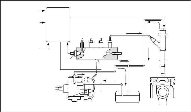
3-2. Outline of Composition and Operation A. Composition
The common rail system consists primarily of a supply pump, rail, injectors, and engine ECU.
Fuel Temperature
Vehicle Speed 
Accelerator Opening 
Intake Air Pressure
Intake Air Temperature  Engine ECU
Coolant Temperature 
Crankshaft Position 
Cylinder Recognition Signal 
Intake Airflow Rate |
|
|
|
Rail |
Pressure |
Injector |
|
Limiter |
|||
|
|||
|
|
||
Rail |
|
|
|
Pressure Sensor |
|
|
Fuel Temperature Sensor
Supply Pump |
SCV (Suction |
Fuel Tank |
|
Control Valve) |
|||
|
|||
|
|
Q000144E
B. Operation
a.Supply Pump (HP3)
The supply pump draws fuel from the fuel tank, and pumps the high pressure fuel to the rail. The quantity of fuel discharged from the supply pump controls the pressure in the rail. The SCV (Suction Control Valve) in the supply pump effects this control in accordance with commands received from the engine ECU.
b.Rail
The rail is mounted between the supply pump and the injector, and stores the high-pressure fuel.
c.Injector (G2 Type)
This injector replaces the conventional injection nozzle, and achieves optimal injection by effecting control in accordance with signals from the engine ECU. Signals from the engine ECU determine the duration and timing in which current is applied the injector. This in turn, determines the quantity, rate and timing of the fuel that is injected from the injector. QR codes noting the characteristics of each vehicle are inscribed on the injector, and this data is sent to the ECU when the engine ECU or injectors are replaced. This enables software to be adjusted to the mechanical characteristics of each injector.
d.Engine ECU
The engine ECU calculates data received from the sensors to comprehensively control the injection quantity, timing and pressure.
-5-

3-3. Fuel System and Control System A. Fuel System
This system comprises the route through which diesel fuel flows from the fuel tank via the rail to the supply pump, and is injected through the injector, as well as the route through which the fuel returns to the tank via the overflow pipe.
B. Control System
In this system, the engine ECU controls the fuel injection system in accordance with signals received from various sensors. The components of this system can be broadly divided into the following three types: (a) sensors; (b) ECU; and (c) actuators.
a.Sensors
Detect the engine and driving conditions, and convert them into electrical signals.
b.Engine ECU
Performs calculations based on the electrical signals received from the sensors, and sends them to the actuators in order to achieve optimal conditions.
c.Actuators
Operate in accordance with electrical signals received from the ECU. Injection system control is undertaken by electronically controlling the actuators. The injection quantity and timing are determined by controlling the duration and timing in which current is applied to the TWV (Two-Way Valve) in the injector. Injection pressure is determined by controlling the SCV (Suction Control Valve) in the supply pump.
|
Sensor |
|
|
|
|
|
Actuator |
|
|
Crankshaft Position Sensor NE |
Engine Speed |
|
|
|
|
|
|
|
|
|
|
|
|
Injector |
|
|
|
|
|
|
|
|
|
|
|
|
|
|
|
|
|
|
|
|
|
|
|
|
|
|
|
· Injection Quantity Control |
|
|
|
|
|
|
|
|
||
|
|
Cylinder Recognition |
|
|
|
|
· Injection Timing Control |
|
|
|
|
|
|||||
|
Cylinder Recognition Sensor G |
|
|
|
|
· Injection Pressure Control |
||
|
|
|
|
|
|
|||
|
Load |
|
Engine |
|||||
|
|
|
|
|
|
|
||
|
|
|
|
|
|
|
||
|
Accelerator Position Sensor |
|
|
|
|
|
||
|
|
|
|
ECU |
|
|
Supply Pump (SCV) |
|
|
|
|
|
|
|
|
||
|
|
|
|
|
|
|
|
|
|
|
|
|
|
|
|
· Fuel Pressure Control |
|
|
|
|
|
|
|
|
||
|
Rail Pressure Sensor |
|
|
|
|
|
|
|
|
|
|
|
|
|
|
|
|
|
|
|
|
|
|
|
EGR, Air Intake Control |
|
|
|
|
|
|
|
|
|
|
|
|
|
|
|
|
|
|
|
|
|
|
|
|
|
|
Relay, Light |
|
|
Other Sensors and Switches |
|
|
|
|
|
|
|
|
|
|
|
|
|
Q000390E |
||
|
|
|
|
|
|
|
||
|
|
|
|
|
|
|
||
|
|
|
|
|
|
|
||
-6-
4. Description of Main Components
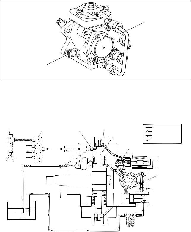
4-1. Supply Pump (HP3)
A.Outline
•The supply pump consists primarily of the pump body (camshaft (eccentric cam), ring cam, and plungers), SCV (Suction Control Valve), fuel temperature sensor, and feed pump.
SCV
Fuel Temperature Sensor
Q000570E
•The two plungers are positioned vertically on the outer ring cam for compactness.
•The engine drives the supply pump at a ratio of 1:1. The supply pump has a built-in feed pump (trochoid type), and draws the fuel from the fuel tank, sending it to the plunger chamber.
•The internal camshaft drives the two plungers, and they pressurize the fuel sent to the plunger chamber and send it to the rail. The quantity of fuel supplied to the rail is controlled by the SCV, using signals from the engine ECU. The SCV is a normally open type (the intake valve opens during de-energization).
Injector |
Rail |
Intake Valve |
Intake Pressure |
|||
Discharge Valve |
Feed Pressure |
|||||
|
|
|
|
|
|
|
|
|
Plunger |
High Pressure |
|||
|
|
|
|
|
|
Return |
|
|
|
|
|
|
Return Spring |
|
Return |
|
|
|
|
|
|
Fuel Overflow |
SCV |
||||
|
|
|||||
|
|
|
|
|
|
Regulating Valve |
|
|
|
|
|
|
Feed Pump |
|
|
|
|
|
|
|
|
|
Filter |
||||
|
|
|
||||
|
|
Camshaft |
Fuel Inlet |
|||
|
|
|
||||
Fuel Tank |
|
|
|
|
|
Intake Fuel Filter |
|
|
|
|
|
(With Priming Pump) |
|
|
|
|
|
|
|
|
|
|
|
|
|
|
Q000392E |
• The supply pump in the common rail system with DPNR has a fuel cut valve (FCV). The FCV is provided to enable manual shut-off if a fuel leak occurs in the fuel addition valve passage.
-7-
a.Supply Pump Exploded Diagram
|
SCV |
|
(Suction Control Valve) |
|
Plunger |
Pump Body |
Feed Pump |
|
|
Ring Cam |
Regulating Valve |
|
Filter |
Camshaft |
|
Plunger |
|
|
Fuel Temperature Sensor |
|
Q000393E |
|
-8- |

B. Supply Pump Internal Fuel Flow
Fuel drawn from the fuel tank passes through the route in the supply pump as illustrated, and is fed into the rail.
|
|
|
|
|
|
|
|
|
|
|
|
|
Supply Pump Interior |
|
|
|
|
|
|
|
|
||
|
|
|
|
|
|
|
|
|
|
|
|
|
|
|
|
|
|
|
|
|
|||
|
|
|
|
|
|
|
|
|
|
|
|
|
|
|
|
|
|
|
|
|
|
|
|
|
|
|
|
|
|
|
|
|
|
|
|
|
|
|
|
|
|
|
|
|
|
|
|
|
|
|
Regulating Valve |
|
|
|
|
|
|
|
|
|
|
|
|
|
|
|
|||||
|
|
|
|
|
|
|
|
|
|
|
|
|
|
||||||||||
|
|
|
|
|
|
|
|
|
|
|
|
|
|
|
|
|
|
|
|
|
|
|
|
|
|
|
|
|
|
|
|
|
|
|
|
|
|
|
|
|
|
|
|
|
|
|
|
|
|
|
|
Feed Pump |
|
|
|
|
|
SCV (Suction Control Valve) |
|
Discharge Valve |
|
|
|
Rail |
|||||||
|
|
|
|
|
|
|
|
|
|
|
|
||||||||||||
|
|
|
|
|
Overflow |
|
|
|
|
|
|
|
|
|
|
|
|
|
|
||||
|
|
|
|
|
|
|
|
Intake Valve |
|
|
Pumping Portion (Plunger) |
|
|
|
|||||||||
|
|
|
|
|
|
|
|
|
|
|
|
|
|
|
|
|
|
||||||
|
|
|
|
|
|
|
|
|
|
|
|
|
|
|
|
|
|
||||||
|
|
|
|
|
|
|
|
|
|
|
|
|
|
|
|
|
|
|
|
|
|
|
|
|
|
|
|
|
|
|
|
|
|
|
|
|
|
|
|
|
|
|
|
|
|
|
|
|
|
|
|
|
|
|
|
|
|
|
|
|
|
|
|
|
|
|
|
|
|
|
|
|
|
|
|
|
|
|
|
|
|
|
|
|
|
|
|
|
|
|
|
|
|
|
|
Fuel Tank
Q000394E
C.Construction of Supply Pump
•The eccentric cam is formed on the camshaft and is attached to the ring cam.
Ring Cam
Camshaft
Eccentric Cam
Q000395E
• As the camshaft rotates, the eccentric cam rotates eccentrically, and the ring cam moves up and down while rotating.
Eccentric Cam
Ring Cam
Camshaft
Q000396E
-9-
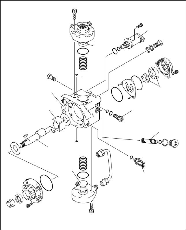
•The plunger and the suction valve are mounted on top of the ring cam. The feed pump is connected to the rear of the camshaft.
Plunger A
Ring Cam
Feed Pump
Plunger B
QD0728E
D. Supply Pump Operation
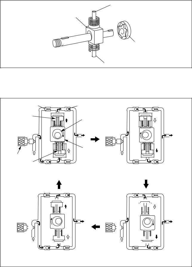
As shown in the illustration below, the rotation of the eccentric cam causes the ring cam to push Plunger A upwards. Due to the spring force, Plunger B is pulled in the opposite direction to Plunger A. As a result, Plunger B draws in fuel while Plunger A pumps it to the rail.
Suction Valve Delivery Valve
Plunger A
Eccentric Cam
Ring Cam
SCV
Plunger B
Plunger A: Finish Compression |
Plunger A: Begin IntakePlunger |
Plunger B: Finish Intake |
B: Begin Compression |
|
|
|
|
|
|
|
|
|
|
|
|
|
|
|
|
|
|
|
|
|
|
|
|
|
|
|
|
|
|
|
|
|
|
|
|
|
|
|
|
|
|
|
|
|
|
|
|
|
|
|
|
|
|
|
|
|
|
|
|
|
|
|
|
|
|
|
|
|
|
|
|
|
|
|
|
|
|
|
|
|
|
|
|
|
|
|
|
|
|
|
|
|
|
|
|
|
|
|
|
|
|
|
|
|
|
|
|
|
|
|
|
|
|
|
|
|
|
|
|
|
|
|
|
|
|
|
|
|
|
|
|
|
|
|
|
|
|
|
|
|
|
|
|
|
|
|
|
|
|
|
|
|
|
|
|
|
|
|
|
|
|
|
|
|
|
|
|
|
|
|
|
|
|
|
|
|
|
|
|
|
|
|
|
|
|
|
|
|
|
|
|
|
|
|
|
|
|
|
|
|
|
|
|
|
|
|
|
|
|
|
|
|
|
|
|
|
|
|
|
|
|
|
|
|
Plunger A: Begin Compression |
|
Plunger A: Finish Intake |
||||||||||||||||||||||||
|
Plunger B: Begin Intake |
|
Plunger B: Finish Compression |
||||||||||||||||||||||||
QD0707E
-10-
E. Description of Supply Pump Components
a.Feed Pump
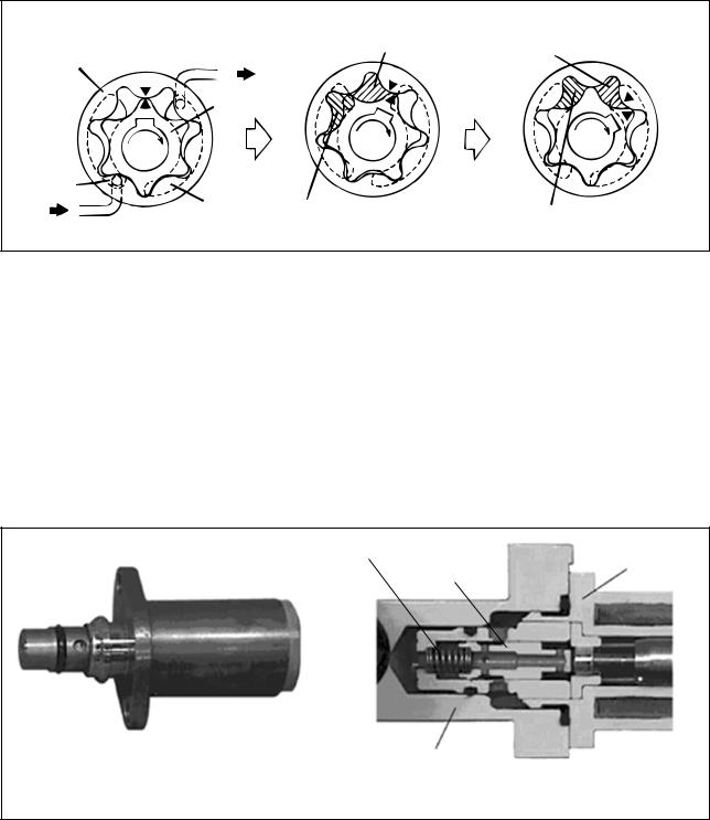
The trochoid type feed pump integrated into the supply pump, draws fuel from the fuel tank and feeds it to the two plungers via the fuel filter and the SCV (Suction Control Valve). The feed pump is driven by the camshaft. With the rotation of the inner rotor, the feed pump draws fuel from its suction port and pumps it out through the discharge port. This is done in accordance with the space that increases and decreases with the movement of the outer and inner rotors.
Quantity Decrease
To Quantity Decrease (Fuel Discharge)
Pump Chamber
Outer Rotor
Inner Rotor
Intake Port
|
Discharge |
Quantity Increase |
Quantity Increase |
|
Port |
|
|
From |
|
(Fuel Intake) |
|
|
|
||
Fuel Tank |
|
|
QD0708E |
|
|
|
b.SCV (Suction Control Valve: Normally Open Type)
•A linear solenoid type valve has been adopted. The ECU controls the duty ratio (the duration in which current is applied to the SCV), in order to control the quantity of fuel that is supplied to the high-pressure plunger.
•The supply pump drive load decreases because intake fuel quantity is controlled to achieve the target rail pressure.
•When current flows to the SCV, the internal armature moves in accordance with the duty ratio. The fuel quantity is regulated by the cylinder, which moves in connection with the armature to block the fuel passage.
•With the SCV OFF, the return spring pushes the cylinder, completely opening the fuel passage and supplying fuel to the plungers. (Full quantity intake => full quantity discharge.)
•When the SCV is ON, the return spring contracts and closes the fuel passage.
•By turning the SCV ON/OFF, fuel is supplied in an amount corresponding to the drive duty ratio and then discharged by the plungers.
Return Spring
SCV
Cylinder
Pump Body
External View |
Cross-Section |
Q000050E
-11-
Loading...