

Page 1

HINO 300 SERIES
Body Mounting Manual
TRUCK CHASSIS
TRUCK CHASSIS
XZU
XKU
(Hybrid vehicle)
&
MODEL
SERIES
KK-XZU215C
Page 2
KK-XZU215C
No part of this manual may be reproduced or transmitted in any form without the
express written permission of Hino Motors, Ltd.
© 2010, All rights reserved. Printed in Japan.
PRODUCT PLANNING DIVISION
3-1-1, HINO-DAI, HINO-SHI, TOKYO, 191-8660 JAPAN
Telephone : 042-586-5249
Facsimile : 042-586-5868
2010 - 02
Page 3

KK-XZU215C
We have published the new revised edition of Body Mounting Manual with
the following changes.
Consequently, please discard the current Body Mounting Manual
CD-ROM NO.KK-XZU215B, and use the new CD-ROM NO.KK-XZU215C
from now on.
CONTENTS OF CHANGES
The information about XKU417L-HKFQB3 (Hybrid vehicle) has been added.
RECORD OF CHANGES
Page 4
KK-XZU215C
WARNING
Request for alteration to make when reading MODEL NAME.
• The MODEL NAME in this manual of BODY MOUNTING MANUAL is
described according to the “PRODUCTION CODE” name.
• When making use of the BODY MOUNTING MANUAL, use the MODEL
NAME after replacing it in accordance with the following table.
(MODEL) (PRODUCTION CODE)
HINO 3414
XZU307L-HKMLB3
XZU307L-HKMMB3
XZU347L-HKMMB3
XZU407L-HKMMD3
XZU407L-HKMQD3
XZU417L-HKMMD3
XZU407L-HKFQD3
XZU417L-HKFQD3
XZU427L-HKFQD3
XZU407L-HKFRD3
XZU417L-HKFRD3
XZU427L-HKFRD3
HINO 3714
XKU417L-HKFQB3
AUSXZU201 00T001
HINO 3614
HINO 3616
HINO 3716
HINO 3816
Page 5

- 1 -
KK-XZU215C
Purpose
This manual is provided the Body and Equipment
Manufacturers, including inter-mediate and/or final stage
manufacturers (hereinafter collectively referred to as Body and
Equipment Manufacturers), to provide :
(1) Technical instructions for Hino truck chassis with cab for
modification and mounting of bodies.
(2) An aid to Body and Equipment Manufacturers for producing
safe vehicles under their own discretion and responsibility.
(3) Other general advice for installation, modification or
alteration.
When Body and Equipment Manufacturers install any body
or other equipment or device on Hino truck chassis with
cab (hereinafter collectively referred to as Hino Chassis), or
modify or alter a Hino Chassis.
Content
This manual contains chassis specifications and instructions
particular to model 300 series with US-04 emission control in
the Hino light duty trucks.
Important
This instruction manual must be used in combination
with the Common Manual, No. KC-AA102.
• For more information on mounting of bodies and equipments
or on chassis modifications, refer to the appropriate workshop
manuals, parts catalogs, and maintenance guides and
owner's or driver's manual.
• The information in this manual is accurate to the best of
Hino's Knowledge at the time of going to press.
Hino reserves the right to modify any and all information
without notice and without obligation.
• Should more detailed data or information be needed, please
contact authorized Hino distributor.
ABOUT THIS MANUAL
Page 6

- 2 -
KK-XZU215C
Warning
• It is the responsibility of Body and Equipment Manufacturers
or modification companies to make sure that the completed
vehicle with body and equipment, or after modification,
conforms to all applicable laws and regulations of the country
in which the vehicle is to be used (e. g. regulations on
lighting, tilt, overall size, axle load, external noise control etc.)
• This manual does not guarantee the safety of a Hino chassis
once a body or equipment has been mounted or modification
has been made by a Body and Equipment Manufacturers or a
modification company.
• This manual does not affect that ultimate responsibility for the
manufacture and mounting of the body, installation,
modification or alteration on Hino Chassis devolves upon the
Body and Equipment Manufacturer.
• Each individual Body and Equipment Manufacturer has the
sole responsibility for the design, functions, materials and
work concerning the body and equipment.
• Hino Motors, Ltd. does not assume any liability whatsoever
for any injury to persons or damage to property caused as a
result of the utilization of this manual.
ABOUT THIS MANUAL
Page 7

KK-XZU215C
1. VEHICLE SUMMARY
2. GENERAL PRECAUTIONS
3. CHASSIS MASS & FRAME SECTION MODULUS
4. SPRING & REAR AXLE
5. PTO AND CONTROL
6. ELECTRICAL SYSTEMS
7. PAINTING
8. CHASSIS DRAWINGS
9. CHASSIS FRAME DRAWINGS
10. MOUNTING OF CHASSIS EQUIPMENT
CONTENTS
Page 8

KK-XZU215C
1. VEHICLE SUMMARY
PRODUCTION CODE・・・・・・・・・・・・・・・・・・・・・・・・・・・・・・・・・・・・・・・・・・ 1 - 1
IDENTIFICATION NUMBER
・・・・・・・・・・・・・・・・・・・・・・・・・・・・・・・・・・・・ 1 - 2
CHASSIS SPECIFICATIONS
・・・・・・・・・・・・・・・・・・・・・・・・・・・・・・・・・・・・ 1 - 3
Page 9
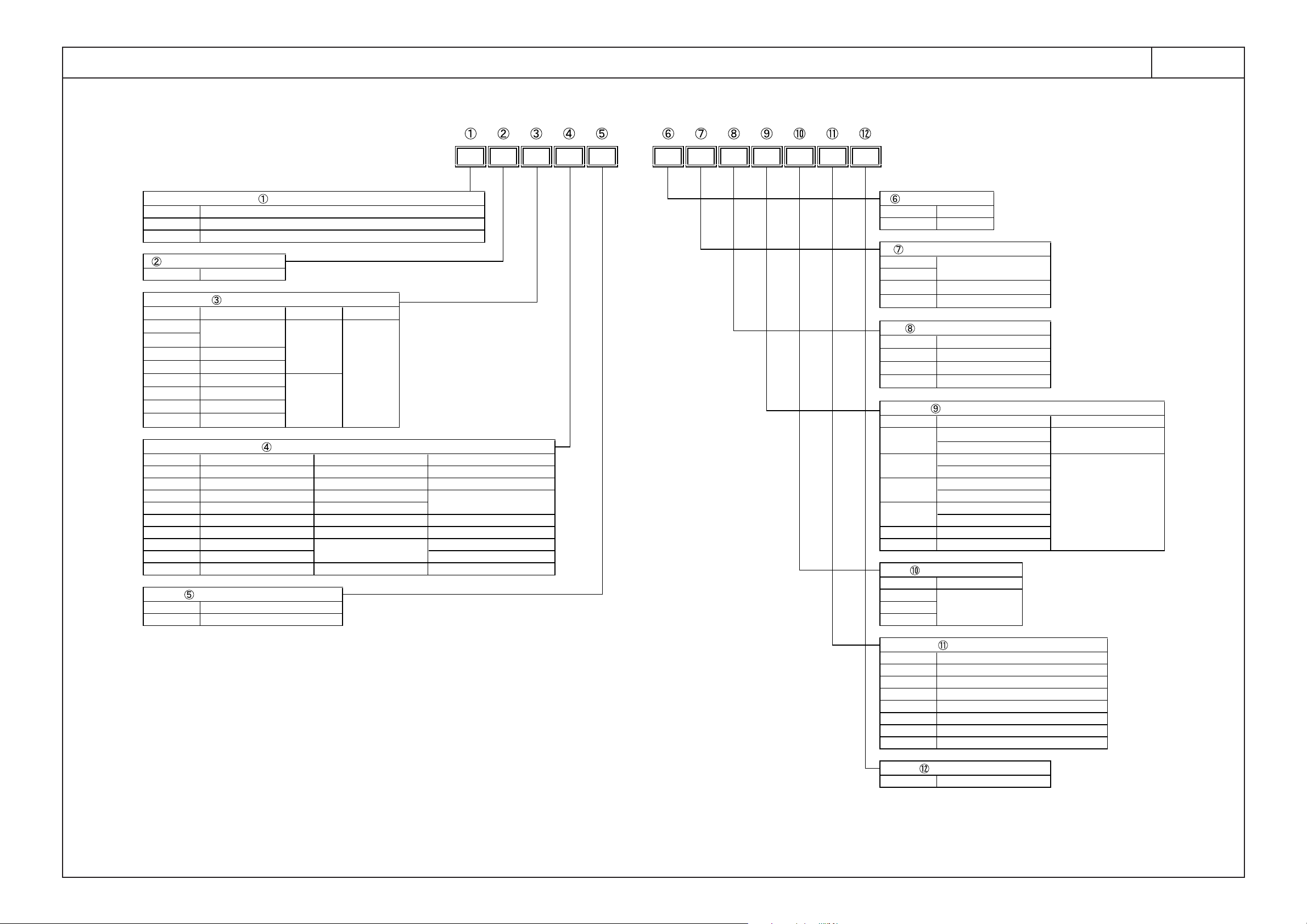
PRODUCTION CODE
1. VEHICLE SUMMARY
1 - 1
KK-XZU215C
XZ U 41 4 L - H K F R D W 3
AUSXZU201 01T001
DOUBLE
CODE
L
M
Q
R
S
7.5
6.5
4.495(FOR AUS.)
3870
4200
M
P
T
5 SPEEDS (MECH.)
4 SPEEDS (AUTO.)
6 SPEEDS (AUTO.)
M
DUMP
TRANSMISSION CODE
F
6 SPEEDS (MECH.)
BODY DECK HEIGHT CODE
B
K
Q
HIGH FLOOR
LOW FLOOR
300 SERIES
CAB DRIVEWHEEL BASE
2800
3400
L
R
LEFT HAND DRIVE
RIGHT HAND DRIVE
CHASSIS TYPE CODE
41
MODEL SERIES CODE
CODE
30
32
4 X 2
NARROW
WIDE
2810
3430
CAB TYPE CODE
HSINGLE
DOUBLEQ
42
43
5.5
4.495(FOR AUS.)
GVMR (ton)
GVMR AND REAR TIRE TYPE CODE
4.8-5.1
4.495(FOR AUS.)
REAR TIRE TYPE
SINGLE
4.495(FOR AUS.)
8.0
8.5
ENGINE CODE
T
NA
W/TURBO
DESTINATION CODE
NIL
S
A
B
D
D
N
Q
R
T
V
W
EXPORT STANDARD
INDONESIA
SOUTH AFRICA
AUSTRALIA & NEW ZEALAND
TAIWAN
THAI
GCC
EURO
SHIPPING CODE
CAB WITH CHASSIS3
34
40
U
VEHICLE MODEL CODE
2525
33
XZ
XK
N04C-TR/TS/TT, N04C-TP/TW, N04C-TU/TV
ENGINE TYPE CODE
N04C-TN/TU (N04C-H1)
W W04D, W04D-TM, W04D-TN
6
EMISSION CONTROL
EURO-1/2
-
EURO-1/2
EURO-3
-
-
EURO-4
3
4
5
ENGINE AND SUSPENSION CODE
CODE
0
1
2
RIGID
INDEPENDENT
8
ENGINE
W04D
-
W04D-TM/TN
N04C-TR/TS/TT
-
N04C-TP/TW
FRONT SUSPENSION
RIGID
-
-
RIGID
RIGID
D
US04
N04C-TU
N04C-TN
7 RIGIN04C-TU/TV
Page 10
1 - 2
KK-XZU215C
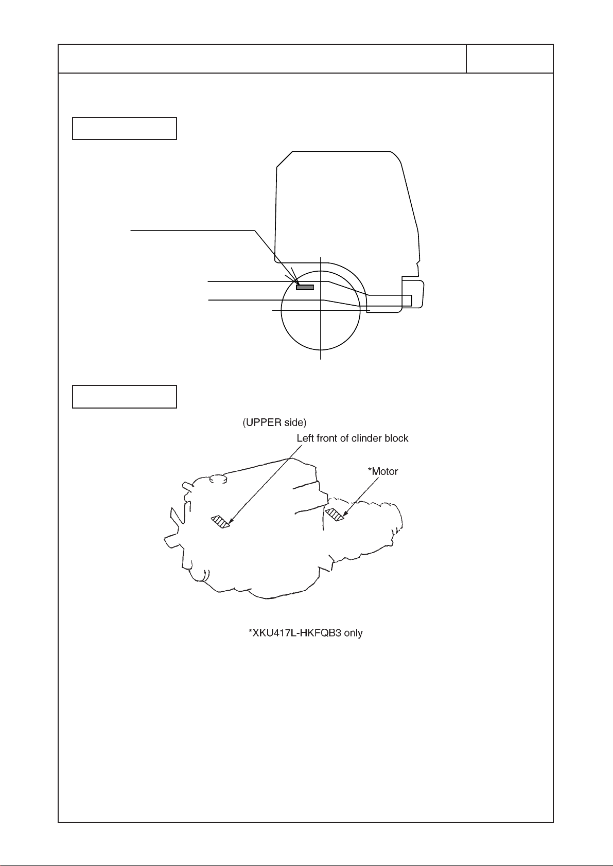
IDENTIFICATION NUMBER
Located at the side
member of chassis frame.
FXZ1 C No
CHASSIS
ENGINE
Page 11
CHASSIS SPECIFICATIONS
1 - 3
KK-XZU215C
[NOTE]
• Permissible axle capacity and GVM or GCM capacity listed above table must not be exceeded.
• The front axle load must exceed 30% of the gross vehicle mass under full loaded condition.
• The height of center of gravity from ground on the unloaded vehicle with body mounted should be 0.82m (XZU307L-HKMLB3 only) or less.
• The height of center of gravity from ground on the unloaded vehicle with body mounted should be 0.88m (STANDARD CAB SERIES), 1.00m (WIDE CAB SERIES) or less.
• Weight distribution on the left and right wheels should be balanced.
• Both front axle and rear axle loads must not exceed the permissible load based on the tire load capacity according to the tire standards in your country.
• The dimension of tires to be mentioned in above chassis specification shows design figure according to JATMA or ETRTO standard.
Cab type
Chassis model
Item
Drive system (number of wheels) 4x2 (4) 4x2 (6) 4x2 (6) 4x2 (6) 4x2 (6) 4x2 (6) 4x2 (6) 4x2 (6) 4x2 (6) 4x2 (6) 4x2 (6) 4x2 (6) 4x2 (6)
Wheel base (mm) 2525 2525 3400 2810 2810 2810 2810 3430 3430 3430 3870 3870 3430
Tread
Max. GVM Rating (kg) 4300 5500 5500 5500 5500 6500 7500 5500 6500 7500 6500 7500 6500
Capacity (kg) Rear 4400 4400 4400 4400 5100 5100 5500 4400 5100 5500 5100 5500 5100
(On std. Spec.) Front 2300 2300 2300 2300 2800 2800 3200 2300 2800 3200 2800 3200 2430
Chassis mass (kg) Refer to page 3-1 Refer to page 3-1 Refer to page 3-1 Refer to page 3-1 Refer to page 3-1 Refer to page 3-1 Refer to page 3-1 Refer to page 3-1 Refer to page 3-1 Refer to page 3-1 Refer to page 3-1 Refer to page 3-1 Refer to page 3-1
Model N04C-TU N04C-TU N04C-TU N04C-TV N04C-TV N04C-TV N04C-TV N04C-TV N04C-TV N04C-TV N04C-TV N04C-TV N04C-UK
Max. Out put JIS gross 103{140}/2700 103{140}/2700 103{140}/2700 114{155}/2700 114{155}/2700 114{155}/2700 114{155}/2700 114{155}/2700 114{155}/2700 114{155}/2700 114{155}/2700 114{155}/2700 103{140}/3000
Engine (kW{PS}/rpm) ISO net 100{136}/2700 100{136}/2700 100{136}/2700 110{150}/2700 110{150}/2700 110{150}/2700 110{150}/2700 110{150}/2700 110{150}/2700 110{150}/2700 110{150}/2700 110{150}/2700 100{136}/3000
Max. Torque JIS gross 364{37.1}/1800 364{37.1}/1800 364{37.1}/1800 404{41.2}/1800 404{41.2}/1800 404{41.2}/1800 404{41.2}/1800 404{41.2}/1800 404{41.2}/1800 404{41.2}/1800 404{41.2}/1800 404{41.2}/1800 359{36.6}/1600
(N·m{kgf·m}/rpm) ISO net 358{36.5}/1800 358{36.5}/1800 358{36.5}/1800 397{40.5}/1800 397{40.5}/1800 397{40.5}/1800 397{40.5}/1800 397{40.5}/1800 397{40.5}/1800 397{40.5}/1800 397{40.5}/1800 397{40.5}/1800 353{36.05}/1600
Emission US04 US04 US04 US04 US04 US04 US04 US04 US04 US04 US04 US04 US04
Height of gravity from ground (m) Refer to page 3-1 Refer to page 3-1 Refer to page 3-1 Refer to page 3-1 Refer to page 3-1 Refer to page 3-1 Refer to page 3-1 Refer to page 3-1 Refer to page 3-1 Refer to page 3-1 Refer to page 3-1 Refer to page 3-1 Refer to page 3-1
Tire and disc
Fuel tank (L) 70 70 100 100 100 100 100 100 100 100 100 100 100
Battery 12-216{60}x2 12-216{60}x2 12-216{60}x2 12-216{60}x2 12-216{60}x2 12-216{60}x2 12-216{60}x2 12-216{60}x2 12-216{60}x2 12-216{60}x2 12-216{60}x2 12-216{60}x2 12-288{80}x2
Alternator V - A 24-60 24-60 24-60 24-60 24-60 24-60 24-60 24-60 24-60 24-60 24-60 24-60 24-80
Body width (See notes.) (mm)
(mm)
Front 1400 1400 1400 1660 1665 1665 1655 1660 1665 1655 1655 1655 1655
Rear 1350 1435 1435 1480 1520 1520 1520 1480 1520 1520 1520 1520 1520
Front 2600 2600 2600 2600 3100 3100 3100 2600 3100 3100 3100 3100 3100
Axle
Tire
Disc
V - kC {Ah} - No.
Rear 2300 4360 4360 4360 5280 5280 6200 4360 5280 6200 5280 6200 4480
Front 205/75R16C 205/75R16C 205/75R16C 205/75R16C 215/85R16 215/85R16 215/75R17.5 205/75R16C 215/85R16 215/75R17.5 215/85R16 215/75R17.5 215/85R16
Tire
Rear 205/75R16C 205/75R16C 205/75R16C 205/75R16C 215/85R16 215/85R16 215/75R17.5 205/75R16C 215/85R16 215/75R17.5 215/85R16 215/75R17.5 215/85R16
Front 16x5.5K-115mm 16x5.5K-115mm 16x5.5K-115mm 16x5.5K-115mm 16x5.5K-122mm 16x5.5K-122mm 17.5x6.00-127mm 16x5.5K-115mm 16x5.5K-122mm 17.5x6.00-127mm 16x5.5K-122mm 17.5x6.00-127mm 16x5.5K-122mm
Rear 16x5.5K-115mm 16x5.5K-115mm 16x5.5K-115mm 16x5.5K-115mm 16x5.5K-122mm 16x5.5K-122mm 17.5x6.00-127mm 16x5.5K-115mm 16x5.5K-122mm 17.5x6.00-127mm 16x5.5K-122mm 17.5x6.00-127mm 16x5.5K-122mm
XZU307L-HKMLB3 XZU307L-HKMMB3 XZU347L-HKMMB3 XZU407L-HKMMD3 XZU417L-HKMMD3 XZU427L-HKFRD3XZU407L-HKFQD3
STANDARD CAB SERIES
XZU407L-HKMQD3 XZU407L-HKFRD3
1896
WIDE CAB SERIES
2095
XZU427L-HKFQD3XZU417L-HKFQD3 XZU417L-HKFRD3
XKU417L-HKFQB3
AUSXZU201 01T002
Page 12

KK-XZU215C
2. GENERAL PRECAUTIONS
FIRE SHIELD ・・・・・・・・・・・・・・・・・・・・・・・・・・・・・・・・・・・・・・・・・・・・・・・・ 2 - 1
CLEARANCE BETWEEN CAB AND REAR BODY OR
・・・・・・・・・・・・ 2 - 2
EQUIPMENT
RECOMMENDED POSITIONS OF U-BOLTS
・・・・・・・・・・・・・・・・・・・・ 2 - 3
RECOMMENDED POSITIONS OF REAR FENDERS AND
・・・・・・・・・・ 2 - 4
MUDGUARDS
ELECTRIC WELDING WORK
・・・・・・・・・・・・・・・・・・・・・・・・・・・・・・・・・・ 2 - 5
NOTES ON ADDITIONAL WIRING IN THE ENGINE
・・・・・・・・・・・・・・ 2 - 6
COMPARTMENT
NOTES ON ENGINE CONTROL, BRAKE ABS SYSTEM
・・・・・・・・・・ 2 - 7
COMPUTERS AND DC-DC CONVERTER
HANDLING OF PARTS FOR MEETING THE EXTERNAL
・・・・・・・・・・ 2 - 8
NOISE CONTROL REGULATION
PRECAUTION ON BODY MOUNTING WORK
・・・・・・・・・・・・・・・・・・・・ 2 - 9
THE NOISE MEASURES OF THE AM RADIO
・・・・・・・・・・・・・・・・・・・・ 2 - 10
Peculiar to XKU417L-HKFQB3
*
*
*
Page 13
2 - 1
2. GENERAL PRECAUTIONS
FIRE SHIELD
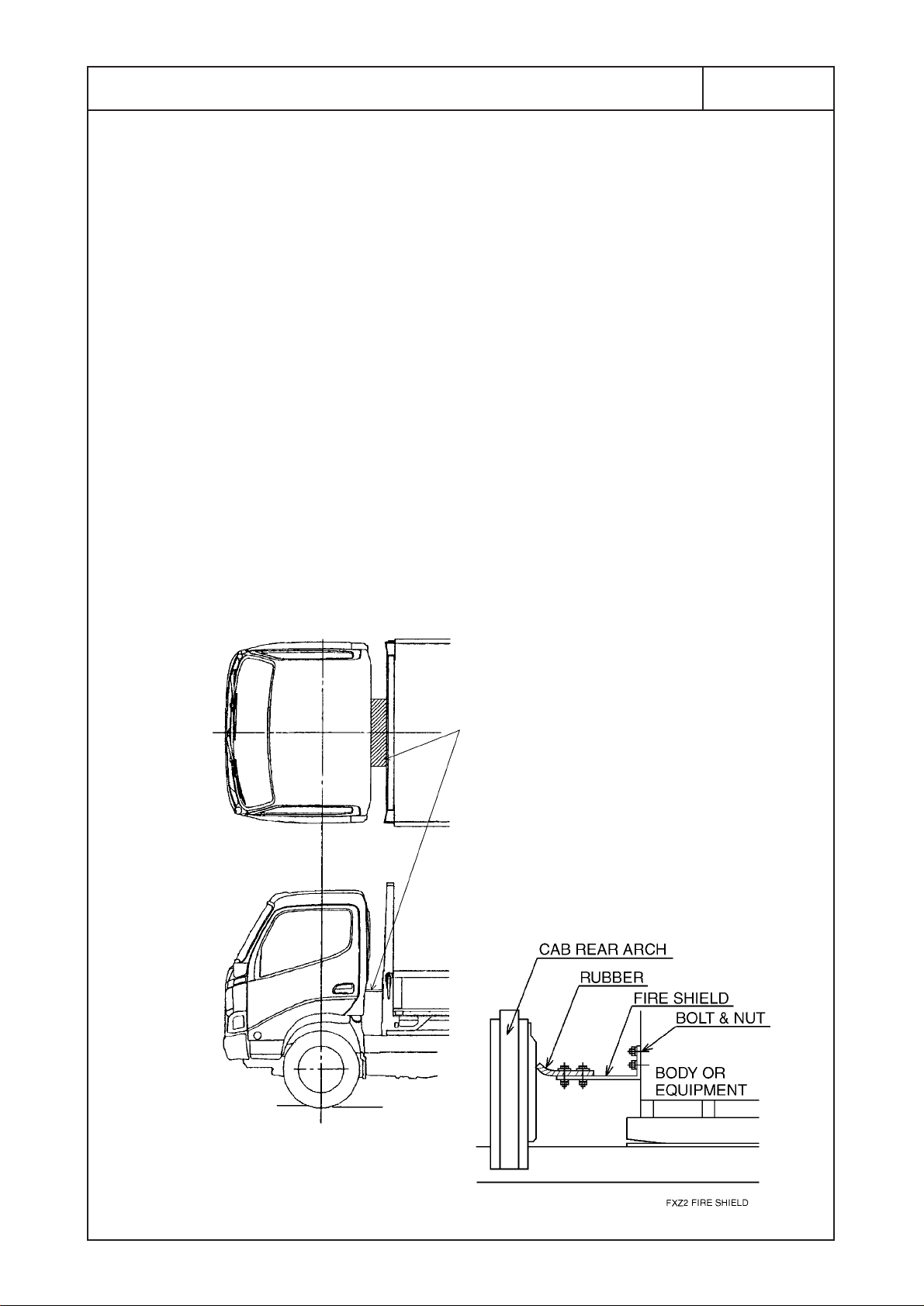
1) Gap Between Cab Rear End and Body
When a flat bed or similar body has been mounted, a fire
shield should be fitted across the gap between the cab rear
end and the front end of the load platform frame to prevent fires
that may be caused by flammable materials
falling off from the load platform onto the exhaust pipe (see
figure below).
A fire shield is not necessary if the body is fitted with a sheet
carrier attached directly to the top of the front guard.
A fire shield is also not necessary for such bodies as dump
trucks, mixers, tankers, and aluminum vans, where there is no
danger of flammable materials falling off.
[NOTE] When you mount the fire shield, use bolts, etc., that
can be taken out to allow for replacement of the
chassis parts which are located at the rear part of cab.
KK-XZU215C
• For approximately 50 mm from the front
edge of fire shield (the cab side), use
rubber to match the shape of the fire
shield to that of the cab rear end such
as rear arch cover.
• You may also install the fire shield so
that it covers only the exhaust pipe.
Page 14
2 - 2 - 1
KK-XZU215C
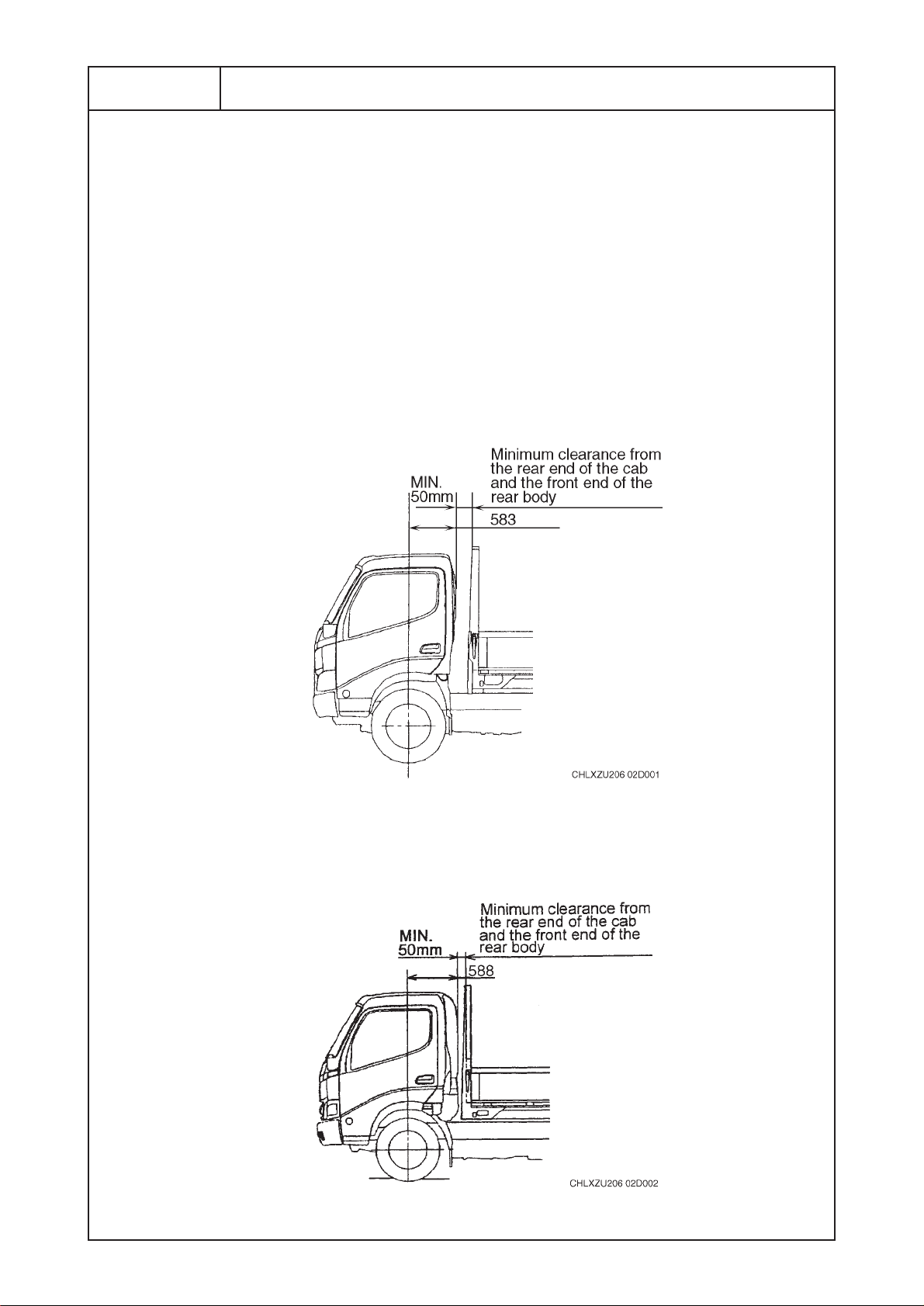
CLEARANCE BETWEEN CAB AND REAR BODY OR EQUIPMENT
The rear part of the cab contains the cab lock mechanism or
stack exhaust pipe as well as the engine cylinder block.
When mounting the rear body or equipment, allow at least the
minimum clearance between the rear end of the cab or stack
exhaust pipe and the front end of the rear body, to avoid
obstructing the operation of cab lock mechanism or avoiding
fire.
1) Minimum Clearance with Cab Rear End
(1) STANDARD CAB series
Unit : mm
(2) WIDE CAB series
Page 15
2 - 2 - 2
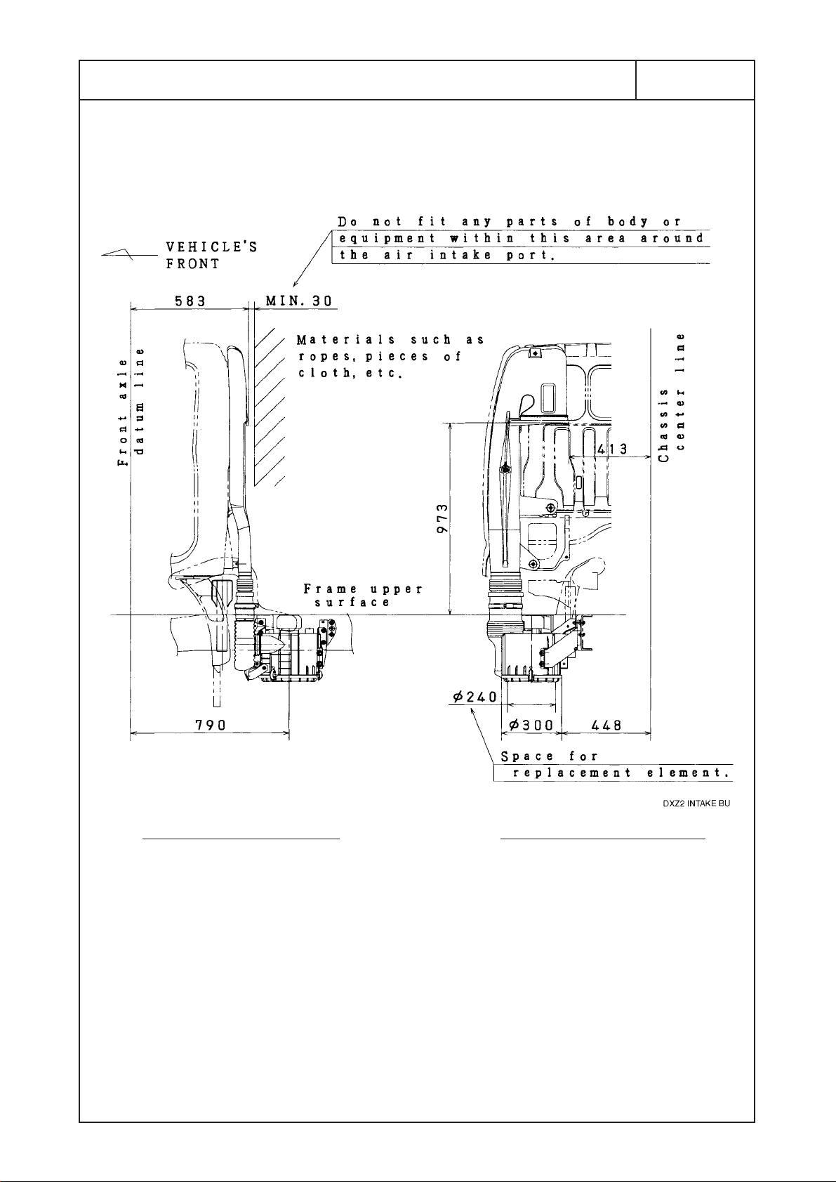
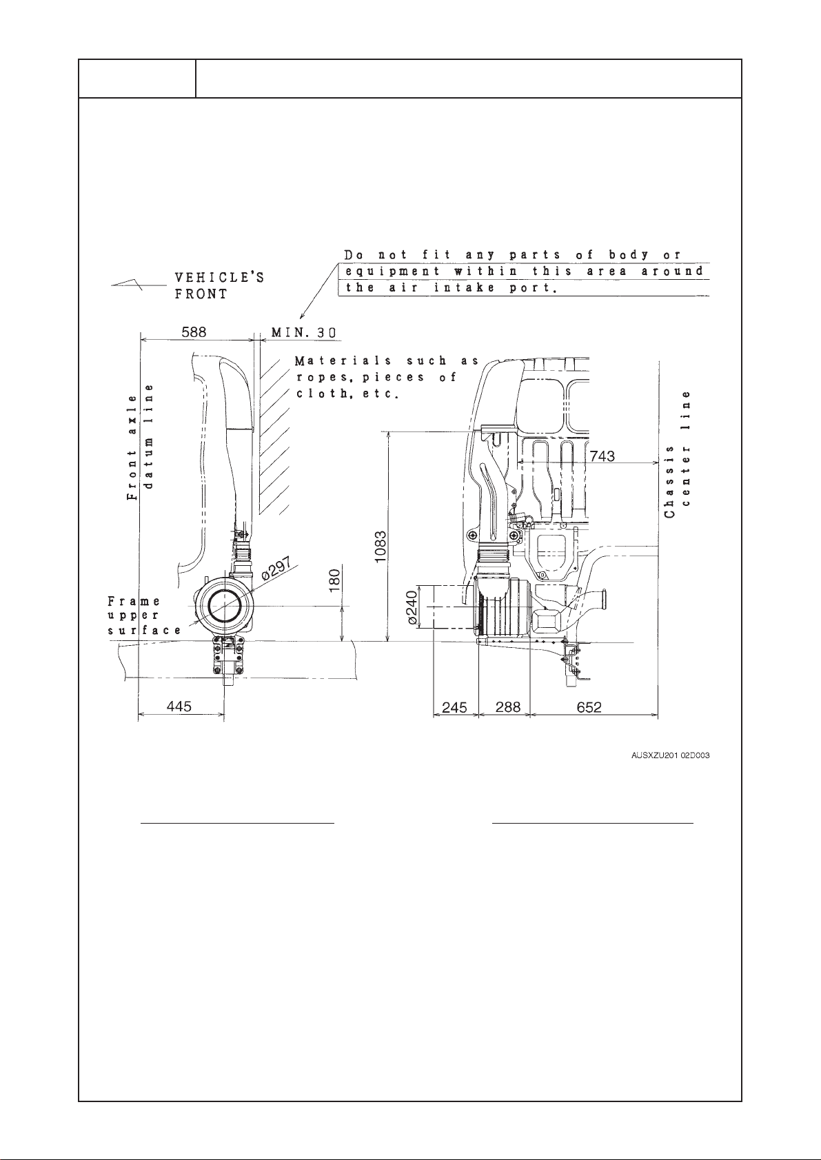
2) Measurement of the Engine Air Intake Port
• STANDARD CAB series Unit : mm
SIDE VIEW ( LEFT SIDE )
REAR VIEW ( LEFT SIDE )
KK-XZU215C
Page 16
2 - 2 - 3
KK-XZU215C
• WIDE CAB series Unit : mm
SIDE VIEW ( LEFT SIDE )
REAR VIEW ( LEFT SIDE )
Caution
The blocking of the smooth flow of air into the air intake pipe caused by
any materials such as ropes, pieces of cloth, etc. leads to the increase
of exhaust temperature if driven long intervals. The increase in exhaust
temperature is caused by the decreased efficiency in the combustion
process, as the proportion of air in the combustion chamber is also
decreased by the above mentioned factor. This situation will lead to
major malfunctions such as the cracking of the exhaust manifold and
the breaking down of the turbocharger. To avoid such malfunctions,
please keep the air intake pipe free from any blocking materials at all
times.
Page 17
2 - 2 - 4
KK-XZU215C
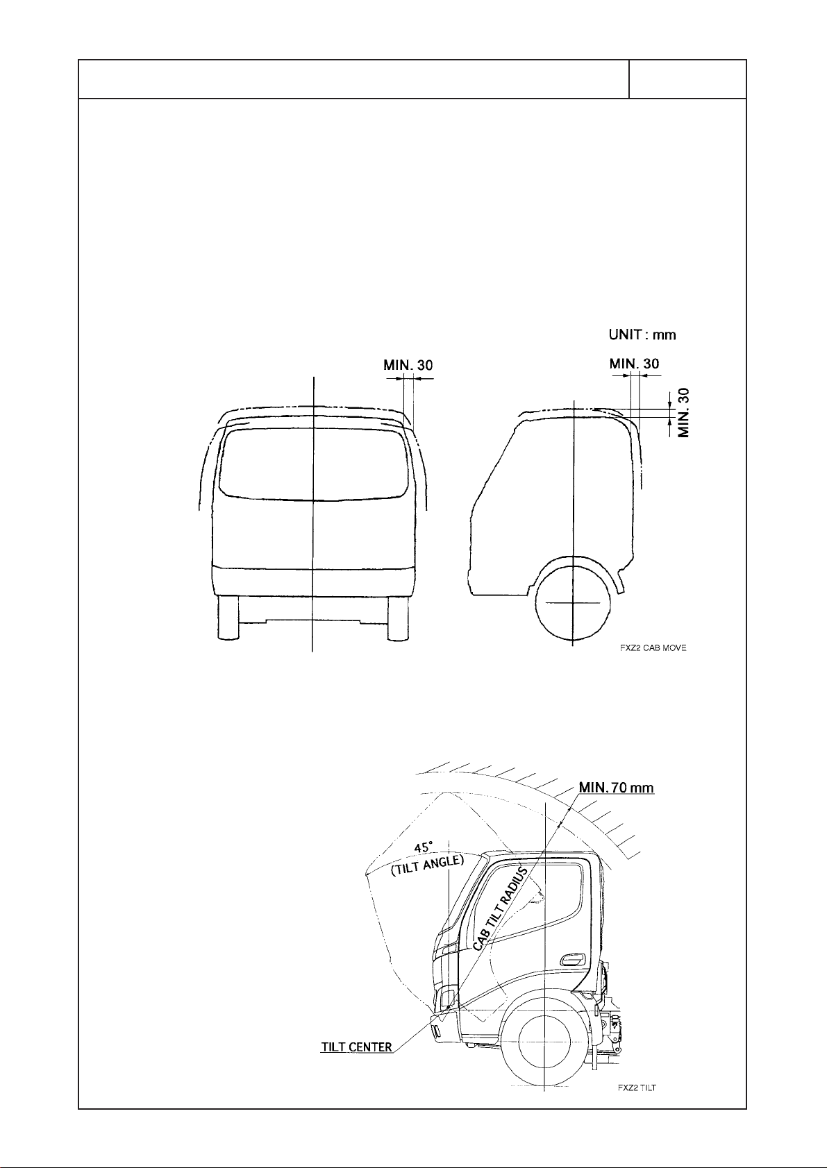
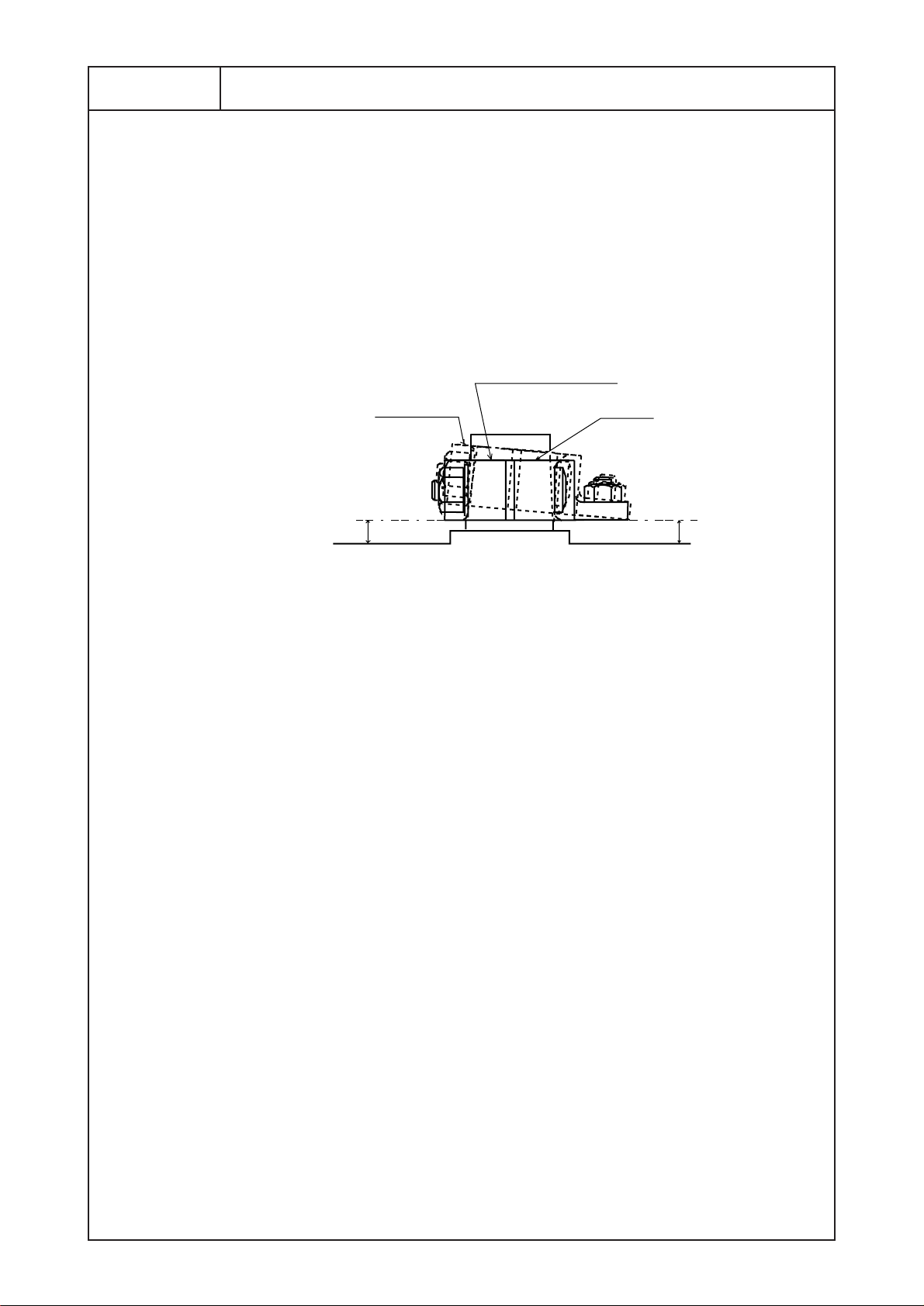
3) Minimum Clearance with Cab Outer Shell
• Even under normal driving conditions, when the cab is not
tilted, it moves back and front, right and left, and up and
down. The body or equipment must not interfere with cab
movement.
• Allow at least 30 mm clearance between the cab and rear
body or equipment.
• When cab tilt, allow at least 70 mm clearance the cab and
rear body or equipment. For details of cab tilt dimensions, see
the Body Mounting Manual for the respective model series.
Page 18
2 - 2 - 5
KK-XZU215C
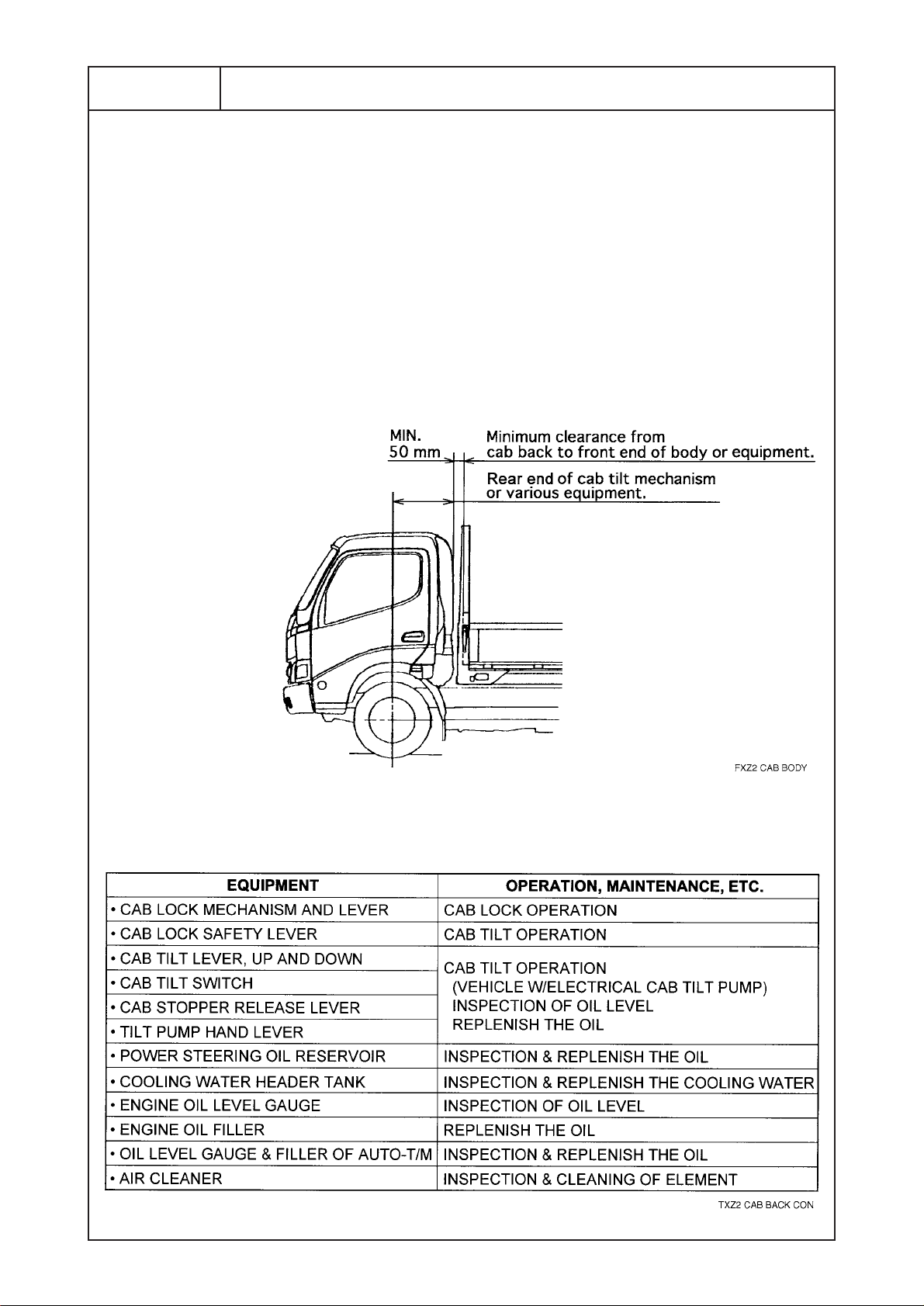
4) Contained Equipment of Cab Rear End
The rear part of the cab contains the cab lock mechanism and
the tilt mechanism, as well as the engine cylinder block or
other various equipment.
When mounting the body or equipment, allow at least the
minimum clearance between the rear end of the cab and the
front end of the rear body or equipment, to avoid obstructing
the operation and maintenance of these mechanisms or
various equipment.
For details of cab dimensions, see chassis drawings.
[ EXAMPLE ]
Page 19
2 - 3
KK-XZU215C
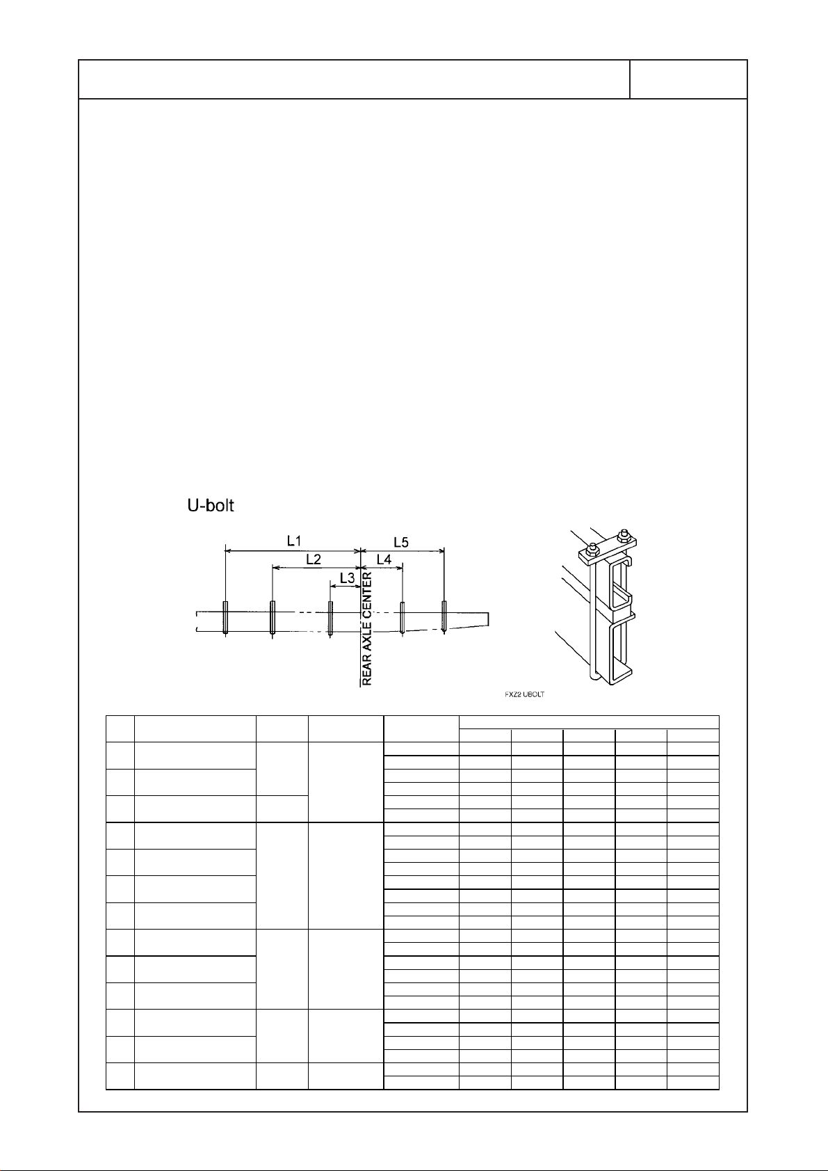
RECOMMENDED POSITIONS OF U-BOLTS
[NOTES]
(1) The details of setting positions of the U-bolt are shown in
following figure.
Fasten the U-bolt as much as possible to the positions
described in following figure when a body or equipment are
going to be mounted to the chassis.
(2) If the U-bolt positions are to be altered according to the
constructions or kinds of the body, determine the place where
U-bolt to be fastened after carefully studies the condition of the
chassis to prevent contact with the brake pipes, hoses and
harness wires.
(3) The position of U-bolts at forward of No.3 crossmember
should be observed according to the figure shown next page
due to structure and layout of each component parts of the
chassis.
(mm)
(mm)
W/B CAB
1
XZU307L-HKMLB3
2
XZU307L-HKMMB3
3
XZU347L-HKMMB3
4
XZU407L-HKMMD3
5
XZU407L-HKMQD3
6 XZU407L-HKFQD3
7
XZU407L-HKFRD3
8
XZU417L-HKMMD3
9
XZU417L-HKFQD3
10
XZU417L-HKFRD3
11 XZU427L-HKFQD3
12 XZU427L-HKFRD3
13 XKU417L-HKFQB3 3430 WIDE
2525
3400
2810
3430
3870
TYPE L1 L2 L3 L4 L5
STD
WIDE
WIDE
WIDE
POSITIONNo. MODEL
RH 1595 – 264 – 1000
LH 1495 – 264 – 1035
RH 1595 – 264 – 1000
LH 1495 – 264 – 1035
RH 2470 935 – – 1410
LH 2362 935 – – 1410
RH 1780 – 236 – 950
LH 1780 – 236 – 950
RH 1780 – 236 – 950
LH 1780 – 236 – 950
RH 1780 – 236 – 950
LH 1780 – 236 – 950
RH 1780 – 236 – 950
LH 1780 – 236 – 950
RH 2400 – 233 – 1360
LH 2400 – 233 – 1360
RH 2400 – 233 – 1360
LH 2400 – 233 – 1360
RH 2400 – 233 – 1360
LH 2400 – 233 – 1360
RH 2820 1120 – – 1560
LH 2820 900 – – 1560
RH 2820 1120 – – 1560
LH 2820 900 – – 1560
RH 2400 – 233 – 1360
LH 2400 – 233 – 1360
DIMENSION
AUSXZU201 02T002
Page 20
2 - 4 - 1
KK-XZU215C
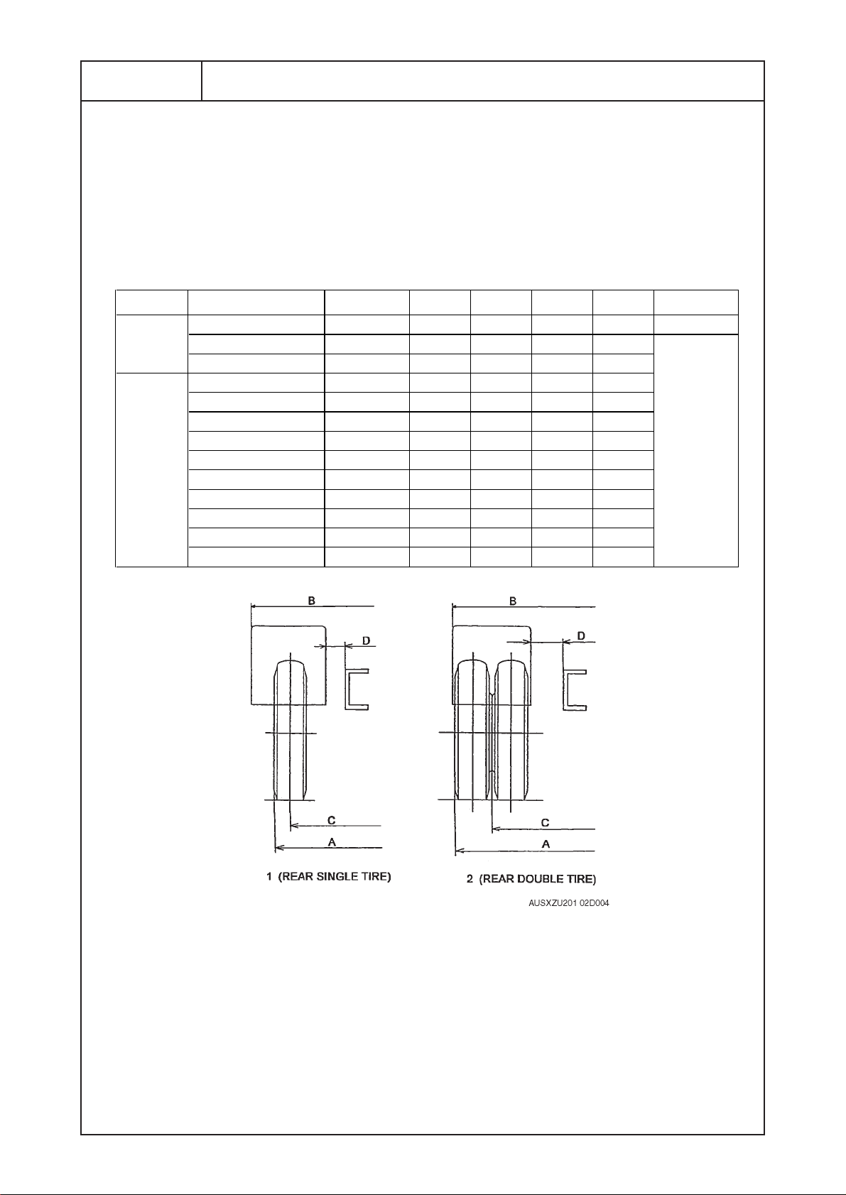
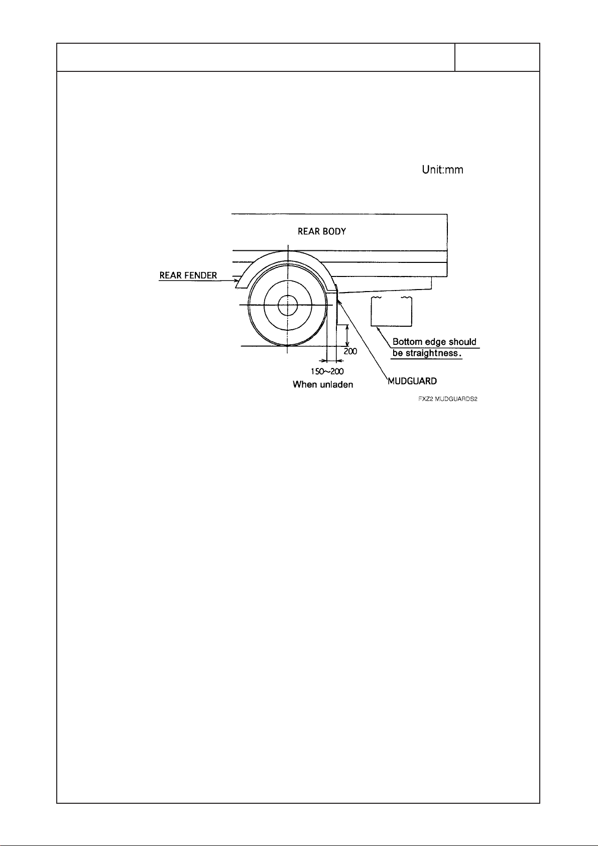
RECOMMEND POSITIONS OF REAR FENDERS AND MUDGUARDS
When mounting rear fenders and mudguards, determine
required clearances with reference to the following table and
figures of "MAXIMUM VERTICAL DEFLECTION OF REAR
WHEEL" in 4-2.
1) Rear Fender Unit : mm
[NOTE]
The dimension of tire to be mentioned in above table shows design figure according
to JATMA or ETRTO standard.
CAB TYPE MODEL TIRE SIZE A B C D REAR TIRE
XZU307L-HKMLB3 205/75R16C 1636 1656 1350 210 SINGLE
STD
WIDE
XZU307L-HKMMB3 205/75R16C 1876 1896 1435 137
XZU347L-HKMMB3 205/75R16C 1876 1896 1435 137
XZU407L-HKMMD3 205/75R16C 1921 1941 1480 135
XZU407L-HKMQD3 215/85R16 1986 2006 1520 142
XZU407L-HKFQD3 215/85R16 1986 2006 1520 142
XZU407L-HKFRD3 215/75R17.5 1994 2014 1520 138
XZU417L-HKMMD3 205/75R16C 1921 1941 1480 135
XZU417L-HKFQD3 215/85R16 1986 2006 1520 142
XZU417L-HKFRD3 215/75R17.5 1994 2014 1520 138
XZU427L-HKFQD3 215/85R16 1986 2006 1520 142
XZU427L-HKFRD3 215/75R17.5 1994 2014 1520 138
XKU417L-HKFQB3 215/85R16 1989 2009 1520 141
DOUBLE
AUSXZU201 02T003
Page 21
2 - 4 - 2
KK-XZU215C
2) Mudguards
Page 22
2 - 5 - 1
KK-XZU215C
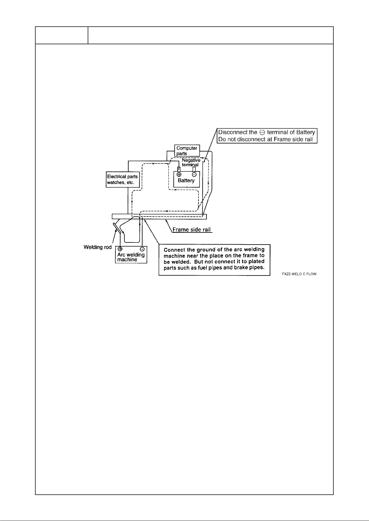
ELECTRIC WELDING WORK
Electrical components such as the alternator and tachograph
are directly connected to the battery and one end is grounded
to the chassis frame. Under these conditions, welding current
will flow back along the ground circuit if electric welding is
carried out and damage may be caused to the alternator,
tachograph, electrical components, etc.
Be sure to follow all instructions to be described to chapter 2,
2-9 PRECAUTION ON BODY MOUNTING WORK and
following precautions at performing any electric welding.
(1) procedure before welding
• Make sure to always wear the electric insulation
equipment(insulation rubber gloves .etc)while working.
•Turn the starter switch OFF.
• Pull out the SERVICE PLUG of PCU and wait more than 7
minutes.
• Disconnect the battery's negative terminal.
• Disconnect the connector of DC-DC Converter.
• Disconnect fuse of ECU of the each electronic instrument
(except DC-DC Converter).
• Dinconnect all signal circuit connectors in PCU, after taking
off the front under cover of PCU.
(See the page 2-5-3)
Peculiar to XKU417L-HKFQB3
*
*
*
*
*
Page 23
2 - 5 - 2
KK-XZU215C
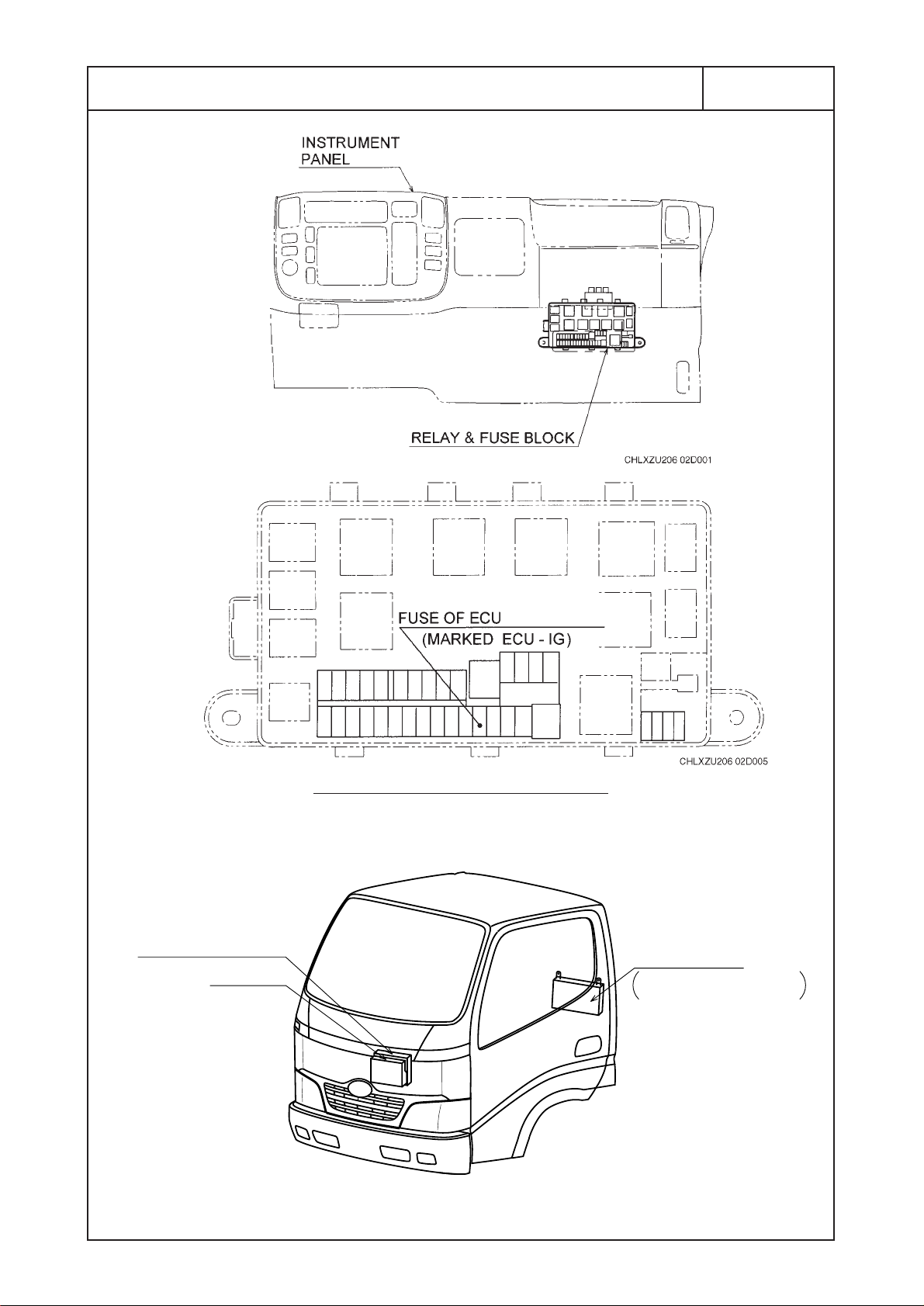
DETAILS, RELAY & FUSE BLOCK
AUSXZU201 02D006
E/G CONTROL ECU
ABS ECU
DC-DC
CONVERTER
PASSENGER
SEAT SIDE
Page 24

2 - 5 - 3
KK-XZU215C
FRONT UNDER COVER
SIGNAL CIRCUIT
CONNECTOR
PCU
WIRE HARNESS
OF SIGNAL
CIRCUIT
UP
FR
CHASSIS
CENTER
Page 25
2 - 5 - 4
KK-XZU215C
(2) Ground of the Welding Equipment
Connect the ground of the welding equipment near the place
where to be welded.
Welding to the chassis frame
• Connect the ground to the bolt (plating bolt) or chassis
frame near the place where to be welded.
• Peel off the paint where to be welded.
• Connecting the ground to the chassis spring is strictly
prohibited to prevent damage of the spring.
W
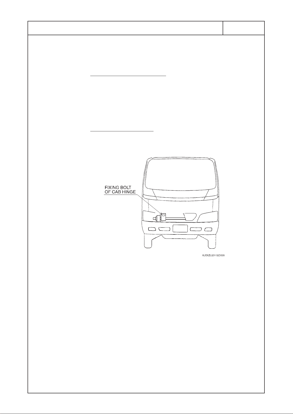
elding to the cab body
• Connect the ground to the fixing bolt of cab hinge after
dismounting the front grille or to the cab body.
(3) Other Precautions
•To protect ancillary equipment from sparks during welding,
place fire-resistant covers over the rubber hoses, wire
harness, pipes, chassis spring and tires, etc.
• Perform to weld under most suitable conditions of the
welding, and minimize the heat influence to the circumference
where to be welded, and as far as possible to keep the
welding quality.
Page 26
2 - 5 - 5
KK-XZU215C
(4) After Welding
• Make sure to connect all signal circuit connectors in PCU.
• Put back fuses as original condition.
• Make sure to connect the DC-DC Converter.
• Make sure to connect the negative terminal of the battery.
And the terminal should be horizontally setting.
• Re-paint the place where to be peeled off the paint for
grounding the welding equipment by same color.
(5) Final Inspection after Welding
• Restore each electronic instrument and equipment to its
original site.
• Install the SERVICE PLUG.
(Refer the 2-9 PRECAUTION ON BODY MOUNTING WORK)
• Inspect the operation and function of all electronic instruments
and equipments.
• Consult to each Hino sales dealer or distributor for the details
of inspection’s procedure.
Peculiar to XKU417L-HKFQB3
BATTERY
A : B = SAME HEIGHT
GOOD
NO GOOD
BA TTER Y TERMINAL
A
B
FXZ2 BATTERY
*
*
*
Page 27

2 - 6
KK-XZU215C
NOTES ON ADDITIONAL WIRING IN THE ENGINE COMPARTMENT
Since the engines in HINO trucks are covered with sound
arrest plates, the engine compartment tends to heat up.
Avoid wiring in the engine compartment if possible.
Additional wiring harness or cable should be kept away from
heated elements, and should be wired along the main harness.
Page 28
2 - 7
KK-XZU215C
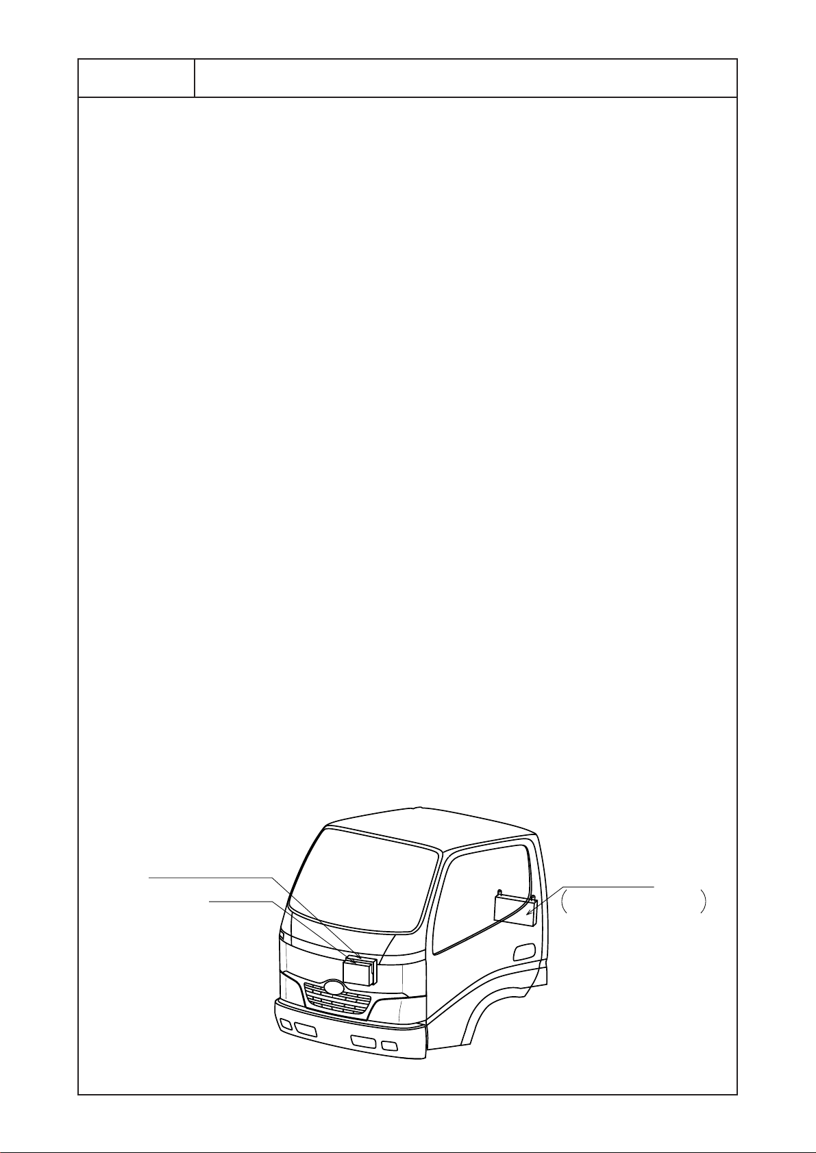
NOTES ON ENGINE CONTROL, BRAKE ABS SYSTEM
COMPUTERS AND DC-DC CONVERTER
Engine control and brake ABS computers are installed center
part, inside of the instrument panel, and DC-DC converter is
installed on right side of the cab back panel as described
following figure.
Therefore, give great care to the computer and converter when
performing any body mounting work or modification as
following points.
(1) Be sure to follow the all instruction to be described to
chapter 2, 2-5 ELECTRIC WELDING WORK and 2-9
PRECAUTION ON BODY MOUNTING WORK (XKU417LHKFQB3 only) before peforming any electric welding.
(2) Be sure to cover the computer and converter to protect the
water penetration when performing cleaning up the inside
of cab.
(3) When mounting such devices as a radiophone, a wireless
communication device, be sure to use the devices that
conforms to the electric control act and install the devices
on the places which are as far as possible from the
computers and it's harness.
Do not install any high output (over 50w) device.
Be sure to check that no abnormal electric wave or
electromagnetic wave is found, after having installed the
device, which affects on the electronic signals passing
through in computer harness.
(4) Do not alter the computer and converter, harness wire or
sensors.
AUSXZU201 02D006
E/G CONTROL ECU
ABS ECU
DC-DC
CONVERTER
PASSENGER
SEAT SIDE
Page 29

2 - 8
KK-XZU215C
HANDLING OF PARTS FOR MEETING THE EXTERNAL NOISE
CONTROL REGULATION
To comply with the external noise control regulation, parts for
external noise reduction, such as sound-insulating materials
(cover, rubber) sound-absorbing materials, muffler etc., are
equipped on the cab, the engine and the chassis. Since the
parts for external noise reduction and their fitting locations are
depending on the vehicle model, refer to the corresponding
explanatory example drawing shown in the following. To ensure
external noise reductions, following items must be observed
when mounting a superstructure.
(1) The parts for external noise reduction must not be modified
or detached, since their specifications are determined to
comply with the limiting value of the external noise
regulation. The position and/or direction of the tail pipe
must also not be changed.
(2) If the parts for external noise reduction are temporarily
detached for mounting a superstructure, handle them
carefully to prevent their deformation and/or damage, and
be sure attach them on original position after completion of
mounting the superstructure.
If the parts for external noise reduction have been
deformed and/or damaged, replace them with genuine
parts and never use rectified parts.
Page 30
2 - 9 - 1
KK-XZU215C
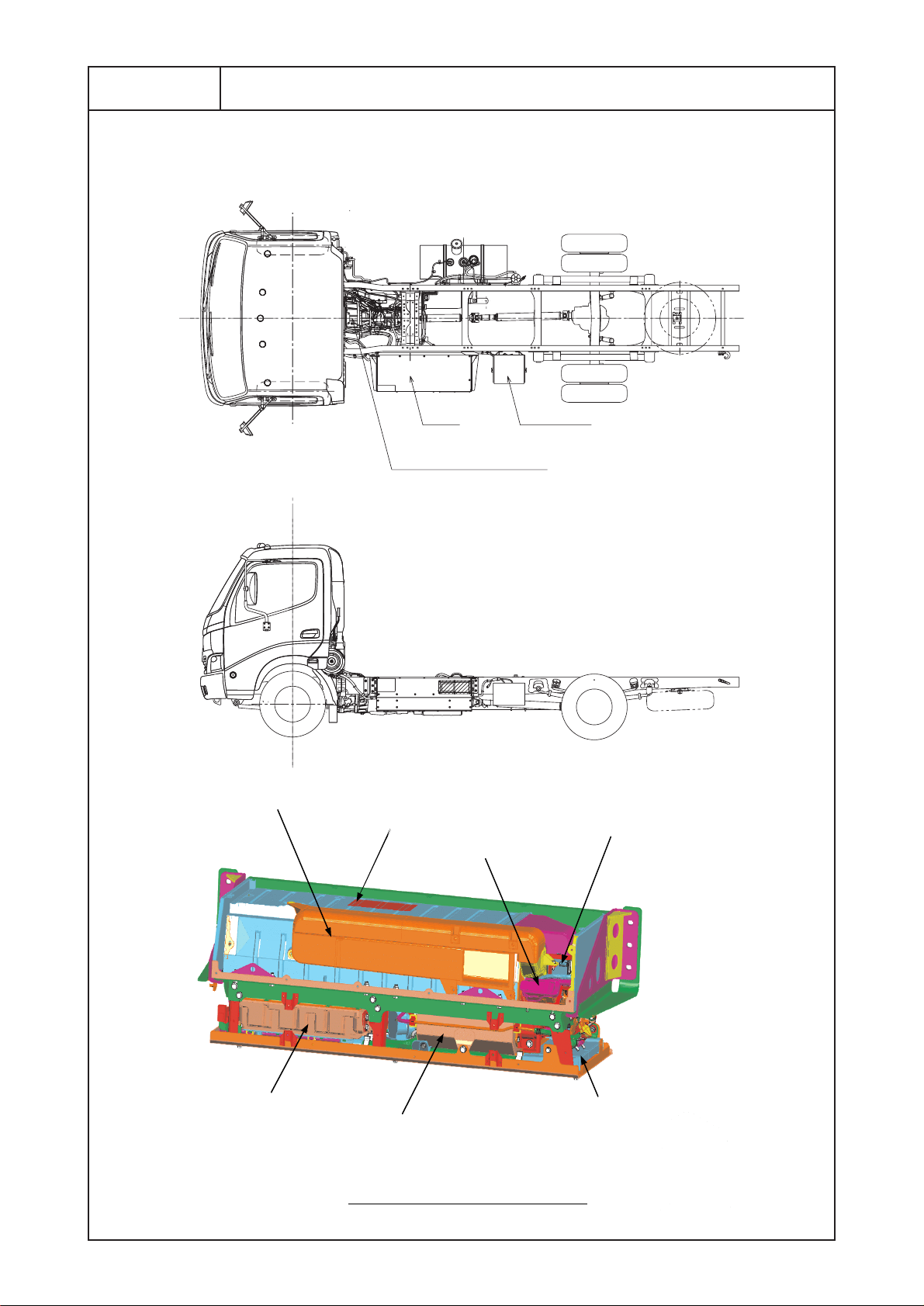
PRECAUTION ON BODY MOUNTING WORK
Installation position of hybrid related equipment.
BATTERYPCU
MOTOR GENERATOR
INVERTER
ECU BOX
(HV-ECU, BATTERY ECU,
KINDS OF RELAIES)
RADIATOR
FOR INVERTER
NICKEL METAL HYDRIDE (Ni-MH)
BATTERY
SERVICE PLUG
COOLING DUCT
COOLING FAN
FOR BATTERY
INNER STRUCTURE OF PCU
Page 31

2 - 9 - 2
KK-XZU215C
Precaution on body mounting work.
Before starting to mount a body please make sure to contact a
distributor and receive suitable advice.
Carry out mounting a body paying attention to following
precautions.
• Make sure to always wear the electric insulation equipment
(insulation rubber gloves .etc) while working.
• Prior to performing the body mounting, turn the starter switch
to OFF, pull out the SERVICE PLUG of PCU and wait more
than 7 minutes. (see following figures)
Strictly observe abouve precautions to avoid receiving electric
shock.
• Do not attach the SERVICE PLUG which removed till the end
of work.
It takes 7 minutes to discharge the electricity of high-voltage
condenser of the inverter.
SERVICE PLUG LID
PCU
SERVICE PLUG
Procedure of the SERVICE PLUG removal
Procedure of the SERVICE PLUG installation
y
p
*
Slide the lever.
Rais the lever and draw out the
SERVICE PLUG.
Slide the lever
certainl
till it is locked.
Insert the SERVICE PLUG
and
ush down the lever.
Page 32

2 - 9 - 3
KK-XZU215C
• Pay attention to handle high voltage harness wires which are
rolled by orange color tape.
• Never get on the hybrid system equipment such as the battery
and the inverter. You might get an electric shock or damage a
equipment.
• During work, protect PCU cover to prevent blemish and dirt
adheres.
• The SERVICE PLUG LID (hereinafter termed LID) is
directional.
When attaching the LID, the air intake port of LID must be
placed in the direction of vehicle front. (see following figures)
If the LID is placed in the wrong direction, the intake port of
Ni-MH BATTERY COOLING DUCT will be coverd and the
battery gets hot unusually.
It causes other faults.
Fr
OK
Place the intake port (wire net part) in
the direction of vehicle front.
NG
Fr
The state which attached the service plug lid in
the wrong direction.
The inner service plug can be seen from the
intake port (wire net part).
The intake port of cooling duct is coverd and
the battery can not be cooled.
Page 33

2 - 10 -1
KK-XZU215C
THE NOISE MEASURES OF THE AM RADIO
Make sure to connect 2 earth wires between body and / or
equipment(hereinafter termed body) and chassis frame for the
noise preventing of the AM radio by the hybrid system.
• Between body and chassis frame
Connect one side of the earth wire to the center part of front
end of body and the other side to the chassis frame with the
fitting nut of parking brake cable bracket.
Tightening torque of nut : 18±5N·m
In order to secure an electric conductivity remove the paint of
the fixing part.
Make sure to give anti-rust treatment to the fixing part after
installing the each wire.
The above figure is the example witch connected the earth
wire to the center part of front end of aluminum van and
the right side of chassis frame.
Fixing part of body
Earth wire
Remove the paint of
fixing part
Page 34

2 - 10 -2
KK-XZU215C
• Between body and motor generator
Connect one side of the earth wire to the center part of front
end body and the other side to the grounding terminal of the
motor generator together with the earth wire of the motor
generator with the existing bolt.(See the following figure)
Tightening torque of bolt : 24±7.2N·m
Tie the additional earth wire to the nearby cable with tie-rap.
Additional earth wires are contained in the package in the
cab.
Part number of earth cable (Assembly part number : 82046-
37160)
Prepare bolts, nuts and washers to needed for mounting body
by body builder.
Grounding terminal
Earth wire of
motor generator
FR
Place ti be fitted Part number
Between body and parking brake cable bracket
Between body and motor generator
82284-37160
Page 35

3. CHASSIS MASS & FRAME SECTION MODULUS
CHASSIS MASS ・・・・・・・・・・・・・・・・・・・・・・・・・・・・・・・・・・・・・・・・・・・・・・ 3 - 1
FRAME SECTION MODULUS
・・・・・・・・・・・・・・・・・・・・・・・・・・・・・・・・・・ 3 - 2
KK-XZU215C
Page 36

3. CHASSIS MASS & FRAME SECTION MODULUS
3 - 1 - 1
KK-XZU215C
MODEL
GRAVITY GRAVITY GRAVITY GRAVITY GRAVITY
MASS POSITION MASS POSITION MASS POSITION MASS POSITION MASS POSITION
FROM F.A.C FROM F.A.C FROM F.A.C FROM F.A.C FROM F.A.C
(kg) (m) (kg·m) (kg) (m) (kg·m) (kg) (m) (kg·m) (kg) (m) (kg·m) (kg) (m) (kg·m)
FRONT BUMPER 7 -0.920 -6.440 7 -0.920 -6.440 7 -0.920 -6.440 13 -0.970 -12.610 13 -0.970 -12.610
CAB FRONT 211 -0.827 -174.497 211 -0.827 -174.497 211 -0.827 -174.497 205 -0.867 -177.735 205 -0.867 -177.735
CAB FRONT MTG. 23 -0.827 -19.021 23 -0.827 -19.021 23 -0.827 -19.021 23 -0.867 -19.941 23 -0.867 -19.941
STEERING GEAR BOX 19 -0.715 -13.585 19 -0.715 -13.585 19 -0.715 -13.585 20 -0.755 -15.100 20 -0.755 -15.100
RADIATOR 16 -0.220 -3.520 16 -0.220 -3.520 16 -0.220 -3.520 16 -0.220 -3.520 16 -0.220 -3.520
STEERING CONTROL 2 -0.200 -0.400 2 -0.200 -0.400 2 -0.200 -0.400 3 -0.190 -0.570 3 -0.190 -0.570
ENGINE FRONT 373 0.175 65.275 363 0.175 63.525 373 0.175 65.275 377 0.175 65.975 377 0.175 65.975
CONTROL 7 0.440 3.080 7 0.440 3.080 7 0.440 3.080 7 0.480 3.360 7 0.480 3.360
ENGINE ROOM (COVER) 1.4 0.000 0.000 1.4 0.000 0.000 1.4 0.000 0.000 1.4 0.000 0.000 1.4 0.000 0.000
AIR CLEANER 7 0.790 5.530 7 0.790 5.530 7 0.790 5.530 11 0.385 4.235 11 0.385 4.235
CAB REAR 104 0.455 47.320 104 0.455 47.320 104 0.455 47.320 164 0.465 76.260 164 0.465 76.260
CAB REAR MTG. 30 0.455 13.650 30 0.455 13.650 30 0.455 13.650 35 0.465 16.275 35 0.465 16.275
ENGINE REAR 112 1.114 124.768 112 1.114 124.768 112 1.114 124.768 113 1.180 133.340 113 1.180 133.340
REAR SPLASH 2 0.450 0.900 2 0.450 0.900 2 0.450 0.900 4 0.460 1.840 4 0.460 1.840
BRAKE SYSTEM 4 -0.600 -2.400 4 -0.600 -2.400 4 -0.600 -2.400 4 -0.600 -2.400 7 -0.600 -4.200
ELECTRIC SYSTEM 14 0.400 5.600 14 0.400 5.600 14 0.400 5.600 15 0.500 7.500 15 0.500 7.500
EXHAUST SYSTEM 27 1.261 34.047 31 1.545 47.895 27 1.261 34.047 27 1.269 34.263 27 1.269 34.263
BATTERY 32 1.157 37.024 32 1.157 37.024 32 1.157 37.024 38 1.207 45.866 38 1.207 45.866
FUEL TANK 76 1.335 101.460 76 1.335 101.460 104 2.140 222.560 104 1.325 137.800 104 1.325 137.800
FUEL TANK (SUB)
A/C
PROPELLER SHAFT (FRONT)
PROPELLER SHAFT (REAR) 12 1.800 21.600 12 1.800 21.600 25 2.240 56.000 14 2.090 29.260 14 2.090 29.260
FRAME ETC. 184 1.335 245.640 217 1.270 275.590 258 1.870 482.460 211 1.360 286.960 211 1.360 286.960
SPARE TIRE CARRIER 7 3.160 22.120 7 3.370 23.590 7 4.295 30.065 7 1.850 12.950 7 1.850 12.950
SPARE TIRE 32.4 3.160 102.384 33.2 3.370 111.884 32.4 4.295 139.158 32.4 1.850 59.940 38.4 1.850 71.040
FRONT SUSPENSION 60 0.000 0.000 83 0.000 0.000 73 0.000 0.000 72 0.000 0.000 72 0.000 0.000
REAR SUSPENSION 112 2.525 282.800 96 2.525 242.400 134 3.400 455.600 128 2.810 359.680 128 2.810 359.680
TOOL BOX
TORSION BAR & SUPPORT (4WD)
REAR BUMPER
P.T.O
CAB TILT
PCU
AIR BUG
STABILIZER (FRONT)
STABILIZER (REAR)
DISCHARGE HEAD LAMP
TOOL 10 0.500 5.000 10 0.500 5.000 10 0.500 5.000 10 0.500 5.000 10 0.500 5.000
TOTAL 1484.8 0.605 898.335 1519.6 0.599 910.953 1634.8 0.923 1508.174 1654.8 0.634 1048.628 1663.8 0.636 1057.928
WHEEL BASE (m) 2.525 2.525 3.400 2.810 2.810
FRONT REAR TOTAL FRONT REAR TOTAL FRONT REAR TOTAL FRONT REAR TOTAL FRONT REAR TOTAL
(kg) (kg) (kg) (kg) (kg) (kg) (kg) (kg) (kg) (kg) (kg) (kg) (kg) (kg) (kg)
SPRUNG MASS 1,129 356 1,485 1,159 361 1,520 1,191 444 1,635 1,282 373 1,655 1,287 376 1,664
UNSPRUNG MASS 189 249 438 189 344 533 189 344 533 213 337 550 229 361 590
CHASSIS MASS 1,318 605 1,923 1,348 705 2,053 1,380 788 2,168 1,495 710 2,205 1,516 737 2,254
GRAVITY POSITION FROM F.A.C (m)
GRAVITY HEIGHT FROM GROUND (m)
AUSXZU201 03T002
CHASSIS MASS
CHASSIS MASS : On Std. spec, filled with lubricants, coolant and fuel, with spare tire and Std. tool sets.
XZU307L-HKMLB3 XZU307L-HKMMB3
MOMENT
ITEMS
FROM
F.A.C
MOMENT
FROM
F.A.C
MOMENT
FROM
F.A.C
XZU407L-HKMMD3 XZU407L-HKMQD3XZU347L-HKMMB3
MOMENT
FROM
F.A.C
MOMENT
FROM
F.A.C
0.794
0.524
1.235
0.565 0.555
0.9050.867
0.919
0.6670.628
Page 37

3 - 1 - 2
KK-XZU215C
CHASSIS MASS : On Std. spec, filled with lubricants, coolant and fuel, with spare tire and Std. tool sets.
MODEL
GRAVITY GRAVITY GRAVITY GRAVITY GRAVITY
MASS POSITION MASS POSITION MASS POSITION MASS POSITION MASS POSITION
FROM F.A.C FROM F.A.C FROM F.A.C FROM F.A.C FROM F.A.C
(kg) (m) (kg·m) (kg) (m) (kg·m) (kg) (m) (kg·m) (kg) (m) (kg·m) (kg) (m) (kg·m)
FRONT BUMPER 13 -0.970 -12.610 13 -0.970 -12.610 13 -0.970 -12.610 13 -0.970 -12.610 13 -0.970 -12.610
CAB FRONT 205 -0.867 -177.735 205 -0.867 -177.735 205 -0.867 -177.735 205 -0.867 -177.735 205 -0.867 -177.735
CAB FRONT MTG. 23 -0.867 -19.941 23 -0.867 -19.941 23 -0.867 -19.941 23 -0.867 -19.941 23 -0.867 -19.941
STEERING GEAR BOX 20 -0.755 -15.100 20 -0.755 -15.100 20 -0.755 -15.100 20 -0.755 -15.100 20 -0.755 -15.100
RADIATOR 16 -0.220 -3.520 16 -0.220 -3.520 16 -0.220 -3.520 16 -0.220 -3.520 16 -0.220 -3.520
STEERING CONTROL 3 -0.190 -0.570 3 -0.190 -0.570 3 -0.190 -0.570 3 -0.190 -0.570 3 -0.190 -0.570
ENGINE FRONT 387 0.175 67.725 387 0.175 67.725 377 0.175 65.975 387 0.175 67.725 387 0.175 67.725
CONTROL 7 0.480 3.360 7 0.480 3.360 7 0.480 3.360 7 0.480 3.360 7 0.480 3.360
ENGINE ROOM (COVER) 1.4 0.000 0.000 1.4 0.000 0.000 1.4 0.000 0.000 1.4 0.000 0.000 1.4 0.000 0.000
AIR CLEANER 11 0.385 4.235 11 0.385 4.235 11 0.385 4.235 11 0.385 4.235 11 0.385 4.235
CAB REAR 164 0.465 76.260 164 0.465 76.260 164 0.465 76.260 164 0.465 76.260 164 0.465 76.260
CAB REAR MTG. 35 0.465 16.275 35 0.465 16.275 35 0.465 16.275 35 0.465 16.275 35 0.465 16.275
ENGINE REAR 121 1.180 142.780 121 1.180 142.780 113 1.180 133.340 121 1.180 142.780 121 1.180 142.780
REAR SPLASH 4 0.460 1.840 4 0.460 1.840 4 0.460 1.840 4 0.460 1.840 4 0.460 1.840
BRAKE SYSTEM 7 -0.600 -4.200 7 -0.600 -4.200 4 -0.600 -2.400 7 -0.600 -4.200 7 -0.600 -4.200
ELECTRIC SYSTEM 15 0.500 7.500 15 0.500 7.500 15 0.500 7.500 15 0.500 7.500 15 0.500 7.500
EXHAUST SYSTEM 27 1.269 34.263 27 1.269 34.263 27 1.269 34.263 27 1.269 34.263 27 1.763 47.601
BATTERY 38 1.207 45.866 38 1.207 45.866 38 1.207 45.866 38 1.207 45.866 38 1.207 45.866
FUEL TANK 104 1.325 137.800 104 1.325 137.800 104 1.945 202.280 104 1.945 202.280 104 1.945 202.280
FUEL TANK (SUB)
A/C
PROPELLER SHAFT (FRONT)
PROPELLER SHAFT (REAR) 14 2.090 29.260 14 2.090 29.260 26 2.400 62.400 26 2.400 62.400 26 2.400 62.400
FRAME ETC. 211 1.360 286.960 234 1.360 318.240 268 1.790 479.720 268 1.790 479.720 268 1.790 479.720
SPARE TIRE CARRIER 7 1.850 12.950 7 1.850 12.950 7 4.400 30.800 7 4.400 30.800 7 4.400 30.800
SPARE TIRE 38.4 1.850 71.040 46.5 1.850 86.025 32.4 4.400 142.560 38.4 4.400 168.960 46.5 4.400 204.600
FRONT SUSPENSION 72 0.000 0.000 72 0.000 0.000 72 0.000 0.000 72 0.000 0.000 81 0.000 0.000
REAR SUSPENSION 128 2.810 359.680 128 2.810 359.680 128 3.430 439.040 128 3.430 439.040 128 3.430 439.040
TOOL BOX
TORSION BAR & SUPPORT (4WD)
REAR BUMPER
P.T.O
CAB TILT
PCU
AIR BUG
STABILIZER (FRONT)
STABILIZER (REAR)
DISCHARGE HEAD LAMP
TOOL 10 0.500 5.000 10 0.500 5.000 10 0.500 5.000 10 0.500 5.000 10 0.500 5.000
TOTAL 1681.8 0.636 1069.118 1712.9 0.651 1115.383 1723.8 0.881 1518.838 1750.8 0.888 1554.628 1767.9 0.907 1603.606
WHEEL BASE (m) 2.810 2.810 3.400 3.430 3.430
FRONT REAR TOTAL FRONT REAR TOTAL FRONT REAR TOTAL FRONT REAR TOTAL FRONT REAR TOTAL
(kg) (kg) (kg) (kg) (kg) (kg) (kg) (kg) (kg) (kg) (kg) (kg) (kg) (kg) (kg)
SPRUNG MASS 1,301 380 1,682 1,316 397 1,713 1,281 443 1,724 1,298 453 1,751 1,300 468 1,768
UNSPRUNG MASS 229 361 590 256 415 671 213 337 550 229 361 590 256 415 671
CHASSIS MASS 1,530 741 2,272 1,572 812 2,384 1,494 780 2,274 1,527 814 2,341 1,556 883 2,439
GRAVITY POSITION FROM F.A.C (m)
GRAVITY HEIGHT FROM GROUND (m)
AUSXZU201 03T003
XZU407L-HKFQD3 XZU417L-HKMMD3
MOMENT
ITEMS
FROM
F.A.C
MOMENT
FROM
F.A.C
MOMENT
FROM
F.A.C
MOMENT
FROM
F.A.C
XZU417L-HKFRD3XZU407L-HKFRD3 XZU417L-HKFQD3
MOMENT
FROM
F.A.C
0.917
0.667
1.1930.957
0.660 0.660
0.628 0.667
1.2411.176
Page 38

3 - 1 - 3
KK-XZU215C
CHASSIS MASS : On Std. spec, filled with lubricants, coolant and fuel, with spare tire and Std. tool sets.
MODEL
GRAVITY GRAVITY GRAVITY
MASS POSITION MASS POSITION MASS POSITION
FROM F.A.C FROM F.A.C FROM F.A.C
(kg) (m) (kg·m) (kg) (m) (kg·m) (kg) (m) (kg·m)
FRONT BUMPER 13 -0.970 -12.610 13 -0.970 -12.610 13 -0.970 -12.610
CAB FRONT 205 -0.867 -177.735 205 -0.867 -177.735 205 -0.867 -177.735
CAB FRONT MTG. 23 -0.867 -19.941 23 -0.867 -19.941 23 -0.867 -19.941
STEERING GEAR BOX 20 -0.755 -15.100 20 -0.755 -15.100 20 -0.755 -15.100
RADIATOR 16 -0.220 -3.520 16 -0.220 -3.520 16 -0.220 -3.520
STEERING CONTROL 3 -0.190 -0.570 3 -0.190 -0.570 3 -0.190 -0.570
ENGINE FRONT 387 0.175 67.725 387 0.175 67.725 402 0.175 70.350
CONTROL 7 0.480 3.360 7 0.480 3.360 7 0.480 3.360
ENGINE ROOM (COVER) 1.4 0.000 0.000 1.4 0.000 0.000 3 0.000 0.000
AIR CLEANER 11 0.385 4.235 11 0.385 4.235 11 0.385 4.235
CAB REAR 164 0.465 76.260 164 0.465 76.260 164 0.465 76.260
CAB REAR MTG. 35 0.465 16.275 35 0.465 16.275 35 0.465 16.275
ENGINE REAR 121 1.180 142.780 121 1.180 142.780 148 1.293 191.364
REAR SPLASH 4 0.460 1.840 4 0.460 1.840 4 0.460 1.840
BRAKE SYSTEM 7 -0.600 -4.200 7 -0.600 -4.200 7 -0.600 -4.200
ELECTRIC SYSTEM 15 0.500 7.500 15 0.500 7.500 20 0.500 10.000
EXHAUST SYSTEM 27 1.903 51.381 27 1.903 51.381 33 1.500 49.500
BATTERY 38 1.207 45.866 38 1.207 45.866 51 2.461 125.511
FUEL TANK 104 2.385 248.040 104 2.385 248.040 104 1.945 202.280
FUEL TANK (SUB)
A/C
PROPELLER SHAFT (FRONT)
PROPELLER SHAFT (REAR) 28 2.620 73.360 28 2.620 73.360 25 2.400 60.000
FRAME ETC. 280 2.030 568.400 280 2.030 568.400 241 1.780 428.980
SPARE TIRE CARRIER 7 4.815 33.705 7 4.815 33.705 7 4.390 30.730
SPARE TIRE 33.1 4.815 159.377 46.5 4.815 223.898 38.4 4.815 184.896
FRONT SUSPENSION 72 0.000 0.000 81 0.000 0.000 72 0.000 0.000
REAR SUSPENSION 128 3.870 495.360 161 3.870 623.070 128 3.430 439.040
TOOL BOX
TORSION BAR & SUPPORT (4WD)
REAR BUMPER
P.T.O
CAB TILT
PCU 122 1.300 158.600
AIR BUG
STABILIZER (FRONT)
STABILIZER (REAR)
DISCHARGE HEAD LAMP
TOOL 10 0.500 5.000 10 0.500 5.000 10 0.500 5.000
TOTAL 1759.5 1.004 1766.788 1814.9 1.079 1959.019 1912.4 0.954 1824.545
WHEEL BASE (m) 3.870 3.870 3.430
FRONT REAR TOTAL FRONT REAR TOTAL FRONT REAR TOTAL
(kg) (kg) (kg) (kg) (kg) (kg) (kg) (kg) (kg)
SPRUNG MASS 1,303 457 1,760 1,309 506 1,815 1,380 532 1,912
UNSPRUNG MASS 229 361 590 256 415 671 229 361 590
CHASSIS MASS 1,532 818 2,350 1,565 921 2,486 1,609 893 2,502
GRAVITY POSITION FROM F.A.C (m)
GRAVITY HEIGHT FROM GROUND (m)
AUSXZU201 03T004
XZU427L-HKFQD3
MOMENT
ITEMS
FROM
F.A.C
XZU427L-HKFRD3
MOMENT
FROM
F.A.C
XKU417L-HKFQB3
MOMENT
FROM
F.A.C
1.347
0.667
1.434
1.224
0.6670.660
Page 39

FRAME SECTION MODULUS (MAIN FRAME ON BOTH SIDE)
3 - 2 - 1
KK-XZU215C
MODEL : XZU307L-HKMLB3
Page 40

FRAME SECTION MODULUS (MAIN FRAME ON BOTH SIDE)
3 - 2 - 2
KK-XZU215C
MODEL : XZU307L-HKMMB3
Page 41

FRAME SECTION MODULUS (MAIN FRAME ON BOTH SIDE)
3 - 2 - 3
KK-XZU215C
MODEL : XZU347L-HKMMB3
Page 42

FRAME SECTION MODULUS (MAIN FRAME ON BOTH SIDE)
3 - 2 - 4
KK-XZU215C
MODEL : XZU407L-HKMMD3
XZU407L-HKMQD3
XZU407L-HKFQD3
XZU407L-HKFRD3
Page 43

FRAME SECTION MODULUS (MAIN FRAME ON BOTH SIDE)
3 - 2 - 5
KK-XZU215C
MODEL : XZU417L-HKMMD3 XKU417L-HKFQB3
XZU417L-HKFQD3
XZU417L-HKFRD3
Page 44

FRAME SECTION MODULUS (MAIN FRAME ON BOTH SIDE)
3 - 2 - 6
KK-XZU215C
MODEL : XZU427L-HKFQD3
XZU427L-HKFRD3
Page 45

4. SPRINGS & REAR AXLES
SPRING CHARACTERISTICS ・・・・・・・・・・・・・・・・・・・・・・・・・・・・・・・・・・ 4 - 1
MAXIMUM VERTICAL DEFLECTION OF REAR WHEELS
・・・・・・・・ 4 - 2
TRAVEL RANGE OF REAR SPRING
・・・・・・・・・・・・・・・・・・・・・・・・・・・・ 4 - 3
KK-XZU215C
Page 46

4 - 1 - 1
KK-XZU215C
4. SPRINGS & REAR AXLES
SPRING CHARACTERISTICS
1) SPRING COMBINATION
Refer to SPRING CHARACTERISTICS CHART based on
following table.
SPRING CHARACTERISTICS
MODEL
XZU307L-HKMLB3 F1 R1
XZU307L-HKMMB3 F2 F6 R2 R5
XZU347L-HKMMB3 F2 F6 R2 R5
XZU407L-HKMMD3 F3 F7 R3 R4
XZU407L-HKMQD3 F4 F5 R3 R4
XZU407L-HKFQD3 F4 F5 R3 R4
XZU407L-HKFRD3 F5 F8 R4 R6
XZU417L-HKMMD3 F3 F7 R3 R4
XZU417L-HKFQD3 F4 F5 R3 R4
XZU417L-HKFRD3 F5 F8 R4 R6
XZU427L-HKFQD3 F4 F5 R3 R4
XZU427L-HKFRD3 F5 F8 R4 R6
XKU417L-HKFQB3 F4 F5 R3 R4
FRONT REAR
STD OPT STD OPT
AUSXZU201 04T001
Page 47

2) FRONT LEAF SPRING
(1) SPRING CHARACTERISTICS CHART "F1"
(2) SPRING CHARACTERISTICS CHART "F2"
4 - 1 - 2
KK-XZU215C
Page 48

(3) SPRING CHARACTERISTICS CHART "F3"
(4) SPRING CHARACTERISTICS CHART "F4"
4 - 1 - 3
KK-XZU215C
Page 49

(5) SPRING CHARACTERISTICS CHART "F5"
(6) SPRING CHARACTERISTICS CHART "F6"
4 - 1 - 4
KK-XZU215C
Page 50

(7) SPRING CHARACTERISTICS CHART "F7"
(8) SPRING CHARACTERISTICS CHART "F8"
4 - 1 - 5
KK-XZU215C
Page 51

3) REAR LEAF SPRING
(1) SPRING CHARACTERISTICS CHART "R1"
4 - 1 - 6
KK-XZU215C
Page 52

(2) SPRING CHARACTERISTICS CHART "R2"
4 - 1 - 7
KK-XZU215C
Page 53

4 - 1 - 8
KK-XZU215C
(3) SPRING CHARACTERISTICS CHART "R3"
Page 54

4 - 1 - 9
KK-XZU215C
(4) SPRING CHARACTERISTICS CHART "R4"
Page 55

(5) SPRING CHARACTERISTICS CHART "R5"
4 - 1 - 10
KK-XZU215C
Page 56

4 - 1 - 11
KK-XZU215C
(6) SPRING CHARACTERISTICS CHART "R6"
Page 57

4 - 2
KK-XZU215C
MAXIMUM VERTICAL DEFLECTION OF REAR WHEELS
Measurements for the maximum deflection for on tire and for
simultaneous left and right deflection are shown below.
When you mount the body, allow a clearance of at least 30mm so
as not to obstruct tire deflection.
D
A
BC
D
A
BC
F4 RTIRES2
Deflection of rear tires
Maximum deflection for
one side wheels.
Maximum simultaneous deflection
right and left wheels.
With tire chain : Dimensions A and B are added 50mm.
1.SINGLE TIRE
2.DOUBLE TIRE
MODEL TIRE SIZE A B C D REAR TIRE
XZU307L-HKMLB3 205/75R16C 139 132 42 198 SINGLE
XZU307L-HKMMB3 205/75R16C 137 97 96 120
XZU347L-HKMMB3 205/75R16C 137 97 96 120
XZU407L-HKMMD3 205/75R16C 100 54 125 113
XZU407L-HKMQD3 215/85R16 124 79 128 127
XZU407L-HKFQD3 215/85R16 124 79 128 127
XZU407L-HKFRD3 215/75R17.5 120 75 134 123
XZU417L-HKMMD3 205/75R16C 100 54 125 113
XZU417L-HKFQD3 215/85R16 124 79 128 127
XZU417L-HKFRD3 215/75R17.5 120 75 134 123
XZU427L-HKFQD3 215/85R16 124 79 128 127
XZU427L-HKFRD3 215/75R17.5 120 75 134 123
XKU417L-HKFQB3 215/85R16C 124 79 128 127
DOUBLE
Page 58

4 - 3
KK-XZU215C
TRAVEL RANGE OF REAR SPRING
During driving, the shackle of the main spring slides beyond the end of the rear
bracket.
REAR SHACKLE
REAR LEAF SPRING
A
Do not mount any parts of
body inside of the this range.
FRONT
Unit : mm
MODEL A (min.)
XZU307L-HKMMB3
XZU347L-HKMMB3
XZU407L-HKMMD3
XZU407L-HKMQD3
XZU407L-HKFQD3
XZU407L-HKFRD3
XZU417L-HKMMD3
XZU417L-HKFQD3
XZU417L-HKFRD3
XZU427L-HKFQD3
XZU427L-HKFRD3
XKU417L-HKFQB3
AUSXZU201 04T003
MODEL : XZU307L-HKMLB3
100
130
Page 59

5. PTO AND CONTROL
LAYOUT OF POWER LINE ・・・・・・・・・・・・・・・・・・・・・・・・・・・・・・・・・・・・ 5 - 1
TRANSMISSION SIDE POWER TAKE OFF (OPT) ・・・・・・・・・・・・・・・・ 5 - 2
ENGINE CONTROL FOR BODY OR EQUIPMENT ・・・・・・・・・・・・・・・・ 5 - 3
REAR BODY CONTROL LEVER (OPT) ・・・・・・・・・・・・・・・・・・・・・・・・ 5 - 4
KK-XZU215C
Page 60

LAYOUT OF POWER LINE
5. PTO AND CONTROL
5 - 1
KK-XZU215C
MODEL
XZU307L-HKMLB3
XZU307L-HKMMB3
XZU347L-HKMMB3
XZU407L-HKMMD3
XZU407L-HKMQD3
XZU407L-HKFQD3
XZU407L-HKFRD3
XZU417L-HKMMD3
XZU417L-HKFQD3
XZU417L-HKFRD3
XZU427L-HKFQD3
XZU427L-HKFRD3
E/G
MODEL
N04C-TU M550
N04C-TU M550
N04C-TU M550
N04C-TV M550 240 153 4° 436 287 944 0 0° 1
N04C-TV M550 240 153 4° 436 287 944 0 0° 1
N04C-TV MYY6 240 153 4° 357 221 860 0 0° 2
N04C-TV MYY6 240 153 4° 357 221 860 0 0° 2
N04C-TV M550 240 153 4° 436 287 944 0 0° 1
N04C-TV MYY6 240 153 4° 357 221 860 0 0° 2
N04C-TV MYY6 240 153 4° 357 221 860 0 0° 2
N04C-TV MYY6 240 153 4° 357 221 860 0 0° 2
N04C-TV MYY6 240 153 4° 357 221 860 0 0° 2
T/M
MODEL
ABCDEFGH
247 180
247 180
247 180
436 287 944
3°
436 287 944
3°
436 287 944
3°
00° – –
00° 1
00° 1
PTO
T/M
No.
REAR
BODY
CONTROL
(OPT)
DUMP
LEVER
DUMP
LEVER
DUMP
LEVER
DUMP
LEVER
DUMP
LEVER
DUMP
LEVER
DUMP
LEVER
DUMP
LEVER
DUMP
LEVER
DUMP
LEVER
DUMP
LEVER
AUSXZU201 05T001
Page 61

5 - 2 - 1
KK-XZU215C
TRANSMISSION SIDE POWER TAKE OFF (OPT)
When the body require transmission Power Take Off (PTO),
genuine PTO equipment and related parts should be supplied
as shown below.
[T/M PTO No.1]
1) Transmission Series by Vehicle Model
2) Data of the PTO Output Shaft
3) Necessary Parts
[NOTE]
1. Parts mentioned above table shows transmission PTO unit only.
2. Other related parts of transmission PTO control, please contact each Hino
sales dealer or distributor.
Model Transmission series
XZU307L-HKMMB3
XZU347L-HKMMB3
XZU407L-HKMMD3
XZU407L-HKMQD3
XZU417L-HKMMD3
M550
AUSXZU201 05T006
Transmission
series
Permissible torque
(N·m{kgf·m} at r/min)
PTO control
type
Direction of
rotation
M550 245 {25} / 1,000
Vacuum
control
Reverse to
engine
Nut
Stud bolt
Bolt
Gasket, PTO case
Power take off assy
Parts name
Rev.
5th
4th
3rd
2nd
1st
Transmission gear ratio
Transmission model
94130-61000
92132-81025
90119-10372
33162-37030
36610-37280
Parts No.
4.625
0.738
1.000
1.556
2.911
4.981
M550
05
05
01
01
01
Lockwasher 94512-01000 05
PTO control type Vacuum
Q'ty /
unit
AUSXZU201 05T007
Page 62

5 - 2 - 2
KK-XZU215C
4) PTO Installation Procedure
(1) Drain the transmission oil.
(Do not remove the drain plug while the oil is hot, or you will
scaled yourself.)
(2) Remove the PTO cover which is at the left of the transmission.
( Do not reuse the bolts and gasket that you remove at this
time.)
(3) Clean the PTO mounting surface on the transmission side.
(4) Prepare the necessary parts, referring to paragraph "3")
(5) Install the stud bolts to the PTO mounting of the transmission
case.
(6) Fit the gasket and PTO on the PTO mounting position and
tighten the fitting bolts and nuts.
Tightening torque for stud bolts : 36.3N·m {370kgf·cm}
(7) After attaching the PTO, turn the output shaft coupling a few
revolutions to be sure that it turns freely.
(8) When you refill the transmission oil, increase the amount by
0.3 liters to allow for the PTO.
5) Gear Layout and Gear Ratio
Gear ratio : i = N2/N1 x N3/N2 x N5/N4
[NOTES]
1. Number of revolutions of PTO output shaft
= number of revolutions of engine x1/ i
2. The PTO output shaft turns in the opposite direction to the engine.
M550 32 35 34 31 40 1.371
Transmission N1 N2 N3 N4 N5 i
Page 63

5 - 2 - 3
KK-XZU215C
6) Detail of M550 Transmission
Unit : mm
DRIVE GEAR SPECIFICATION (T/M SIDE /3rd COUNTER GEAR)
TO T/M CASE
FRONT SURFACE 149
130
108
124 ±0.1
70
16 ±0.1
142
164
54
101
MAINSHAFT CENTER LINE
6-M10x1.25
DEPTH 24
DRIVE GEAR
(C)
1.5
+0.05
0
AUSXZU201 05F001
Tooth profile
Number of teeth
Normal module
Normal pressure angle
Helix angle (and direction)
Standard pitch circle diameter
Base circle diameter
Normal circular thickness
Over ball diameter
Used ball diameter
Face width
Rotation backlash
Addendum modification coefficient
Gear layout
Outside diameter
Whole depth
Semi-topping
Helical gear
35
2.650
17˚
29˚ (Right)
106.046
3.9171
113.403
5.000
20 ±0.2
0.05
-0.1515
100.106
112.750
8.1
0.2
Tooth
thickness
0
-0.1
0
-0.1
INPUT
SHAFT
PTO
35
32
AUSXZU201 05T005
Page 64

5 - 2 - 4
KK-XZU215C
7) Transmission PTO mounting (M550)
Vacuum control type
Unit : mm
[NOTE] 1) The devices on the body or equipment side (e. g. oil pump)
must be mounted at the same angle as engine to the body.
(Direct mounting the devices to the PTO output flange is
strictly prohibited.)
2) The three-dimensional angle of the universal joint of the
drive shaft should be less than 6˚.
Page 65

5 - 2 - 5
KK-XZU215C
• Detail of PTO Flange
Unit : mm
• Detail of PTO Output Shaft
Page 66

5 - 2 - 6
KK-XZU215C
[T/M PTO No.2]
1) Transmission Series by Vehicle Model
2) Data of the PTO Output Shaft
3) Necessary Parts
[NOTE]
1. Parts mentioned above table shows transmission PTO unit only.
2. Other related parts of transmission PTO control, please contact each Hino
sales dealer or distributor.
Model Transmission series
XZU407L-HKFQD3
XZU407L-HKFRD3
XZU417L-HKFQD3
XZU417L-HKFRD3
XZU427L-HKFQD3
XZU427L-HKFRD3
MYY6S
AUSXZU201 05T012
Transmission
series
Permissible torque
(N·m{kgf·m} at r/min)
PTO control
type
Direction of
rotation
MYY6S 196 {20} / 1,000
Electronic
control
Reverse to
engine
AUSXZU201 05T013
Nut
Stud bolt
Power take off assy
Parts name
Rev.
6th
4th
3rd
2nd
1st
Transmission gear ratio
Transmission model
94130-61000
90031-16079
36610-37290
Parts No.
PTO control type Electronic
5.701
0.759
5th 1.000
1.297
1.862
3.434
5.979
MYY6S
06
06
01
Lockwasher 94512-01000 06
Q'ty /
unit
AUSXZU201 05T014
Page 67

5 - 2 - 7
KK-XZU215C
4) PTO Installation Procedure
(1) Drain the transmission oil.
(Do not remove the drain plug while the oil is hot, or you will
scaled yourself.)
(2) Remove the PTO cover which is at the left of the transmission.
( Do not reuse the bolts and gasket that you remove at this
time.)
(3) Clean the PTO mounting surface on the transmission side.
(4) Prepare the necessary parts, referring to paragraph "3")
(5) Install the stud bolts to the PTO mounting of the transmission
case.
(6) Apply liquid gasket 'THREEBOND
1215' or 'LOCKTITE 5127
(FMD-127)' to PTO sealing surface
of transmission case as shown.
Appling methods
1) Remove moisture and oils from
sealing surface before appling.
2) Dia of liquid gasket is 2 min.
3) Liquid gasket bead must be
continued all round.
(7) Fit the PTO on the PTO mounting position and tighten
nuts.
Tightening torque for nuts : 36.3N·m {370kgf·cm}
(8) After attaching the PTO, turn the output shaft coupling a few
revolutions to be sure that it turns freely.
(9) When you refill the transmission oil, increase the amount by
0.3 liters to allow for the PTO.
5) Gear Layout and Gear Ratio
Gear ratio : i =N2/N1xN4/N3xN5/N4
[NOTES]
1. Number of revolutions of PTO output shaft
= number of revolutions of engine x1/ i
2. The PTO output shaft turns in the opposite direction to the engine.
MYY6S 26 47 33 31 27 1.479
Transmission N1 N2 N3 N4 N5 i
AUSXZU201 05T015
Page 68

5 - 2 - 8
KK-XZU215C
6) Detail of MYY6S Transmission
Page 69

5 - 2 - 9
KK-XZU215C
7) Transmission PTO mounting (MYY6S)
Electronic control type
Unit : mm
[NOTE] 1) The devices on the body or equipment side (e. g. oil pump)
must be mounted at the same angle as engine to the body.
(Direct mounting the devices to the PTO output flange is
strictly prohibited.)
2) The three-dimensional angle of the universal joint of the
drive shaft should be less than 6˚.
Page 70

5 - 2 - 10
KK-XZU215C
• Detail of PTO Flange
Unit : mm
• Detail of PTO Output Shaft
Unit : mm
Page 71

5 - 3 - 1
KK-XZU215C
ENGINE CONTROL FOR BODY OR EQUIPMENT
1) Fuel Injection Pump Governor
• DUTRO vehicles use the following fuel injection pump
governor.
No.
XZU307L-HKMLB3
1
XZU307L-HKMMB3
2
XZU347L-HKMMB3
3
XZU407L-HKMMD3
4
XZU407L-HKMQD3
5
XZU407L-HKFQD3
6
XZU407L-HKFRD3
7
XZU417L-HKMMD3
8
XZU417L-HKFQD3
9
XZU417L-HKFRD3
10
XZU427L-HKFQD3
11
XZU427L-HKFRD3
12
E/G
MODEL
N04C-TU
N04C-TU
N04C-TU
N04C-TV
N04C-TV
N04C-TV
N04C-TV
N04C-TV
N04C-TV
N04C-TV
N04C-TV
N04C-TV
GOVERNOR TYPE
PUMP GOVERNOR
COMMON-RAIL
TYPE
COMMON-RAIL
TYPE
COMMON-RAIL
TYPE
COMMON-RAIL
TYPE
COMMON-RAIL
TYPE
COMMON-RAIL
TYPE
COMMON-RAIL
TYPE
COMMON-RAIL
TYPE
COMMON-RAIL
TYPE
COMMON-RAIL
TYPE
COMMON-RAIL
TYPE
COMMON-RAIL
TYPE
ELECTRONIC CONTROL TYPE DENSO
ELECTRONIC CONTROL TYPE DENSO
ELECTRONIC CONTROL TYPE DENSO
ELECTRONIC CONTROL TYPE DENSO
ELECTRONIC CONTROL TYPE DENSO
ELECTRONIC CONTROL TYPE DENSO
ELECTRONIC CONTROL TYPE DENSO
ELECTRONIC CONTROL TYPE DENSO
ELECTRONIC CONTROL TYPE DENSO
ELECTRONIC CONTROL TYPE DENSO
ELECTRONIC CONTROL TYPE DENSO
ELECTRONIC CONTROL TYPE DENSO
MANUFACTURERMODEL
AUSXZU201 05T016
Page 72

5 - 3 - 2
KK-XZU215C
2) Engine Accelerator
• Engine accelerator and extension harness for body control
are packed in cabin as optional equipment.
• Connect the connector of Engine accelerator with spare
connector which is provided behind the No.3 crossmember at
chassis frame LH side member.
• Should more detailed data or information with regard to
engine accelerator for body control be needed, consult
authorized Hino distributor.
Page 73

5 - 3 - 3
KK-XZU215C
Page 74

5 - 3 - 4
KK-XZU215C
3) HOW TO INSTALL ENGINE ACCELERATOR FOR BODY OR
EQUIPMENT
(1) Be sure to provide the body controller with the full speed
stopper for controlling the stroke of the sensor.
In that case, adjust the body side stroke in such a way that the
body side stopper comes in contact earlier than the sensor
side stopper.
The standard for adjustment is 1mm clearance between the
sensor side lever and stopper under the condition than the
body side lever touches the stopper. (See the following
illustration.)
• Be sure to set the sensor lever that sensor lever should be
contacted with idling stopper by adjusting body control lever
while body or equipment do not operate (while vehicle is
driving).
The clearance indicated for the stroke stopper of accelerator
stopper is just for reference. If the sensor side stopper comes
into contact earlier, a forcible stress will be imposed on the
sensor shaft and it may result in the damage of the part in
cause.
Moreover if sensor lever do not came into contact with idling
stopper may result in a bad condition of the engine while
vehicle to be driving.
Page 75

5 - 3 - 5
KK-XZU215C
(2) When fitting the cable on the sensor lever, define the direction
by pulling the cable parallelly to the direction of lever stroke so
that an imbalanced load may not be imposed on the sensor
shaft.
(See the following illustration.)
(3) Cautiones when installing the Engine accelerator sensor
(hereinafter termed the sensor).
• Never attempt to disassemble the sensor.
Do not drop the sensor or do not shock it.
Each above thing may lead malfunction and failure.
• The sensor is not integral waterproof type.
Therefore, when installing it, pay attention to avoid the direct
projection of vehicle washing water, tire splash etc.
• The usable range of temperature is -30~80°C. Use it in the
said range.
• Install the sensor in the position which can apply lubrication.
• Avoid such places where there is risk of receiving falling
matters or stones that give impact.
• Install the sensor where there is no possibility of exposing
dust, oil mist, humidity, chemical product or vibration.
If it is impossible to find such place, protect it with a cover.
• Install the wire harness certainly so that it may not twist or
not bend extremely.
• For fitting and clipping the harness wires,refer to the
COMMON manual.
• If the length of the sub-harness wire is too short, try to abtain
the same kind of the harness wire for extension.
Page 76

5 - 4
KK-XZU215C
REAR BODY CONTROL LEVER (OPT)
1) Mounting position of dump body control lever
Unit : mm
Page 77

KK-XZU215C
6. ELECTRICAL SYSTEM
FUSE BLOCK AND RELAY PANEL ・・・・・・・・・・・・・・・・・・・・・・・・・・・・ 6 - 1
ALTERNATOR OUTPUT CHARACTERISTIC
・・・・・・・・・・・・・・・・・・・・ 6 - 2
SPARE POWER TERMINALS
・・・・・・・・・・・・・・・・・・・・・・・・・・・・・・・・・・ 6 - 3
ADDITIONAL LAMPS
・・・・・・・・・・・・・・・・・・・・・・・・・・・・・・・・・・・・・・・・・・ 6 - 4
REAR COMBINATION LAMP
・・・・・・・・・・・・・・・・・・・・・・・・・・・・・・・・・・ 6 - 5
LICENSE PLATE BRACKET AND LICENSE PLATE LAMP
・・・・・・・・ 6 - 6
BACK-UP BUZZER
・・・・・・・・・・・・・・・・・・・・・・・・・・・・・・・・・・・・・・・・・・・・ 6 - 7
ELECTRICAL WIRING DIAGRAMS
・・・・・・・・・・・・・・・・・・・・・・・・・・・・・・ 6 - 8
Page 78

6 - 1 - 1
6. ELECTRICAL SYSTEM
KK-XZU215C
FUSE BLOCK AND RELAY PANEL
1) LOCATION
The fuse block and relay panel are located inside the instrument
panel as shown below.
Page 79

6 - 1 - 2
KK-XZU215C
2) FUSE BLOCK
Page 80

L
E12
+S
E29
-S
E13
L
E04
B
%4N
B
E01
L
#RC
L
K49
L
O0TLO0R
L
A04LA10LV02LH02LC08
B
C07B#CB
B
#HA
B
A03
L
E02
B
#RA
B
#OJ
L
I02
L
K04
L
C02
L
#PB
L
%4H
B
%4M
B
E11
E
Z24
-S
K19
+S
K18
B
O51
L
K17
-S
A21
+S
A74
L
A20
B
A19
B
%6A
L
%6B
+S
%6C
-S
%6D
-S
K7D
+S
K7C
B
K7B
L
K7E
S-
#NK
S+
#NJ
+B
#NL
+S
H71
E
Z4U
L
P88
B
P87
+S
C34
-S
Z96
L
C33
B
C32
+S
RN0
-S
RN1
L
RNZ
B
RNY
3
#R8
+S
C1A
L
C10
-S
C11
1
#R62#R7
3
#R5
1
#R32#R4
3
#R2
B
#SG
2
#SR
1
#SM
3
#SP
1
#SJ
2
#SK
3
#SL
HORN
L
X36
ECU
XD0
-S
Z23
B
X35
ENGINE
(N04C)
HEATER
IGNITION
POWER
WINDOW
FOG LAMP
HEAD LAMP ENGINE(N04C) A/C COMP
TAIL LAMP
ACCESSORY
15A
20A
10A
15A
10A
10A
10A
10A
10A
20A
20A
15A
10A
10A
10A
L
D02
10A
10A
15A
20A
30A
STOP
ENGINE
(12V)
WIPER AIR
CONDITIONING UNIT
L
%4G
10A
IGNITION
FOG
LAMP
DOME
L
#CA
10A
P-
TAIL
POWER
WINDOW
HAZ-
HORNP-ACC
AM2
HEAD LAMP
(LH) (RH)
GAUGE TAIL LAMP
ACC
FUSE
PULLER
SPARE FUSE
AM1
ECU
GENERAL
NAME AND FORM OF RELAY
FORM OF RELAY
FORM OF RELAY BLOCK
NAME OF RELAY
TERMINAL
SYMBOL
AUXILIARY
SYMBOL
L
E12
+S
E29
-S
E13
L
E11
HORN
6 - 1 - 3
KK-XZU215C
3) RELAY PANEL
(Except XKU417L-HKFQB3)
Page 81

L
E12
+S
E29
-S
E13
L
E04
B
%4N
L
E01
L
#RC
L
K49
L
O0TLO0R
L
A04LA10LV02LH02LC08
B
C07B#CB
B
#HA
B
A03
B
E02
B
#RA
B
#OJ
L
I02
L
K04
L
C02
L
#PB
L
%4H
L
%4J
B
%4M
B
E11
E
Z24
-S
K19
+S
K18
B
O51
L
K17
-S
A21
+S
A74
L
A20
B
A19
B
%6A
L
%6B
+S
%6C
-S
%6D
-S
K7D
+S
K7C
B
K7B
L
K7E
S-
#NK
S+
#NJ
+B
#NL
+S
H71
E
Z4U
L
P88
B
P87
+S
C34
-S
Z96
L
C33
B
C32
+S
RN0
-S
RN1
L
RNZ
B
RNY
3
#R8
+S
C1A
L
C10
-S
C11
1
#R62#R7
3
#R5
1
#R32#R4
1
#R2
2
#SG
3
#SR
1
#SM
2
#SN
3
#SP
1
#SJ
2
#SK
3
#SL
HORN
L
%6F
+S
%6G
-S
%6H
B
%6E
ENGINE-3
HEATER
IGNITION1-2
POWER
WINDOW
FOG LAMP
HEAD LAMP ENGINE-2 A/C COMP
TAIL LAMP
ACCESSORY
15A
15A
20A
10A
15A
10A
10A
10A
10A
10A
20A
20A
15A
10A
10A
10A
L
D02
10A
10A
15A
20A
30A
STOP
ENGINE
(12V)
HV
(12V)
WIPER AIR
CONDITIONING UNIT
L
%4G
10A
IGNITION1
FOG
LAMP
DOME
L
#CA
10A
TAIL
POWER
WINDOW
HAZ-
HORN
AM2
HEAD LAMP
(LH) (RH)
GAUGE TAIL LAMP
ACCP-
ACC
FUSE
PULLER
SPARE FUSE
AM1
ECU
GENERAL
NAME AND FORM OF RELAY
FORM OF RELAY
FORM OF RELAY BLOCK
NAME OF RELAY
TERMINAL
SYMBOL
AUXILIARY
SYMBOL
L
E12
+S
E29
-S
E13
L
E11
HORN
6 - 1 - 4
KK-XZU215C
RELAY PANEL
(XKU417L-HKFQB3 only)
Page 82

6 - 2
KK-XZU215C
ALTERNATOR OUTPUT CHARACTERISTIC
• Except XKU417L-HKFQB3
• XKU417L-HKFQB3 only
• The maximum power available for the whole vehicle is defined by the
capacity of the alternator.
Therefore, the electric power that is not consumed by electrical equipments
such as head lamps etc. can be available for the body side.
• Pay attention not to exceed the capacity of the alternator equipped on the
vehicle.
• In the event that you are obliged to carry out the body mounting exceeding
the capacity of the alternator, select the one available as an option or
consult your nearest Hino service dealer or distributor.
Page 83

6 - 3 - 1
KK-XZU215C
SPARE POWER TERMINALS
If you must take an electrical power supply for the body from
the chassis, take it from the spare power supply.
Spare power supplies and positions
[NOTE] (1) The permissible current to be taken from spare power terminal is determined from the capacity of the
fuse and wire size.
Make sure that the maximum load (current) of the installed equipment must be kept lower current
than the permissible capacity to be able to take from spare power terminal.
(2) Be sure to keep the lower current value than the alternator generated capacity when switched on the
original and additional equipment same time to avoid over discharging electricity of the battery.
(3) Using length show the wire length from fuse to each terminal (pole) of the spare outlet.
Be sure to make circuit using the appropriate kind, size and length of the wire followed by the table
described in this page.
Page 84

6 - 3 - 2
KK-XZU215C
1) Outlet Position Inside the Cab
Page 85

6 - 3 - 3
KK-XZU215C
2) Outlet Position on Chassis Side
HOW TO TAKE ELECTRICITY FROM POWER SUPPLY CIRCUIT
a. USING SUB-HARNESS TYPE
b. DIRECT CONNECTING TYPE
[NOTE] • As far as possible take power using sub-harness type.
• If you must take power using direct connecting type, be sure to
observe the precautions in described item "ELECTRICAL
EQUIPMENT AND WIRING".
Page 86

6 - 3 - 4
KK-XZU215C
3) Detail of Connector (Parts no. & pole arrangement)
• INSIDE THE CAB
• CHASSIS SIDE
[NOTE] FOR COUPLING CONNECTOR PROVIDED AS AN OPTIONAL
PARTS.
• Parts number of coupling connector is shown in parenthesis.
• Details of coupling connector are as follows.
• Each connector of the chassis side has individual color. Make
sure that do not connect wrong coupling with spare power
terminal (connector).
Page 87

6 - 4 - 1
KK-XZU215C
ADDITIONAL LAMPS
• The lamps installed to the chassis has already been complied
with the laws or regulations. Alteration and modification are
therefore strictly prohibited.
• If you must install additional lamps, be sure to observe the
following precautions.
• Moreover, installation of the additional lamps must be complied
with the laws or regulations and install the harness to be
observed the precautions of wire harness described in Common
Manual.
Page 88

6 - 4 - 2
KK-XZU215C
1) Drawing in the Wire Harness into the Cab
Penetration Hole of Wire Harness
• The penetration hole to draw the wire harness into the cab is
provided at the floor of cab as following figure.
• When draw the wire harness, replace the grommet and draw
it into the cab.
[NOTES]
(1) Make sure that the management should be taken such as
disposing the sharp edge of the penetration hole and fixing
the corrugated tube on the harness to prevent damage to
the wire and potential short circuit.
(2) Make sure that the clearance between wire and
penetration hole should be properly sealed by sealant to
prevent water coming in and abnormal noise.
(3) The penetration holes of wire marked A, B may be not
able to use according to the vehicle’s specification.
Be sure to confirm the actual vehicle before drawing the
harness (wire) and using empty hole.
(4) Using the chassis harness grommet together for drawing
the additional wire is strictly prohibited to prevent damage
of chassis harness when processing the grommet.
LEFT HAND DRIVE
Page 89

6 - 4 - 3
KK-XZU215C
2) Installation of Additional Equipment and Switches
Layout of Equipment and Switches
(1) Installing space of additional equipment
• Have been provided the installing space (H:150mm x W:180
mm ) at the center cluster which can be installed three kind of
additional equipment as a wireless radio, electrical equipment
and etc.
(2) Layout of switches and lamps
• Standard layout of switches and lamps are as following
figure.
• If you intend to install additional switches or lamps at
instrument panel for the convenience of body mounting, be
sure to install it at empty space after confirmation of original
condition of the actual vehicle.
Avoid using additional switches and lamps with
existing switches and lamps.
• If you install additional switches and lamps, fit a caution plate
showing the purpose of each switch, etc., to prevent
accidental operation or confirmation.
Page 90

6 - 4 - 4
LEFT HAND DRIVE
KK-XZU215C
No. DESCRIPTION APPLICATION
A TRAY TACHOGRAPH (OPT) AUDIO (OPT) OPT (1DIN SPACE)
B TRAY AUDIO (OPT) (WHEN TACHOGRAPH IS OPT.) OPT (1DIN SPACE)
C TRAY (1DIN SPACE)
a FRONT FOG LAMP SWITCH OPT
b ---- ---c COIN HOLDER STD
d ---- ---e PTO SWITCH OPT
f ---- ----
i WARM UP SWITCH STD
j ---- ----
k PEN HOLDER & HOOK STD
l IDLE STOP SWITCH STD
m HAZARD SWITCH STD
n ---- ---o ---- ---p ---- ----
Except XKU417L-HKFQB3
*
GEXZU208 06T001
Page 91

6 - 4 - 5
KK-XZU215C
Additional Switches
• If you intend to install the switch to the instrument panel, use
the switch mentioned hereinafter which is provided as a spare
parts.
Page 92

6 - 4 - 6
KK-XZU215C
3) Method of Taking Electrical Power
(1) Taking power directly from the battery
If you intend to take electrical power for the body or equipment
directly from the battery, secure the battery cable and the body
power supply connector together with the same nut.
(For details, see the following figure.)
In this case, you must install a fuse at a suitable point in the
circuit and take precautions to prevent short circuits as these
may lead vehicle fires. When securing the cable and power
connector, make sure you tighten the nut properly.
Page 93

6 - 5 - 1
KK-XZU215C
REAR COMBINATION LAMP
When chassis with cab are shipped, the rear combination lamp
assembly is temporarily installed onto the end of the frame.
Therefore, when installing it regularly, attach the combination
lamp assembly directly such that the direction indicator lamp
(umber) is outside and the back-up lamp (white) is inside of the
vehicle.
Do not install the rear combination lamps vertically so as not to
affect the performance of reflectors and drain holes.
(Drawing shows right-hand lamp only. Positions reversed for left side.)
Unit : mm
Page 94

6 - 5 - 2
KK-XZU215C
LIGHT EMISSION PORTION OF REAR COMBINATION LAMP
Page 95

6 - 6 - 1
KK-XZU215C
LICENSE PLATE BRACKET AND LICENSE PLATE LAMP
(1) Use the bracket supplied with the chassis to install the license
plate and license plate lamp.
(2) The license plate must be installed so as to be clearly visible
from the rear of the vehicle.
Make sure that it is not hidden by the rear bumper, lamps, or
by the rear body.
(3) The license plate bracket must be securely installed by rivets
or bolts so as to be complied with vehicle laws and regulations.
(4) To prevent the license plate bracket from shaking, always use
a strengthening stay when it is installed.
(5) Make sure that light of the license lamp do not directly come
through toward the rear of the vehicle.
(6) Mount the license lamp at such a position where it is not
exposed directly to the water splashed by the rear wheels.
Page 96

6 - 6 - 2
KK-XZU215C
EXTERNAL ASPECT OF LICENSE PLATE BRACKET
Unit : mm
EXTERNAL ASPECT OF LICENSE PLATE LAMP
Unit : mm
Page 97

6 - 7
KK-XZU215C
BACK-UP BUZZER (OPTION EQUIPMENT)
• If you move the back-up buzzer or modify the surrounding
parts of the chassis, observe the precautions as followings.
1) Installation angle
• Must be kept the permissible range of installing angles shown
in the figure below.
• If the installing angle is not within range, water will
accumulate inside the buzzer and may lead to failure.
2) Position
• If you move the buzzer to make room for mounting a body,
reinstall it in a position where it is not exposed to splashing
with muddy water, stone or water.
3) Precaution for painting
• Make sure that the buzzer should be covered during painting
to protect the paint coming into buzzer from sound emitting
hole for avoiding failure of no sound.
Page 98

6 - 8
KK-XZU215C
ELECTRICAL WIRING DIAGRAMS
This manual does not contain electrical wiring diagrams.
The electrical wiring diagrams are in the WORKSHOP
MANUAL.
For more details, please consult your nearest Hino sales dealer
or distributor.
Page 99

KK-XZU215C
7. PAINTING
TOP COAT PAINTING・・・・・・・・・・・・・・・・・・・・・・・・・・・・・・・・・・・・・・・・・・ 7 - 1
PRECAUTION OF TOP COAT PAINTING FOR CAB
・・・・・・・・・・・・・・ 7 - 2
HANDLING OF LAMINATED WINDSHIELD
・・・・・・・・・・・・・・・・・・・・・・ 7 - 3
HOW TO REMOVE THE RADIATOR GRILLE
・・・・・・・・・・・・・・・・・・・・ 7 - 4
THE KIND AND THE ATTACHING POSITION
・・・・・・・・・・・・・・・・・・・・ 7 - 5
OF MARK AND ORNAMENT
PRECAUTIONS FOR FITTING AND STORING
・・・・・・・・・・・・・・・・・・ 7 - 6
THE CAUTION PLATE
Page 100

7 - 1
7. PAINTING
KK-XZU215C
TOP COAT PAINTING
Take a care to the following points, when required to repaint it by a
customer.
1) Sanding
When repainting, perform to sand the original coat carefully not
to be left any part no-sanded, in order to improve the adhesion
of top coat paint. And, never remove off sealant, adhesive
agent at connecting parts of the metal sheet.
[Sanding surface]
2) How to Choose Top Coat Paint
(1) When painting on the metal parts
Hino recommends urethane-type, natural air drying paint to be
used, which have superior characteristics as in painting finish
quality, color fade-out, comparing with lacquer-type paint. The
top coat should be at least 30 µ thick.
(2) When painting on the resin parts
• Hino recommends paint for the resin parts to be used,
which is best matched to the characteristics of the resin
parts (step rubber, front-grill, front garnish, etc.) and also,
can prevent to lowering the shock resistant force at low
temperature.
• Then, Avoid to paint backside of the resin parts as its
shock resistant force lowers further down with the both
side to be painted, of the resin parts.
• Cab step, made of polypropylene material, can not be
painted.
 Loading...