

Page 1

1 INDEX
CHAPTER 3
ENGINE
Models: J08C-TP and J08C-TR
TROUBLESHOOTING...............................................................3- 1-3
SPECIAL TOOLS ......................................................................3- 2-1
ENGINE 3-1-1Models J08C-TP and J08C-TR
3-228E-05
3
ENGINE OVERHAUL CRITERIA ..............................................3- 3-1
DISMOUNTING THE ENGINE ASSEMBLY ..............................3- 4-1
REMOVAL OF THE ENGINE COMPONENT PARTS ...............3- 5-1
CAMSHAFT HOUSING AND CYLINDER HEAD......................3- 6-1
CRANKSHAFT FRONT END, OIL PAN, FLYWHEEL AND
FLYWHEEL HOUSING ..............................................................3- 7-1
TIMING GEAR ...........................................................................3- 8-1
PISTON, CRANKSHAFT AND CYLINDER BLOCK.................3- 9-1
LUBRICATING SYSTEM ...........................................................3-10-1
COOLING SYSTEM...................................................................3-11-1
FUEL SYSTEM ..........................................................................3-12-1
AIR INTAKE AND EXHAUST SYSTEM ....................................3-13-1
ENGINE CONTROL SYSTEM...................................................3-14-1
ELECTRICAL PARTS................................................................3-15-1
AIR COMPRESSOR AND POWER STEERING PUMP............3-16-1
INSTALLATION OF THE ENGINE COMPONENT PARTS .......3-17-1
ENGINE TUNE-UP ....................................................................3-18-1
MOUNTING THE ENGINE ASSEMBLY ....................................3-19-1
LIQUID GASKET AND APPLICATION POINTS.......................3-20-1
POWER TAKE-OFF (IF FITTED) ..............................................3-21-1
Page 2

1 page 1
3-1-2 ENGINE
Models J08C-TP and J08C-TR
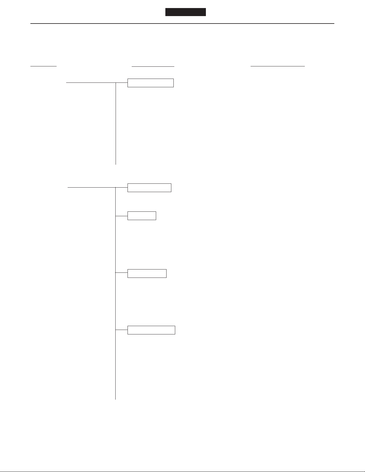
TROUBLESHOOTING
(ENGINE)
Symptom Possible cause Remedy/Prevention
Engine overheating Coolant
● Insufficient coolant ........................................Add coolant
`
● Defective thermostat ..................................... Replace the thermostat
● Overflow of coolant due to leakage of ..........Repair
exhaust into cooling system
● Damaged rubber hose ..................................Replace rubber hose
● Coolant leakage due to deteriorated.............Replace rubber hose
rubber hose
● Coolant leakage from coolant pump .............Replace the coolant pump
● Coolant leakage from rubber hose ...............Retighten or replace clamp
connection
● Coolant leakage from cylinder head ............. Replace gasket
gasket
Coolant pump
● Bearing seizure .............................................Replace
● Damaged (corroded) vane ............................Replace vane
Radiator
● Clogged with rust and scale..........................Clean radiator
● Clogged with iron oxide due to leakage ........ Clean coolant passage and
of exhaust into cooling system correct exhaust leakage
● Coolant leakage ............................................Repair or replace radiator
● Damaged cooling fan .................................... Replace cooling fan
● Clogged radiator core due to mud or ............Clean radiator
other debris
● Defective radiator cap pressure valve ..........Replace radiator cap
Abnormal combustion
● Incorrect injection timing ...............................Adjust injection timing
● Reduced injection pressure .......................... Adjust injection pressure
● Poor fuel........................................................Use good quality fuel
● Poor nozzle spray .........................................Adjust or replace nozzle
● Unsatisfactory automatic timer......................Repair or replace timer
advance angle
Page 3

1 page 1
ENGINE 3-1-3Models J08C-TP and J08C-TR
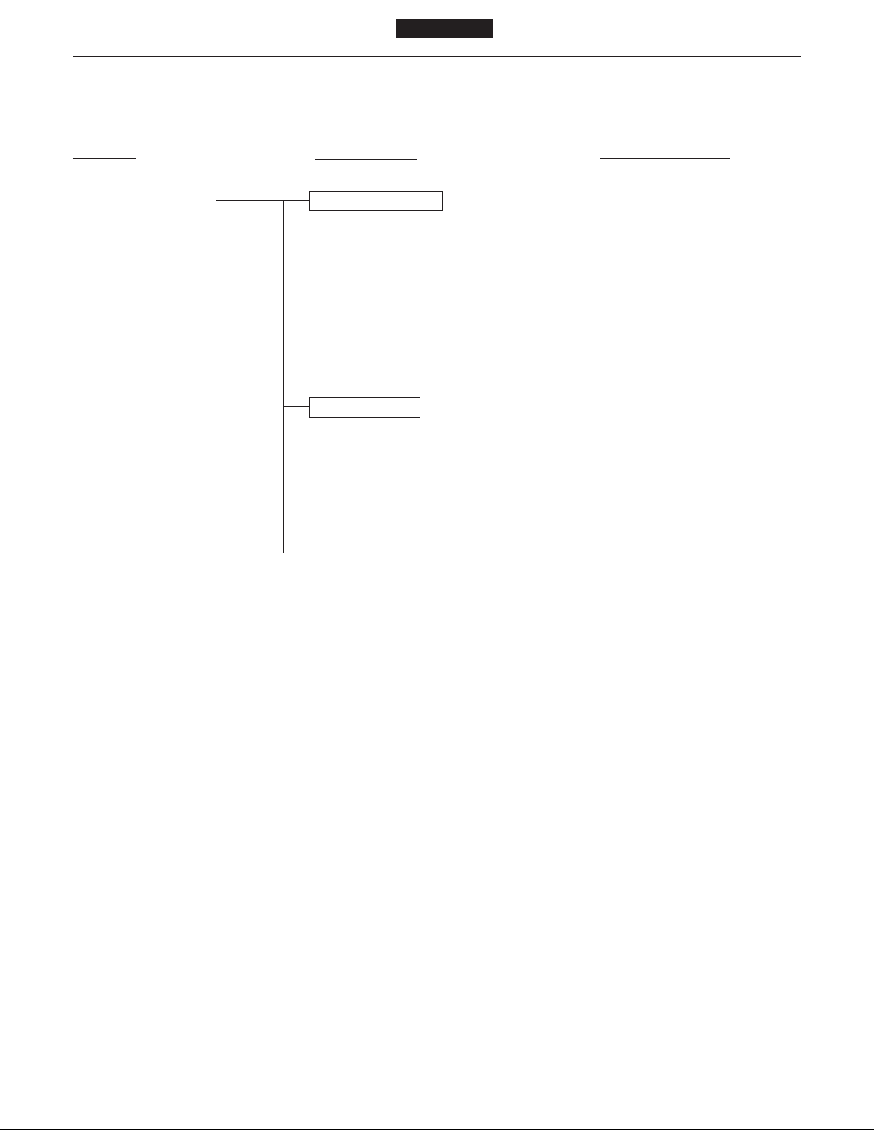
Symptom Possible cause Remedy/Prevention
Engine overheating Other problems
● Defective or deteriorated engine oil ..............Change engine oil
● Unsatisfactory operation of oil pump ............Replace or repair
● Insufficient oil ................................................Add oil
● Brake drag .................................................... Adjust
Severe operating conditions
● Lugging the engine ....................................... Operate engine properly
Excessive oil consumption Pistons, cylinder liners and piston rings
● Wear of piston rings and cylinder liner..........Replace piston rings and
● Worn, sticking or broken piston rings............Replace piston rings and
● Insufficient tension on piston rings................Replace piston rings and
● Unsatisfactory break-in of piston rings..........Replace piston rings and
● Unsuitable oil (viscosity too low) ................... Change oil as required and
●
Incorrectly fitted piston rings (upside down)..
● Gaps of piston rings in line with each other ..Reassemble piston rings
Valves and valve guides
● Worn valve stem ...........................................Replace valve and valve guide
● Worn valve guide ..........................................Replace valve guide
● Incorrectly fitted valve stem seal...................Replace the stem seal
● Excessive lubricant on rocker arm ................ Check clearance of rocker arm
cylinder liner
cylinder liner
cylinder liner
cylinder liner
replace piston rings and
cylinder liner
Replace piston rings
and shaft
Excess oil feed
● Defective oil level gauge ............................... Replace oil level gauge
● Oil level too high ........................................... Drain excess oil
Page 4
1 page 1
3-1-4 ENGINE
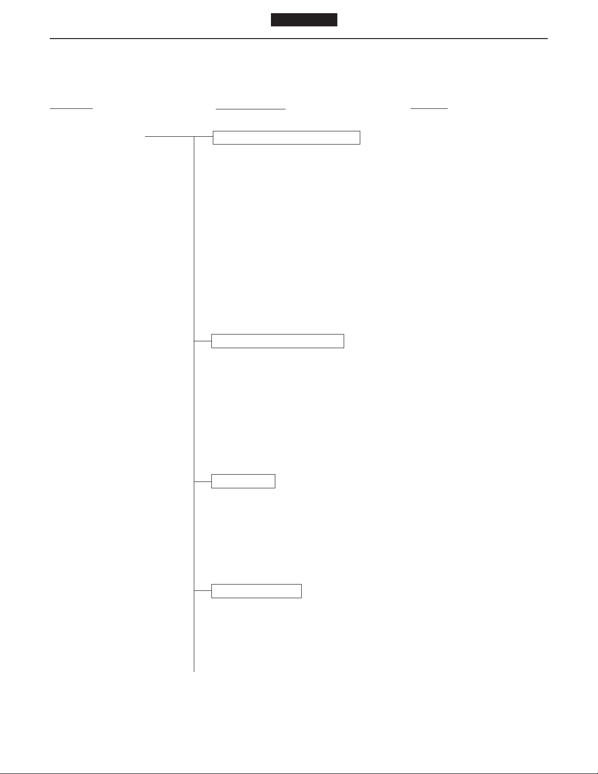
Symptom Possible cause Remedy/Prevention
Excessive oil consumption Oil leakage from miscellaneous parts
● Oil leakage from oil seal................................Replace oil seal
● Cracks or blowhole in cylinder block.............Replace cylinder block
● Oil leakage from connections of oil lines ......Tighten connections of oil lines
● Oil leakage from oil cooler ............................ Replace oil cooler
● Oil leakage from oil pan gasket ....................Replace oil pan gasket
● Oil leakage from O-ring.................................Replace O-ring
●
Models J08C-TP and J08C-TR
Other problems
Overcooled engine ........................................
(low temperature wear)
Warm up engine before moving
vehicle
Check cooling system
NOTE: If oil consumption is excessive, the problems above will occur. Complaints from the
customer are often related to such problems.
1. White smoke is emitted continuously when the engine is run at high speed.
2. White smoke is emitted only immediately after the engine speed is abruptly raised
when idling.
3. The tail pipe is blackened with oil.
4. Oil leaks from the flanges of the exhaust manifold.
5. Lack of power.
6. Excessive blow-by gas.
Piston seizure Pistons, cylinder liners and piston rings
● Incorrect clearance between piston ..............Replace piston, piston rings
and cylinder liner and cylinder liner
● Unsatisfactory installation of piston pin.........Replace piston, piston rings,
cylinder liner and piston pin as
required
● Broken piston ring ......................................... Replace piston, piston rings
and cylinder liner
● Difference in expansion due to use of...........Replace piston, piston rings
wrong piston and cylinder liner
Page 5

1 page 1
ENGINE 3-1-5Models J08C-TP and J08C-TR
Symptom Possible cause Remedy/Prevention
Piston seizure Coolant
● Reduction in capacity of coolant pump .........Replace the coolant pump
(due to vane corrosion)
● Leakage of coolant........................................Repair
● Insufficient coolant ........................................Add coolant
● Dirty coolant ..................................................Clean and replace coolant
● Defective radiator..........................................Repair or replace the radiator
(coolant leakage, clogging)
● Defective rubber hose (leakage)...................Replace rubber hose
● Defective thermostat ..................................... Replace the thermostat
● Leakage of exhaust into cooling system ....... Repair
Operation
● Abrupt stoppage of engine after running ......Operate engine properly
at high speed
● Hill climbing using unsuitable gear ...............Select suitable gear
Oil
● Insufficient oil ................................................Add oil
● Dirty oil ..........................................................Change oil
● Poor quality oil .............................................. Replace with proper engine oil
● High oil temperature......................................Repair
● Low oil pressure............................................Repair
● Defective oil pump ........................................ Repair oil pump
● Reduced performance due to worn ..............Replace oil pump
oil pump
● Suction strainer sucking air...........................Add oil and/or repair strainer
Abnormal combustion
● Use of defective fuel ..................................... Change fuel
● Incorrect injection timing ...............................Adjust injection timing
● Engine overheating .......................................See Symptom: “Engine
overheating”
Page 6
1 page 1
3-1-6 ENGINE
Models J08C-TP and J08C-TR
NOTE: If piston seizure occurs, the problems above will occur. Complaints from the customer
are often related to these problems.
1. White smoke is emitted.
2. Lack of power
3. Excessive blow-by gas
Symptom Possible cause Remedy/Prevention
Lack of power Injection pump ............................................Refer to “FUEL INJECTION
PUMP”
Intake
● Clogged air cleaner.......................................Clean element or replace
element
Overheating ...............................................See Symptom: “Engine
overheating”
Fuel and nozzle
● Poor nozzle spray .........................................Adjust or replace injection
nozzle
● Nozzle clogged with carbon .......................... Clean nozzle
● Wear or seizure of nozzle .............................Replace nozzle
● Air in fuel system...........................................Repair and bleed air from fuel
system
● Clogged fuel filter .......................................... Replace element
● Use of poor fuel.............................................Use good quality fuel
Pistons, cylinder liners and piston rings
● Seized or wear of piston ............................... Replace the piston, piston rings
and liner
● Worn or broken piston rings,.........................Replace piston rings, piston
piston and cylinder liner and liner
Page 7

1 page 1
ENGINE 3-1-7Models J08C-TP and J08C-TR
Symptom Possible cause Remedy/Prevention
Lack of power Other problems
● Exhaust brake butterfly valve stuck...............Replace or repair exhaust
in half-open position brake
● Connecting rod bent......................................Replace or repair connecting
rod
● Exhaust pipe or muffler crushed ...................Replace exhaust pipe or
(increased back-pressure) muffler
● Breakage of turbine or blower.......................Refer to TURBOCHARGER in
CHAPTER 51
Leakage of exhaust Head gasket
● Fatigued gasket (aging) ................................Replace gasket
● Damage.........................................................Replace gasket
● Improper installation......................................Replace gasket
Head bolts
● Loose bolts....................................................Tighten bolts
● Elongated bolts .............................................Replace bolts
● Improper tightening torque or........................Tighten properly
tightening sequence
Cylinder block
● Cracking........................................................Replace cylinder block
● Surface distortion .......................................... Repair or replace
● Fretting of cylinder liner insertion portion ...... Replace cylinder block
(insufficient projection of cylinder liner)
Cylinder head
● Cracking........................................................Replace cylinder head
● Surface distortion .......................................... Repair or replace
Cylinder liners
● Cracking........................................................Replace cylinder liner
● Corrosion.......................................................Replace cylinder liner
● Insufficient projection of cylinder liner ........... Replace cylinder liner
Page 8
1 page 1
3-1-8 ENGINE
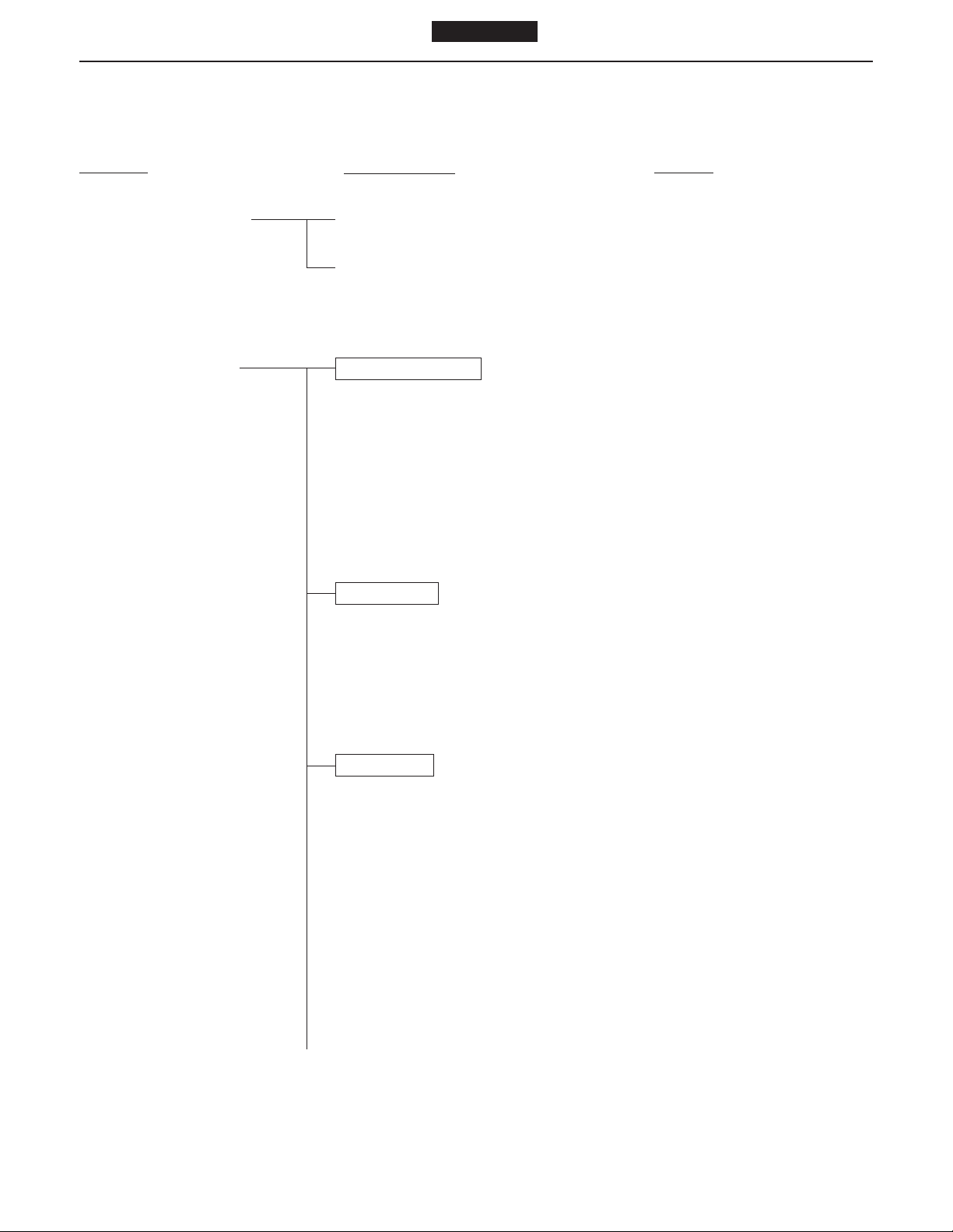
Symptom Possible cause Remedy/Prevention
Leakage of exhaust Other problems
● Incorrect injection timing ...............................Adjust injection timing
Models J08C-TP and J08C-TR
NOTE: If leakage of the exhaust occurs, the problems above will occur. Complaints from the
customer are often related to these problems.
1. Lack of power.
2. The engine overheats.
3. The coolant is discolored.
Difficulty starting engine Electrical system
● Discharged battery........................................Charge battery
● Defective wiring in starter-circuit ................... Repair wiring of starter
● Loose or open-circuit battery cable...............Tighten battery terminal
● Breakdown of starter.....................................Replace starter
● Broken glow plug .......................................... Replace
Injection pump .............................................Refer to “FUEL INJECTION
Air cleaner
● Clogged element...........................................Clean the element or replace
Fuel system
● No fuel in tank ...............................................Supply fuel
● Clogged fuel line ...........................................Clean fuel line
● Air sucked into fuel system through .............. Tighten fuel line connections
fuel line connections
● Clogged fuel filter .......................................... Replace element
● Loose connection in high-pressure line ........ Tighten sleeve nut of high
● Water in fuel..................................................Drain and clean fuel system
connections or replace battery
cable
PUMP”
the element
pressure line
Page 9
1 page 1
ENGINE 3-1-9Models J08C-TP and J08C-TR
Symptom Possible cause Remedy/Prevention
Difficulty starting engine Nozzles
● Seized nozzle................................................Replace nozzle
● Broken or fatigued nozzle spring .................. Replace spring
Oil system
● Oil viscosity too high .....................................Use proper viscosity oil, or
install an oil immersion heater
and warm up oil
Other problems
● Seized piston ................................................ Replace piston, piston rings,
and liner
● Seized bearing .............................................. Replace bearing and crankshaft
● Reduced compression pressure ...................Overhaul engine
● Ring gear damaged or worn ......................... Replace the ring gear and/or
accelerator cable starter pinion
● Improperly adjusted or broken ......................Adjust or replace the
accelerator cable
Rough idling Injection pump ............................................Refer to “FUEL INJECTION
PUMP”
Nozzles
● Uneven injection pressure ............................ Adjust
● Poor nozzle spray .........................................Adjust or replace nozzle
● Carbon deposit on nozzle tip ........................ Remove carbon
● Seized needle valve......................................Replace nozzle
Engine proper
● Improper valve clearance .............................Adjust valve clearance
● Improper contact of valve seat......................Replace or repair valve and
valve seat
● Idling speed too low ......................................Adjust idling speed
● Coolant temperature too low.........................Warm up engine
● Compression pressure of cylinders...............Overhaul engine
markedly different from one another
Page 10
1 page 1
3-1-10 ENGINE
Symptom Possible cause Remedy/Prevention
Rough idling Other problems
● Clogged high pressure injection line ............. Replace line
● Leakage due to improper tightening ............. Tighten sleeve nut
● Improperly adjusted or broken ......................Adjust or replace accelerator
● Engine seizure ..............................................Replace pistons, piston rings
● Incorrect valve timing ....................................Replace camshaft
Models J08C-TP and J08C-TR
of high pressure injection line
accelerator cable cable
and liners
Diesel knock Injection pump...............................................Refer to “FUEL INJECTION
PUMP”
Nozzles
● Incorrect injection pressure...........................Adjust
● Poor nozzle spray .........................................Adjust or replace nozzle
● Sticking of nozzle .......................................... Check and/or replace
● Fatigued or broken nozzle spring .................Replace spring
Fuel system
● Use of poor fuel.............................................Use good quality fuel
● Fuel leakage into combustion chamber ........Adjust nozzles
(during engine starting)
Other problems
● Excessively cooled or heated engine ...........Warm up or cool engine
● Insufficient air intake .....................................Correct
● Insufficient compression pressure ................ Repair
● Compression pressure leaks at .................... Replace head gasket
cylinder head gasket
● Improper valve clearance or valve sticking ... Adjust or repair
● Tappet sticking .............................................. Replace tappet and camshaft
Page 11

1 page 1
ENGINE 3-1-11Models J08C-TP and J08C-TR
Symptom Possible cause Remedy/Prevention
Unusual engine noise Piston
● Wear of piston pin boss or piston pin............Replace piston and/or piston
pin
● Seized, damaged, or worn piston pin ...........Replace piston pin bushing.
bushing
● Worn pistons or cylinder liners......................Replace piston or cylinder liner
● Damaged or seized piston ............................Replace piston and cylinder
liner
● Foreign matter on top surface of the piston ..
Remove foreign matter and
repair or replace piston, cylinder
liner, and/or cylinder head
Valve mechanism
● Incorrect valve clearance .............................. Adjust valve clearance
● Valve cotter out of place................................Replace valve cotter
● Seized valve stem.........................................Replace valve and valve guide
● Broken valve .................................................Replace valve
● Damaged rocker arm support .......................Replace rocker arm support
● Broken valve spring ...................................... Replace valve spring
Bearings seizure
● Insufficient lubricating oil...............................Add oil
● Excessive or insufficient tightening of ........... Retighten to specified torque
bearing housings
● Pits and scratches on bearing surface..........Replace bearing and crankshaft
● Oil film formed on back of bearing ................Replace bearing
● Improper installation of bearing ....................Replace bearing
● Reduction of spread dimension of bearing ... Replace bearing
● Distorted bearing housing ............................. Replace or correct bearing
housing
● Excessive oil clearance.................................Replace bearing
Page 12
1 page 1
3-1-12 ENGINE
Symptom Possible cause Remedy/Prevention
Unusual engine noise Various other parts
● Exhaust gas leakage from exhaust...............Retighten joints
● Loosen or missing intake manifold ...............Retighten or replace
● Intake valve seating is not concentric ...........Replace or correct the valve
● Intake gas leakage........................................Retighten
● Loose cooling fan mounting bolts or .............Tighten the fan and
● Lack of lubricating oil .................................... Lubricate
● Worn timing gear...........................................Replace the timing gear
● Breakage of turbine or blower.......................Refer to TURBOCHARGER in
Models J08C-TP and J08C-TR
pipe joints
flange gasket
and valve seat
Other problems
fan pulley nut crankshaft pulley
(coolant pump, valves, etc.)
CHAPTER 51
NOTE: The items on this page concern unusual engine noise which is due to causes other than
those given for diesel knock.
Page 13
1 page 1
(FUEL INJECTION PUMP)
Symptom Possible cause Remedy
Engine does not start Fuel not reaching injection pump
● Fuel lines clogged or damaged.....................Clean or replace fuel lines
● Fuel filter clogged .........................................Clean or replace the filter
element
● Air in fuel caused by improper ...................... Repair connections
connections of fuel line between
fuel tank and feed pump
● Filter incorporated in inlet side ...................... Remove foreign material
of feed pump clogged
● Faulty feed pump check valve ...................... Repair or replace it
● Feed pump piston spring broken .................. Replace it
● Feed pump push rod or tappet sticking ........Repair or replace it
ENGINE 3-1-13Models J08C-TP and J08C-TR
Fuel reaching injection pump
● Faulty connection of accelerator cable ......... Repair connection
to pump adjusting lever
● Control rack faulty or sticking........................Repair it
● Damaged camshaft bearing..........................Repair it
● Plunger worn or sticking................................Correct or replace it
● Faulty connection of engine .......................... Repair it
stop cable to pump stop lever
Nozzle faulty
● Fuel leakage caused by loosened ................ Inspect and tighten it
nozzle holder
● Low opening pressure of nozzle ...................Adjust it
● Nozzle pressure spring broken .....................Replace it
● Nozzle needle sticking to nozzle body .......... Correct or replace it
Pump out of timing
● Improperly retarded injection timing..............Correct injection timing
● Incorrect timing caused by improper.............Check engine timing and
installation of pump correct it
● Woodruff key for pump camshaft cut off. ......Replace it
● Improper pre-stroke adjustment....................Correct it to obtain specified
injection timing
Page 14
1 page 1
3-1-14 ENGINE
Symptom Possible cause Remedy
Engine starts and stops Fuel lines clogged.........................................Clean or replace fuel lines
Engine has low power Pump out of timing
● Excessive advanced timing...........................Check and correct it
● Excessively retarded timing ..........................Check and correct it
● Defective injection pump overflow valve ....... Repair or replace it
● Feed pressure too low .................................. Repair the feed pump
● Improper accelerator cable adjustment ........Adjust it
Models J08C-TP and J08C-TR
Air in fuel caused by damaged ..................... Repair fuel lines or replace fuel
fuel lines or improper connection of lines and gaskets
fuel lines
resulting in loud knocking
resulting in black smoke
Nozzle faulty
● Fuel leakage from nozzle holder...................Check and repair nozzle holder
● Bad nozzle spray characteristic ....................Repair or replace it
● Loosened adjusting screw in nozzle .............Adjust it
holder, resulting in low opening pressure
● Nozzle pressure spring broken .....................Replace it
Pump faulty
● Fuel leakage from delivery valve .................. Retighten the delivery valve
holder
holder if it is loosened or replace
O-ring if the O-ring is defective
● Defective seat of delivery valve assembly ....Repair or replace it
● Delivery valve spring broken.........................Replace the spring
● Plunger worn.................................................Replace it
● Large spread in fuel delivery.........................Adjust it
● Wear of tappet roller ..................................... Replace the roller
● Camshaft bearing worn or broken.................Replace it
● Improper adjustment of governor..................Adjust it
full load stopper screw
Page 15
1 page 1
Symptom Possible cause Remedy
Excessive smoke Black smoke
● Excessive fuel delivery caused by ................
incorrect adjustment of full load
stopper screw
● Excessively advanced injection timing..........Correct it
● Large spread in fuel delivery.........................Adjust it
● Bad nozzle fuel spray characteristics ...........Check and correct them
White smoke
● Unused after glow system.............................Use it
● Improperly retarded injection timing..............Advance injection timing
● Water in fuel..................................................Check and clean fuel lines
● Glow plug not operating ................................ Check glow plug circuit. Refer
Adjust fuel delivery on test stand
to ELECTRICAL EQUIPMENT
in CHAPTER 20
ENGINE 3-1-15Models J08C-TP and J08C-TR
Low idle speed
Improper adjustment of throttle control knob ..
Correct it
irregular Bad fuel spray characteristic of nozzles. ...... Check and repair them
Incorrect injection timing ............................... Correct it
Incorrect initial tension setting of...................Adjust or replace it
idling spring or the spring broken.
Control rack does not move smoothly...........Disassemble pump and repair it
Large spread in fuel delivery.........................Adjust it
Plunger worn.................................................Replace it
Governor linkage does not move smoothly...Correct it
Defective feed pump .....................................Disassemble and repair it
Engine always runs Accelerator cable sticking .............................Check and correct it
at high speed Governor linkage sticking .............................Disassemble and repair the
governor
Control rack sticking......................................Check and correct it
Loud knocking Improper injection timing...............................Correct it
Bad fuel nozzle spray pattern . .....................Check and correct it
after-dribble
High nozzle opening pressure ......................Adjust the opening pressure
Incorrect fuel deliveries to.............................Readjust the fuel deliveries
some nozzles.
Page 16
1 page 1
Models J08C-TP and J08C-TR
SPECIAL TOOLS
Prior to starting an engine overhaul, it is necessary to have the following.
(1) Lifting parts
Shape Parts No. Parts name No./unit Application
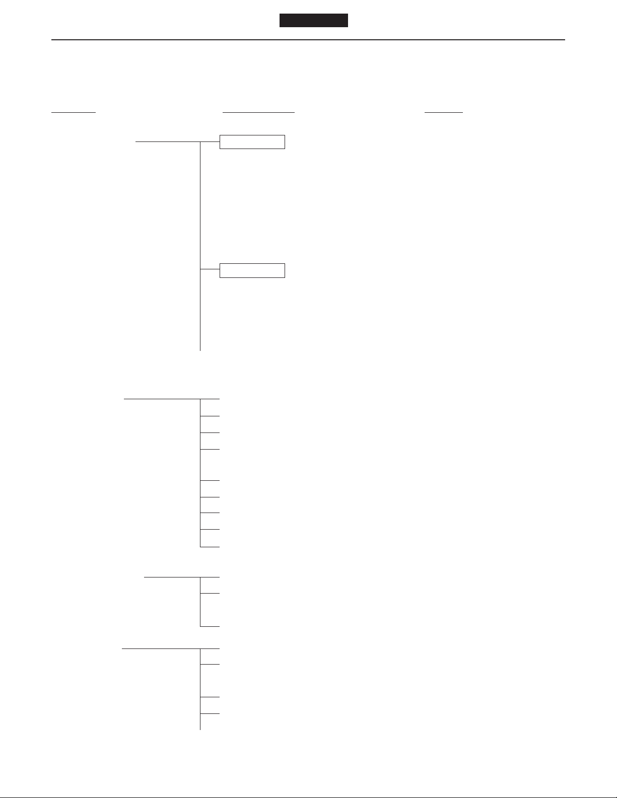
09491 - 1010 Wire cable 1 Lifting engine
SM3-J052
ENGINE 3-2-1
09433 - 1070 Eye bolt 2 Lifting cylinder head
SM3-J048
(2) Related parts of cylinder head
Shape Parts No. Parts name No./unit Application
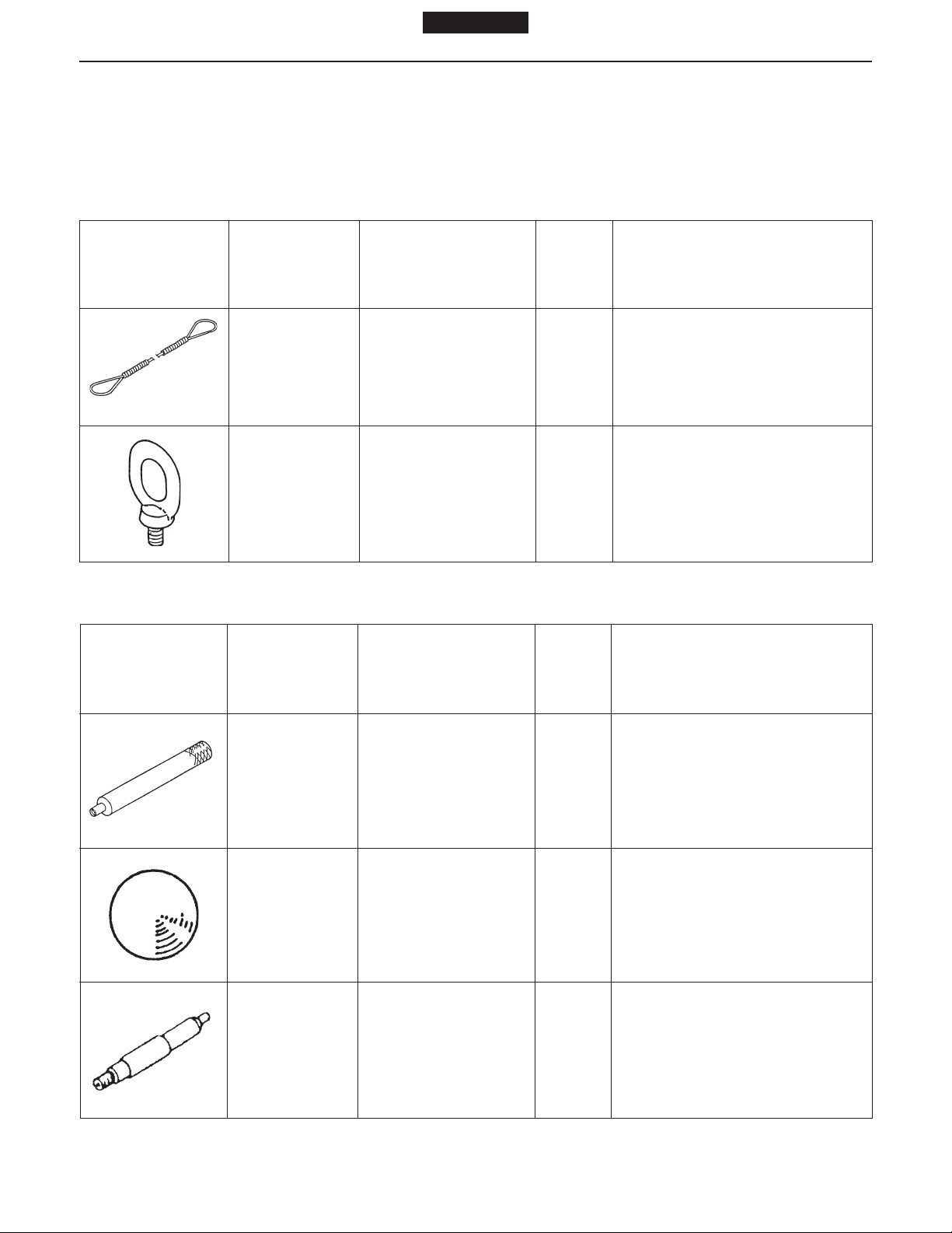
09472 - 1210 Bar 1
SM3-J050
9800-06100 (Steel ball) 1
Caulking nozzle seat
(Use together with 9800 - 06100)
Caulking nozzle seat
(Use together with 09472-1210)
SM3-J054
SM3-J021
09552-1090
Compression gauge
adaptor (for size PF3/8)
1
Measuring compression
Page 17
3-2-2 ENGINE
Shape Parts No. Parts name No./unit Application
SM3-J022
SM3-J055
1 page 1
Models J08C-TP and J08C-TR
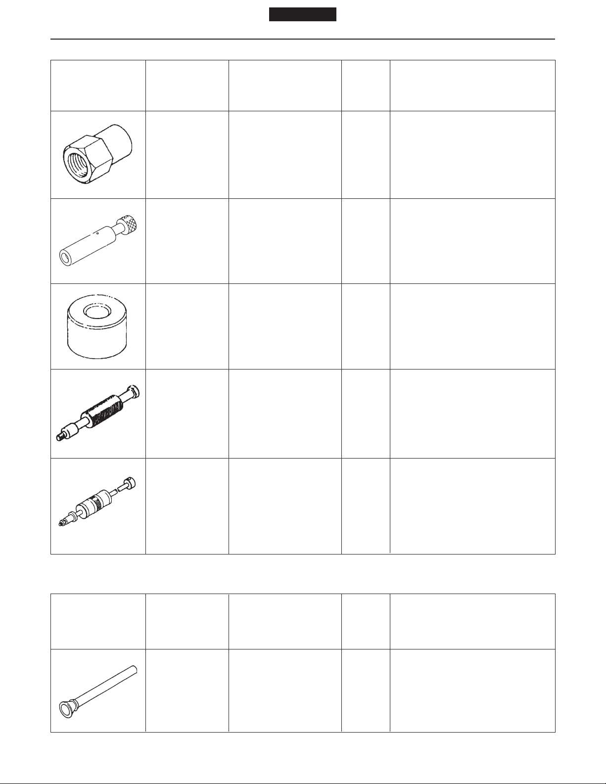
09552 - 1060
Press gauge adaptor 1 Measuring compression
09552 - 1030
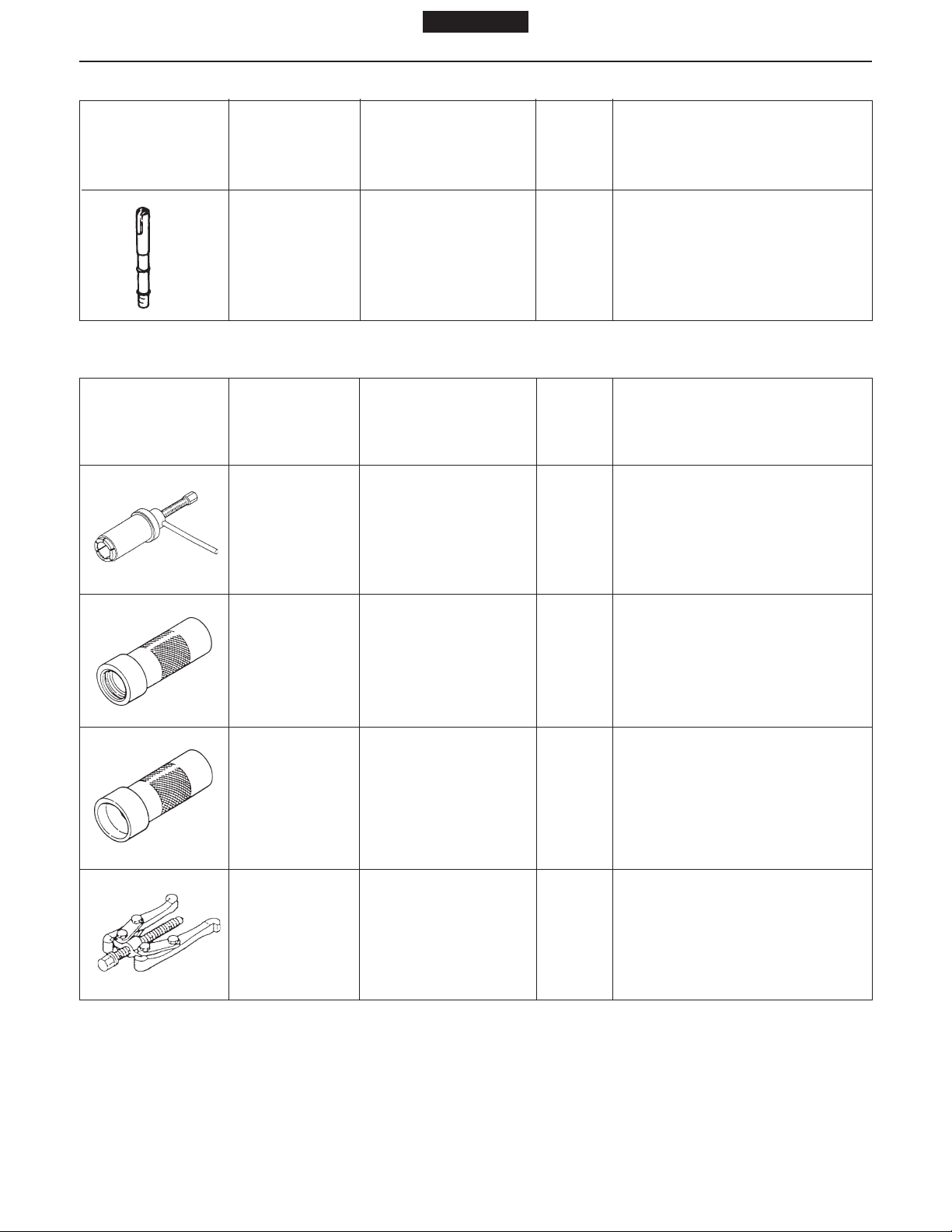
09472 - 2100 Bar 1 Strike-fitting valve stem seal
09471 - 1520 Guide 1 Strike-fitting valve guide
SM3-J051
09420 - 1100 Sliding hammer 1 Removing main idle gear shaft
SM3-J131
09420 - 1442
(Same as tool
for pulling out
injection nozzle)
SM3-J132
(3) Related parts of valve
Removing sub- and cam idle
Sliding hammer 1 gear shafts (Remove the
adaptor from the top before use)
Shape Parts No. Parts name No./unit Application
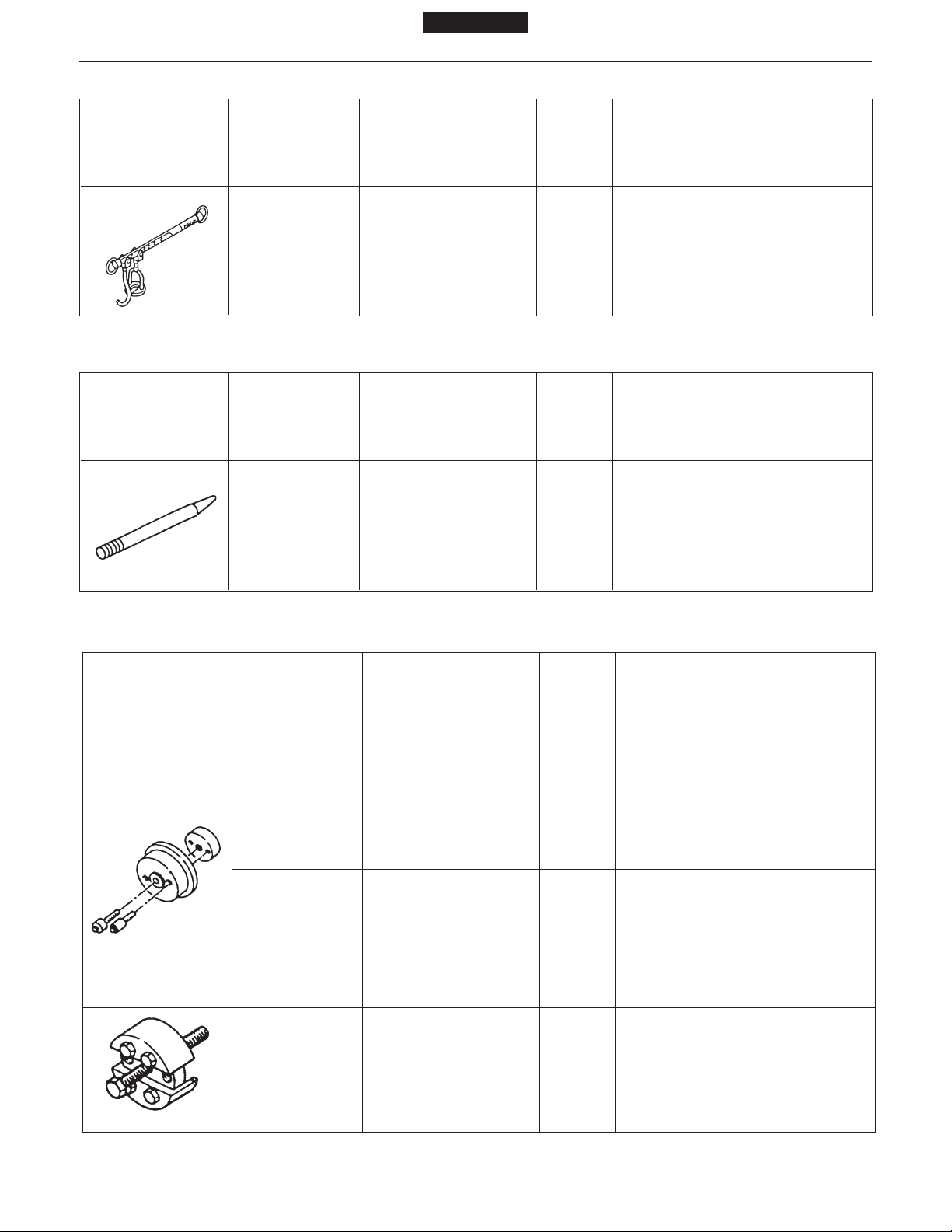
09431 - 1020 Valve wrapping tool 1 Valve wrapping
SM3-J053
Page 18
1 page 1
Models J08C-TP and J08C-TR
Shape Parts No. Parts name No./unit Application
ENGINE 3-2-3
09470 - 1170 Valve spring press 1
SM3-J049
(4) Related parts of flywheel
Shape Parts No. Parts name No./unit Application
09481 - 1340 Guide 1
SM3-J116
(5) Related parts of cylinder block
Removing and installing valve
spring
Removing and installing
flywheel
Shape Parts No. Parts name No./unit Application
09407 - 1030 Oil seal press 1 Press-fitting front oil seal
09407 - 1040 Oil seal press 1 Press-fitting rear oil seal
SM3-J118
09420 - 1731 Oil seal puller 1 Pulling out front oil seal
SM3-J115
Page 19
3-2-4 ENGINE
Shape Parts No. Parts name No./unit Application
SM3-J117
SM3-J148
1 page 1
Models J08C-TP and J08C-TR
09420 - 1742 Oil seal puller 1 Pulling out rear oil seal
09420 - 1720 Cylinder liner puller 1 Pulling out cylinder liner
SM3-J149
SM3-J133
SM3-J146
SM3-J151
09471 - 1490 Guide 1 Insert guide for cylinder liner
09411 - 1300 Socket wrench 1 Rear end plate TORX® bolt
09444 - 1630 Gauge 1 Cooling jet check
9001 - 24262 Check bolt 1 Cooling jet check
SM3-J780
09472 - 1620 Tool 1
Cooling jet check (Fixture for
correction)
Page 20
(6) Related parts of piston
Shape Parts No. Parts name No./unit Application
1 page 1
Models J08C-TP and J08C-TR
ENGINE 3-2-5
SM3-J153
SM3-J145
SM3-J781
09441 - 1320 Piston ring holder
09442 - 1011 Piston ring expander 1
09481-1130 Guide 1
09402-1530 Press sub assembly 1
1
Used when inserting piston into
cylinder block
Removing and installing piston
ring
For replacing the piston pin
bushing
SM3-J782
SM3-J783
9233-10360 Wing nut 1
Page 21
3-2-6 ENGINE
(7) Related parts of connecting rod
Shape Parts No. Parts name No./unit Application
09481 - 1540 Guide 1
SM3-J147
1 page 1
Models J08C-TP and J08C-TR
09402-1540
SM3-J152
9191 - 08252 Bolt 1
SM3-J150
(8) Related parts of filter
Shape Parts No. Parts name No./unit Application
09553 - 1021 Oil filter wrench 1 Removing and installing oil filter
Press sub assembly 1
Replacing connecting rod
bushing
SM3-J784
SM3-J785
09553 - 1010
Fuel filter wrench 1
Removing and installing fuel filter
Page 22
(9) Related parts of injection pump
Shape Parts No. Parts name No./unit Application
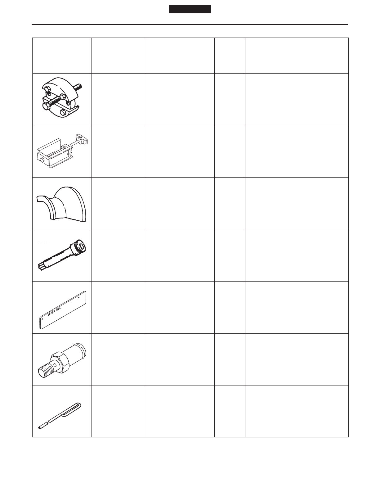
09511 - 2500 Wrench 1 Injection pump coupling
SM3-J200
(10) Related parts for injection nozzle
Shape Parts No. Parts name No./unit Application
1 page 1
Models J08C-TP and J08C-TR
ENGINE 3-2-7
09420 - 1442
(Same as the
parts to remove
idler gear shaft)
SM3-J132
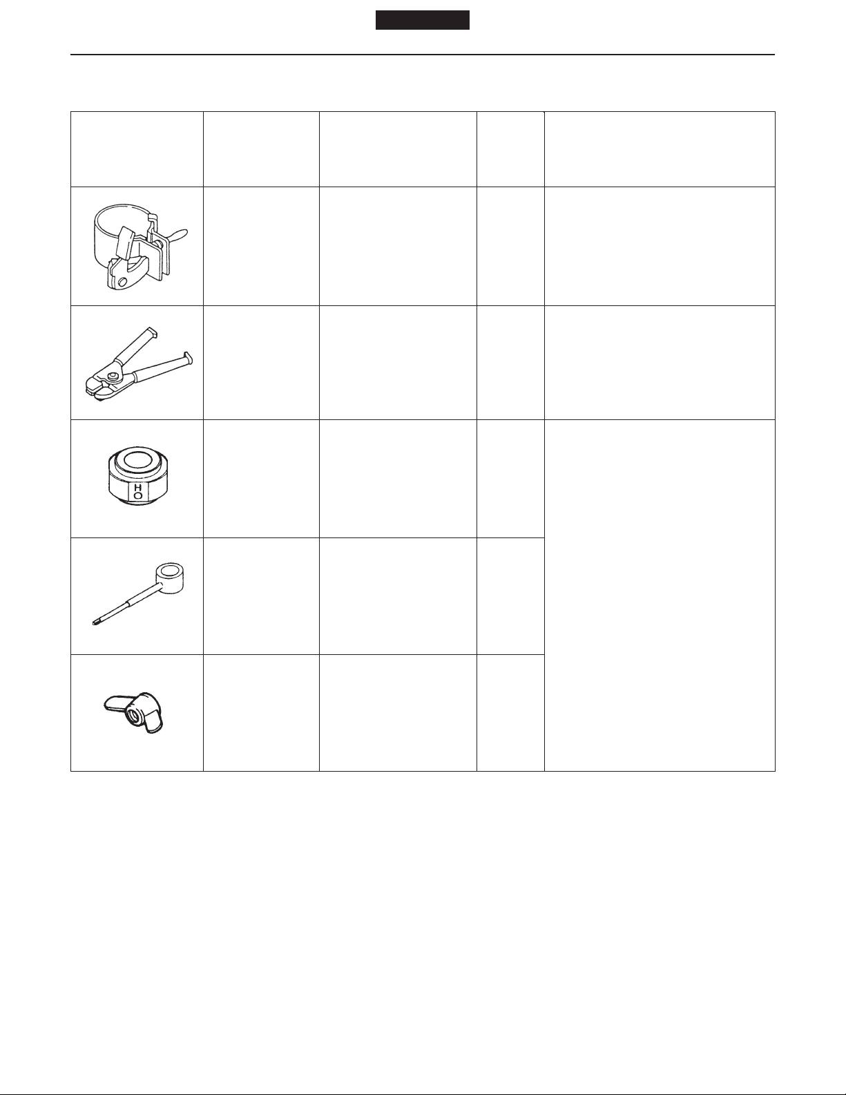
09462 - 1 130 Adaptor 1
SM3-J172
(11) Related parts of coolant pump
Shape Parts No. Parts name No./unit Application
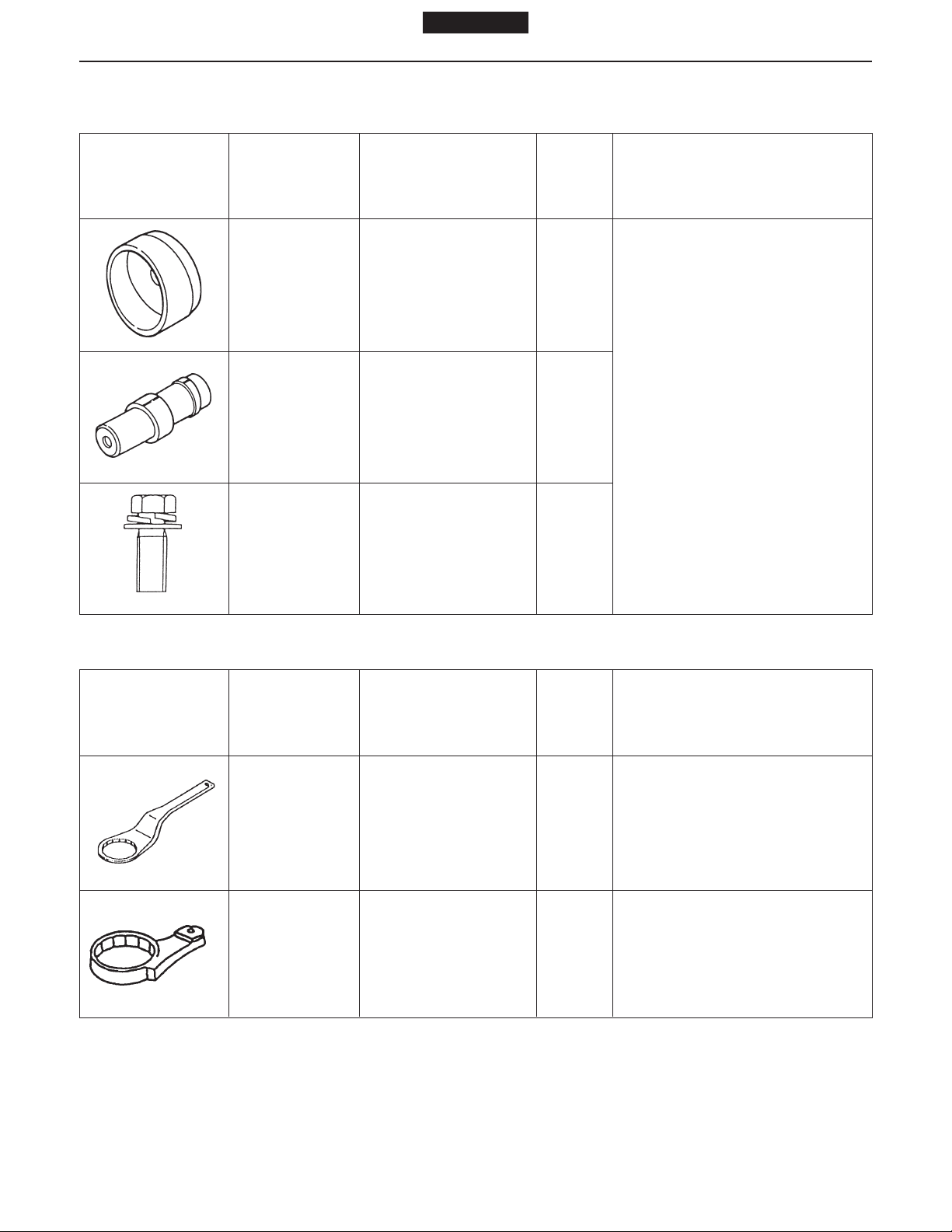
09420 - 1820 Puller assembly 1 Coolant pump vane
Sliding hammer 1
Pulling out injection nozzle
(Use together with 09462 - 1 130)
Pulling out injection nozzle
(Use together with 09420 - 1442)
SM3-J786
SM3-J787
09420 - 1810 Puller assembly 1 Coolant pump pulley center
Page 23
1 page 1
3-2-8 ENGINE
Shape Parts No. Parts name No./unit Application
09444 - 1210 Belt tension gauge 1 Adjusting V-belt tension
SM3-J788
(12) Related parts of air compressor
Shape Parts No. Parts name No./unit Application
Models J08C-TP and J08C-TR
SM3-J002
SM3-J003
SM3-J004
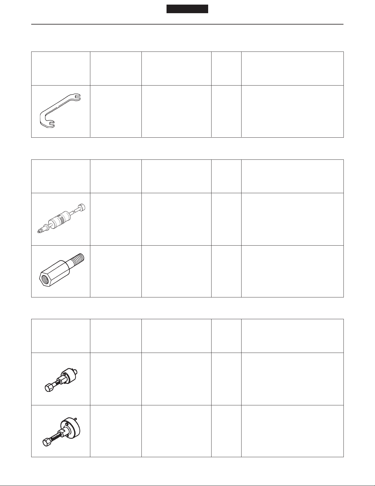
09420 - 1670 Puller assembly 1
09482 - 2220 Press 1
Pulling out air compressor
sleeve
Strike-fitting air compressor
sleeve
09482 - 2230 Press 1
seal
Strike-fitting air compressor oil
09420 - 1680 Puller assembly 1 Pulling out air compressor gear
SM3-J005
Page 24
1 page 1
Models J08C-TP and J08C-TR ENGINE 3-3-1
GENERAL
WARNING
The following items should be observed to prevent
injury to yourself and others when servicing the
engine or vehicle;
● Stop the engine and keep the engine off during
checks and adjustments.
● Place the starter key in the “LOCK” position.
● Leave the engine stop knob pulled out fully.
(For model equipped with manual engine stop
control)
● Place the transmission shift lever in “NEUTRAL”.
● Apply the parking brake firmly.
● Block the wheels.
Fig. 1
SM3-J580
ENGINE OVERHAUL CRITERIA
FACTORS TO DETERMINE THE ENGINE
OVERHAUL
1. LOW COMPRESSION PRESSURE
(1) Before measurement
1. Charge the battery completely.
2. Set the valve clearance to the correct value.
Intake : 0.30 mm (0.0118 in.)
Exhaust : 0.45 mm (0.0177 in.)
(when engine is cold)
NOTE: Refer to page 3-18-4.
3. Idle the engine (to 80 °C {176°F}).
4. While the starter switch is at the LOCK position, disconnect the engine stop motor.
5. Remove all nozzle holders.
NOTE: Refer to page 3-6-3.
6. Remove the air cleaner hose.
Page 25
1 page 1
3-3-2 ENGINE
Models J08C-TP and J08C-TR
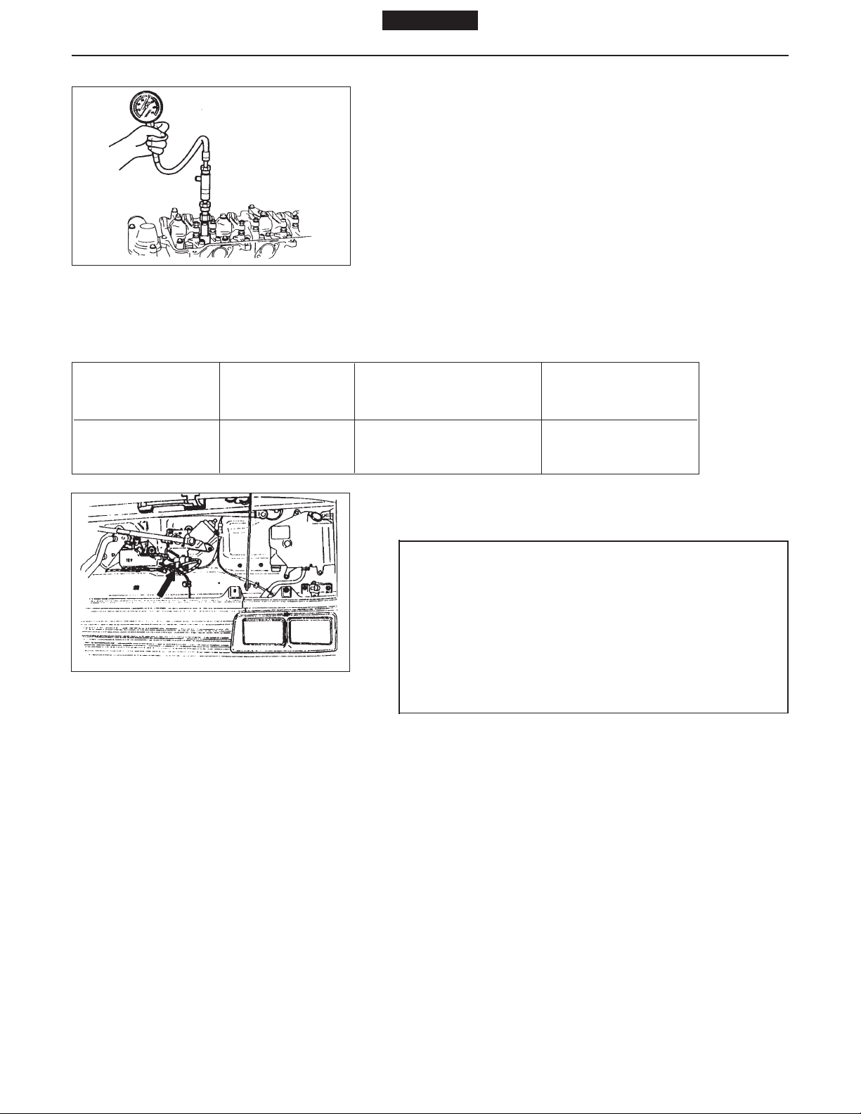
(2) Measurement
1. Insert the gauge adaptor into the nozzle holder hole.
Special tool: Compression gauge adaptor
(09552 - 1090)
(09552 - 1060)
(09552 - 1030)
2. Run the engine with the starter and measure the
compression pressure.
SM3-J581
Fig. 2
NOTE: Do not operate the starter for more than 15 sec-
onds.
3. Measure the compression pressure of each cylinder.
NOTE: Do not allow gas leakage from the seal face.
Unit: kg/cm2 (lb/sq.in.)
Assembly standard Assembly limit Difference among Engine speed
individual cylinders (rpm)
35 - 38 (498-540) 28 (398) Less than 3 (43) 180 - 220
Fig. 3
SM3-J580
(3) After measurement
1. Install the removed parts.
WARNING
Do not connect the electric harness with the engine stop motor while the engine starter key is at
ON position as this may operate the engine stop
motor instantaneously and the link lever of the
engine stop motor and the engine stop lever of the
fuel injection pump will move, resulting in your
fingers caught by the lever.
Page 26
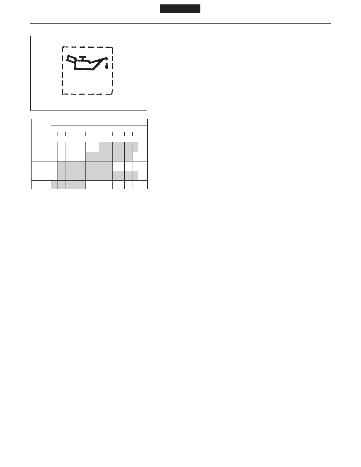
Fig. 4
S.A.E.
GRADE
40
30
20W/20
15W/40
10W/30
Fig. 5
OIL
SM3-J024
ATMOSPHERIC TEMPERATURE
-10 0 32 50 70 90 100 ˚F
-23 -18 0 10 21 32 39 ˚C
1 page 1
Models J08C-TP and J08C-TR ENGINE 3-3-3
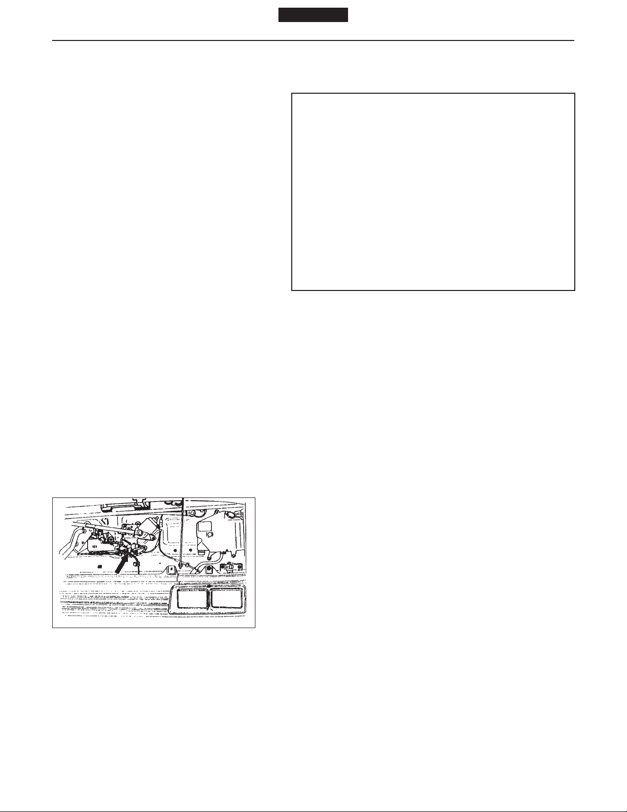
2. DECREASED OIL PRESSURE
Check the oil pressure warning lap when the oil and coolant temperature is hot [about 80°C (176°F)].
a. If the warning lamp is lit, check the oil level.
b. Check oil deterioration.
If oil quality is poor, replace with a suitable grade oil.
c. Remove the oil pressure switch and install the oil
pressure gauge.
d. Measure the oil pressure at oil temperature 100°C
(212°F).
Standard oil Pressure:
2
At 2,500 (rpm) 5.7 kg/cm
(81.05 lb/sq.in.)
Service Limit:
At idle speed 0.5 kg/cm
2
(7.11 lb/sq.in.)
3. OTHER FACTORS
a. Blow-by gas increases.
b. Engine does not start easily.
c. Engine output decreases.
d. Fuel consumption increases.
e. Engine makes greater noise.
f. Excessive oil consumption.
Page 27
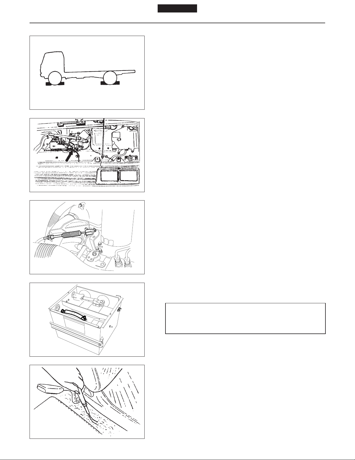
Fig. 1
1 page 1
Models J08C-TP and J08C-TR ENGINE 3-4-1
DISMOUNTING THE ENGINE ASSEMBLY
1. BLOCK THE WHEELS OF THE VEHICLE.
1. Park the vehicle on level ground.
2. Block the wheels.
SM3-J500
2. DISCONNECT THE ENGINE CONTROL AND THE STOP
CABLE.
1. Set the starter switch to the ON position.
2. Disconnect the wires of the engine stop motor at the
connector.
3. Set the starter switch to the LOCK position.
Fig. 2
Fig. 3
Fig. 4
SM3-J580
4. Tilt up the cab.
5. Disconnect the engine control and the stop cable at
the injection pump.
SM3-J582A
3. DISCONNECT THE NEGATIVE TERMINAL OF THE
BATTERY.
WARNING
Always disconnect the battery cable when servicing the engine.
SM3-J583
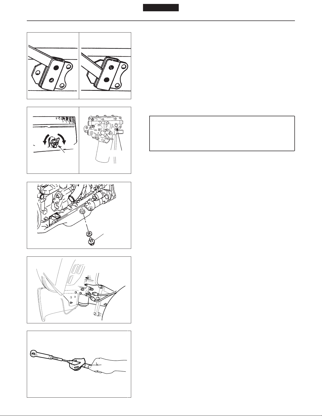
4. DISCONNECT THE PARKING BRAKE CABLE (1).
1. Remove the center console.
2. Disconnect the parking brake cable at the lever.
Fig. 5
SM3-J584
Page 28
1 page 1
Models J08C-TP and J08C-TR3-4-2 ENGINE
OVER-TILTING
POSITION
Fig. 6
OPEN
DRAINING PLUG
Fig. 7
CLOSE
NORMAL POSITION
DRAINING PLUG
SM3-J705B
Fig. 8
5. OVER-TILT THE CAB
NOTE: Refer to CAB in CHAPTER 19.
SM3-J585
6. DRAIN THE COOLANT AND ENGINE OIL.
WARNING
To avoid the danger of burns do not drain the engine oil and coolant while the engine and radiator
are still hot.
1. Drain the coolant from the radiator. (Fig. 7)
NOTE: The coolant can be drained more easily by
removing the filler cap.
Fig. 9
Fig. 10
DRAINING PLUG
SM3-J791
SM3-J587
2. Drain the coolant from the cylinder block. (Fig. 8)
Coolant capacity: 21 L (22.19 US qt)
23 L (24.30 US qt)
(with transmission oil cooler only)
3. Drain the engine oil through the drain plug.
Engine oil capacity: 13.5 L (14.27 US qt)
7. DISCONNECT THE POWER STEERING LINES A T THE
GEAR UNIT.
NOTE: Place a container under the gear unit.
8. DISCONNECT THE PARKING BRAKE CABLE (2).
1. Remove the bracket behind the cab, then pull out
the parking brake cable.
NOTE: Pull out the cable straight and slowly. If pulled out
forcefully, the gasket will crack. Cracked cables
must be replaced with new ones.
Fig. 11
SM3-J589
Page 29
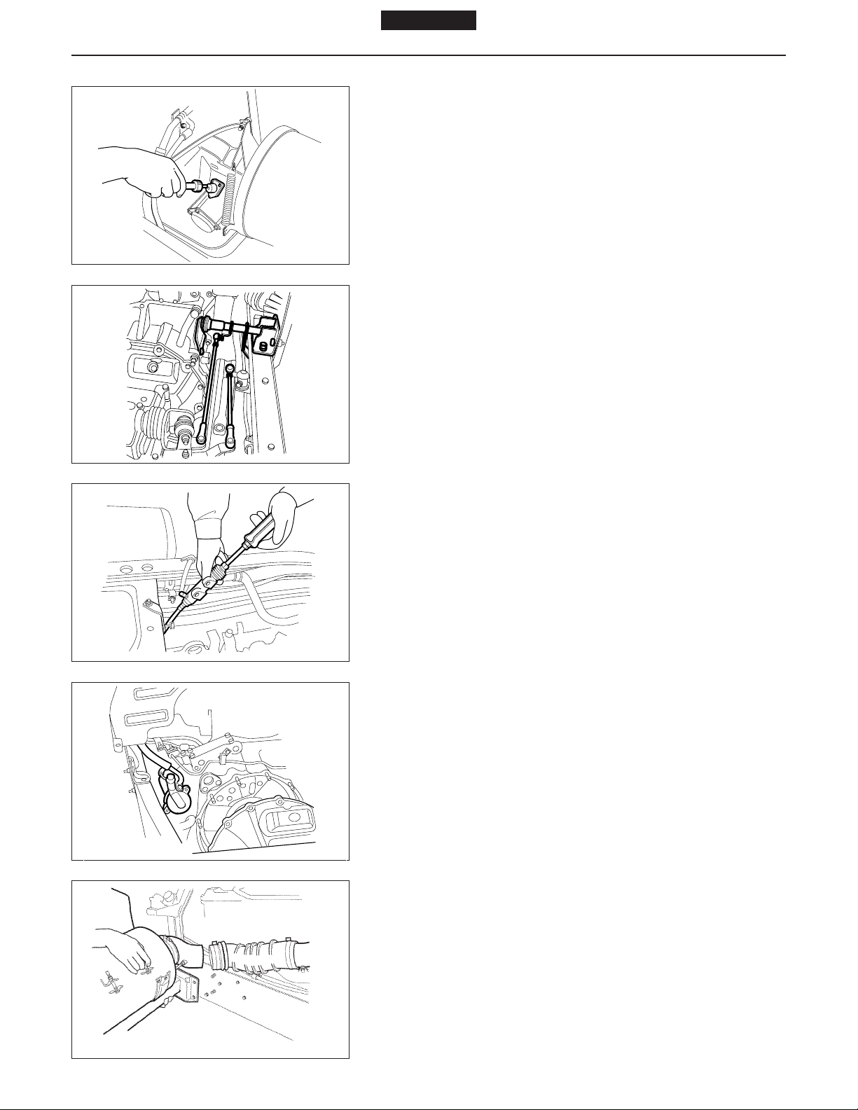
Fig. 12
1 page 1
Models J08C-TP and J08C-TR ENGINE 3-4-3
9. DISCONNECT THE SPEEDOMETER CABLE AT THE
TRANSMISSION.
SM3-J590
10. REMOVE THE TRANSMISSION CONTROL ROD
TOGETHER WITH THE BRACKET A T THE TRANSMISSION.
Fig. 13
Fig. 14
Fig. 15
SM3-J796
11. REMOVE THE CLUTCH SLAVE CYLINDER.
1. Remove the connecting clip of the clutch hose.
2. Remove the return spring and the clevis of the lever.
3. Remove the slave cylinder together with the lines.
SM3-J593
12. DISCONNECT THE POWER STEERING LINES A T THE
PUMP.
NOTE: Be careful of oil leakage from the removed lines
at the gear unit
SM3-J594
13. DISCONNECT THE AIR HOSES WHICH CONNECT THE
AIR CLEANER AND ENGINE.
14. REMOVE THE SPLASH BOARD.
15. REMOVE THE AIR CLEANER TOGETHER WITH THE
BRACKET.
Fig. 16
SM3-J595
Page 30
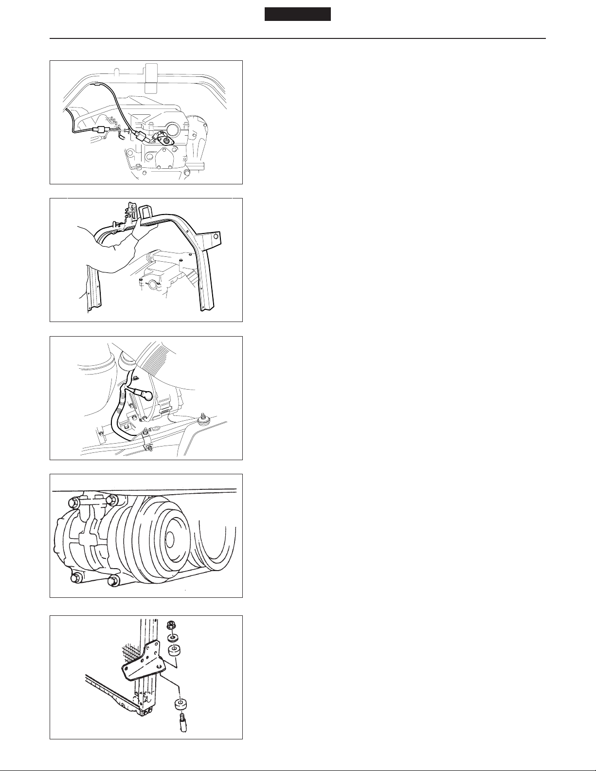
Fig. 17
1 page 1
Models J08C-TP and J08C-TR3-4-4 ENGINE
16. DISCONNECT THE ELECTRICAL WIRES (1).
1. Engine speed sensor
2. Glow plug
3. Rack sensor, pre-stroke actuator
4. Starter terminals B and C and grounding (frame end)
SM3-J596A
17. REMOVE THE REAR CAB MOUNTING BRACKET.
Fig. 18
Fig. 19
Fig. 20
SM3-J597
18. DISCONNECT THE ELECTRICAL WIRES (2).
1. Water temperature sensor (2 parts)
2. Alternator
3. Magnetic clutch of the air conditioner
19. DISCONNECT THE HEATER HOSES.
SM3-J598
20. DISCONNECT THE GAS LINES OF THE AIR CONDITIONER.
1. Use the refrigerant collector to discharge refriger-
ant.
2. Disconnect the gas lines of the air conditioner at the
compressor.
SM3-J599
21. DISCONNECT THE RADIATOR FROM THE FRAME.
1. Disconnect the reservoir hose.
2. Remove the radiator mounting.
Fig. 21
SM3-J600A
Page 31

Fig. 22
1 page 1
Models J08C-TP and J08C-TR ENGINE 3-4-5
22. REMOVE THE EXHAUST PIPE AND MUFFLER.
SM3-J601A
23. REMOVE THE PROPELLER SHAFT.
1. Remove the center bearing support.
NOTE: Attach a hoist to the propeller shaft.
2. Loosen the flange, then remove the propeller shaft.
Fig. 23
Fig. 24
SM3-J602
SM3-J502
24. REMOVE THE TRANSMISSION.
1. Place a jack under the bottom of the flywheel hous-
ing.
2. Place a transmission jack under the transmission.
WARNING
The engine must be suspended with a hoist until
completion of disassembly of the transmission
assembly.
3. Remove the mounting bolt of the mounting rubber
behind the transmission.
4. Remove the mounting bolt of the transmission at the
clutch housing, then remove the transmission.
NOTE: Jack up and align the transmission with the en-
gine, then pull the transmission straight out.
Page 32

Fig. 25
1 page 1
Models J08C-TP and J08C-TR3-4-6 ENGINE
25. REMOVE THE ENGINE ASSEMBLY.
1. Attach hoists to the engine hangers at the front and
rear ends of the engine, and lift slightly.
2. Remove the engine mounting at the frame.
3. Remove the engine assembly together with the ra-
diator and inter cooler.
4. Mount the engine assembly on a work stand.
SM3-J503
26. REMOVE THE RADIATOR AND INTER COOLER.
1. Loosen the tightening band of the fan shroud.
2. Disconnect the radiator hoses and inter cooler hoses
at the engine.
3. Remove the radiator and inter cooler.
NOTE: Attach a hoist to the radiator.
Fig. 26
Fig. 27
SM3-J604
27. REMOVE THE CLUTCH COVER AND CLUTCH DISC.
NOTE: Refer to CLUTCH in CHAPTER 5.
SM3-J746
28. REMOVE THE AIR CONDITIONER COMPRESSOR.
1. Loosen the tension pulley, then remove the V-belt.
2. Remove the air conditioner compressor.
Page 33

Fig. 1
1 page 1
Models J08C-TP and J08C-TR ENGINE 3-5-1
REMOVAL OF THE ENGINE COMPONENT PARTS
1. PREPARATION
1. Loosen the coolant drain cock of the oil cooler, then
discharge coolant.
2. Loosen the oil drain plug of the oil filter, then dis-
charge oil.
SM3-J606
3. Clean the engine assembly.
a. Cover openings with tape.
b. Clean the engine assembly with a steam cleaner.
NOTE: Do not apply steam directly to the electrical com-
ponents. (Alternator, starter, etc.)
4. Mount the engine assembly on a work stand.
Fig. 2
Fig. 3
Fig. 4
SM3-J504
2. REMOVE THE POWER STEERING OIL PUMP.
SM3-J607
3. REMOVE THE STARTER.
1. Put alignment marks on the harness and the starter
terminal, then remove the harness.
2. Remove the starter from the engine.
SM3-J608
4. REMOVE THE FUEL FILTER AND FUEL LINES.
Remove the fuel lines, oil lines and fuel leakage lines.
NOTE:
● Cover openings to prevent foreign matter from enter-
ing.
● Refer to page 3-12-1.
Fig. 5
SM3-J609
Page 34

1 page 1
3-5-2 ENGINE
Fig. 6
Models J08C-TP and J08C-TR
5. REMOVE THE INTAKE MANIFOLD.
SM3-J613
6. REMOVE THE INJECTION PUMP.
1. Remove the through bolt of the coupling.
Fig. 7
Fig. 8
Fig. 9
Fig. 10
SM3-J610A
SM3-J611C
SM3-J612
SM3-J614
2. Use the following special tool and loosen the adjust-
ing bolt.
Special tool: Injection pump coupling wrench
(09511 - 2500)
3. Remove the mounting bolt of the injection pump, then
remove the pump assembly.
NOTE: Cover openings to prevent foreign matter from
entering.
7. REMOVE THE AIR COMPRESSOR.
1. Remove the oil lines, refrigerant lines and air lines.
2. Remove the air compressor.
3. Remove the mounting bolt of the air compressor, then
remove the air compressor.
NOTE: Do not remove the air compressor forcefully. The
spigot may be damaged, or oil leakage may occur due to removal of liquid gasket between the
flywheel housing and the rear end plate.
Page 35

Fig. 11
1 page 1
Models J08C-TP and J08C-TR ENGINE 3-5-3
8. REMOVE THE TURBOCHARGER.
NOTE: Refer to TURBOCHARGER in CHAPTER 51.
SM3-J615
9. REMOVE THE OIL FILTER AND OIL COOLER.
1. Remove the oil lines.
2. Remove the oil filter.
Special tool: Oil filter wrench (09553 - 1021)
3. Remove the oil cooler.
Fig. 12
Fig. 13
Fig. 14
SM3-J616
10. REMOVE THE EXHAUST MANIFOLD.
SM3-J617
11. REMOVE THE V-BELT AND THE ALTERNATOR.
1. Loosen the V-belt adjustment bolt.
2. Loosen the through bolt.
3. Remove the V-belt, then remove the alternator.
SM3-J619A
12. REMOVE THE FAN CLUTCH TOGETHER WITH THE
COOLING FAN.
Fig. 15
SM3-J620
Page 36

1 page 1
3-5-4 ENGINE
Fig. 16
Models J08C-TP and J08C-TR
13. REMOVE THE THERMOSTAT CASE.
SM3-J621
14. REMOVE THE COOLANT PUMP.
Fig. 17
SM3-J622
Page 37

1 page 1
Models J08C-TP and J08C-TR ENGINE 3-6-1
CAMSHAFT HOUSING AND CYLINDER HEAD
1
2
7
12
3
4
13
16
8
9
5
6
14
11
10
15
Fig. 1
17
30
31
21
22
23
24
25
26
27
32
33
28
29
18
18
20
19
SM3-J264A
Page 38

34
1 page 1
Models J08C-TP and J08C-TR3-6-2 ENGINE
35
Fig. 2
1. Oil filler cap
2. Cylinder head cover
3. Silent block
4. Spacer
5. Head cover gasket
6. Valve rocker shaft
7. Lock nut
8. Valve rocker arm
9. Adjusting screw
10. Nozzle clamp
11. Valve rocker support
12. Camshaft bearing
13. Camshaft bearing cap
14. Camshaft
15. Camshaft drive gear
16. Camshaft housing
17. Camshaft housing gasket
18. Idler gear thrust plate
19. Camshaft idler gear
20. Idler gear shaft
21. Cross head
22. Valve spring retainer
23. Valve spring seat upper
24. Valve spring outer
25. Valve spring inner
26. Valve stem seal
27. Valve spring seat lower
28. Cross head adjusting screw
29. Lock nut
30. Cylinder head
31. Cylinder head gasket
32. Valve seat
33. Valve
34. Valve stem guide
35. Nozzle seat
SM3-J265
Page 39

Fig. 3
NOZZLE CLAMP BOLT
SM3-J623
LEAKAGE PIPE
1 page 1
Models J08C-TP and J08C-TR ENGINE 3-6-3
DISMOUNTING
1. REMOVE THE CYLINDER HEAD COVER.
NOTE: Clean all dust from around the cylinder head
cover before removing it to prevent foreign particles from getting in.
2. REMOVE THE INJECTION NOZZLE.
1. Remove the leakage pipe.
2. Loosen the injection pipe nut.
3. Remove the injection pipe seal mounting bolts. Re-
move the injection pipe seal together with the injection pipe out of the cam housing.
4. Remove the nozzle clamp bolt.
Fig. 4
Fig. 5
CAM HOUSING
O-RING
NOZZLE HOLDER
ASSEMBLY
SM3-J178
5. Pull out the nozzle holder assembly, avoiding any
interference.
NOTE: If difficult, use a special tool, sliding hammer
(09420 - 1442), for easier removal.
6. Remove the O-ring.
NOTE: Replace the O-ring with a new one.
SM3-J624
Page 40

Fig. 6
LOCK NUT
ADJUSTING
SCREW
ROCKER ARM SUPPORT
124 675 3
1 page 1
Models J08C-TP and J08C-TR3-6-4 ENGINE
3. LOOSEN THE VALVE CLEARANCE ADJUSTING
SCREW.
1. Loosen the lock nut at the top of the rocker arm, then
wind up the adjusting screw completely.
NOTE: If the adjusting screw is left unwound, the rocker
shaft may bend when the rocker arm support is
loosened.
SM3-J056
4. REMOVE THE ROCKER ARM ASSEMBLY.
1. Remove the rocker arm support bolt in the order as
shown in the figure.
NOTE: When the rocker arm assembly is removed, the
rocker arm and rocker arm support tend to come
off the rocker shaft. Be careful in handling.
Fig. 7
Fig. 8
Fig. 9
SM3-J266
5. REMOVE THE CAMSHAFT.
1. Remove the cam bearing cap bolt.
2. Remove the camshaft together with the gear.
NOTE: Be extremely careful not to drop any part into the
interior of the engine.
SM3-J625
6. REMOVE THE CAM HOUSING.
1. Remove the cam housing bolts.
2. Tap and remove the cam housing with a plastic ham-
mer.
SM3-J626
7. REMOVE THE CYLINDER HEAD BOLTS.
Remove the cylinder head bolts in the order as shown in the figure.
Fig. 10
SM3-J276B
Page 41

Fig. 11
SM3-J627
1 page 1
Models J08C-TP and J08C-TR ENGINE 3-6-5
8. LIFT AND REMOVE THE CYLINDER HEAD FROM THE
CYLINDER BLOCK.
Special tool: Eye bolt (09433 - 1070)
NOTE:
● Place a piece of wood between the cylinder head and
table.
● When removing the cylinder head together with the
injection nozzle, avoid contact between the injection
nozzle and a piece of wood.
● Check that there is no oil, water or gas leakage in the
cylinder head gasket if overheated or not.
Page 42

Fig. 12
1 page 1
Models J08C-TP and J08C-TR3-6-6 ENGINE
DISASSEMBLING
REMOVE THE CAM IDLER GEAR.
1. Remove the cam idler gear.
SM3-J628
2. Using the special tool, remove the cam idler gear.
Special tool: Sliding hammer (09420 - 1830)
Fig. 13
Fig. 14
IN
EX
Fig. 15
SM3-J629
SM3-J060
SM3-J061A
DISASSEMBLE THE VALVE SYSTEM.
1. Using the special tool, press fit the valve spring seat
upper, then remove the valve spring retainer.
Special tool: Valve spring press (09470 - 1170)
2. Remove the valve spring seat upper, valve spring
outer and inner.
3. Remove the intake and exhaust valves from the cyl-
inder head.
NOTE:
● Do not remove the valve guide and valve spring seat
lower unless they need to be replaced.
● Align the removed parts in the order of the cylinder
No.
Page 43

Fig. 16
1 page 1
Models J08C-TP and J08C-TR ENGINE 3-6-7
INSPECTION AND REPAIR
CYLINDER HEAD
NOTE:
● Clean the cylinder head thoroughly with a commercial
cleaning agent before inspection.
● Do not damage the lower surface of the cylinder head.
SM3-J062
INSPECT THE CYLINDER HEAD FOR CRACKS.
Check the head surface and intake and exhaust valve
seats, for cracks, using a dye penetrant. If cracks are found,
replace the cylinder head.
Fig. 17
Fig. 18
B
C
D
A
Fig. 19
SM3-J103
CHECK THE CYLINDER HEAD FLATNESS.
1. Check the cylinder head surface for flatness with a
straight edge and a thickness gauge. If the measurements exceed service limits, replace the cylinder
head.
Standard: 0.06 mm (0.0024 in.) or less for longitudinal di-
rection
0.03 mm (0.0012 in.) or less for lateral direc-
SM3-J630
tion
Service limit: 0.20 mm (0.0079 in.)
E’
E
F’
F
G’
G
SM3-J505
A’
C’
D’
B’
2. Check the flatness of the intake and exhaust mani-
folds mounting surfaces.
Standard: 0.06 mm (0.0024 in.) or less for longitudinal di-
rection
0.03 mm (0.0012 in.) or less for lateral direction
Service limit: 0.20 mm (0.0079 in.)
Fig. 20
SM3-J506
Page 44

Fig. 21
Fig. 22
1 page 1
Models J08C-TP and J08C-TR3-6-8 ENGINE
INSPECT THE V AL VE CONT ACT SURF ACES FOR PROPER
CONTACT.
1. Visually check valves for damage, burn marks, car-
bon accumulation, warpage, or cracks in valve heads,
valve stems, and valve stem grooves. Replace valves
which are excessively worn, burnt, warped or
cracked.
SM3-J631
2. Check the valve seating condition.
Lightly apply red lead marking compound to the valve
face. Install the valve with a special tool, tap and
rotate the valve against the seat. Check the valve
face and valve seat for seating. When the red lead
mark is not concentric or even all around the valve
face or seat, correct the valve face or the valve seat.
Special tool: Valve lapping tool (09431 - 1020)
SM3-J104
Fig. 23
Fig. 24
SM3-J507A
SM3-J632
SM3-J507
HAND-LAP THE VALVE AND VALVE SEAT.
Lightly apply lapping compound to the valve face. Install
the valve with a special tool, tap and rotate the valve against
the seat.
NOTE:
● Following completion of hand-lapping, clean off any
lapping compound which has adhered to the valves
and valve seats.
● Following hand-lapping, always recheck the seating
condition.
Special tool: Valve lapping tool (09431 - 1020)
GRIND VALVES
NOTE:
● Grinding of valves should only be performed when
hand-lapping does not result in proper seating.
● Following hand-lapping, always recheck the seating
condition.
WARNING
When grinding, a metal tip may fly off on impact.
Wear safety glasses to protect your eyes.
Page 45

Fig. 25
30˚
INTAKE
1 page 1
Models J08C-TP and J08C-TR ENGINE 3-6-9
Assembly standard:
Valve seat (Intake): 30°00' - 30°35'
Valve face (Intake): 29°30' - 30°00'
Valve seat (Exhaust): 45°00' - 45°30'
Valve face (Exhaust): 44°30' - 45°00'
45˚
EXHAUST
SM3-J097
HAMMER
VALVE
Fig. 26
Fig. 27
C
INTAKE
BLOCK BRASS
VALVE SEAT
ELECTRIC WELDING
APPLIED
GRIND THIS POINT
WITH A GRINDER
SM3-J064
C
EXHAUST
SM3-J065
IF NECESSARY, REPLACE THE VALVE SEAT.
1. Cut three places on the circumference of an un-
wanted valve and weld it to the valve seat.
NOTE: To protect the lower surface of the cylinder head
from welding spatter, be sure to apply grease
before welding.
2. Place a back plate at the top of the valve stem and
strike it with a hammer to remove the valve seat.
NOTE: When striking, a metal tip may fly off on impact.
Wear safety glasses to protect your eyes.
3. Machine the valve seat according to the specified
valve seat dimensions.
Dimensions of the valve seat machining:
Clynder
head side
Valve seat
side
Intake
Unit:mm Unit:in. Unit:mm Unit:in.
A 41-41.016 1.6142-1.6148 39-39.016 1.5355-1.5360
B 9.4-9.6 0.3701-0.3779 8.6-8.8 0.3386-0.3464
C 41.085-41.1 1.6176-1.6181 39.12-39.135 1.5402-1.5407
D 7-7.2 0.2756-0.2834 6-6.2 0.2363-0.2440
Exhaust
Fig. 28
SM3-J066
4. Heat the cylinder head to approx. 80°C (176°F) 90°C (194°F) with hot water . Cool the valve seat with
dry ice for approx. 30 minutes. Hold the seat with
pincers and place it into the heated cylinder head.
The valve seat can be easily made to fit by lightly
hitting it.
WARNING
● Never touch the cooled valve seat with your bear
hands.
● When striking, a metal tip may fly off on impact.
Wear safety glasses to protect your eyes.
● Following valve grinding, always recheck the
seating condition.
Page 46

Fig. 29
Fig. 30
Fig. 31
VALVE
SINK
DIMENSION
90°
VALVE SEAT
CYLINDER
HEAD
VALVE
SM3-J508
SM3-J509
SM3-J510
1 page 1
Models J08C-TP and J08C-TR3-6-10 ENGINE
MEASURE THE VALVE SINK.
Assembly standard:
Intake: 0.55 - 0.85 mm (0.0217 - 0.0334 in.)
Exhaust: 1.05 - 1.35 mm (0.0414 - 0.0531 in.)
Repair limit:
Intake: 1.1 mm (0.0433 in.)
Exhaust: 1.6 mm (0.0630 in.)
NOTE:
● If the valve heads are protruding from cylinder head
surface, the valve heads may hit against the pistons
while the engine is running.
● Following replacement of valve and valve seat, always
recheck the seating condition.
MEASURE THE CLEARANCE BETWEEN THE V AL VE STEM
AND VALVE GUIDE.
1. Measure the outside diameter of the valve stem with
a micrometer. If the value exceeds the service limit,
replace the valve.
Nominal dimension: 7.0 mm (0.2756 in.)
Service limit: Intake 6.92 mm (0.2724 in.)
Exhaust 6.84 mm (0.2693 in.)
2. Calculate the clearance between the valve stem and
valve guide. If the clearance exceeds the service
limit, replace the valve or valve guide.
Nominal dimension:
Intake: 0.023 - 0.058 mm (0.0010 - 0.0022 in.)
Exhaust: 0.037 - 0.067 mm (0.0015 - 0.0026 in.)
Service limit:
Intake: 0.10 mm (0.0039 in.)
Exhaust: 0.12 mm (0.0047 in.)
IF NECESSARY, REPLACE THE VALVE GUIDE.
1. Remove the valve stem seal.
2. Strike the valve guide out with a brass bar and a
hammer.
Fig. 32
WARNING
When striking, a metal tip may fly off on impact.
Wear safety glasses to protect your eyes.
SM3-J51 1
Page 47

1 page 1
Models J08C-TP and J08C-TR ENGINE 3-6-11
Fig. 33
VALVE STEM SEAL
VALVE SPRING SEAT
LOWER
Fig. 34
INTAKE
EXHAUST
VALVE
COAT OIL
SM3-J065
SPECIAL
TOOL
SM3-J068
3. Press fit a new valve guide straight allowing it to protrude as shown in the figure.
NOTE: Apply engine oil lightly to the valve guide outer
circumference before installation.
IF NECESSARY, REPLACE THE VALVE STEM SEAL.
Replace the valve stem seal when the valve guide is replaced or when seal clearance is excessive or the stem
seal has been worn or damaged.
First, install the lower spring seat and valve to the cylinder head (for guide of special tool), then apply engine oil
to the lip of the stem seal and drive the guide with a special tool.
Special tool: Valve stem seal press (09472 - 2100)
WARNING
When striking, a metal tip may fly off on impact.
Wear safety glasses to protect your eyes.
Fig. 35
Fig. 36
NOTE:
B
● After installing the valve stem seal, make sure there
is a gap (A) and (B) as shown in the figure.
A
SM3-J068
● Do not use the special tool if its surface contacting
the valve spring lower seat is deformed.
INSPECT THE VALVE SPRINGS.
1. Check the valve springs for squareness using a
square and a thickness gauge. If a spring is out of
square beyond the service limit, replace it.
Limit: 2.0 mm (0.078 in.) or more
SM3-J098
Page 48

Fig. 37
1 page 1
Models J08C-TP and J08C-TR3-6-12 ENGINE
2. Measure the valve spring tension at a specified length
with the valve spring tester. If the spring force is lower
than the service limit, replace it.
SM3-J098
Outer spring
Inner spring
Fig. 38
Intake
Exhaust
Intake
Exhaust
Free length mm (in.)
Nominal dimension
75.7 (2.980) 75.4 (2.968) 46.8 (1.843) 46.4 (102.23) —
75.7 (2.980) 75.4 (2.968) 46.8 (1.843) 44.2 (97.44) —
64.6 (2.543) 64.3 (2.531) 44.8 (1.764) 21.7 (47.85) —
64.6 (2.543) 64.3 (2.531) 44.8 (1.764) 20.4 (44.98) —
Service limit
Setting height
mm (in.)
Nominal dimension
Setting load kg (lb)
3. Visually check the contact surface of the upper and
lower valve spring seats. Replacement is necessary
if damage such as wear and scratches is excessive.
SM3-J099
INSPECT THE CYLINDER HEAD COOLANT GALLERY FOR
LEAKS.
Close all coolant holes and apply air pressure of about
2
2.5 kg/cm
(36 lb/sq. in.) from one of the coolant holes.
Immerse the cylinder head into the water, then check for
air leakage. If any leakage is found, replace the cylinder
head.
Service limit
Fig. 39
IF NECESSARY, REPLACE THE NOZZLE SLEEVE.
1. Engage a tap to the nozzle sleeve from the bottom
of the cylinder head. Screw in an appropriate bolt,
then strike the bolt head with a hammer and drive
out the nozzle sleeve.
WARNING
When striking, a metal tip may fly off on impact.
SM3-J070SM3-J069
Wear safety glasses to protect your eyes.
Page 49

Fig. 40
SPECIAL
TOOL
SPECIAL
TOOL
CYLINDER HEAD
O-RING
NOZZLE SLEEVE
SM3-J071
NOZZLE
SLEEVE
CYLINDER
HEAD
1 page 1
Models J08C-TP and J08C-TR ENGINE 3-6-13
2. Install an O-ring to the nozzle sleeve insert hole of
the cylinder head. Then apply liquid gasket (Three
Bond No. 121 1 or equivalent) to the bottom of a new
nozzle sleeve, and insert it to the nozzle sleeve insert hole of the cylinder head.
NOTE: Be sure to install a new O-ring. Reused O-rings
may cause water or gas leakage and lead to overheating or cracked heads.
3. Caulk the nozzle sleeve with the special tool.
Special tool: Sleeve bar (09472 - 1210)
Steel ball (9800 - 06100)
Fig. 41
Fig. 42
Fig. 43
Fig. 44
SM3-J072
CYLINDER HEAD
SM3-J100
SM3-J142
SM3-J634
4. Install the injection nozzle to the cylinder head. Then
measure the protrusion of the injection nozzle from
the lower surface of the cylinder head with a vernier
caliper. If the value exceeds the service limit, replace
the injection nozzle.
NOTE: Refer to page 3-12-5.
Assembly standard: 2.25 - 2.75 mm (0.0886 - 0.1082 in.)
Service limit: 2.75 mm (0.1082 in.)
MEASURE THE CLEARANCE BETWEEN THE CAM IDLER
GEAR SHAFT AND CAM IDLER GEAR BUSHING.
1. Measure the outside diameter of the cam idler gear
shaft with a micrometer. If the value exceeds the
service limit, replace the cam idler gear shaft.
Assembly standard: 34.0 mm (1.3386 in.)
Service limit: 33.95 mm (1.3366 in.)
2. Measure the inside diameter of the cam idler gear
bushing with a cylinder gauge. If the value exceeds
the service limit, replace the cam idler gear.
Assembly standard: 34.0 mm (1.339 in.)
Service limit: 34.025 mm (1.340 in.)
3. Calculate the clearance between the idler gear shaft
and idler gear bushing. If the value exceeds the service limit, replace the idler gear shaft and/or idler gear
bushing.
Assembly standard: 0.025 - 0.075 mm (0.0010-0.0029 in.)
Service limit: 0.20 mm (0.0079 in.)
Page 50

Fig. 45
Fig. 46
SM3-J635
SM3-J517
1 page 1
Models J08C-TP and J08C-TR3-6-14 ENGINE
INSPECT THE INTAKE AND EXHAUST MANIFOLDS.
NOTE: Clean the intake and exhaust manifolds with a
commercial cleaning agent before inspection.
1. Check the intake and exhaust manifolds for cracks,
using a dye penetrant. If cracks are found, replace
the manifold.
2. Measure the intake manifold flatness with a straight
edge and a thickness gauge. If the value exceeds
the service limit, replace the intake manifold.
Service limit: 0.2 mm (0.0079 in.)
3. Measure the exhaust manifold flatness with a straight
edge and a thickness gauge. If the value exceeds
the service limit, correct the exhaust manifold by
grinding it to become within 0.14 mm (0.006 in.) per
2 flanges or 0.1 mm (0.004 in.) per flange.
Service limit: 0.2 mm (0.0079 in.)
Fig. 47
Fig. 48
4. Visually check the seal ring of the exhaust manifold
for deformation or wear. Replacement is necessary
if damage such as deformation and wear is
excessive.
SM3-J570
INSPECT THE CAMSHAFT.
1. Visually check the camshaft surface for wear and
scratches.
SM3-J518
Page 51

Fig. 49
SM3-J636
1 page 1
Models J08C-TP and J08C-TR ENGINE 3-6-15
2. Measure the cam height.
Measure the dimensions (A) shown in the figure with
a micrometer. If the value exceeds the service limit,
replace the camshaft.
Nominal dimension A : Intake = 50.0667 ± 0.15 mm
(1.9711 ± 0.0059 in. )
Exhaust = 52.1038 ± 0.15 mm
(2.0513 ± 0.0059 in.)
Service limit: –0.5 mm (–0.0197 in.)
Fig. 50
Fig. 51
Fig. 52
SM3-J519A
SM3-J637
SM3-J638
3. Measure the clearance of camshaft journal.
a. Measure the outside diameter of camshaft journal
with a micrometer. If the value exceeds the service
limit, replace the camshaft.
Nominal dimension: 40.0 mm (1.575 in.)
Service limit: 39.85 mm (1.569 in.)
b. Measure the inside camshaft bearing with a cylinder
gauge. If the value exceeds the service limit, replace
the camshaft bearing.
Nominal dimension: 40.0 mm (1.575 in.)
Service limit: 40.15 mm (1.581 in.)
c. Calculate the clearance from the above measure-
ment. If the clearance is greater than the limit, replace the camshaft or camshaft bearing.
Nominal dimension: 0.020 - 0.063 mm (0.0008 - 0.0024 in.)
Service limit: 0.1 mm (0.0039 in.)
Page 52

Fig. 53
1 page 1
Models J08C-TP and J08C-TR3-6-16 ENGINE
4. Measure the camshaft end play.
Support the camshaft with V -blocks and measure the
run out at the center journal with a dial gauge. If the
value exceeds the service limit, replace it.
Service limit: 0.10 mm (0.0039 in.)
SM3-J639
IF NECESSARY, REPLACE THE CAMSHAFT GEAR.
1. Measure the length of the cam gear bolts, if the length
is A or more, replace with new bolts.
A = 51 mm (2.0078 in.)
2. Make sure there is no dirt or scratch on the cam-
A
shaft gear or tightening surface of the camshaft.
Fig. 54
Fig. 55
Fig. 56
SM3-J080
90˚
SM3-J081 SM3-J082
SM3-J640
3. Apply clean engine oil to the bolt seating and bolt
thread, then tighten the bolt to the specified torque
below.
Tightening torque: 600 kg·cm (43 lb·ft)
4. Retighten them 90° (1/4 turn).
NOTE: When adding torque, never untighten the nuts,
even it they have been overtightened.
INSPECT THE ROCKER ARM ASSEMBLY AND ROCKER
ARM SHAFT.
1. Measure the inside diameter of the rocker arm bush-
ing with a cylinder gauge. If wear exceeds the service limit, replace it.
Nominal dimension: 22.0 mm (0.8661 in.)
Service limit: 22.08 mm (0.8693 in.)
NOTE: When installing a bushing into the rocker arm,
align the bushings with the oil holes of the rocker
arm.
Page 53

Fig. 57
Fig. 58
SM3-J641
SM3-J642
1 page 1
Models J08C-TP and J08C-TR ENGINE 3-6-17
2. Measure the outside diameter of the rocker arm shaft
with a micrometer. If wear exceeds the service limit,
replace the rocker arm.
Nominal dimension: 22.0 mm (0.8661 in.)
Service limit: 21.92 mm (0.8630 in.)
3. Calculate the clearance between the rocker arm
bushing and rocker arm shaft. If the clearance is
greater than the specified limit, replace the rocker
arm bushing.
Assembly standard: 0.03 - 0.101 mm (0.0012 - 0.0039 in.)
Repair limit: 0.15 mm (0.0059 in.)
INSPECT THE ROCKER ARM AND CROSS HEAD.
Visually check the contact between the rocker arm and
cross head. Replace the rocker arm and the cross head
if damage such as wear and scratches is excessive. If
there is only a minimal amount of wear, correct the surface with a resurfacer.
Visually check the adjusting screw thread. Replace the
adjusting screw if damage such as wear and scratches is
excessive.
Page 54

Fig. 59
Fig. 60
SM3-J060
SM3-J643
1 page 1
Models J08C-TP and J08C-TR3-6-18 ENGINE
ASSEMBLING
ASSEMBLE THE VALVE SYSTEM.
NOTE: If parts are reused, install them to their initial
position.
1. Apply engine oil to the intake and exhaust valve
stems. Then insert them to the valve guide installed
to the cylinder head.
2. Install the valve inner and outer springs and valve
spring seat upper.
3. Press fit the valve spring seat upper with the special
tool, then securely fit the valve spring retainer.
Special tool: Valve spring press (09470 - 1022)
ASSEMBLE THE ROCKER ARM ASSEMBLY.
1. Make sure of the correct direction of the rocker arm
support and assemble the rocker arm assembly.
NOTE: Wrong mounting of the rocker arm support results
in seizure of the valve mechanism due to incorrect lubrication.
2. Wind up the adjusting screw of the rocker arm completely.
NOTE: If the adjusting screw is left unwound, the rocker
shaft may bend when the rocker arm support is
tightened.
Fig. 61
Fig. 62
SM3-J644
SM3-J645
INSTALL THE CAM IDLER GEAR.
1. Install the cam idler gear with the snap ring side facing the cylinder head.
2. Install the cam idler gear shaft through a thrust plate,
with the oil filler facing downward.
NOTE: Refer to page 3-6-1.
3. Tighten the idler gear shaft bolt to the specified torque
below.
Tightening torque: 1,100 kg·cm (80 lb·ft)
MEASURE THE CAM IDLER GEAR END PLAY.
After installing the cam idler gear, measure the clearance
between the cam idler gear and thrust bearing with a dial
gauge. If the clearance exceeds the service limit, replace
the thrust bearing.
Nominal clearance: 0.040 - 0.095 mm (0.0016 - 0.0037 in.)
Service limit: 0.30 mm (0.0118 in.)
Page 55

1 page 1
Models J08C-TP and J08C-TR ENGINE 3-6-19
MATCHING SURFACE WITH HEAD END
LIQUID
GASKET
Fig. 63
HEAD
SIDE HOLE
SM3-J037
INSTALL THE IDLER GEAR COVER.
1. Clean the cylinder head mounting surface of the idler
gear cover.
2. Apply liquid gasket to the idler gear cover, then install it to the cylinder head within 20 minutes.
Liquid gasket: ThreeBond No.1207B
Coating width: 1.5 - 2.5 mm (0.06 - 0.10 in.)
NOTE:
● If left more than 20 minutes, clean off the liquid gas-
ket completely and reapply the liquid gasket.
● Refer to page 3-20-1.
Page 56

COOLANT
SEAL RING
Fig. 64
LIQUID GASKET
APPLICATION POINT
LIQUID GASKET
CYLINDER HEAD
CYLINDER
BLOCK
REAR END
PLATE
GEAR CASE
PRINTED SEAL
SM3-J268
PRINT SEAL
LIQUID GASKET
APPLICATION POINT
FLYWHEEL HOUSING
CORRECT
CLEARANCE
TOO POOR
1 page 1
Models J08C-TP and J08C-TR3-6-20 ENGINE
MOUNTING
1. INSTALL THE CYLINDER HEAD GASKET.
NOTE:
● Never reuse the cylinder head gasket as it may cause
engine damage.
● Before installing the cylinder head gasket, remove dirt,
moisture and oil on the cylinder head and cylinder
block surface.
● The coolant seal rings between the bores are easily
damaged. Do not touch them with your hands or other
objects. Make sure that the seal rings are not loose
or damaged.
● Since silicon material is used for the gear case print
seal, make sure that there is no peeling before assembly.
1. Install the cylinder head gasket on the cylinder block
and flywheel housing.
2. Fill the hole at the back of the cylinder head gasket
with liquid gasket.
NOTE: Make sure that the liquid gasket surface is flush
with the cylinder head gasket upper surface.
CLEARANCE
Fig. 65
Fig. 66
A-A SECTION
CLEARANCE
PROTRUDING
A
SM3-J075
2. INSTALL THE CYLINDER HEAD ON THE CYLINDER
BLOCK.
SM3-J627
3. INSTALL THE CYLINDER HEAD BOLT.
1. Preparation
a. Measure the length of the M12 head bolts, if the
length is A or more, replace with new bolts.
A = 126 mm (4.9606 in.)
b. Make sure that no dirt or scratch is on the tightening
surface of the cylinder head bolt.
Fig. 67
SM3-J076A
Page 57

Fig. 68
Fig. 69
PAINT
90˚
90˚
SM3-J078
1 page 1
Models J08C-TP and J08C-TR ENGINE 3-6-21
c. Apply clean engine oil to the bolt surface and bolt
threads.
NOTE: Since the cylinder head bolts are unique to this
engine, do not substitute ordinary bolts.
2. Tighten the cylinder head bolt.
a. Tighten No.1 - No.26 (M12)bolts in
the order shown in the figure to the
specified torque below.
Tightening torque: 600 kg·cm (43 lb.in.)
SM3-J269B
b. Mark the bolts with paint to indicate the same direc-
tions as shown in the figure.
c. Turn No.1 - No.26 bolts 90° (1/4 turn).
d. Retighten them 90° (1/4 turn).
NOTE: Total tightening amounts to 180°. It must not be-
come 200° or more.
e. Make sure that all paint marks face the same direc-
tion.
NOTE: When adding torque, never untighten the nuts,
even if they have been overtightened.
Fig. 70
Fig.71
FLYWHEEL HOUSING
FLYWHEEL
f. Tighten No.27 - No.29 (M10) bolts in
the order shown in the figure to the
specified torque below.
Tightening torque: 600 kg·cm (43 lb·ft)
SM3-J288A
4. INSTALL THE CAM HOUSING.
1. Using the timing line on the flywheel, align No.1 cyl-
inder with the upper dead point.
NOTE: Refer to page 3-18-1.
SM3-J009
Page 58

Fig. 72
ARROW OF
MARK
1 page 1
Models J08C-TP and J08C-TR3-6-22 ENGINE
2. Install the cam housing on the cylinder head.
NOTE: When installing the cam housing, make sure the
cam housing gasket is correctly fitted and is free
of uneven deformation.
SM3-J647
5. ASSEMBLE THE CAMSHAFT.
1. Install the camshaft into the cam housing so that the
arrow stamped on the front of the camshaft gear
faces upward and that the lower line is level.
NOTE: Incorrect installation may damage of the engine.
Fig. 73
Fig. 74
SCALE ETC...
SM3-J083
2. Install the camshaft bearing cap to the cam hous-
ing. Make sure there is no dirt or scratch on the tight-
ening surfaces.
3. Apply clean engine oil to the bolt seating and bolt
thread, then tighten the bolt to the specified torque
below.
Tightening torque: 320 kg·cm (23 lb·ft)
SM3-J648
6. MEASURE THE BACKLASH BETWEEN THE CAMSHAFT GEAR AND CAMSHAFT IDLER GEAR.
Measure the backlash between the camshaft gear and
camshaft idler gear with a dial gauge. If the value exceeds
the service limit, replace the camshaft gear.
Nominal backlash: 0.030 - 0.253 mm (0.0012 - 0.0099 in.)
Service limit: 0.30 mm (0.0118 in.)
Fig. 75
Fig. 76
SM3-J649
7. MEASURE THE CAMSHAFT END PLAY.
Measure the thrust clearance between the camshaft and
camshaft bearing with a dial gauge. If the clearance exceeds the service limit, replace the camshaft.
Nominal clearance: 0.10 - 0.178 mm (0.0040 - 0.007 in.)
Service limit: 0.3 mm (0.0118 in.)
SM3-J650
Page 59

64 21357
SM3-J270
Fig. 77
VALVE SPRING
ROCKER
ARM
LEAKAGE PIPE
NOZZLE CLAMP
BOLT
Fig. 78
INJECTION
PIPE NUT
INJECTION
PIPE SEAL
CAM HOUSING
SM3-J199
1 page 1
Models J08C-TP and J08C-TR ENGINE 3-6-23
8. INSTALL THE ROCKER ARM ASSEMBLY.
1. Install the rocker arm assembly to the cylinder head.
Make sure that the cross head is on each valve.
NOTE: If the cross head is assembled off the valve, the
valve may fall off, resulting in engine damage.
Tightening torque: 480 kg·cm (35 lb·ft)
9. INSTALL THE INJECTION NOZZLE.
1. Install a new O-ring into the groove of the cylinder
head.
2. Make sure that there is no dirt or foreign particles at
the sealing part between the nozzle holder and related parts (O-ring, nozzle sleeve and injection pipe
seal), and connecting part between the nozzle holder
and nut of the injection pipe.
3. Insert the nozzle holder taking care not to contact
the valve spring as shown in the figure.
NOTE: Apply clean engine oil to the O-ring and be care-
ful that the O-ring is not caught.
4. Cover the end of the injection pipe seal with the noz-
zle holder as shown in the figure and tighten the bolts
to fasten the injection pipe seal to the cam housing.
5. Tighten the nut of the injection pipe provisionally.
6. Tighten the nozzle clamp bolt to the specified torque.
Tightening torque: 250 kg·cm (18 lb·ft)
NOTE: After tightening the bolt, make sure that the rocker
arm moves smoothly.
7. Tighten the nut of the injection pipe to the specified
torque.
Tightening torque: 400 kg·cm (28 lb·ft)
8. Install the leakage pipe.
10. ADJUST THE VALVE CLEARANCE.
NOTE: Refer to page 3-18-4.
Fig. 79
SM3-J651
Page 60

1 page 1
Models J08C-TP and J08C-TR3-6-24 ENGINE
CAM HOUSING
Fig. 80
PHASE WHERE
NOT APPLIED
LIQUID
GASKET
COARSE
Fig. 81
HEAD COVER
CYLINDRICAL PLUG
CYLINDRICAL PLUG
PHASE WHERE
TO APPLY LIQUID GASKET
SM3-J085
GOOD
SM3-J086
11. INSTALL THE CYLINDER HEAD COVER
1. Remove the cylindrical plugs at the front and rear
ends of the cam housing. Clean the cylindrical plugs
and the mounting surfaces of the cam housing.
2. Apply liquid gasket to the front and rear half circles
of the cam housing, then install the cylinder plug
within 20 minutes.
Liquid gasket: ThreeBond No.1207B
Coating width: 1.5 - 2.5 mm (0.06 - 0.10 in.)
NOTE:
● If left more than 20 minutes, clean off the liquid gas-
ket completely and reapply the liquid gasket.
● Make sure to wipe off excessive liquid gasket.
● Refer to page 3-20-1.
Fig. 82
HEAD COVER
HEAD
COVER
GASKET
Fig. 83
CAM HOUSING
CAM HOUSING
CLINDRICAL
PLUG
A
BOLT
SILENT BLOCK
SPACER
BOTTOM FACE
OF HEAD COVER
SM3-J087
SM3-J088
3. Apply liquid gasket to plug corner A at the front and
rear ends of the cam housing.
4. Install the cylinder head cover gasket into the gas-
ket groove at the head cover lower surface.
5. Insert the spacer from the head cover lower surface.
6. Install the cylinder head cover to the cam housing.
NOTE: If left more than 20 minutes, clean off the liquid
gasket completely and reapply the liquid gasket.
7. Tighten the mounting bolt of the head cover through
the silent block to the specified torque below and fix
the head cover on the cam housing.
Tightening torque: 250 kg·cm (18 lb·ft)
Page 61

1 page 1
Models J08C-TP and J08C-TR ENGINE 3-7-1
CRANKSHAFT FRONT END, OIL PAN, FLYWHEEL AND
FLYWHEEL HOUSING
7
6
4
3
5
Fig. 1
2
1
2
3
1. Fan pulley spacer
2. Crankshaft pulley
3. Pulley center
4. T orsional damper
5. Seal sub assembly
6. Crankshaft oil seal
7. Oil seal retainer
SM3-J274B
2
5
Fig. 2
4
1
1. Flywheel housing
2. Dust cover
3. Crankshaft oil seal
4. Ring gear
5. Flywheel
SM3-J274A
Page 62

1 page 1
Models J08C-TP and J08C-TR3-7-2 ENGINE
1
2
1. Oil pan gasket
2. Oil pan
3. Soft washer
3
4
4. Drain plug
Fig. 3
SM3-J273A
Page 63

Fig. 4
1 page 1
Models J08C-TP and J08C-TR ENGINE 3-7-3
DISMOUNTING
1. REMOVE THE CRANKSHAFT PULLEY.
SM3-J652
2. REMOVE THE TORSIONAL DAMPER.
Fig. 5
Fig. 6
Fig. 7
SM3-J653
3. REMOVE THE FLYWHEEL HOUSING STAYS.
SM3-J654
4. REMOVE THE OIL PAN AND OIL STRAINER.
SM3-J655
5. REMOVE THE FLYWHEEL ASSEMBLY.
1. Remove the pilot bearing.
Fig. 8
SM3-J520
Page 64

Fig. 9
Fig. 10
PLATE
HOOK
SM3-J656
SM3-J119
1 page 1
Models J08C-TP and J08C-TR3-7-4 ENGINE
2. Remove the flywheel mounting bolts.
3. Hold a copper rod through the starter hole against
the flywheel and drive the rod lightly with a hammer
to remove the flywheel from the crankshaft while
rotating the crankshaft.
WARNING
The flywheel is heavy. When removing, be careful
not to drop it on your feet.
6. REMOVE THE CRANKSHAFT OIL FRONT AND REAR
SEALS.
1. Remove the crankshaft oil seals with the special tool.
Special tool: Oil seal puller (09420 - 1731) for front
(09420 - 1742) for rear
a. Place the plate at the crankshaft end using the crank
pulley mounting bolts (front) or the flywheel mounting bolts (rear).
b. Install the hook to the crankshaft end using the bolt
supplied.
NOTE: Engage the hook with the oil seal notch.
c. Remove the installed bolt in step a.
Fig. 11
Fig. 12
REMOVE AFTER
HOOK INSTALLATION
SM3-J120
CENTER
BOLT
SM3-J121
d. Install the center bolt and tighten it to remove the oil
seal.
7. REMOVE THE DUST COVER.
Fig. 13
SM3-J657
Page 65

Fig. 14
1 page 1
Models J08C-TP and J08C-TR ENGINE 3-7-5
8. REMOVE THE FLYWHEEL HOUSING.
1. Remove the two front mounting bolts of the flywheel
housing.
SM3-J658
2. Remove the rear mounting bolts of the flywheel
housing.
Fig. 15
Fig. 16
3. Remove the flywheel housing by driving it lightly with
a plastic hammer.
SM3-J659
WARNING
The flywheel is heavy. When removing, be careful
not to drop it on your feet.
SM3-J646
9. REMOVE THE OIL SEAL RETAINER.
Fig. 17
SM3-J660
Page 66

Fig. 18
1 page 1
Models J08C-TP and J08C-TR3-7-6 ENGINE
INSPECTION AND REPAIR
INSPECT THE TORSIONAL DAMPER.
NOTE: Clean the torsional damper with a commercial
cleaning agent before inspection.
1. Check if there are any cracks in the damper rubber
section. If the cracks are excessive, replacement is
necessary.
SM3-J661
INSPECT THE FLYWHEEL (MODELS: FD, FE, FF)
1. Check the friction surface for scoring or heat crack-
ing.
If necessary , grind the friction surface or replace the
flywheel.
Grind limit: 1 mm (0.039 in)
Deflection limit: 0.04 mm (0.00157 in.)
NOTE: Do not grind the flywheel over than the limit.
Fig. 19
SM5-089
A
2. Using a straight edge and a feeler gauge, check the
friction surface ware.
If the wear is greater than the sevice limit, replace
the flywheel.
Standard: 0.05 mm (0.0020 in.) or less
Service limit: 1.0 mm (0.039 in.)
INSPECT THE FLYWHEEL (MODEL: SG)
1. Check the friction surface for scoring or heat crack-
ing.
If necessary , grind the friction surface or replace the
flywheel.
Grind limit: 1 mm (0.039 in)
Deflection limit: 0.04 mm (0.00157 in.)
NOTE: Do not grind the flywheel over than the limit.
2. Using a vernier caliper, check the friction surface
ware.
If the wear is greater than the sevice limit, replace
the flywheel.
Standard: 48 mm (1.890 in.)
Service limit: 49 mm (1.929 in.)
Fig. 20
SM5-040A
Page 67

1 page 1
Models J08C-TP and J08C-TR ENGINE 3-7-7
Fig. 21
Fig. 22
BOSS
3. After grind the friction surface, adjust the friction sur-
face depth of the flywheel within the service standard by grind the outer bosses of the flywheel.
Fly wheel depth: 48 mm (1.890 in.)
FRICTION
SURFACE
SM5-098A
INSPECT THE PILOT BEARING.
Rotate the bearing lightly by hand, and check whether
there is any abnormal noise or chatter, and whether the
balls run smoothly . If there is any fault, replace the pilot
bearing.
SM3-J523
INSPECT THE FLYWHEEL RING GEAR.
Visually check the flywheel ring gear . Replace the parts if
damage such as wear and scratches is excessive.
REPLACE THE FLYWHEEL RING GEAR.
1. Heat the ring gear evenly to about 200°C (392°F)
with a blow torch. Tap the ring gear periphery lightly
using a cushion bar to remove the gear.
Fig. 23
SM3-J125
WARNING
Never touch the ring gear or flywheel when they
are hot with your bare hands.
2. Heat the ring gear evenly to about 200°C (392°F)
with a torch. Insert the ring gear into the flywheel so
that the chamfered side is upward.
NOTE: Do not overheat the ring gear.
Page 68

1 page 1
Models J08C-TP and J08C-TR3-7-8 ENGINE
MATCHING FLANGE FACE WITH THE BLOCK
LIQUID GASKET
SM3-J032
Fig. 24
MATCHING FACE WITH THE REAR END PLATE
LIQUID GASKET
MOUNTING
1. INSTALL THE OIL SEAL RETAINER.
1. Clean the cylinder block mounting surface of the oil
seal retainer.
2. Apply liquid gasket to the oil seal retainer, then in-
stall it to the cylinder block within 20 minutes.
Liquid gasket: ThreeBond No.1207B
Coating width: 1.5 - 2.5 mm (0.06 - 0.10 in.)
NOTE:
● Refer to page 3-20-1.
● If left more than 20 minutes, clean off the liquid gasket
completely and reapply the liquid gasket.
2. INSTALL THE FLYWHEEL HOUSING.
1. Clean the rear end plate mounting surface of the fly-
wheel housing.
2. Apply liquid gasket to the flywheel housing, then in-
stall it to the rear end plate within 20 minutes.
Liquid gasket: ThreeBond No.1207B
Coating width: 1.5 - 2.5 mm (0.06 - 0.10 in.)
NOTE:
● If left more than 20 minutes, clean off the liquid gas-
ket completely and reapply the liquid gasket.
● Refer to page 3-20-1.
Fig. 25
MATCHING FLANGE FACE WITH
THE FL YWHEEL HOUSING
FLYWHEEL
HOUSING
OPENING
Fig. 26
SM3-J041
LIQUID GASKET
SM3-J035
WARNING
The flywheel is heavy. When installing, be careful
not to drop it on your feet.
3. INSTALL THE DUST COVER.
1. Clean the flywheel housing mounting surface of the
dust cover.
2. Apply liquid gasket to the dust cover, then install it
to the flywheel housing within 20 minutes.
Liquid gasket: ThreeBond No.1207B
Coating width: 1.5 - 2.5 mm (0.06 - 0.10 in.)
NOTE:
● Refer to page 3-20-1.
● If left more than 20 minutes, clean off the liquid gas-
ket completely and reapply the liquid gasket.
Page 69

Fig. 27
NEW OIL SEAL
EDGE OF THE CRANK SHAFT
GUIDE
SM3-J122
FELT SIDE OF
THE OIL SEAL
GUIDE BOLT
GUIDE
1 page 1
Models J08C-TP and J08C-TR ENGINE 3-7-9
4. CRANK SHAFT OIL SEALS INSTALLATION (FRONT
AND REAR).
Special tools: Oil seal press (09407-1030) Front
(09407-1040) Rear
1. Clean the edges and surface of the crank shaft and
the special tools.
2. Insert a new crank shaft oil seal into the guide of the
oil seal press.
NOTE: Pay attention to the orientation of the crank
shaft oil seal (The felt side should face the
outside of the cylinder block).
Fig. 28
Fig. 29
Fig. 30
PRESS
CENTER
BOLT
SM3-J806
3. Apply a little engine oil to the seal portion of the crank
shaft oil seal.
4. Attach the oil seal press guide with the new crank
shaft oil seal onto the crank shaft using the attached
guide bolt.
GUIDE BOLTS
SM3-J123
5. Insert the oil seal press by adjusting the oil seal press
hole to the guide bolt.
6. Press the crank shaft oil seal inside by attaching the
accompanying center bolt onto the oil seal press and
tightening it until it stops.
SM3-J124
Page 70

Fig. 31
TIGHTENING ORDER
3
Fig. 32
1 page 1
Models J08C-TP and J08C-TR3-7-10 ENGINE
5. INSTALL THE FLYWHEEL ASSEMBLY.
1. Make sure that there are no burns or dirt on the con-
tact surface or in the threaded holes of the crankshaft or fly-wheel.
2. Insert the special tool onto the crankshaft.
Special tool: Guide bar (09481 - 1340)
NOTE: Place one guide bar at the collar knock and an-
other at the opposite side of the collar knock.
3. Insert the flywheel slowly until it contacts the collar
knock to prevent impact on the guide bar. Adjust the
position. Then, insert it completely.
WARNING
The flywheel is heavy. When installing, be careful
not to drop it on your feet.
4. Apply clean engine oil to the threads of the flywheel
bolt and the flywheel bolt seat. Be sure to tighten
SM3-J127
two or three threads provisionally by hand. Then,
tighten the flywheel bolts (8) with a low-torque impact wrench.
5. Pull out the guide bar and tighten the remaining two
CRANKSHAFT
8
6
4
COLLAR
SM3-J128
Tightening torque: 1,900 kg·cm (137 lb·ft)
Tightening torque: 1,900 kg·cm (137 lb·ft)
1
5
7
2
fly-wheel bolts provisionally as in step 4.
6. Tighten the flywheel bolts in the order shown in the
figure to the specified torque below.
7. Loosen all bolts and tighten them again to the speci-
fied torque.
8. Measure the sliding surface play of the flywheel.
Measure the sliding surface play of the flywheel with
a dial gauge. If the play exceeds the service limit,
resurface the sliding surface.
Service limit: 0.2 mm (0.0079 in.)
0.3 mm (0.0118 in.) for model SG only
Fig. 33
Fig. 34
SM3-J129
9. Install the pilot bearing.
SM3-J525
Page 71

LIQUID GASKET
(TWO PARTS EACH)
Fig. 35
e
w
REAR
LOBE
BOLT
TIGHTENING
DIRECTION
OIL
STRAINER
SM3-J662
1 page 1
Models J08C-TP and J08C-TR ENGINE 3-7-11
6. INSTALL THE OIL PAN.
1. Make sure that there is no deformation, impact
marks or foreign particles on the mounting surface and stiffener surface of the oil pan.
2. Place a guide pin of 70 mm(2.7559 in.) or longer
in the cylinder block.
3. Apply liquid gasket to the front and back ends of
the cylinder block lower surface.
Liquid gasket: ThreeBond No.1207B
Coating width: 1.5 - 2.5 mm (0.06 - 0.10 in.)
4. Install the oil pan gasket so that the protrusion is
r
at the flywheel housing side and the print seal
surface is at the cylinder block side.
5. Install the oil pan.
q
NOTE:
● Install the oil pan along the guide pin.
● If left more than 20 minutes, clean off the liquid
gasket completely and reapply the liquid gasket.
● Refer to page 3-20-1.
6. Tighten the oil pan installation bolts in the order
q-w-e-r as shown in the figure with an impact
wrench.
Tightening torque: 250 - 300 kg·cm (18 - 21 lb·ft)
Fig. 36
Fig. 37
INTAKE
PORT SIDE
SM3-J112
7. Finish tightening the bolts in the order shown in the
figure with a torque wrench to the specified torque.
Tightening torque: 300 kg·cm (22 lb·ft)
NOTE: Make sure that the washer is not on the flange.
7. INSTALL THE FLYWHEEL HOUSING STAYS.
SM3-J663
Page 72

Fig. 38
1 page 1
Models J08C-TP and J08C-TR3-7-12 ENGINE
8. INSTALL THE TORSIONAL DAMPER.
SM3-J653
9. INSTALL THE CRANKSHAFT PULLEY.
Fig. 39
SM3-J652
Page 73

1 page 1
Models J08C-TP and J08C-TR ENGINE 3-8-1
TIMING GEAR
Fig. 1
INJECTION
PUMP GEAR
CAMSHAFT GEAR
CAM IDLER GEAR
SUB IDLER GEAR
OIL PUMP IDLER GEAR
MAIN IDLER GEAR
CRANK GEAR
SM3-J136
3
4
13
5
2
1
6
7
13
12
5
5
12
12
5
13
Fig. 2
1. Gasket
2. Rear end plate
3. Camshaft gear
4. Camshaft idler gear
8
5
5. Idler gear thrust plate
6. Sub idler gear
7. Oil pump gear
8. Main idler gear
11
10
9
9. Crankshaft gear
10. Injection pump drive gear
11. Power steering pump drive gear
12. Pin
13. Idler gear shaft
SM3-J130
Page 74

Fig. 3
1 page 1
Models J08C-TP and J08C-TR3-8-2 ENGINE
DISMOUNTING
1. REMOVE THE MAIN IDLER GEAR.
1. Remove the mounting bolts of the main idler gear
shaft.
2. Remove the main idler gear.
SM3-J666
3. Remove the main idler gear shaft with the special
tool.
Special tool: Sliding hammer (09420 - 1100)
Fig. 4
Fig. 5
Fig. 6
SM3-J667
2. REMOVE THE SUB IDLER GEAR.
1. Remove the mounting bolts of the sub idler gear
shaft.
2. Remove the sub idler gear.
SM3-J668
3. Remove the sub idler gear shaft with the special tool.
Special tool: Sliding hammer (09420 - 1100)
SM3-J669
3. REMOVE THE OIL PUMP ASSEMBLY.
Fig. 7
SM3-J670
Page 75

Fig. 8
1 page 1
Models J08C-TP and J08C-TR ENGINE 3-8-3
4. REMOVE THE REAR END PLATE.
1. Remove two torx bolts adjacent to the air compres-
sor mounting section using the special tool.
Special tool: Socket wrench (09411 - 1300)
SM3-J135
2. Remove three bolts shown in the figure.
THREE
BOLTS
Fig. 9
SM3-J671
Page 76

Fig. 10
SM3-J526
1 page 1
Models J08C-TP and J08C-TR3-8-4 ENGINE
INSPECTION AND REPAIR
INSPECT THE GEAR TEETH FOR PITTING OR WEAR.
Visually check the gears for pitting or wear. If a gear is
damaged, replace the gear.
MEASURE THE CLEARANCE BETWEEN THE IDLER GEAR
BUSHING AND SHAFT .
1. Using a micrometer, measure the outside diameter
of the main idler gear shaft. If the diameter exceeds
the service limit, replace the main idler gear shaft.
Nominal dimension: 57.0 mm (2.2441 in.)
Service limit: 56.94 mm (2.2417 in.)
– 0.03
– 0.06
– 0.0012
– 0.0024
Fig. 11
Fig. 12
Fig. 13
THRUST
BEARING
CYLINDER
BLOCK
END PLAY
SM3-J672
SM3-J673
SM3-J674
2. Using a cylinder gauge, measure the inside diam-
eter of the main idler gear bushing.
3. Calculate the clearance from the above measure-
ment.
If the clearance exceeds the repair limit, replace the main
idler gear shaft and/or main idler gear bushing.
Assembly standard: 0.030 - 0.090 mm (0.0012 - 0.0035 in.)
Repair limit: 0.20 mm (0.0079 in.)
MEASURE THE IDLER GEAR END PLAY OF THE MAIN
IDLER GEAR.
Using a dial gauge, measure the clearance between the
main idler gear and thrust bearing. If the clearance exceeds the repair limit, replace the thrust bearing.
Assembly standard: 0.114 - 0.160 mm (0.0045 - 0.0062 in.)
Repair limit: 0.20 mm (0.0079 in.)
MEASURE THE CLEARANCE BETWEEN THE SUB IDLER
GEAR SHAFT AND SUB IDLER GEAR BUSHING.
1. Using a micrometer, measure the outside diameter
of the sub idler gear shaft. If the diameter exceeds
the service limit, replace the sub idler gear shaft.
Nominal dimension: 50.0 mm (1.969 in.)
– 0.025
– 0.05
– 0.0010
– 0.0020
Service limit: 49.95 mm (1.967 in.)
Fig. 14
SM3-J142
Page 77

Fig. 15
SM3-J634
1 page 1
Models J08C-TP and J08C-TR ENGINE 3-8-5
2. Using a cylinder gauge, measure the inside diam-
eter of the sub idler gear bushing. If the diameter
exceeds the service limit, replace the sub idler gear.
Nominal dimension: 50.0 mm (1.969 in.)
+ 0.03
+ 0
+ 0.0012
+ 0
Service limit: 50.03 mm (1.970 in.)
3. Calculate the clearance from the above measure-
ment.
If the clearance exceeds the repair limit, replace the sub
idler gear shaft and/or sub idler gear bushing.
Assembly standard: 0.025 - 0.075 mm (0.0010 - 0.0029 in.)
Repair limit: 0.20 mm (0.0079 in.)
Fig. 16
THRUST
BEARING
CYLINDER
BLOCK
END PLAY
MEASURE THE IDLER GEAR END PLAY OF THE SUB
IDLER GEAR.
Using a dial gauge, measure the clearance between the
sub idler gear and thrust bearing. If the clearance exceeds
the repair limit, replace the thrust bearing.
Assembly standard: 0.040 - 0.095 mm (0.0016 - 0.0037 in.)
Repair limit: 0.30 mm (0.0118 in.)
SM3-J676
Page 78

Fig. 17
1 page 1
Models J08C-TP and J08C-TR3-8-6 ENGINE
MOUNTING
1. INSTALL THE REAR END PLATE.
1. Using the special tool, tighten two torx bolts adja-
cent to the air compressor mounting section to the
specified torque below.
Special tool: Socket wrench (09411 - 1300)
Tightening torque: 560 kg·cm (41 lb·ft)
SM3-J135
2. Tighten the three bolts shown in the figure to the
specified torque below.
Tightening torque: 560 kg·cm (41 lb·ft)
THREE
BOLTS
Fig. 18
Fig. 19
SM3-J671
2. INSTALL THE OIL PUMP ASSEMBLY.
1. Apply oil to the pump case and bearings of the block
(hatched area) before installing the oil pump.
NOTE: Not applying oil may cause oil suction failure at
start-up, resulting in seizure and abnormality.
2. To prevent misalignment of the gasket, apply grease
to the gasket matching face of the block. Then, place
and fix the gasket.
3. Tighten the oil pump mounting bolts provisionally in
the order as shown in the figure. Then retighten them
to the specified torque below.
Tightening torque: 290 kg·cm (21 lb·ft)
APPLY THE OIL
r
(HATCHED AREA)
SM3-J164
Page 79

1 page 1
Models J08C-TP and J08C-TR ENGINE 3-8-7
THRUST
PLATE
INJECTION PUMP
DRIVE GEAR
Fig. 20
MATCH
MARKS “2”
CAMSHAFT GEAR
CAM IDLER GEAR
SUB IDLER GEAR
OIL PUMP GEAR
MAIN IDLER GEAR
CRANKSHAFT GEAR
MATCH MARKS “1”
3. INSTALL THE SUB IDLER GEAR.
Tightening torque: 1,100 kg·cm (80 lb·ft)
OIL HOLE
SM3-J137
OIL HOLE
SM3-J138
OIL HOLE
SM3-J1369
SM3-J136
CYLINDER
BLOCK
THRUST
PLATE
CYLINDER
BLOCK
THRUST
PLATE
CYLINDER
BLOCK
C-C SECTION
B-B SECTION
A-A SECTION
1. Install the sub idler gear shaft through the thrust plate
so that the lubrication hole faces downward.
2. Install the sub idler gear.
3. Tighten the mounting bolts of the sub idler gear shaft
to the specified torque below.
Fig. 21
Fig. 22
SM3-J678
SM3-J679
4. INSTALL THE MAIN IDLER GEAR.
1. Install the main idler gear shaft through the thrust
plate so that the lubrication hole faces downward.
2. Install the main idler gear.
NOTE:
● Apply engine oil to the contact surface of the idler
gear and idler gear shaft before installation.
● Adjust the timing of the main idle gear to align with
the injection pump gear (air compressor gear).
Page 80

INJECTION PUMP
GEAR
POWER
STEERING
GEAR
1 page 1
Models J08C-TP and J08C-TR3-8-8 ENGINE
3. Tighten the mounting bolts of the main idler gear shaft
to the specified torque below.
Tightening torque: 1,750 kg·cm (127 lb·ft)
5. MEASURE THE TIMING GEAR BACKLASH
Using a dial gauge, measure the backlash between the
gears. If the backlash exceeds the limit, replace the gear .
CAMSHAFT GEAR
CAM IDLER GEAR
SUB IDLER GEAR
OIL PUMP GEAR
MAIN IDLER GEAR
CRANK SHAFT GEAR
Fig. 23
Unit: mm (in.)
Inspection item Standard Limit
Crankshaft - Main idle 0.030 - 0.132 (0.0012 - 0.0051) 0.30 (0.0118)
Main idle - Injection pump 0.030 - 0.218 (0.0012 - 0.0085) 0.30 (0.0118)
Injection pump - PS pump 0.030 - 0.183 (0.0012 - 0.0072) 0.30 (0.0118)
Main idle - Sub idle 0.030 - 0.162 (0.0012 - 0.0063) 0.30 (0.0118)
Sub idle - Oil pump 0.030 - 0.131 (0.0012 - 0.0051) 0.30 (0.0118)
Sub idle - Cam idle 0.050 - 0.218 (0.0020 - 0.0085) 0.30 (0.0118)
Cam idle - Cam 0.030 - 0.253 (0.0012 - 0.0099) 0.30 (0.0118)
SM3-J136A
Page 81

1 page 1
Models J08C-TP and J08C-TR ENGINE 3-9-1
PISTON, CRANKSHAFT AND CYLINDER BLOCK
1
2
4
6
7
8
10
11
5
9
3
13
12
15
14
16
Fig. 1
1. Cylinder liner
2. Cylinder block
3. Oil jet pipe
4. Piston ring
5. Piston
6. Piston pin
7. Retainer ring
8. Connecting rod
9. Connecting rod bushing
10. Connecting rod bearing
11. Crankshaft
12. Crankshaft thrust bearing
13. Crankshaft main bearing
14. Crankshaft gear
15. Collar
16. Main bearing cap
SM3-J276
Page 82

1 page 1
Models J08C-TP and J08C-TR 3-9-2 ENGINE
2
3
5
1
5
2
Fig. 2
1. Injection pump bracket
2. Silent block
3. Cover
4. Seal
5. Sound insulator
3
4
SM3-J277
Page 83

Fig. 3
Fig. 4
SM3-J154
SM3-J680
1 page 1
Models J08C-TP and J08C-TR ENGINE 3-9-3
DISMOUNTING
1. REMOVE THE PISTONS ALONG WITH THE CONNECT ING RODS.
Remove the connecting rod bearing cap mounting bolts
and pull out the pistons along with the connecting rods
from the cylinder block upper side.
NOTE:
● Before pulling out the pistons, remove carbon deposits
from the upper end inside the cylinder liner with a
scraper or emery paper (recommended: No. 150),
working in a circular direction.
● When pulling out the pistons, be careful that the in-
sides of the cylinder liners are not damaged by the
connecting rod big ends.
● When pulling out the pistons, be careful that the noz-
zle of the cooling jet is not bent by the connecting
rod big ends. If the nozzle is bent, be sure to readjust
the cooling jet sight.
● When pulling out the pistons, be careful not to drop
the crankpin bearings from the connecting rod big
ends, which may cause deformation or damage.
● Arrange the removed parts in order of the cylinder
numbers. Be careful not to change the combination
of the connecting rod and cap.
● Two pistons can be removed at a time. (Nos. 1 and 6,
Nos. 2 and 5, and Nos. 3 and 4).
Fig. 5
Fig. 6
Fig. 7
SM3-J681
SM3-J682
SM3-J157
2. REMOVE THE CRANKSHAFT.
Remove the main bearing cap mounting bolts, then remove the crankshaft.
3. REMOVE THE CYLINDER LINER.
NOTE: Before removing the piston, put alignment marks
on the cylinder liner and cylinder block using a
marking pen. The cylinder liner is bent by “runin”. When reusing the cylinder liner, misalignment
with the cylinder block may concentrate stress on
the thin part of the cylinder liner and it may break.
Page 84

Fig. 8
1 page 1
Models J08C-TP and J08C-TR 3-9-4 ENGINE
1. The cylinder liner can be pulled out by hand. If this
is difficult, use the special tool.
NOTE: Arrange the removed parts in order of the cylin-
der numbers.
SM3-J683
4. CLEAN THE CYLINDER BLOCK AS FOLLOWS.
1. Rinse the cylinder block in a hot commercial alka-
line solution, and remove oil from the cylinder block.
2. Remove the alkaline solution from the cylinder block
using a steam cleaner.
3. If the water jacket is very dirty, clean it as follows:
a. Rinse the cylinder block in a commercial acid solu-
tion.
b. After rinsing it for a while, leave it in the solution for
approximately 30 minutes.
c. Pull out the cylinder block. After the solution has
drained off, re-immerse the cylinder block in the so-
lution and leave it for approximately 10 minutes.
d. Repeat step c until deposits are removed.
e. Remove the acid solution with hot water.
f . Immerse the cylinder block in the alkaline solution
to neutralize the acid.
g. Finish by cleaning with the steam cleaner.
4. When the cooling water passage and oil passage are
cleaned completely, dry the cylinder block, press-fit
a new blank cap and apply liquid gasket.
Page 85

Fig. 9
1 page 1
Models J08C-TP and J08C-TR ENGINE 3-9-5
DISASSEMBLING
REMOVE THE CONNECTING ROD.
1. Remove the retainer rings from both ends of the pis-
ton pin using snap ring pliers.
WARNING
Removing the retainer rings may cause the retainer
rings to fly up. Be sure to wear protective goggles.
SM3-J684
2. Apply the reinforcing plate to the piston pin and punch
out the piston pin using a hammer.
WARNING
Never touch the piston with your bare hands when
it is hot.
NOTE: If it is difficult to punch out the piston pin, first
immerse the piston and piston pin in hot water,
80 - 90°C (176 - 194°F), for approximately five minutes to facilitate removal.
Fig. 10
REMOVE THE PISTON RINGS.
1. Remove the piston ring using the special tool.
Special tool: Piston ring expander (09442 - 1011)
NOTE:
● Handle the piston rings carefully because they are
made of a special casting which is easily broken.
● Arrange the piston rings in order of cylinder numbers.
SM3-J685
Page 86

Fig. 11
1 page 1
Models J08C-TP and J08C-TR 3-9-6 ENGINE
INSPECTION AND REPAIR
INSPECT THE CONNECTING ROD.
1. Check the connecting rod for cracks or damage us-
ing dye penetrant examination or magnetic particle
examination. If there are any cracks or damage, re-
place the connecting rod with a new one.
SM3-J255
2. Check that there is no clogging in the lubrication
passage to the connecting rod small end. If there is
any clogging, blow air through the lubrication pas-
sage using an air gun, or clean by inserting a wire.
Fig. 12
Fig. 13
Fig. 14
Fig. 15
SM3-J527A
SM3-J242
SM3-J527
SM3-J303
SM3-J254
3. Measure bend or distortion of the connecting rod
using a connecting rod aligner. If the value exceeds
the limit, replace the connecting rod with a new one.
Limit:
Bend of connecting rod: 0.05 mm (0.0020 in.)
for each 100 mm (3.94 in.)
Distortion of connecting rod:
0.05 mm (0.0020 in.)
for each 100 mm (3.94 in.)
INSPECT THE PISTON PIN AND CONNECTING ROD
BUSHING.
1. Measure the piston pin outside diameter using a
micrometer. If the value exceeds the limit, replace
the piston pin with a new one.
NOTE: Never grind the piston pin because the surface
is treated.
Standard: 37 mm (1.4567 in.)
Limit: 36.96 mm (1.4551 in.)
2. Measure the connecting rod bushing inside diameter
using a cylinder gauge. If the value exceeds the limit,
replace the connecting rod bushing with a new one.
Standard: 37 mm (1.4567 in.)
Limit: 37.1 mm (1.4606 in.)
3. Calculate the clearance between the piston pin and
piston pin bushing.
If the value exceeds the limit, replace the piston pin
with a new one.
Standard: 0.015 - 0.036 mm (0.0006 - 0.0014 in.)
Limit: 0.08 mm (0.0031 in.)
Page 87

WING NUT
GUIDE
PRESS SUB ASSEMBLY
Fig. 16
PIN
CONNECTING ROD
SM3-J466
1 page 1
Models J08C-TP and J08C-TR ENGINE 3-9-7
REPLACE THE PISTON PIN BUSHING.
1. Prepare the special tools.
Assemble the guide and press sub-assembly insert-
ing its pin into the guide then secure them with the
wing nut.
Special tool: Guide (09481 - 1130)
Press sub - assembly (09402 - 1530)
Wing nut (9233 - 10360)
NOTE:
● Bring lever “H” punched on the guide above the pin.
● Making sure to align both supporting surfaces of the
guide and press sub-assembly flush on a flat plane.
2. Using the special tool, remove the piston pin bushing.
a. Set the connecting rod assembled without crank pin
bore bearing on the guide and press sub-assembly.
GUIDE
Fig. 17
Fig. 18
PRESS SUB ASSEMBLY
GROOVE
OIL HOLE
CONNECTING ROD
SPINDLE
SM3-J467
SPINDLE
BUSHING
CONNECTING
ROD
PRESS SUB
ASSEMBLY
SM3-J468
PRESS
b. Install the spindle into the bushing.
Special tool: Spindle (09402 - 1540)
NOTE: Align the grooving of the spindle with the oil hole
of the bushing.
c. Using a hydraulic press, remove the bushing.
NOTE: Always operate the press slowly and smoothly.
Fig. 19
Fig. 20
SM3-J469
C 0.5 - 1.0 mm
CONNECTING ROD
SM3-J470
3. Assemble the piston pin bushing.
Chamfer one edge of the bushing hole at the small end
of the connecting rod uniformly by C 0.5 - 1.0 mm (0.0196
- 0.0393 in.).
NOTE:
● Irregular chamfering can cause out-of-roundness of
the pressed bushing, which may result in jamming
during insertion.
● Remove dust from the inner surface of the smaller
hole.
Page 88

1 page 1
Models J08C-TP and J08C-TR 3-9-8 ENGINE
OIL HOLE (B)
GUIDE
Fig. 21
OIL HOLE (B)
OIL PATH
Fig. 22
Fig. 23
BOLT
SPINDLE
BUSHING
PRESS
GROOVE
GUIDE
SPINDLE
BUSHING
GUIDE
CONNECTING
ROD
GROOVE
OIL HOLE
(A)
SM3-J471
SM3-J472
SM3-J242
4. Mount the bushing on the spindle
a. Set the bushing and guide on the spindle, then se-
cure them with the bolt.
Special tool: Spindle (09402 - 1540)
Guide (09481 - 1540)
Bolt (9191 - 08252)
NOTE: Align oil hole (A) in the bushing with both groove
or the spindle and guide, making sure oil hole (B)
will meet with oil path in the connecting rod led
from crank pin bore in the rod.
Tightening torque: 50 - 70 kg·cm (3.61 - 5.06 lb·ft)
b. Apply fresh engine oil around the bushing and guide.
5. Install the bushing in the connecting rod.
Position the bushing tool assembly so that oil hole
(B) align with the oil path through the connecting rod.
Before installing, fully coat the bore in the connecting rod with fresh engine oil.
6. Inspect the bushing positioning after installation.
a. Make sure that the oil hole of the bushing and the oil
path of the connecting rod are suitably aligned allowing a 6 mm (0.23 in.) diameter rod to penetrate.
NOTE: Misalignment can lead to insufficient lubrication,
which may result in seizure.
b. Make sure that with a new piston pin inserted in the
piston pin, the bushing can be rotated by hand
without rattling.
Page 89

Fig. 24
SM3-J527
1 page 1
Models J08C-TP and J08C-TR ENGINE 3-9-9
MEASURE THE ROUNDNESS OF THE CONNECTING ROD
BIG END.
After tightening the connecting rod cap, measure the inside diameter of the connecting rod big end using a cylinder gauge to calculate the roundness.
Standard: 68.985 - 69 mm (2.7159 - 2.7165 in.)
Limit: 0.06 mm (0.0024 in.)
NOTE: For tightening of the connecting rod cap, refer to
page 3-9-22.
Fig. 25
Fig. 26
X
Fig. 27
SM3-J528A
MEASURE THE CLEARANCE BETWEEN THE CRANKPIN
AND CONNECTING ROD BEARING.
1. Measure the crankpin outside diameter using a micrometer.
Standard: 65.0 mm (2.559 in.)
Limit: 64.30 mm (2.5315 in.)
SM3-J687
X’
Y
Y’
SM3-J529
Page 90

Fig. 28
SM3-J527
1 page 1
Models J08C-TP and J08C-TR 3-9-10 ENGINE
2. Measure the connecting rod bearing inside diameter
using a cylinder gauge.
Standard: 65 mm (2.559 in.)
3. Calculate the clearance between the crankpin and
connecting rod bearing. If the value exceeds the limit,
grind the crankpin to the specified undersize below
to correct. Replace the connecting rod bearing with
the correct one.
Standard: 0.031 - 0.082 mm (0.0012 - 0.0032 in.)
Limit: 0.2 mm (0.0079 in.)
Undersize machining dimension: Two sizes below
0.25 mm (0.0098 in.), 0.50 mm (0.0197 in.)
NOTE: Make sure you replace the top and bottom con-
necting rod bearings as one set. The top and bottom connecting rod bearings must be profiled by
roundness.
Fig. 29
Fig. 30
Fig. 31
SM3-J528
MEASURE THE CLEARANCE BETWEEN THE PISTON AND
THE CYLINDER LINER.
NOTE: Before measurement, remove carbon deposits
from the upper end inside the cylinder liner with
a scraper or emery paper (recommended: No.
150), working in a circular direction. Make sure
that there are no scratches inside the cylinder
liner.
SM3-J154
1. Measure the piston outside diameter at the following points using a micrometer. If the value exceeds
the limit, replace the piston with a new one.
Standard: 114 mm (4.4882 in.)
Limit: 113.92 mm (4.4850 in.)
SM3-J530
Fig. 32
OUTSIDE
DIAMETER
21 mm
(0.83 in.)
SM3-J540
Page 91

Fig. 33
Fig. 34
1 page 1
Models J08C-TP and J08C-TR ENGINE 3-9-11
2. Measure the cylinder liner inside diameter at the four
points in the piston boss and thrust direction as
shown in the figure using a cylinder gauge. If the
value exceeds the limit, replace the cylinder liner with
a new one.
Standard: 114 mm (4.4882 in.)
Limit: 114.15 mm (4.4941 in.)
NOTE:
SM3-J544
● Apply the value obtained at the most worn point to
the cylinder liner inside diameter.
● If the cylinder liner is hardly worn, and when only the
X
20 (0.79)
40 (1.57)
80 (3.15)
160 (6.30)
Y
piston ring must be replaced, correct the corrugation
at the top of cylinder liner.
3. Measure the clearance between the piston and cylinder liner. If the value exceeds the limit, replace the
cylinder liner with a new one.
Unit: mm (in.)
NOTE: Apply the value obtained at the most worn point
to the cylinder liner inside diameter.
SM3-J251
Standard: 0.056 - 0.088 mm (0.0022 - 0.0034 in.)
Limit: 0.15 mm (0.0059 in.)
Fig. 35
Fig. 36
SM3-J303
90˚
SM3-J541
MEASURE THE CLEARANCE BETWEEN THE PISTON PIN
AND THE PISTON PIN BOSS.
1. Measure the piston pin outside diameter using a
micrometer. If the value exceeds the limit, replace
the piston pin with a new one.
Standard: 37 mm (1.4567 in.)
Limit: 36.96 mm (1.4551 in.)
2. Measure the piston pin boss inside diameter using a
cylinder gauge. If the value exceeds the limit, replace
the piston with a new one.
Standard: 37 mm (1.4567 in.)
Limit: 37.05 mm (1.4587 in.)
3. Calculate the clearance between the piston pin and
the piston pin boss. If the value exceeds the limit,
replace the piston or piston pin.
Standard: -0.013T - 0.014L mm (-0.00051T - 0.00055L in.)
Limit: 0.05 mm (0.0019 in.)
NOTE: T = tightening allowance, L = clearance
Page 92

Fig. 37
1 page 1
Models J08C-TP and J08C-TR 3-9-12 ENGINE
MEASURE THE CLEARANCE BETWEEN THE PISTON RING
AND THE PISTON RING GROOVE.
Insert the piston ring into the piston ring groove and measure the clearance between the piston ring and piston ring
groove using a feeler gauge. If the value exceeds the limit,
measure the width of the piston ring and piston ring groove
individually and replace any parts not meeting the limit
with new ones.
SM3-J545
SM3-J546
Fig. 38
Clearance
Assembly standard Repair limit
Top ring 0.06-0.10 (0.0024-0.0039) 0.25 (0.0098) 2.5 (0.0984) 2.4 (0.0945) 2.5 (0.0984) 2.7 (0.1063)
2nd ring 0.04-0.08 (0.0016-0.0031) 0.25 (0.0098) 2.0 (0.0787) 1.9 (0.0748) 2.0 (0.0787) 2.2 (0.0866)
Oil ring 0.02-0.06 (0.0008-0.0023) 0.15 (0.0059) 4.0 (0.1575) 3.9 (0.1535) 4.0 (0.1575) 4.1 (0.1614)
Fig. 39
Ring thickness
Dimension
Service limit Dimension
Unit: mm (in.)
Groove width
Service limit
MEASURE THE MATCHING POINT CLEARANCE OF THE
PISTON RING.
Fit the piston ring into the cylinder liner and measure the
matching point clearance of the piston ring using a feeler
gauge. If the value exceeds the limit, replace the piston
ring with a new one.
Fig. 40
SM3-J253
Piston Ring Gap; Unit: mm (in.)
Assembly standard Service limit
Top ring 0.3 - 0.40 (0.0119 - 0.0157) 1.5 (0.0590)
2nd ring 0.3 - 0.45 (0.0119 - 0.0177) 1.2 (0.0472)
Oil ring 0.3 - 0.45 (0.0119 - 0.0177) 1.2 (0.0472)
Page 93

Fig. 41
SM3-J261
1 page 1
Models J08C-TP and J08C-TR ENGINE 3-9-13
INSPECT THE CRANKSHAFT.
NOTE: Before inspection, clean the crankshaft with a
commercial cleaning agent and clean the lubrication passage using an air gun.
1. Check the crankshaft for cracks using the dye penetrant test. If any are found, replace the crankshaft
with a new one.
NOTE: Pay special attention to the finished R section and
oil hole of the crank journal and crankpin.
2. Check the condition of the crank journal and crankpin visually for damage or wear. Grind the crank journal and crankpin to correct as required, or replace
the crankshaft with a new one.
Fig. 42
Fig. 43
Fig. 44
45˚ 45˚
X
Z
Y
SM3-J262
SM3-J688
SM3-J689
3. Support both end journals of the crankshaft with V
blocks and measure the deflection of the crankshaft
at the center journal using a dial gauge. If the value
exceeds the limit, replace the crankshaft with a new
one.
Limit: 0.15 mm (0.0059 in.)
MEASURE THE ROUNDNESS OF THE MAIN BEARING CAPS
After tightening the main bearing caps, measure the inside diameter of the main bearing caps using a cylinder
gauge to calculate the roundness. If the value exceeds
the limit, carry out boring after overlay welding or replace
the cylinder block with a new one.
Standard: 85 mm (3.3465 in.)
Limit: 0.06 mm (0.0024 in.)
NOTE:
● When installing the main bearing caps, make sure to
return them to the original position with reference to
the number stamped on the caps. The main bearing
caps together with the cylinder block are profiled by
roundness.
● For tightening of the main bearing caps, refer to page
3-9-18.
Fig. 45
SM3-J547
Page 94

Fig. 46
1 page 1
Models J08C-TP and J08C-TR 3-9-14 ENGINE
MEASURE THE CLEARANCE BETWEEN THE CRANK
JOURNAL AND THE MAIN BEARING.
1. Measure the crank journal outside diameter using a
micrometer. If the value exceeds the limit for repair,
grind the crank journal to correct. If the value exceeds
the limit for use, replace the crankshaft with a new
one.
Standard: 80 mm (3.1496 in.)
SM3-J690
Limit for repair: 79.80 mm (3.1417 in.)
Limit for use: 78.80 mm (3.1024 in.)
Y
X
Fig. 47
Fig. 48
X'
Y'
SM3-J529
2. After installing and tightening the main bearing caps,
measure the main bearing inside diameter using a
cylinder gauge. If the value exceeds the limit, replace
the main bearing with a new one.
Standard: 80 mm (3.1496 in.)
Limit: 0.3 mm (0.0118 in.)
NOTE:
● When installing the main bearing caps, make sure to
SM3-J689
return them to the original position with reference to
the number stamped on the caps. The main bearing
caps together with the cylinder block are profiled by
roundness.
45˚ 45˚
Z
X
Y
● For tightening of the main bearing cap, refer to page
3-9-18.
SM3-J547
Fig. 49
Under
size
STD 64.940 - 64.960 79.940 - 79.960
0.25US 64.690 - 64.710 79.690 - 79.710
0.50US 64.440 - 64.460 79.440 - 79.460
Fig. 50
Outside diameter
Pin Journal
3. Calculate the clearance between the crank journal
and the main bearing. If the value exceeds the limit,
grind the crank journal to the specified undersize
below to correct. Replace the main bearing with a
correct one.
Standard: 0.051 - 0.102 mm (0.0020 - 0.0040 in.)
Limit: 0.20 mm (0.0079 in.)
Undersize machining dimension: Two sizes below.
0.25 mm (0.0098 in.), 0.50 mm (0.0197 in.)
NOTE: Make sure you replace the top and bottom main
bearings as one set. The top and bottom main
bearings must be profiled by roundness.
Page 95

1 page 1
Models J08C-TP and J08C-TR ENGINE 3-9-15
NOTE: Machined dimension of fillet “R”
Crank pin: 5.0 - 5.5 mm (0.1968 - 0.2165 in.)
Crank journal: 5.0 - 5.5 mm (0.1968 - 0.2165 in.)
R
CORRECT
Fig. 51
Fig. 52
E’
B
C
D
A
E
Fig. 53
COOLING JET
SPECIAL TOOL
OIL HOSE
Fig. 54
SPECIAL TOOL
WRONG
F’
F
SM3-J234
SM3-J548
G’
G
SM3-J505
SM3-J159
CYLINDER BLOCK MAIN BODY
1. Remove the water gallery plug, and check the condition of the worm hole visually. If the wear is excessive, replace the part with a new one. Also inspect
inside the cylinder block, and clean the cylinder block
main body with a commercial cleaning agent as required.
NOTE: Refer to page 3-9-4.
2. Check the cylinder block for cracks.
Check the cylinder block for cracks using the dye
penetrant test. If any are found, replace the cylinder
A’
C’
block with a new one.
3. Check the flatness of the cylinder block upper surface.
Check the flatness of the cylinder block upper surface in the direction as shown in the figure using a
D’
B’
straight edge and feeler gauge. If the value exceeds
the limit, replace the cylinder block with a new one.
Flatness of the cylinder block upper surface:
Standard: 0.05 mm (0.0020 in.) or less
Limit: 0.20 mm (0.0079 in.)
INSPECT AND ADJUST THE COOLING JET.
1. After removing the cooling jet checking bolt, reinstall
the cooling jet on the cylinder block using the special tool.
Special tool: Checking bolt (9001 - 24262)
2. Connect a commercial oil pump (hydraulic pressure:
2
2 kg/cm
(28 lb/sq.in.)) to the special tool using a
hose.
3. Set the special tool on the cylinder block upper surface against the dowel pin.
Special tool: Gauge (09444 - 1630)
Fig. 55
CYLINDER BLOCK
SM3-J421
Page 96

ABNORMAL
Fig. 56
SPRAY
ABNORMAL
SPRAY PATTERN
1234
TARGET
NORMAL
COOLING JET
NORMAL
SM3-J161
SPRAY
1 page 1
Models J08C-TP and J08C-TR 3-9-16 ENGINE
4. Start the oil pump, let the engine oil spray out the
cooling jet nozzle to check that the center of the jet
flow is within the ∅7 mm (∅0.27 in.) reference line
of the gauge as well as to judge whether the jet flow
is good based on the figure.
NOTE: Use new engine oil.
WARNING
Engine oil is flammable.
This spray test should be done in a well ventilated
room and away from any open flames or electric
sparks.
Fig. 57
Fig. 58
ABNORMAL
SM3-J549
SM3-J550
7. If the center of the jet flow is out of the ∅7 mm
(∅0.27 in.) reference line of the gauge, adjust the
nozzle sight using the special tool.
Special tool: Adjusting bar (09672 - 1620)
8. Remove the checking bolt after inspection, install the
cooling jet onto the cylinder block using the cooling
jet checking bolt.
NOTE:
● Always install the soft washer.
● When installing the piston, make sure that the cool-
ing jet is not struck by the piston when at bottom dead
center.
INSPECT THE ENCLOSURE COVER.
Check the sound insulator for damage or wear visually . If there is any damage or wear , replace the parts
with new ones.
Fig. 59
SM3-J277B
Page 97

1 page 1
Models J08C-TP and J08C-TR ENGINE 3-9-17
ENGINE NUMBER
Fig. 60
Fig. 61
Fig. 62
FRONT
CYLINDER LINER
LINER IDENTIFICATION
MARK
MARKS OF
LINER
SM3-J231A
SM3-J232
SM3-J692
MATCH
MARKS
MOUNTING
1. ASSEMBLE THE CYLINDER LINER.
NOTE:
● When assembling the cylinder liner with the cylinder
block, clearance can be set to three levels.
● When using a new cylinder liner, the upper surface
and side surface of the cylinder block are stamped A,
B or C. Insert a matching cylinder liner having the
same symbol.
1. Insert a cylinder liner into the cylinder block using
the special tool.
Special tool: Guide (09471 - 1490)
NOTE:
● Handle the cylinder liner carefully because it is thin.
If it falls on the floor, it cannot be used.
● Install the cylinder liner after engine oil has been
applied to the inner surface of the cylinder block bore.
● When reusing a cylinder liner, install it according to
the alignment marks made during removal. The cylinder liner is bent by “run-in”. When reusing the cylinder liner, misalignment with the cylinder block may
concentrate stress on the thin part of the cylinder liner
and it may break.
Fig. 63
Fig. 64
SM3-J693
SM3-J233
2. MEASURE THE PROTRUSION AT THE CYLINDER
LINER.
1. Install the special tool onto the cylinder block.
Special tool: Cylinder liner puller (09420 - 1720)
2. Tighten the center bolt to the specified torque below
to set the cylinder liner in the normal installation condition.
Tightening torque: 100 kg·cm (7.23 lb·ft)
3. Measure the protrusion at the cylinder liner using the
dial gauge. If the value exceeds the limit, replace the
cylinder liner.
Page 98

PRESSURE: 500 kg (1,100 lb)
1 page 1
Models J08C-TP and J08C-TR 3-9-18 ENGINE
Standard: 0.01 - 0.08 mm (0.0004 - 0.0031 in.)
Limit: 0.08 mm (0.0031 in.)
Fig. 65
Fig. 66
Fig. 67
PROTRUSION
SM3-J250A
SM3-J551
SM3-J682
3. INSTALL THE CRANKSHAFT.
1. Install the main bearings onto the cylinder block and
main bearing caps.
NOTE:
● When reusing a bearing, make sure you reassemble
the removed bearing as it was originally installed.
● Install the bearing with the oil hole on the block side
and the bearing without the oil hole on the cap side.
● Match the bearing protrusion with the notch of the
block or cap.
● After installation, apply engine oil to the journal sur-
faces of the bearings.
2. Install the crankshaft onto the cylinder block.
3. Install the thrust bearings onto the four points of the
No. 4 journal of the cylinder block and either side of
the main bearing caps.
NOTE:
● When reusing a bearing, make sure you reassemble
the removed bearing as it was originally installed.
● Install the thrust bearing with the groove side (front)
toward the crankarm and with the part number stamp
(back) toward the main bearing cap or cylinder block.
● Apply engine oil or grease to the back of the bearing
to prevent loosening during installation.
● Fit the bearing to the mounting groove of the block
and cap side.
4. Install the main bearing cap.
NOTE: Facing the arrow stamped on the cap forward,
install in the order of stamped numbers.
Fig. 68
SM3-J235
Page 99

A
Fig. 69
w r y i !0 !2 !4
FRONT
1 page 1
Models J08C-TP and J08C-TR ENGINE 3-9-19
a. Measure the length of the bearing cap bolts, if the
length is A or more, replace with new bolts.
A = 108 mm (4.2520 in.)
b. Apply clean engine oil to the bolt seat and bolt
threads.
SM3-J236
c. Tighten the bolts in the order as shown in the figure
to the specified torque below.
Tightening torque for preload: 700 kg·cm (51 lb·ft)
d. Loosen all bolts.
e. Tighten the bolts as in step c.
Tightening torque for preload: 700 kg·cm (51 lb·ft)
q e t u o !1 !3
Fig. 70
PAINT MARK
90°
Fig. 71
45°
SM3-J280
SM3-J238
f . Mark the bolts with paint to indicate the same direc-
tion.
g. Tighten the bolts 90° (1/4 turn) in the same order as
in step c.
h. Finally, retighten the bolts 45° (1/8 turn) as in step g.
i. Make sure that all paint marks face the same direc-
tion.
NOTE: When adding torque, never untighten the nuts,
even it they have been overtightened.
j. After tightening, tap the front and back ends of the
crankshaft using a plastic-faced hammer to allow
complete fit.
5. MEASURE THE CRANKSHAFT END PLAY.
Measure the crankshaft end play using a dial gauge. If
the value exceeds the limit, replace the thrust bearing with
the oversize one of 0.25 mm (0.0098 in.).
Standard: 0.050 - 0.219 mm (0.0020 - 0.0086 in.)
Limit: 0.50 mm (0.0196 in.)
Fig. 72
PISTON IDENTIFICATION SYMBOL
TOP VIEW
Fig. 73
SM3-J695
72
SM3-J696
6. CHECK THE PISTON.
Before assembling the piston with the connecting rod, check
whether the piston is specified for this engine.
NOTE: Check using the engine compatible identification
code on the top of the piston.
Engine compatible identification code: 72
Page 100

Fig. 74
“O” MARK
EXHAUST PORT
SIDE
SM3-J697
PISTON
INTAKE PORT
SIDE
1 page 1
Models J08C-TP and J08C-TR 3-9-20 ENGINE
7. ASSEMBLE THE PISTON WITH THE CONNECTING
ROD.
1. Install a new retainer ring onto one end of the piston
boss.
NOTE: Installing the retainer ring may cause it to fly up.
Be sure to wear protective goggles.
2. Immerse the piston in hot water, 80 - 90°C (176 -
194°F) for approximately five minutes.
3. Assemble the piston O-mark to be opposite the con-
necting rod alignment mark.
WARNING
Never touch the piston when it is hot with your bare
hands.
Fig. 75
OIL HOLE
MATCH MARKS
SM3-J234
4. Insert the piston pin into the piston.
NOTE:
● Never touch the piston when it is hot with your bare
hands.
● Insert the piston pin from the piston boss attached to
the retainer ring so that the ring groove is not damaged.
5. Install a new retainer ring to the other end of the pis-
ton boss.
WARNING
Installing the retainer ring may cause it to fly up.
Be sure to wear protective goggles.
NOTE:
● When using an oversize piston, hone so that clear-
ance between the cylinder liner and the piston is the
standard value.
● Prevent parts from damage by wrapping them in a
cloth while they are being installed onto the cylinder
block.
● Measure the entire length of the connecting rod bolt.
(Refer to page 3-9-22.)
 Loading...