

Page 1
For DENSO Authorized
ECD Service Dealer Only
Diesel Injection Pump
SERVICE MANUAL
Common Rail System for HINO
J05D/J08E Type Engine
OPERATION
October, 2003
-1
00400041E
Page 2

TABLE OF CONTENTS
1. Product Application ------------------------------------------------------------------------------------- 1
1.1 Application ------------------------------------------------------------------------------------------------------------------- 1
1.2 System Components Parts Numbers --------------------------------------------------------------------------------- 1
2. Outline ------------------------------------------------------------------------------------------------------ 2
2.1 Features of System ------------------------------------------------------------------------------------------------------- 2
[1] System Characteristics ------------------------------------------------------------------------------------------------ 2
[2] Comparison to the Conventional System ------------------------------------------------------------------------- 3
2.2 Outline of System ----------------------------------------------------------------------------------------------------------4
[1] Composition -------------------------------------------------------------------------------------------------------------- 4
[2] Operation ----------------------------------------------------------------------------------------------------------------- 4
2.3 Fuel System and Control System -------------------------------------------------------------------------------------- 5
[3] Fuel System -------------------------------------------------------------------------------------------------------------- 5
[4] Control System ---------------------------------------------------------------------------------------------------------- 5
3. Construction and Operation--------------------------------------------------------------------------- 6
3.1 Description of Main Components ------------------------------------------------------------------------------------- 6
[1] Supply Pump (HP3, HP4) --------------------------------------------------------------------------------------------- 6
[2] Description of Supply Pump Components ------------------------------------------------------------------------ 13
[3] Rail -------------------------------------------------------------------------------------------------------------------------- 16
[4] Injector (G2 Type) ------------------------------------------------------------------------------------------------------- 17
[5] Engine ECU (Electronic Control Unit) ------------------------------------------------------------------------------ 22
3.2 Description of Control System Components ------------------------------------------------------------------------ 22
[1] Engine Control System Diagram ------------------------------------------------------------------------------------ 22
[2] Sensor and Relays ----------------------------------------------------------------------------------------------------- 23
3.3 Various Types of Controls ----------------------------------------------------------------------------------------------- 29
[1] Fuel Injection Rate Control ------------------------------------------------------------------------------------------- 30
[2] Fuel Injection Quantity Control --------------------------------------------------------------------------------------- 31
[3] Fuel Injection Timing Control ----------------------------------------------------------------------------------------- 35
3.4 Other Relevant Engine Control ----------------------------------------------------------------------------------------- 36
[1] EGR Control -------------------------------------------------------------------------------------------------------------- 36
3.5 Engine ECU -----------------------------------------------------------------------------------------------------------------37
[1] Diagnosis Codes -------------------------------------------------------------------------------------------------------- 37
[2] ECU External Wiring Diagram --------------------------------------------------------------------------------------- 44
[3] ECU Connector Diagram ---------------------------------------------------------------------------------------------- 45
0
Page 3
1. Product Application
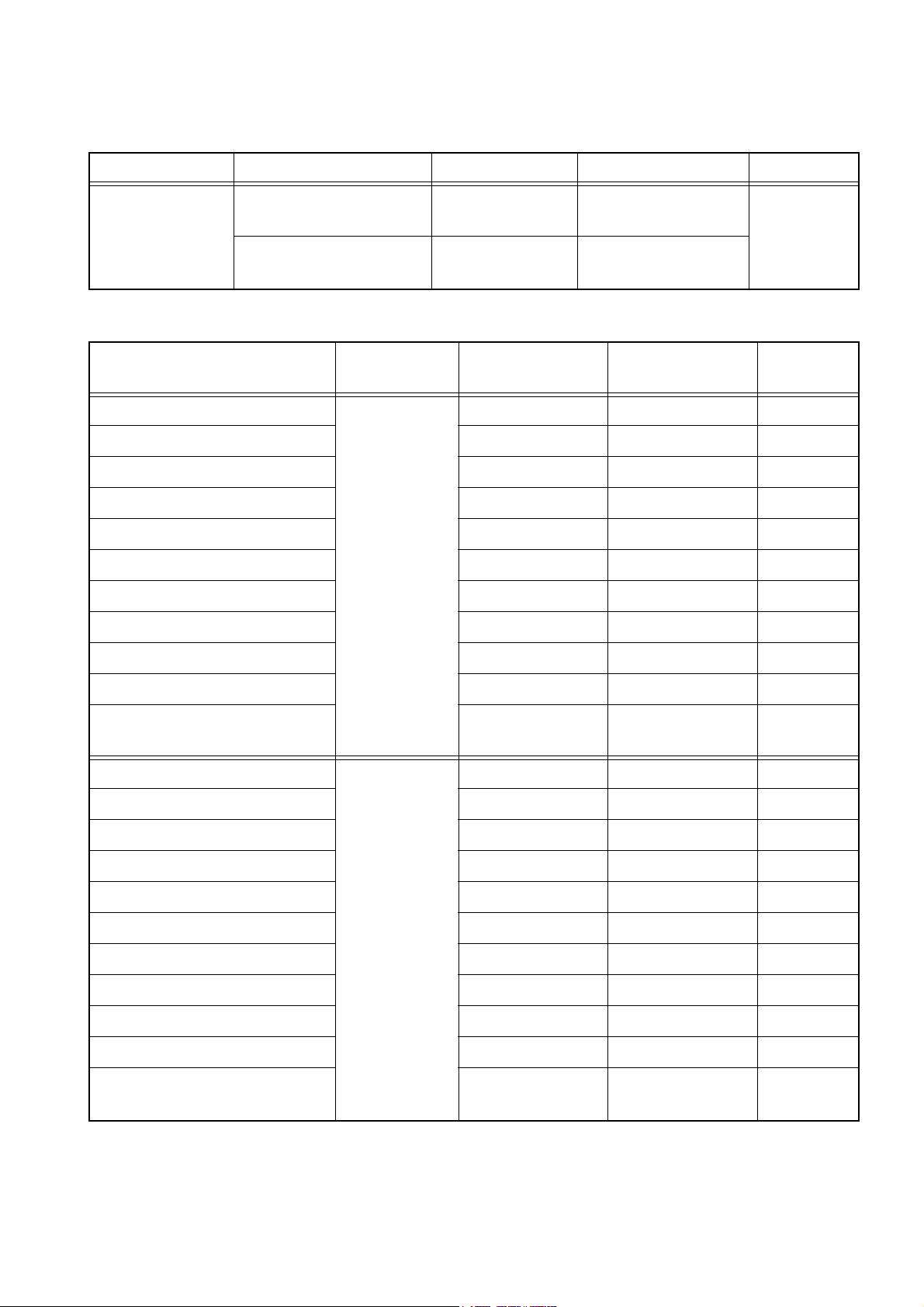
1.1 Application
Vehicle Name Vehicle Model Engine Model Exhaust Volume Reference
HINO145, HINO165,
HINO185
J05D 4.73L
Medium Truck
HINO238, HINO268,
HINO308, HINO338
J08E 7.68L
1.2 System Components Parts Number
Part Name
Supply Pump
Vehicle
Name
DENSO Part
Number
294050-0011 22730-1311A
Car Manufacturer
Part Number
Injector 095000-5281 23910-1360A
Rail 095440-0480 22760-1180A
Engine ECU 102758-3010 89560-6540A
Accelerator Position Sensor 198800-3160 78010-1200A
Coolant Temp. Sensor 071560-0110 83420-1250A
Crankshaft Position Sensor 029600-0570 89410-1280A
Cylinder Recognition Sensor 949979-1360 89410-1590A
Medium Truck
HINO238,
HINO268,
HINO308,
HINO338
Sales from
Early ’04
Reference
Intake Air Pressure Sensor 079800-5890 89390-1080A
EGR Valve 135000-7091 17350-1220A
Air Flow Meter 197400-2000 22204-21010B
Supply Pump
294000-0251 22730-1321A
Injector 095000-5391 23910-1310A
Rail 095440-0530 22760-1220A
Engine ECU 102758-3010 89560-6540A
Accelerator Position Sensor 198800-3160 78010-1200A
Coolant Temp. Sensor 071560-0110 83420-1250A
Crankshaft Position Sensor 029600-0570 89410-1280A
Medium Truck
HINO145,
HINO165,
HINO185
Cylinder Recognition Sensor 949979-1360 89410-1590A
Intake Air Pressure Sensor 079800-5890 89390-1080A
EGR Valve 135000-7071 17350-1210A
Air Flow Meter 197400-2000 22204-21010B
For EGR
Control
For EGR
Control
1
Page 4
2. Outline
2.1 Features of System
The common rail system was developed primarily to cope with exhaust gas regulations for
diesel engines, and aimed for 1. further improved fuel economy; 2. noise reduction; and 3.
high power output.
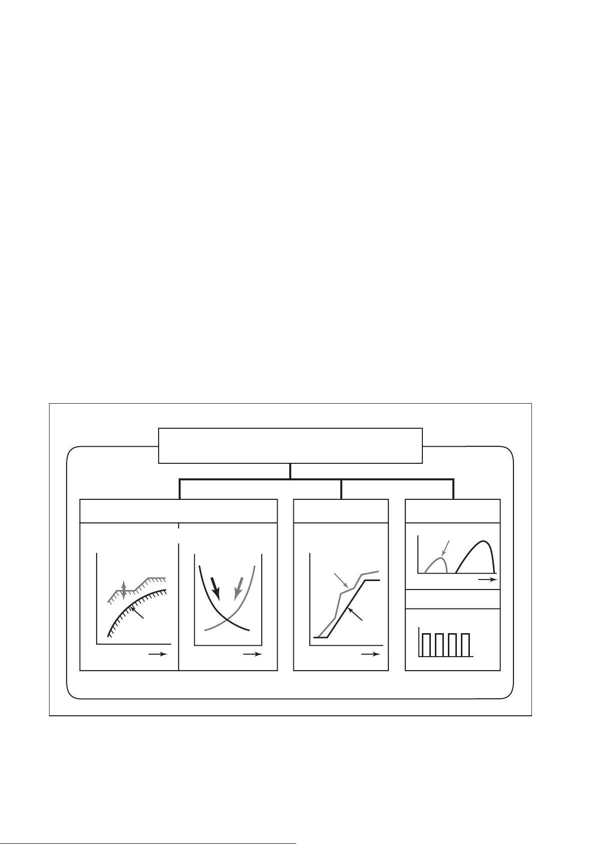
[1] System Characteristics
The common rail system uses a type of accumulation chamber called a rail to store pressurized fuel, and injectors that contain electronically controlled solenoid valves to spray the pressurized fuel into the cylinders. Because the engine ECU controls the injection system
(including the injection pressure, injection rate, and injection timing), the system is unaffected
by the engine speed or load. This ensures a stable injection pressure at all times, particularly
in the low engine speed range, and dramatically decreases the amount of black smoke ordinarily emitted by a diesel engine during start-up and acceleration. As a result, exhaust gas
emissions are cleaner and reduced, and higher power output is achieved.
(1) Injection Pressure Control
a. Enables high-pressure injection, even in the low engine speed range.
b. Optimizes control to minimize particulate matter and NOx emissions.
(2) Injection Timing Control
a. Optimally controls the timing to suit driving conditions.
(3) Injection Rate Control
a. Pilot injection control sprays a small amount of fuel before the main injection.
Common Rail System
Injection Pressure Control
Optimization, High Pressurization
Common Rail System
Conventional
Injection Pressure
Pump
Speed
Particulate
Injection
Pressure
Injection Timing Control
Optimization
Common Rail System
NOx
Injection Timing
Conventional
Pump
Speed
Injection Rate Control
Pilot Injection
Injection Rate
Crankshaft Angle
Injection Quantity Control
Cylinder Injection
Volume Correction
Speed
㧝㧟㧠㧞
Main
Injection
(4) EGR (Exhaust Gas Recirculation) Control
a. By recirculating the exhaust gas into the intake side of the engine, the combustion
temperature is reduced and NOx is decreased.
2
QD0734E
Page 5
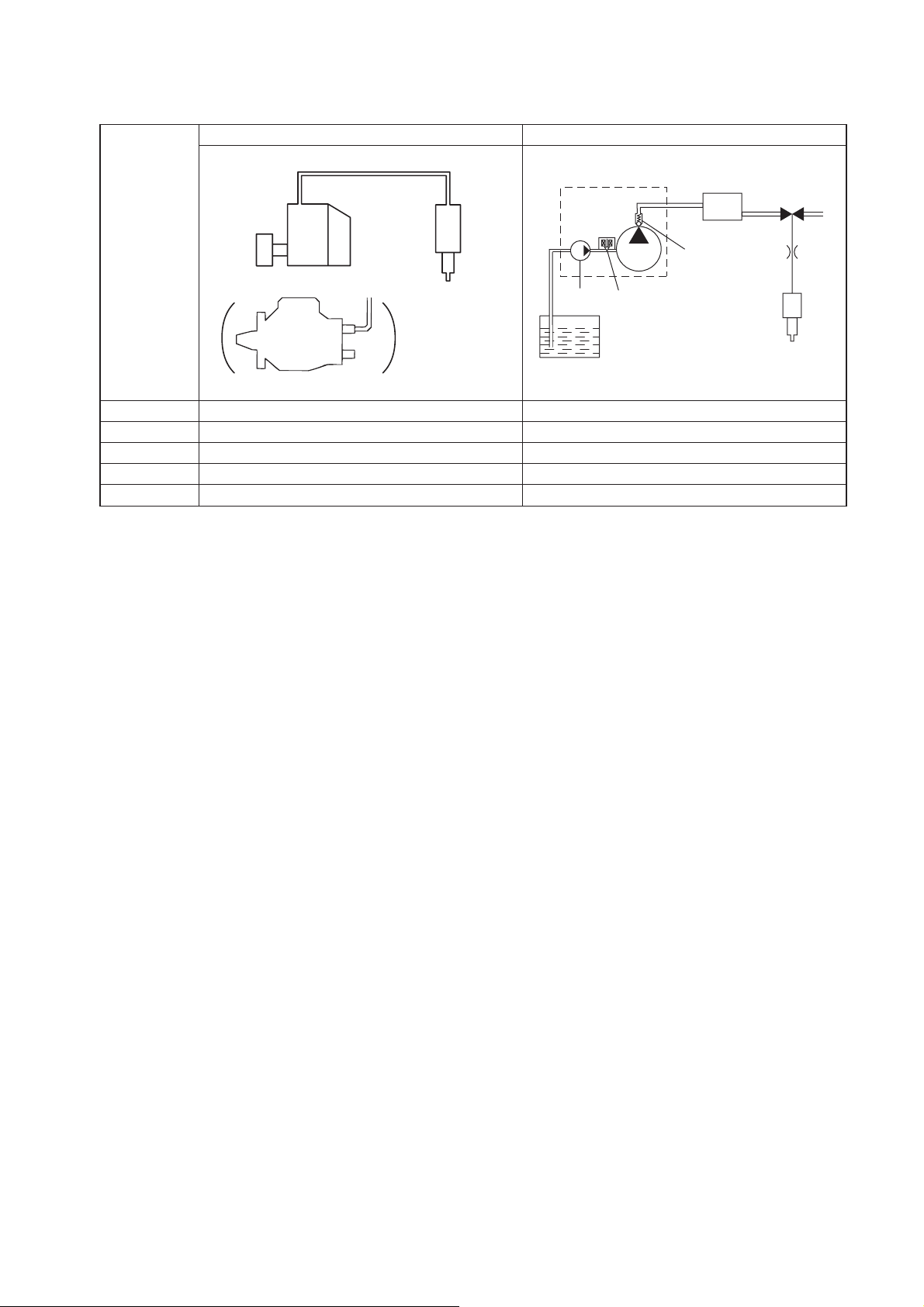
[2] Comparison to the Conventional System
In-line, VE Pump
High-pressure Pipe
Momentary High Pressure
Timer
System
In-line Pump
VE Pump
Injection Quantity Control
Injection Timing Control
Pump (Governor)
Pump (Timer)
Rising Pressure
Distributor Pump
Injection Pressure Control
Dependent upon Speed and Injection Quantity
Governor
Pump
Common Rail System
Rail
Nozzle
Supply Pump
Usually High Pressure
Delivery Valve
Feed Pump
SCV (Suction Control Valve)
Injector
Fuel Tank
Engine ECU, Injector (TWV)*
Engine ECU, Injector (TWV)*
1
1
Engine ECU, Supply Pump
Engine ECU, Rail
Engine ECU, Supply Pump (SCV)*
*1 TWV: Two Way Valve *2 SCV: Suction Control Valve
TWV
2
QD2341E
3
Page 6
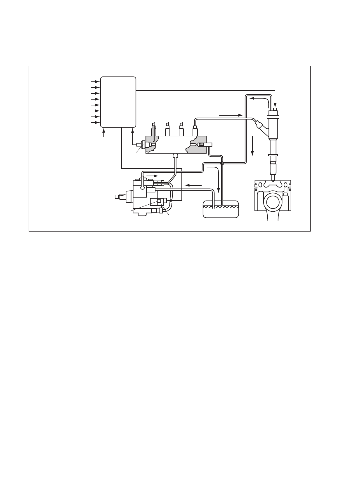
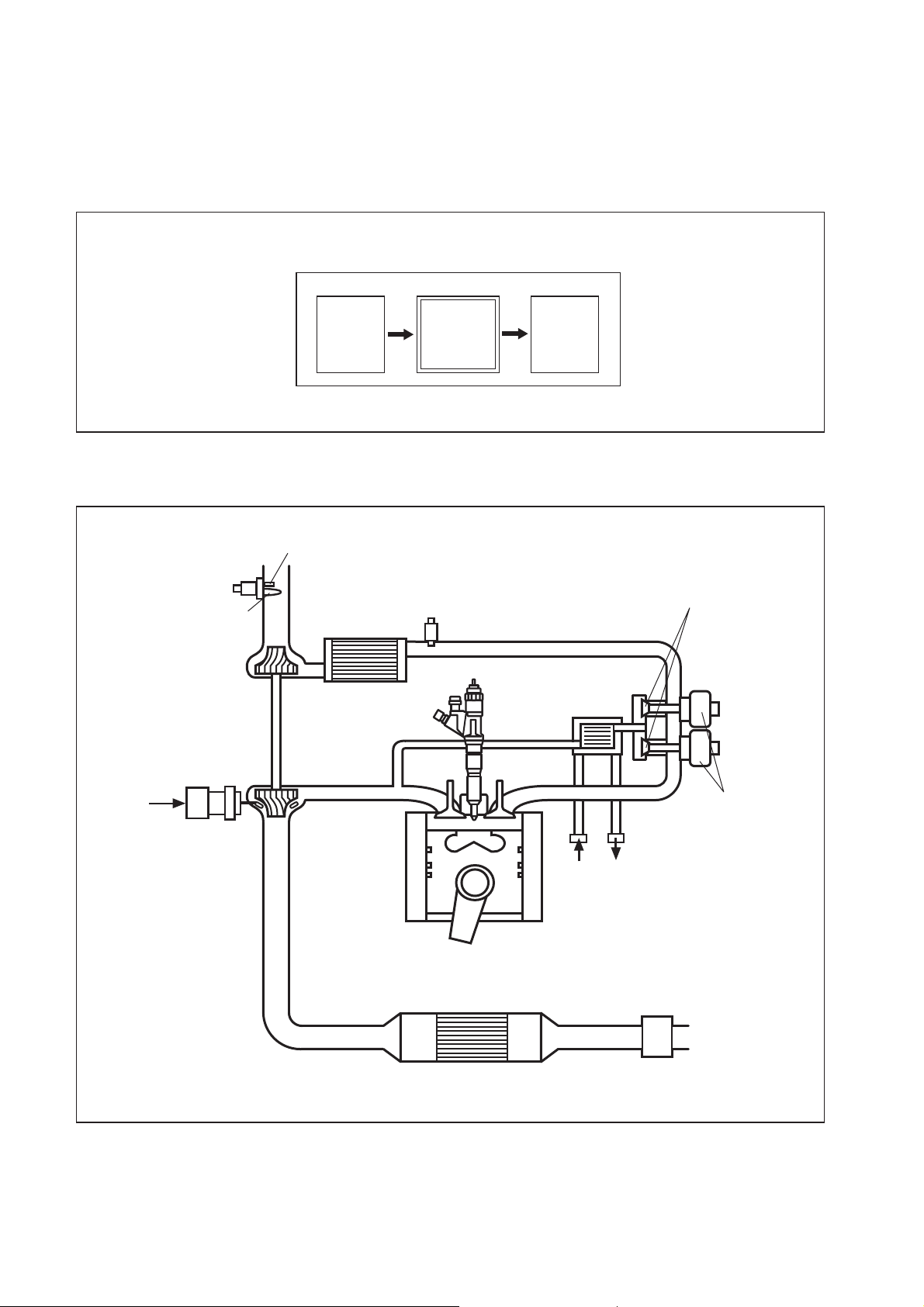
2.2 Outline of System [1] Composition
The common rail system consists primarily of a supply pump, rail, injectors, and engine ECU.
Fuel Temperature Sensor
Vehicle Speed
Accelerator Opening
Intake Air Pressure
Intake Air Temperature
Coolant Temperature
Crankshaft Position
Cylinder Recognition Sensor
Intake Airflow Rate
Engine ECU
Rail Pressure
Sensor
Rail
Pressure
Limiter
Injector
Fuel Temperature Sensor
Supply Pump
SCV (Suction
Control Valve)
Fuel Tank
[2] Operation
(1) Supply pump (HP3)
a. The supply pump draws fuel from the fuel tank, and pumps the high pressure fuel to the
rail. The quantity of fuel discharged from the supply pump controls the pressure in the
rail. The SCV (Suction Control Valve) in the supply pump effects this control in
accordance with the command received from the ECU.
(2) Rail
a. The rail is mounted between the supply pump and the injector, and stores the high-
pressure fuel.
(3) Injector (G2 type)
a. This injector replaces the conventional injection nozzle, and achieves optimal injection by
effecting control in accordance with signals from the ECU. Signals from the ECU
determine the length of time and the timing in which current is applied to the injector. This
in turn, determines the quantity, rate and timing of the fuel that is injected from the
injector.
Q000144E
(4) Engine ECU
a. The engine ECU calculates data received from the sensors to comprehensively control
the injection quantity, timing and pressure, as well as the EGR (exhaust gas
recirculation).
4
Page 7
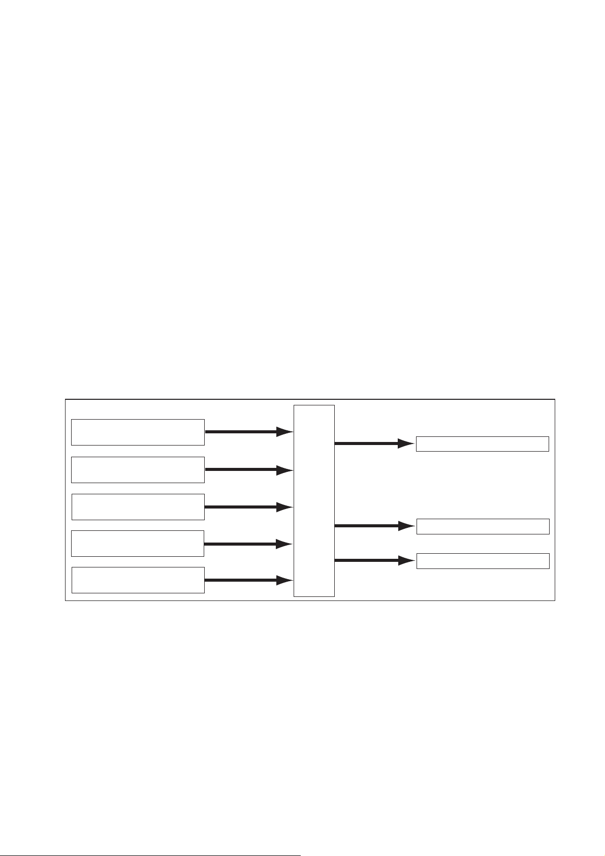
2.3 Fuel System and Control System [1] Fuel System
This system comprises the route through which diesel fuel flows from the fuel tank to the supply pump, via the rail, and is injected through the injector, as well as the route through which
the fuel returns to the tank via the overflow pipe.
[2] Control System
In this system, the engine ECU controls the fuel injection system in accordance with the signals received from various sensors. The components of this system can be broadly divided
into the following three types: (1) Sensors; (2) ECU; and (3) Actuators.
(1) Sensors
a. Detect the engine and driving conditions, and convert them into electrical signals.
(2) Engine ECU
a. Performs calculations based on the electrical signals received from the sensors, and
sends them to the actuators in order to achieve optimal conditions.
(3) Actuators
a. Operate in accordance with electrical signals received from the ECU. Injection system
control is undertaken by electronically controlling the actuators. The injection quantity
and timing are determined by controlling the length of time and the timing in which the
current is applied to the TWV (Two-Way Valve) in the injector. The injection pressure is
determined by controlling the SCV (Suction Control Valve) in the supply pump.
Sensor
Crankshaft Position Sensor NE
Cylider Recognition Sensor G
Accelerator Position Sensor
Rail Pressure Sensor
Other Sensors and Switches
Engine Speed
Cylinder Recognition
Load
Actuator
Injector
•Injection Quantity Control
•Injection Timing Control
Engine
ECU
Supply Pump (SCV)
•Injection Pressure Control
EGR, Engine Warning Light
Q000282E
5
Page 8
3. Construction and Operation
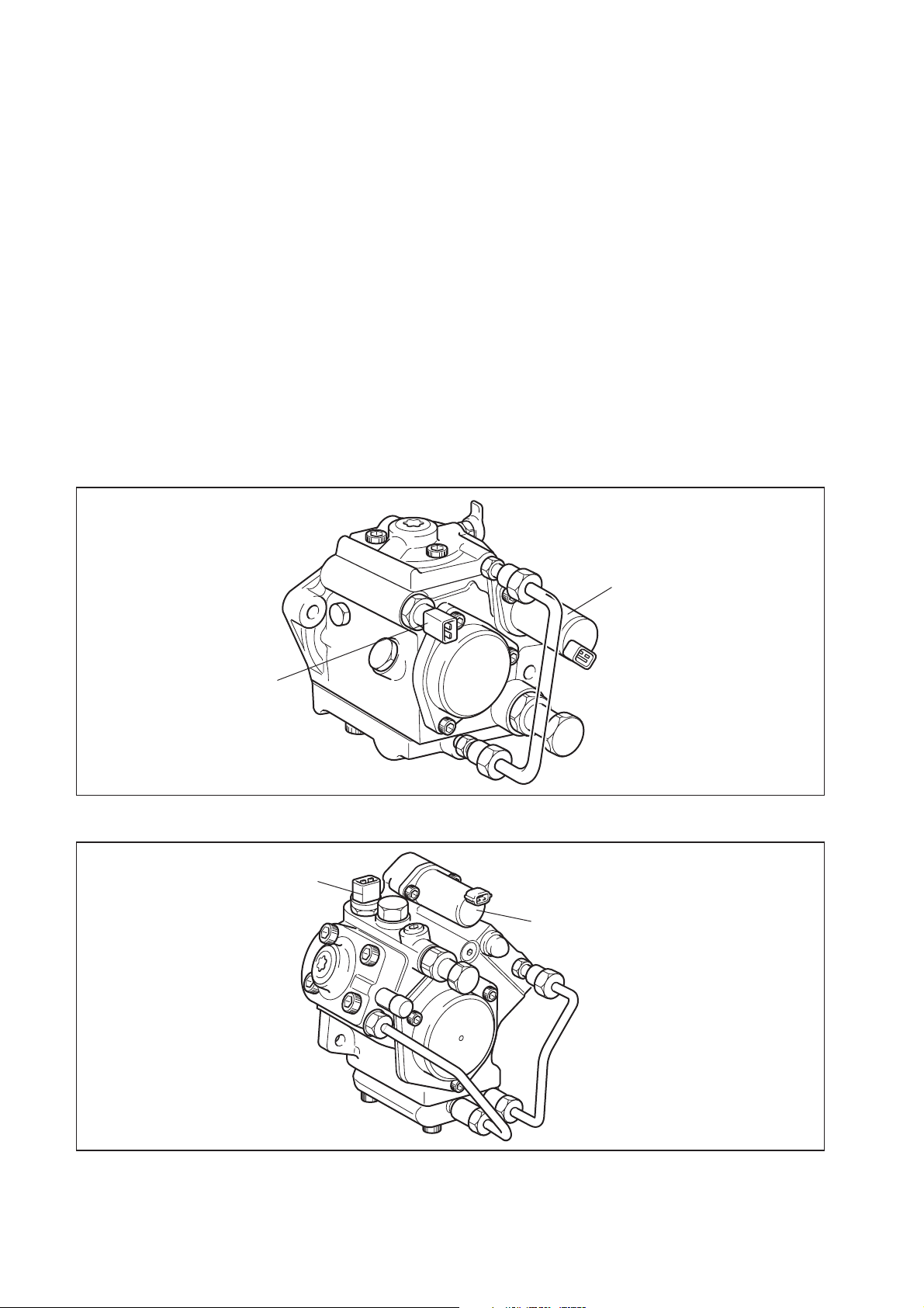
3.1 Description of Main Components [1] Supply Pump (HP3, HP4)
(1) Outline
a. The supply pump consists primarily of the pump body (cam shaft, ring cam, and
plungers), SCV (Suction Control Valve), fuel temperature sensor, and feed pump.
b. The two plungers for HP3 or the three plungers for HP4 are positioned vertically on the
outer ring cam for compactness.
c. The engine drives the supply pump at a ratio of 1:1. The supply pump has a built-in feed
pump (trochoid type), and draws the fuel from the fuel tank, sending it to the plunger
chamber.
d. The internal camshaft drives the two plungers, and they pressurize the fuel sent to the
plunger chamber and send it to the rail. The quantity of fuel supplied to the rail is
controlled by the SCV, using signals from the engine ECU. The SCV is a normally
opened type (the intake valve opens during de-energization).
HP3
Fuel Temperature Sensor
HP4
Fuel Temperature Sensor
SCV
Q000252E
SCV
Q000253E
6
Page 9
Injector
Rail
Discharge Valve
Intake Valve
Plunger
Intake Pressure
Feed Pressure
High Pressure
Return Pressure
Return Spring
Fuel Tank
Return
Fuel Overflow
Camshaft
Filter
SVC
Regulating Valve
Feed Pump
Fuel Inlet
Intake
Fuel Filter (with Priming Pump)
QD0704E
7
Page 10
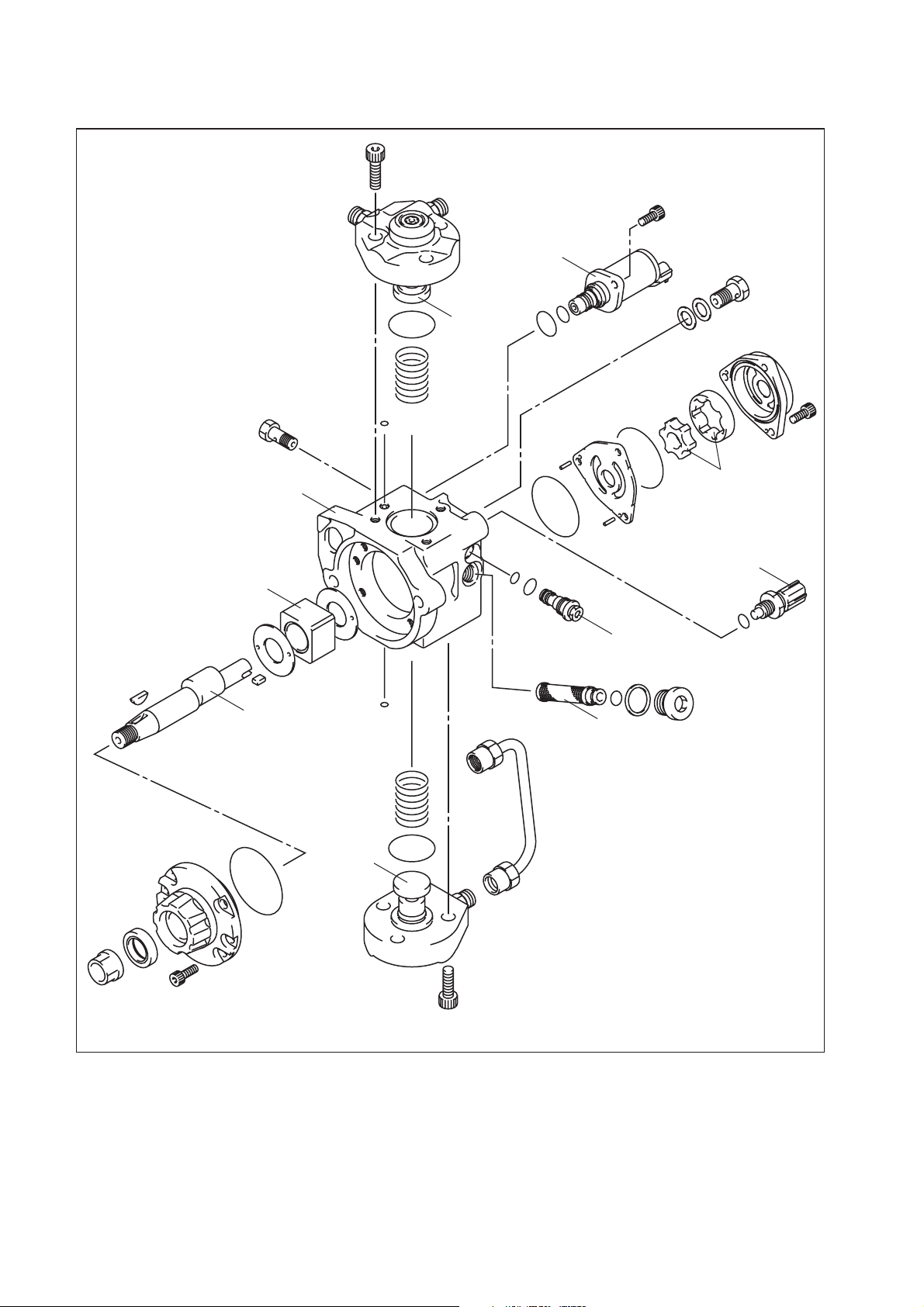
HP3
Pump Body
Ring Cam
SCV
Plunger
Feed Pump
Fuel Temperature
Sensor
Drive Shaft
Regulating
Valv e
Filter
Plunger
Q000254E
8
Page 11
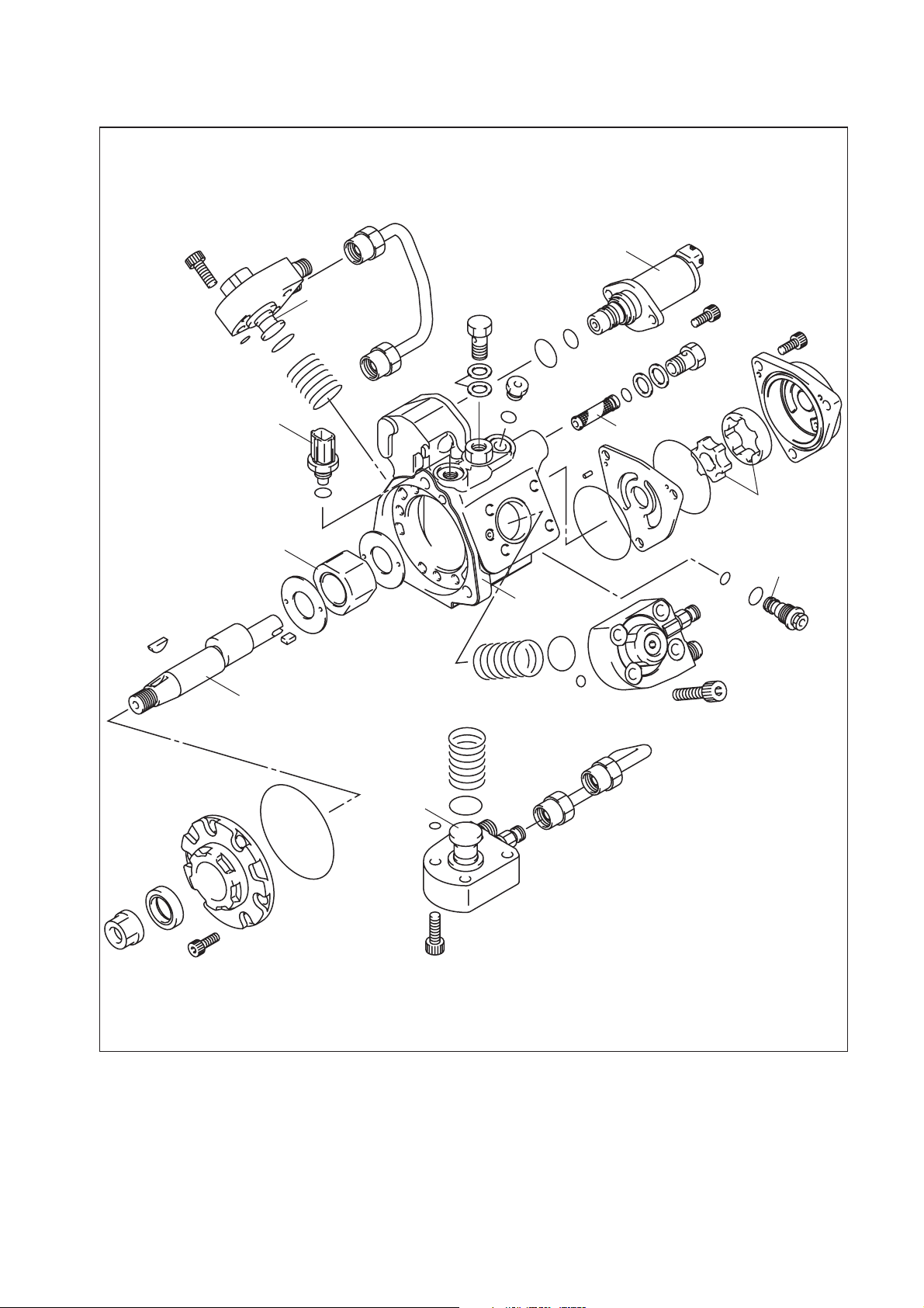
HP4
SCV
Plunger
Fuel Temperature
Sensor
Ring Cam
Drive Shaft
Filter
Feed Pump
Regulating
Valv e
Pump Body
Plunger
Q000255E
9
Page 12
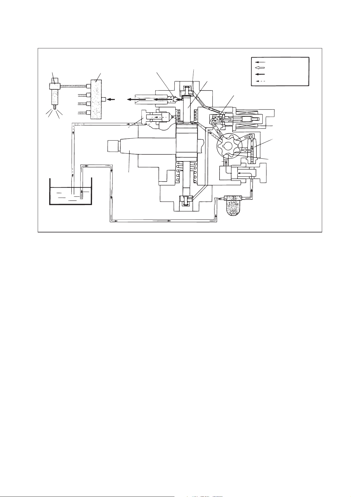
(2) Supply Pump Internal Fuel Flow
a. The fuel that is drawn from the fuel tank passes through the route in the supply pump as
illustrated, and is fed into the rail.
Supply Pump Interior
Regulating Valve
Feed Pump
Overflow
Fuel Tank
SCV (Suction Control Valve)
Intake Valve
Pumping Portion (Plunger)
Rail
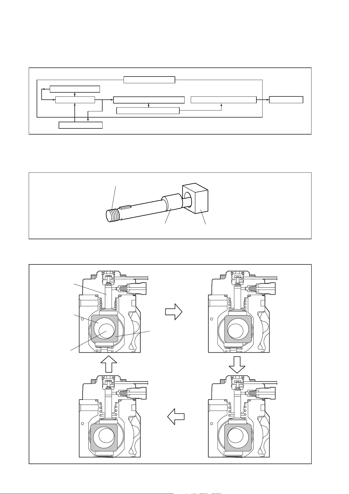
(3) Construction of Supply Pump (in case of HP3 pump)
a. The eccentric cam is attached to the cam shaft. The eccentric cam is connected to the
ring cam.
Cam Shaft
Eccentric Cam
Ring Cam
b. As the cam shaft rotates, the eccentric cam rotates eccentrically, and the ring cam moves
up and down while rotating.
Q000283E
QD0706E
Plunger
Eccentric Cam
Cam Shaft
Ring Cam
10
QD0727E
Page 13
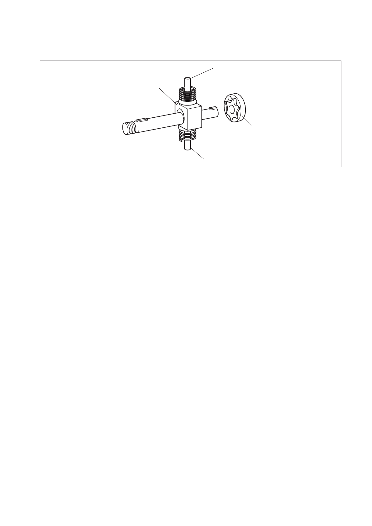
c. The plunger and the suction valve are attached to the ring cam. The feed pump is
connected to the rear of the cam shaft.
Plunger A
Ring Cam
Feed Pump
Plunger B
QD0728E
11
Page 14
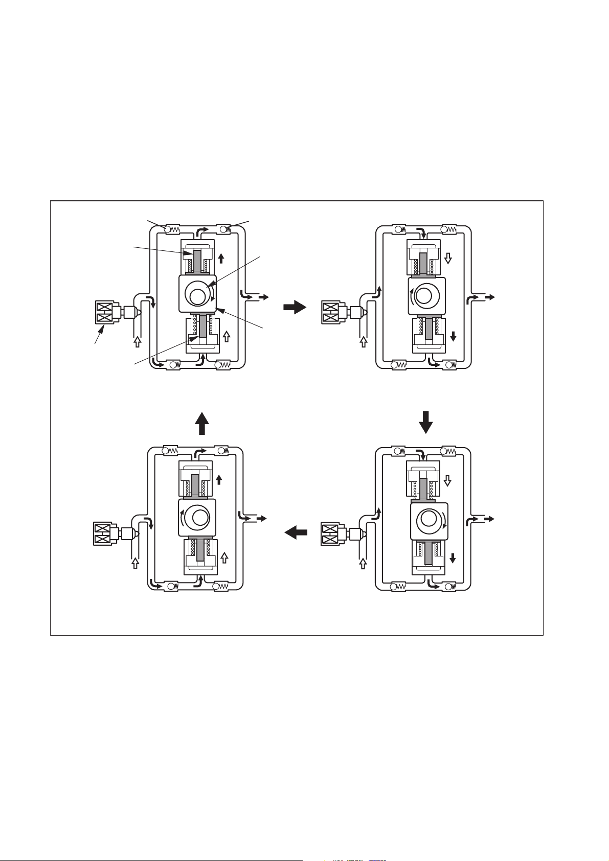
(4) Operation of the Supply Pump
a. As shown in the illustration below (in case of HP3 pump), the rotation of the eccentric cam
causes the ring cam to push Plunger A upwards. Due to the spring force, Plunger B is
pulled in the opposite direction to Plunger A. As a result, Plunger B draws in fuel, while
Plunger A pumps it to the rail. In the case of the 4-cylinder engine used with the HP3
pump, each plunger pumps fuel in a reciprocal movement during the 360° cam rotation.
Conversely, in the case of the 6-cylinder engine used with the HP4 pump, 3 plungers
pump fuel in a reciprocal movement for each one rotation of the cam.
Suction Valve
Plunger A
SCV
Plunger B
Delivery Valve
Eccentric Cam
Ring Cam
Plunger A: Complete Compression
Plunger B: Complete Intake
Plunger A: Begin Intake
Plunger B: Begin Compression
Plunger A: Begin Compression
Plunger B: Begin Intake
NOTE:
There are 3 plungers for the HP4.
Plunger A: Complete Intake
Plunger B: Complete Compression
QD0707E
12
Page 15
[2] Description of Supply Pump Components
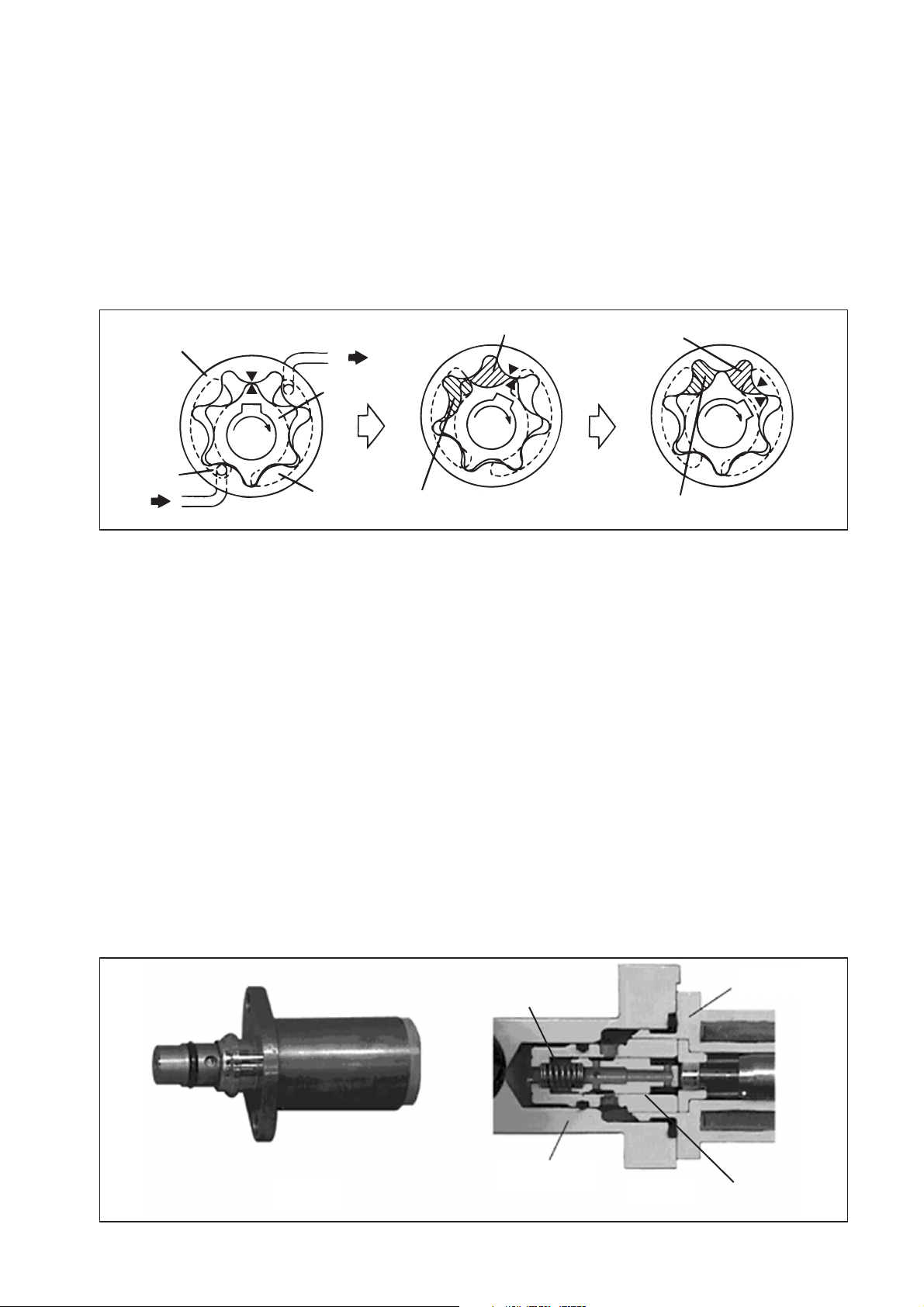
(1) Feed Pump
a. The trochoid type feed pump, which is integrated in the supply pump, draws fuel from the
fuel tank and feeds it to the two plungers via the fuel filter and the SCV (Suction Control
Valve). The feed pump is driven by the drive shaft. With the rotation of the inner rotor,
the feed pump draws fuel from its suction port and pumps it out through the discharge
port. This is done in accordance with the space that increases and decreases with the
movement of the outer and inner rotors.
Outer Rotor
Intake Port
from Fuel Tank
to Pump Chamber
Inner Rotor
Discharge
Port
Quantity Decrease
Quantity Increase
Quantity Decrease (Fuel Discharge)
Quantity Increase (Fuel Intake)
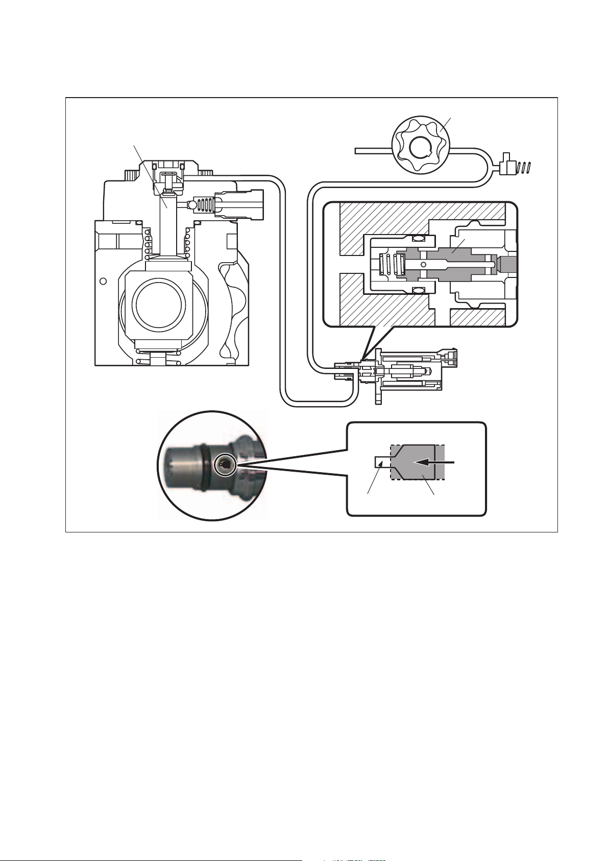
(2) SCV: Suction Control Valve (Normally open type)
a. A linear solenoid type valve has been adopted. The ECU controls the duty ratio (the
duration in which current is applied to the SCV), in order to control the quantity of fuel
that is supplied to the high-pressure plunger.
b. Because only the quantity of fuel that is required for achieving the target rail pressure is
drawn in, the actuating load of the supply pump decreases.
c. When current flows to the SCV, variable electromotive force is created in accordance with
the duty ratio, moving the armature to the left side. The armature moves the cylinder to
the left side, changing the opening of the fuel passage and thus regulating the fuel
quantity.
d. With the SCV OFF, the return spring contracts, completely opening the fuel passage and
supplying fuel to the plungers. (Full quantity intake and full quantity discharge)
e. When the SCV is ON, the force of the return spring moves the cylinder to the right, closing
the fuel passage (normally opened).
f. By turning the SCV ON/OFF, fuel is supplied in an amount corresponding to the actuation
duty ratio, and fuel is discharged by the plungers.
QD0708E
Exterior View of SCV
Cross-section of SCV
Return Spring
Pump Body
13
SCV
Cylinder
Q000270E
Page 16

[In case of short time ON duty]
Short time ON duty → large valve opening → maximum intake quantity
Plunger
SCV
Feed Pump
Cylinder
Large Opening
Cylinder
Q000051E
14
Page 17
[In case of long time ON duty]
Long time ON duty → small valve opening → minimum intake quantity
Plunger
SCV
Feed Pump
Cylinder
Small Opening
Cylinder
Q000052E
15
Page 18

[3] Rail
(1) Outline
a. Stores pressurized fuel (0 to 150 MPa {0 to 1528.5 kg/cm2}) that has been delivered from
the supply pump and distributes the fuel to each cylinder injector. A rail pressure sensor
and a pressure limiter are adopted in the rail.
b. The rail pressure sensor (Pc sensor) detects the fuel pressure in the rail and sends a
signal to the engine ECU, the pressure limiter prevents the rail pressure from being
abnormally high. This ensures optimum combustion and reduces combustion noise.
Pressure Limiter
Pressure Sensor
(2) Pressure Limiter
a. The pressure limiter opens to release the pressure if an abnormally high pressure is
generated.
b. When the rail pressure reaches approximately 200 MPa (2038 kg/cm2), it trips the
pressure limiter (the valve opens). When the pressure drops to approximately 50 MPa
(509.5 kg/cm2), the pressure limiter returns to its normal state (the valve closes) in order
to maintain the proper pressure.
Valve Open
Valve Close
50 MPa (509.5 kg/cm
200 MPa (2038 kg/cm
2
)
Q000256E
2
)
Q000257E
Q000271E
16
Page 19

(3) Pressure Sensor
a. The rail pressure sensor (Pc sensor) is attached to the rail in order to detect the fuel
pressure.
b. It is a semiconductor type pressure sensor that utilizes the characteristics of silicon,
whereby the electrical resistance changes when pressure is applied to it.
4.2 V
VC VOUT GND
Q000258E
1.0 V
0 200 MPa (2038 kg/cm
Q000272E
REFERENCE:
It is necessary to reset the ECU default value using the Hino diagnosis tool at the time of
supply pump service replacement. In addition, the ECU has a function enabling it to learn
the performance of the supply pump at the time of ECU service replacement, so ensure
sufficient time (several minutes) is available.
2
)
17
Page 20

[4] Injector (G2 Type)
(1) Outline
a. The injectors inject the high-pressure fuel from the rail into the combustion chambers at
the optimum injection timing, rate, and spray condition, in accordance with commands
received from the ECU.
(2) Characteristics
a. A compact, energy-saving solenoid-control type TWV (Two-Way Valve) injector has been
adopted.
b. QR codes displaying various injector characteristics and the ID codes showing these in
numeric form (30 alphanumeric figures) are engraved on the injector head. The J05/J08
engine common rail system optimizes injection volume control using this information.
When an injector is newly installed in a vehicle, it is necessary to enter the ID codes in
the engine ECU using the HINO Diagnostic tool.
(3) Construction
30 Alphanumeric Figures
Control Chamber
Pressurized Fuel
(from Rail)
Command Piston
A
A
BCD
A
BCD
A
BCD
BCD
EF
EFGH
EFGH
E
FGH
QR Codes
Solenoid Valve
Nozzle Spring
Pressure Pin
Nozzle Needle
Q000259E
18
Page 21
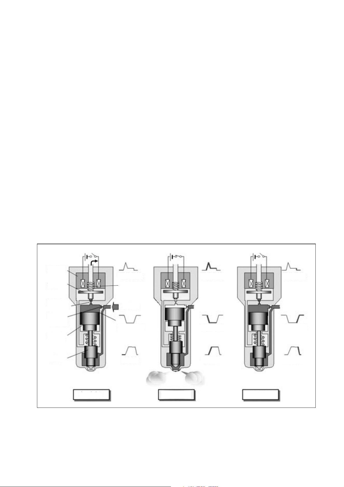
(4) Operation
a. The TWV (Two-Way Valve) solenoid valve opens and closes the outlet orifice to control
both the pressure in the control chamber, and the start and end of injection.
[No injection]
• When no current is supplied to the solenoid, the spring force is stronger than the hydraulic
pressure in the control chamber. Thus, the solenoid valve is pushed downward, effectively
closing the outlet orifice. For this reason, the hydraulic pressure that is applied to the
command piston causes the nozzle spring to compress. This closes the nozzle needle, and
as a result, fuel is not injected.
[Injection]
• When current is initially applied to the solenoid, the attraction force of the solenoid pulls the
solenoid valve up, effectively opening the outlet orifice and allowing fuel to flow out of the
control chamber. After the fuel flows out, the pressure in the control chamber decreases,
pulling the command piston up. This causes the nozzle needle to rise and the injection to
start.
• The fuel that flows past the outlet orifice flows to the leak pipe and below the command
piston. The fuel that flows below the piston lifts the piston needle upward, which helps
improve the nozzle's opening and closing response.
• When current continues to be applied to the solenoid, the nozzle reaches its maximum lift,
where the injection rate is also at the maximum level. When current to the solenoid is turned
OFF, the solenoid valve falls, causing the nozzle needle to close immediately and the
injection to stop.
Solenoid
TWV
Outlet orifice
Inlet orifice
Command
piston
Nozzle
needle
Leak pipe
No injection
Actuation
current
Valve spring
Rail
Control chamber
pressure
Injection rate
Injection
Actuation
current
Control chamber
pressure
Injection rate
Actuation
current
Control chamber
pressure
Injection rate
End of injection
Q000149E
19
Page 22

(5) QR Codes
a. In order to minimize performance tolerance of injectors at replacing them, QR*1 (Quick
Response) codes have been adopted to enhance correction precision.
b. Using QR codes has resulted in a substantial increase in the number of fuel injection
quantity correction points, and thus the injection quantity control precision has improved.
The characteristics of the engine cylinders have been further unified, contributing to
improvements in combustion efficiency, reductions in exhaust gas emissions and so on.
[QR code correction points]
Injection quantity Q
*1: Location of QR codes
QR code on the injector connector
Pressure Parameter
Actuating pulse width TQ
QR Codes ( 9.9mm)
ID Codes
(30 alphanumeric figures)
16 figure alphanumeric notations of
fuel injection quantity correction
information for market service use.
Q000260E
20
Q000261E
Page 23

(6) Repair Procedure Changes
a. Differences in comparison with the conventional method of replacing injectors assembly
are as shown below.
NOTE:
When replacing injectors with QR codes, or the engine ECU, it is necessary to record the
ID codes (QR codes) in the ECU. (If the ID codes of the installed injector are not registered
correctly, engine failure such as rough idling and noise will result.)
New (Injector with QR Codes)
30 alphanumeric figures-sixteen figure alphanumeric notations of fuel injection
quantity correction information displaed for market service use
ID Code
Replacing the Injector
Q000284E
"No correction resistance, so no electrical recognition capability"
Spare Injector
Replacing the Engine ECU
"No correction resistance, so no electrical recognition capability"
Vehicle-side Injector
Engine ECU
* Necessary to record the injector ID codes in Engine ECU
QD1536E
Spare Engine ECU
* Necessary to record the injector ID codes in the engine ECU
QD1537E
21
Page 24
[5] Engine ECU (Electronic Control Unit)
(1) Outline
a. This is the command center that controls the fuel injection system and engine operation
in general.
Outline Diagram
Sensor
Detection
Engine ECU
Calculation
3.2 Description of Control System Components [1] Engine Control System Diagram
Intake Air Temperature Sensor
Mass Airflow Meter
Inter-Cooler
Intake Air Pressure Sensor
Actuator
Actuation
QD2352E
EGR Valve
(J08E-double, J05D-single)
G2 Injector
EGR Cooler
VGT
Controller
EGR Valve Lift
Sensor
VGT Actuator
Coolant
Oxidation Catalyst
Q000262E
22
Page 25
[2] Sensor and Relays
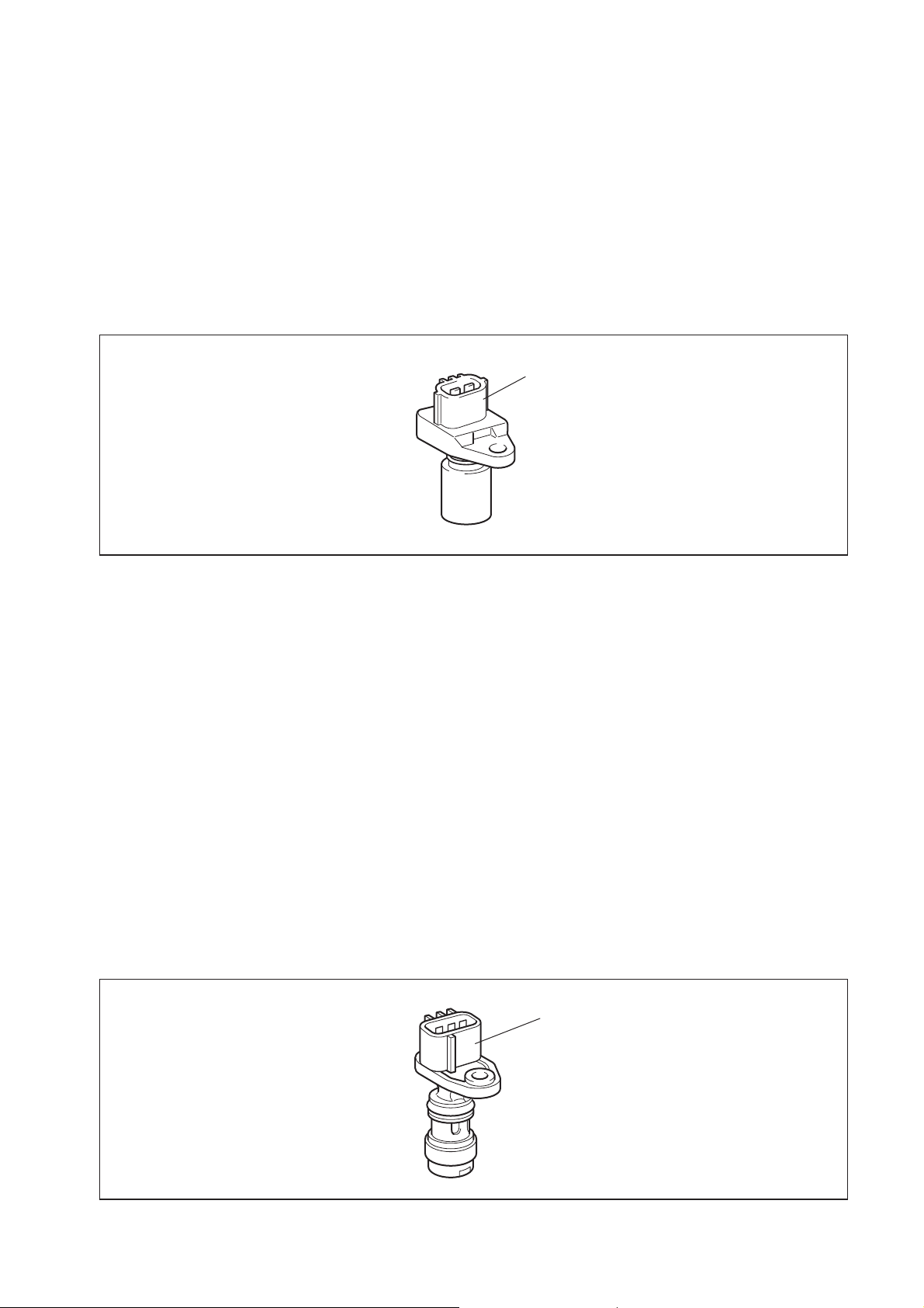
(1) NE Sensor (Crankshaft Position Sensor)
a. When the signal holes on the flywheel move past the sensor, the magnetic line of force
passing through the coil changes, generating alternating voltage.
b. The signal holes are located on the flywheel at 6.5-degree intervals. There are a total of
56 holes, with holes missing in three places. Therefore, every two revolutions of the
engine outputs 112 pulses.
c. This signal is used to detect the engine speed and the crankshaft position in 7.5-degree
intervals.
NE (Crankshaft Position) Sensor
Q000263E
(2) TDC Sensor (Cylinder Recognition Sensor)
a. Unlike the NE sensor, the TDC sensor is an MRE (magnetic resistance element) sensor.
As the pulsar near the sensor revolves, the magnetic field changes. This causes
variations in the generated current, which are amplified in the internal circuits of the
sensor unit before a signal is output to the engine ECU.
b. The engine camshaft gear (one revolution for every two revolutions of the engine) is used
as a pulsar. The J05D and J08E use different types of gear, so the signal outputs differ
as follows.
For the J05D:
In addition to four knock pins located at 90-degree intervals, there is an extra signal hole on
the gear. Therefore every revolution of the gear, i.e. two revolutions of the engine, outputs
4 + 1 = 5 TDC signal pulses.
For the J08E:
In addition to six knock pins located at 60-degree intervals, there is an extra signal hole on
the gear. Therefore every revolution of the gear, i.e. two revolutions of the engine, outputs
6 + 1 = 7 TDC signal pulses.
TDC (Cylinder Recognition) Sensor
23
Q000264E
Page 26

c. A combination of the NE pulse and the TDC pulses are used for the cylinder reference
pulse, and the irregular pulse is used to determine the No. 1 cylinder.
For the J08E engine
The cylinder at a rotation of 78° following the No. 1 TDC reference signal after the irregular
pulse is the number one cylinder TDC (refer to the chart on the following page).
For J08E
VCC
TDC
GND
NE
GND
ECU
VCC
Input circuit
Input circuit
Q000273E
For the J05D engine
The cylinder at a rotation of 96° following the No. 1 TDC reference signal after the irregular
pulse is the number one cylinder TDC (refer to the chart on the following page).
For J05D
VCC
TDC
ECU
VCC
Input circuit
GND
NE
GND
Input circuit
Q000274E
24
Page 27
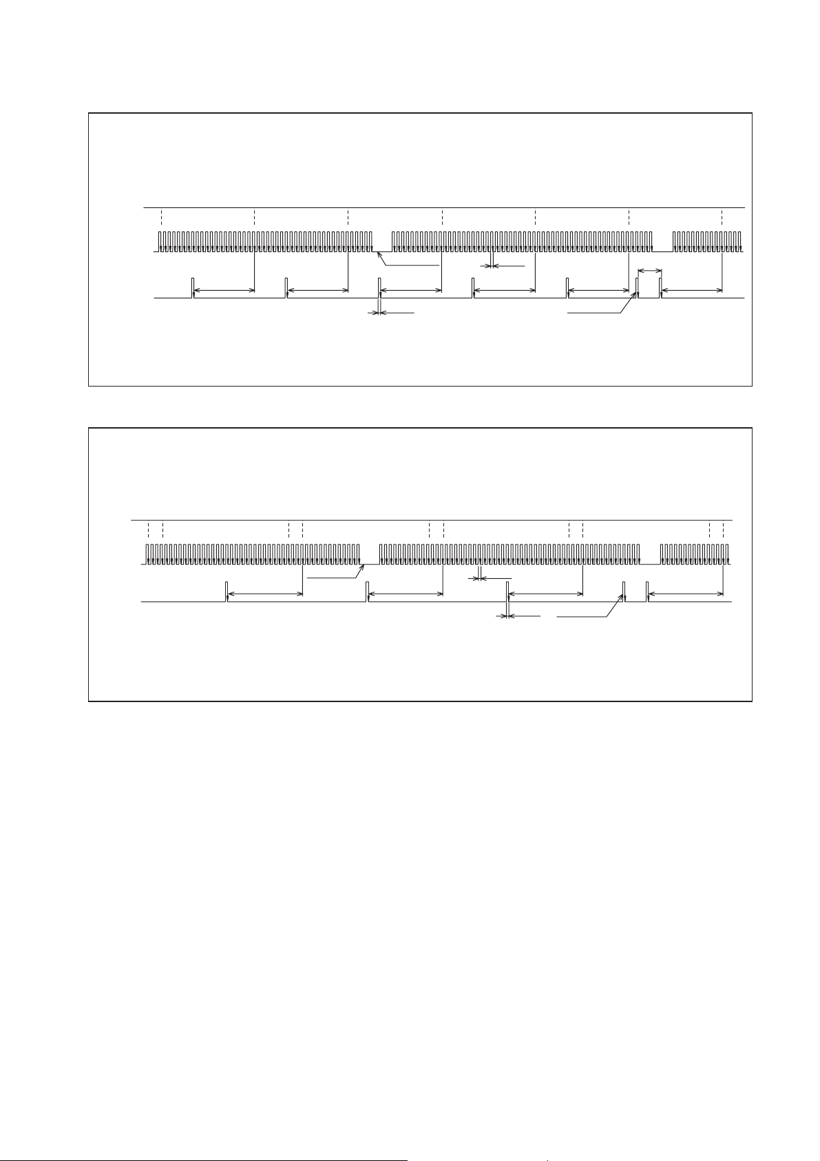
For J08E
0°CA 120°CA 240°CA 360°CA 480°CA 600°CA 720°CA
NE+
11 12 13 14 15 16 17 18 19 20 21 22 23 24 25 26 27 28 29 30 31 32 33 34 35 36 37 38 39 40 41 42 43 44 45 46 47 48 49 50 51 52 53 54 55 56 1 2 3 4 5 6 7 8 9 10 11 12 13 14 15 16 17 18 19 20 21 22 23 24 25 26 27 28 29 30 31 32 33 34 35 36 37 38 39 40 41 42 43 44 45 46 47 48 49 50 51 52 53 54 55 56
(NE- Standard)
G
(G-GND Standard)
For J05D
0°CA 180°CA 360°CA 540°CA 0°CA
#1TDC
NE+
(NE- Standard)
G
(G- Standard)
11 12 13 14 15 16 17 18 19 20 21 22 23 24 25 26 27 28 29 30 31 32 33 34 35 36 37 38 39 40 41 42 43 44 45 46 47 48 49 50 51 52 53 54 55 56 1 2 3 4 5 6 7 8 9 10 11 12 13 14 15 16 17 18 19 20 21 22 23 24 25 26 27 28 29 30 31 32 33 34 35 36 37 38 39 40 41 42 43 44 45 46 47 48 49 50 51 52 53 54 55 56
#5TDC
#3TDC
4th Missing Tooth
#6TDC
3°CA
#2TDC
#4TDC
30°CA
78°CA 78°CA 78°CA 78°CA 78°CA 78°CA
#3TDC
4th Missing Tooth
3°CA
#4TDC
3°CA
Extra Tooth
#2TDC
1 2 3 4 5 6 7 8 9 10 11 12 13 14 15
96°CA 96°CA 96°CA 96°CA
Extra Tooth
3°CA
1 2 3 4 5 6 7 8 9 10 11 12 13 14 15
#1TDC
Q000275E
#1TDC
Q000276E
25
Page 28
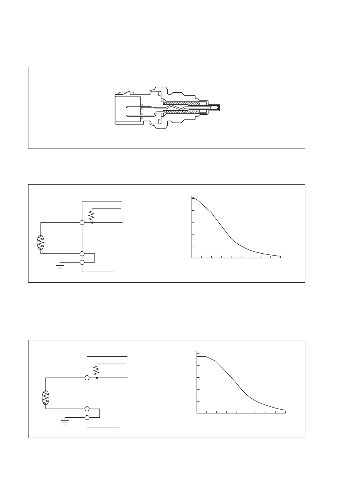
(3) Coolant Temperature Sensor
a. The coolant temperature sensor detects the temperature of the engine coolant and
outputs it to the ECU.
b. The sensor uses a thermistor, which varies resistance according to temperature. As the
ECU applies voltage to the thermistor, it uses a voltage resulting from the division of the
computer internal resistance and the thermistor resistance to detect the temperature.
(V)
ECU
+5V
VTHW
Output Voltage
VTHW
5
4
3
2
Q000277E
A-GND
1
0
-40 -20
-40 -4
0 20
40 60
32
68 104 140 176 212 248 (°F)
80 100 120 (°C)
Coolant Temperature
(4) Fuel Temperature Sensor (THL)
a. The fuel temperature sensor detects the fuel temperature and outputs it to the ECU. The
sensor uses a thermistor, which varies resistance according to temperature. As the ECU
applies voltage to the thermistor, it uses a voltage resulting from the division of the
computer internal resistance and the thermistor resistance to detect the temperature.
VTHL
ECU
+5V
VTHL
Output Voltage
A-GND
(V)
5
4
3
2
1
0
-40 -20
-40 -4
0 20
40 60
32
68 104 140 176 212 248 (°F)
Fuel Temperature
80 100 120 (°C)
THW
Q000105E
THL
Q000106E
26
Page 29

(5) Atmospheric Air Pressure Sensor (Built-in ECU)
a. This sensor converts the atmospheric air pressure into an electrical signal to correct full-
load injection volume.
VPATM
Output Voltage (V)
3.8
107 {1.09}
Atmospheric Air Pressure (kPa {kg/cm2})
(6) Accelerator Position Sensor
a. This sensor converts the angle of the pedal effort applied to the accelerator pedal into
electrical signals and sends them to the ECU. The accelerator sensor uses hall
elements. A magnet is mounted on the shaft that moves in unison with the accelerator
pedal, and the magnetic field orientation changes with the rotation of the shaft. The
changes in the magnetic field orientation generate voltage.
VPA1 GND1 VC1 VPA 2 GND2 VC2
Q000278E
Hall elements
(2 pieces)
Magnets
(1 pair)
VPA1
GND1
VC1
V
PA2
GND2
VC2
V
PA1
GND1
VC1
V
PA2
GND2
VC2
Output Voltage
5
4
3
2
1.6 V
0.8 V
1
0 5 10 15 20
Q000266E
VPA2
4.0 V
PA1
V
3.2 V
Accelerator Opening Angle (°)
Q000265E
27
Page 30

(7) Boost Pressure Sensor
a. In order to correct the full-load injection volume, this sensor converts the intake air
pressure (absolute pressure) into an electrical signal, then amplifies it into a voltage
signal to the computer.
A-VCC
VPIM
A-GND
ECU
+5V
Output Valtage (V)
VPIM
4.0
3.45
2.0
0.5
0
100 200 300
{1.019}
{2.038} {3.057}
Intake Air Pressure PIM (kPa {kg/cm2})
(8) Air Flow Sensor
a. Detects the intake airflow (mass flow rate) in the hot-wire type airflow meter.
b. The intake airflow is converted to a voltage value and this signal is transmitted to the ECU.
E2 THA VG E2G +B
Q000279E
Airflow Sensor
Intake Air Temperature
Sensor
Q000280E
c. The airflow sensor is installed to the rear of the air cleaner, and consists of a heater,
thermometer, intake air temperature sensor, and control circuit (base). It diverts a portion
of the intake air from the air cleaner and measures the intake airflow at the hot-wire
measuring part.
Outline Diagram of Hot-Wire Type Airflow Meter
Throttle Body
Temperature Compensating Resistor
(Hot-Wire)
Heating Resistor
(Hot-Wire)
Intake Air from
Air Cleaner
Intake Air Temperature Sensor
Bypass Flow
28
Q000285E
Page 31

3.3 Various Types of Control
This system controls the fuel injection quantity and injection timing more optimally than the
mechanical governor or timer used in conventional injection pumps.
For system control, the ECU makes the necessary calculations based on signals received
from sensors located in the engine and on the vehicle in order to control the timing and duration in which current is applied to the injectors, thus realizing optimal injection timing.
(1) Fuel Injection Rate Control Function
a. The fuel injection rate control function controls the ratio of the quantity of fuel that is
injected through the nozzle hole during a specified period.
(2) Fuel Injection Quantity Control Function
a. The fuel injection quantity control function, replaces the conventional governor function,
and controls fuel injection to achieve an optimal injection quantity based on the engine
speed and the accelerator opening.
(3) Fuel Injection Timing Control Function
a. The fuel injection timing control function, replaces the conventional timer function, and
controls the fuel injection to achieve an optimal injection timing according to the engine
speed and the injection quantity.
(4) Fuel Injection Pressure Control Function (Rail Pressure Control Function)
a. The fuel injection pressure control function (rail pressure control function) uses a rail
pressure sensor to measure fuel pressure, and feeds this data to the ECU to control the
pump discharge quantity.
b. Pressure feedback control is implemented to match the optimal quantity (command
quantity) set according to the engine speed and the fuel injection quantity.
Input Signal
Accelerator sensor
NE Sensor
(Crankshaft Position Sensor)
TDC Sensor
(Cylinder Recognition Sensor)
Rail Pressure Sensor
Various Sensors
·Water Temperature Sensor
·Fuel Temperature Sensor
·Atmospheric Air Temperature
Sensor etc.
Fuel Control Computer
(ECU)
Atmospheric Air
Pressure Sensor
Control Output
Fuel Injection Rate Control
Fuel Injection Quantity Control
Fuel Injection Timing Control
Fuel Injection Pressure Control
Diagnosis
29
Q000109E
Page 32
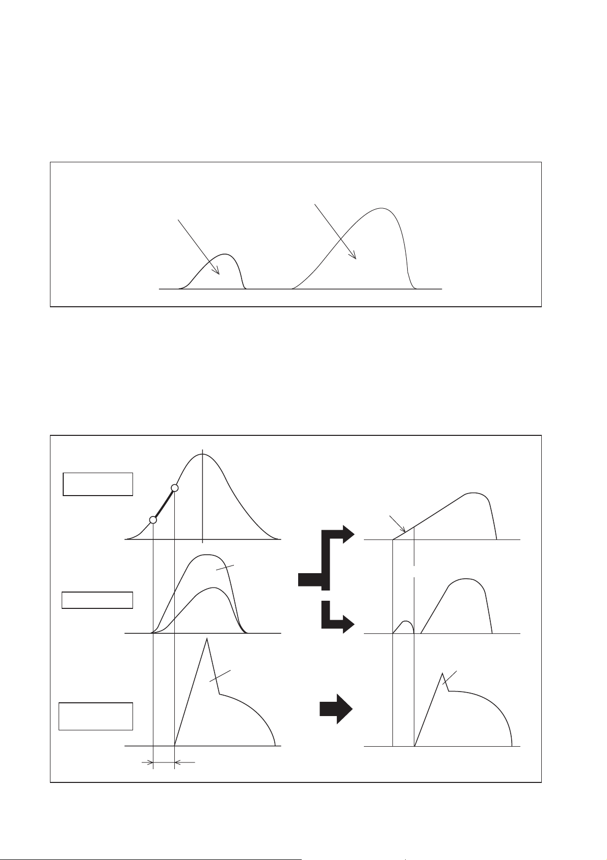
[1] Fuel Injection Rate Control
(1) Main Injection
a. Same as conventional fuel injection.
(2) Pilot Injection
a. Pilot injection is the injection of a small amount of fuel prior to the main injection.
Main Injection
Pilot Injection
b. While the adoption of higher pressure fuel injection is associated with an increase in the
injection rate, the lag (injection lag) that occurs from the time fuel is injected until
combustion starts cannot be reduced below a certain value. As a result, the quantity of
fuel injected before ignition increases, resulting in explosive combustion together with
ignition, and an increase in the amount of NOx and noise. Therefore, by providing a pilot
injection, the initial injection rate is kept to the minimum required level dampening, the
explosive first-period combustion and reducing NOx emissions.
Q000110E
Combustion
Process
Injection Rate
Heat Generation
Rate
TDC
High Injection
Rate
Large Pre-mixture
Combustion
(NOx, Noise)
Small Injection Amount
Prior to Ignition
Pilot Injection
Improvement
Small Pre-mixture
Combustion
Ignition Delay
Q000111E
30
Page 33

(3) Split Injection
a. When the rotation is low at starting time, a small amount of fuel is injected several times
prior to main injection.
Split Injection
[2] Fuel Injection Quantity Control
(1) Starting Injection Quantity
a. The injection quantity is determined based on the engine speed (NE) and water
temperature while starting.
Starting Injection Quantity
Q000112E
Water
Temperature
Engine Speed
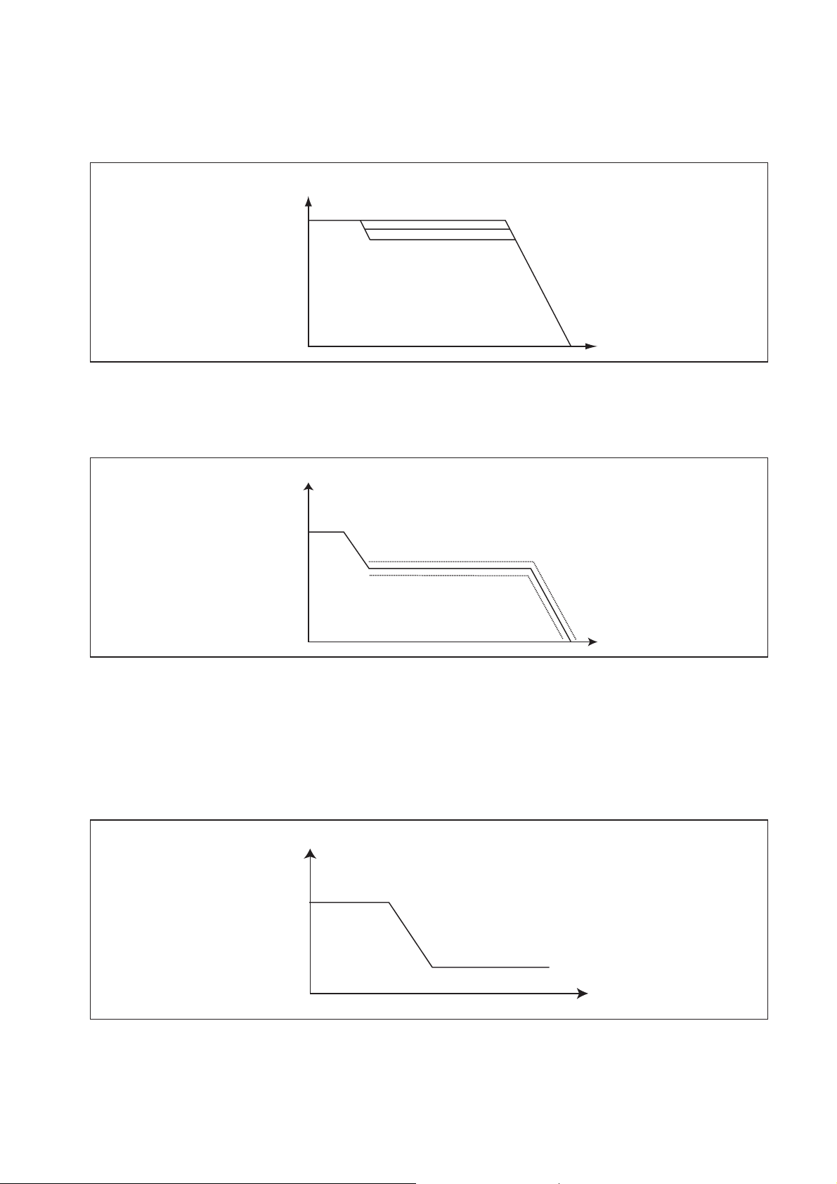
(2) Transient Injection Quantity Correction
a. When the changes in the accelerator opening are great during acceleration, the increase
in fuel volume is delayed to inhibit the discharge of black smoke.
Injection Quantity
Change in Accelerator Opening
Injection Quantity after Correction
Delay Time
Time
Q000127E
Q000128E
31
Page 34

(3) Basic Injection Quantity
a. This quantity is determined in accordance with the engine speed (NE) and the accelerator
opening.
b. Increasing the accelerator opening while the engine speed remains constant causes the
injection quantity to increase.
Basic Injection Quantity
Accelerator Opening
Engine Speed
(4) Injection Quantity for Maximum Speed Setting
a. The injection quantity is regulated by a value that is determined in accordance with the
engine speed.
Injection Quantity for Maximum Speed Setting
Engine Speed
(5) Maximum Injection Quantity
a. Is determined in accordance with the engine speed and corrected by the coolant
temperature signal.
Q000129E
Q000130E
Basic Maximum Injection Quantity
32
Engine Speed
Q000131E
Page 35
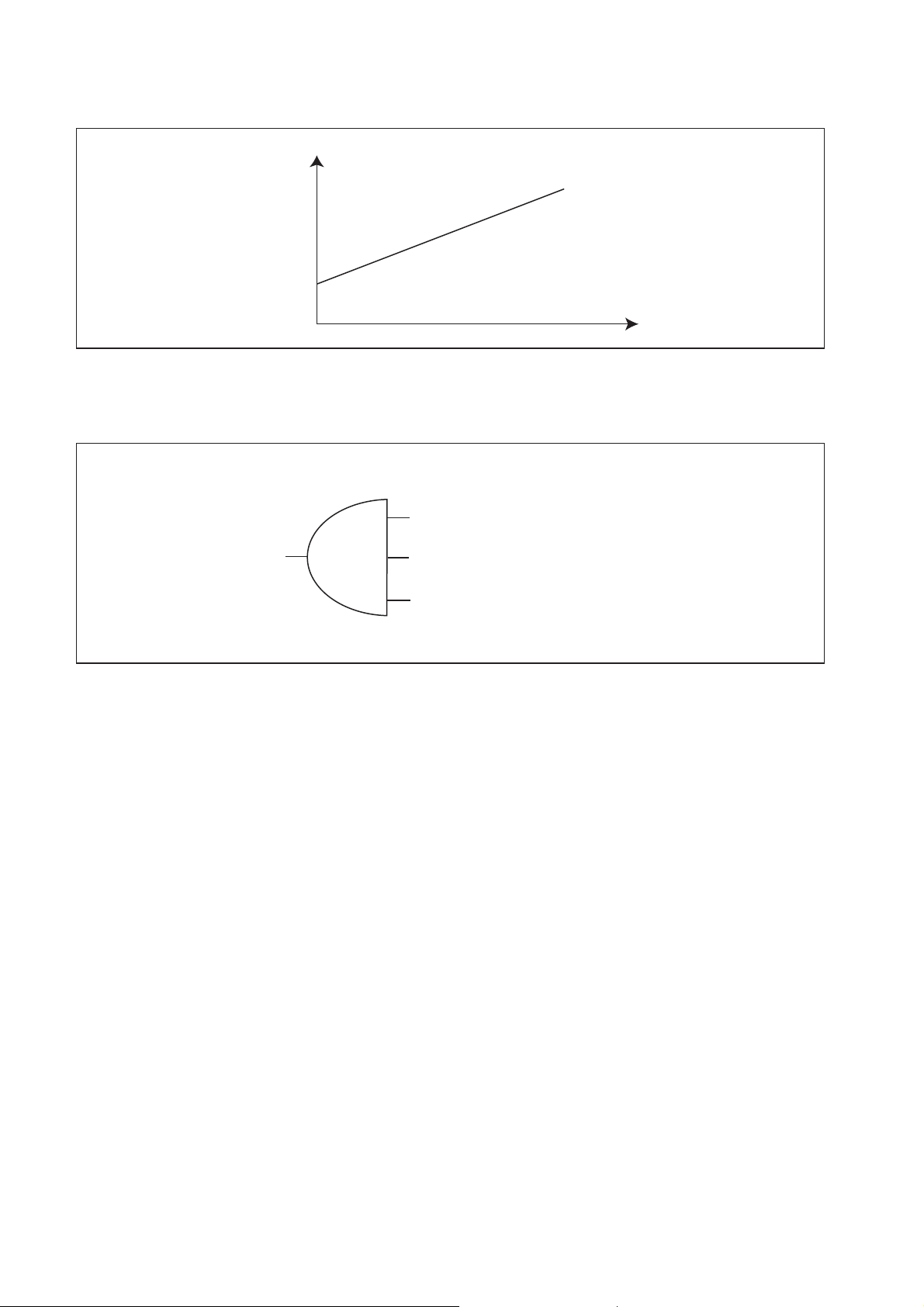
(6) Amount of Injection Quantity Intake Pressure Correction
a. Limits the maximum injection quantity in accordance with the intake pressure, in order to
minimize the discharge of smoke when the intake air pressure is low.
Amount of Intake Air Pressure Correction
Engine Speed
(7) Amount of Injection Quantity by Atmospheric Air Pressure Correction
a. With using atmospheric air pressure sensor signal, the maximum injection quantity curve
is corrected as shown in the right figure.
Amount of Atmospheric Air Pressure Correction
Engine Speed
(8) Idle Speed Control System (ISC)
a. Controls the idle speed by regulating the injection quantity in order to match the target
speed, which has been calculated by the computer, with the actual speed. The functions
of the ISC can be broadly divided into the following two items:
• Auto ISC
Controls the idle speed in accordance with the water temperature.
Q000133E
Q000134E
Target Speed
Water Temperature
Q000135E
• Manual ISC
Controls the idle speed in accordance with the idle speed indicated on the manual idle setting
33
Page 36
knob provided at the driver's seat.
Target Speed
ISC Knob Terminal Voltage
Q000136E
• Air Conditioner Idle-up Control
When the conditions shown in the chart on the right are realized, bring the idle-up speed to
constant rpm.
Conditions
Air Conditioning SW = "ON"
Clutch SW = "ON" (Clutch Connection)
Neutral SW = "ON" (Neutral)
(9) Auto Cruise Control
a. Controls the actual vehicle speed by regulating the injection quantity in order to match
the target speed that has been calculated by the computer with the actual speed.
b. The CRS ECU controls the injection quantity in accordance with signals from the cruise
control computer.
Q000137E
34
Page 37

[3] Fuel Injection Timing Control
The characteristics of the fuel injection timing vary depending on whether it is the main injection or the pilot injection. Although either the NE sensor or the auxiliary NE sensor is the reference for controlling the injection timing, the NE sensor is ordinarily used for this purpose.
(1) Main Injection Timing
a. The basic injection timing is calculated in accordance with the final injection quantity, the
engine speed, and the water temperature (with map correction).
b. While starting, it is calculated in accordance with the water temperature and the engine speed.
Basic Injection Timing
Final Injection Quantity
Engine Speed
Q000138E
(2) Pilot Injection timing (Pilot Interval)
a. The pilot injection timing is controlled by adding the pilot interval to the main injection timing.
b. The pilot interval is calculated in accordance with the final injection quantity, the engine
speed, and the water temperature (with map correction).
c. While starting, it is calculated in accordance with the water temperature and the engine speed.
Pilot Interval
Final Injection Quantity
Engine Speed
(3) Fuel Injection Pressure
a. A value is calculated as determined in accordance with the final injection quantity and the
engine speed.
b. While starting, it is calculated in accordance with the water temperature and the engine speed.
Q000139E
Rail Pressure
Final Injection Quantity
Engine Speed
Q000140E
35
Page 38

3.4 Other Relevant Engine Control [1] EGR Control
(1) Control System
EGR Target Opening
EGR Deviation Compensation
Control
ECU
Final EGR Target
Opening Calculation
Processing/Duty Ratio
Calculation
Feed Back
EGR Valve Lift Sensor
(Detects Actual Opening)
EGR Valve Assy
EGR Valve Actuation
Q000267E
(2) Related Sensors
The related sensors are as follows:
• Air volume sensor: Detects the volume of air flowing into the engine.
• Coolant temperature sensor: Detects the engine coolant temperature.
• Atmospheric pressure sensor: Detects the atmospheric pressure around the engine (built
into the ECU).
(3) EGR Valve
a. An EGR valve is utilized as the system actuator for the electric exhaust gas recirculation
(E-EGR) system. It is constructed of an upper section and a lower section. The upper
section receives output signals from the engine ECU, and contains a solenoid that
generates electromagnetic force. The lower section is constructed of a nozzle that
moves up and down in response to the electromagnetic force, and a valve with an
opening that alters in response to the nozzle position.
For J05D
Q000268E
For J08E
Q000281E
36
Page 39

(4) Control Operation
Operation Start Conditions: During engine warm-up, other than start-up, when not overheating (etc.).
EGR Operating Range: During medium engine load.
Q
NE
3.5 Engine ECU [1] Diagnosis Codes
P-Code DST-1 Display Remarks Description
P0045 VNT Malfunction For the VNT. The VNT actuator has a malfunction.
Q000269E
P0049
P0088
P0093
P0102
P0103
P0108
P0112
Turbo Charger Turbine
Over speed
Common Rail
Pressure -Too high
Fuel System Leak
Detected
Mass Air Flow Sensor
Malfunction (LO)
Mass Air Flow Sensor
Malfunction (HI)
Boost Pressure Sensor
Malfunction (HI)
Intake Air Temperature
Sensor Malfunction (LO)
The turbine rotation
sensor has been
detected.
The pump does not
work properly. (Fuel
leak)
Integrated in the mass
air flow sensor.
Over speed of the turbo has been detected.
High fuel pressure has been detected.
There is a possibility of the fuel leakage.
Perform the fuel leakage check.
"The mass air flow sensor has a malfunction.
There are possibilities of the sensor malfunction,
open and short circuit to ground in the harness."
The mass air flow sensor has a malfunction.
There are possibilities of the sensor malfunction and
short circuit to +B in the harness.
The boost pressure cannot be detected properly.
There are possibilities of the sensor malfunction and
short circuit in the harness.
"The temperature cannot be detected properly.
There are possibilities of the sensor malfunction,
short circuit to ground in the harness."
P0113
P0117
P0118
Intake Air Temperature
Sensor Malfunction (HI)
Engine Coolant
Temperature Sensor
Malfunction (LO)
Engine Coolant
Temperature Sensor
Malfunction (HI)
Integrated in the mass
air flow sensor.
37
"The temperature cannot be detected properly.
There are possibilities of the sensor malfunction,
open and short circuit to +B in the harness."
The temperature cannot be detected properly.
There are possibilities of the sensor malfunction and
short circuit to ground in the harness.
"The temperature cannot be detected properly.
There are possibilities of the sensor malfunction,
open and short circuit to +B in the harness."
Page 40

P-Code DST-1 Display Remarks Description
P0182
P0183
P0191
P0192
P0193
P0200
P0201 Injector 1 Open Circuit
P0202 Injector 2 Open Circuit
Fuel Temperature
Sensor Malfunction (LO)
Fuel Temperature
Sensor Malfunction (HI)
Rail Pressure Sensor
Malfunction
Rail Pressure Sensor
Malfunction (LO)
Rail Pressure Sensor
Malfunction (HI)
ECU Charge Circuit
Malfunction (HI)
Integrated in the supply
pump.
Integrated in the supply
pump.
Characteristic malfunction
"The temperature cannot be detected properly.
There are possibilities of the sensor malfunction,
short circuit to ground in the harness."
"The temperature cannot be detected properly.
There are possibilities of the sensor malfunction,
open and short circuit to +B in the harness."
The rail pressure cannot be detected properly.
There is a possibility of the sensor malfunction.
The rail pressure cannot be detected properly.
There are possibilities of the sensor malfunction and
short circuit to ground in the harness.
"The rail pressure cannot be detected properly.
There are possibilities of the sensor malfunction,
open and short circuit to +B in the harness."
The voltage for the injector activation is too high.
Replace the ECU.
There is a possibility of the Injector 1 malfunction or
open circuit in the harness.
There is a possibility of the Injector 2 malfunction or
open circuit in the harness.
P0203 Injector 3 Open Circuit
P0204 Injector 4 Open Circuit
P0205 Injector 5 Open Circuit
P0206 Injector 6 Open Circuit
P0217
P0219
P0234
P0237
P0263
Over Temperature
Condition
Engine Over speed
Condition
Turbo Charger
Overboost Condition
Boost Pressure Sensor
Malfunction (LO)
Correction Error
Between Cylinders #1
There is a possibility of the Injector 3 malfunction or
open circuit in the harness.
There is a possibility of the Injector 4 malfunction or
open circuit in the harness.
There is a possibility of the Injector 5 malfunction or
open circuit in the harness.
There is a possibility of the Injector 6 malfunction or
open circuit in the harness.
The over temperature condition has been detected.
Check the cooling system.
The engine speed exceeded the rated value.
The boost pressure is too higher than the specified
value.
"The intake air pressure cannot be detected properly.
There are possibilities of the sensor malfunction,
open and short circuit in the harness."
The rotation fluctuation in the cylinder 1 became bigger than other cylinders.
There is a possibility that the flow damper is operating.
P0266
Correction Error
Between Cylinders #2
The rotation fluctuation in the cylinder 2 became bigger than other cylinders.
There is a possibility that the flow damper is operating.
38
Page 41

P-Code DST-1 Display Remarks Description
The rotation fluctuation in the cylinder 3 became big-
P0269
P0272
P0275
P0278
Correction Error
Between Cylinders #3
Correction Error
Between Cylinders #4
Correction Error
Between Cylinders #5
Correction Error
Between Cylinders #6
ger than other cylinders.
There is a possibility that the flow damper is operating.
The rotation fluctuation in the cylinder 4 became bigger than other cylinders.
There is a possibility that the flow damper is operating.
The rotation fluctuation in the cylinder 5 became bigger than other cylinders.
There is a possibility that the flow damper is operating.
The rotation fluctuation in the cylinder 6 became bigger than other cylinders.
There is a possibility that the flow damper is operating.
P0335
P0340
P0404 EGR Valve 1 Clogged
P0405
P0406
P0407
P0408
Crankshaft Position
Sensor Malfunction
Engine Speed Sensor
Malfunction
EGR Lift Sensor 1
Malfunction (LO)
EGR Lift Sensor 1
Malfunction (HI)
EGR Lift Sensor 2
Malfunction (LO)
EGR Lift Sensor 2
Malfunction (HI)
"In case that the NE
and G sensor have
malfunctions, this P
code will be output."
Clogging has been
detected by the lift sensor.
The pulse from the crankshaft position sensor cannot be detected.
There are possibilities of the sensor and harness
malfunctions.
The pulse from the engine speed sensor cannot be
detected.
There are possibilities of the sensor and harness
malfunctions.
The EGR valve 1 is clogged in the open state.
"The EGR lift sensor 1 has a malfunction.
There are possibilities of the sensor malfunction,
open and short circuit to ground in the harness."
The EGR lift sensor 1 has a malfunction.
There are possibilities of the sensor malfunction and
short circuit to +B in the harness.
"The EGR lift sensor 2 has a malfunction.
There are possibilities of the sensor malfunction,
open and short circuit to ground in the harness."
The EGR lift sensor 2 has a malfunction.
There are possibilities of the sensor malfunction and
short circuit to +B in the harness.
P0489
P0490
P0500
EGR Solenoid Valve 1
Malfunction
EGR Solenoid Valve 1
Malfunction
Vehicle Speed Sensor
Malfunction (LO)
Open circuit
"The EGR solenoid valve 1 has a malfunction.
There are possibilities of the solenoid valve malfunction, open and short circuit to ground in the harness."
The EGR solenoid valve 1 has a malfunction.
There are possibilities of the solenoid valve malfunction and short circuit to +B in the harness.
The pulse from the vehicle speed sensor cannot be
detected .
There are possibilities of the sensor and harness
malfunctions.
39
Page 42

P-Code DST-1 Display Remarks Description
The pulse from the vehicle speed sensor has an
P0501
Vehicle Speed Sensor
Malfunction (HI)
Noise
error.
There are possibilities of the sensor and harness
malfunctions.
P0510 Idle Switch Malfunction
P0524
P1401 EGR Valve Clogged
P0540
P0545
P0546
P0605 Flash ROM Malfunction
P0606
Engine Oil Pressure Too
Low
Preheating System
Malfunction
Exhaust Gas Temperature Sensor 1
Malfunction (LO)
Exhaust Gas Temperature Sensor 1
Malfunction (HI)
CPU Malfunction (Hardware Detected)
Clogging has been
detected by the lift
sensor.
The idle switch does not function properly.
Monitor the state and check the ON/OFF judgment.
The engine oil pressure became too low.
The EGR valve 2 system is clogged in the open
state.
The intake heater relay has a malfunction.
There are possibilities of the relay and harness malfunctions.
The temperature cannot be detected properly.
There are possibilities of the sensor malfunction and
short circuit to ground in the harness.
"The temperature cannot be detected properly.
There are possibilities of the sensor malfunction,
open and short circuit to +B in the harness."
There is an internal malfunction in the ECU.
Replace the ECU.
There is an internal malfunction in the ECU.
Replace the ECU.
P0607
P0611
P0617
P0686 Main Relay Malfunction
P0704
P0850
P1132
P1133
CPU Monitoring ID
Malfunction
ECU Charge Circuit
Malfunction
Starter Switch
Malfunction
Clutch Switch
Malfunction
Neutral Switch
Malfunction
Accelerator Position
Sensor for Operation
(LO)
Accelerator Position
Sensor for Operation
(HI)
There is an internal malfunction in the ECU.
Replace the ECU.
The voltage for the injector activation is too low.
Replace the ECU.
There is a short in the starter switch circuit.
Monitor the state and check the ON/OFF judgment.
The main relay cannot be turned OFF.
Check the relay.
The clutch switch cannot be detected properly.
Monitor the state and check the ON/OFF judgment.
The neutral switch cannot be detected properly.
Monitor the state and check the ON/OFF judgment.
The accelerator position sensor for operation cannot
be detected properly.
Check the sensor voltage.
There are possibilities of open and short circuit to
ground.
The accelerator position sensor for operation cannot
be detected properly.
Check the sensor voltage.
There is a possibility of short circuit to +B.
40
Page 43

P-Code DST-1 Display Remarks Description
The idle volume cannot be detected properly. Check
P1142 Idle Volume (LO)
P1143 Idle Volume (HI)
the sensor voltage.
There are possibilities of open and short circuit to
ground.
The idle volume cannot be detected properly. Check
the sensor voltage.
There is a possibility of short circuit to +B.
P1211
P1212
P1214
P1215
P1427
P1428
P1472
P1473
Injector Common 1
Malfunction
Injector Common 1
Malfunction
Injector Common 2
Malfunction
Injector Common 2
Malfunction
Exhaust Pressure
Sensor Malfunction (LO)
Exhaust Pressure
Sensor Malfunction (HI)
Transmission Retarder
Relay Malfunction
Transmission Retarder
Relay Malfunction
Transmission retarder
relay linked with the
cruise control system
for the large- and
medium-size vehicles
Transmission retarder
relay linked with the
cruise control system
for the large- and
medium-size vehicles
There is a possibility of short circuit to ground.
Check the injector and wiring.
There is a possibility of open or short circuit to +B.
Check the injector and wiring.
There is a possibility of short circuit to ground.
Check the injector and wiring.
There is a possibility of open or short circuit to +B.
Check the injector and wiring.
"The exhaust pressure cannot be detected properly.
There are possibilities of the sensor malfunction,
open and short circuit to ground in the harness."
The exhaust pressure cannot be detected properly.
There are possibilities of the sensor malfunction and
short circuit to +B in the harness.
"The transmission retarder relay has a malfunction.
There are possibilities of the relay malfunction, open
and short circuit to ground in the harness."
The transmission retarder relay has a malfunction.
There are possibilities of the relay malfunction and
short circuit to +B in the harness.
Transmission retarder
P1477
P1478
P1530
P1565
P1601 QR Code Error The QR code has an error. Check the QR code.
Cruise Control Retarder
Relay Malfunction
Cruise Control Retarder
Relay Malfunction
Engine Stop Switch
Close Malfunction
Cruise Control Switch
Malfunction
relay linked with the
cruise control system
for the medium-size
vehicle
Transmission retarder
relay linked with the
cruise control system
for the medium-size
vehicle
"The cruise control retarder relay has a malfunction.
There are possibilities of the relay malfunction, open
and short circuit to ground in the harness."
The cruise control retarder relay has a malfunction.
There are possibilities of the relay malfunction and
short circuit to +B in the harness.
The engine stop switch has a malfunction or there is
short circuit in the wiring.
Monitor the state and check the ON/OFF judgment.
The cruise control switch has a malfunction and
remains ON.
Monitor the state and check the ON/OFF judgment.
41
Page 44

P-Code DST-1 Display Remarks Description
"The exhaust brake solenoid valve has a malfunc-
P1681
Exhaust Brake Solenoid
Valve Malfunction
tion. There are possibilities of the solenoid valve
malfunction, open and short circuit to ground in the
harness."
P1682
P2002
P2032
P2033
P2120
P2121
P2122
Exhaust Brake Solenoid
Valve Malfunction
DPR System
Malfunction
Exhaust Gas Temperature Sensor 2
Malfunction (LO)
Exhaust Gas Temperature Sensor 2
Malfunction (HI)
Accelerator Position
Sensor 1&2 Malfunction
Accelerator Position
Sensor 1 Malfunction
Accelerator Position
Sensor 1 Malfunction
(LO)
The exhaust brake solenoid valve has a malfunction.
There are possibilities of the solenoid valve malfunction and short circuit to +B in the harness.
The DPR system has a malfunction.
There are possibilities of the melt down and clogging. Perform the DPR system check.
The temperature cannot be detected properly.
There are possibilities of the sensor malfunction and
short circuit to ground in the harness.
"The temperature cannot be detected properly.
There are possibilities of the sensor malfunction,
open and short circuit to +B in the harness."
Both the accelerator sensor 1 and 2 have malfunctions. There are possibilities of the sensor and harness malfunctions.
The accelerator position sensor 1 cannot be
detected properly. Check the sensor voltage.
The accelerator position sensor 1 cannot be
detected properly. Check the sensor voltage.
P2123
P2126
P2127
P2128
P2228
P2229
U0073
U0101
Accelerator Position
Sensor 1 Malfunction
(HI)
Accelerator Position
Sensor 2 Malfunction
Accelerator Position
Sensor 2 Malfunction
(LO)
Accelerator Position
Sensor 2 Malfunction
(HI)
Atmospheric Air Pressure Sensor
Malfunction (LO)
Atmospheric Air Pressure Sensor
Malfunction (HI)
CAN Communication
Malfunction (Engine)
Lost Communication
(Transmission)
For middle-sized VNT
Communication error
between pro-shift and
AT-ECU
The accelerator position sensor 1 cannot be
detected properly. Check the sensor voltage. There
is a possibility of short circuit to +B.
The accelerator position sensor 2 cannot be
detected properly. Check the sensor voltage.
The accelerator position sensor 2 cannot be
detected properly. Check the sensor voltage. There
are possibilities of open and short circuit to ground.
The accelerator position sensor 2 cannot be
detected properly. Check the sensor voltage. There
is possibility of short circuit to +B.
"The atmosphere pressure sensor (in ECU) has a
malfunction. If the malfunction occurs frequently, it is
necessary to repair or replace the ECU."
"The atmosphere pressure sensor (in ECU) has a
malfunction. If the malfunction occurs frequently, it is
necessary to repair or replace the ECU."
There is a malfunction of communication with the
VNT.
Communication with the transmission ECU is lost.
U0104
Lost Communication
(Cruise control)
Communication with the auto cruise ECU is lost.
42
Page 45

P-Code DST-1 Display Remarks Description
U0121
U0132
U0155
U1001
TBD
TBD
TBD
TBD
Lost Communication
(ABS)
Lost Communication
(Air suspension)
Lost Communication
(Meter)
CAN Communication
error (Vehicle)
EGR Solenoid 1
Malfunction
EGR Solenoid 1
Malfunction
EGR Solenoid 2
Malfunction
EGR Solenoid 2
Malfunction
CAN communication
bus OFF judgment
When linear solenoid
specific P code is
obtained
When linear solenoid
specific P code is
obtained
When linear solenoid
specific P code is
obtained
When linear solenoid
specific P code is
obtained
Communication with the ABS ECU is lost.
Communication with the air suspension ECU is lost.
Communication with the meter ECU is lost.
There is a malfunction of communication with other
computers equipped in vehicle.
"The EGR solenoid 1 has a malfunction.
There are possibilities of solenoid valve malfunction,
open and short circuit to ground in the harness."
The EGR solenoid 1 has a malfunction.
There are possibilities of solenoid valve malfunction
and short circuit to +B in the harness.
"The EGR solenoid 2 has a malfunction.
There are possibilities of solenoid valve malfunction,
open and short circuit to ground in the harness."
The EGR solenoid 2 has a malfunction.
There are possibilities of solenoid valve malfunction
and short circuit to +B in the harness.
43
Page 46
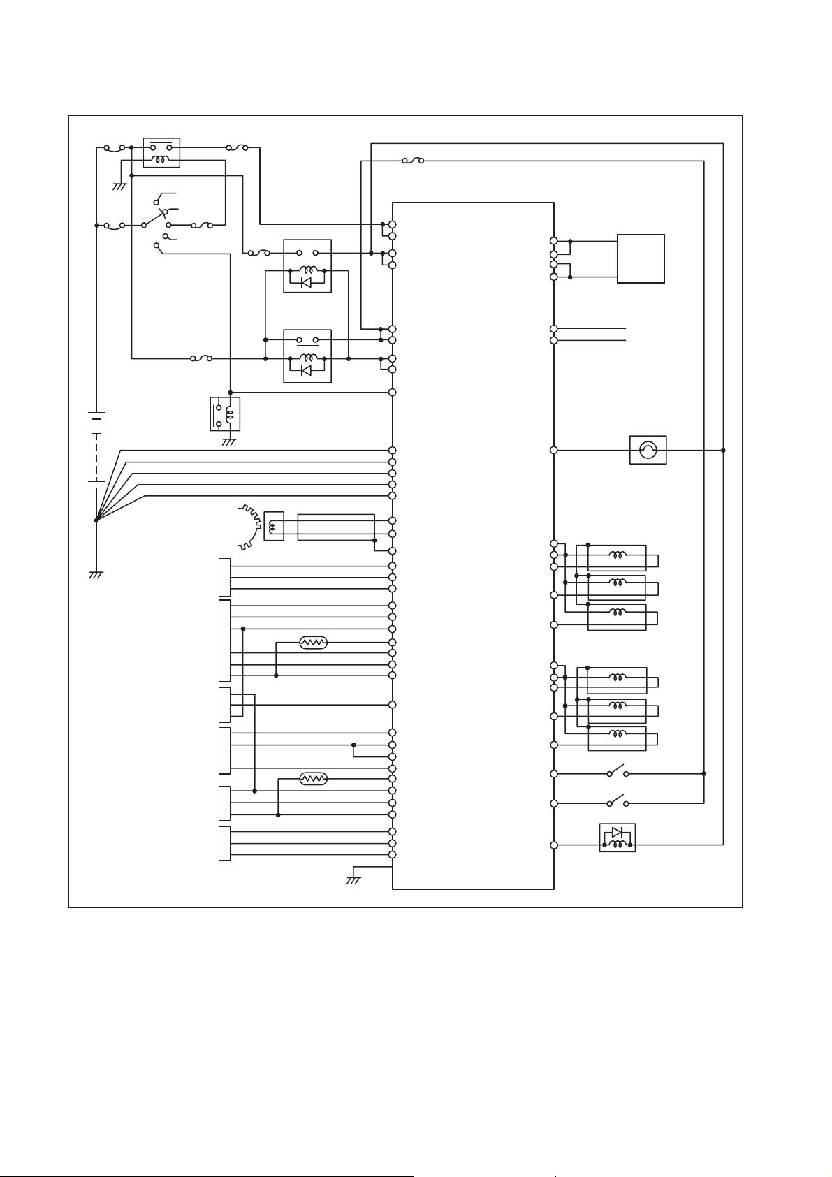
[2] ECU External Wiring Diagram
Power 4 relay
50 A
30 A
Battery
12 V
Engine speed sensor
Accelerator position sensor
Accelerator position sensor
Rail pressure sensor
Idle controller
Boost pressure sensor
5 A
15 A
TDC sensor
ACT power relay
15 A
Main relay
Starter relay
KEY/SW
KEY/SW
+BF
+BF
+BP
+BP
M-REL
M-REL
ST/SW
GND
GND
P-GND
P-GND
P-GND
NE [+]
NE [-]
NE-SLD
G-VCC
G
G-GND
A-VCC
ACCP1
Water temp. sensor
Fuel temp. sensor
A-GND
THW
ACCP2
A-GND
SCASC
A-VCC
VPC
VPC
A-GND
THL
A-VCC
VIMC
A-GND
A-VCC
PIM1
A-GND
Case GND
SCVHI
SCVHI
SCVLO
SCVLO
CANH
CANL
Lights
COMMON1
COMMON1
TWV1
TWV3
TWV5
COMMON2
COMMON2
TWV2
TWV4
TWV6
Switches
Actuators
SCV
For CAN wire
(Twist pair wire etc.)
Injector L6 (x6)
NOTE:
Dashed lines in the illustration show shield line.
Q000441E
44
Page 47

[3] ECU Connector Diagram
(1) ECU Connector Terminal Layout
34 P 35 P 32 P 35 P 31 P
2 3 4 5 6
1
8 9 10 11 12 13 14 15 16 17
18 19 20 21 22 23 24 25 26 27
28 29 30 31 32 33 34
7 35 36 37 38 39 40
42 43 44 45 46 47 48 49 50 51 52
54
55
56
62
57 58 59 60 61 87 88 89 90 91 92 93 94 95 96
63
64
65
66 67 68 69
41
70 71 72 73
53
77 78 79 80 81 82 83 84 85
97
98
74 75
99
76
86
100 101
102
108 109 110 111 112 113 11 4 115 116 117 144
118 119 120 121 122 123 124 125 126 127 128 154
129 130 131 132 133
103
104 105 106 107
134 135 136
137 138 139
140
145 146 147 148 149 150 151 152 153
155
156 157 158 159 160 161
162 163
164 165 166
(2) Terminal Connections
No.
Pin Symbol
1 (GND) ECU ground (spare) 18
2 (GND) ECU ground (spare) 19 KWP2000 ISO9141-K
3 IN3 spare 20 IN1 —
4 IN3- spare 21 AD1 Accelerator position sensor 1
5 +B Power 22 AD2 Accelerator position sensor 2
6 +B Power 23 AD10
7 +B Power 24 AD12 spare
8 TAC1 spare 25 AD19 spare
9 TAC2 Tachometer signal (SINK) 26 AD20 spare
10 POUT1 spare 27 VS1 Vehicle speed sensor
11 POUT2 spare 28
12 POUT3 spare 29 IN2 —
13 POUT4 spare 30 AD14 IMC volume
14 PIN1 spare 31 AD15 spare
15 PIN2 spare 32 AD16
16 — — 33 AD17 spare
17 (BATT) — 34 AD18 spare
35 +BF +BF 53 SW7 Brake switch
36 OUT5 Exhaust brake solenoid valve 54 A-GND4 Sensor ground 4
37 OUT6 spare 55 A-GND5 Sensor ground 5
38 OUT7 spare 56 SW1 Key switch
39 NE-SLD Engine RPM shield ground 57 A-VCC4 Sensor (Power supply) 4
40 NE+ Engine RPM + 58 SW8 Accelerator pedal switch
41 NE- Engine RPM - 59 SW10 spare
42 OUT1 spare 60 SW12 Constant-speed switch
43 OUT2 spare 61 SW17 Stop lamp switch
44 OUT3 Exhaust brake light 62 AD21 spare
45 OUT4 Glow indicator light 63 AD22 EGR valve lift sensor 2
46 SW1 Key switch 64 — —
47 OUT8 spare 65 A-VCC5 Sensor (Power supply) 5
48 SW2 Starter switch 66 SW9 Neutral switch
49 SW3 Exhaust brake switch 67 SW11 spare
50 SW4 spare 68 SW16 Diag. switch
51 SW5 spare 69 SW18 spare
52 SW6 spare
Connections No.
Pin Symbol
(CASE GND)
CASE GND
Connections
Case ground (spare)
Accelerator position sensor for operation
Case ground
Intake air temp. sensor (Build-in Airflow meter)
141
142
143
Q000442E
167
45
Page 48

No.
Pin Symbol
70 OUT19 Glow relay 86 — —
71 OUT20 Glow relay 87 SW31 AT identification signal
72 GND ECU ground 88 SW20 PTO2 switch
73 GND ECU ground 89 SW21 PTO switch
74 OUT17 ECU main relay 90 SW25 spare
75 OUT18 ECU main relay 91 SW26 spare
76 +BF +BF 92 SW13 Cruise switch 1
77 SW27 Clutch switch 93 SW28 Clutch stroke switch
78 SW spare 94 SW29 spare
79 SW Cruise switch 2 95 CANH CAN2 HI
80 SW Stop lamp switch 2 96 CANL CAN2 LOW
81 SW spare 97 SW32 Hydraulic pressure switch
82 S-OUT1 Check engine light 1 98 SW22 Warm-up switch
83 S-OUT2 spare 99 SW23 spare
84 S-OUT3 spare 100 SW30 spare
85 S-OUT4 spare 101 CAN-SLD CAN2 Shield ground
102 P-GND Power ground 120 G Cam angle
103 TWV1 Injector drive signal 1 121 AD4 Rail pressure sensor 1
104 TWV3 Injector drive signal 3 122 AD11 Airflow meter
105 TWV5 Injector drive signal 5 123 A-VCC3 Sensor (Power supply) 3
106
COMMON1
COMMON1
107
108 OUT9 EGR linear solenoid drive 1 126 A-VCC1 Sensor (Power supply) 1
109 OUT10 EGR linear solenoid drive 2 127 AD13 EGR valve lift sensor 1
110 OUT11 spare 128 AD3 Boost pressure sensor
111 OUT12 spare 129 (GND) ECU ground (spare)
112 OUT13 Cruise lamp 130 (GND) ECU ground (spare)
113 OUT14 Constant-speed lamp 131 G-GND CAM angle ground
114 OUT15 spare 132 AD5 Rail pressure sensor 2
115 OUT16 spare 133 G-VCC Cam angle VCC (5V)
116 — — 134 A-GND1 Sensor ground 1
117 — — 135 A-GND2 Sensor ground 2
118 A-GND6 Airflow ground 136 A-GND3 Sensor ground 3
119
NE (MRE)
Injector drive power 1 124 NE-VCC spare
Injector drive power 1 125 A-VCC2 Sensor (Power supply) 2
Connections No.
Pin Symbol
Connections
46
Page 49
No.
Pin Symbol
137 TWV2 Injector drive signal 2 153 PCV1 spare
138 TWV4 Injector drive signal 4 154 AD6 spare
139 TWV6 Injector drive signal 6 155 AD7 Water temp. sensor
140 P-GND Power ground 156 — —
141 P-GND Power ground 157 CAN1H CAN1 HI
142
COMMON2
COMMON2
143
144 SCVLO
145 SCVLO
146 SCVHI HP 3 or 4 pump control valve power 162 AD8 spare
147 SCVHI HP 3 or 4 pump control valve power 163 AD9 Fuel temp. sensor 2
148 — — 164 — —
149 — — 165
150 PCV2 spare 166 — —
151 PCV2 spare 167
152 PCV1 spare
Built-in
PATM Atmospheric air pressure sensor
Injector drive power 2 158 CAN1L CAN1 LOW
Injector drive power 2 159 — —
HP 3 or 4 pump control valve drive signal
HP 3 or 4 pump control valve drive signal
Connections No.
160 — —
161
Pin Symbol
(CASE GND)
CAN1-SLD
(CASE GND)
Connections
Case ground (spare)
spare
Case ground (spare)
47
Page 50

48
 Loading...